EP2198799A1 - Electrosurgical ablator with a scalloped electrode - Google Patents
Electrosurgical ablator with a scalloped electrode Download PDFInfo
- Publication number
- EP2198799A1 EP2198799A1 EP09179196A EP09179196A EP2198799A1 EP 2198799 A1 EP2198799 A1 EP 2198799A1 EP 09179196 A EP09179196 A EP 09179196A EP 09179196 A EP09179196 A EP 09179196A EP 2198799 A1 EP2198799 A1 EP 2198799A1
- Authority
- EP
- European Patent Office
- Prior art keywords
- electrode
- scalloped
- base
- ring
- grooves
- Prior art date
- Legal status (The legal status is an assumption and is not a legal conclusion. Google has not performed a legal analysis and makes no representation as to the accuracy of the status listed.)
- Granted
Links
- 229910052751 metal Inorganic materials 0.000 claims abstract description 12
- 239000002184 metal Substances 0.000 claims abstract description 12
- 241000237509 Patinopecten sp. Species 0.000 claims description 37
- 235000020637 scallop Nutrition 0.000 claims description 37
- 230000036961 partial effect Effects 0.000 claims description 2
- 238000003780 insertion Methods 0.000 claims 1
- 230000037431 insertion Effects 0.000 claims 1
- 230000003247 decreasing effect Effects 0.000 abstract description 8
- 241001631457 Cannula Species 0.000 abstract description 3
- 239000000523 sample Substances 0.000 description 37
- 239000012530 fluid Substances 0.000 description 24
- 210000001519 tissue Anatomy 0.000 description 23
- 238000000034 method Methods 0.000 description 20
- 238000002679 ablation Methods 0.000 description 12
- 150000001875 compounds Chemical class 0.000 description 9
- 239000012212 insulator Substances 0.000 description 9
- 230000000712 assembly Effects 0.000 description 8
- 238000000429 assembly Methods 0.000 description 8
- 238000001356 surgical procedure Methods 0.000 description 7
- FAPWRFPIFSIZLT-UHFFFAOYSA-M Sodium chloride Chemical compound [Na+].[Cl-] FAPWRFPIFSIZLT-UHFFFAOYSA-M 0.000 description 6
- 230000008569 process Effects 0.000 description 6
- PXHVJJICTQNCMI-UHFFFAOYSA-N Nickel Chemical compound [Ni] PXHVJJICTQNCMI-UHFFFAOYSA-N 0.000 description 4
- 239000000919 ceramic Substances 0.000 description 4
- 239000003989 dielectric material Substances 0.000 description 4
- 210000000629 knee joint Anatomy 0.000 description 4
- 229910001092 metal group alloy Inorganic materials 0.000 description 4
- 150000002739 metals Chemical class 0.000 description 4
- BASFCYQUMIYNBI-UHFFFAOYSA-N platinum Chemical compound [Pt] BASFCYQUMIYNBI-UHFFFAOYSA-N 0.000 description 4
- 239000002918 waste heat Substances 0.000 description 4
- 238000003466 welding Methods 0.000 description 4
- 230000007423 decrease Effects 0.000 description 3
- 210000003127 knee Anatomy 0.000 description 3
- 239000000463 material Substances 0.000 description 3
- 239000011780 sodium chloride Substances 0.000 description 3
- 229910001020 Au alloy Inorganic materials 0.000 description 2
- 239000004593 Epoxy Substances 0.000 description 2
- 229910001182 Mo alloy Inorganic materials 0.000 description 2
- ZOKXTWBITQBERF-UHFFFAOYSA-N Molybdenum Chemical compound [Mo] ZOKXTWBITQBERF-UHFFFAOYSA-N 0.000 description 2
- 229910000990 Ni alloy Inorganic materials 0.000 description 2
- 229910001260 Pt alloy Inorganic materials 0.000 description 2
- 229910001069 Ti alloy Inorganic materials 0.000 description 2
- RTAQQCXQSZGOHL-UHFFFAOYSA-N Titanium Chemical compound [Ti] RTAQQCXQSZGOHL-UHFFFAOYSA-N 0.000 description 2
- 208000027418 Wounds and injury Diseases 0.000 description 2
- PSLUFJFHTBIXMW-WYEYVKMPSA-N [(3r,4ar,5s,6s,6as,10s,10ar,10bs)-3-ethenyl-10,10b-dihydroxy-3,4a,7,7,10a-pentamethyl-1-oxo-6-(2-pyridin-2-ylethylcarbamoyloxy)-5,6,6a,8,9,10-hexahydro-2h-benzo[f]chromen-5-yl] acetate Chemical compound O([C@@H]1[C@@H]([C@]2(O[C@](C)(CC(=O)[C@]2(O)[C@@]2(C)[C@@H](O)CCC(C)(C)[C@@H]21)C=C)C)OC(=O)C)C(=O)NCCC1=CC=CC=N1 PSLUFJFHTBIXMW-WYEYVKMPSA-N 0.000 description 2
- 239000004020 conductor Substances 0.000 description 2
- 238000005520 cutting process Methods 0.000 description 2
- 238000005516 engineering process Methods 0.000 description 2
- -1 for example Inorganic materials 0.000 description 2
- 239000011521 glass Substances 0.000 description 2
- PCHJSUWPFVWCPO-UHFFFAOYSA-N gold Chemical compound [Au] PCHJSUWPFVWCPO-UHFFFAOYSA-N 0.000 description 2
- 239000010931 gold Substances 0.000 description 2
- 229910052737 gold Inorganic materials 0.000 description 2
- 239000003353 gold alloy Substances 0.000 description 2
- 238000010438 heat treatment Methods 0.000 description 2
- 239000011810 insulating material Substances 0.000 description 2
- 239000007788 liquid Substances 0.000 description 2
- 239000000203 mixture Substances 0.000 description 2
- 229910052750 molybdenum Inorganic materials 0.000 description 2
- 239000011733 molybdenum Substances 0.000 description 2
- 229910052759 nickel Inorganic materials 0.000 description 2
- 229910001000 nickel titanium Inorganic materials 0.000 description 2
- 230000037361 pathway Effects 0.000 description 2
- 239000004033 plastic Substances 0.000 description 2
- 229910052697 platinum Inorganic materials 0.000 description 2
- 238000007493 shaping process Methods 0.000 description 2
- 239000002210 silicon-based material Substances 0.000 description 2
- 229910001220 stainless steel Inorganic materials 0.000 description 2
- 239000010935 stainless steel Substances 0.000 description 2
- 229910001256 stainless steel alloy Inorganic materials 0.000 description 2
- 239000010936 titanium Substances 0.000 description 2
- 238000009834 vaporization Methods 0.000 description 2
- 230000008016 vaporization Effects 0.000 description 2
- 230000004913 activation Effects 0.000 description 1
- 210000003484 anatomy Anatomy 0.000 description 1
- 210000003423 ankle Anatomy 0.000 description 1
- QVGXLLKOCUKJST-UHFFFAOYSA-N atomic oxygen Chemical compound [O] QVGXLLKOCUKJST-UHFFFAOYSA-N 0.000 description 1
- 230000000740 bleeding effect Effects 0.000 description 1
- 238000009835 boiling Methods 0.000 description 1
- 230000001112 coagulating effect Effects 0.000 description 1
- 230000015271 coagulation Effects 0.000 description 1
- 238000005345 coagulation Methods 0.000 description 1
- 230000006378 damage Effects 0.000 description 1
- 230000000694 effects Effects 0.000 description 1
- 210000001513 elbow Anatomy 0.000 description 1
- 210000002683 foot Anatomy 0.000 description 1
- 210000001624 hip Anatomy 0.000 description 1
- 230000006872 improvement Effects 0.000 description 1
- 239000011261 inert gas Substances 0.000 description 1
- 230000002401 inhibitory effect Effects 0.000 description 1
- 238000002347 injection Methods 0.000 description 1
- 239000007924 injection Substances 0.000 description 1
- 208000014674 injury Diseases 0.000 description 1
- 230000001788 irregular Effects 0.000 description 1
- 230000000670 limiting effect Effects 0.000 description 1
- 238000004519 manufacturing process Methods 0.000 description 1
- 230000005499 meniscus Effects 0.000 description 1
- 238000012986 modification Methods 0.000 description 1
- 230000004048 modification Effects 0.000 description 1
- 239000001301 oxygen Substances 0.000 description 1
- 229910052760 oxygen Inorganic materials 0.000 description 1
- 238000004806 packaging method and process Methods 0.000 description 1
- 238000012536 packaging technology Methods 0.000 description 1
- 239000004810 polytetrafluoroethylene Substances 0.000 description 1
- 229920001343 polytetrafluoroethylene Polymers 0.000 description 1
- 230000036316 preload Effects 0.000 description 1
- 238000011084 recovery Methods 0.000 description 1
- 210000002832 shoulder Anatomy 0.000 description 1
- 238000006467 substitution reaction Methods 0.000 description 1
- 238000012800 visualization Methods 0.000 description 1
Images


Classifications
-
- A—HUMAN NECESSITIES
- A61—MEDICAL OR VETERINARY SCIENCE; HYGIENE
- A61B—DIAGNOSIS; SURGERY; IDENTIFICATION
- A61B18/00—Surgical instruments, devices or methods for transferring non-mechanical forms of energy to or from the body
- A61B18/04—Surgical instruments, devices or methods for transferring non-mechanical forms of energy to or from the body by heating
- A61B18/12—Surgical instruments, devices or methods for transferring non-mechanical forms of energy to or from the body by heating by passing a current through the tissue to be heated, e.g. high-frequency current
- A61B18/14—Probes or electrodes therefor
- A61B18/148—Probes or electrodes therefor having a short, rigid shaft for accessing the inner body transcutaneously, e.g. for neurosurgery or arthroscopy
-
- A—HUMAN NECESSITIES
- A61—MEDICAL OR VETERINARY SCIENCE; HYGIENE
- A61B—DIAGNOSIS; SURGERY; IDENTIFICATION
- A61B18/00—Surgical instruments, devices or methods for transferring non-mechanical forms of energy to or from the body
- A61B2018/00053—Mechanical features of the instrument of device
- A61B2018/00059—Material properties
- A61B2018/00071—Electrical conductivity
- A61B2018/00083—Electrical conductivity low, i.e. electrically insulating
-
- A—HUMAN NECESSITIES
- A61—MEDICAL OR VETERINARY SCIENCE; HYGIENE
- A61B—DIAGNOSIS; SURGERY; IDENTIFICATION
- A61B18/00—Surgical instruments, devices or methods for transferring non-mechanical forms of energy to or from the body
- A61B18/04—Surgical instruments, devices or methods for transferring non-mechanical forms of energy to or from the body by heating
- A61B18/12—Surgical instruments, devices or methods for transferring non-mechanical forms of energy to or from the body by heating by passing a current through the tissue to be heated, e.g. high-frequency current
- A61B18/14—Probes or electrodes therefor
- A61B2018/1472—Probes or electrodes therefor for use with liquid electrolyte, e.g. virtual electrodes
Landscapes
- Health & Medical Sciences (AREA)
- Surgery (AREA)
- Engineering & Computer Science (AREA)
- Life Sciences & Earth Sciences (AREA)
- Physics & Mathematics (AREA)
- Heart & Thoracic Surgery (AREA)
- Nuclear Medicine, Radiotherapy & Molecular Imaging (AREA)
- Otolaryngology (AREA)
- Neurology (AREA)
- Biomedical Technology (AREA)
- Neurosurgery (AREA)
- Plasma & Fusion (AREA)
- Medical Informatics (AREA)
- Molecular Biology (AREA)
- Animal Behavior & Ethology (AREA)
- General Health & Medical Sciences (AREA)
- Public Health (AREA)
- Veterinary Medicine (AREA)
- Surgical Instruments (AREA)
Abstract
Description
- The present application relates to the field of electrosurgery and, in particular, to electrosurgical devices and methods which employ high frequency voltage to cut, ablate or coagulate tissue in a fluid environment.
- Radiofrequency (RF) probes employed in electrosurgical procedures are generally divided into two categories: monopolar devices and bipolar devices. In monopolar electrosurgical devices, the RF current generally flows from an exposed active electrode through the patient's body, to a passive or return current electrode that is externally attached to a suitable location on the patient's skin. In bipolar electrosurgical device, both the active and the return current electrodes are exposed and are typically in close proximity. The RF current flows from the active electrode to the return electrode through the tissue. Thus, in contrast with the monopolar electrosurgical devices, the return current path for a bipolar device does not pass through the patient's body except for close proximity to the tip of the electrode.
- Electrosurgery is the intentional passage of high frequency current through tissue to achieve a controlled surgical effect. This can be accomplished in an oxygen rich, an inert gas, or a conductive fluid media environment. Arthroscopic tissue ablation is performed in a conductive fluid environment, such as inside of a joint or body cavity filled with, for instance, normalized saline solution, and differs from that described previously in that current is conducted from the active electrode through the fluid to the return electrode. In the case of a monopolar device, the current flows through the patient to the return electrode in the manner previously described. In the case of bipolar devices operating in a conductive fluid environment, the return electrode is not in contact with tissue, but rather is submerged in the conductive fluid in the proximity of the active electrode. Current flow is from the active electrode through the conductive liquid and surrounding tissues to the return electrode of the bipolar device. Whether an electrode is monopolar or bipolar, current flows from all uninsulated surfaces of the active electrode to the return electrode anytime that the probe is energized. This is in contrast to conventional surgery (also called "open surgery") in which current flows only through electrode surfaces in contact with the patient's tissue.
- During the past several years, specialized arthroscopic electrosurgical probes also called ablators have been developed for arthroscopic surgery. Ablators differ from the conventional arthroscopic electrosurgical probes in that they are designed for the bulk removal of tissue by vaporization, rather than by cutting the tissue or coagulating the bleeding vessels. This way, during ablation, volumes of tissue are vaporized rather then discretely cut out and removed from the surgical site. Aspiration ports in the ablator are often provided to remove ablated tissue and debris.
- The power requirements of ablators are generally higher than those of other arthroscopic probes. The efficiency of the probe design and the characteristics of the radio frequency (RF) power supplied to the probe also affect the amount of power required for ablation. For example, probes with inefficient designs and/or powered by RF energy with poorly suited characteristics will require higher powers levels than those with efficient designs and appropriate generators. Probes used in electrosurgery have relatively large area of metallic electrode, which is the active area of the probe. Large electrode area decreases the probe impedance and, therefore, increases the RF power required for proper operation. The shape of the dielectric insulator and of the probe tip can significantly affect ablation. By properly shaping the insulator and the electrode tip, the threshold power can be substantially decreased.
- A recent improvement to ablation electrodes is the addition of aspiration to remove bubbles and debris from the surgical site. During electrosurgery in a conductive fluid environment, tissue is vaporized, thereby producing steam bubbles which may obscure the view of the surgeon or displace saline from the area of the intra-articular space which the surgeon wishes to affect. In the case of ablation (bulk vaporization of tissue), the number and volume of bubbles produced is even greater than when using other electrodes since fluid is continually boiling at the active electrode during use. Ideally, flow through the joint carries these bubbles away; however, in certain procedures this flow is frequently insufficient to remove all of the bubbles. Aspiration removes some bubbles as they are formed by the ablation process, and others after they have collected in pockets within the joint. The aspiration portal is connected to an external vacuum source which provides suction for bubble evacuation.
- Aspirating ablators are divided into two categories according to their level of flow. High-flow ablators have an aspiration tube, the axis of which is coaxial with the axis of the ablator rod or tube, which draws in bubbles and fluid through its distal opening and/or openings cut into the tube wall near its distal tip. High-flow ablators may decrease the average joint fluid temperature by removing heated saline (waste heat since it is an undesirable biproduct of the process) from the general area in which ablation is occurring. The effectiveness of the aspiration, both for removal of bubbles and for removal of waste heat, will be affected by the distance between the opening through which aspiration is accomplished and the active electrode. The distal tip of the aspiration tube is generally several millimeters distant proximally from the active electrode so as to not to obstruct the surgeon's view of the electrode during use. Decreasing this distance is desirable since doing so will increase the effectiveness of the aspiration. However, this must be accomplished without limiting the surgeon's view or decreasing the ablator's ability to access certain structures during use.
- Low-flow ablators are those which aspirate bubbles and fluid through gaps in the ablating surfaces of the active electrode and convey them from the surgical site via means in the elongated distal portion of the device. Current low-flow ablators require increased power to operate as effectively as a nonaspirating or high-flow aspirating ablators because the low-flow aspiration draws hot saline from the active site of a thermal process. In the case of low-flow ablators, the heat removed is necessary process heat rather than the waste heat removed by high-flow ablators. Because of this, aspirating ablators of the low-flow type generally require higher power levels to operate than other ablators thereby generating more waste heat and increasing undesirable heating of the fluid within the joint.
- Each of these types of aspirating ablation electrodes has its drawbacks. In the case of high-flow aspirating ablators, the aspiration tube increases the diameter of the device thereby necessitating the use of larger cannulae which, in turn, results in an increase in wound size and often an increase in patient pain and recovery time. In the case of low-flow aspirating ablators, the devices decrease the efficiency of the probes since process heat is removed from a thermal process. This decreased efficiency results in decreased rates of tissue removal for a given power level. This results in increased procedure times or necessitates the use of higher power levels to achieve satisfactory tissue removal rates. High power levels are undesirable as they cause increased heating of the fluid at the site and thereby increase the likelihood of thermal injury to the patient.
- Accordingly, it is desirable to provide an electrosurgical probe of high efficiency and high impedance with an improved design of the aspiration port, and which is capable of conferring high ablation rates at low RF power levels. An electrosurgical ablation electrode with an advanced electrode and tube design is also desirable.
- The present invention provides a surgical ablating instrument having an advanced electrode and tube design, with a swaged and bent one-piece metal tube that fits in small cannulas (as small as a 5.5mm cannula). The electrode has a scalloped configuration that provides decreased surface area with more edges. The handle is provided with an ergonomic design that utilizes a bend with a cut at the end of the tube (for example, a 30 degree bend with a 15 degree cut). The surgical instrument may be provided with a novel insulative design.
- Other features and advantages of the present invention will become apparent from the following description of the invention which refers to the accompanying drawings.
-
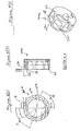
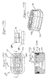
Figure 1(a) illustrates a perspective view of a scalloped electrode (with a 7-face scallop electrode base and a 10-face scallop electrode ring) according to an embodiment of the present invention. -
Figure 1(b) illustrates a perspective view of an scalloped electrode (with a 7-face scallop electrode base and a 20-face scallop electrode ring) according to an embodiment of the present invention. -
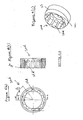
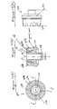
Figures 2(a)-(d) illustrate a top view, perspective view, side view and cross-sectional view, respectively, of a 7-face electrode base (special machined configuration, and also illustrated inFigures 1(a) and 1(b) ) of a scalloped electrode according to another embodiment of the present invention. -
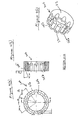
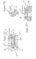
Figures 3(a)-(c) illustrate a top view, cross-sectional view and perspective view, respectively, of a 10-face scallop electrode ring (special machined configuration, and also illustrated inFigure 1(a) ) of a scalloped electrode according to another embodiment of the present invention. -
Figures 4(a)-(c) illustrate a top view, cross-sectional view and perspective view, respectively, of a 20-face scallop electrode ring (special machined configuration, and also illustrated inFigure 1(a) ) of a scalloped electrode according to another embodiment of the present invention. -
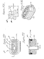
Figures 5(a)-(c) illustrate a top view, cross-sectional view and perspective view, respectively, of a 5-face scallop electrode ring (special machined configuration) of a scalloped electrode according to another embodiment of the present invention. -
Figure 6(a)-(c) illustrate a top view, cross-sectional view and perspective view, respectively, of a 10-face scallop electrode ring (special machined configuration) of a scalloped electrode according to another embodiment of the present invention. -
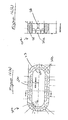
Figures 7(a)-(c) illustrate a top view, side view and cross-sectional view, respectively, of a scalloped electrode (with a 7-face scallop electrode base and 20-face scallop electrode ring (metal assembly)) according to another embodiment of the present invention. -
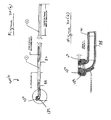
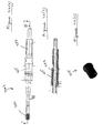
Figure 8(a) illustrates a perspective view of an electrode assembly of the present invention, with a 30 degree swaged tube and with the scalloped electrode ofFigures 1-7 . -
Figure 8(b) illustrates an enlarged view of the distal end of the electrode assembly ofFigure 8(a) . -
Figure 8(c) illustrates a side view of the electrode assembly ofFigure 8(a) . -
Figure 8(d) illustrates an enlarged view of the distal end of the electrode assembly ofFigure 8(b) . -
Figure 8(e) illustrates a view of the swaged area of the distal end of the electrode assembly ofFigure 8(d) , taken along line A ofFigure 8(d) . -
Figure 9(a) illustrates a perspective view of another electrode assembly of the present invention, with acompound 45 degree assembly (with a 30 degree swaged tube and with an insulated probe assembly (with a scalloped electrode)). -
Figure 9(b) illustrates a side view of the electrode assembly ofFigure 9(a) . -
Figure 9(c) illustrates an enlarged view of the distal end of the electrode assembly ofFigure 9(b) . -
Figure 10(a) illustrates a perspective view of another electrode assembly of the present invention, with acompound 90 degree assembly (with a 30 degree swaged tube and with an insulated probe assembly (with a scalloped electrode)). -
Figure 10(b) illustrates a side view of the electrode assembly ofFigure 10(a) . -
Figure 10(c) illustrates an enlarged view of the distal end of the electrode assembly ofFigure 10(b) . -
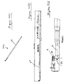
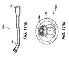
Figure 11(a) illustrates a side view of a distal end of a scalloped electrode assembly with a 45 degree swaged tube version, with a 30 degree bent and a 15 degree cut at the end of the tube, according to another embodiment of the present invention. -
Figure 11(b) illustrates a top view of a distal end of the scalloped electrode assembly ofFigure 11(a) . -
Figure 12(a) illustrates a perspective view of a 7-face electrode plugged base (non-aspirating base) of a scalloped electrode according to another embodiment of the present invention. -
Figure 12(b) illustrates another perspective view of the 7-face electrode plugged base ofFigure 12(a) . -
Figures 12(c)-(e) illustrate a top view, a side view, and a cross-sectional view, respectively, of the 7-face electrode plugged base ofFigure 12(a) . -
Figures 13(a)-(c) illustrate a top view, a cross-sectional view, and a side view, respectively, of a scalloped electrode (with a 7-face scallop electrode plugged base and with a 20-face scallop electrode ring (metal assembly)) according to another embodiment of the present invention. -
Figures 14(a)-(c) illustrate a top view, a cross-sectional view, and a detailed view, respectively, of an exemplary electrode plugged base (special machined configuration, with a novel scallop and slot design, and a substantially rectangular configuration) of a scalloped electrode according to another embodiment of the present invention. -
Figures 15(a)-(c) illustrate a top view, a cross-sectional view, and a detailed view, respectively, of an exemplary electrode aspirating base (special machined configuration, with a novel scallop and slot design, and a substantially rectangular configuration) of a scalloped electrode according to another embodiment of the present invention. -
Figures 16(a) and (b) illustrate a top view and a cross-sectional view, respectively, of an exemplary 32-face scallop electrode ring (special machined configuration, and with a substantially rectangular configuration) of a scalloped electrode according to another embodiment of the present invention. -
Figures 17(a)-(d) illustrate a top view, side view, cross-sectional view, and perspective view, respectively, of an aspirating scalloped electrode (with the exemplary electrode aspirating base ofFigures 15(a)-(c) and the exemplary 32-face scallop electrode ring ofFigures 16(a) and (b) ) according to another embodiment of the present invention. -
Figures 18(a)-(d) illustrate a top view, side view, cross-sectional view, and perspective view, respectively, of a non-aspirating scalloped electrode (with the exemplary electrode plugged base ofFigures 14(a)-(c) and the exemplary 32-face scallop electrode ring ofFigures 16(a) and (b) ) according to another embodiment of the present invention. -
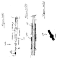
Figure 19(a) illustrates a side view of another electrode assembly of the present invention, with acompound 90 degree assembly (with a 30 degree swaged tube and with the scalloped electrode ofFigures 17(a)-(d) ). -
Figure 19(b) illustrates an enlarged view of the distal end of the electrode assembly ofFigure 19(a) . -
Figure 20(a) illustrates a side view of another electrode assembly of the present invention, with acompound 90 degree assembly (with a 30 degree swaged tube and with an insulated probe assembly (with the scalloped electrode ofFigures 17(a)-(d) ). -
Figure 20(b) illustrates an enlarged view of the distal end of the electrode assembly ofFigure 20(a) . -
Figures 20(c)-(e) illustrate a top view, lateral view, and side view, respectively, of the assembly ofFigure 20(b) . -
Figure 21(a) illustrates a top view of another electrode assembly of the present invention, with a 30 degree swaged tube, a scalloped electrode, and a first insulative overmold. -
Figure 21(b) illustrates a cross-sectional view of the assembly ofFigure 21(a) . -
Figure 21(c) illustrates a perspective view of the first insulative overmold of the assembly ofFigure 21(a) . -
Figure 22(a) illustrates a top view of the electrode assembly ofFigure 21(a) (having a 30 degree swaged tube, a scalloped electrode, and a first insulative overmold) and with an additional second insulative overmold. -
Figure 22(b) illustrates a cross-sectional view of the assembly ofFigure 22(a) . -
Figure 22(c) illustrates a perspective view of the second insulative overmold of the assembly ofFigure 22(a) . -
Figures 23(a)-(e) illustrate a perspective view, top view, side view, and two end views, respectively, of an ablating device with a scalloped electrode assembly of the present invention. -
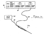
Figure 24 is a schematic representation of an electrosurgical system according to the principles of the present invention. -
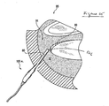
Figure 25 is a schematic cross-sectional view of a knee joint undergoing an electrosurgical procedure employing a scalloped electrode assembly of the present invention. - The present invention provides a surgical ablating instrument having an advanced electrode design, with a swaged one-piece metal tube that fits in a small cannula (as small as a 5.5mm cannula, for example). The electrode has a scalloped configuration that provides decreased surface area with more edges (facets). The electrode may have an aspirating (i.e., suction through the electrode face) or a non-aspirating (or plugged or obstructed base) profile. The instrument may be provided with an advanced insulative overmold design.
- The scallop electrode device of the present invention has a multi-facet design, delivers a maximum height offset between the electrode face and the coated shaft (for example, a 0.094 height offset with heat shrink), fits a small cannula (as small as a 5.5mem diameter cannula, for example), provides suction through the electrode face, provides self-clearing suction pathway capabilities, does not require the use of a ceramic insulator, is heat-shrink compatible, is portable to various surgical application, reduces the suggested ESU power setting requirements, utilizes a more ergonomically-designed next generation handle, may incorporate a suction flow regulator scheme if required by a specific application (such as, for example, a suction flow regulator as described in
U.S. Provisional Appl. No. 61/138,034, filed on December 16, 2008 - Referring now to the drawings, where like elements are designated by like reference numerals,
Figures 1-25 illustrate various structural elements of scalloped electrodes and assemblies of the present invention. -
Figures 1-7 illustrate scalloped electrodes (with a scalloped base and a scalloped ring) according to embodiments of the present invention. The electrodes ofFigures 1-7 are exemplary aspirating electrodes (i.e., aspiration and suction is conducted through the electrode).Figure 8-11 illustrate various embodiments of swaged tubes that are employed with the electrodes ofFigures 1-7 . The probe assemblies ofFigures 8-11 are exemplary 45 or 90 degree compound assemblies (with a 30 degree bend and a 15 degree cut at the end of the tube) that may be insulated or non-insulated. -
Figure 12 illustrates views of a scalloped electrode base that has a non-aspirating or plugged design (i.e., aspiration and suction is not permitted through the electrode face).Figure 13 illustrates an exemplary scalloped electrode (with the scalloped plugged base ofFigure 12 and a scalloped ring). -
Figures 14-20 illustrates views of a scalloped electrodes and probe assemblies (with aspirating or non-aspirating designs) provided with electrode bases and rings having a combined scallop and slot design, and with a substantially rectangular cross-sectional views. These exemplary probe assemblies may be 45 or 90 degree compound assemblies (with a 30 degree bend and a 15 degree cut at the end of the tube) that may be insulated or non-insulated.Figures 21 and22 illustrate details of a novel insulative design assembly of the present invention (with first and second overmolds). - The scalloped electrodes illustrated in the drawings have a scallop or scalloped design when viewed from a top view of the electrode, i.e., when viewed in a direction about perpendicular to a most distal surface of the electrode. As detailed below, these electrodes (base and/or ring) may have various cross-sectional shapes and geometries, for example, round or circular, eliptical, oval, square, or rectangular, or any combination of these geometries.
- The scalloped electrodes include different numbers of edges or facets (grooves) machined within the electrode base and/or the electrode ring. These scalloped grooves may have a regular or irregular configuration, depending on the specific application. The scalloped grooves may be provided on either the inner surface or the outer surface, or both the inner and outer surfaces, of the electrode base or the electrode ring (or both the electrode base and the electrode ring). In certain embodiments, the electrode base may not be provided with a scalloped pattern, but only the ring electrode (with scalloped grooves provided on either the inner surface or the outer surface, or both the inner and outer surfaces, of the electrode ring). In other embodiments, the electrode ring may not be provided with a scalloped pattern, but only the base electrode (with scalloped grooves provided on either the inner surface or the outer surface, or both the inner and outer surfaces, of the electrode base). In yet other embodiments, the scalloped grooves are provided on both the base electrode and the ring electrode (with scalloped grooves provided on either the inner surface or the outer surface, or both the inner and outer surfaces, of each of the electrode base and electrode ring). The scalloped grooves may have a semi-circular or semi-elliptical shape and may be evenly spaced around an inner and/or outer surface of the base electrode or the ring electrode. The radii of the scalloped grooves may be similar or different. The radii of the scalloped grooves of the electrode base may be similar to or different from the radii of the scalloped grooves of the electrode ring.
- For example,
Figure 1(a) illustrates a perspective view of an exemplary embodiment of ascalloped electrode 50a of the present invention, with a 7-face scallop electrode base and a 10-facescallop electrode ring 20a.Figure 1(b) illustrates a perspective view of anotherscalloped electrode 50b, with a 7-facescallop electrode base 10 and a 20-facescallop electrode ring 20b. -
Electrode base 10 of the scalloped electrodes of the present invention is illustrated in more detail inFigures 2(a)-(d) .Grooves 15 are provided on theouter surface 13 of thetubular element 14 of thebase 10, as shown inFigures 2(b) and 2(d) , for example. A central lumen 11 of thebase 10 is defined by the inner surface of the tubular member 14 (i.e., the surface opposite theouter surface 13 defining the grooves). Central lumen 11 provides direct aspiration flow and suction. When viewed from a top view of the electrode base, i.e., when viewed from a direction about perpendicular to a most distal surface of thetubular member 14, mostdistal surface 18 has a scallop or scalloped configuration. - In an exemplary embodiment,
grooves 15 are machined within the electrode base.Grooves 15 may have a semi-circular or semi-elliptical shape (or a combination of these shapes) and may be evenly spaced around theouter surface 13 of the base electrode. The radii of thescalloped grooves 15 may be similar or different. The radii of thescalloped grooves 15 of theelectrode base 10 may be similar to or different from the radii of the scalloped grooves of the electrode ring (detailed below).Scalloped grooves 15 may be provided in any number onsurface 13 of the electrode base 10 (although the exemplary embodiment in the drawings shows seven machined grooves that are equally spaced apart around the circumference of the base, the invention is not limited to this specific embodiment, and contemplates any number of scalloped grooves on the inner and/or outer surfaces of the electrode base). - The electrode base 10 (with machined scalloped grooves 15) is preferably formed of electrically conductive materials such as metals and metal alloys, for example, stainless steel and stainless steel alloys, platinum and platinum alloys, gold and gold alloys, nickel and nickel alloys, titanium and titanium alloys, and molybdenum and molybdenum alloys, or combinations of such metals and metal alloys, among others.
-
Figures 3-6 illustrate various views and structural configurations ofelectrode rings Grooves 25a, 25b, 25c, 25d are machined within the outer or the inner surface of thering Figures 3(a)-(c) illustrate a 10-facescallop electrode ring 20a (special machined configuration, and also shown inFigure 1(a) ) with grooves 25a provided on bothinner surface 22 andouter surface 23 of thering electrode 20a. In the exemplary embodiment shown inFigures 3(a)-(c) , five grooves 25a are machined within inner surface 22 (Figure 3(c) ) ofring 20a, and five grooves 25a are machined within outer surface 23 (Figure 3(c) ) ofring 20a. Grooves 25a may have a semi-circular or semi-elliptical shape (or other configurations) and are evenly spaced aroundinner surface 22 andouter surface 23 of the ring electrode. When viewed from a top view of the electrode ring, i.e., when viewed from a direction about perpendicular to a most distal surface of thering 20a, mostdistal surface 28 has a scallop or scalloped configuration. The radii of the scalloped grooves 25a may be similar or different. The radii of the scalloped grooves 25a of theinner surface 22 may be similar to or different from the radii of the scalloped grooves 25a on theouter surface 23. -
Figures 4(a)-(c) illustrate a 20-facescallop electrode ring 20b (special machined configuration, and also shown inFigure 1(b) ) of a scalloped electrode according to another embodiment of the present invention. Grooves 25b are provided on bothinner surface 22 andouter surface 23 of thering electrode 20b. In the exemplary embodiment ofFigures 4(a)-(c) , ten equally spaced, semi-circular or semi-elliptical structures or grooves 25b are provided within inner surface 22 (Figure 4(c) ) ofring 20b, and ten equally spaced, semi-circular or semi-elliptical structures or grooves 25b within outer surface 23 (Figure 4(c) ) ofring 20b. Grooves 25b are evenly spaced aroundinner surface 22 andouter surface 23 of thering electrode 20b. The radii of the scalloped grooves 25b may be similar or different. The radii of the scalloped grooves 25b of theinner surface 22 may be similar to or different from the radii of the scalloped grooves 25b on theouter surface 23. -
Figures 5(a)-(c) illustrate a 5-face scallop electrode ring 20c (special machined configuration) according to another embodiment of the present invention.Grooves 25c are provided only oninner surface 22 of the ring electrode 20c. These grooves are also semi-circular or semi-elliptical structures, and are evenly spaced aroundinner surface 22 of the ring electrode 20c. The radii of the scallopedgrooves 25c may be similar or different. -
Figure 6(a)-(c) illustrate ascallop electrode ring 20d which is similar to that ofFigures 5(a)-(c) but differs in thatelectrode ring 20d is provided with 10 grooves, i.e., it is a 10-facescallop electrode ring 20d (special machined configuration). Grooves 25d are provided only on theinner surface 22 of thering electrode 20d. Grooves 25d are also semi-circular or semi-elliptical structures, and are evenly spaced aroundinner surface 22 of thering electrode 20d. The radii of the scalloped grooves 25d may be similar or different. -
Ring scalloped grooves 25a, 25b, 25c, 25d) may be formed of a material similar to or different from that of the electrode base 10 (with machined grooves 15). Thus,ring -
Figures 7(a)-(c) illustrate details ofexemplary electrode 50b of the present invention (also shown inFigure 1(b) ), which is formed by assemblingelectrode base 10 ofFigures 2(a)-(d) with theexemplary electrode ring 20b ofFigures 4(a)-(c) (i.e., the 20-facescallop electrode ring 20b).Ring 20b is securely attached tobase 10 by welding, for example, or by other known methods in the art. In the assembled state,tubular element 14 is concentric with thering electrode 20b, and the mostdistal surface 18 of thetubular element 14 of thebase 10 is about coplanar (coincides) with the mostdistal surface 28 ofelectrode ring 20b (as shown inFigure 7(c) , for example). Grooves 25b of theelectrode ring 20b andgrooves 15 of the base 10 form an alternating symmetrical pattern, as shown inFigure 7(a) . The grooves are evenly spaced relative to each of thetubular element 14 and thering electrode 20b, and are also symmetrically located relative to a longitudinal axis 19 (Figures 7(a) and (b) ) of thebase 10 andring 20b. - The electrodes of
Figures 1-7 detailed above employ anelectrode base 10 which has an aspirating profile (i.e., aspiration and suction is conducted through the central lumen 11 of thetubular member 14 of the base 10).Figure 8-11 illustrate various embodiments of swaged tubes that are employed with the electrodes ofFigures 1-7 . The probe assemblies ofFigures 8-11 are exemplary 45 or 90 degree compound assemblies (with a 30 degree bend and a 15 degree cut at the end of the tube) that may be insulated or non-insulated. For example,Figure 8(a) illustrates a perspective view of anelectrode assembly 100a of the present invention, with a one-piece 30 degree swaged andbent tube 80 and with a scalloped electrode (such as the exemplaryscalloped electrode 50b ofFigure 1(b) orFigures 7(a)-(c) ). As shown more clearly inFigure 8(d) ,distal tube portion 88 of thetube 80 is swaged in that it forms an angle α of about 30 degrees with the tube 80 (i.e.,longitudinal axis 81 of thetube 80 forms angle α withlongitudinal axis 83 of the swaged portion 88).Longitudinal axis 19 of theelectrode 50b forms an angle β (Figure 8(d) ) of about 45 degrees with thelongitudinal axis 81 of thetube 80. -
Figures 9(a)-(c) illustrate another electrode assembly 100b of the present invention, which is similar to theprobe assembly 100a (in that probe assembly 100b is also acompound 45 degree assembly (with a 30 degree swaged tube)) but differs in that it is insulated.Insulator 89 is provided around the outer surface of theelectrode face 23 of theelectrode ring 20b, to surround the non-grooved area of theouter surface 23 of the electrode ring and to abut the machined grooves 25b. -
Insulator 89 may comprise an insulating or dielectric material such as epoxy, plastic, silicon-based material, ceramic, glass or compositions of these mentioned materials, among many others. The dielectric material surrounds and insulates the metallic tip of the ablator electrode. -
Figures 10(a)-(c) illustrates another electrode assembly 100c of the present invention, which is similar to the probe assembly 100b (in that probe assembly 100c has a 30 degree swaged tube and is insulated), but differs in that is acompound 90 degree assembly (and not a 45 degree assembly as in probe 100b).Longitudinal axis 19 of theelectrode 50b forms an angle β1 (Figure 10(c) ) of about 90 degrees with thelongitudinal axis 81 of thetube 80. -
Figures 11(a) and 11(b) illustrate additional views of the scallopedelectrode assembly 100a ofFigures 8(a)-(e) with a 45 degree swaged tube version, with a 30 degree bent and a 15 degree cut at the end of the tube. -
Figures 12(a)-(e) illustrate a scallopedelectrode base 110 that has a non-aspirating or plugged design (i.e., aspiration and suction is not permitted through the electrode face), whileFigures 13(a)-(c) illustrate an exemplary scalloped electrode (with the scalloped plugged base ofFigure 12(a) and a scalloped ring).Scalloped electrode base 110 is similar to thebase 10 ofFigures 2(a)-(d) , in thatgrooves 15 are also provided on theouter surface 13 oftubular element 114 of the base 110 (in a manner and configuration similar to that of thegrooves 15 of the base 10). However, lumen 111 of the base 110 (defined by the inner surface of the tubular member 114) is plugged byportion 113 so that no direct aspiration flow and suction is provided. -
Figures 13(a)-(c) illustrateexemplary electrode 150 of the present invention, which is formed by assemblingelectrode non-aspirating base 110 ofFigures 12(a)-(e) with theexemplary electrode ring 20b ofFigures 4(a)-(c) (i.e., the exemplary 20-facescallop electrode ring 20b).Ring 20b is securely attached tobase 110 by welding, for example, or by other known methods in the art. In the assembled state,tubular element 114 is concentric with thering electrode 20b, and the mostdistal surface 118 of thetubular element 114 of thebase 110 is about coplanar (coincides) with the mostdistal surface 28 ofelectrode ring 20b (as shown inFigure 13(b) , for example). Grooves 25b of theelectrode ring 20b andgrooves 15 of the base 110 form an alternating symmetrical pattern, as shown inFigure 13(a) . The grooves are evenly spaced relative to each of thetubular element 114 and thering electrode 20b, and are also symmetrically located relative to a longitudinal axis 19 (Figures 13(a) and (b) ) of thebase 110 andring 20b. - Reference is now made to
Figures 14(a)-(c) which illustrate another exemplary embodiment of a scallopedelectrode base 210 which is similar to the scallopedelectrode base 110 ofFigures 12(a)-(e) in that it has a non-aspirating or plugged design (i.e., aspiration and suction is not permitted through the electrode face), but differs frombase 110 in that its cross-sectional view is a substantially rectangular view (and not circular, as for base 110), i.e., mostdistal surface 218 ofnon-aspirating base 210 has a scalloped rectangular configuration. The size of the scallopedelectrode base 210 is also substantially bigger than that ofelectrode base 110 ofFigures 12(a)-(e) . In an exemplary embodiment, the length L (Figure 14(b) ) of theelectrode base 210 is about 0.15 to about 0.2 inches, more preferably of about 0.172 inches, and the width W (Figure 14(a) ) of theelectrode base 210 is about 0.1 to about 0.12 inches, more preferably of about 0.109 inches. Because of its increased size, the design ofelectrode base 210 also incorporates a plurality of slots or channels around the circumference of the base and also extending on the mostdistal surface 218 of the base. For example,Figure 14(a) illustrates awide slot 222 disposed all around the circumference of the electrode base, as well as slots 222a and 222b disposed in the exemplary-only pattern shown inFigure 14(a) (i.e., with slots 222a forming a series of X patterns, and with slot 222b extending transversely between the two long edges or sides of the rectangular distal surface 218).Scalloped grooves 15 are also provided on theouter surface 213 ofelement 214 of the base 210 (in a manner and configuration similar to that of thegrooves 15 of the base 110).Lumen 211 of the base 210 (defined by the inner surface of the tubular member 214) is plugged byportion 213 so that no direct aspiration flow and suction is provided. -
Figures 15(a)-(c) illustrate another scallopedelectrode base 310 which is similar to thebase 210 ofFigures 14(a)-(c) in that scallopedgrooves 15 are providedadjacent slots 322a and 322b forming a series of X patterns, and extending transversely between the two long edges or sides of the rectangulardistal surface 318, but differs from the base 210 in thatbase 310 has an aspirating or non-plugged design (i.e., aspiration and suction is permitted through the electrode face and lumen 311). -
Figures 16(a) and (b ) illustrate an exemplary scallop electrode ring 20e having a substantially rectangular configuration (special machined configuration) that may be employed with the electrode bases 210, 310 described above (i.e., the inner width and inner length of the electrode ring 20e are about similar to the width and length of the electrode bases 210, 310). The exemplary electrode ring 20e ofFigures 16(a) and (b is a scalloped 32-face electrode ring withgrooves 25e are provided on bothinner surface 22 andouter surface 23 of the ring (with 16 grooves provided on each of the inner and outer surfaces). In the exemplary embodiment ofFigures 16(a) and (b , five equally spaced, semi-circular or semi-elliptical structures orgrooves 25e are provided on each of the two long lateral edges or sides of the inner surface 22 (Figure 16(a) ) of ring 20e, and four equally spaced, semi-circular or semi-elliptical structures orgrooves 25e are provided on each of the two long lateral edges or sides of the outer surface 23 (Figure 16(a) ) of ring 20e. The remaininggrooves 25e are spaced around the curved and short edges of both the inner and outer surfaces, as shown inFigure 16(a) . The radii of thescalloped grooves 25e may be similar or different. The radii of thescalloped grooves 25e of theinner surface 22 may be similar to or different from the radii of thescalloped grooves 25e on theouter surface 23. Electrode ring 20e is also provided with an additional transversal slot or channel 26 (as shown inFigure 16(b) ). -
Figures 17(a)-(d) illustrateexemplary electrode 350 of the present invention, which is formed by assemblingelectrode aspirating base 310 ofFigures 15(a)-(c) with the exemplary electrode ring 20e ofFigures 16(a) and (b) (i.e., the exemplary 32-face scallop electrode ring 20e with a substantially rectangular configuration). Ring 20e is securely attached tobase 310 by welding, for example, or by other known methods in the art. In the assembled state, the mostdistal surface 318 of thetubular element 314 of thebase 310 is about coplanar (coincides) with the mostdistal surface 28 of electrode ring 20e (as shown inFigure 17(c) , for example).Grooves 25e of the electrode ring 20e,grooves 15 andslots Figure 17(a) . -
Figures 18(a)-(d) illustrate another exemplary electrode 250 of the present invention, which is similar to theelectrode 350 detailed above in that it includes exemplary electrode ring 20e ofFigures 16(a) and (b) , but differs in that it includes the non-aspirating or pluggedbase 210 of Figures 45(a)-(c). -
Figures 19(a) and (b) illustrate an exemplary probe assembly 200a with one of theelectrodes 250, 350 detailed above and with swaged tubes according to the present invention. The probe assembly ofFigures 19(a) and (b) is an exemplary 90 degree compound assembly (with a 30 degree bend and a 15 degree cut at the end of the tube) that may be insulated or non-insulated. Electrode assembly 200a of the present invention is provided with a one-piece 30 degree swaged andbent tube 80 and with a scalloped electrode (such as the exemplary scalloped electrode 350). As shown more clearly inFigure 19(b) ,distal tube portion 88 of thetube 80 is swaged in that it forms an angle α of about 30 degrees with the tube 80 (i.e.,longitudinal axis 81 of thetube 80 forms angle α withlongitudinal axis 83 of the swaged portion 88).Longitudinal axis 19 of the electrode 250 forms an angle β1 (Figure 19(b) ) of about 90 degrees with thelongitudinal axis 81 of thetube 80. -
Figures 20(a)-(e) illustrate another electrode assembly 200b of the present invention, which is similar to the probe assembly 200a (in that probe assembly 200b is also acompound 90 degree assembly (with a 30 degree swaged tube) with a scalloped rectangular electrode) but differs in that it is insulated.Insulator 189 is in the form of a distal hood and is provided around the outer surface of theelectrode face 23 of the electrode ring 20e, to surround the non-grooved area of theouter surface 23 of the electrode ring and to abut themachined grooves 25e. -
Insulator 189 may comprise an insulating or dielectric material such as epoxy, plastic, silicon-based material, ceramic, glass or compositions of these mentioned materials, among many others. The dielectric material surrounds and insulates the metallic tip of the ablator electrode.Insulator 189 is provided as an overmold and surrounds at least part of PTFEHeat Shrink tube 88. Due to the contour of the electrode head, normal Heat Shrink does not provide an intimate insulative seal about the electrode body and, thus, the overmold configuration is necessary. The overmold configuration will be injection molded directly to the electrode and acts as a bridge to the Heat Shrink running proximally back into the handle. -
Figures 21 and22 illustrate details of a novel insulative design assembly of the present invention.Figures 21(a)-(c) illustrateelectrode assembly 300a of the present invention, with a 30 degree swaged tube, a scalloped electrode (such asscalloped electrode 350 with or without an insulatinghood 189 around it) and with afirst insulative overmold 333. Thefirst insulative overmold 333 is provided surrounding at least a portion oftube 80 and allows for proper nesting into the handle during production.Overmold 333 ensures precise orientation of the distal tip relative to the buttons on the upper case portion of the handle. This aspect provides repeatability in insulated probe placement from device to device.Overmold 333 is also a structural member providing resistance to both tensile and torsional loading by the user during clinical use. -
Figures 22(a)-(c) illustrate another electrode assembly 300b of the present invention, with a 30 degree swaged tube, a scalloped electrode (such asscalloped electrode 350 with or without an insulatinghood 189 around it), with theinsulative overmold 333 ofFigures 21(a)-(c) , and also with asecond insulative overmold 355. Thesecond insulative overmold 355 is provided surrounding at least a portion of thefirst overmold 333 and of thetube 80. Thesecond overmold 355 acts as a fluid seal, inhibiting fluid from entering the primary contact area where the metal contact from the integral PCB in the upper case of the handle makes intimate contact with the exposed proximal end of the probe assembly. In an exemplary embodiment, a plurality of ribs (for example, three small ribs) are provided in both the upper case and lower case portions of the handle to compress portions of thesecond overmold 355 and create a torturous path for any distal handle fluid ingress. The ultrasonic welding operation, which compresses and seals the perimeter of the case halves, provides the preload of the ribs against thesecond overmold 355. -
Figures 23(a)-(e) illustrate various views of an ablating device with a scalloped electrode and an improved handle design (a "knuckle" electrode) of the present invention. -
Figure 24 schematically illustrates anelectrosurgery system 201 employing an electrosurgical scalloped probe (ablator) 100a, 100b, 100c, 200a, 200b, 300a, 300b of the present invention.Probe electrical cable 208 toelectrosurgical generator 210, and by tube 220 to an external vacuum source 212. A return electrode (not shown) is connected to the electrosurgical generator to provide a return path for the RF energy. The return electrode may be a dispersive pad attached to the patient at a site remote from the surgical site, or may be in proximity to the active electrode in contact with tissue or the conductive liquid. - The
scalloped ablator - Surgical procedures using the scalloped
ablator -
Figure 25 illustrates a schematic cross-sectional view of a kneejoint region 95. The kneejoint region 95 ofFigure 16 may undergo an arthroscopic procedure, for example, withelectrosurgical ablator distal tube 80 having the swaged design and thescalloped electrode 50b (for example), and then introduced intoknee cavity 92 containing electrically conductive fluid 91 (Figure 25 ) and in close proximity to target tissue 99 (Figure 25 ). If thetarget tissue 99 of the kneejoint region 95 is a damaged meniscus, for example, then targettissue 99 may undergo a partial or complete electrosurgical meniscectomy using active scalloped electrode of the present invention. Alternatively, the endoscope may be introduced separately from the electrosurgical electrode, via separate access means in a surgical technique commonly known as triangulation. In any event,knee cavity 92 may be distended during the arthroscopic procedure using electricallyconductive fluid 91, so thattarget tissue 99 may be bathed in a continuous flow ofconductive fluid 91, which may be preferably a saline solution. - Once the
scalloped electrode 50b is positioned in the proximity of thetarget tissue 99 and thetarget tissue 99 is submerged in the electricallyconductive fluid 91, the electrosurgical probe is energized by the electrosurgery power supply. The power supply delivers radio frequency energy, typically in the range of 100 kHz to 3 MHz, through a cable system to theelectrosurgical electrode 100a and further to the distalactive electrode 50b. - The improved design of the electrode, as well as of the swaged one-piece metal tube, confer the following advantages: hand control activation; for certain embodiments, aspiration through the electrode face; low power requirements; self clearing suction pathway; improved offset between the electrode face and the coated probe neck; ability to fit a 5.5mm diameter cannula; and portability to other ESU consoles. The electrode of the ablator of the present invention does not require the use of a ceramic insulator, is heat shrink compatible, utilizes a more ergonomically designed handle, is gamma sterilizable, leverages MIM technology, and uses next generation packaging technologies.
- While the present invention is described herein with reference to illustrative embodiments for particular applications, it should be understood that the invention is not limited thereto. Those having ordinary skill in the art and access to the teachings provided herein will recognize additional modifications, applications, embodiments and substitution of equivalents all fall within the scope of the invention. Accordingly, the invention is not to be considered as limited by the foregoing description.
Claims (16)
- An electrosurgical ablator comprising:a shaft having a proximal end and a distal end; andat least one active electrode located at or near the distal end of the shaft,wherein a most distal surface of the active electrode has a scalloped configuration.
- The electrosurgical ablator of claim 1, wherein the most distal surface of the active electrode has a scalloped rectangular or circular configuration.
- The electrosurgical ablator of claim 1, wherein the most distal surface of the active electrode is defined by a plurality of scalloped grooves.
- The electrosurgical ablator of claim 1, wherein the active electrode comprises a base and a ring attached to the base, wherein a most distal surface of at least one of the base and the ring has a scalloped configuration.
- The electrosurgical ablator of claim 1, wherein the shaft is bent to allow insertion through a cannula with a diameter of about 5.5mem.
- The electrosurgical ablator of claim 1, wherein the shaft comprises at least a swaged portion and a straight portion, and a plurality of insulative overmolds surrounding the straight portion.
- The electrosurgical ablator of claim 1, wherein the active electrode comprises an electrode base provided with an aspirating or a non-aspirating lumen.
- The electrosurgical ablator of claim 7, wherein the electrode base comprises a tubular member comprising a wall having an outer surface and an inner surface, the outer surface being provided with a plurality of grooves that are equally spaced from each other.
- The electrosurgical ablator of claim 8, wherein the plurality of grooves are provided in a scallop pattern or a partial scallop pattern.
- The electrosurgical ablator of claim 8, wherein the plurality of grooves have a semi-circular or semi-elliptical configuration, or a combination of such configurations.
- The electrosurgical ablator of claim 1, wherein the shaft is a swaged one-piece metal tube.
- The electrosurgical ablator of claim 1, wherein at least a portion of the distal end of the shaft forms an angle of about 30 degrees with a longitudinal axis of the shaft.
- The electrosurgical ablator of claim 1, wherein a longitudinal axis of the active electrode forms an angle of about 90 degrees or of about 45 degrees with a longitudinal axis of the shaft.
- The electrosurgical ablator of claim 1, wherein the active electrode further comprises:an electrode base comprising a first tubular member having a first outer surface and a first inner surface, wherein the first outer surface has a regular polygonal shape when viewed in a cross-sectional view and wherein the first outer surface is provided with a first plurality of recesses so that the electrode base has a first scalloped configuration when viewed in a distal cross-sectional view; andan electrode ring attached to the electrode base, the electrode ring comprising a second tubular member disposed concentric with the first tubular member of the electrode base, the second tubular member having a second outer surface and a second inner surface, wherein at least one of the second inner and outer surfaces is provided with a second plurality of recesses so that the electrode ring has a second scalloped configuration when viewed in a distal cross-sectional view.
- The electrosurgical ablator of claim 14, wherein the electrode base is a 7-face scalloped electrode base and the electrode ring is one of a 5-face, 10-face or 20-face scalloped electrode ring.
- The electrosurgical ablator of claim 14, wherein each of the second outer surface and the second inner surface of the electrode ring is provided with a scalloped design.
Applications Claiming Priority (1)
| Application Number | Priority Date | Filing Date | Title |
|---|---|---|---|
| US13803908P | 2008-12-16 | 2008-12-16 |
Publications (2)
| Publication Number | Publication Date |
|---|---|
| EP2198799A1 true EP2198799A1 (en) | 2010-06-23 |
| EP2198799B1 EP2198799B1 (en) | 2012-04-18 |
Family
ID=42012351
Family Applications (1)
| Application Number | Title | Priority Date | Filing Date |
|---|---|---|---|
| EP09179196A Active EP2198799B1 (en) | 2008-12-16 | 2009-12-15 | Electrosurgical ablator with a tubular electrode with scalloped grooves |
Country Status (3)
| Country | Link |
|---|---|
| US (1) | US8986299B2 (en) |
| EP (1) | EP2198799B1 (en) |
| AT (1) | ATE553714T1 (en) |
Cited By (4)
| Publication number | Priority date | Publication date | Assignee | Title |
|---|---|---|---|---|
| GB2488039A (en) * | 2011-02-09 | 2012-08-15 | Arthocare Corp | Fine dissection electrosurgical device |
| GB2520112A (en) * | 2013-09-13 | 2015-05-13 | Gyrus Medical Ltd | Electrode assembly |
| US9649144B2 (en) | 2013-01-17 | 2017-05-16 | Arthrocare Corporation | Systems and methods for turbinate reduction |
| US9788882B2 (en) | 2011-09-08 | 2017-10-17 | Arthrocare Corporation | Plasma bipolar forceps |
Families Citing this family (7)
| Publication number | Priority date | Publication date | Assignee | Title |
|---|---|---|---|---|
| US8747401B2 (en) | 2011-01-20 | 2014-06-10 | Arthrocare Corporation | Systems and methods for turbinate reduction |
| US9271784B2 (en) | 2011-02-09 | 2016-03-01 | Arthrocare Corporation | Fine dissection electrosurgical device |
| US9011428B2 (en) | 2011-03-02 | 2015-04-21 | Arthrocare Corporation | Electrosurgical device with internal digestor electrode |
| US9579150B2 (en) | 2011-04-08 | 2017-02-28 | Covidien Lp | Microwave ablation instrument with interchangeable antenna probe |
| CN103142305A (en) * | 2012-10-31 | 2013-06-12 | 中美联合技术(北京)有限公司 | Medical bipolar operation electrode with platy contacts |
| EP3122273B1 (en) * | 2014-03-27 | 2019-11-27 | Endomedical Concepts, Inc. | Vaporization electrodes and electrosurgical devices equipped therewith |
| US9856753B2 (en) * | 2015-06-10 | 2018-01-02 | United Technologies Corporation | Inner diameter scallop case flange for a case of a gas turbine engine |
Citations (5)
| Publication number | Priority date | Publication date | Assignee | Title |
|---|---|---|---|---|
| US6142996A (en) * | 1996-11-07 | 2000-11-07 | Optex Ophthalmologics, Inc. | Methods useable for forming small openings in the lens capsules of mammalian eyes |
| WO2003068095A1 (en) * | 2002-02-12 | 2003-08-21 | Oratec Interventions, Inc. | Radiofrequency arthroscopic ablation device |
| US20040116793A1 (en) * | 2002-12-12 | 2004-06-17 | Scimed Life Systems, Inc. | La placian electrode |
| WO2005112814A2 (en) * | 2004-05-17 | 2005-12-01 | C.R. Bard, Inc. | Irrigated catheter |
| EP1797839A1 (en) * | 2005-12-13 | 2007-06-20 | Arthrex, Inc. | Aspirating electrosurgical probe with aspiration through electrode face |
Family Cites Families (5)
| Publication number | Priority date | Publication date | Assignee | Title |
|---|---|---|---|---|
| US7276063B2 (en) * | 1998-08-11 | 2007-10-02 | Arthrocare Corporation | Instrument for electrosurgical tissue treatment |
| US6379350B1 (en) * | 1999-10-05 | 2002-04-30 | Oratec Interventions, Inc. | Surgical instrument for ablation and aspiration |
| US20040030330A1 (en) * | 2002-04-18 | 2004-02-12 | Brassell James L. | Electrosurgery systems |
| US7150746B2 (en) * | 2004-06-10 | 2006-12-19 | Linvatec Corporation | Electrosurgical ablator with integrated aspirator lumen and method of making same |
| US7837683B2 (en) * | 2005-05-13 | 2010-11-23 | Electrosurgery Associates, Llc | Electrosurgical ablation electrode with aspiration and method for using same |
-
2009
- 2009-12-15 EP EP09179196A patent/EP2198799B1/en active Active
- 2009-12-15 AT AT09179196T patent/ATE553714T1/en active
- 2009-12-16 US US12/639,644 patent/US8986299B2/en active Active
Patent Citations (5)
| Publication number | Priority date | Publication date | Assignee | Title |
|---|---|---|---|---|
| US6142996A (en) * | 1996-11-07 | 2000-11-07 | Optex Ophthalmologics, Inc. | Methods useable for forming small openings in the lens capsules of mammalian eyes |
| WO2003068095A1 (en) * | 2002-02-12 | 2003-08-21 | Oratec Interventions, Inc. | Radiofrequency arthroscopic ablation device |
| US20040116793A1 (en) * | 2002-12-12 | 2004-06-17 | Scimed Life Systems, Inc. | La placian electrode |
| WO2005112814A2 (en) * | 2004-05-17 | 2005-12-01 | C.R. Bard, Inc. | Irrigated catheter |
| EP1797839A1 (en) * | 2005-12-13 | 2007-06-20 | Arthrex, Inc. | Aspirating electrosurgical probe with aspiration through electrode face |
Cited By (10)
| Publication number | Priority date | Publication date | Assignee | Title |
|---|---|---|---|---|
| GB2488039A (en) * | 2011-02-09 | 2012-08-15 | Arthocare Corp | Fine dissection electrosurgical device |
| GB2488039B (en) * | 2011-02-09 | 2015-12-16 | Arthocare Corp | Fine dissection electrosurgical device |
| US9788882B2 (en) | 2011-09-08 | 2017-10-17 | Arthrocare Corporation | Plasma bipolar forceps |
| US9649144B2 (en) | 2013-01-17 | 2017-05-16 | Arthrocare Corporation | Systems and methods for turbinate reduction |
| GB2520112A (en) * | 2013-09-13 | 2015-05-13 | Gyrus Medical Ltd | Electrode assembly |
| GB2520112B (en) * | 2013-09-13 | 2016-04-13 | Gyrus Medical Ltd | Electrode assembly |
| GB2532324A (en) * | 2013-09-13 | 2016-05-18 | Gyrus Medical Ltd | Electrode assembly |
| GB2532324B (en) * | 2013-09-13 | 2017-05-10 | Gyrus Medical Ltd | Electrode assembly |
| US10179025B2 (en) | 2013-09-13 | 2019-01-15 | Gyrus Medical Limited | Electrode assembly |
| AU2014218431B2 (en) * | 2013-09-13 | 2019-05-30 | Gyrus Medical Limited | Electrode assembly |
Also Published As
| Publication number | Publication date |
|---|---|
| US20100152729A1 (en) | 2010-06-17 |
| ATE553714T1 (en) | 2012-05-15 |
| US8986299B2 (en) | 2015-03-24 |
| EP2198799B1 (en) | 2012-04-18 |
Similar Documents
| Publication | Publication Date | Title |
|---|---|---|
| EP2198799B1 (en) | Electrosurgical ablator with a tubular electrode with scalloped grooves | |
| US8425506B2 (en) | Aspirating electrosurgical probe with aspiration through electrode face | |
| US20220304739A1 (en) | Electrosurgical system with suction control apparatus, system and method | |
| US7566333B2 (en) | Electrosurgical device with floating-potential electrode and methods of using the same | |
| US7837683B2 (en) | Electrosurgical ablation electrode with aspiration and method for using same | |
| US7611509B2 (en) | Electrosurgical device | |
| US8348944B2 (en) | Electrosurgical device having floating-potential electrode and bubble trap | |
| US8801705B2 (en) | Electrosurgical method and apparatus for removing tissue within a bone body | |
| US5697536A (en) | System and method for electrosurgical cutting and ablation | |
| US20060036237A1 (en) | Devices and methods for selective orientation of electrosurgical devices | |
| EP2767250B1 (en) | Electrosurgical electrodes | |
| US20100204690A1 (en) | Single aperture electrode assembly | |
| WO2003068055A2 (en) | Electrosurgical apparatus and methods for laparoscopy | |
| US9888954B2 (en) | Plasma resection electrode | |
| WO2011133767A1 (en) | Flexible electrosurgical ablation and aspiration electrode with beveled active surface | |
| US9643255B2 (en) | Flexible electrosurgical ablation and aspiration electrode with beveled active surface | |
| US8992521B2 (en) | Flexible electrosurgical ablation and aspiration electrode with beveled active surface |
Legal Events
| Date | Code | Title | Description |
|---|---|---|---|
| PUAI | Public reference made under article 153(3) epc to a published international application that has entered the european phase |
Free format text: ORIGINAL CODE: 0009012 |
|
| AK | Designated contracting states |
Kind code of ref document: A1 Designated state(s): AT BE BG CH CY CZ DE DK EE ES FI FR GB GR HR HU IE IS IT LI LT LU LV MC MK MT NL NO PL PT RO SE SI SK SM TR |
|
| AX | Request for extension of the european patent |
Extension state: AL BA RS |
|
| RIN1 | Information on inventor provided before grant (corrected) |
Inventor name: BICKENBACH, CHRISTINE Inventor name: HACKER, RANDALL L. Inventor name: GALLO, JR. DAVID P. Inventor name: MCLAUGHLIN, TERRANCE J. |
|
| 17P | Request for examination filed |
Effective date: 20101018 |
|
| 17Q | First examination report despatched |
Effective date: 20101108 |
|
| RTI1 | Title (correction) |
Free format text: ELECTROSURGICAL ABLATOR WITH A TUBULAR ELECTRODE WITH SCALLOPED GROOVES |
|
| GRAC | Information related to communication of intention to grant a patent modified |
Free format text: ORIGINAL CODE: EPIDOSCIGR1 |
|
| GRAP | Despatch of communication of intention to grant a patent |
Free format text: ORIGINAL CODE: EPIDOSNIGR1 |
|
| GRAS | Grant fee paid |
Free format text: ORIGINAL CODE: EPIDOSNIGR3 |
|
| GRAA | (expected) grant |
Free format text: ORIGINAL CODE: 0009210 |
|
| AK | Designated contracting states |
Kind code of ref document: B1 Designated state(s): AT BE BG CH CY CZ DE DK EE ES FI FR GB GR HR HU IE IS IT LI LT LU LV MC MK MT NL NO PL PT RO SE SI SK SM TR |
|
| REG | Reference to a national code |
Ref country code: GB Ref legal event code: FG4D |
|
| REG | Reference to a national code |
Ref country code: CH Ref legal event code: EP |
|
| REG | Reference to a national code |
Ref country code: IE Ref legal event code: FG4D |
|
| REG | Reference to a national code |
Ref country code: AT Ref legal event code: REF Ref document number: 553714 Country of ref document: AT Kind code of ref document: T Effective date: 20120515 |
|
| REG | Reference to a national code |
Ref country code: DE Ref legal event code: R096 Ref document number: 602009006412 Country of ref document: DE Effective date: 20120614 |
|
| REG | Reference to a national code |
Ref country code: NL Ref legal event code: VDEP Effective date: 20120418 |
|
| LTIE | Lt: invalidation of european patent or patent extension |
Effective date: 20120418 |
|
| PG25 | Lapsed in a contracting state [announced via postgrant information from national office to epo] |
Ref country code: LT Free format text: LAPSE BECAUSE OF FAILURE TO SUBMIT A TRANSLATION OF THE DESCRIPTION OR TO PAY THE FEE WITHIN THE PRESCRIBED TIME-LIMIT Effective date: 20120418 Ref country code: NO Free format text: LAPSE BECAUSE OF FAILURE TO SUBMIT A TRANSLATION OF THE DESCRIPTION OR TO PAY THE FEE WITHIN THE PRESCRIBED TIME-LIMIT Effective date: 20120718 Ref country code: PL Free format text: LAPSE BECAUSE OF FAILURE TO SUBMIT A TRANSLATION OF THE DESCRIPTION OR TO PAY THE FEE WITHIN THE PRESCRIBED TIME-LIMIT Effective date: 20120418 Ref country code: SE Free format text: LAPSE BECAUSE OF FAILURE TO SUBMIT A TRANSLATION OF THE DESCRIPTION OR TO PAY THE FEE WITHIN THE PRESCRIBED TIME-LIMIT Effective date: 20120418 Ref country code: IS Free format text: LAPSE BECAUSE OF FAILURE TO SUBMIT A TRANSLATION OF THE DESCRIPTION OR TO PAY THE FEE WITHIN THE PRESCRIBED TIME-LIMIT Effective date: 20120818 Ref country code: CY Free format text: LAPSE BECAUSE OF FAILURE TO SUBMIT A TRANSLATION OF THE DESCRIPTION OR TO PAY THE FEE WITHIN THE PRESCRIBED TIME-LIMIT Effective date: 20120418 Ref country code: FI Free format text: LAPSE BECAUSE OF FAILURE TO SUBMIT A TRANSLATION OF THE DESCRIPTION OR TO PAY THE FEE WITHIN THE PRESCRIBED TIME-LIMIT Effective date: 20120418 |
|
| PG25 | Lapsed in a contracting state [announced via postgrant information from national office to epo] |
Ref country code: LV Free format text: LAPSE BECAUSE OF FAILURE TO SUBMIT A TRANSLATION OF THE DESCRIPTION OR TO PAY THE FEE WITHIN THE PRESCRIBED TIME-LIMIT Effective date: 20120418 Ref country code: GR Free format text: LAPSE BECAUSE OF FAILURE TO SUBMIT A TRANSLATION OF THE DESCRIPTION OR TO PAY THE FEE WITHIN THE PRESCRIBED TIME-LIMIT Effective date: 20120719 Ref country code: SI Free format text: LAPSE BECAUSE OF FAILURE TO SUBMIT A TRANSLATION OF THE DESCRIPTION OR TO PAY THE FEE WITHIN THE PRESCRIBED TIME-LIMIT Effective date: 20120418 Ref country code: HR Free format text: LAPSE BECAUSE OF FAILURE TO SUBMIT A TRANSLATION OF THE DESCRIPTION OR TO PAY THE FEE WITHIN THE PRESCRIBED TIME-LIMIT Effective date: 20120418 Ref country code: PT Free format text: LAPSE BECAUSE OF FAILURE TO SUBMIT A TRANSLATION OF THE DESCRIPTION OR TO PAY THE FEE WITHIN THE PRESCRIBED TIME-LIMIT Effective date: 20120820 |
|
| PG25 | Lapsed in a contracting state [announced via postgrant information from national office to epo] |
Ref country code: RO Free format text: LAPSE BECAUSE OF FAILURE TO SUBMIT A TRANSLATION OF THE DESCRIPTION OR TO PAY THE FEE WITHIN THE PRESCRIBED TIME-LIMIT Effective date: 20120418 Ref country code: EE Free format text: LAPSE BECAUSE OF FAILURE TO SUBMIT A TRANSLATION OF THE DESCRIPTION OR TO PAY THE FEE WITHIN THE PRESCRIBED TIME-LIMIT Effective date: 20120418 Ref country code: CZ Free format text: LAPSE BECAUSE OF FAILURE TO SUBMIT A TRANSLATION OF THE DESCRIPTION OR TO PAY THE FEE WITHIN THE PRESCRIBED TIME-LIMIT Effective date: 20120418 Ref country code: NL Free format text: LAPSE BECAUSE OF FAILURE TO SUBMIT A TRANSLATION OF THE DESCRIPTION OR TO PAY THE FEE WITHIN THE PRESCRIBED TIME-LIMIT Effective date: 20120418 Ref country code: DK Free format text: LAPSE BECAUSE OF FAILURE TO SUBMIT A TRANSLATION OF THE DESCRIPTION OR TO PAY THE FEE WITHIN THE PRESCRIBED TIME-LIMIT Effective date: 20120418 Ref country code: SK Free format text: LAPSE BECAUSE OF FAILURE TO SUBMIT A TRANSLATION OF THE DESCRIPTION OR TO PAY THE FEE WITHIN THE PRESCRIBED TIME-LIMIT Effective date: 20120418 |
|
| PLBE | No opposition filed within time limit |
Free format text: ORIGINAL CODE: 0009261 |
|
| STAA | Information on the status of an ep patent application or granted ep patent |
Free format text: STATUS: NO OPPOSITION FILED WITHIN TIME LIMIT |
|
| 26N | No opposition filed |
Effective date: 20130121 |
|
| PG25 | Lapsed in a contracting state [announced via postgrant information from national office to epo] |
Ref country code: ES Free format text: LAPSE BECAUSE OF FAILURE TO SUBMIT A TRANSLATION OF THE DESCRIPTION OR TO PAY THE FEE WITHIN THE PRESCRIBED TIME-LIMIT Effective date: 20120729 |
|
| REG | Reference to a national code |
Ref country code: DE Ref legal event code: R097 Ref document number: 602009006412 Country of ref document: DE Effective date: 20130121 |
|
| PG25 | Lapsed in a contracting state [announced via postgrant information from national office to epo] |
Ref country code: MC Free format text: LAPSE BECAUSE OF NON-PAYMENT OF DUE FEES Effective date: 20121231 Ref country code: BG Free format text: LAPSE BECAUSE OF FAILURE TO SUBMIT A TRANSLATION OF THE DESCRIPTION OR TO PAY THE FEE WITHIN THE PRESCRIBED TIME-LIMIT Effective date: 20120718 |
|
| REG | Reference to a national code |
Ref country code: IE Ref legal event code: MM4A |
|
| PG25 | Lapsed in a contracting state [announced via postgrant information from national office to epo] |
Ref country code: IE Free format text: LAPSE BECAUSE OF NON-PAYMENT OF DUE FEES Effective date: 20121215 |
|
| PG25 | Lapsed in a contracting state [announced via postgrant information from national office to epo] |
Ref country code: MT Free format text: LAPSE BECAUSE OF FAILURE TO SUBMIT A TRANSLATION OF THE DESCRIPTION OR TO PAY THE FEE WITHIN THE PRESCRIBED TIME-LIMIT Effective date: 20120418 |
|
| PG25 | Lapsed in a contracting state [announced via postgrant information from national office to epo] |
Ref country code: TR Free format text: LAPSE BECAUSE OF FAILURE TO SUBMIT A TRANSLATION OF THE DESCRIPTION OR TO PAY THE FEE WITHIN THE PRESCRIBED TIME-LIMIT Effective date: 20120418 |
|
| PG25 | Lapsed in a contracting state [announced via postgrant information from national office to epo] |
Ref country code: LU Free format text: LAPSE BECAUSE OF NON-PAYMENT OF DUE FEES Effective date: 20121215 Ref country code: SM Free format text: LAPSE BECAUSE OF FAILURE TO SUBMIT A TRANSLATION OF THE DESCRIPTION OR TO PAY THE FEE WITHIN THE PRESCRIBED TIME-LIMIT Effective date: 20120418 |
|
| PG25 | Lapsed in a contracting state [announced via postgrant information from national office to epo] |
Ref country code: HU Free format text: LAPSE BECAUSE OF FAILURE TO SUBMIT A TRANSLATION OF THE DESCRIPTION OR TO PAY THE FEE WITHIN THE PRESCRIBED TIME-LIMIT Effective date: 20091215 |
|
| REG | Reference to a national code |
Ref country code: CH Ref legal event code: PL |
|
| PG25 | Lapsed in a contracting state [announced via postgrant information from national office to epo] |
Ref country code: CH Free format text: LAPSE BECAUSE OF NON-PAYMENT OF DUE FEES Effective date: 20131231 Ref country code: LI Free format text: LAPSE BECAUSE OF NON-PAYMENT OF DUE FEES Effective date: 20131231 |
|
| PG25 | Lapsed in a contracting state [announced via postgrant information from national office to epo] |
Ref country code: MK Free format text: LAPSE BECAUSE OF FAILURE TO SUBMIT A TRANSLATION OF THE DESCRIPTION OR TO PAY THE FEE WITHIN THE PRESCRIBED TIME-LIMIT Effective date: 20120418 |
|
| REG | Reference to a national code |
Ref country code: FR Ref legal event code: PLFP Year of fee payment: 7 |
|
| REG | Reference to a national code |
Ref country code: FR Ref legal event code: PLFP Year of fee payment: 8 |
|
| REG | Reference to a national code |
Ref country code: FR Ref legal event code: PLFP Year of fee payment: 9 |
|
| PGFP | Annual fee paid to national office [announced via postgrant information from national office to epo] |
Ref country code: BE Payment date: 20221118 Year of fee payment: 14 |
|
| PGFP | Annual fee paid to national office [announced via postgrant information from national office to epo] |
Ref country code: GB Payment date: 20231026 Year of fee payment: 15 |
|
| PGFP | Annual fee paid to national office [announced via postgrant information from national office to epo] |
Ref country code: IT Payment date: 20231110 Year of fee payment: 15 Ref country code: FR Payment date: 20231009 Year of fee payment: 15 Ref country code: DE Payment date: 20231017 Year of fee payment: 15 Ref country code: AT Payment date: 20231127 Year of fee payment: 15 |
|
| PGFP | Annual fee paid to national office [announced via postgrant information from national office to epo] |
Ref country code: BE Payment date: 20231121 Year of fee payment: 15 |