EP2201212B1 - Apparatus and method for ratcheting stimulation tool - Google Patents
Apparatus and method for ratcheting stimulation tool Download PDFInfo
- Publication number
- EP2201212B1 EP2201212B1 EP08806541A EP08806541A EP2201212B1 EP 2201212 B1 EP2201212 B1 EP 2201212B1 EP 08806541 A EP08806541 A EP 08806541A EP 08806541 A EP08806541 A EP 08806541A EP 2201212 B1 EP2201212 B1 EP 2201212B1
- Authority
- EP
- European Patent Office
- Prior art keywords
- tool
- stem
- sealed sub
- well
- lowermost
- Prior art date
- Legal status (The legal status is an assumption and is not a legal conclusion. Google has not performed a legal analysis and makes no representation as to the accuracy of the status listed.)
- Not-in-force
Links
Images


Classifications
-
- E—FIXED CONSTRUCTIONS
- E21—EARTH DRILLING; MINING
- E21B—EARTH DRILLING, e.g. DEEP DRILLING; OBTAINING OIL, GAS, WATER, SOLUBLE OR MELTABLE MATERIALS OR A SLURRY OF MINERALS FROM WELLS
- E21B43/00—Methods or apparatus for obtaining oil, gas, water, soluble or meltable materials or a slurry of minerals from wells
- E21B43/25—Methods for stimulating production
- E21B43/26—Methods for stimulating production by forming crevices or fractures
- E21B43/267—Methods for stimulating production by forming crevices or fractures reinforcing fractures by propping
-
- E—FIXED CONSTRUCTIONS
- E21—EARTH DRILLING; MINING
- E21B—EARTH DRILLING, e.g. DEEP DRILLING; OBTAINING OIL, GAS, WATER, SOLUBLE OR MELTABLE MATERIALS OR A SLURRY OF MINERALS FROM WELLS
- E21B17/00—Drilling rods or pipes; Flexible drill strings; Kellies; Drill collars; Sucker rods; Cables; Casings; Tubings
- E21B17/02—Couplings; joints
- E21B17/04—Couplings; joints between rod or the like and bit or between rod and rod or the like
- E21B17/07—Telescoping joints for varying drill string lengths; Shock absorbers
-
- E—FIXED CONSTRUCTIONS
- E21—EARTH DRILLING; MINING
- E21B—EARTH DRILLING, e.g. DEEP DRILLING; OBTAINING OIL, GAS, WATER, SOLUBLE OR MELTABLE MATERIALS OR A SLURRY OF MINERALS FROM WELLS
- E21B23/00—Apparatus for displacing, setting, locking, releasing, or removing tools, packers or the like in the boreholes or wells
- E21B23/004—Indexing systems for guiding relative movement between telescoping parts of downhole tools
-
- E—FIXED CONSTRUCTIONS
- E21—EARTH DRILLING; MINING
- E21B—EARTH DRILLING, e.g. DEEP DRILLING; OBTAINING OIL, GAS, WATER, SOLUBLE OR MELTABLE MATERIALS OR A SLURRY OF MINERALS FROM WELLS
- E21B37/00—Methods or apparatus for cleaning boreholes or wells
Definitions
- This disclosure relates to a system for treating a subterranean well formation to stimulate production, and more particularly to an apparatus and method for fracturing.
- Hydraulic fracturing is used often to stimulate production of hydrocarbons from formations penetrated by the wells.
- a well casing if present, will be perforated adjacent the zone to be treated.
- Several zones may be treated, and a zone may comprise a formation, or several zones may be treated in a single formation.
- a fracturing fluid is pumped into the well through the perforations so that fractures are formed and extended in the formation.
- Propping agents suspended in the fracturing fluid will be deposited in the fractures to prevent the fractures from closing.
- One method for fracturing involves using a jetting tool with jets, or ports, therethrough which can be used to initiate and extend fractures in a zone. It is often desirable to rotate the jetting tool so that fluid pumped through the jets acts on a zone at the same, or near the same longitudinal or axial location in the well but at a different radial location. In other words, fluid will be pumped through the jets to act on a zone in the well, and the tool will be rotated so that the jets are oriented at a different radial location in the well, but may be at the same or near the same axial location in the well.
- US 2006/070740 (A ) describes a system and method for fracturing a hydrocarbon producing formation in which a fracturing tool is inserted in a wellbore adjacent the formation, and fracturing fluid is introduced into the annulus between the fracturing tool and the wellbore and flows to the formation.
- US 4799554 (A ) describes an apparatus for pressurized cleaning of flow conductors.
- the apparatus has a first mandrel and a second mandrel telescoped therein.
- a cleaning tool can be attached to the second mandrel. Changes in fluid pressure flowing through the mandrels will cause the second mandrel to rotate relative to the first mandrel. Rotation is used to direct fluid jets in the cleaning tool towards different portions of the interior of the flow conductor. Rotation of the cleaning tool can also be used for hydraulic drilling of deposits within the flow conductor.
- a stimulation tool for treating zones intersected by a wellbore is disclosed.
- the stimulation tool may be lowered into the well on a tool string.
- the stimulation tool comprises a sealed sub, or outer housing with a jetting tool movable relative thereto.
- the jetting tool comprises a stem slidably disposed in the sealed sub with a jetting head connected at an end of the stem. The jetting tool is thus movable relative to the outer housing and to the tool string on which the stimulation tool is lowered.
- the stimulation tool is lowered into the well and is positioned adjacent a zone to be treated.
- the jetting tool is axially extended by applying hydraulic pressure with fluid through the tool string.
- the jetting tool will rotate simultaneous to its axial movement and will be positioned adjacent a first radial position in the well to be treated.
- the treatment may comprise, for example, pumping a proppant-laden fluid through the jetting head which may perforate any casing in the well and will initiate and begin to extend fractures in the zone.
- the jetting head preferably has ports with nozzles therein so that adequate velocity may be generated to perforate a casing if necessary and to initiate and extend fractures.
- An annulus fluid may be pumped in an annulus between the tool string and the well to aid in extending the fractures.
- the annulus fluid may be for example a clean fluid. Fractures may be created and extended further by, for example, pushing the proppant-laden fluid into the zone with a clean fluid behind the proppant-laden fluid, in the tool string which may be referred to as a pad. Thereafter, a proppant-laden fluid may be forced into the zone through the annulus or behind the pad in the tool string and through the jets. If the proppant-laden fluid is utilized in the annulus, it is preferred that a clean fluid continue to be pumped through the jetting tool. Likewise, if a proppant-laden fluid follows the clean fluid in the tool string, it is preferred that the annulus fluid be a clean fluid with no proppant therein.
- the jetting tool is ratcheted so that it is positioned in a second radial location.
- the ratcheting involves relieving pressure in the tool string such that the jetting tool will axially retract and will simultaneously rotate to a retracted position. Hydraulic pressure is then applied by increasing the fluid flow into the jetting head to a sufficient level such that the jetting head will axially extend and will simultaneously rotate to the second radial position where treatment can then be applied.
- the treatment may be, for example, that described herein such that fractures are initiated and created at the second radial location.
- the jetting tool will move automatically from the extended to the retracted position upon the release of hydraulic pressure.
- the jetting tool is urged toward the retracted position by a spring disposed about the stem.
- zones which may be several zones in a formation or which may be separate formations may be treated in the manner described herein.
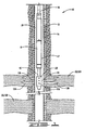
- FIG. 1 schematically shows a stimulation tool disposed in a well.
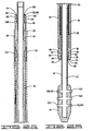
- FIGS. 2A and 2B are side cross-sectional views of the tool in an extended position to the inventive tool.
- FIGS. 3A and 3B are side cross-sectional views of the tool in a retracted position to the inventive tool.
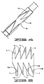
- FIG. 4 is a perspective view of the stem of the tool.
- FIG. 5 is a rolled-out exterior view of the stem of the tool.
- FIG. 6 is a cross-sectional view of the lower end of the tool.
- FIG. 7 is a detail view from FIG. 6 showing the gap between the stem and the housing, and showing seals installed in grooves in the housing.
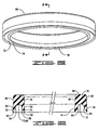
- FIG. 8 is a perspective view of a wiper seal.
- FIG. 9 is a cross-sectional view of the wiper seal taken along line 9-9.
- a well 10 comprising a wellbore 12, with a casing 14 cemented therein, is shown.
- a tool string 16 is shown positioned in well 10.
- Tool string 16 includes stimulation tool 17, which may comprise housing, or sealed sub 18 with jetting tool 20 extending therefrom.
- jetting tool 20 is positioned adjacent one of a plurality of formations, or zones, 22 intersected by well 10. It is understood that while stimulation tool 17 is shown in cased well 10, it may be used in open wellbores as well.
- Tool string 16 and casing 14 define annulus 21 therebetween.
- sealed sub 18 comprises upper end 24 and lower end 26.
- Sealed sub 18 has an inner surface 28 defining sub passage 30 therethrough.
- Sealed sub 18 defines at least one, and preferably a plurality of upper grooves or channels 32 with at least one, and preferably a plurality of upper seals 34 disposed therein.
- Sealed sub 18 has at least one, and preferably a plurality of lower channels 36 having at least one, and preferably a plurality of lower seals 38 disposed therein.
- Upper and lower seals 34 and 38 are described in more detail hereinbelow.
- Jetting tool 20, which comprises stem 42 and jetting head 44, is slidably disposed in sealed sub 18.
- Stem 42 defines a stem passage 43 therethrough.
- Stem 42, and thus jetting tool 20 is slidable relative to sealed sub 18, and is rotatable relative thereto.
- Upper and lower seals 34 and 38 sealingly engage stem 42, so that stem 42 and sealed sub 18 define a sealed, oil-filled cavity 46.
- a spring 48 is disposed about stem 42 in cavity 46, and is positioned between a shoulder 50, referred to herein as upper shoulder 50, defined on stem 42, and a lower shoulder 52.
- Lower shoulder 52 may be defined by an upper end 54 of a threaded lower end cap 56.
- Threaded lower end cap 56 comprises lower end 26 of sealed sub 18, and lower seals 38 are disposed in threaded lower end cap 56.
- Spring 48 biases stem 42 upwardly, as viewed in FIGS. 2A and 2B , to urge jetting tool 20 from its second, or extended position shown in FIGS. 2A and 2B , to its first, or retracted position shown in FIGS. 3A and 3B .
- the plurality of lower channels 36 comprise a lowermost channel 58 which may be referred to as first lower channel 58, and second, third and fourth lower channels 60, 62 and 64, respectively.
- Lowermost channel 58 has a wiper seal 66 disposed therein. Sealed sub 18 and stem 42 define a gap 68 therebetween at lower end 26 of sealed sub 18 so that well 10 communicates with channel 58 through gap, or passageway 68.
- Wiper seal 66 comprises body 70, with a cutaway portion 72 to define inner and outer wipers 74 and 76.
- Wiper seal 66 has inner side 78 and outer side 80.
- Wiper segments 82 and 84 respectively, that angle outwardly from generally vertical segments 81 and 83 define wipers 74 and 76.
- Cutaway portion 72 comprises an arcuate cutout 86, which may generally be a semicircular cutout 86 with ends 88 and 90. Cutaway portion 72 has angularly outwardly extending segments 92 and 94, which extend angularly outwardly from ends 88 and 90, and along with segments 82 and 84 define wipers 74 and 76.
- a wiper seal 66 is positioned in lowermost channel 58 so that cutaway portion 72 faces downwardly toward passageway 68 and well 10.
- a wiper seal 66 is also positioned in channel 60 and is oriented identically to the wiper seal in channel 58.
- Seals 66 are elastomeric, but may be formed of any seal material capable of withstanding downhole environments.
- An O-ring seal 96 is disposed in channel 62, and a third wiper seal 66 is positioned in channel 64.
- the wiper seal positioned in channel 64 has cutaway portion 72 facing upwardly, toward oil-filled cavity 46.
- the plurality of seals 38 comprise the three wiper seals 66 and one O-ring 96. Wiper seals 66 are compressed in channels 58, 60 and 64 between sealed sub 18 and stem 42, and sealingly engage both.
- the seal arrangement at upper end 24 of sealed sub 18 is a mirror image of the arrangement at lower end 26.
- Upper channels 32 may therefore comprise an uppermost channel 100, which may be referred to as a first upper channel 100, and second, third and fourth upper channels 102, 104 and 106, respectively.
- Wiper seals 66 positioned so that the cutaway portion 72 faces upwardly toward well 10 are disposed in channels 100 and 102 and a wiper seal 66 is positioned in channel 106 and faces downwardly, towards oil-filled cavity 46.
- An O-ring seal 96 is disposed in third upper channel 104.
- the plurality of seals 34 thus comprises the three wiper seals 66 and an O-ring seal 96.
- a gap, or passageway 109 similar to gap 68 at lower end 26 of sealed sub 18, is defined by sealed sub 18 and jetting tool 20 at upper end 24 of sealed sub 18.
- Well 10 communicates with uppermost channel 100 through passageway 109.
- Stimulation tool 17 includes a ratchet 110.
- Ratchet 110 comprises at least one, and preferably a pair of lugs 112 affixed to sealed sub 18, and a J-slot 114 in stem 42.
- Lugs 112 may be welded, or affixed by other means known in the art to sealed sub 18.
- J-slot 114 which is laid out in FIG. 5 , may be machined or otherwise formed in the stem 42, or may be machined or formed in a separate collar that is attached to stem 42.
- Lugs 112 may be referred to as lugs 112a and 112b which are positioned 180° apart.
- Stem 42 is movable relative to sealed sub 18, and ratcheting occurs when stem 42 is reciprocated axially relative to sealed sub 18, and the reciprocating motion causes stem 42 to rotate relative to sealed sub 18.
- Jetting head 44 has central passage 116 which is communicated with stem passage 43, and a plurality of ports 118 intersecting central passage 116, so that fluid may be communicated therethrough into well 10.
- Ports 118 comprise a first set of ports 120, and a second set of ports 122.
- the ports in each of first and second sets 120 and 122 are axially aligned, and first set 120 is positioned 180° from second set 122.
- Each of ports 118 may have a nozzle 123 therein such that ports 118 comprise jets, or jetting ports for jetting fluid into well 10. Other port positions and orientations may be used.
- tool string 16 with stimulation tool 17 is lowered into well 10 and positioned adjacent a first zone, for example first zone 124, to be treated. Fluid may be circulated into well 10 as tool string 16 is lowered therein. As stimulation tool 17 is lowered into well 10, lugs 112a and 112b will be positioned as shown by the solid lines in FIG. 5 and designated as position A in which stimulation tool 17 is in its retracted position. Once stimulation tool 17 reaches the desired position in the well adjacent first zone 124, fluid flow is increased inside tool string 16 such that a sufficient hydraulic pressure is applied to cause jetting tool 20 to move axially relative to sealed sub 18.
- the axial reciprocation will cause rotation of jetting tool 20 relative to sealed sub 18 as lugs 112a and 112b engage J-slot 114 and move from the position designated by the capital letter A to the position designated by the capital letter B.
- the axial motion and the rotation is thus caused solely by hydraulic pressure in the tool string which acts upon jetting tool 20 to move jetting tool 20 relative to sealed sub 18.
- Fluid is pumped from tool string 16 through stem passage 43, central passage 116 of jetting head 44, and through jetting ports 118 to perforate casing 14 in well 10 and to initiate and extend fractures in zone 124.
- the embodiment shown includes casing 14 but the method and tool described herein may be used in open uncased holes as well.
- the initial fluid pumped through jetting tool 20 comprises a first tubing fluid which is preferably a proppant-laden fluid.
- Well 10 may also have an initial annulus fluid which may be referred to as a first annulus fluid therein that fills annulus 21.
- the initial annulus fluid is preferably a clean fluid with no proppant, but may be otherwise.
- Pressure may be applied to the first annulus fluid so that pressure is applied to zone 124 both by the first annulus fluid and the first tubing fluid jetted through ports 120 and 122.
- fractures may be further extended with a pad or a second tubing fluid behind the proppant-laden fluid in the tool string 16. Pressure will continue to be applied by the first annulus fluid.
- treatment may continue.
- a third annulus fluid such as for example clean fluid may be pumped down tool string 16 while a proppant-laden fluid is pumped into annulus 21 to continue to extend fractures.
- a different method may be utilized so that a clean fluid is pumped in the annulus but a proppant-laden fluid is pumped through the jetting tool 20 after the pad.
- the fractures 126 schematically represent fractures that may occur during treatment at a first radial position in the well in the desired zone, in this case zone 124.
- jetting tool 20 may be rotated to a new or second radial position reflected in FIG. 1 by the position of the jetting head 44 in which the jetting ports 118 are shown perpendicular to the plane of the page.
- pressure in the tool string 16 is relieved to allow jetting head 20 to move upwardly relative to sealed sub 18 to the retracted position and to rotate due to engagement of lugs 112a and 112b with J-slot 114.
- Lugs 112 will be in position C on FIG. 5 . Pressure is then increased so that jetting head 20 will again move to its extended position and the reciprocating motion of jetting head 20 causes the engagement of lugs 112a and 112b with J-slot 114 to rotate jetting head 20 relative to sealed sub 18 to position D which is 90° from the position of jetting head 20 when the lugs are in position B.
- the treatment process as explained herein can then be performed at the second radial position at zone 124. Such treatment may occur at the same axial position in the well in zone 124 or if desired tool string 16 may be lifted or lowered so that the treatment at the second radial location is axially offset from the treatment at the first radial location.
- pressure can be decreased to allow jetting tool 20 to move to its retracted position.
- Tool string 16 can then be moved in well 10 to a second desired zone which may be a second zone such as second zone 128 that constitutes either a separate formation or a zone in the same formation in which prior treatment occurred.
- the treatment process as herein described may be performed at the second and other zones so that stimulation tool 17 may be utilized to perform the method described herein at a plurality of locations in a single well.
- jetting tool 20 can be rotated quickly and efficiently to allow treatment at different radial locations in a well. This is an advancement over prior art methods which generally require attempting to rotate the end of a tool by rotating the top of the tool string. Conversely, rotation of the jetting tool 20 described herein occurs with the ratcheting of the tool.
- the reciprocation of the jetting tool 20 which is translated into rotation by the reaction of lugs 112 with J-slot 114 occurs solely upon the application of hydraulic pressure sufficient to cause the extension of the jetting tool 20 relative to sealed sub 18.
- wiper seals 66 prevent contamination or at least reduce the possibility of contamination of the sealed sub 18 thus reducing the risk of clogging.
- wiper seals 66 and their relationship to gaps 68 and 109 operate to lessen any risk of contamination.
- fluid and thus proppant or other debris in well 10 may be drawn into or otherwise may be communicated into channels 58 and 100 through gap 68 at lower end 26 and through gap 109 at upper end 24 of sealed sub 18.
- Wipers 74 and 76 will wipe stem 42 as it reciprocates in sealed sub 18.
- cutaway portion 72 is shaped such that fluid and any proppant or debris that moves into lowermost channel 58 or uppermost channel 100 will be expelled therefrom through gaps 68 and 109, respectively.
Abstract
Description
- This disclosure relates to a system for treating a subterranean well formation to stimulate production, and more particularly to an apparatus and method for fracturing.
- Hydraulic fracturing is used often to stimulate production of hydrocarbons from formations penetrated by the wells. Typically, a well casing, if present, will be perforated adjacent the zone to be treated. Several zones may be treated, and a zone may comprise a formation, or several zones may be treated in a single formation. After the casing is perforated, a fracturing fluid is pumped into the well through the perforations so that fractures are formed and extended in the formation. Propping agents suspended in the fracturing fluid will be deposited in the fractures to prevent the fractures from closing.
- One method for fracturing involves using a jetting tool with jets, or ports, therethrough which can be used to initiate and extend fractures in a zone. It is often desirable to rotate the jetting tool so that fluid pumped through the jets acts on a zone at the same, or near the same longitudinal or axial location in the well but at a different radial location. In other words, fluid will be pumped through the jets to act on a zone in the well, and the tool will be rotated so that the jets are oriented at a different radial location in the well, but may be at the same or near the same axial location in the well.
- Typically, to rotate the jetting tool, the entire tool string must be moved. As such, it is difficult, time-consuming, and sometimes not possible to rotate the jetting tool and accurately position the jetting tool radially and axially in the well. A tool that can be consistently and accurately rotated and positioned in a well for accurate placement of fractures is desirable.
US 2006/070740 (A ) describes a system and method for fracturing a hydrocarbon producing formation in which a fracturing tool is inserted in a wellbore adjacent the formation, and fracturing fluid is introduced into the annulus between the fracturing tool and the wellbore and flows to the formation.
US 4799554 (A ) describes an apparatus for pressurized cleaning of flow conductors. The apparatus has a first mandrel and a second mandrel telescoped therein. A cleaning tool can be attached to the second mandrel. Changes in fluid pressure flowing through the mandrels will cause the second mandrel to rotate relative to the first mandrel. Rotation is used to direct fluid jets in the cleaning tool towards different portions of the interior of the flow conductor. Rotation of the cleaning tool can also be used for hydraulic drilling of deposits within the flow conductor. - A stimulation tool for treating zones intersected by a wellbore is disclosed. The stimulation tool may be lowered into the well on a tool string. The stimulation tool comprises a sealed sub, or outer housing with a jetting tool movable relative thereto. The jetting tool comprises a stem slidably disposed in the sealed sub with a jetting head connected at an end of the stem. The jetting tool is thus movable relative to the outer housing and to the tool string on which the stimulation tool is lowered.
- The stimulation tool is lowered into the well and is positioned adjacent a zone to be treated. The jetting tool is axially extended by applying hydraulic pressure with fluid through the tool string. The jetting tool will rotate simultaneous to its axial movement and will be positioned adjacent a first radial position in the well to be treated. The treatment may comprise, for example, pumping a proppant-laden fluid through the jetting head which may perforate any casing in the well and will initiate and begin to extend fractures in the zone. The jetting head preferably has ports with nozzles therein so that adequate velocity may be generated to perforate a casing if necessary and to initiate and extend fractures. An annulus fluid may be pumped in an annulus between the tool string and the well to aid in extending the fractures. The annulus fluid may be for example a clean fluid. Fractures may be created and extended further by, for example, pushing the proppant-laden fluid into the zone with a clean fluid behind the proppant-laden fluid, in the tool string which may be referred to as a pad. Thereafter, a proppant-laden fluid may be forced into the zone through the annulus or behind the pad in the tool string and through the jets. If the proppant-laden fluid is utilized in the annulus, it is preferred that a clean fluid continue to be pumped through the jetting tool. Likewise, if a proppant-laden fluid follows the clean fluid in the tool string, it is preferred that the annulus fluid be a clean fluid with no proppant therein.
- Once treatment at the first radial location is completed, the jetting tool is ratcheted so that it is positioned in a second radial location. The ratcheting involves relieving pressure in the tool string such that the jetting tool will axially retract and will simultaneously rotate to a retracted position. Hydraulic pressure is then applied by increasing the fluid flow into the jetting head to a sufficient level such that the jetting head will axially extend and will simultaneously rotate to the second radial position where treatment can then be applied. The treatment may be, for example, that described herein such that fractures are initiated and created at the second radial location. The jetting tool will move automatically from the extended to the retracted position upon the release of hydraulic pressure. The jetting tool is urged toward the retracted position by a spring disposed about the stem.
- If desired, several zones which may be several zones in a formation or which may be separate formations may be treated in the manner described herein.
-
FIG. 1 schematically shows a stimulation tool disposed in a well. -
FIGS. 2A and 2B are side cross-sectional views of the tool in an extended position to the inventive tool. -
FIGS. 3A and 3B are side cross-sectional views of the tool in a retracted position to the inventive tool. -
FIG. 4 is a perspective view of the stem of the tool. -
FIG. 5 is a rolled-out exterior view of the stem of the tool. -
FIG. 6 is a cross-sectional view of the lower end of the tool. -
FIG. 7 is a detail view fromFIG. 6 showing the gap between the stem and the housing, and showing seals installed in grooves in the housing. -
FIG. 8 is a perspective view of a wiper seal. -
FIG. 9 is a cross-sectional view of the wiper seal taken along line 9-9. - Referring to the figures, and more particularly to
FIG. 1 , a well 10 comprising awellbore 12, with acasing 14 cemented therein, is shown. Atool string 16 is shown positioned in well 10.Tool string 16 includesstimulation tool 17, which may comprise housing, or sealedsub 18 withjetting tool 20 extending therefrom. InFIG. 1 ,jetting tool 20 is positioned adjacent one of a plurality of formations, or zones, 22 intersected by well 10. It is understood that whilestimulation tool 17 is shown in cased well 10, it may be used in open wellbores as well.Tool string 16 andcasing 14 defineannulus 21 therebetween. - Referring to
FIGS. 2 and3 , sealedsub 18 comprisesupper end 24 andlower end 26. Sealedsub 18 has aninner surface 28 definingsub passage 30 therethrough.Sealed sub 18 defines at least one, and preferably a plurality of upper grooves orchannels 32 with at least one, and preferably a plurality ofupper seals 34 disposed therein.Sealed sub 18 has at least one, and preferably a plurality oflower channels 36 having at least one, and preferably a plurality oflower seals 38 disposed therein. Upper andlower seals tool 20, which comprisesstem 42 and jettinghead 44, is slidably disposed in sealedsub 18.Stem 42 defines astem passage 43 therethrough.Stem 42, and thus jettingtool 20, is slidable relative to sealedsub 18, and is rotatable relative thereto. Upper andlower seals stem 42, so thatstem 42 and sealedsub 18 define a sealed, oil-filledcavity 46. - A
spring 48 is disposed aboutstem 42 incavity 46, and is positioned between ashoulder 50, referred to herein asupper shoulder 50, defined onstem 42, and alower shoulder 52.Lower shoulder 52 may be defined by an upper end 54 of a threadedlower end cap 56. Threadedlower end cap 56 compriseslower end 26 of sealedsub 18, andlower seals 38 are disposed in threadedlower end cap 56.Spring 48 biases stem 42 upwardly, as viewed inFIGS. 2A and 2B , to urge jettingtool 20 from its second, or extended position shown inFIGS. 2A and 2B , to its first, or retracted position shown inFIGS. 3A and 3B . - The plurality of
lower channels 36 comprise alowermost channel 58 which may be referred to as firstlower channel 58, and second, third and fourthlower channels Lowermost channel 58 has awiper seal 66 disposed therein.Sealed sub 18 and stem 42 define agap 68 therebetween atlower end 26 of sealedsub 18 so that well 10 communicates withchannel 58 through gap, orpassageway 68. -
Wiper seal 66 comprisesbody 70, with acutaway portion 72 to define inner andouter wipers Wiper seal 66 hasinner side 78 andouter side 80.Wiper segments vertical segments wipers Cutaway portion 72 comprises an arcuate cutout 86, which may generally be a semicircular cutout 86 withends Cutaway portion 72 has angularly outwardly extendingsegments segments wipers - A
wiper seal 66 is positioned inlowermost channel 58 so thatcutaway portion 72 faces downwardly towardpassageway 68 and well 10. In the embodiment shown, awiper seal 66 is also positioned inchannel 60 and is oriented identically to the wiper seal inchannel 58.Seals 66 are elastomeric, but may be formed of any seal material capable of withstanding downhole environments. - An O-
ring seal 96 is disposed inchannel 62, and athird wiper seal 66 is positioned inchannel 64. The wiper seal positioned inchannel 64 hascutaway portion 72 facing upwardly, toward oil-filledcavity 46. Thus, in the embodiment shown, the plurality ofseals 38 comprise the threewiper seals 66 and one O-ring 96. Wiper seals 66 are compressed inchannels sub 18 andstem 42, and sealingly engage both. - The seal arrangement at
upper end 24 of sealedsub 18 is a mirror image of the arrangement atlower end 26.Upper channels 32 may therefore comprise anuppermost channel 100, which may be referred to as a firstupper channel 100, and second, third and fourthupper channels cutaway portion 72 faces upwardly toward well 10 are disposed inchannels wiper seal 66 is positioned inchannel 106 and faces downwardly, towards oil-filledcavity 46. An O-ring seal 96 is disposed in thirdupper channel 104. The plurality ofseals 34 thus comprises the threewiper seals 66 and an O-ring seal 96. A gap, orpassageway 109, similar togap 68 atlower end 26 of sealedsub 18, is defined by sealedsub 18 and jettingtool 20 atupper end 24 of sealedsub 18. Well 10 communicates withuppermost channel 100 throughpassageway 109. -
Stimulation tool 17 includes a ratchet 110. Ratchet 110 comprises at least one, and preferably a pair oflugs 112 affixed to sealedsub 18, and a J-slot 114 instem 42.Lugs 112 may be welded, or affixed by other means known in the art to sealedsub 18. J-slot 114, which is laid out inFIG. 5 , may be machined or otherwise formed in thestem 42, or may be machined or formed in a separate collar that is attached to stem 42. -
Lugs 112 may be referred to aslugs Stem 42 is movable relative to sealedsub 18, and ratcheting occurs whenstem 42 is reciprocated axially relative to sealedsub 18, and the reciprocating motion causes stem 42 to rotate relative to sealedsub 18. - The axial motion of
stem 42 relative to sealedsub 18, and the rotation ofstem 42 relative to sealedsub 18 occur solely upon the application and relief of hydraulic pressure, due to fluid flow intool string 16 into and through jettingtool 20. - Jetting
head 44 hascentral passage 116 which is communicated withstem passage 43, and a plurality ofports 118 intersectingcentral passage 116, so that fluid may be communicated therethrough into well 10.Ports 118 comprise a first set of ports 120, and a second set of ports 122. In the embodiment shown, the ports in each of first and second sets 120 and 122 are axially aligned, and first set 120 is positioned 180° from second set 122. Each ofports 118 may have anozzle 123 therein such thatports 118 comprise jets, or jetting ports for jetting fluid into well 10. Other port positions and orientations may be used. - In operation,
tool string 16 withstimulation tool 17 is lowered into well 10 and positioned adjacent a first zone, for example first zone 124, to be treated. Fluid may be circulated into well 10 astool string 16 is lowered therein. Asstimulation tool 17 is lowered into well 10, lugs 112a and 112b will be positioned as shown by the solid lines inFIG. 5 and designated as position A in whichstimulation tool 17 is in its retracted position. Oncestimulation tool 17 reaches the desired position in the well adjacent first zone 124, fluid flow is increased insidetool string 16 such that a sufficient hydraulic pressure is applied to cause jettingtool 20 to move axially relative to sealedsub 18. - The axial reciprocation will cause rotation of jetting
tool 20 relative to sealedsub 18 aslugs slot 114 and move from the position designated by the capital letter A to the position designated by the capital letter B. The axial motion and the rotation is thus caused solely by hydraulic pressure in the tool string which acts upon jettingtool 20 to move jettingtool 20 relative to sealedsub 18. Fluid is pumped fromtool string 16 throughstem passage 43,central passage 116 of jettinghead 44, and through jettingports 118 to perforatecasing 14 in well 10 and to initiate and extend fractures in zone 124. As explained above, the embodiment shown includescasing 14 but the method and tool described herein may be used in open uncased holes as well. The initial fluid pumped through jettingtool 20 comprises a first tubing fluid which is preferably a proppant-laden fluid. Well 10 may also have an initial annulus fluid which may be referred to as a first annulus fluid therein that fillsannulus 21. The initial annulus fluid is preferably a clean fluid with no proppant, but may be otherwise. - Pressure may be applied to the first annulus fluid so that pressure is applied to zone 124 both by the first annulus fluid and the first tubing fluid jetted through ports 120 and 122. In one embodiment, fractures may be further extended with a pad or a second tubing fluid behind the proppant-laden fluid in the
tool string 16. Pressure will continue to be applied by the first annulus fluid. After the pad is pumped through thetool string 16, treatment may continue. For example, a third annulus fluid, such as for example clean fluid may be pumped downtool string 16 while a proppant-laden fluid is pumped intoannulus 21 to continue to extend fractures. If desired, a different method may be utilized so that a clean fluid is pumped in the annulus but a proppant-laden fluid is pumped through the jettingtool 20 after the pad. - In
FIG. 1 , thefractures 126 schematically represent fractures that may occur during treatment at a first radial position in the well in the desired zone, in this case zone 124. Once that treatment is complete, jettingtool 20 may be rotated to a new or second radial position reflected inFIG. 1 by the position of the jettinghead 44 in which the jettingports 118 are shown perpendicular to the plane of the page. To rotate from the first radial position to the second radial position, which is 90° from the first radial position, pressure in thetool string 16 is relieved to allow jettinghead 20 to move upwardly relative to sealedsub 18 to the retracted position and to rotate due to engagement oflugs slot 114.Lugs 112 will be in position C onFIG. 5 . Pressure is then increased so that jettinghead 20 will again move to its extended position and the reciprocating motion of jettinghead 20 causes the engagement oflugs slot 114 to rotate jettinghead 20 relative to sealedsub 18 to position D which is 90° from the position of jettinghead 20 when the lugs are in position B. The treatment process as explained herein can then be performed at the second radial position at zone 124. Such treatment may occur at the same axial position in the well in zone 124 or if desiredtool string 16 may be lifted or lowered so that the treatment at the second radial location is axially offset from the treatment at the first radial location. Once the treatment process at the second radial location is complete, pressure can be decreased to allow jettingtool 20 to move to its retracted position.Tool string 16 can then be moved in well 10 to a second desired zone which may be a second zone such as second zone 128 that constitutes either a separate formation or a zone in the same formation in which prior treatment occurred. The treatment process as herein described may be performed at the second and other zones so thatstimulation tool 17 may be utilized to perform the method described herein at a plurality of locations in a single well. - As is apparent, jetting
tool 20 can be rotated quickly and efficiently to allow treatment at different radial locations in a well. This is an advancement over prior art methods which generally require attempting to rotate the end of a tool by rotating the top of the tool string. Conversely, rotation of the jettingtool 20 described herein occurs with the ratcheting of the tool. The reciprocation of the jettingtool 20 which is translated into rotation by the reaction oflugs 112 with J-slot 114 occurs solely upon the application of hydraulic pressure sufficient to cause the extension of the jettingtool 20 relative to sealedsub 18. In addition to the quick and efficient rotation of the jettingtool 20, wiper seals 66 prevent contamination or at least reduce the possibility of contamination of the sealedsub 18 thus reducing the risk of clogging. - The design and orientation of wiper seals 66 and their relationship to
gaps tool 20, fluid and thus proppant or other debris in well 10 may be drawn into or otherwise may be communicated intochannels gap 68 atlower end 26 and throughgap 109 atupper end 24 of sealedsub 18.Wipers stem 42 as it reciprocates in sealedsub 18. In addition,cutaway portion 72 is shaped such that fluid and any proppant or debris that moves intolowermost channel 58 oruppermost channel 100 will be expelled therefrom throughgaps stem 42 along with the shape of wiper seals 66 cause circulation of any fluid that enters thegaps wiper seal 66 and migrating into the oil-filledcavity 46. Wiper seals 66 adjacent the oil-filledcavity 46 are oriented oppositely to help prevent the escape of any oil and to maintain the integrity of oil in thecavity 46. - Thus, it is seen that the apparatus and methods of the present invention readily achieve the ends and advantages mentioned as well as those inherent therein. While certain preferred embodiments of the invention have been illustrated and described for purposes of the present disclosure, numerous changes in the arrangement and construction of parts and steps may be made by those skilled in the art, which changes are encompassed within the scope of the .. present invention as defined by the appended claims.
Claims (14)
- A method of treating a well (10) comprising:(a) positioning a stimulation tool (17) on a tool string (16) in the well adjacent a first zone (124) to be treated;(b) axially extending the stimulation tool (17) relative to the tool string (16) and simultaneously rotating a jetting tool (20) to a first radial position adjacent the first zone (124);(c) pumping a proppant-laden fluid through the stimulation tool (17) to initiate fractures in the first zone (124);
characterized by(d) ratcheting the stimulation tool (17) to a second radial position adjacent the first zone; and(e) pumping a proppant-laden fluid through the stimulation tool (17) to initiate fractures in the first zone at the second radial position; wherein the stimulation tool (17) comprises:a sealed sub (18) having a stem (42) slidably disposed therethrough with a jetting head (44) on an end thereof; anda lowermost seal disposed in a lowermost channel (58) on the sealed sub (18), the sealed sub (18) and stem (42) defining a gap (68) therebetween at a lower end thereof which communicates the well with the lowermost channel. - The method of claim 1, further comprising positioning the stimulation tool (17) adjacent a second zone (128) to be treated in the well (10) and repeating steps (b), (c), (d) and (e) of claim 1 for the second zone.
- The method of claim 1, further comprising pumping an annulus fluid in an annulus (21) between the tool string (16) and a casing (14) in the well into the first zone.
- The method of claim 3, wherein the annulus fluid is selected from the group consisting of a proppant-laden fluid and a clean fluid.
- The method of claim 1, wherein during the ratcheting step well debris is communicated into the gap and is expelled therefrom by the lowermost seal.
- The method of claim 1, the ratcheting step comprising:axially retracting the jetting head (44) relative to the tool string (16) and simultaneously rotating the jetting head relative to the tool string; andaxially extending the jetting head (44) relative to the tool string (16) and simultaneously rotating the jetting head to the second radial position.
- The method of claim 6, the axially extending steps comprising applying sufficient hydraulic pressure in the tool string (16) to cause the jetting head (44) to axially extend, the axially retracting step comprising reducing the hydraulic pressure in the tool string to automatically axially retract the jetting head.
- A clog-resistant stimulation tool (17) comprising:a sealed sub (18);a stem (42) slidably disposed in the sealed sub (18);a jetting head (44) connected to the stem (42), the stem and jetting head being movable axially and rotationally relative to the sealed sub(18); anda seal (66) disposed in a lowermost channel (58) on the sealed sub, characterized by the sealed sub (18) and stem (42) defining a gap (68) therebetween at a lower end thereof which will communicate a well (10) in which the tool is disposed with the lowermost channel, wherein debris will be drawn into, and expelled from the lowermost channel as the stem moves axially relative to the sealed sub.
- The clog-resistant stimulation tool of claim 8, further comprising a ratchet (110) coupled to the stem (42).
- The clog-resistant tool of claim 9, wherein the ratchet comprises a J-slot (114) and a lug (112) coupled together, the J-slot formed in the stem and the lug affixed to the sealed sub.
- The clog-resistant stimulation tool of claim 8, wherein the seal (66) in the lowermost channel (58) comprises a lowermost seal, the lowermost seal having an arcuate cutout oriented towards the gap at the lower end of the sealed sub (18), the tool further comprising an uppermost seal disposed in an uppermost channel (100) defined in the sealed sub (18), the sealed sub and the stem defining a gap (109) therebetween at the upper end of the sealed sub, the uppermost seal being substantially identical to the lowermost seal and oriented oppositely from the lowermost seal, so that the arcuate cutout in the uppermost seal is oriented towards the gap at the upper end of the sealed sub.
- The stimulation tool of claim 8, wherein the jetting head (44) will axially extend relative to the sealed sub (18) to an extended position solely upon the application of hydraulic pressure from fluid communicated through the stem (42) to the jetting head (44), and will automatically axially retract to a retracted position when hydraulic pressure is reduced.
- The stimulation tool of claim 12, further comprising a spring (48) disposed about the stem (42), wherein the spring biases the stem towards the retracted position.
- The stimulation tool of claim 12, wherein as the stem (42) moves axially relative to the sealed sub (18) well debris is drawn into and expelled from the uppermost and lowermost channels (58, 100) through the gaps (68, 109) at the upper and lower ends, respectively, of the sealed sub (18).
Applications Claiming Priority (2)
| Application Number | Priority Date | Filing Date | Title |
|---|---|---|---|
| US11/977,772 US7726403B2 (en) | 2007-10-26 | 2007-10-26 | Apparatus and method for ratcheting stimulation tool |
| PCT/GB2008/003401 WO2009053669A1 (en) | 2007-10-26 | 2008-10-09 | Apparatus and method for ratcheting stimulation tool |
Publications (2)
| Publication Number | Publication Date |
|---|---|
| EP2201212A1 EP2201212A1 (en) | 2010-06-30 |
| EP2201212B1 true EP2201212B1 (en) | 2012-01-04 |
Family
ID=40251550
Family Applications (1)
| Application Number | Title | Priority Date | Filing Date |
|---|---|---|---|
| EP08806541A Not-in-force EP2201212B1 (en) | 2007-10-26 | 2008-10-09 | Apparatus and method for ratcheting stimulation tool |
Country Status (9)
| Country | Link |
|---|---|
| US (1) | US7726403B2 (en) |
| EP (1) | EP2201212B1 (en) |
| AT (1) | ATE540195T1 (en) |
| AU (1) | AU2008315781B2 (en) |
| BR (1) | BRPI0819084A2 (en) |
| CA (1) | CA2701909C (en) |
| MX (1) | MX2010003890A (en) |
| RU (1) | RU2432451C1 (en) |
| WO (1) | WO2009053669A1 (en) |
Families Citing this family (40)
| Publication number | Priority date | Publication date | Assignee | Title |
|---|---|---|---|---|
| US7647966B2 (en) | 2007-08-01 | 2010-01-19 | Halliburton Energy Services, Inc. | Method for drainage of heavy oil reservoir via horizontal wellbore |
| US7832477B2 (en) | 2007-12-28 | 2010-11-16 | Halliburton Energy Services, Inc. | Casing deformation and control for inclusion propagation |
| US8960292B2 (en) | 2008-08-22 | 2015-02-24 | Halliburton Energy Services, Inc. | High rate stimulation method for deep, large bore completions |
| US8439116B2 (en) | 2009-07-24 | 2013-05-14 | Halliburton Energy Services, Inc. | Method for inducing fracture complexity in hydraulically fractured horizontal well completions |
| US8631872B2 (en) | 2009-09-24 | 2014-01-21 | Halliburton Energy Services, Inc. | Complex fracturing using a straddle packer in a horizontal wellbore |
| US8887803B2 (en) | 2012-04-09 | 2014-11-18 | Halliburton Energy Services, Inc. | Multi-interval wellbore treatment method |
| US9796918B2 (en) | 2013-01-30 | 2017-10-24 | Halliburton Energy Services, Inc. | Wellbore servicing fluids and methods of making and using same |
| US9016376B2 (en) | 2012-08-06 | 2015-04-28 | Halliburton Energy Services, Inc. | Method and wellbore servicing apparatus for production completion of an oil and gas well |
| US8261761B2 (en) | 2009-05-07 | 2012-09-11 | Baker Hughes Incorporated | Selectively movable seat arrangement and method |
| US8272445B2 (en) | 2009-07-15 | 2012-09-25 | Baker Hughes Incorporated | Tubular valve system and method |
| US8251154B2 (en) | 2009-08-04 | 2012-08-28 | Baker Hughes Incorporated | Tubular system with selectively engagable sleeves and method |
| US8291988B2 (en) | 2009-08-10 | 2012-10-23 | Baker Hughes Incorporated | Tubular actuator, system and method |
| US8397823B2 (en) | 2009-08-10 | 2013-03-19 | Baker Hughes Incorporated | Tubular actuator, system and method |
| US8291980B2 (en) | 2009-08-13 | 2012-10-23 | Baker Hughes Incorporated | Tubular valving system and method |
| US8479823B2 (en) | 2009-09-22 | 2013-07-09 | Baker Hughes Incorporated | Plug counter and method |
| US8418769B2 (en) | 2009-09-25 | 2013-04-16 | Baker Hughes Incorporated | Tubular actuator and method |
| US8316951B2 (en) | 2009-09-25 | 2012-11-27 | Baker Hughes Incorporated | Tubular actuator and method |
| US8646531B2 (en) | 2009-10-29 | 2014-02-11 | Baker Hughes Incorporated | Tubular actuator, system and method |
| CA2693676C (en) * | 2010-02-18 | 2011-11-01 | Ncs Oilfield Services Canada Inc. | Downhole tool assembly with debris relief, and method for using same |
| US9279311B2 (en) * | 2010-03-23 | 2016-03-08 | Baker Hughes Incorporation | System, assembly and method for port control |
| US8365827B2 (en) | 2010-06-16 | 2013-02-05 | Baker Hughes Incorporated | Fracturing method to reduce tortuosity |
| US8789600B2 (en) | 2010-08-24 | 2014-07-29 | Baker Hughes Incorporated | Fracing system and method |
| US8662162B2 (en) | 2011-02-03 | 2014-03-04 | Baker Hughes Incorporated | Segmented collapsible ball seat allowing ball recovery |
| US8939202B2 (en) | 2011-05-24 | 2015-01-27 | Baker Hughes Incorporated | Fracturing nozzle assembly with cyclic stress capability |
| US8720544B2 (en) | 2011-05-24 | 2014-05-13 | Baker Hughes Incorporated | Enhanced penetration of telescoping fracturing nozzle assembly |
| US8955585B2 (en) | 2011-09-27 | 2015-02-17 | Halliburton Energy Services, Inc. | Forming inclusions in selected azimuthal orientations from a casing section |
| AU2012322860A1 (en) * | 2011-10-12 | 2014-05-29 | Schlumberger Technology B.V. | Hydraulic fracturing with proppant pulsing through clustered abrasive perforations |
| US8931559B2 (en) | 2012-03-23 | 2015-01-13 | Ncs Oilfield Services Canada, Inc. | Downhole isolation and depressurization tool |
| WO2013181229A2 (en) | 2012-05-29 | 2013-12-05 | Saudi Arabian Oil Company | Enhanced oil recovery by in-situ steam generation |
| US8899337B2 (en) * | 2012-09-10 | 2014-12-02 | Halliburton Energy Services, Inc. | Method and apparatus for securing and using hyrdajetting tools |
| WO2015163879A1 (en) * | 2014-04-24 | 2015-10-29 | Halliburton Energy Services, Inc. | Multi-perforating tool |
| CN106545324A (en) * | 2015-09-18 | 2017-03-29 | 中国石油化工股份有限公司 | A kind of method for pressing off the multiple horizontal bedding seams of shale gas |
| CN108350349A (en) | 2015-11-05 | 2018-07-31 | 沙特阿拉伯石油公司 | Exothermic reaction is triggered to reservoir using microwave |
| EP3371411B1 (en) | 2015-11-05 | 2021-02-17 | Saudi Arabian Oil Company | Methods and apparatus for spatially-oriented chemically-induced pulsed fracturing in reservoirs |
| WO2017119877A1 (en) * | 2016-01-06 | 2017-07-13 | Halliburton Energy Services, Inc. | Downhole hydraulic fracturing tool |
| US10407999B2 (en) | 2016-05-11 | 2019-09-10 | Extensive Energy Technologies Partnership | Vibration dampener |
| CN107227948A (en) * | 2017-05-19 | 2017-10-03 | 中国石油集团川庆钻探工程有限公司 | The method that ground controls downhole orientation hydrajet tool |
| CN109989737B (en) * | 2018-01-03 | 2021-09-10 | 中国石油化工股份有限公司 | Method for realizing self-supporting fracture of rock |
| EA034257B1 (en) * | 2018-07-26 | 2020-01-22 | Максим Ильдусович ХАКИМОВ | Hydromechanical opening device and turning mechanism for its implementation |
| CN109488272A (en) * | 2018-11-08 | 2019-03-19 | 重庆科技学院 | Hot dry rock vertical well cuts fracturing process |
Family Cites Families (21)
| Publication number | Priority date | Publication date | Assignee | Title |
|---|---|---|---|---|
| US3764168A (en) * | 1971-10-12 | 1973-10-09 | Schlumberger Technology Corp | Drilling expansion joint apparatus |
| US4625799A (en) * | 1985-06-19 | 1986-12-02 | Otis Engineering Corporation | Cleaning tool |
| US4799554A (en) * | 1987-04-10 | 1989-01-24 | Otis Engineering Corporation | Pressure actuated cleaning tool |
| US5361856A (en) * | 1992-09-29 | 1994-11-08 | Halliburton Company | Well jetting apparatus and met of modifying a well therewith |
| US5826661A (en) * | 1994-05-02 | 1998-10-27 | Halliburton Energy Services, Inc. | Linear indexing apparatus and methods of using same |
| US5533571A (en) * | 1994-05-27 | 1996-07-09 | Halliburton Company | Surface switchable down-jet/side-jet apparatus |
| US5499678A (en) * | 1994-08-02 | 1996-03-19 | Halliburton Company | Coplanar angular jetting head for well perforating |
| US5845711A (en) * | 1995-06-02 | 1998-12-08 | Halliburton Company | Coiled tubing apparatus |
| US5765642A (en) * | 1996-12-23 | 1998-06-16 | Halliburton Energy Services, Inc. | Subterranean formation fracturing methods |
| US5980446A (en) * | 1997-08-12 | 1999-11-09 | Lockheed Martin Idaho Technologies Company | Methods and system for subsurface stabilization using jet grouting |
| US6286599B1 (en) * | 2000-03-10 | 2001-09-11 | Halliburton Energy Services, Inc. | Method and apparatus for lateral casing window cutting using hydrajetting |
| GB0106538D0 (en) | 2001-03-15 | 2001-05-02 | Andergauge Ltd | Downhole tool |
| US6662874B2 (en) * | 2001-09-28 | 2003-12-16 | Halliburton Energy Services, Inc. | System and method for fracturing a subterranean well formation for improving hydrocarbon production |
| US6938690B2 (en) * | 2001-09-28 | 2005-09-06 | Halliburton Energy Services, Inc. | Downhole tool and method for fracturing a subterranean well formation |
| US6712134B2 (en) * | 2002-02-12 | 2004-03-30 | Baker Hughes Incorporated | Modular bi-directional hydraulic jar with rotating capability |
| US6948561B2 (en) * | 2002-07-12 | 2005-09-27 | Baker Hughes Incorporated | Indexing apparatus |
| US7096946B2 (en) * | 2003-12-30 | 2006-08-29 | Baker Hughes Incorporated | Rotating blast liner |
| US7225869B2 (en) | 2004-03-24 | 2007-06-05 | Halliburton Energy Services, Inc. | Methods of isolating hydrajet stimulated zones |
| US7159660B2 (en) * | 2004-05-28 | 2007-01-09 | Halliburton Energy Services, Inc. | Hydrajet perforation and fracturing tool |
| US20060070740A1 (en) * | 2004-10-05 | 2006-04-06 | Surjaatmadja Jim B | System and method for fracturing a hydrocarbon producing formation |
| US8336625B2 (en) * | 2004-11-03 | 2012-12-25 | Halliburton Energy Services, Inc. | Fracturing/gravel packing tool with variable direction and exposure exit ports |
-
2007
- 2007-10-26 US US11/977,772 patent/US7726403B2/en not_active Expired - Fee Related
-
2008
- 2008-10-09 WO PCT/GB2008/003401 patent/WO2009053669A1/en active Application Filing
- 2008-10-09 RU RU2010121141/03A patent/RU2432451C1/en not_active IP Right Cessation
- 2008-10-09 BR BRPI0819084 patent/BRPI0819084A2/en not_active Application Discontinuation
- 2008-10-09 EP EP08806541A patent/EP2201212B1/en not_active Not-in-force
- 2008-10-09 AT AT08806541T patent/ATE540195T1/en active
- 2008-10-09 CA CA2701909A patent/CA2701909C/en not_active Expired - Fee Related
- 2008-10-09 MX MX2010003890A patent/MX2010003890A/en active IP Right Grant
- 2008-10-09 AU AU2008315781A patent/AU2008315781B2/en not_active Ceased
Also Published As
| Publication number | Publication date |
|---|---|
| MX2010003890A (en) | 2010-05-14 |
| EP2201212A1 (en) | 2010-06-30 |
| US20090107680A1 (en) | 2009-04-30 |
| CA2701909A1 (en) | 2009-04-30 |
| BRPI0819084A2 (en) | 2015-04-22 |
| AU2008315781B2 (en) | 2013-06-27 |
| CA2701909C (en) | 2013-01-22 |
| RU2432451C1 (en) | 2011-10-27 |
| US7726403B2 (en) | 2010-06-01 |
| WO2009053669A1 (en) | 2009-04-30 |
| ATE540195T1 (en) | 2012-01-15 |
| AU2008315781A1 (en) | 2009-04-30 |
Similar Documents
| Publication | Publication Date | Title |
|---|---|---|
| EP2201212B1 (en) | Apparatus and method for ratcheting stimulation tool | |
| US9765607B2 (en) | Open hole fracing system | |
| US8931557B2 (en) | Wellbore servicing assemblies and methods of using the same | |
| US9303501B2 (en) | Method and apparatus for wellbore fluid treatment | |
| CA2225571C (en) | Subterranean formation fracturing methods | |
| CA2017640C (en) | Well completions | |
| US7926571B2 (en) | Cemented open hole selective fracing system | |
| US8616281B2 (en) | Method and apparatus for moving a high pressure fluid aperture in a well bore servicing tool | |
| US6286599B1 (en) | Method and apparatus for lateral casing window cutting using hydrajetting | |
| US20130248192A1 (en) | Multizone and zone-by-zone abrasive jetting tools and methods for fracturing subterranean formations | |
| US20060196667A1 (en) | Fracturing method providing simultaneous flow back | |
| WO2007129099A2 (en) | Perforating and fracturing | |
| US9284823B2 (en) | Combined perforating and fracking tool | |
| US8973661B2 (en) | Method of fracturing while drilling | |
| WO2016026024A1 (en) | Apparatus and method for treating a reservoir using re-closeable sleeves | |
| US20050133226A1 (en) | Modular hydrojetting tool |
Legal Events
| Date | Code | Title | Description |
|---|---|---|---|
| PUAI | Public reference made under article 153(3) epc to a published international application that has entered the european phase |
Free format text: ORIGINAL CODE: 0009012 |
|
| 17P | Request for examination filed |
Effective date: 20100329 |
|
| AK | Designated contracting states |
Kind code of ref document: A1 Designated state(s): AT BE BG CH CY CZ DE DK EE ES FI FR GB GR HR HU IE IS IT LI LT LU LV MC MT NL NO PL PT RO SE SI SK TR |
|
| AX | Request for extension of the european patent |
Extension state: AL BA MK RS |
|
| 17Q | First examination report despatched |
Effective date: 20100729 |
|
| DAX | Request for extension of the european patent (deleted) | ||
| GRAP | Despatch of communication of intention to grant a patent |
Free format text: ORIGINAL CODE: EPIDOSNIGR1 |
|
| GRAS | Grant fee paid |
Free format text: ORIGINAL CODE: EPIDOSNIGR3 |
|
| GRAA | (expected) grant |
Free format text: ORIGINAL CODE: 0009210 |
|
| AK | Designated contracting states |
Kind code of ref document: B1 Designated state(s): AT BE BG CH CY CZ DE DK EE ES FI FR GB GR HR HU IE IS IT LI LT LU LV MC MT NL NO PL PT RO SE SI SK TR |
|
| REG | Reference to a national code |
Ref country code: GB Ref legal event code: FG4D |
|
| REG | Reference to a national code |
Ref country code: CH Ref legal event code: EP |
|
| REG | Reference to a national code |
Ref country code: AT Ref legal event code: REF Ref document number: 540195 Country of ref document: AT Kind code of ref document: T Effective date: 20120115 |
|
| REG | Reference to a national code |
Ref country code: IE Ref legal event code: FG4D |
|
| REG | Reference to a national code |
Ref country code: DE Ref legal event code: R096 Ref document number: 602008012523 Country of ref document: DE Effective date: 20120308 |
|
| REG | Reference to a national code |
Ref country code: NL Ref legal event code: VDEP Effective date: 20120104 |
|
| REG | Reference to a national code |
Ref country code: NO Ref legal event code: T2 Effective date: 20120104 |
|
| PG25 | Lapsed in a contracting state [announced via postgrant information from national office to epo] |
Ref country code: SI Free format text: LAPSE BECAUSE OF FAILURE TO SUBMIT A TRANSLATION OF THE DESCRIPTION OR TO PAY THE FEE WITHIN THE PRESCRIBED TIME-LIMIT Effective date: 20120104 |
|
| LTIE | Lt: invalidation of european patent or patent extension |
Effective date: 20120104 |
|
| PG25 | Lapsed in a contracting state [announced via postgrant information from national office to epo] |
Ref country code: NL Free format text: LAPSE BECAUSE OF FAILURE TO SUBMIT A TRANSLATION OF THE DESCRIPTION OR TO PAY THE FEE WITHIN THE PRESCRIBED TIME-LIMIT Effective date: 20120104 Ref country code: BG Free format text: LAPSE BECAUSE OF FAILURE TO SUBMIT A TRANSLATION OF THE DESCRIPTION OR TO PAY THE FEE WITHIN THE PRESCRIBED TIME-LIMIT Effective date: 20120404 Ref country code: IS Free format text: LAPSE BECAUSE OF FAILURE TO SUBMIT A TRANSLATION OF THE DESCRIPTION OR TO PAY THE FEE WITHIN THE PRESCRIBED TIME-LIMIT Effective date: 20120504 Ref country code: HR Free format text: LAPSE BECAUSE OF FAILURE TO SUBMIT A TRANSLATION OF THE DESCRIPTION OR TO PAY THE FEE WITHIN THE PRESCRIBED TIME-LIMIT Effective date: 20120104 Ref country code: LT Free format text: LAPSE BECAUSE OF FAILURE TO SUBMIT A TRANSLATION OF THE DESCRIPTION OR TO PAY THE FEE WITHIN THE PRESCRIBED TIME-LIMIT Effective date: 20120104 Ref country code: BE Free format text: LAPSE BECAUSE OF FAILURE TO SUBMIT A TRANSLATION OF THE DESCRIPTION OR TO PAY THE FEE WITHIN THE PRESCRIBED TIME-LIMIT Effective date: 20120104 |
|
| PG25 | Lapsed in a contracting state [announced via postgrant information from national office to epo] |
Ref country code: PL Free format text: LAPSE BECAUSE OF FAILURE TO SUBMIT A TRANSLATION OF THE DESCRIPTION OR TO PAY THE FEE WITHIN THE PRESCRIBED TIME-LIMIT Effective date: 20120104 Ref country code: GR Free format text: LAPSE BECAUSE OF FAILURE TO SUBMIT A TRANSLATION OF THE DESCRIPTION OR TO PAY THE FEE WITHIN THE PRESCRIBED TIME-LIMIT Effective date: 20120405 Ref country code: PT Free format text: LAPSE BECAUSE OF FAILURE TO SUBMIT A TRANSLATION OF THE DESCRIPTION OR TO PAY THE FEE WITHIN THE PRESCRIBED TIME-LIMIT Effective date: 20120504 Ref country code: LV Free format text: LAPSE BECAUSE OF FAILURE TO SUBMIT A TRANSLATION OF THE DESCRIPTION OR TO PAY THE FEE WITHIN THE PRESCRIBED TIME-LIMIT Effective date: 20120104 Ref country code: FI Free format text: LAPSE BECAUSE OF FAILURE TO SUBMIT A TRANSLATION OF THE DESCRIPTION OR TO PAY THE FEE WITHIN THE PRESCRIBED TIME-LIMIT Effective date: 20120104 |
|
| REG | Reference to a national code |
Ref country code: AT Ref legal event code: MK05 Ref document number: 540195 Country of ref document: AT Kind code of ref document: T Effective date: 20120104 |
|
| PG25 | Lapsed in a contracting state [announced via postgrant information from national office to epo] |
Ref country code: CY Free format text: LAPSE BECAUSE OF FAILURE TO SUBMIT A TRANSLATION OF THE DESCRIPTION OR TO PAY THE FEE WITHIN THE PRESCRIBED TIME-LIMIT Effective date: 20120104 |
|
| PG25 | Lapsed in a contracting state [announced via postgrant information from national office to epo] |
Ref country code: EE Free format text: LAPSE BECAUSE OF FAILURE TO SUBMIT A TRANSLATION OF THE DESCRIPTION OR TO PAY THE FEE WITHIN THE PRESCRIBED TIME-LIMIT Effective date: 20120104 Ref country code: RO Free format text: LAPSE BECAUSE OF FAILURE TO SUBMIT A TRANSLATION OF THE DESCRIPTION OR TO PAY THE FEE WITHIN THE PRESCRIBED TIME-LIMIT Effective date: 20120104 Ref country code: CZ Free format text: LAPSE BECAUSE OF FAILURE TO SUBMIT A TRANSLATION OF THE DESCRIPTION OR TO PAY THE FEE WITHIN THE PRESCRIBED TIME-LIMIT Effective date: 20120104 Ref country code: SE Free format text: LAPSE BECAUSE OF FAILURE TO SUBMIT A TRANSLATION OF THE DESCRIPTION OR TO PAY THE FEE WITHIN THE PRESCRIBED TIME-LIMIT Effective date: 20120104 Ref country code: DK Free format text: LAPSE BECAUSE OF FAILURE TO SUBMIT A TRANSLATION OF THE DESCRIPTION OR TO PAY THE FEE WITHIN THE PRESCRIBED TIME-LIMIT Effective date: 20120104 |
|
| PLBE | No opposition filed within time limit |
Free format text: ORIGINAL CODE: 0009261 |
|
| STAA | Information on the status of an ep patent application or granted ep patent |
Free format text: STATUS: NO OPPOSITION FILED WITHIN TIME LIMIT |
|
| PG25 | Lapsed in a contracting state [announced via postgrant information from national office to epo] |
Ref country code: SK Free format text: LAPSE BECAUSE OF FAILURE TO SUBMIT A TRANSLATION OF THE DESCRIPTION OR TO PAY THE FEE WITHIN THE PRESCRIBED TIME-LIMIT Effective date: 20120104 Ref country code: IT Free format text: LAPSE BECAUSE OF FAILURE TO SUBMIT A TRANSLATION OF THE DESCRIPTION OR TO PAY THE FEE WITHIN THE PRESCRIBED TIME-LIMIT Effective date: 20120104 |
|
| 26N | No opposition filed |
Effective date: 20121005 |
|
| PG25 | Lapsed in a contracting state [announced via postgrant information from national office to epo] |
Ref country code: AT Free format text: LAPSE BECAUSE OF FAILURE TO SUBMIT A TRANSLATION OF THE DESCRIPTION OR TO PAY THE FEE WITHIN THE PRESCRIBED TIME-LIMIT Effective date: 20120104 |
|
| REG | Reference to a national code |
Ref country code: DE Ref legal event code: R097 Ref document number: 602008012523 Country of ref document: DE Effective date: 20121005 |
|
| PG25 | Lapsed in a contracting state [announced via postgrant information from national office to epo] |
Ref country code: ES Free format text: LAPSE BECAUSE OF FAILURE TO SUBMIT A TRANSLATION OF THE DESCRIPTION OR TO PAY THE FEE WITHIN THE PRESCRIBED TIME-LIMIT Effective date: 20120415 |
|
| PG25 | Lapsed in a contracting state [announced via postgrant information from national office to epo] |
Ref country code: MC Free format text: LAPSE BECAUSE OF NON-PAYMENT OF DUE FEES Effective date: 20121031 |
|
| REG | Reference to a national code |
Ref country code: CH Ref legal event code: PL |
|
| GBPC | Gb: european patent ceased through non-payment of renewal fee |
Effective date: 20121009 |
|
| REG | Reference to a national code |
Ref country code: IE Ref legal event code: MM4A |
|
| REG | Reference to a national code |
Ref country code: FR Ref legal event code: ST Effective date: 20130628 |
|
| PG25 | Lapsed in a contracting state [announced via postgrant information from national office to epo] |
Ref country code: LI Free format text: LAPSE BECAUSE OF NON-PAYMENT OF DUE FEES Effective date: 20121031 Ref country code: IE Free format text: LAPSE BECAUSE OF NON-PAYMENT OF DUE FEES Effective date: 20121009 Ref country code: CH Free format text: LAPSE BECAUSE OF NON-PAYMENT OF DUE FEES Effective date: 20121031 Ref country code: GB Free format text: LAPSE BECAUSE OF NON-PAYMENT OF DUE FEES Effective date: 20121009 Ref country code: DE Free format text: LAPSE BECAUSE OF NON-PAYMENT OF DUE FEES Effective date: 20130501 |
|
| REG | Reference to a national code |
Ref country code: DE Ref legal event code: R119 Ref document number: 602008012523 Country of ref document: DE Effective date: 20130501 |
|
| PG25 | Lapsed in a contracting state [announced via postgrant information from national office to epo] |
Ref country code: FR Free format text: LAPSE BECAUSE OF NON-PAYMENT OF DUE FEES Effective date: 20121031 |
|
| PG25 | Lapsed in a contracting state [announced via postgrant information from national office to epo] |
Ref country code: MT Free format text: LAPSE BECAUSE OF FAILURE TO SUBMIT A TRANSLATION OF THE DESCRIPTION OR TO PAY THE FEE WITHIN THE PRESCRIBED TIME-LIMIT Effective date: 20120104 |
|
| PG25 | Lapsed in a contracting state [announced via postgrant information from national office to epo] |
Ref country code: TR Free format text: LAPSE BECAUSE OF FAILURE TO SUBMIT A TRANSLATION OF THE DESCRIPTION OR TO PAY THE FEE WITHIN THE PRESCRIBED TIME-LIMIT Effective date: 20120104 |
|
| PG25 | Lapsed in a contracting state [announced via postgrant information from national office to epo] |
Ref country code: LU Free format text: LAPSE BECAUSE OF NON-PAYMENT OF DUE FEES Effective date: 20121009 |
|
| PG25 | Lapsed in a contracting state [announced via postgrant information from national office to epo] |
Ref country code: HU Free format text: LAPSE BECAUSE OF FAILURE TO SUBMIT A TRANSLATION OF THE DESCRIPTION OR TO PAY THE FEE WITHIN THE PRESCRIBED TIME-LIMIT Effective date: 20081009 |
|
| PGFP | Annual fee paid to national office [announced via postgrant information from national office to epo] |
Ref country code: NO Payment date: 20170925 Year of fee payment: 10 |
|
| REG | Reference to a national code |
Ref country code: NO Ref legal event code: MMEP |
|
| PG25 | Lapsed in a contracting state [announced via postgrant information from national office to epo] |
Ref country code: NO Free format text: LAPSE BECAUSE OF NON-PAYMENT OF DUE FEES Effective date: 20181031 |