EP2201968A1 - Insertion system and insertion device - Google Patents
Insertion system and insertion device Download PDFInfo
- Publication number
- EP2201968A1 EP2201968A1 EP08022458A EP08022458A EP2201968A1 EP 2201968 A1 EP2201968 A1 EP 2201968A1 EP 08022458 A EP08022458 A EP 08022458A EP 08022458 A EP08022458 A EP 08022458A EP 2201968 A1 EP2201968 A1 EP 2201968A1
- Authority
- EP
- European Patent Office
- Prior art keywords
- insertion device
- base unit
- locking mechanism
- locking
- drive mechanism
- Prior art date
- Legal status (The legal status is an assumption and is not a legal conclusion. Google has not performed a legal analysis and makes no representation as to the accuracy of the status listed.)
- Withdrawn
Links
Images


Classifications
-
- A—HUMAN NECESSITIES
- A61—MEDICAL OR VETERINARY SCIENCE; HYGIENE
- A61M—DEVICES FOR INTRODUCING MEDIA INTO, OR ONTO, THE BODY; DEVICES FOR TRANSDUCING BODY MEDIA OR FOR TAKING MEDIA FROM THE BODY; DEVICES FOR PRODUCING OR ENDING SLEEP OR STUPOR
- A61M5/00—Devices for bringing media into the body in a subcutaneous, intra-vascular or intramuscular way; Accessories therefor, e.g. filling or cleaning devices, arm-rests
- A61M5/14—Infusion devices, e.g. infusing by gravity; Blood infusion; Accessories therefor
- A61M5/158—Needles for infusions; Accessories therefor, e.g. for inserting infusion needles, or for holding them on the body
-
- A—HUMAN NECESSITIES
- A61—MEDICAL OR VETERINARY SCIENCE; HYGIENE
- A61B—DIAGNOSIS; SURGERY; IDENTIFICATION
- A61B5/00—Measuring for diagnostic purposes; Identification of persons
- A61B5/145—Measuring characteristics of blood in vivo, e.g. gas concentration, pH value; Measuring characteristics of body fluids or tissues, e.g. interstitial fluid, cerebral tissue
- A61B5/14503—Measuring characteristics of blood in vivo, e.g. gas concentration, pH value; Measuring characteristics of body fluids or tissues, e.g. interstitial fluid, cerebral tissue invasive, e.g. introduced into the body by a catheter or needle or using implanted sensors
-
- A—HUMAN NECESSITIES
- A61—MEDICAL OR VETERINARY SCIENCE; HYGIENE
- A61M—DEVICES FOR INTRODUCING MEDIA INTO, OR ONTO, THE BODY; DEVICES FOR TRANSDUCING BODY MEDIA OR FOR TAKING MEDIA FROM THE BODY; DEVICES FOR PRODUCING OR ENDING SLEEP OR STUPOR
- A61M5/00—Devices for bringing media into the body in a subcutaneous, intra-vascular or intramuscular way; Accessories therefor, e.g. filling or cleaning devices, arm-rests
- A61M5/14—Infusion devices, e.g. infusing by gravity; Blood infusion; Accessories therefor
- A61M5/142—Pressure infusion, e.g. using pumps
- A61M5/14244—Pressure infusion, e.g. using pumps adapted to be carried by the patient, e.g. portable on the body
- A61M5/14248—Pressure infusion, e.g. using pumps adapted to be carried by the patient, e.g. portable on the body of the skin patch type
- A61M2005/14252—Pressure infusion, e.g. using pumps adapted to be carried by the patient, e.g. portable on the body of the skin patch type with needle insertion means
-
- A—HUMAN NECESSITIES
- A61—MEDICAL OR VETERINARY SCIENCE; HYGIENE
- A61M—DEVICES FOR INTRODUCING MEDIA INTO, OR ONTO, THE BODY; DEVICES FOR TRANSDUCING BODY MEDIA OR FOR TAKING MEDIA FROM THE BODY; DEVICES FOR PRODUCING OR ENDING SLEEP OR STUPOR
- A61M5/00—Devices for bringing media into the body in a subcutaneous, intra-vascular or intramuscular way; Accessories therefor, e.g. filling or cleaning devices, arm-rests
- A61M5/14—Infusion devices, e.g. infusing by gravity; Blood infusion; Accessories therefor
- A61M5/158—Needles for infusions; Accessories therefor, e.g. for inserting infusion needles, or for holding them on the body
- A61M2005/1585—Needle inserters
Definitions
- the invention relates to an insertion system with the features specified in the preamble of claim 1 and a corresponding insertion device.
- insertion devices In order to insert sensors for measuring analyte concentrations in vivo, for example, the glucose concentrations, in body tissue of a patient, for example, in subcutaneous fatty tissue, insertion devices are used, which cause a stitching movement of an insertion needle with a drive mechanism.
- customary insertion needles are designed as hollow needles or V-shaped grooves in which a sensor is located.
- the sensor can be designed, for example, as an electrode system for electrochemical measurements or comprise a microfluidic catheter for introducing and removing a perfusion fluid. After a puncture, the insertion needle is pulled out of the body tissue, the sensor remains in the puncture wound produced.
- insertion devices are, for example, the application of catheters, in particular for the infusion of insulin or other active ingredients.
- Such insertion devices form an insertion system together with a base unit to which they can be coupled for insertion.
- Base units are usually adhered to the body of a patient.
- an insertion device can be coupled to the base unit.
- the insertion device can be uncoupled from the base unit, so that the base unit, for example, remains on the body of the patient as a support or connection element of an inserted sensor or catheter.
- Insertion systems are often operated by the patients themselves, for example, to insert catheters for connection to an insulin pump or sensors for measuring the glucose concentration. In the development of such insertion systems, it is therefore a constant goal that they can be operated as simply and safely.
- the insertion device has a locking mechanism which causes an inhibition of the drive mechanism in an active state and is put into an inactive state by coupling the insertion device to the base unit, in which the lock is released.
- a locking mechanism which blocks the drive mechanism in its active state, can prevent premature triggering of a stitch and thus reduce the risk of injury in the handling of the insertion device.
- the locking mechanism unlocks automatically when the insertion device is coupled to the base unit. According to the invention can therefore achieve that the locking mechanism only then unlocked when the insertion device is coupled to the base unit. Advantageously, it can thus be achieved that a user can unlock the locking mechanism only by coupling the insertion device to the base unit. Consequently, a puncture can be advantageously triggered only when the insertion device is coupled to the base unit, so that the risk of injury in case of incorrect handling is largely excluded.
- a locking mechanism according to the invention also has the advantage that the operability of the insertion device can be substantially simplified. While in known insertion devices namely more or less complex and complicated triggering or actuating mechanisms are used to prevent inadvertent triggering of a sting, for example by several actuators are provided, which must be operated in a predetermined order or combination, can at an insertion system according to the invention can be dispensed with such measures. Since the drive mechanism can cause a puncture only after coupling of the insertion device to the base unit, premature triggering of a puncture is ruled out even when using any simple triggering or actuating mechanisms.
- a securing mechanism according to the invention can be set from its active state to its inactive state by magnetic force, for example. Magnets required for this purpose can be attached to the base unit and / or the insertion device. It is also possible to electrically deactivate the securing mechanism by closing an electrical contact when coupling the insertion device to the base unit. Preferably, however, the securing mechanism functions purely mechanically, for example, by providing an indexing pin on the base unit, which actuates the securing mechanism during coupling and thereby puts it in the inactive state.
- a locking mechanism according to the invention may, for example, operate with a pawl, a rocker or a similar locking element, which is set in an inactive state by a turning or pivoting movement from a blocking state.
- the locking mechanism has a slider which is at a Change the locking mechanism from the active state to the inactive state is moved.
- Such a slider may, for example, carry a locking element which blocks the drive mechanism, in particular by a positive engagement.
- the slider preferably present in a locking mechanism according to the invention itself causes a blocking of the drive mechanism as a blocking element by positive engagement in the drive mechanism or in a user-operable actuator.
- a slide could be moved in a change of the locking mechanism from the active state to the inactive state in any direction.
- the slider is displaceable in the stinging direction, since this facilitates a compact construction.
- the slide is spring loaded.
- a spring any component can be used, which generates a restoring force during deformation.
- the spring-loaded slider can be achieved that this is moved by spring force to its initial or final position.
- the spring relaxes in a change of the locking mechanism in the inactive state, so at least releases a part of the energy stored in it.
- This measure has the advantage that a user does not have to apply additional force for deactivating the locking mechanism.
- a movable element such as a stop or a lock.
- the slider is coupled to a locking element which is pushed when coupling the insertion device to the base unit in an engaged position in which it connects the insertion device form-fitting manner with the base unit.
- the locking mechanism does not change to its inactive state until the insertion device is positively connected and thus reliably connected to the base unit.
- the locking mechanism on a protective element which is in the active state of the locking mechanism in the direction of stitching in front of a held by the insertion needle holder insertion needle.
- a protective element may, for example, be connected to the slide mentioned, in particular articulated, so that it is pushed aside when the locking mechanism moves into the inactive state, thus clearing the way for a puncturing motion of the insertion needle.
- the protective element which may be formed plate-shaped, for example, may advantageously be connected to the mentioned locking element, in particular also be formed integrally with the locking element, which causes a positive connection with the base unit when coupling the insertion device.
- the drive mechanism of an insertion device according to the invention may contain an energy store, for example a spring, in order to supply the energy required for a stitch movement. But it is also possible that the drive mechanism of an insertion device according to the invention converts a drive movement of an actuating element in a stitch movement of the insertion needle holder. It is preferred that the drive mechanism causes a return movement of the insertion needle holder following a stitch movement and is blocked after completed return movement. This blockage can also be effected by the locking mechanism or by a mechanism independent of it. For example, it is possible that an actuating element whose drive movement is converted by the drive mechanism into a stitch movement, engages at the end of its actuation path.
- an energy store for example a spring
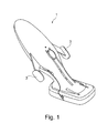
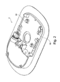
- Insertion device 1 shown in FIGS FIG. 2 The base unit 2 shown together form an insertion system with which, for example, sensors can be inserted into the body of a patient by means of insertion needles or catheters for the infusion of insulin or other active substances.
- the base unit 2 is glued with its underside on the body of a patient and then the insertion device 1 is coupled to the base unit 2.
- Insertion device 1 shown has two actuators 3, which are moved towards each other for insertion in a drive movement.
- This drive movement is from one in the FIGS. 3 to 6 shown drive mechanism in a stitch movement of an insertion needle holder and thus implemented an insertion needle.
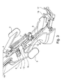
- the actuators 3 are provided with racks 4, which upon compression of the two actuators 3, a rotor 5 in rotation offset, which is converted via a connecting rod 6 in a linear stitch movement of an insertion needle holder 7 and an insertion needle 8 carried by him.
- the racks 4, the rotor 5 and the connecting rod 6 together form the drive mechanism of the insertion device. 1
- the insertion device 1 has a locking mechanism 10, which causes an inhibition of the drive mechanism in an active state, that blocks its movement, and is put into an inactive state by coupling the insertion device 1 to the base unit 2 , in which the lock is released.
- the locking mechanism 10 has a slider 11 which carries a locking element 12 which is in the in FIG. 3 shown active state engages in a recess 13 of the actuating elements 3 and thus blocks the drive mechanism.
- the slider 11 is pivotally connected via an arm 15 with a locking element 16 which is pushed when coupling the insertion device 1 to the base unit 2 in an engaged position in which it connects the insertion device 1 positively to the base unit 2.
- a displacement of the locking element 16 is prevented by a blocking element 17.
- the blocking element 17 When coupling the insertion device 1 to the base unit 2, the blocking element 17 is moved by the base unit 2 transversely to the direction of displacement of the locking element 16, raised in the illustrated embodiment, and released a leading into the engaged position displacement for the locking element 16. By a subsequent displacement movement, the locking element 16 engages with the base unit 2 in which it is pushed under designated engagement elements 18, in particular in FIG. 2 and 4 you can see.
- This sliding movement is indicated by an in FIG. 3 illustrated spring 19 causes, which is formed in the illustrated embodiment as a coil spring, preferably made of plastic, and presses on the slider 11.
- the spring 19 relaxes when the locking mechanism 11 from the in FIG. 3 shown active state in its in FIG. 4 illustrated inactive state passes. In this case, the spring 19 moves the slider 11 in the needle direction. This sliding movement is transmitted via the articulated arm 15 to the locking element 16, which thereby moves into its engaged position in the base unit 2.
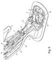
- FIG. 5 and 6 show a further embodiment, which differs from the embodiment described above substantially only in that a supported by the slider 11 blocking element 12 in the in FIG. 5 shown active state of the locking mechanism 10 engages in the gear formed as a rotor 5 of the drive mechanism and blocks it so. By displacement in the slider 11 in the stitching direction of the locking mechanism in the in FIG. 6 shown inactive state.
- a risk of injury during handling of the insertion device 1 is additionally reduced by the fact that a component of the locking mechanism 10 is in the active state of the locking mechanism in the needle direction in front of an insertion needle 8 held by the insertion needle holder 8.
- this acting as a protective element component is a sliding plate, which also forms the locking element 16.
- the locking member 16 In the transition of the locking mechanism 10 in its inactive state, the locking member 16 is displaced so that the insertion needle 8 can be moved through an opening provided in the bottom of the base unit 2 and thus inserted into the body of a patient.
- the slider 11 of the locking mechanism 10 is displaceable in the two embodiments in the stitching direction and provided with a linear guide.
- the linear guide is formed as a slot in the slider 11 through which a guide member 20 of the housing engages.
- the actuators 3 can latch at the end of a drive movement with a locking mechanism, not shown, so that after uncoupling an insertion device 1 of the base unit 2, that is, after an insertion, an unintentional Stitch movement that could lead to injury can be avoided.
- the drive mechanism causes following a stitch movement a return movement of the insertion needle holder 7.
- the coupling between the insertion device 1 and base unit 2 is solved by this return movement again.
- the slider 11 is coupled to the insertion needle holder 7 during the return movement and is withdrawn from it.
- the slider 11 may carry a slanted spring blade, which is bent during the stitch movement of the insertion needle holder, so that the insertion needle age 7 can slide over the slider 11 away.
- a leaflet can engage in the insertion needle holder 7, so that the slider 11 is withdrawn from the insertion needle holder 7 and consequently the locking element 16 is pulled out of its engagement position with the base unit 2 via the arm 15.
Abstract
Description
Die Erfindung betrifft ein Insertionssystem mit den im Oberbegriff des Anspruchs 1 angegebenen Merkmalen sowie eine entsprechende Insertionsvorrichtung.The invention relates to an insertion system with the features specified in the preamble of
Um Sensoren zur Messung von Analytkonzentrationen in vivo, beispielsweise der Glukosekonzentrationen, in Körpergewebe eines Patienten zu insertieren, beispielsweise in Unterhautfettgewebe, werden Insertionsvorrichtungen verwendet, die mit einem Antriebsmechanismus eine Stichbewegung einer Insertionsnadel bewirken. Hierfür gebräuchliche Insertionsnadeln sind als Hohlnadeln oder V-förmige Rinnen ausgebildet, in denen ein Sensor liegt. Der Sensor kann beispielsweise als ein Elektrodensystem für elektrochemische Messungen ausgebildet sein oder einen mikrofluidischen Katheter zum Ein- und Ausleiten einer Perfusionsflüssigkeit umfassen. Nach einem Einstich wird die Insertionsnadel aus dem Körpergewebe herausgezogen, wobei der Sensor in der erzeugten Stichwunde verbleibt.In order to insert sensors for measuring analyte concentrations in vivo, for example, the glucose concentrations, in body tissue of a patient, for example, in subcutaneous fatty tissue, insertion devices are used, which cause a stitching movement of an insertion needle with a drive mechanism. For this customary insertion needles are designed as hollow needles or V-shaped grooves in which a sensor is located. The sensor can be designed, for example, as an electrode system for electrochemical measurements or comprise a microfluidic catheter for introducing and removing a perfusion fluid. After a puncture, the insertion needle is pulled out of the body tissue, the sensor remains in the puncture wound produced.
Eine weitere Anwendung von Insertionsvorrichtungen ist beispielsweise die Applikation von Kathetern, insbesondere zur Infusion von Insulin oder anderen Wirkstoffen.Another application of insertion devices is, for example, the application of catheters, in particular for the infusion of insulin or other active ingredients.
Derartige Insertionsvorrichtungen bilden zusammen mit einer Basiseinheit, an die sie für eine Insertion angekoppelt werden können, ein Insertionssystem. Basiseinheiten werden üblicherweise auf den Körper eines Patienten aufgeklebt. Anschließend kann eine Insertionsvorrichtung an die Basiseinheit angekoppelt werden. Nach abgeschlossener Insertion kann die Insertionsvorrichtung von der Basiseinheit abgekoppelt werden, so dass die Basiseinheit beispielsweise als Träger oder Anschlusselement eines insertierten Sensors oder Katheters auf dem Körper des Patienten verbleibt.Such insertion devices form an insertion system together with a base unit to which they can be coupled for insertion. Base units are usually adhered to the body of a patient. Subsequently, an insertion device can be coupled to the base unit. After insertion has been completed, the insertion device can be uncoupled from the base unit, so that the base unit, for example, remains on the body of the patient as a support or connection element of an inserted sensor or catheter.
Insertionssysteme werden häufig von den Patienten selbst bedient, beispielsweise um Katheter zum Anschließen an eine Insulinpumpe oder Sensoren zur Messung der Glukosekonzentration zu Insertieren. Bei der Entwicklung von derartigen Insertionssystemen ist es deshalb ein ständiges Ziel, dass diese möglichst einfach und sicher bedient werden können.Insertion systems are often operated by the patients themselves, for example, to insert catheters for connection to an insulin pump or sensors for measuring the glucose concentration. In the development of such insertion systems, it is therefore a constant goal that they can be operated as simply and safely.
Diese Aufgabe wird durch ein Insertionssystem mit den im Anspruch 1 angegebenen Merkmalen sowie eine Insertionsvorrichtung für ein solches Insertionssystem gemäß Anspruch 2 gelöst. Vorteilhafte Weiterbildungen der Erfindung sind Gegenstand von Unteransprüchen.This object is achieved by an insertion system having the features specified in
Erfindungsgemäß ist vorgesehen, dass die Insertionsvorrichtung einen Sperrmechanismus aufweist, der in einem aktiven Zustand eine Sperrung des Antriebsmechanismus bewirkt und durch Ankoppeln der Insertionsvorrichtung an die Basiseinheit in einen inaktiven Zustand versetzt wird, in dem die Sperrung gelöst ist. Mit einem solchen Sperrmechanismus, der in seinem aktiven Zustand den Antriebsmechanismus blockiert, kann ein vorzeitiges Auslösen eines Stichs verhindert und so die Gefahr einer Verletzung bei der Handhabung der Insertionsvorrichtung reduziert werden.According to the invention it is provided that the insertion device has a locking mechanism which causes an inhibition of the drive mechanism in an active state and is put into an inactive state by coupling the insertion device to the base unit, in which the lock is released. With such a locking mechanism, which blocks the drive mechanism in its active state, can prevent premature triggering of a stitch and thus reduce the risk of injury in the handling of the insertion device.
Bei einer erfindungsgemäßen Insertionsvorrichtung entriegelt der Sperrmechanismus automatisch, wenn die Insertionsvorrichtung an die Basiseinheit angekoppelt wird. Erfindungsgemäß lässt sich deshalb erreichen, dass der Sperrmechanismus nur dann entriegelt ist, wenn die Insertionsvorrichtung an die Basiseinheit angekoppelt ist. Vorteilhaft lässt sich also erreichen, dass ein Benutzer den Sperrmechanismus nur durch Ankoppeln der Insertionsvorrichtung an die Basiseinheit entriegeln kann. Ein Stich lässt sich folglich vorteilhaft nur auslösen, wenn die Insertionsvorrichtung an die Basiseinheit angekoppelt ist, so dass die Gefahr einer Verletzung bei fehlerhafter Handhabung weitestgehend ausgeschlossen ist.In an insertion device according to the invention, the locking mechanism unlocks automatically when the insertion device is coupled to the base unit. According to the invention can therefore achieve that the locking mechanism only then unlocked when the insertion device is coupled to the base unit. Advantageously, it can thus be achieved that a user can unlock the locking mechanism only by coupling the insertion device to the base unit. Consequently, a puncture can be advantageously triggered only when the insertion device is coupled to the base unit, so that the risk of injury in case of incorrect handling is largely excluded.
Neben einer erhöhten Sicherheit vor Verletzungen hat ein erfindungsgemäßer Sperrmechanismus zudem den Vorteil, dass sich die Bedienbarkeit der Insertionsvorrichtung wesentlich vereinfachen lässt. Während bei bekannten Insertionsvorrichtungen nämlich in der Regel mehr oder weniger aufwendige und komplizierte Auslöse- oder Betätigungsmechanismen verwendet werden, um ein unbeabsichtigtes Auslösen eines Stichs zu verhindern, beispielsweise indem mehrer Betätigungselemente vorgesehen sind, die in einer vorgegebene Reihenfolge oder Kombination betätigt werden müssen, kann bei einem erfindungsgemäßen Insertionssystem auf derartige Maßnahmen verzichtet werden. Da der Antriebsmechanismus nur nach Ankopplung der Insertionsvorrichtung an die Basiseinheit einen Stich bewirken kann, ist selbst bei Einsatz von beliebig einfachen Auslöse- oder Betätigungsmechanismen ein vorzeitiges Auslösen eines Stichs ausgeschlossen.In addition to increased security against injury, a locking mechanism according to the invention also has the advantage that the operability of the insertion device can be substantially simplified. While in known insertion devices namely more or less complex and complicated triggering or actuating mechanisms are used to prevent inadvertent triggering of a sting, for example by several actuators are provided, which must be operated in a predetermined order or combination, can at an insertion system according to the invention can be dispensed with such measures. Since the drive mechanism can cause a puncture only after coupling of the insertion device to the base unit, premature triggering of a puncture is ruled out even when using any simple triggering or actuating mechanisms.
Ein erfindungsgemäßer Sicherungsmechanismus kann beispielsweise durch Magnetkraft aus seinem aktiven Zustand in seinen inaktiven Zustand versetzt werden. Hierfür erforderliche Magnete können an der Basiseinheit und/oder der Insertionsvorrichtung angebracht sein. Möglich ist es auch, den Sicherungsmechanismus elektrisch zu deaktivieren, indem beim Ankoppeln der Insertionsvorrichtung an die Basiseinheit ein elektrischer Kontakt geschlossen wird. Bevorzugt funktioniert der Sicherungsmechanismus aber rein mechanisch, beispielsweise, indem an der Basiseinheit ein Indexstift vorgesehen ist, der beim Ankoppeln den Sicherungsmechanismus betätigt und dabei in den inaktiven Zustand versetzt.A securing mechanism according to the invention can be set from its active state to its inactive state by magnetic force, for example. Magnets required for this purpose can be attached to the base unit and / or the insertion device. It is also possible to electrically deactivate the securing mechanism by closing an electrical contact when coupling the insertion device to the base unit. Preferably, however, the securing mechanism functions purely mechanically, for example, by providing an indexing pin on the base unit, which actuates the securing mechanism during coupling and thereby puts it in the inactive state.
Ein erfindungsgemäßer Sperrmechanismus kann beispielsweise mit einer Sperrklinke, einer Wippe oder einem ähnlichen Sperrelement arbeiten, das durch eine Dreh- oder Schwenkbewegung aus einem Sperrzustand in einen inaktiven Zustand versetzt wird. Bevorzugt weist der Sperrmechanismus jedoch einen Schieber auf, der bei einem Wechsel des Sperrmechanismus aus dem aktiven Zustand in den inaktiven Zustand verschoben wird. Ein solcher Schieber kann beispielsweise ein Sperrelement tragen, das den Antriebsmechanismus blockiert, insbesondere durch einen formschlüssigen Eingriff.A locking mechanism according to the invention may, for example, operate with a pawl, a rocker or a similar locking element, which is set in an inactive state by a turning or pivoting movement from a blocking state. Preferably, however, the locking mechanism has a slider which is at a Change the locking mechanism from the active state to the inactive state is moved. Such a slider may, for example, carry a locking element which blocks the drive mechanism, in particular by a positive engagement.
Möglich ist es auch, dass der bevorzugt bei einem erfindungsgemäßen Sperrmechanismus vorhandene Schieber selbst als Sperrelement durch formschlüssigen Eingriff in den Antriebsmechanismus oder in ein benutzerbetätigbares Betätigungselement eine Sperrung des Antriebsmechanismus bewirkt. An sich könnte ein solcher Schieber bei einem Wechsel des Sperrmechanismus aus dem aktiven Zustand in den inaktiven Zustand in einer beliebigen Richtung verschoben werden. Bevorzugt ist der Schieber aber in Stichrichtung verschiebbar, da dies einen kompakten Aufbau erleichtert.It is also possible that the slider preferably present in a locking mechanism according to the invention itself causes a blocking of the drive mechanism as a blocking element by positive engagement in the drive mechanism or in a user-operable actuator. In itself such a slide could be moved in a change of the locking mechanism from the active state to the inactive state in any direction. Preferably, however, the slider is displaceable in the stinging direction, since this facilitates a compact construction.
Eine vorteilhafte Weiterbildung der Erfindung sieht vor, dass der Schieber federbeaufschlagt ist. Als Feder kann dabei ein beliebiges Bauteil verwendet werden, das bei Verformung eine Rückstellkraft erzeugt. Beispielsweise können als Feder ein elastisch verformbarer Kunststoffblock, eine Wendel aus Kunststoff oder Metall und ein elastisch verformbares Band, beispielsweise ein Gummiband, verwendet werden. Durch Einsatz eines federbeaufschlagten Schiebers lässt sich erreichen, dass dieser durch Federkraft zu seiner Anfangs- oder Endposition hinbewegt wird. Die Gefahr, dass der Schieber längere Zeit in einem undefinierten Zwischenzustand zwischen Anfangs- und Endposition verbleibt, lässt sich folglich reduzieren. Bevorzugt entspannt sich die Feder bei einem Wechsel des Sperrmechanismus in den inaktiven Zustand, gibt also zumindest einen Teil der in ihr gespeicherten Energie frei. Diese Maßnahme hat den Vorteil, dass ein Benutzer für das Deaktivieren des Sperrmechanismus keine zusätzliche Kraft aufbringen muss. Zudem lässt sich auf diese Weise ein besonders einfacher Aufbau des Sperrmechanismus erreichen, da es genügt im aktiven Zustand des Sperrmechanismus eine Verschiebung des Schiebers mit einem beweglichen Element, beispielsweise einem Anschlag oder einer Sperre, zu blockieren. Beim Ankoppeln der Insertionsvorrichtung an eine Basiseinheit kann ein solches Element durch Kontakt mit einem passenden Bauteil der Basiseinheit bewegt und so eine Verschiebung des Schiebers ermöglicht werden.An advantageous development of the invention provides that the slide is spring loaded. As a spring, any component can be used, which generates a restoring force during deformation. For example, can be used as a spring, an elastically deformable plastic block, a coil made of plastic or metal and an elastically deformable band, such as a rubber band. By using a spring-loaded slider can be achieved that this is moved by spring force to its initial or final position. The risk that the slide remains in an undefined intermediate state between the start and end position for an extended period of time can consequently be reduced. Preferably, the spring relaxes in a change of the locking mechanism in the inactive state, so at least releases a part of the energy stored in it. This measure has the advantage that a user does not have to apply additional force for deactivating the locking mechanism. In addition, can be achieved in this way a particularly simple construction of the locking mechanism, since it is sufficient in the active state of the locking mechanism to block a displacement of the slider with a movable element, such as a stop or a lock. When coupling the insertion device to a base unit, such an element can be moved by contact with a matching component of the base unit and thus a displacement of the slider can be made possible.
Bevorzugt ist der Schieber mit einem Verriegelungselement gekoppelt, das beim Ankoppeln der Insertionsvorrichtung an die Basiseinheit in eine Eingriffsposition geschoben wird, in der es die Insertionsvorrichtung formschlüssig mit der Basiseinheit verbindet. Auf diese Weise lässt sich erreichen, dass der Sperrmechanismus erst dann in seinen inaktiven Zustand übergeht, wenn die Insertionsvorrichtung formschlüssig und damit zuverlässig mit der Basiseinheit verbunden ist.Preferably, the slider is coupled to a locking element which is pushed when coupling the insertion device to the base unit in an engaged position in which it connects the insertion device form-fitting manner with the base unit. In this way it can be achieved that the locking mechanism does not change to its inactive state until the insertion device is positively connected and thus reliably connected to the base unit.
Bevorzugt weist der Sperrmechanismus ein Schutzelement auf, das sich in dem aktiven Zustand des Sperrmechanismus in Stichrichtung vor einer von dem Insertionsnadelhalter gehaltenen Insertionsnadel befindet. Diese Maßnahme hat den Vorteil, dass die Insertionsnadel abgedeckt und folglich die Verletzungsgefahr beim Handhaben der Insertionsvorrichtung noch weiter reduziert ist. Ein solches Schutzelement kann beispielsweise mit dem erwähnten Schieber verbunden sein, insbesondere gelenkig verbunden sein, so dass es bei einem Übergang des Sperrmechanismus in den inaktiven Zustand beiseite geschoben und so der Weg für eine Stichbewegung der Insertionsnadel freigegeben wird. Das Schutzelement, das beispielsweise plattenförmig ausgebildet sein kann, kann vorteilhaft mit dem erwähnten Verriegelungselement verbunden sein, insbesondere auch einstückig mit dem Verriegelungselement ausgebildet sein, das beim Ankoppeln der Insertionsvorrichtung einen Formschluss mit der Basiseinheit bewirkt.Preferably, the locking mechanism on a protective element, which is in the active state of the locking mechanism in the direction of stitching in front of a held by the insertion needle holder insertion needle. This measure has the advantage that the insertion needle is covered and consequently the risk of injury when handling the insertion device is further reduced. Such a protective element may, for example, be connected to the slide mentioned, in particular articulated, so that it is pushed aside when the locking mechanism moves into the inactive state, thus clearing the way for a puncturing motion of the insertion needle. The protective element, which may be formed plate-shaped, for example, may advantageously be connected to the mentioned locking element, in particular also be formed integrally with the locking element, which causes a positive connection with the base unit when coupling the insertion device.
Der Antriebsmechanismus einer erfindungsgemäßen Insertionsvorrichtung kann einen Energiespeicher, beispielsweise eine Feder, enthalten, um die für eine Stichbewegung erforderliche Energie zu liefern. Möglich ist es aber auch, dass der Antriebsmechanismus einer erfindungsgemäßen Insertionsvorrichtung im Betrieb eine Antriebsbewegung eines Betätigungselements in eine Stichbewegung des Insertionsnadelhalters umsetzt. Bevorzugt ist dabei, dass der Antriebsmechanismus im Anschluss an eine Stichbewegung eine Rückführbewegung des Insertionsnadelhalters bewirkt und nach abgeschlossener Rückführbewegung blockiert wird. Diese Blockade kann ebenfalls durch den Sperrmechanismus oder durch einen davon unabhängigen Mechanismus bewirkt werden. Beispielsweise ist es möglich, dass ein Betätigungselement, dessen Antriebsbewegung von dem Antriebsmechanismus in eine Stichbewegung umgesetzt wird, am Ende seines Betätigungswegs einrastet.The drive mechanism of an insertion device according to the invention may contain an energy store, for example a spring, in order to supply the energy required for a stitch movement. But it is also possible that the drive mechanism of an insertion device according to the invention converts a drive movement of an actuating element in a stitch movement of the insertion needle holder. It is preferred that the drive mechanism causes a return movement of the insertion needle holder following a stitch movement and is blocked after completed return movement. This blockage can also be effected by the locking mechanism or by a mechanism independent of it. For example, it is possible that an actuating element whose drive movement is converted by the drive mechanism into a stitch movement, engages at the end of its actuation path.
Weitere Einzelheiten und Vorteile der Erfindung werden an Ausführungsbeispielen unter Bezugnahme auf die beigefügten Zeichnungen beschrieben. Gleiche und einander entsprechende Bauteile sind dabei mit übereinstimmenden Bezugszahlen gekennzeichnet. Es zeigen:
Figur 1- ein Ausführungsbeispiel einer erfindungsgemäßen Insertionsvorrichtung;
Figur 2- ein Ausführungsbeispiel einer dazugehörenden Basiseinheit;
Figur 3- einen Ausschnitt der in
Figur 1 - Figur 4
- eine Ansicht gemäß
Figur 3 Figur 5- einen Ausschnitt eines weiteren Ausführungsbeispiels einer Insertionsvorrichtung bei geöffnetem Gehäuse; und
Figur 6- eine Ansicht gemäß
Figur 5
- FIG. 1
- an embodiment of an insertion device according to the invention;
- FIG. 2
- an embodiment of an associated base unit;
- FIG. 3
- a section of in
FIG. 1 shown insertion device with the housing open; - FIG. 4
- a view according to
FIG. 3 with coupled base unit; - FIG. 5
- a section of another embodiment of an insertion device with the housing open; and
- FIG. 6
- a view according to
FIG. 5 with docked base unit.
Die in
Die in
Wie
Um einer Verletzungsgefahr durch eine vorzeitige Stichbewegung zu begegnen, hat die Insertionsvorrichtung 1 einen Sperrmechanismus 10, der in einem aktiven Zustand eine Sperrung des Antriebsmechanismus bewirkt, also dessen Bewegung blockiert, und durch Ankoppeln der Insertionsvorrichtung 1 an die Basiseinheit 2 in einen inaktiven Zustand versetzt wird, in dem die Sperrung gelöst ist.In order to counteract a risk of injury by premature stabbing, the
Bei dem in
Beim Ankoppeln der Insertionsvorrichtung 1 an die Basiseinheit 2 wird das Blockadeelement 17 durch die Basiseinheit 2 quer zur Verschieberichtung des Verriegelungselements 16 bewegt, bei dem dargestellten Ausführungsbeispiel angehoben, und so ein in die Eingriffsposition führender Verschiebeweg für das Verriegelungselement 16 freigegeben. Durch eine anschließende Verschiebebewegung tritt das Verriegelungselement 16 mit der Basiseinheit 2 in Eingriff, nämlich in dem es unter dafür vorgesehene Eingriffselemente 18 geschoben wird, die insbesondere in
Diese Verschiebebewegung wird durch eine in
Die
Bei beiden Ausführungsbeispielen wird eine Verletzungsgefahr bei Handhabung der Insertionsvorrichtung 1 zusätzlich dadurch reduziert, dass ein Bauteil des Sperrmechanismus 10 sich in dem aktiven Zustand des Sperrmechanismus in Stichrichtung vor einer von dem Insertionsnadelhalter 7 gehaltenen Insertionsnadel 8 befindet. Bei den dargestellten Ausführungsbeispielen ist dieses als Schutzelement wirkende Bauteil eine Schiebeplatte, die zugleich das Verriegelungselement 16 bildet. Beim Übergang des Sperrmechanismus 10 in seinen inaktiven Zustand wird das Verriegelungselement 16 so verschoben, dass die Insertionsnadel 8 durch eine im Boden der Basiseinheit 2 vorgesehene Öffnung hindurch bewegt und so in den Körper eines Patienten eingestochen werden kann.In both embodiments, a risk of injury during handling of the
Der Schieber 11 des Sperrmechanismus 10 ist bei den beiden Ausführungsbeispielen jeweils in Stichrichtung verschiebbar und mit einer Linearführung versehen. Bei den dargestellten Ausführungsbeispielen ist die Linearführung als ein Schlitz in dem Schieber 11 ausgebildet, durch den ein Führungselement 20 des Gehäuses hindurch greift.The
Die Betätigungselemente 3 können am Ende einer Antriebsbewegung mit einem nicht dargestellten Rastmechanismus verrasten, damit nach dem Abkoppeln einer Insertionsvorrichtung 1 von der Basiseinheit 2, also nach einer Insertion, eine unbeabsichtigte Stichbewegung, die zu einer Verletzung führen könnte, vermieden werden kann.The
Der Antriebsmechanismus bewirkt im Anschluss an eine Stichbewegung eine Rückführbewegung des Insertionsnadelhalters 7. Bevorzugt wird durch diese Rückführbewegung die Kopplung zwischen Insertionsvorrichtung 1 und Basiseinheit 2 wieder gelöst. Dies kann beispielsweise dadurch erreicht werden, dass der Schieber 11 bei der Rückführbewegung an den Insertionsnadelhalter 7 koppelt und von ihm zurückgezogen wird. Beispielsweise kann der Schieber 11 ein schräg stehendes Federblättchen tragen, das bei der Stichbewegung von dem Insertionsnadelhalter umgebogen wird, so dass der Insertionsnadelnalter 7 über den Schieber 11 hinweg gleiten kann. Bei der Rückführbewegung kann ein solches Federblättchen in den Insertionsnadelhalter 7 eingreifen, so dass der Schieber 11 von dem Insertionsnadelhalter 7 zurückgezogen wird und folglich über den Arm 15 auch das Verriegelungselement 16 aus seiner Eingriffsposition mit der Basiseinheit 2 gezogen wird.The drive mechanism causes following a stitch movement a return movement of the
- 11
- Insertionsvorrichtunginsertion
- 22
- Basiseinheitbase unit
- 33
- Betätigungselementactuator
- 44
- Zahnstangerack
- 55
- Rotorrotor
- 66
- Pleuelpleuel
- 77
- Insertionsnadelhalterinsertion needle
- 88th
- Insertionsnadelinsertion needle
- 99
- 1010
- Sperrmechanismuslocking mechanism
- 1111
- Schieberpusher
- 1212
- Sperrelementblocking element
- 1313
- Ausnehmungrecess
- 1414
- 1515
- Armpoor
- 1616
- Verriegelungselementlocking element
- 1717
- Blockadeelementblockade element
- 1818
- Eingriffselementengaging member
- 1919
- Federfeather
- 2020
- Führungselementguide element
Claims (15)
einer Basiseinheit (2) zum Aufsetzen auf den Körper eines Patienten und
einer an die Basiseinheit (2) ankoppelbaren Insertionsvorrichtung (1),
wobei die Insertionsvorrichtung (1) einen Insertionsnadelhalter (7) zum Halten einer Insertionsnadel (8) und einen Antriebsmechanismus (4, 5, 6) zum Bewegen des Insertionsnadelhalters (7) in einer Stichrichtung aufweist,
dadurch gekennzeichnet, dass die Insertionsvorrichtung (1) einen Sperrmechanismus (10) aufweist, der in einem aktiven Zustand eine Sperrung des Antriebsmechanismus (4, 5, 6) bewirkt und durch Ankoppeln der Insertionsvorrichtung (1) an die Basiseinheit (2) in einen inaktiven Zustand versetzt wird, in dem die Sperrung gelöst ist.Insertion system with
a base unit (2) for placement on the body of a patient and
an insertion device (1) which can be coupled to the base unit (2),
the insertion device (1) having an insertion needle holder (7) for holding an insertion needle (8) and a drive mechanism (4, 5, 6) for moving the insertion needle holder (7) in a stitching direction,
characterized in that the insertion device (1) comprises a locking mechanism (10) which in an active state causes a blockage of the drive mechanism (4, 5, 6) and by coupling the insertion device (1) to the base unit (2) in an inactive State is set, in which the lock is released.
gekennzeichnet durch einen Sperrmechanismus (10), der in einem aktiven Zustand eine Sperrung des Antriebsmechanismus (4, 5, 6) bewirkt und durch Ankoppeln der Insertionsvorrichtung (1) an eine Basiseinheit (2) in einen inaktiven Zustand versetzt wird, in dem die Sperrung gelöst ist.Insertion device for an insertion system according to claim 1, wherein the insertion device (1) has an insertion needle holder (7) for holding an insertion needle (8) and a drive mechanism (4, 5, 6) for moving the insertion needle holder (7) in a needle direction,
characterized by a locking mechanism (10) which, in an active state, causes locking of the drive mechanism (4, 5, 6) and is brought into an inactive state by coupling the insertion device (1) to a base unit (2), in which the blocking is solved.
Priority Applications (6)
| Application Number | Priority Date | Filing Date | Title |
|---|---|---|---|
| EP08022458A EP2201968A1 (en) | 2008-12-24 | 2008-12-24 | Insertion system and insertion device |
| EP09756439.7A EP2376143B1 (en) | 2008-12-24 | 2009-11-19 | Insertion system and insertion device |
| CN200980152316XA CN102264415B (en) | 2008-12-24 | 2009-11-19 | Insertion system and insertion device |
| PCT/EP2009/008226 WO2010072290A1 (en) | 2008-12-24 | 2009-11-19 | Insertion system and insertion device |
| US13/168,197 US8506585B2 (en) | 2008-12-24 | 2011-06-24 | Insertion system and insertion device |
| HK12105157.4A HK1164188A1 (en) | 2008-12-24 | 2012-05-25 | Insertion system and insertion device |
Applications Claiming Priority (1)
| Application Number | Priority Date | Filing Date | Title |
|---|---|---|---|
| EP08022458A EP2201968A1 (en) | 2008-12-24 | 2008-12-24 | Insertion system and insertion device |
Publications (1)
| Publication Number | Publication Date |
|---|---|
| EP2201968A1 true EP2201968A1 (en) | 2010-06-30 |
Family
ID=40524641
Family Applications (2)
| Application Number | Title | Priority Date | Filing Date |
|---|---|---|---|
| EP08022458A Withdrawn EP2201968A1 (en) | 2008-12-24 | 2008-12-24 | Insertion system and insertion device |
| EP09756439.7A Active EP2376143B1 (en) | 2008-12-24 | 2009-11-19 | Insertion system and insertion device |
Family Applications After (1)
| Application Number | Title | Priority Date | Filing Date |
|---|---|---|---|
| EP09756439.7A Active EP2376143B1 (en) | 2008-12-24 | 2009-11-19 | Insertion system and insertion device |
Country Status (5)
| Country | Link |
|---|---|
| US (1) | US8506585B2 (en) |
| EP (2) | EP2201968A1 (en) |
| CN (1) | CN102264415B (en) |
| HK (1) | HK1164188A1 (en) |
| WO (1) | WO2010072290A1 (en) |
Cited By (1)
| Publication number | Priority date | Publication date | Assignee | Title |
|---|---|---|---|---|
| WO2015078636A1 (en) * | 2013-11-28 | 2015-06-04 | 4A Engineering Gmbh | Insertion aid for inserting a catheter for diabetics |
Families Citing this family (55)
| Publication number | Priority date | Publication date | Assignee | Title |
|---|---|---|---|---|
| US7967795B1 (en) | 2010-01-19 | 2011-06-28 | Lamodel Ltd. | Cartridge interface assembly with driving plunger |
| US10420880B2 (en) | 2007-10-02 | 2019-09-24 | West Pharma. Services IL, Ltd. | Key for securing components of a drug delivery system during assembly and/or transport and methods of using same |
| US9345836B2 (en) | 2007-10-02 | 2016-05-24 | Medimop Medical Projects Ltd. | Disengagement resistant telescoping assembly and unidirectional method of assembly for such |
| US9656019B2 (en) | 2007-10-02 | 2017-05-23 | Medimop Medical Projects Ltd. | Apparatuses for securing components of a drug delivery system during transport and methods of using same |
| WO2009044401A2 (en) | 2007-10-02 | 2009-04-09 | Yossi Gross | External drug pump |
| US9393369B2 (en) | 2008-09-15 | 2016-07-19 | Medimop Medical Projects Ltd. | Stabilized pen injector |
| US8157769B2 (en) | 2009-09-15 | 2012-04-17 | Medimop Medical Projects Ltd. | Cartridge insertion assembly for drug delivery system |
| USD810278S1 (en) | 2009-09-15 | 2018-02-13 | Medimop Medical Projects Ltd. | Injector device |
| US10071196B2 (en) | 2012-05-15 | 2018-09-11 | West Pharma. Services IL, Ltd. | Method for selectively powering a battery-operated drug-delivery device and device therefor |
| US10071198B2 (en) | 2012-11-02 | 2018-09-11 | West Pharma. Servicees IL, Ltd. | Adhesive structure for medical device |
| US8348898B2 (en) * | 2010-01-19 | 2013-01-08 | Medimop Medical Projects Ltd. | Automatic needle for drug pump |
| EP2569031B1 (en) | 2010-05-10 | 2017-10-11 | Medimop Medical Projects Ltd. | Low volume accurate injector |
| USD702834S1 (en) | 2011-03-22 | 2014-04-15 | Medimop Medical Projects Ltd. | Cartridge for use in injection device |
| US9072827B2 (en) | 2012-03-26 | 2015-07-07 | Medimop Medical Projects Ltd. | Fail safe point protector for needle safety flap |
| IL221634A0 (en) | 2012-08-26 | 2012-12-31 | Medimop Medical Projects Ltd | Universal drug vial adapter |
| EP2898828B1 (en) * | 2012-09-24 | 2019-04-03 | Terumo Kabushiki Kaisha | Sensor insertion device |
| US9421323B2 (en) | 2013-01-03 | 2016-08-23 | Medimop Medical Projects Ltd. | Door and doorstop for portable one use drug delivery apparatus |
| US9011164B2 (en) | 2013-04-30 | 2015-04-21 | Medimop Medical Projects Ltd. | Clip contact for easy installation of printed circuit board PCB |
| JP3205560U (en) | 2013-08-07 | 2016-08-04 | メディモップ・メディカル・プロジェクツ・リミテッド | Liquid transfer device for use with a drip liquid container |
| CN106535960B (en) * | 2014-07-22 | 2019-11-01 | 豪夫迈·罗氏有限公司 | Insertion apparatus with safety lock |
| WO2016012482A1 (en) | 2014-07-22 | 2016-01-28 | Roche Diagnostics Gmbh | Insertion device with protection against reuse |
| CH709930A2 (en) | 2014-07-29 | 2016-01-29 | Tecpharma Licensing Ag | Insertion device for an infusion. |
| CN108601706B (en) | 2015-01-05 | 2019-06-25 | 麦迪麦珀医疗工程有限公司 | With for guaranteeing the vial adapter component of proper use of quick release vial adapter |
| US10293120B2 (en) | 2015-04-10 | 2019-05-21 | West Pharma. Services IL, Ltd. | Redundant injection device status indication |
| US10149943B2 (en) | 2015-05-29 | 2018-12-11 | West Pharma. Services IL, Ltd. | Linear rotation stabilizer for a telescoping syringe stopper driverdriving assembly |
| WO2016196934A1 (en) | 2015-06-04 | 2016-12-08 | Medimop Medical Projects Ltd. | Cartridge insertion for drug delivery device |
| EP3319576B1 (en) | 2015-07-16 | 2019-10-02 | West Pharma. Services IL, Ltd | Liquid drug transfer devices for secure telescopic snap fit on injection vials |
| US10576207B2 (en) | 2015-10-09 | 2020-03-03 | West Pharma. Services IL, Ltd. | Angled syringe patch injector |
| US9987432B2 (en) | 2015-09-22 | 2018-06-05 | West Pharma. Services IL, Ltd. | Rotation resistant friction adapter for plunger driver of drug delivery device |
| CN113648488B (en) | 2015-10-09 | 2024-03-29 | 西医药服务以色列分公司 | Curved fluid path attachment to prefilled fluid reservoir |
| EP3380058B1 (en) | 2015-11-25 | 2020-01-08 | West Pharma Services IL, Ltd. | Dual vial adapter assemblage including drug vial adapter with self-sealing access valve |
| CN111544704B (en) | 2016-01-21 | 2022-06-03 | 西医药服务以色列有限公司 | Force containment in autoinjectors |
| CN113041432B (en) | 2016-01-21 | 2023-04-07 | 西医药服务以色列有限公司 | Medicament delivery device comprising a visual indicator |
| WO2017127215A1 (en) | 2016-01-21 | 2017-07-27 | Medimop Medical Projects Ltd. | Needle insertion and retraction mechanism |
| US11389597B2 (en) | 2016-03-16 | 2022-07-19 | West Pharma. Services IL, Ltd. | Staged telescopic screw assembly having different visual indicators |
| IL245803A0 (en) | 2016-05-24 | 2016-08-31 | West Pharma Services Il Ltd | Dual vial adapter assemblages including vented drug vial adapter and vented liquid vial adapter |
| IL245800A0 (en) | 2016-05-24 | 2016-08-31 | West Pharma Services Il Ltd | Dual vial adapter assemblages including identical twin vial adapters |
| EP3463526A1 (en) | 2016-06-02 | 2019-04-10 | West Pharma. Services Il, Ltd. | Three position needle retraction |
| IL246073A0 (en) | 2016-06-06 | 2016-08-31 | West Pharma Services Il Ltd | Fluid transfer devices for use with drug pump cartridge having slidable driving plunger |
| EP3978047B1 (en) | 2016-08-01 | 2023-08-23 | West Pharma Services IL, Ltd | Partial door closure prevention spring |
| US11338090B2 (en) | 2016-08-01 | 2022-05-24 | West Pharma. Services IL, Ltd. | Anti-rotation cartridge pin |
| IL247376A0 (en) | 2016-08-21 | 2016-12-29 | Medimop Medical Projects Ltd | Syringe assembly |
| EP3327873A1 (en) | 2016-11-25 | 2018-05-30 | Roche Diabetes Care GmbH | Medical device plug |
| IL249408A0 (en) | 2016-12-06 | 2017-03-30 | Medimop Medical Projects Ltd | Liquid transfer device for use with infusion liquid container and pincers-like hand tool for use therewith for releasing intact drug vial therefrom |
| IL251458A0 (en) | 2017-03-29 | 2017-06-29 | Medimop Medical Projects Ltd | User actuated liquid drug transfer devices for use in ready-to-use (rtu) liquid drug transfer assemblages |
| CN110869072B (en) | 2017-05-30 | 2021-12-10 | 西部制药服务有限公司(以色列) | Modular drive mechanism for a wearable injector |
| IL254802A0 (en) | 2017-09-29 | 2017-12-31 | Medimop Medical Projects Ltd | Dual vial adapter assemblages with twin vented female vial adapters |
| CN114470420A (en) | 2017-12-22 | 2022-05-13 | 西氏医药包装(以色列)有限公司 | Syringe adapted for cartridges of different sizes |
| JP1630477S (en) | 2018-07-06 | 2019-05-07 | ||
| USD923812S1 (en) | 2019-01-16 | 2021-06-29 | West Pharma. Services IL, Ltd. | Medication mixing apparatus |
| JP1648075S (en) | 2019-01-17 | 2019-12-16 | ||
| US11918542B2 (en) | 2019-01-31 | 2024-03-05 | West Pharma. Services IL, Ltd. | Liquid transfer device |
| US11446434B2 (en) | 2019-02-22 | 2022-09-20 | Deka Products Limited Partnership | Infusion set and inserter assembly systems and methods |
| WO2020222220A1 (en) | 2019-04-30 | 2020-11-05 | West Pharma. Services IL, Ltd. | Liquid transfer device with dual lumen iv spike |
| USD956958S1 (en) | 2020-07-13 | 2022-07-05 | West Pharma. Services IL, Ltd. | Liquid transfer device |
Citations (4)
| Publication number | Priority date | Publication date | Assignee | Title |
|---|---|---|---|---|
| US20040158207A1 (en) * | 2001-04-06 | 2004-08-12 | Marcel Hunn | Infusion set |
| WO2006061354A1 (en) * | 2004-12-06 | 2006-06-15 | Novo Nordisk A/S | Ventilated skin mountable device |
| WO2008065646A1 (en) * | 2006-11-28 | 2008-06-05 | Medingo Ltd. | An insertion device and method for inserting a subcutaneously insertable element into a body |
| WO2008078318A2 (en) * | 2006-12-22 | 2008-07-03 | Medingo Ltd. | Systems and devices for sustained delivery of therapeutic fluid |
Family Cites Families (1)
| Publication number | Priority date | Publication date | Assignee | Title |
|---|---|---|---|---|
| IL157984A (en) * | 2003-09-17 | 2015-02-26 | Dali Medical Devices Ltd | Autoneedle |
-
2008
- 2008-12-24 EP EP08022458A patent/EP2201968A1/en not_active Withdrawn
-
2009
- 2009-11-19 EP EP09756439.7A patent/EP2376143B1/en active Active
- 2009-11-19 CN CN200980152316XA patent/CN102264415B/en active Active
- 2009-11-19 WO PCT/EP2009/008226 patent/WO2010072290A1/en active Application Filing
-
2011
- 2011-06-24 US US13/168,197 patent/US8506585B2/en active Active
-
2012
- 2012-05-25 HK HK12105157.4A patent/HK1164188A1/en not_active IP Right Cessation
Patent Citations (4)
| Publication number | Priority date | Publication date | Assignee | Title |
|---|---|---|---|---|
| US20040158207A1 (en) * | 2001-04-06 | 2004-08-12 | Marcel Hunn | Infusion set |
| WO2006061354A1 (en) * | 2004-12-06 | 2006-06-15 | Novo Nordisk A/S | Ventilated skin mountable device |
| WO2008065646A1 (en) * | 2006-11-28 | 2008-06-05 | Medingo Ltd. | An insertion device and method for inserting a subcutaneously insertable element into a body |
| WO2008078318A2 (en) * | 2006-12-22 | 2008-07-03 | Medingo Ltd. | Systems and devices for sustained delivery of therapeutic fluid |
Cited By (2)
| Publication number | Priority date | Publication date | Assignee | Title |
|---|---|---|---|---|
| WO2015078636A1 (en) * | 2013-11-28 | 2015-06-04 | 4A Engineering Gmbh | Insertion aid for inserting a catheter for diabetics |
| US10426924B2 (en) | 2013-11-28 | 2019-10-01 | Medizinische Universität Graz | Placement aid for placing a catheter for diabetics |
Also Published As
| Publication number | Publication date |
|---|---|
| HK1164188A1 (en) | 2012-09-21 |
| CN102264415B (en) | 2013-12-18 |
| WO2010072290A1 (en) | 2010-07-01 |
| EP2376143A1 (en) | 2011-10-19 |
| EP2376143B1 (en) | 2018-09-05 |
| US8506585B2 (en) | 2013-08-13 |
| US20120022344A1 (en) | 2012-01-26 |
| CN102264415A (en) | 2011-11-30 |
Similar Documents
| Publication | Publication Date | Title |
|---|---|---|
| EP2376143B1 (en) | Insertion system and insertion device | |
| EP2026865B1 (en) | Arrangement for introducing a liquid into the body of a patient | |
| DE2845643C2 (en) | Catheter connection head with at least one channel in a base body | |
| EP1256358B1 (en) | Infusion set for drug delivery | |
| EP1970084B1 (en) | Insertion device for an insertion head, in particular for an infusion set | |
| EP2174680B1 (en) | Insertion device | |
| WO2001062316A1 (en) | Microperfusion device | |
| EP1737393A1 (en) | Device for inserting deformable intraocular lenses | |
| EP1565221A1 (en) | Catheter head with closing seal element | |
| EP1699508A1 (en) | Insertion unit for puncture devices | |
| DE4200595A1 (en) | Assembly group for infusion set for insulin pump - involves steel needle inside plastics cannula with only limited axial movement and drawn back into cannula during infusion. | |
| DE10255133B3 (en) | Apparatus for inserting needle unit, especially infusion head, into tissue comprises casing, to which a swiveling arm is attached which has mounting for unit at one end and can be lowered by release button on casing | |
| EP0991444A1 (en) | Cannular arrangement | |
| EP2575629A1 (en) | Joint biopsy needle for taking tissue samples | |
| EP3074082A1 (en) | Insertion aid for inserting a catheter for diabetics | |
| DE202007000578U1 (en) | Injection device for operating with a nozzle has a cap with corresponding threads, a casing, an outlet opening, a sleeve and a central hub | |
| EP0029864B1 (en) | Catheter connection head with at least one duct in the main body | |
| DE102018101275A1 (en) | Injector for transcutaneously introducing a sensor into a patient | |
| WO2014029521A1 (en) | Lancing device for obtaining samples of body fluid | |
| EP3539589B1 (en) | Safety device with needle dislocation detection and shut-off mechanism for an emergency stop of extracorporeal blood transport system | |
| EP1675634B1 (en) | Cannula holder | |
| EP1042986B1 (en) | Biopsy needle, needle holder and biopsy system | |
| DE102018208085A1 (en) | Implantation tool for subcutaneous implantation of a medical implant | |
| DE202023107089U1 (en) | Device for subcutaneous administration of a medication | |
| DE102017105481A1 (en) | injector |
Legal Events
| Date | Code | Title | Description |
|---|---|---|---|
| PUAI | Public reference made under article 153(3) epc to a published international application that has entered the european phase |
Free format text: ORIGINAL CODE: 0009012 |
|
| AK | Designated contracting states |
Kind code of ref document: A1 Designated state(s): AT BE BG CH CY CZ DE DK EE ES FI FR GB GR HR HU IE IS IT LI LT LU LV MC MT NL NO PL PT RO SE SI SK TR |
|
| AX | Request for extension of the european patent |
Extension state: AL BA MK RS |
|
| AKY | No designation fees paid | ||
| STAA | Information on the status of an ep patent application or granted ep patent |
Free format text: STATUS: THE APPLICATION IS DEEMED TO BE WITHDRAWN |
|
| 18D | Application deemed to be withdrawn |
Effective date: 20101231 |