EP2202484A1 - Microelectromechanical gyroscope with enhanced rejection of acceleration noise - Google Patents
Microelectromechanical gyroscope with enhanced rejection of acceleration noise Download PDFInfo
- Publication number
- EP2202484A1 EP2202484A1 EP09179819A EP09179819A EP2202484A1 EP 2202484 A1 EP2202484 A1 EP 2202484A1 EP 09179819 A EP09179819 A EP 09179819A EP 09179819 A EP09179819 A EP 09179819A EP 2202484 A1 EP2202484 A1 EP 2202484A1
- Authority
- EP
- European Patent Office
- Prior art keywords
- sensing
- mass
- driving
- movement
- structure according
- Prior art date
- Legal status (The legal status is an assumption and is not a legal conclusion. Google has not performed a legal analysis and makes no representation as to the accuracy of the status listed.)
- Withdrawn
Links
Images


Classifications
-
- B—PERFORMING OPERATIONS; TRANSPORTING
- B81—MICROSTRUCTURAL TECHNOLOGY
- B81B—MICROSTRUCTURAL DEVICES OR SYSTEMS, e.g. MICROMECHANICAL DEVICES
- B81B3/00—Devices comprising flexible or deformable elements, e.g. comprising elastic tongues or membranes
- B81B3/0018—Structures acting upon the moving or flexible element for transforming energy into mechanical movement or vice versa, i.e. actuators, sensors, generators
-
- G—PHYSICS
- G01—MEASURING; TESTING
- G01C—MEASURING DISTANCES, LEVELS OR BEARINGS; SURVEYING; NAVIGATION; GYROSCOPIC INSTRUMENTS; PHOTOGRAMMETRY OR VIDEOGRAMMETRY
- G01C19/00—Gyroscopes; Turn-sensitive devices using vibrating masses; Turn-sensitive devices without moving masses; Measuring angular rate using gyroscopic effects
- G01C19/56—Turn-sensitive devices using vibrating masses, e.g. vibratory angular rate sensors based on Coriolis forces
- G01C19/5705—Turn-sensitive devices using vibrating masses, e.g. vibratory angular rate sensors based on Coriolis forces using masses driven in reciprocating rotary motion about an axis
- G01C19/5712—Turn-sensitive devices using vibrating masses, e.g. vibratory angular rate sensors based on Coriolis forces using masses driven in reciprocating rotary motion about an axis the devices involving a micromechanical structure
-
- Y—GENERAL TAGGING OF NEW TECHNOLOGICAL DEVELOPMENTS; GENERAL TAGGING OF CROSS-SECTIONAL TECHNOLOGIES SPANNING OVER SEVERAL SECTIONS OF THE IPC; TECHNICAL SUBJECTS COVERED BY FORMER USPC CROSS-REFERENCE ART COLLECTIONS [XRACs] AND DIGESTS
- Y10—TECHNICAL SUBJECTS COVERED BY FORMER USPC
- Y10T—TECHNICAL SUBJECTS COVERED BY FORMER US CLASSIFICATION
- Y10T29/00—Metal working
- Y10T29/49—Method of mechanical manufacture
- Y10T29/49826—Assembling or joining
Definitions
- the present invention relates to a microelectromechanical structure, in particular a gyroscope sensitive to yaw angular accelerations, having enhanced mechanical characteristics, in particular in the rejection of acceleration noise.
- micromachining techniques enable manufacturing of microelectromechanical structures or systems (MEMS) within layers of semiconductor material, which have been deposited (for example, a layer of polycrystalline silicon) or grown (for example, an epitaxial layer) on sacrificial layers, which are removed by chemical etching.
- MEMS microelectromechanical structures or systems
- Inertial sensors, accelerometers, and gyroscopes built using this technology are having a growing success, for example, in the automotive field, in inertial navigation, or in the sector of portable devices.
- gyroscopes operate on the basis of the theorem of relative accelerations, exploiting the Coriolis acceleration.
- the mobile mass When an angular velocity is applied to a mobile mass that moves with a linear velocity, the mobile mass "feels" an apparent force, referred to as the "Coriolis force", which determines a displacement thereof in a direction perpendicular to a direction of the linear velocity and to an axis about which the angular velocity is applied.
- the mobile mass is supported via springs that enable its displacement in the direction of the apparent force.
- the displacement is proportional to the apparent force so that, from the displacement of the mobile mass, it is possible to detect the Coriolis force and the value of the angular velocity that has generated it.
- the displacement of the mobile mass can, for example, be detected capacitively, by determining, in resonance conditions, capacitance variations caused by movement of mobile electrodes, which are fixed with respect to the mobile mass and are comb-fingered with fixed electrodes.
- European patent application EP-A-1 832 841 and US patent applications US2009/0064780 and US2009/0100930 filed by the present applicant, disclose a microelectromechanical integrated sensor with rotary driving movement and sensitive to yaw angular velocities.
- the microelectromechanical sensor comprises a single driving mass, anchored to a substrate and actuated with rotary motion. Through openings are provided within the driving mass, and corresponding sensing masses are set in the through openings; the sensing masses are enclosed within the overall dimensions of the driving mass, are suspended with respect to the substrate, and are connected to the driving mass via flexible elements.
- Each sensing mass is fixed with respect to the driving mass during the rotary motion, and has a further degree of freedom of movement as a function of an external stress, in particular a Coriolis force, acting on the sensor.
- the flexible elements thanks to their particular construction, enable the sensing masses to perform a linear movement of detection in a radial direction belonging to the plane of the sensor, in response to a Coriolis acceleration.
- microelectromechanical structure in addition to being compact (in so far as it envisages a single driving mass enclosing in its overall dimensions a number of sensing masses), enables, with minor structural modifications, a uniaxial gyroscope, a biaxial gyroscope, or a triaxial gyroscope (and/or possibly an accelerometer, according to the electrical connections implemented) to be obtained, at the same time ensuring an excellent uncoupling of the driving dynamics from the detection dynamics.
- Figure 1 shows an exemplary embodiment of a uniaxial microelectromechanical gyroscope, designated by 1, provided according to the teachings contained in the aforesaid patent applications.
- the gyroscope 1 is provided in a die 2, comprising a substrate 2a made of semiconductor material (for example, silicon), and a frame 2b; the frame 2b defines inside it an open region 2c, which overlies the substrate 2a and is designed to house detection structure of the gyroscope 1 (as described in detail hereinafter).
- the open region 2c has a generally square or rectangular configuration in a horizontal plane (in what follows, plane of the sensor xy), defined by a first horizontal axis x and by a second horizontal axis y, which are fixed with respect to the die 2; the frame 2b has sides substantially parallel to the horizontal axes x, y.
- Die pads 2d are arranged along one side of the frame 2b, aligned, for example, along the first horizontal axis x. In a way not illustrated, the die pads 2d enable the detection structure of the gyroscope 1 to be electrically contacted from the outside.
- the gyroscope 1 comprises a driving structure, housed within the open region 2c and formed by a driving mass 3 and by a driving assembly 4.
- the driving mass 3 has, for example, a generally circular geometry with radial symmetry, with a substantially planar configuration with main extension in the plane of the sensor xy, and negligible dimension, with respect to the main extension, in a direction parallel to a vertical axis z, forming with the first and second horizontal axes x, y a set of three orthogonal axes, fixed with respect to the die 2.
- the driving mass 3 defines at the center an empty space 6, the center O of which coincides with the centroid and the center of symmetry of the entire structure.
- the driving mass 3 is anchored to the substrate 2a by means of a first anchorage 7a set at the center O, to which it is connected through first elastic anchorage elements 8a.
- the driving mass 3 is possibly anchored to the substrate 2a by means of further anchorages (not illustrated), set outside the same driving mass 3, to which it is connected by means of further elastic anchorage elements (not illustrated), for example, of the folded type.
- the first and further elastic anchorage elements enable a rotary movement of the driving mass 3 about an axis of actuation passing through the center O, parallel to the vertical axis z and perpendicular to the plane of the sensor xy, with a driving angular velocity ⁇ a .
- the driving mass 3 has a pair of through openings 9a, 9b, aligned in a radial direction, for example, along the second horizontal axis y, and set on opposite sides with respect to the empty space 6; the through openings 9a, 9b have in plan view a substantially rectangular shape, with main extension in a direction transverse to the radial direction.
- the driving assembly 4 comprises a plurality of driven arms 10, extending externally from the driving mass 3 in a radial direction and arranged at equal angular distances apart, and a plurality of first and second driving arms 12a, 12b, extending parallel to, and on opposite sides of, respective driven arms 10.
- Each driven arm 10 carries a plurality of first electrodes 13, extending perpendicular to, and on both sides of, the same driven arm 10.
- each of the first and second driving arms 12a, 12b carries respective second electrodes 14a, 14b, extending towards the respective driven arm 10, and comb-fingered with the corresponding first electrodes 13.
- the first driving arms 12a are set all one side of the respective driven arms 10, and are all biased at a first voltage; likewise, the second driving arms 12b are all set on the opposite side of the respective driven arms 10, and are all biased at a second voltage.
- a driving circuit (not illustrated) is connected to the second electrodes 14a, 14b to apply the first and second voltages and determine, by means of mutual and alternating attraction of the electrodes, an oscillatory rotary motion of the driving mass 3 about the driving axis, at a given oscillation frequency and driving angular velocity ⁇ a .
- the gyroscope 1 further comprises a pair of acceleration sensors with axis parallel to the aforesaid radial direction, and in particular a pair of sensing masses 15a, 15b housed within the through openings 9a, 9b; the sensing masses 15a, 15b have, for example, a generally rectangular shape with sides parallel to corresponding sides of the through openings 9a, 9b, are suspended with respect to the substrate 2a, and are connected to the driving mass 3 via elastic supporting elements 18.
- the elastic supporting elements 18 depart, for example, from the opposite major sides of each sensing mass in a radial direction.
- the elastic supporting elements 18 are rigid with respect to the motion of actuation of the driving mass 3 (in such a way that the sensing masses 15a, 15b will follow the driving mass 3 in the rotary movement), and also enable a linear movement of the respective sensing masses in the aforesaid radial direction.
- mobile electrodes 20 are coupled to the second sensing masses 15a, 15b, extending, for example, from respective minor sides, in a direction orthogonal to the radial direction; the mobile electrodes 20 form sensing capacitors with plane and parallel plates with respective first and second fixed electrodes 22a, 22b, anchored to the driving mass 3.
- each mobile electrode 20 forms a first sensing capacitor C 1 with a respective first fixed electrode 22a (for example, the radially more internal one with respect to the center O), and a second sensing capacitor C 2 with a respective second fixed electrode 22b (for example, the radially more external one with respect to the center O).
- the gyroscope 1 is able to detect an angular velocity ⁇ z (of yaw), acting about the vertical axis z.
- this angular velocity ⁇ z to be detected generates a Coriolis force F C on the sensing masses 15a, 15b oriented in a radial direction (hence directed as a centripetal force acting on the same masses), causing displacement of the sensing masses and a capacitive variation of the corresponding sensing capacitors C 1 , C 2 .
- the value of the capacitive variation is proportional to the angular velocity ⁇ z , which can thus be determined in a per-se known manner via a reading circuit, operating according to a differential scheme.
- the sensing masses 15a, 15b move in phase opposition in the radial direction (in other words, they displace in opposite senses, or orientations, with respect to the radial direction) so that the differential reading electronics generates an amplified electrical output quantity.
- external accelerations acting on the structure in the radial direction for example, accelerations due to environmental noise
- the external accelerations are ideally rejected automatically due to the differential reading.
- the useful Coriolis signal tends to unbalance the sensing masses 15a, 15b in opposite radial directions
- external accelerations determine variations with the same sign (or sense).
- the rotary driving motion also generates a centrifugal acceleration, which acts upon the sensing masses 15a, 15b, substantially in a way similar to the aforesaid Coriolis acceleration (i.e., causing a displacement thereof in opposite directions).
- the centrifugal acceleration causes a contribution at output having a frequency that is twice that of the Coriolis acceleration, and can consequently be appropriately filtered by the reading electronics.
- the gyroscope described in the aforesaid patent applications represents a considerable improvement as compared to other structures of a known type, it is not altogether optimized from the standpoint of the electrical characteristics and noise immunity.
- it is not perfectly immune to external accelerations (for example, noise accelerations), and also to the effects of the centrifugal acceleration acting on the structure on account of the rotary driving motion.
- the aim of the present invention is consequently to provide a further improvement to the microelectromechanical gyroscope structure, in particular as regards sensitivity to external acceleration noise and to centrifugal acceleration.
- a microelectromechanical structure is consequently provided according to the present invention, as defined in claim 1.
- the resonance frequencies of the two sensing masses 15a, 15b may, however, not be perfectly coincident (for example, they may differ from one another by 10-20 Hz), and this causes, for high factors of merit Q, a poor rejection to the external acceleration noise.
- external accelerations having a frequency close to the resonance frequencies of the sensing masses 15a, 15b can generate responses even considerably different in the two sensing masses, thus generating a non-zero output from the corresponding reading electronics (even though the differential scheme adopted is ideally able to reject these noises).
- the resonance frequency of the sensing masses has typical values in the region of 4-5 kHz, it is evident that also environmental noise with audio frequency can generate, for the reasons set forth above, even considerable output noises.
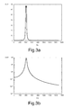
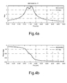
- Figures 3a and 3b show the results of numerical processing in which a process spread was simulated by applying a difference of 1% in the rigidity of the elastic supporting elements 18 associated to the sensing masses 15a, 15b, and a random displacement noise of the anchorage 7a (and of the possible further anchorages) of the driving mass was applied to simulate an external acceleration excitation.
- Figures 3a and 3b show, respectively, in linear and logarithmic scale, the output OUT of the reading electronics of the gyroscope 1 (and thus the result of the operations of amplification and demodulation of the signals at output from the sensing capacitors), whilst Figures 4a and 4b show, respectively, the magnitude (Mag) and the phase of the mechanical transfer function of the sensing masses 15a, 15b.
- These graphs highlight the presence of two distinct frequency peaks set at approximately 20 Hz apart, due to the different resonance frequencies of the two sensing masses 15a, 15b, and also the presence of a non-zero output from the reading electronics in the presence of noise acceleration (which could have values that can even be comparable with the values assumed during detection of angular accelerations).
- one embodiment of the present invention envisages mechanical coupling (in particular via appropriate elastic elements) of the two sensing masses so as to couple their detection vibration modes.
- the microelectromechanical gyroscope here designated by 30, differs from the gyroscope 1 of Figure 1 substantially in that it comprises elastic coupling elements 32a, 32b designed to couple the sensing masses 15a, 15b elastically to one another.
- a single through opening is present, here designated by 34, also coinciding with the empty space, here designated by 6', defined at the center of the driving mass 3 (here having the shape of a circular frame).
- the sensing masses 15a, 15b Located within the through opening 34 are both of the sensing masses 15a, 15b, and the various elastic elements designed to ensure coupling and mechanical support thereof via connection to the driving mass 3.
- a respective elastic coupling element 32a, 32b is associated to each sensing mass 15a, 15b; the elastic coupling element 32a, 32b departs, for example, from a major side of the respective sensing mass on an opposite side with respect to the elastic supporting elements 18 towards the center O (here just one elastic supporting element 18 is present for each sensing mass).
- the elastic coupling elements 32a, 32b are connected together via a connection body 35, set in a central position, for example, at the center O.
- the connection body 35 is configured so as to have substantially negligible weight and dimensions, in particular if compared with those of the same sensing masses and of the elastic elements.
- connection body 35 in addition to being connected to the aforesaid sensing masses 15a, 15b, is connected to the driving mass 3 via further elastic supporting elements 36.
- the further elastic supporting elements 36 for example, constituted by springs of the folded type, extend, for example, in a direction transverse to the radial direction of alignment of the sensing masses 15a, 15b (coinciding with the direction of extension of the elastic coupling elements 32a, 32b), at the center O.
- the further elastic supporting elements 36 operate to further constrain the sensing structure to the driving mass 3, in order to increase the rigidity of the sensing masses 15a, 15d with respect to translation along the vertical axis z.
- the elastic anchorage elements of the driving mass 3 are moreover arranged in a different way within the empty space 6'.
- four anchorages 7a' are provided, extending in pairs on either side of the further elastic supporting elements 36, to which the driving mass 3 is connected by means of respective elastic anchorage elements 8a', extending radially, in a way converging towards the center O.
- the elastic coupling elements 32a, 32b have, in use, the function of coupling the movements of vibration of the sensing masses 15a, 15b, giving rise to two different separate vibration modes of the resulting mechanical sensing structure.
- a first vibration mode, in phase, and a second vibration mode, in phase opposition are generated, having resonance frequencies that are clearly separate from one another.
- the two sensing masses 15a, 15b vibrate at the same frequency.
- the reading electronics here appropriately modified
- noise rejection is principally associated to a differential type reading, where the in-phase vibration mode does not generate a significant capacitive variation for the reading electronics.
- Figures 7a and 7b show the results of a numerical processing similar to the one previously described for the structure of a known type of Figure 1 , directly comparing the values obtained with the gyroscope 30 of Figure 5 (represented with a solid line) and the values obtained with said structure of a known type (represented with a dashed line).
- the aforesaid coupling enables a reduction in the output response of the gyroscope 30 to an external linear acceleration (for example, a noise acceleration) by approximately one hundred times as compared to a traditional solution.
- the mechanical system has a single peak, linked to the vibration mode in phase opposition, unlike solutions of a known type, which are characterized by a double peak in frequency.
- the described embodiment enables a considerable improvement of the rejection of the linear-acceleration noises in the plane xy of the sensor.
- the frequencies of the two modes of vibration remain substantially unaltered in the presence of process spread, and moreover the differential type reading enables convenient elimination of the undesirable contribution of the in-phase vibration mode.
- the aforesaid two different vibration modes derive from the different displacement modalities of the sensing masses 15a, 15b, during the movement in phase or in phase opposition.
- the displacement of the sensing masses 15a, 15b originates from the deformation both of the elastic coupling elements 32a, 32b and of the elastic supporting elements 18, so that the connection body 35 remains substantially still in a central position.
- the elastic coupling elements 32a, 32b undergo a smaller deformation as compared to the movement in phase opposition, the elastic supporting elements 36 (which in the movement in phase opposition were substantially stationary) are also deformed, and the connection body 35 displaces in the radial direction.
- the gyroscope 30 albeit advantageously enabling rejection of noise linear accelerations, is not altogether free from problems due to the presence of the centrifugal acceleration.
- the rotation of the driving mass 3 generates in fact a centrifugal acceleration acting on the sensing masses 15a, 15b in opposite directions with respect to the radial direction of detection, and hence generates a vibration thereof in phase opposition (in a way similar to the effects of the Coriolis force linked to the yaw angular acceleration that is to be detected).
- the centrifugal acceleration causes a contribution of vibration at a frequency that is twice that of the acceleration to be detected so that ideally it is possible to filter its contribution.
- the centrifugal acceleration notwithstanding the presence of an adequate filtering stage, can cause a saturation of the amplification stages in the reading electronics, and thus cause in any case errors in the detection of angular accelerations.
- a further embodiment of the present invention envisages automatic compensation, via an appropriate geometrical configuration of the sensing structure, of the effects of the centrifugal acceleration (i.e., providing an intrinsic mechanical compensation, as an alternative, or in addition, to a compensation made at the reading electronics level).
- a second embodiment of the gyroscope differs from the one described previously substantially for a different conformation of the mobile and fixed electrodes, here designated by 20' and, respectively, 22a', 22b', and, in the case illustrated, of the sensing masses, here designated by 15a', 15b'.
- this second embodiment envisages a suitable shaping of the mobile electrodes 20' and at least one between the respective first or second fixed electrode 22a', 22b', in such a way as to generate, during the rotary driving motion, a capacitive variation of the sensing capacitors able to compensate for a capacitive variation thereof due to the presence of the centrifugal acceleration.
- the sensing masses 15a', 15b' have in this case a substantially trapezoidal conformation with a window 40 defined inside; mobile electrodes 20' and the corresponding fixed electrodes 22a' (radially more internal) and 22b' (radially more external) are arranged within the window 40.
- the window 40 has, in the plane of the sensor xy, the shape of an annulus sector, and the mobile electrodes 20' and fixed electrodes 22a', 22b' are substantially arc-shaped.
- the mobile electrodes 20' extend inside the window 40, starting from oblique sides of the respective sensing mass 15a', 15b'.
- the first and second fixed electrodes 22a', 22b' associated to each mobile electrode 20' are set facing it on opposite sides, and are anchored to the substrate 2a via respective anchorages 42 (see Figure 10 ), which are also arranged within the window 40.
- two sets of mobile electrodes 20' and corresponding first and second fixed electrodes 22a', 22b' are present, each set in a respective half into which the aforesaid window 40 is divided by the radial detection direction.
- each mobile electrode 20' has a first lateral surface (in particular the surface facing the respective first fixed electrode 22a', or, equivalently, the lateral surface radially more internal with respect to the center O) that is shaped according to a suitable pattern, and a second lateral surface (in particular the surface facing the respective second fixed electrode 22b', or, equivalently, the lateral surface radially more external with respect to the center O) that is not shaped.
- the second lateral surface that is not shaped corresponds to an arc of circumference, whilst the first lateral surface that is shaped has a undulate, substantially sinusoidal, profile (as highlighted by the top plan view in the aforesaid Figures 10, 11a and 11b ).
- the first fixed electrode 22a' (radially more internal) has both of the lateral surfaces shaped, in particular having one and the same sinusoidal profile, substantially corresponding to the sinusoidal profile of the first lateral surface of the mobile electrode 20'.
- each mobile mass 15a', 15b' causes (as shown by the arrows) an undesired approach (in so far as it is not associated with the movement of detection of an angular acceleration) of each mobile electrode 20' towards the corresponding second fixed electrode 22b', and a corresponding displacement of the same mobile electrode 20' away from the corresponding first fixed electrode 22a', with a consequent decrease of capacitance of the first sensing capacitor C 1 , and an increase of capacitance of the second sensing capacitor C 2 (the increase being greater, in a known way, than the aforesaid decrease, given the non-linearity of the relation between capacitance and distance between the electrodes).
- the movement of rotation of the driving mass 3 also causes a circumferential displacement of the mobile electrode 20' with respect to the fixed electrodes 22a', 22b' (as shown by the arrows).
- this circumferential displacement causes a total capacitive variation of the first sensing capacitor C 1 (in particular a capacitive increase thereof due to a net approach between the plates) such as to equal and compensate for the variations of the second sensing capacitor C 2 due to the contribution of the centrifugal acceleration.
- the frequency contribution of the capacitive variation due to the shaping of the electrodes substantially corresponds to the frequency contribution due to the centrifugal acceleration (which, as indicated previously, has a frequency that is twice the detection frequency) so as to enable an effective compensation for the resulting capacitive variations.
- the aforesaid shaping it is possible to generate a capacitive difference between the sensing capacitors (a difference that is then processed by the reading electronics), which remains substantially constant in the absence of a Coriolis acceleration and thus of an angular acceleration to be detected.
- the value of capacitance of the second sensing capacitor C 2 is not affected by the circumferential displacement of the mobile electrode 20' due to the rotary driving motion, it is easy, via an appropriate mathematical model and appropriate computing algorithms, to determine the shaping parameters (in particular the parameters of the sinusoidal profile, in terms of amplitude and/or period) that allows to obtain a minimization of the capacitive difference ⁇ C between the sensing capacitors C 1 , C 2 due to the centrifugal acceleration.
- the shaping parameters in particular the parameters of the sinusoidal profile, in terms of amplitude and/or period
- an algorithm (of a known type, here not described in detail herein) of numeric integration of the capacitive variations over the entire surface of the electrodes may be used for this purpose, to determine the parameters of the geometrical shape of the electrodes such as to minimize the capacitive difference ⁇ C.
- the capacitive variation associated to a mobile electrode 20' during the driving motion on account of the sole centrifugal acceleration is represented with a solid line
- the capacitive variation associated to the same mobile electrode 20' caused by the sole shaping of the electrodes previously described is represented with a dashed line.
- the aforesaid capacitive variations are substantially equivalent.
- the compensation error on the resulting capacitive variation is, thanks to this intrinsic mechanical compensation, substantially zero or in any case negligible.
- this intrinsic compensation enables reduction of the noise effect of the centrifugal acceleration by a factor equal to 100.
- a further embodiment of the present invention envisages provision of a biaxial or triaxial gyroscope by adding to the previously described detection structure for sensing yaw angular accelerations, a detection structure for sensing pitch and/or roll angular accelerations, substantially as described in the aforesaid patent applications filed in the name of the present applicant.
- the gyroscope 30 (illustrated schematically) in this case comprises a first pair and a second pair of further sensing masses 46a-46b and 46c-46d, housed within respective through openings in the driving mass 3 and connected thereto via respective elastic elements 47.
- the further sensing masses 46a, 46b of the first pair are aligned in a first diametric direction x 1 , inclined with respect to the first horizontal axis x of the die 2 by an angle of inclination ⁇ (considered in a counterclockwise direction), the value of which is comprised between 40° and 50° and preferably is 45°.
- the further sensing masses 46c, 46d of the second pair are aligned in a second diametric direction x 2 , substantially orthogonal to the first diametric direction x 1 , and inclined with respect to the first horizontal axis x by the same angle of inclination ⁇ (considered in this case in an opposite direction, i.e., clockwise).
- the further sensing masses 46a, 46b of the first pair are symmetrical to corresponding further sensing masses 46d, 46c of the second pair, with respect to an axis of symmetry of the die pads 2d (coinciding with the second horizontal axis y).
- the further sensing masses 46a-46d are, in plan view, substantially shaped like a radial annulus sector, and constitute acceleration sensors with axis parallel to the vertical axis z.
- an angular acceleration of pitch or roll generates a Coriolis force on the further sensing masses 46a-46d such as to cause a rotation thereof out of the plane of the sensor xy, and an approach towards (or a moving away from) respective detection electrodes facing them and set on the substrate 2a (represented with a dashed line).
- FIG. 13 Further anchorages 7b are also shown in Figure 13 , which are set outside the driving mass 3; the driving mass is anchored to the substrate 2a via these further anchorages 7b, to which it is connected by means of further elastic anchorage elements 8b.
- Figure 14 illustrates an electronic device 50 comprising the microelectromechanical gyroscope 30' (or 30") previously described.
- the electronic device 50 can advantageously be used in a plurality of electronic systems, for example, in inertial navigation systems, in automotive systems or in systems of a portable type, such as, for example: a personal digital assistant (PDA); a portable computer; a cell phone; a digital audio player; a photographic camera or video-camera; or further systems capable of processing, storing, transmitting, and receiving signals and information.
- PDA personal digital assistant
- the electronic device 50 further comprises: a driving circuit 51, operatively coupled to the driving assembly 4 for imparting the rotary driving movement on the driving mass 3 and supplying biasing signals to the microelectromechanical structures (in a per-se known manner, here not illustrated in detail); a reading circuit 52, operatively coupled to the sensing capacitors C 1 , C 2 of the sensing masses, for detecting the amount of displacement of the sensing masses and hence determining the angular velocity acting upon the structure; and an electronic control unit 54, for example, of a microprocessor type, connected to the reading circuit 52, and designed to supervise the general operation of the electronic device 50, for example, on the basis of the angular velocities detected and determined.
- a driving circuit 51 operatively coupled to the driving assembly 4 for imparting the rotary driving movement on the driving mass 3 and supplying biasing signals to the microelectromechanical structures (in a per-se known manner, here not illustrated in detail)
- a reading circuit 52 operatively coupled to the sensing
- microelectromechanical gyroscope provided according to the present invention are clear from the foregoing description.
- the particular shaping pattern of the detection electrodes enables compensation and minimization of the effects of the centrifugal acceleration due to the rotary driving movement. In particular, these effects are intrinsically compensated for without requiring any particular additional arrangements within the reading electronics.
- the detection structure for detecting yaw accelerations has an architecture that is altogether compatible with a biaxial or triaxial gyroscope, enabling its integration with structures for detecting pitch and/or roll angular accelerations.
- the sensing masses 15a', 15b' for detection of yaw angular accelerations can be aligned in a different direction in the plane of the sensor xy (for example, along the first horizontal axis x); a different conformation of the elastic coupling elements 32a, 32b and of the connection body 35 may be envisaged; it is possible to shape according to a desired pattern both the first and the second fixed electrodes 22a', 22b', or else it is possible to shape only the radially-more-external second fixed electrodes 22b'; both the first and the second fixed electrodes 22a', 22b' can possibly extend on the outside of the corresponding sensing masses 15a', 15b', in a way substantially similar to what is illustrated with reference to Figure 5 .
- the driving mass 3 may have a different shape, different from the circular one, such as a closed generically polygonal
- the displacement of the sensing masses can be determined with techniques different from the capacitive one, for example, by means of detection of a magnetic force, and the twisting moment for causing oscillation of the driving mass with rotary movement can be generated in a different way, for example, by means of parallel-plate electrodes, or else by magnetic actuation.
Abstract
An integrated microelectromechanical structure (30; 30'; 30") is provided with: a driving mass (3), anchored to a substrate (2a) via elastic anchorage elements (8a, 8b) and designed to be actuated in a plane (xy) with a driving movement; and a first sensing mass (15a; 15a') and a second sensing mass (15b; 15b'), suspended within, and coupled to, the driving mass (3) via respective elastic supporting elements (18) so as to be fixed with respect thereto in said driving movement and to perform a respective detection movement in response to an angular velocity. In particular, the first (15a; 15a') and the second (15b; 15b') sensing masses are connected together via elastic coupling elements (32a, 32b), configured to couple their modes of vibration.
Description
- The present invention relates to a microelectromechanical structure, in particular a gyroscope sensitive to yaw angular accelerations, having enhanced mechanical characteristics, in particular in the rejection of acceleration noise.
- As is known, micromachining techniques enable manufacturing of microelectromechanical structures or systems (MEMS) within layers of semiconductor material, which have been deposited (for example, a layer of polycrystalline silicon) or grown (for example, an epitaxial layer) on sacrificial layers, which are removed by chemical etching. Inertial sensors, accelerometers, and gyroscopes built using this technology are having a growing success, for example, in the automotive field, in inertial navigation, or in the sector of portable devices.
- In particular, known to the art are integrated gyroscopes made of semiconductor material built using MEMS technology.
- These gyroscopes operate on the basis of the theorem of relative accelerations, exploiting the Coriolis acceleration. When an angular velocity is applied to a mobile mass that moves with a linear velocity, the mobile mass "feels" an apparent force, referred to as the "Coriolis force", which determines a displacement thereof in a direction perpendicular to a direction of the linear velocity and to an axis about which the angular velocity is applied. The mobile mass is supported via springs that enable its displacement in the direction of the apparent force. On the basis of Hooke's law, the displacement is proportional to the apparent force so that, from the displacement of the mobile mass, it is possible to detect the Coriolis force and the value of the angular velocity that has generated it. The displacement of the mobile mass can, for example, be detected capacitively, by determining, in resonance conditions, capacitance variations caused by movement of mobile electrodes, which are fixed with respect to the mobile mass and are comb-fingered with fixed electrodes.
- European patent application
EP-A-1 832 841 and US patent applicationsUS2009/0064780 andUS2009/0100930 , filed by the present applicant, disclose a microelectromechanical integrated sensor with rotary driving movement and sensitive to yaw angular velocities. - The microelectromechanical sensor comprises a single driving mass, anchored to a substrate and actuated with rotary motion. Through openings are provided within the driving mass, and corresponding sensing masses are set in the through openings; the sensing masses are enclosed within the overall dimensions of the driving mass, are suspended with respect to the substrate, and are connected to the driving mass via flexible elements. Each sensing mass is fixed with respect to the driving mass during the rotary motion, and has a further degree of freedom of movement as a function of an external stress, in particular a Coriolis force, acting on the sensor. The flexible elements, thanks to their particular construction, enable the sensing masses to perform a linear movement of detection in a radial direction belonging to the plane of the sensor, in response to a Coriolis acceleration. This movement of detection is substantially uncoupled from the actuation movement of the driving mass. The microelectromechanical structure, in addition to being compact (in so far as it envisages a single driving mass enclosing in its overall dimensions a number of sensing masses), enables, with minor structural modifications, a uniaxial gyroscope, a biaxial gyroscope, or a triaxial gyroscope (and/or possibly an accelerometer, according to the electrical connections implemented) to be obtained, at the same time ensuring an excellent uncoupling of the driving dynamics from the detection dynamics.
-
Figure 1 shows an exemplary embodiment of a uniaxial microelectromechanical gyroscope, designated by 1, provided according to the teachings contained in the aforesaid patent applications. - The
gyroscope 1 is provided in adie 2, comprising asubstrate 2a made of semiconductor material (for example, silicon), and aframe 2b; theframe 2b defines inside it anopen region 2c, which overlies thesubstrate 2a and is designed to house detection structure of the gyroscope 1 (as described in detail hereinafter). Theopen region 2c has a generally square or rectangular configuration in a horizontal plane (in what follows, plane of the sensor xy), defined by a first horizontal axis x and by a second horizontal axis y, which are fixed with respect to thedie 2; theframe 2b has sides substantially parallel to the horizontal axes x, y. Diepads 2d are arranged along one side of theframe 2b, aligned, for example, along the first horizontal axis x. In a way not illustrated, thedie pads 2d enable the detection structure of thegyroscope 1 to be electrically contacted from the outside. - The
gyroscope 1 comprises a driving structure, housed within theopen region 2c and formed by adriving mass 3 and by adriving assembly 4. - The
driving mass 3 has, for example, a generally circular geometry with radial symmetry, with a substantially planar configuration with main extension in the plane of the sensor xy, and negligible dimension, with respect to the main extension, in a direction parallel to a vertical axis z, forming with the first and second horizontal axes x, y a set of three orthogonal axes, fixed with respect to thedie 2. Thedriving mass 3 defines at the center anempty space 6, the center O of which coincides with the centroid and the center of symmetry of the entire structure. - The
driving mass 3 is anchored to thesubstrate 2a by means of afirst anchorage 7a set at the center O, to which it is connected through firstelastic anchorage elements 8a. Thedriving mass 3 is possibly anchored to thesubstrate 2a by means of further anchorages (not illustrated), set outside the same drivingmass 3, to which it is connected by means of further elastic anchorage elements (not illustrated), for example, of the folded type. The first and further elastic anchorage elements enable a rotary movement of thedriving mass 3 about an axis of actuation passing through the center O, parallel to the vertical axis z and perpendicular to the plane of the sensor xy, with a driving angular velocityΩ a. - The
driving mass 3 has a pair of throughopenings empty space 6; the throughopenings - The
driving assembly 4 comprises a plurality of drivenarms 10, extending externally from thedriving mass 3 in a radial direction and arranged at equal angular distances apart, and a plurality of first and second drivingarms arms 10. Each drivenarm 10 carries a plurality offirst electrodes 13, extending perpendicular to, and on both sides of, the same drivenarm 10. Furthermore, each of the first and second drivingarms arm 10, and comb-fingered with the correspondingfirst electrodes 13. - The first driving
arms 12a are set all one side of the respective drivenarms 10, and are all biased at a first voltage; likewise, the second drivingarms 12b are all set on the opposite side of the respective drivenarms 10, and are all biased at a second voltage. A driving circuit (not illustrated) is connected to the second electrodes 14a, 14b to apply the first and second voltages and determine, by means of mutual and alternating attraction of the electrodes, an oscillatory rotary motion of thedriving mass 3 about the driving axis, at a given oscillation frequency and driving angular velocityΩ a. - The
gyroscope 1 further comprises a pair of acceleration sensors with axis parallel to the aforesaid radial direction, and in particular a pair ofsensing masses openings sensing masses openings substrate 2a, and are connected to thedriving mass 3 via elastic supportingelements 18. The elastic supportingelements 18 depart, for example, from the opposite major sides of each sensing mass in a radial direction. In particular, the elastic supportingelements 18 are rigid with respect to the motion of actuation of the driving mass 3 (in such a way that thesensing masses mass 3 in the rotary movement), and also enable a linear movement of the respective sensing masses in the aforesaid radial direction. Furthermore,mobile electrodes 20 are coupled to thesecond sensing masses mobile electrodes 20 form sensing capacitors with plane and parallel plates with respective first and second fixedelectrodes driving mass 3. In particular, eachmobile electrode 20 forms a first sensing capacitor C1 with a respective firstfixed electrode 22a (for example, the radially more internal one with respect to the center O), and a second sensing capacitor C2 with a respective second fixedelectrode 22b (for example, the radially more external one with respect to the center O). - In use, the
gyroscope 1 is able to detect an angular velocityΩ z (of yaw), acting about the vertical axis z. In particular, this angular velocityΩ z to be detected generates a Coriolis forceF C on thesensing masses Ω z, which can thus be determined in a per-se known manner via a reading circuit, operating according to a differential scheme. In particular, appropriate connections are provided between thefixed electrodes mobile electrodes 20 in such a way that the difference between electrical quantities correlated to the variations of the first and second sensing capacitors C1, C2 are amplified in a differential way. - In particular, in the presence of the Coriolis force due to a yaw angular acceleration acting on the structure, the
sensing masses sensing masses - Basically, the external accelerations are ideally rejected automatically due to the differential reading. In fact, whereas the useful Coriolis signal tends to unbalance the
sensing masses - The rotary driving motion also generates a centrifugal acceleration, which acts upon the
sensing masses - Even though the gyroscope described in the aforesaid patent applications represents a considerable improvement as compared to other structures of a known type, it is not altogether optimized from the standpoint of the electrical characteristics and noise immunity. In particular, in given real operating conditions, it is not perfectly immune to external accelerations (for example, noise accelerations), and also to the effects of the centrifugal acceleration acting on the structure on account of the rotary driving motion.
- The aim of the present invention is consequently to provide a further improvement to the microelectromechanical gyroscope structure, in particular as regards sensitivity to external acceleration noise and to centrifugal acceleration.
- A microelectromechanical structure is consequently provided according to the present invention, as defined in
claim 1. - For a better understanding of the present invention, preferred embodiments thereof are now described, purely by way of nonlimiting example and with reference to the attached drawings, wherein:
-
Figure 1 shows a schematic top plan view of a microelectromechanical gyroscope, of a known type; -
Figure 2 is a schematic representation of the elastic connections of sensing masses of the gyroscope ofFigure 1 ; -
Figures 3a, 3b and4a, 4b show plots of electrical quantities in the gyroscope ofFigure 1 ; -
Figure 5 shows a schematic top plan view of a microelectromechanical gyroscope according to a first embodiment of the present invention; -
Figure 6 is a schematic representation of the elastic connections of sensing masses of the gyroscope ofFigure 5 ; -
Figures 7a, 7b and8a, 8b show plots of electrical quantities corresponding to the gyroscope ofFigure 5 ; -
Figure 9 shows a schematic top plan view of a second embodiment of the microelectromechanical gyroscope; -
Figures 10, 11a, and 11b show progressive enlargements of portions of elements of the gyroscope ofFigure 9 ; -
Figures 12a and 12b show plots of electrical quantities in the gyroscope ofFigure 9 ; -
Figure 13 shows a further embodiment of the present invention, corresponding to a triaxial gyroscope; and -
Figure 14 shows a simplified block diagram of an electronic device provided with a microelectromechanical gyroscope according to the present invention. - The present applicant has realized, and verified experimentally, that non-perfect immunity to external acceleration noise afflicting the previously described gyroscope can be attributed to possible process variations (spread), and in particular to possible differences in the mechanical characteristics of the sensing masses and of the corresponding elastic elements, which can derive from this spread.
- In detail, as shown in
Figure 2 (where the elastic connections between thesensing masses mass 3 through the elastic supportingelements 18 are represented schematically), the modes of vibration of thesensing masses - Due to the process spread, the resonance frequencies of the two
sensing masses sensing masses - The above behaviour has been verified by the present applicant by means of appropriate numerical simulations.
Figures 3a and 3b show the results of numerical processing in which a process spread was simulated by applying a difference of 1% in the rigidity of the elastic supportingelements 18 associated to thesensing masses anchorage 7a (and of the possible further anchorages) of the driving mass was applied to simulate an external acceleration excitation. In particular,Figures 3a and 3b show, respectively, in linear and logarithmic scale, the output OUT of the reading electronics of the gyroscope 1 (and thus the result of the operations of amplification and demodulation of the signals at output from the sensing capacitors), whilstFigures 4a and 4b show, respectively, the magnitude (Mag) and the phase of the mechanical transfer function of thesensing masses sensing masses - To solve the aforesaid problems, one embodiment of the present invention envisages mechanical coupling (in particular via appropriate elastic elements) of the two sensing masses so as to couple their detection vibration modes.
- In particular (reference may be made to
Figure 5 , where the same reference numbers are used for designating elements similar to others already described previously), the microelectromechanical gyroscope, here designated by 30, differs from thegyroscope 1 ofFigure 1 substantially in that it compriseselastic coupling elements sensing masses - In this case, a single through opening is present, here designated by 34, also coinciding with the empty space, here designated by 6', defined at the center of the driving mass 3 (here having the shape of a circular frame). Located within the through
opening 34 are both of thesensing masses mass 3. - In greater detail, a respective
elastic coupling element sensing mass elastic coupling element elements 18 towards the center O (here just one elastic supportingelement 18 is present for each sensing mass). Theelastic coupling elements connection body 35, set in a central position, for example, at the center O. Theconnection body 35 is configured so as to have substantially negligible weight and dimensions, in particular if compared with those of the same sensing masses and of the elastic elements. As shown in the schematic representation ofFigure 6 , theconnection body 35, in addition to being connected to theaforesaid sensing masses mass 3 via further elastic supportingelements 36. The further elastic supportingelements 36, for example, constituted by springs of the folded type, extend, for example, in a direction transverse to the radial direction of alignment of thesensing masses elastic coupling elements elements 36 operate to further constrain the sensing structure to the drivingmass 3, in order to increase the rigidity of thesensing masses 15a, 15d with respect to translation along the vertical axis z. - In this case, the elastic anchorage elements of the driving
mass 3 are moreover arranged in a different way within the empty space 6'. For example, fouranchorages 7a' are provided, extending in pairs on either side of the further elastic supportingelements 36, to which the drivingmass 3 is connected by means of respectiveelastic anchorage elements 8a', extending radially, in a way converging towards the center O. - The
elastic coupling elements sensing masses sensing masses -
Figures 7a and 7b show the results of a numerical processing similar to the one previously described for the structure of a known type ofFigure 1 , directly comparing the values obtained with thegyroscope 30 ofFigure 5 (represented with a solid line) and the values obtained with said structure of a known type (represented with a dashed line). - It may immediately be noted that coupling of the vibration modes of the
sensing masses - Furthermore, it may immediately be noted that the aforesaid coupling enables a reduction in the output response of the
gyroscope 30 to an external linear acceleration (for example, a noise acceleration) by approximately one hundred times as compared to a traditional solution. - As is shown in
Figures 8a and 8b , the mechanical system has a single peak, linked to the vibration mode in phase opposition, unlike solutions of a known type, which are characterized by a double peak in frequency. - It is consequently clear that the described embodiment enables a considerable improvement of the rejection of the linear-acceleration noises in the plane xy of the sensor. In particular, the frequencies of the two modes of vibration remain substantially unaltered in the presence of process spread, and moreover the differential type reading enables convenient elimination of the undesirable contribution of the in-phase vibration mode.
- From the mechanical standpoint, the aforesaid two different vibration modes derive from the different displacement modalities of the
sensing masses sensing masses elastic coupling elements elements 18, so that theconnection body 35 remains substantially still in a central position. During the in-phase movement, theelastic coupling elements connection body 35 displaces in the radial direction. - The present applicant has, however, found that the
gyroscope 30, albeit advantageously enabling rejection of noise linear accelerations, is not altogether free from problems due to the presence of the centrifugal acceleration. The rotation of the drivingmass 3 generates in fact a centrifugal acceleration acting on thesensing masses - However, the present applicant has verified that, in given operating conditions, the centrifugal acceleration, notwithstanding the presence of an adequate filtering stage, can cause a saturation of the amplification stages in the reading electronics, and thus cause in any case errors in the detection of angular accelerations.
- In order to solve this problem, a further embodiment of the present invention envisages automatic compensation, via an appropriate geometrical configuration of the sensing structure, of the effects of the centrifugal acceleration (i.e., providing an intrinsic mechanical compensation, as an alternative, or in addition, to a compensation made at the reading electronics level).
- As is shown in
Figure 9 , a second embodiment of the gyroscope, here designated by 30', differs from the one described previously substantially for a different conformation of the mobile and fixed electrodes, here designated by 20' and, respectively, 22a', 22b', and, in the case illustrated, of the sensing masses, here designated by 15a', 15b'. - In particular, this second embodiment envisages a suitable shaping of the mobile electrodes 20' and at least one between the respective first or second
fixed electrode 22a', 22b', in such a way as to generate, during the rotary driving motion, a capacitive variation of the sensing capacitors able to compensate for a capacitive variation thereof due to the presence of the centrifugal acceleration. - In detail, the
sensing masses 15a', 15b' have in this case a substantially trapezoidal conformation with awindow 40 defined inside; mobile electrodes 20' and the correspondingfixed electrodes 22a' (radially more internal) and 22b' (radially more external) are arranged within thewindow 40. Thewindow 40 has, in the plane of the sensor xy, the shape of an annulus sector, and the mobile electrodes 20' and fixedelectrodes 22a', 22b' are substantially arc-shaped. - The mobile electrodes 20' extend inside the
window 40, starting from oblique sides of therespective sensing mass 15a', 15b'. The first and secondfixed electrodes 22a', 22b' associated to each mobile electrode 20' are set facing it on opposite sides, and are anchored to thesubstrate 2a via respective anchorages 42 (seeFigure 10 ), which are also arranged within thewindow 40. In particular, two sets of mobile electrodes 20' and corresponding first and secondfixed electrodes 22a', 22b' are present, each set in a respective half into which theaforesaid window 40 is divided by the radial detection direction. - In greater detail, as illustrated in the progressive enlargements of
Figures 10 and 11a, 11b , each mobile electrode 20' has a first lateral surface (in particular the surface facing the respective firstfixed electrode 22a', or, equivalently, the lateral surface radially more internal with respect to the center O) that is shaped according to a suitable pattern, and a second lateral surface (in particular the surface facing the respective secondfixed electrode 22b', or, equivalently, the lateral surface radially more external with respect to the center O) that is not shaped. In particular, the second lateral surface that is not shaped corresponds to an arc of circumference, whilst the first lateral surface that is shaped has a undulate, substantially sinusoidal, profile (as highlighted by the top plan view in the aforesaidFigures 10, 11a and 11b ). - Furthermore, whereas the second
fixed electrode 22b' (radially more external) has both of the lateral surfaces that are not shaped, the firstfixed electrode 22a' (radially more internal) has both of the lateral surfaces shaped, in particular having one and the same sinusoidal profile, substantially corresponding to the sinusoidal profile of the first lateral surface of the mobile electrode 20'. - In use, the centrifugal acceleration acting on each
mobile mass 15a', 15b', causes (as shown by the arrows) an undesired approach (in so far as it is not associated with the movement of detection of an angular acceleration) of each mobile electrode 20' towards the corresponding secondfixed electrode 22b', and a corresponding displacement of the same mobile electrode 20' away from the corresponding firstfixed electrode 22a', with a consequent decrease of capacitance of the first sensing capacitor C1, and an increase of capacitance of the second sensing capacitor C2 (the increase being greater, in a known way, than the aforesaid decrease, given the non-linearity of the relation between capacitance and distance between the electrodes). However, the movement of rotation of the drivingmass 3 also causes a circumferential displacement of the mobile electrode 20' with respect to the fixedelectrodes 22a', 22b' (as shown by the arrows). Given the suitable shaping of the lateral surfaces of the electrodes constituting its plates, this circumferential displacement causes a total capacitive variation of the first sensing capacitor C1 (in particular a capacitive increase thereof due to a net approach between the plates) such as to equal and compensate for the variations of the second sensing capacitor C2 due to the contribution of the centrifugal acceleration. Furthermore, the frequency contribution of the capacitive variation due to the shaping of the electrodes substantially corresponds to the frequency contribution due to the centrifugal acceleration (which, as indicated previously, has a frequency that is twice the detection frequency) so as to enable an effective compensation for the resulting capacitive variations. In other words, via the aforesaid shaping, it is possible to generate a capacitive difference between the sensing capacitors (a difference that is then processed by the reading electronics), which remains substantially constant in the absence of a Coriolis acceleration and thus of an angular acceleration to be detected. - Advantageously, also thanks to the fact that the value of capacitance of the second sensing capacitor C2 is not affected by the circumferential displacement of the mobile electrode 20' due to the rotary driving motion, it is easy, via an appropriate mathematical model and appropriate computing algorithms, to determine the shaping parameters (in particular the parameters of the sinusoidal profile, in terms of amplitude and/or period) that allows to obtain a minimization of the capacitive difference ΔC between the sensing capacitors C1, C2 due to the centrifugal acceleration. For example, an algorithm (of a known type, here not described in detail herein) of numeric integration of the capacitive variations over the entire surface of the electrodes may be used for this purpose, to determine the parameters of the geometrical shape of the electrodes such as to minimize the capacitive difference ΔC.
- In
Figure 12a , the capacitive variation associated to a mobile electrode 20' during the driving motion on account of the sole centrifugal acceleration is represented with a solid line, and the capacitive variation associated to the same mobile electrode 20' caused by the sole shaping of the electrodes previously described is represented with a dashed line. As may be readily noted, the aforesaid capacitive variations are substantially equivalent. Consequently, as illustrated inFigure 12b , the compensation error on the resulting capacitive variation (capacitive difference ΔC, given by the difference of the aforesaid capacitive variations) is, thanks to this intrinsic mechanical compensation, substantially zero or in any case negligible. In particular, it may be shown that this intrinsic compensation enables reduction of the noise effect of the centrifugal acceleration by a factor equal to 100. - Although it is clear, it is emphasized that the sinusoidal shape described previously is not the only shape possible to obtain the aforesaid effect, and that other geometrical shapes are equally possible, the parameters of which may again be determined via numeric algorithms (for example, there may be envisaged a shaping with a saw-tooth profile).
- A further embodiment of the present invention envisages provision of a biaxial or triaxial gyroscope by adding to the previously described detection structure for sensing yaw angular accelerations, a detection structure for sensing pitch and/or roll angular accelerations, substantially as described in the aforesaid patent applications filed in the name of the present applicant.
- An example of a triaxial gyroscope thus obtained is shown in
Figure 13 , where it is designated by thereference number 30". - In brief (but reference may be made to the aforesaid patent applications for further details), the
gyroscope 30" (illustrated schematically) in this case comprises a first pair and a second pair offurther sensing masses 46a-46b and 46c-46d, housed within respective through openings in the drivingmass 3 and connected thereto via respectiveelastic elements 47. - The
further sensing masses die 2 by an angle of inclination α (considered in a counterclockwise direction), the value of which is comprised between 40° and 50° and preferably is 45°. Likewise, thefurther sensing masses further sensing masses masses die pads 2d (coinciding with the second horizontal axis y). For example, thefurther sensing masses 46a-46d are, in plan view, substantially shaped like a radial annulus sector, and constitute acceleration sensors with axis parallel to the vertical axis z. In use, an angular acceleration of pitch or roll generates a Coriolis force on thefurther sensing masses 46a-46d such as to cause a rotation thereof out of the plane of the sensor xy, and an approach towards (or a moving away from) respective detection electrodes facing them and set on thesubstrate 2a (represented with a dashed line). -
Further anchorages 7b are also shown inFigure 13 , which are set outside the drivingmass 3; the driving mass is anchored to thesubstrate 2a via thesefurther anchorages 7b, to which it is connected by means of furtherelastic anchorage elements 8b. -
Figure 14 illustrates anelectronic device 50 comprising the microelectromechanical gyroscope 30' (or 30") previously described. Theelectronic device 50 can advantageously be used in a plurality of electronic systems, for example, in inertial navigation systems, in automotive systems or in systems of a portable type, such as, for example: a personal digital assistant (PDA); a portable computer; a cell phone; a digital audio player; a photographic camera or video-camera; or further systems capable of processing, storing, transmitting, and receiving signals and information. - The
electronic device 50 further comprises: a drivingcircuit 51, operatively coupled to the drivingassembly 4 for imparting the rotary driving movement on the drivingmass 3 and supplying biasing signals to the microelectromechanical structures (in a per-se known manner, here not illustrated in detail); areading circuit 52, operatively coupled to the sensing capacitors C1, C2 of the sensing masses, for detecting the amount of displacement of the sensing masses and hence determining the angular velocity acting upon the structure; and anelectronic control unit 54, for example, of a microprocessor type, connected to thereading circuit 52, and designed to supervise the general operation of theelectronic device 50, for example, on the basis of the angular velocities detected and determined. - The advantages of the microelectromechanical gyroscope provided according to the present invention are clear from the foregoing description.
- In particular, it is again emphasized that mechanical coupling via elastic elements of the sensing masses for detecting yaw angular accelerations enables rejection of external acceleration noise (for example, due to environmental noise or other source of noise), even in the presence of process spread.
- The particular shaping pattern of the detection electrodes enables compensation and minimization of the effects of the centrifugal acceleration due to the rotary driving movement. In particular, these effects are intrinsically compensated for without requiring any particular additional arrangements within the reading electronics.
- Furthermore, the detection structure for detecting yaw accelerations has an architecture that is altogether compatible with a biaxial or triaxial gyroscope, enabling its integration with structures for detecting pitch and/or roll angular accelerations.
- Finally, it is clear that modifications and variations may be made to what has been described and illustrated herein, without thereby departing from the scope of the present invention, as defined in the annexed claims.
- In particular, it is clear that modifications can be envisaged to the configuration of some of the structural elements of the gyroscope. For example, the
sensing masses 15a', 15b' for detection of yaw angular accelerations can be aligned in a different direction in the plane of the sensor xy (for example, along the first horizontal axis x); a different conformation of theelastic coupling elements connection body 35 may be envisaged; it is possible to shape according to a desired pattern both the first and the secondfixed electrodes 22a', 22b', or else it is possible to shape only the radially-more-external secondfixed electrodes 22b'; both the first and the secondfixed electrodes 22a', 22b' can possibly extend on the outside of the correspondingsensing masses 15a', 15b', in a way substantially similar to what is illustrated with reference toFigure 5 . More in general, the drivingmass 3 may have a different shape, different from the circular one, such as a closed generically polygonal shape, as likewise the shape of theframe 2b of thedie 2 may be different. - Furthermore, the displacement of the sensing masses can be determined with techniques different from the capacitive one, for example, by means of detection of a magnetic force, and the twisting moment for causing oscillation of the driving mass with rotary movement can be generated in a different way, for example, by means of parallel-plate electrodes, or else by magnetic actuation.
Claims (16)
- An integrated microelectromechanical structure (30; 30'; 30"), comprising:- a driving mass (3), anchored to a substrate (2a) via elastic anchorage elements (8a, 8b) and designed to be actuated in a plane (xy) with a driving movement; and- a first sensing mass (15a; 15a') and a second sensing mass (15b; 15b'), suspended within said driving mass (3) and coupled thereto via respective elastic supporting elements (18), so as to be fixed to said driving mass in said driving movement and to perform a respective detection movement in response to an angular velocity,characterized in that said first (15a; 15a') and second (15b; 15b') sensing masses are connected together via elastic coupling elements (32a, 32b) that are configured so as to couple their modes of vibration.
- The structure according to claim 1, wherein said driving mass (3) is actuated with a rotary movement in said plane (xy), and said first (15a; 15a') and second (15b; 15b') sensing masses are designed to perform a respective linear detection movement in said plane (xy) in response to said angular velocity; the detection movements of said first (15a; 15a') and second (15b; 15b') sensing masses being in phase opposition with respect to one another and performed in a radial direction.
- The structure according to claim 1 or 2, wherein a respective elastic coupling element (32a, 32b) is associated to each of said first (15a; 15a') and second (15b; 15b') sensing mass, and the elastic coupling elements (32a, 32b) of said first (15a; 15a') and second (15b; 15b') sensing masses are connected together via the interposition of a connection body (35) having a substantially negligible mass.
- The structure according to claim 3, comprising further elastic supporting elements (36), connected between said connection body (35) and said driving mass (3).
- The structure according to claim 4, wherein said driving mass (3) defines within it a through opening (34); said first (15a; 15a') and second (15b; 15b') sensing masses, said elastic coupling elements (32a, 32b), said further elastic supporting elements (36) and said connection body (15) being arranged within said through opening (34).
- The structure according to any one of the preceding claims, wherein said elastic coupling elements (32a, 32b) are configured in such a way that the group of said first sensing mass (15a; 15a') and second sensing mass (15b; 15b') has two vibration modes, one in phase and the other in phase opposition, having frequencies that are distinct from one another.
- The structure according to any one of the preceding claims, wherein said driving mass (3) is actuated with a rotary movement in said plane (xy) and mobile electrodes (20') are fixedly connected to each of said first (15a; 15a') and second (15b; 15b') sensing mass, fixed electrodes (22a', 22b') facing said mobile electrodes (20') for forming sensing capacitors (C1, C2); and wherein at least one mutual facing surface of said mobile electrodes (20') and of said fixed electrodes (22a', 22b') have a common shaped profile.
- The structure according to claim 7, wherein said shaped profile is configured in such a way as to generate, on account of the movement of a respective one of said first (15a; 15a') and second (15b; 15b') sensing masses fixed with respect to said driving movement, a capacitive variation associated to said sensing capacitors (C1, C2), of a value such as to compensate for a capacitive variation associated to said sensing capacitors (C1, C2) on account of a movement of said respective one of said first (15a; 15a') and second (15b; 15b') sensing masses due to a centrifugal acceleration deriving from said driving movement.
- The structure according to claim 7 or 8, wherein a first fixed electrode (22a') and a second fixed electrode (22b') face each of said mobile electrodes (20'), on opposite sides with respect to a radial direction of said detection movement; a mutual facing surface of each one of said mobile electrodes (20') and at least one between said first (22a') and second (22b') fixed electrodes having said shaped profile.
- The structure according to any one of claims 7-9, wherein said shaped profile is a substantially sinusoidal profile.
- The structure according to any one of claims 7-10, wherein each one of said first (15a; 15a') and second (15b; 15b') sensing masses defines within it a window (40), set within which are said mobile electrodes (20') and said fixed electrodes (22a', 22b'); said mobile electrodes (20') extending from internal walls of said first sensing mass (15a; 15a') and second sensing mass (15b; 15b').
- The structure according to any one of the preceding claims, wherein said angular velocity is a yaw angular velocity, applied in use about a vertical axis (z) transverse to said plane (xy).
- The structure according to any one of the preceding claims, comprising a first pair (46a, 46b) and a second pair (46c, 46d) of further sensing masses, suspended within, and coupled to, said driving mass (3) via respective elastic elements (47) so as to be fixed with respect thereto in said driving movement and to perform a detection movement of rotation out of said plane (xy) in response to a first further angular velocity and a second further angular velocity acting, respectively, about a first horizontal axis (x) and a second horizontal axis (y) that are mutually orthogonal and belong to said plane (xy); the further sensing masses of said first pair (46a, 46b) and the further sensing masses of said second pair (46c, 46d) being aligned in respective directions (x1, x2), having inclinations that are non zero and of opposite sign with respect to said horizontal axis (x, y).
- An electronic device (50) comprising an integrated microelectromechanical structure (30; 30'; 30") according to any one of the preceding claims, and a reading stage (52), operatively coupled to said integrated microelectromechanical structure.
- The device according to claim 14, wherein said elastic coupling elements (32a, 32b) are configured in such a way that the group of said first (15a; 15a') and second (15b; 15b') sensing masses has two vibration modes, one in phase and the other in phase opposition, having frequencies that are distinct from one another; and wherein said reading stage (52) is configured so as to eliminate a contribution of said in-phase vibration mode.
- The device according to claim 14 or 15, wherein facing each one of said mobile electrodes (20') are, on opposite sides with respect to a radial direction of said detection movement, a first fixed electrode (22a') and a second fixed electrode (22b') so as to form a first sensing capacitor (C1) and a second sensing capacitor (C2); wherein said reading stage (52) is configured so as to process a capacitive difference (ΔC) between said first and second sensing capacitors (C1, C2).
Applications Claiming Priority (1)
| Application Number | Priority Date | Filing Date | Title |
|---|---|---|---|
| ITTO2008A000981A IT1392741B1 (en) | 2008-12-23 | 2008-12-23 | MICROELETTROMECHANICAL GYROSCOPE WITH IMPROVED REJECTION OF ACCELERATION DISORDERS |
Publications (1)
| Publication Number | Publication Date |
|---|---|
| EP2202484A1 true EP2202484A1 (en) | 2010-06-30 |
Family
ID=41277483
Family Applications (1)
| Application Number | Title | Priority Date | Filing Date |
|---|---|---|---|
| EP09179819A Withdrawn EP2202484A1 (en) | 2008-12-23 | 2009-12-18 | Microelectromechanical gyroscope with enhanced rejection of acceleration noise |
Country Status (5)
| Country | Link |
|---|---|
| US (3) | US8347716B2 (en) |
| EP (1) | EP2202484A1 (en) |
| JP (1) | JP2010217165A (en) |
| CN (1) | CN101898744B (en) |
| IT (1) | IT1392741B1 (en) |
Cited By (2)
| Publication number | Priority date | Publication date | Assignee | Title |
|---|---|---|---|---|
| WO2012120190A2 (en) | 2011-03-04 | 2012-09-13 | Vti Technologies Oy | Spring structure, resonator, resonator array and sensor |
| CN106940182A (en) * | 2017-05-04 | 2017-07-11 | 成都振芯科技股份有限公司 | A kind of four masses coupling micro-electro-mechanical gyroscope |
Families Citing this family (41)
| Publication number | Priority date | Publication date | Assignee | Title |
|---|---|---|---|---|
| US8042396B2 (en) * | 2007-09-11 | 2011-10-25 | Stmicroelectronics S.R.L. | Microelectromechanical sensor with improved mechanical decoupling of sensing and driving modes |
| IT1391973B1 (en) | 2008-11-26 | 2012-02-02 | St Microelectronics Rousset | MONO OR BIASSIAL MICROELECTROMECHANICAL GYROSCOPE WITH INCREASED SENSITIVITY TO THE ANGULAR SPEED DETECTION |
| IT1391972B1 (en) | 2008-11-26 | 2012-02-02 | St Microelectronics Rousset | MICROELETTROMECHANICAL GYROSCOPE WITH ROTARY DRIVE MOVEMENT AND IMPROVED ELECTRICAL CHARACTERISTICS |
| ITTO20090489A1 (en) * | 2008-11-26 | 2010-12-27 | St Microelectronics Srl | READING CIRCUIT FOR A MULTI-AXIS MEMS GYROSCOPE WITH DETECTED DETECTION DIRECTIONS COMPARED TO THE REFERENCE AXES, AND CORRESPONDING MEMS MULTI-AXIS GIROSCOPE |
| IT1394007B1 (en) | 2009-05-11 | 2012-05-17 | St Microelectronics Rousset | MICROELETTROMECANICAL STRUCTURE WITH IMPROVED REJECTION OF ACCELERATION DISORDERS |
| US8534127B2 (en) | 2009-09-11 | 2013-09-17 | Invensense, Inc. | Extension-mode angular velocity sensor |
| US9097524B2 (en) | 2009-09-11 | 2015-08-04 | Invensense, Inc. | MEMS device with improved spring system |
| ITTO20091042A1 (en) | 2009-12-24 | 2011-06-25 | St Microelectronics Srl | MICROELETTROMECHANICAL INTEGRATED GYROSCOPE WITH IMPROVED DRIVE STRUCTURE |
| US9507039B2 (en) * | 2010-12-13 | 2016-11-29 | Schlumberger Technology Corporation | Seismic source, system, and method |
| ITTO20110806A1 (en) | 2011-09-12 | 2013-03-13 | St Microelectronics Srl | MICROELETTROMECANICAL DEVICE INTEGRATING A GYROSCOPE AND AN ACCELEROMETER |
| US8448513B2 (en) | 2011-10-05 | 2013-05-28 | Freescale Semiconductor, Inc. | Rotary disk gyroscope |
| US8991247B2 (en) * | 2011-10-21 | 2015-03-31 | The Regents Of The University Of California | High range digital angular rate sensor based on frequency modulation |
| TWI453371B (en) | 2011-12-30 | 2014-09-21 | Ind Tech Res Inst | Micro-electro-mechanical-system device with oscillating assembly |
| JP6191151B2 (en) * | 2012-05-29 | 2017-09-06 | 株式会社デンソー | Physical quantity sensor |
| JP5822321B2 (en) * | 2012-06-22 | 2015-11-24 | 国立研究開発法人産業技術総合研究所 | Rotational angular acceleration measuring device |
| DE102012219511A1 (en) | 2012-10-25 | 2014-04-30 | Robert Bosch Gmbh | Micromechanical structure |
| US9547095B2 (en) * | 2012-12-19 | 2017-01-17 | Westerngeco L.L.C. | MEMS-based rotation sensor for seismic applications and sensor units having same |
| US9194704B2 (en) * | 2013-03-13 | 2015-11-24 | Freescale Semiconductor, Inc. | Angular rate sensor having multiple axis sensing capability |
| US9476711B2 (en) * | 2013-06-24 | 2016-10-25 | Freescale Semiconductor, Inc. | Angular rate sensor with quadrature error compensation |
| US10734212B2 (en) * | 2014-01-02 | 2020-08-04 | Dh Technologies Development Pte. Ltd. | Homogenization of the pulsed electric field created in a ring stack ion accelerator |
| CN103822620A (en) * | 2014-02-20 | 2014-05-28 | 上海交通大学 | Electrostatic drive type parameter excited micromechanic solid fluctuation disc gyroscope |
| CN105043370B (en) * | 2014-04-29 | 2019-01-22 | 财团法人工业技术研究院 | Micro-motor device with fulcrum element |
| EP2963387B1 (en) * | 2014-06-30 | 2019-07-31 | STMicroelectronics Srl | Micro-electro-mechanical device with compensation of errors due to disturbance forces, such as quadrature components |
| WO2016164543A1 (en) | 2015-04-07 | 2016-10-13 | Analog Devices, Inc. | Quality factor estimation for resonators |
| FI127202B (en) * | 2015-04-16 | 2018-01-31 | Murata Manufacturing Co | Triaxate gyroscope |
| US10359284B2 (en) * | 2015-12-10 | 2019-07-23 | Invensense, Inc. | Yaw rate gyroscope robust to linear and angular acceleration |
| ITUA20161498A1 (en) * | 2016-03-09 | 2017-09-09 | St Microelectronics Srl | MICROMECHANICAL DETECTION STRUCTURE OF A MEMS SENSOR DEVICE, IN PARTICULAR OF A MEMS GYRO, WITH IMPROVED DRIVE CHARACTERISTICS |
| ITUA20162160A1 (en) * | 2016-03-31 | 2017-10-01 | St Microelectronics Srl | MICROMECHANICAL STRUCTURE FOR DETECTION OF A MEMS MULTI-FACTORY GYROSCOPE, HAVING REDUCED DERIVED FROM RELATED ELECTRICAL CHARACTERISTICS |
| ITUA20162172A1 (en) | 2016-03-31 | 2017-10-01 | St Microelectronics Srl | ACCELEROMETRIC SENSOR MADE IN MEMS TECHNOLOGY WITH HIGH ACCURACY AND REDUCED SENSITIVITY TOWARDS TEMPERATURE AND AGING |
| ITUA20162173A1 (en) * | 2016-03-31 | 2017-10-01 | St Microelectronics Srl | ACCELEROMETRIC MEMS SENSOR HAVING HIGH ACCURACY AND REDUCED SENSITIVITY TOWARDS TEMPERATURE AND AGING |
| CN107356249A (en) * | 2017-08-15 | 2017-11-17 | 中北大学 | A kind of micro- inertia component of tunnel magnetoresistive detection |
| US10578435B2 (en) | 2018-01-12 | 2020-03-03 | Analog Devices, Inc. | Quality factor compensation in microelectromechanical system (MEMS) gyroscopes |
| CN108225296B (en) * | 2018-01-26 | 2019-12-27 | 维沃移动通信有限公司 | MEMS gyroscope, electronic equipment and control method of electronic equipment |
| US10760909B2 (en) * | 2018-06-18 | 2020-09-01 | Nxp Usa, Inc. | Angular rate sensor with in-phase drive and sense motion suppression |
| US11041722B2 (en) | 2018-07-23 | 2021-06-22 | Analog Devices, Inc. | Systems and methods for sensing angular motion in the presence of low-frequency noise |
| WO2020145202A1 (en) * | 2019-01-08 | 2020-07-16 | Panasonic Intellectual Property Management Co., Ltd. | Sensing device |
| JP7188311B2 (en) * | 2019-07-31 | 2022-12-13 | セイコーエプソン株式会社 | Gyro sensors, electronic devices, and mobile objects |
| DE102020205369A1 (en) * | 2020-04-28 | 2021-10-28 | Robert Bosch Gesellschaft mit beschränkter Haftung | Micromechanical component for a yaw rate sensor and a corresponding manufacturing process |
| US11698257B2 (en) * | 2020-08-24 | 2023-07-11 | Analog Devices, Inc. | Isotropic attenuated motion gyroscope |
| US11525680B2 (en) * | 2021-02-17 | 2022-12-13 | Nxp Usa, Inc. | Angular rate sensor with centrally positioned coupling structures |
| CN115605765A (en) * | 2021-04-23 | 2023-01-13 | 深圳市韶音科技有限公司(Cn) | Acceleration sensing device |
Citations (11)
| Publication number | Priority date | Publication date | Assignee | Title |
|---|---|---|---|---|
| US5895850A (en) * | 1994-04-23 | 1999-04-20 | Robert Bosch Gmbh | Micromechanical resonator of a vibration gyrometer |
| US6250156B1 (en) * | 1996-05-31 | 2001-06-26 | The Regents Of The University Of California | Dual-mass micromachined vibratory rate gyroscope |
| US20020189353A1 (en) * | 2001-06-19 | 2002-12-19 | Knowles Gary R. | Coupled micromachined structure |
| US20030164040A1 (en) * | 2001-02-21 | 2003-09-04 | Rainer Willig | Rotation speed sensor |
| US20040211258A1 (en) * | 2003-04-28 | 2004-10-28 | Analog Devices, Inc. | Six degree-of-freedom micro-machined multi-sensor |
| US20050229703A1 (en) * | 2004-04-14 | 2005-10-20 | Geen John A | Coupling apparatus for inertial sensors |
| EP1619471A1 (en) * | 2004-07-19 | 2006-01-25 | Samsung Electronics Co., Ltd. | MEMS gyroscope having coupling springs |
| US20060272411A1 (en) * | 2005-06-06 | 2006-12-07 | Cenk Acar | Torsional rate sensor with momentum balance and mode decoupling |
| WO2007086849A1 (en) * | 2006-01-25 | 2007-08-02 | The Regents Of The University Of California | Robust six degree-of-freedom micromachined gyroscope with anti-phase drive scheme and method of operation of the same |
| EP1832841A1 (en) | 2006-03-10 | 2007-09-12 | STMicroelectronics S.r.l. | Microelectromechanical integrated sensor structure with rotary driving motion |
| US20090064780A1 (en) | 2007-09-11 | 2009-03-12 | Stmicroelectronics S.R.L. | Microelectromechanical sensor with improved mechanical decoupling of sensing and driving modes |
Family Cites Families (76)
| Publication number | Priority date | Publication date | Assignee | Title |
|---|---|---|---|---|
| US4744248A (en) | 1985-07-25 | 1988-05-17 | Litton Systems, Inc. | Vibrating accelerometer-multisensor |
| JPS6293668A (en) | 1985-10-21 | 1987-04-30 | Hitachi Ltd | Angular speed/acceleration detector |
| US5205171A (en) | 1991-01-11 | 1993-04-27 | Northrop Corporation | Miniature silicon accelerometer and method |
| US5447068A (en) * | 1994-03-31 | 1995-09-05 | Ford Motor Company | Digital capacitive accelerometer |
| DE19530007C2 (en) * | 1995-08-16 | 1998-11-26 | Bosch Gmbh Robert | Yaw rate sensor |
| DE19641284C1 (en) * | 1996-10-07 | 1998-05-20 | Inst Mikro Und Informationstec | Rotation rate sensor with decoupled orthogonal primary and secondary vibrations |
| US6230563B1 (en) * | 1998-06-09 | 2001-05-15 | Integrated Micro Instruments, Inc. | Dual-mass vibratory rate gyroscope with suppressed translational acceleration response and quadrature-error correction capability |
| JP3796991B2 (en) | 1998-12-10 | 2006-07-12 | 株式会社デンソー | Angular velocity sensor |
| DE19938206A1 (en) * | 1999-08-12 | 2001-02-15 | Bosch Gmbh Robert | Micro-mechanical rotational acceleration sensor has an oscillating mass fixed at its center with an array of differential measurement capacitors for determination of acceleration directly rather than using time differentiation |
| JP3589182B2 (en) | 2000-07-07 | 2004-11-17 | 株式会社村田製作所 | External force measuring device |
| EP1253399B1 (en) | 2001-04-27 | 2006-06-21 | STMicroelectronics S.r.l. | Integrated gyroscope of semiconductor material |
| US6928872B2 (en) | 2001-04-27 | 2005-08-16 | Stmicroelectronics S.R.L. | Integrated gyroscope of semiconductor material with at least one sensitive axis in the sensor plane |
| US6535800B2 (en) * | 2001-05-29 | 2003-03-18 | Delphi Technologies, Inc. | Vehicle rollover sensing using angular rate sensors |
| US20020189351A1 (en) * | 2001-06-14 | 2002-12-19 | Reeds John W. | Angular rate sensor having a sense element constrained to motion about a single axis and flexibly attached to a rotary drive mass |
| US6513380B2 (en) * | 2001-06-19 | 2003-02-04 | Microsensors, Inc. | MEMS sensor with single central anchor and motion-limiting connection geometry |
| US6725719B2 (en) | 2002-04-17 | 2004-04-27 | Milli Sensor Systems And Actuators, Inc. | MEMS-integrated inertial measurement units on a common substrate |
| FI119159B (en) | 2003-02-11 | 2008-08-15 | Vti Technologies Oy | Capacitive accelerator sensor construction |
| US6845665B2 (en) | 2003-04-28 | 2005-01-25 | Analog Devices, Inc. | Micro-machined multi-sensor providing 2-axes of acceleration sensing and 1-axis of angular rate sensing |
| US6837107B2 (en) * | 2003-04-28 | 2005-01-04 | Analog Devices, Inc. | Micro-machined multi-sensor providing 1-axis of acceleration sensing and 2-axes of angular rate sensing |
| CN2636198Y (en) * | 2003-07-14 | 2004-08-25 | 财团法人工业技术研究院 | Membrane type micro-gyroscope and measurer having same |
| FR2858853B1 (en) * | 2003-08-13 | 2006-01-13 | Sercel Rech Const Elect | ACCELEROMETER WITH REDUCED PARASITE VIBRATION BY IMPROVED ELECTRODE FORM |
| FR2859528B1 (en) * | 2003-09-09 | 2006-01-06 | Thales Sa | MICRO-FACTORY GYROMETER WITH DOUBLE DIAPASON AND DETECTION IN PLATE PLATE |
| JP2005241500A (en) | 2004-02-27 | 2005-09-08 | Mitsubishi Electric Corp | Angular velocity sensor |
| EP1624286B1 (en) * | 2004-08-03 | 2017-10-04 | STMicroelectronics Srl | Micro-electro-mechanical sensor with force feedback loop |
| DE602004031938D1 (en) * | 2004-08-13 | 2011-05-05 | St Microelectronics Srl | Microelectromechanical structure, in particular acceleration sensor, with improved insensitivity to thermal and mechanical stresses |
| CN101027536B (en) * | 2004-09-27 | 2013-03-20 | 康蒂特米克微电子有限公司 | Rotation speed sensor |
| SE528404C2 (en) | 2004-10-20 | 2006-11-07 | Imego Ab | The sensor arrangement |
| JP4353087B2 (en) * | 2004-12-01 | 2009-10-28 | 株式会社デンソー | Rotational vibration type angular velocity sensor |
| US7155976B2 (en) | 2005-01-05 | 2007-01-02 | Industrial Technology Research Institute | Rotation sensing apparatus and method for manufacturing the same |
| JP2007071677A (en) | 2005-09-07 | 2007-03-22 | Hitachi Ltd | Combined sensor and manufacturing method therefor |
| US7454246B2 (en) | 2005-09-08 | 2008-11-18 | Massachusetts Eye & Ear Infirmary | Sensor signal alignment |
| JP4887034B2 (en) | 2005-12-05 | 2012-02-29 | 日立オートモティブシステムズ株式会社 | Inertial sensor |
| KR20090052832A (en) | 2006-03-10 | 2009-05-26 | 콘티넨탈 테베스 아게 운트 코. 오하게 | Rate-of-rotation sensor having a coupling bar |
| JP4687577B2 (en) | 2006-06-16 | 2011-05-25 | ソニー株式会社 | Inertial sensor |
| DE102006046772A1 (en) | 2006-09-29 | 2008-04-03 | Siemens Ag | Rotating rate measuring arrangement, has capacitive units formed by fixed electrodes and by other electrodes that are connected with fixed connection, where exciting voltages are supplied to fixed electrodes of capacitive units |
| US7461552B2 (en) | 2006-10-23 | 2008-12-09 | Custom Sensors & Technologies, Inc. | Dual axis rate sensor |
| JP2008129088A (en) | 2006-11-16 | 2008-06-05 | Eastman Kodak Co | Method for eliminating error of camera equipped with angular velocity detection system |
| US8020441B2 (en) | 2008-02-05 | 2011-09-20 | Invensense, Inc. | Dual mode sensing for vibratory gyroscope |
| US8250921B2 (en) | 2007-07-06 | 2012-08-28 | Invensense, Inc. | Integrated motion processing unit (MPU) with MEMS inertial sensing and embedded digital electronics |
| US7934423B2 (en) | 2007-12-10 | 2011-05-03 | Invensense, Inc. | Vertically integrated 3-axis MEMS angular accelerometer with integrated electronics |
| EP1962054B1 (en) * | 2007-02-13 | 2011-07-20 | STMicroelectronics Srl | Microelectromechanical gyroscope with open loop reading device and control method of a microelectromechanical gyroscope |
| US7950281B2 (en) | 2007-02-28 | 2011-05-31 | Infineon Technologies Ag | Sensor and method for sensing linear acceleration and angular velocity |
| CN101046381B (en) * | 2007-04-27 | 2010-08-04 | 孙博华 | Microelectromechanical photoconductive interference gyro |
| DE102007030119A1 (en) | 2007-06-29 | 2009-01-02 | Litef Gmbh | Coriolis |
| KR100885416B1 (en) | 2007-07-19 | 2009-02-24 | 건국대학교 산학협력단 | System for operating implementation accelerometer and rate gyroscope |
| DE102007035806B4 (en) | 2007-07-31 | 2011-03-17 | Sensordynamics Ag | Micromechanical rotation rate sensor |
| DE102007057042A1 (en) | 2007-09-10 | 2009-03-12 | Continental Teves Ag & Co. Ohg | Micromechanical rotation rate sensor with coupling bars and suspension elements for quadrature suppression |
| GB0720412D0 (en) | 2007-10-18 | 2007-11-28 | Melexis Nv | Combined mems accelerometer and gyroscope |
| DE102007054505B4 (en) | 2007-11-15 | 2016-12-22 | Robert Bosch Gmbh | Yaw rate sensor |
| US8037757B2 (en) | 2007-12-12 | 2011-10-18 | Honeywell International Inc. | Parametric amplification of a MEMS gyroscope by capacitance modulation |
| JP4631992B2 (en) | 2008-01-07 | 2011-02-16 | 株式会社村田製作所 | Angular velocity sensor |
| US7984648B2 (en) | 2008-04-10 | 2011-07-26 | Honeywell International Inc. | Systems and methods for acceleration and rotational determination from an in-plane and out-of-plane MEMS device |
| DE102008002748A1 (en) | 2008-06-27 | 2009-12-31 | Sensordynamics Ag | Microgyroscope |
| JP2010071793A (en) | 2008-09-18 | 2010-04-02 | Toshiba Corp | Multiaxial acceleration sensor and angular velocity sensor |
| ITTO20090489A1 (en) * | 2008-11-26 | 2010-12-27 | St Microelectronics Srl | READING CIRCUIT FOR A MULTI-AXIS MEMS GYROSCOPE WITH DETECTED DETECTION DIRECTIONS COMPARED TO THE REFERENCE AXES, AND CORRESPONDING MEMS MULTI-AXIS GIROSCOPE |
| IT1391973B1 (en) * | 2008-11-26 | 2012-02-02 | St Microelectronics Rousset | MONO OR BIASSIAL MICROELECTROMECHANICAL GYROSCOPE WITH INCREASED SENSITIVITY TO THE ANGULAR SPEED DETECTION |
| IT1391972B1 (en) * | 2008-11-26 | 2012-02-02 | St Microelectronics Rousset | MICROELETTROMECHANICAL GYROSCOPE WITH ROTARY DRIVE MOVEMENT AND IMPROVED ELECTRICAL CHARACTERISTICS |
| IT1392553B1 (en) | 2008-12-11 | 2012-03-09 | St Microelectronics Rousset | ELECTRONIC DEVICE WITH VARIABLE CAPACITY AND MICROELETTROMECHANICAL DEVICE INCORPORATING SUCH ELECTRONIC DEVICE |
| DE102009000606A1 (en) | 2009-02-04 | 2010-08-05 | Robert Bosch Gmbh | Micromechanical structures |
| US8256290B2 (en) | 2009-03-17 | 2012-09-04 | Minyao Mao | Tri-axis angular rate sensor |
| DE102009001922A1 (en) | 2009-03-26 | 2010-09-30 | Sensordynamics Ag | Micro-gyroscope for determining rotational movements about three mutually perpendicular spatial axes x, y and z |
| IT1394007B1 (en) * | 2009-05-11 | 2012-05-17 | St Microelectronics Rousset | MICROELETTROMECANICAL STRUCTURE WITH IMPROVED REJECTION OF ACCELERATION DISORDERS |
| IT1394898B1 (en) | 2009-06-03 | 2012-07-20 | St Microelectronics Rousset | MICROELETTROMECHANICAL GYROSCOPE WITH POSITION CONTROL AND METHOD FOR THE CONTROL OF A MICROELECTRANOMANICAL GYROSCOPE |
| US8710599B2 (en) | 2009-08-04 | 2014-04-29 | Fairchild Semiconductor Corporation | Micromachined devices and fabricating the same |
| US8534127B2 (en) | 2009-09-11 | 2013-09-17 | Invensense, Inc. | Extension-mode angular velocity sensor |
| ITTO20091042A1 (en) | 2009-12-24 | 2011-06-25 | St Microelectronics Srl | MICROELETTROMECHANICAL INTEGRATED GYROSCOPE WITH IMPROVED DRIVE STRUCTURE |
| US8616057B1 (en) | 2010-01-23 | 2013-12-31 | Minyao Mao | Angular rate sensor with suppressed linear acceleration response |
| US8317104B2 (en) | 2010-08-05 | 2012-11-27 | Hand Held Products, Inc. | Image engine with integrated circuit structure for indicia reading terminal |
| US9003882B1 (en) | 2010-11-03 | 2015-04-14 | Georgia Tech Research Corporation | Vibratory tuning fork based six-degrees of freedom inertial measurement MEMS device |
| JP2012173055A (en) | 2011-02-18 | 2012-09-10 | Seiko Epson Corp | Physical quantity sensor and electronic apparatus |
| JP5822177B2 (en) | 2011-05-20 | 2015-11-24 | セイコーエプソン株式会社 | Gyro sensor, electronic equipment |
| CN103003704B (en) | 2011-05-23 | 2016-05-04 | 深迪半导体(上海)有限公司 | Both MEMS devices of sensing rotation and acceleration |
| DE102011057081A1 (en) | 2011-12-28 | 2013-07-04 | Maxim Integrated Products, Inc. | Micro rotation rate sensor and method for operating a micro yaw rate sensor |
| DE102012200132A1 (en) | 2012-01-05 | 2013-07-11 | Robert Bosch Gmbh | Rotation rate sensor and method for operating a rotation rate sensor |
| US9194704B2 (en) | 2013-03-13 | 2015-11-24 | Freescale Semiconductor, Inc. | Angular rate sensor having multiple axis sensing capability |
| US9360319B2 (en) | 2013-09-05 | 2016-06-07 | Freescale Semiconductor, Inc. | Multiple sense axis MEMS gyroscope having a single drive mode |
-
2008
- 2008-12-23 IT ITTO2008A000981A patent/IT1392741B1/en active
-
2009
- 2009-12-17 US US12/641,106 patent/US8347716B2/en active Active
- 2009-12-18 EP EP09179819A patent/EP2202484A1/en not_active Withdrawn
- 2009-12-22 JP JP2009290957A patent/JP2010217165A/en active Pending
- 2009-12-23 CN CN200911000165.4A patent/CN101898744B/en active Active
-
2012
- 2012-09-14 US US13/619,570 patent/US8549917B2/en active Active
-
2013
- 2013-09-25 US US14/037,163 patent/US9278847B2/en active Active
Patent Citations (12)
| Publication number | Priority date | Publication date | Assignee | Title |
|---|---|---|---|---|
| US5895850A (en) * | 1994-04-23 | 1999-04-20 | Robert Bosch Gmbh | Micromechanical resonator of a vibration gyrometer |
| US6250156B1 (en) * | 1996-05-31 | 2001-06-26 | The Regents Of The University Of California | Dual-mass micromachined vibratory rate gyroscope |
| US20030164040A1 (en) * | 2001-02-21 | 2003-09-04 | Rainer Willig | Rotation speed sensor |
| US20020189353A1 (en) * | 2001-06-19 | 2002-12-19 | Knowles Gary R. | Coupled micromachined structure |
| US20040211258A1 (en) * | 2003-04-28 | 2004-10-28 | Analog Devices, Inc. | Six degree-of-freedom micro-machined multi-sensor |
| US20050229703A1 (en) * | 2004-04-14 | 2005-10-20 | Geen John A | Coupling apparatus for inertial sensors |
| EP1619471A1 (en) * | 2004-07-19 | 2006-01-25 | Samsung Electronics Co., Ltd. | MEMS gyroscope having coupling springs |
| US20060272411A1 (en) * | 2005-06-06 | 2006-12-07 | Cenk Acar | Torsional rate sensor with momentum balance and mode decoupling |
| WO2007086849A1 (en) * | 2006-01-25 | 2007-08-02 | The Regents Of The University Of California | Robust six degree-of-freedom micromachined gyroscope with anti-phase drive scheme and method of operation of the same |
| EP1832841A1 (en) | 2006-03-10 | 2007-09-12 | STMicroelectronics S.r.l. | Microelectromechanical integrated sensor structure with rotary driving motion |
| US20090064780A1 (en) | 2007-09-11 | 2009-03-12 | Stmicroelectronics S.R.L. | Microelectromechanical sensor with improved mechanical decoupling of sensing and driving modes |
| US20090100930A1 (en) | 2007-09-11 | 2009-04-23 | Stmicroelectronics S.R.L. | High sensitivity microelectromechanical sensor with rotary driving motion |
Non-Patent Citations (1)
| Title |
|---|
| SCHOFIELD A R ET AL: "Multi-Degree of Freedom Tuning Fork Gyroscope Demonstrating Shock Rejection", SENSORS, 2007 IEEE, IEEE, PI, 28 October 2007 (2007-10-28), pages 120 - 123, XP031221010, ISBN: 978-1-4244-1261-7 * |
Cited By (6)
| Publication number | Priority date | Publication date | Assignee | Title |
|---|---|---|---|---|
| WO2012120190A2 (en) | 2011-03-04 | 2012-09-13 | Vti Technologies Oy | Spring structure, resonator, resonator array and sensor |
| EP2681511A2 (en) * | 2011-03-04 | 2014-01-08 | Murata Electronics Oy | Spring structure, resonator, resonator array and sensor |
| EP2681511A4 (en) * | 2011-03-04 | 2014-09-10 | Murata Electronics Oy | Spring structure, resonator, resonator array and sensor |
| US9127943B2 (en) | 2011-03-04 | 2015-09-08 | Murata Electronics Oy | Spring structure, resonator, resonator array and sensor |
| KR101795364B1 (en) | 2011-03-04 | 2017-11-08 | 무라타 일렉트로닉스 오와이 | Spring structure, resonator, resonator array and sensor |
| CN106940182A (en) * | 2017-05-04 | 2017-07-11 | 成都振芯科技股份有限公司 | A kind of four masses coupling micro-electro-mechanical gyroscope |
Also Published As
| Publication number | Publication date |
|---|---|
| US9278847B2 (en) | 2016-03-08 |
| CN101898744B (en) | 2014-12-10 |
| US20130008251A1 (en) | 2013-01-10 |
| US20140021564A1 (en) | 2014-01-23 |
| CN101898744A (en) | 2010-12-01 |
| US8549917B2 (en) | 2013-10-08 |
| ITTO20080981A1 (en) | 2010-06-24 |
| IT1392741B1 (en) | 2012-03-16 |
| US8347716B2 (en) | 2013-01-08 |
| US20100154541A1 (en) | 2010-06-24 |
| JP2010217165A (en) | 2010-09-30 |
Similar Documents
| Publication | Publication Date | Title |
|---|---|---|
| US8347716B2 (en) | Microelectromechanical gyroscope with enhanced rejection of acceleration noises | |
| US11079229B2 (en) | Microelectromechanical structure with enhanced rejection of acceleration noise | |
| EP2192382B1 (en) | Microelectromechanical gyroscope with rotary driving motion and improved electrical properties | |
| EP2192383B1 (en) | Uniaxial or biaxial microelectromechanical gyroscope with improved sensitivity to angular velocity detection | |
| USRE45855E1 (en) | Microelectromechanical sensor with improved mechanical decoupling of sensing and driving modes | |
| JP5639088B2 (en) | Micro gyroscope for measuring the rotational movement of X axis or / and Y axis and Z axis | |
| JP3796991B2 (en) | Angular velocity sensor | |
| JP4688073B2 (en) | Six-degree-of-freedom micro-processing multi-sensor | |
| JP2006525514A (en) | Microfabricated multi-sensor for uniaxial acceleration detection and biaxial angular velocity detection | |
| JP2008514968A (en) | Rotational speed sensor | |
| US20230314469A1 (en) | Mems tri-axial accelerometer with one or more decoupling elements | |
| Weng et al. | Structural design and analysis of micromachined ring-type vibrating sensor of both yaw rate and linear acceleration | |
| CN106441260B (en) | Silicon-on-silicon piezoelectric film multi-supporting-beam MEMS gyroscope and preparation method thereof | |
| Okada et al. | Development of 6-axis motion sensors using piezoelectric elements | |
| KR101306877B1 (en) | Tuning fork type gyroscope having internal sensing electrode |
Legal Events
| Date | Code | Title | Description |
|---|---|---|---|
| PUAI | Public reference made under article 153(3) epc to a published international application that has entered the european phase |
Free format text: ORIGINAL CODE: 0009012 |
|
| AK | Designated contracting states |
Kind code of ref document: A1 Designated state(s): AT BE BG CH CY CZ DE DK EE ES FI FR GB GR HR HU IE IS IT LI LT LU LV MC MK MT NL NO PL PT RO SE SI SK SM TR |
|
| 17P | Request for examination filed |
Effective date: 20101229 |
|
| 17Q | First examination report despatched |
Effective date: 20110204 |
|
| STAA | Information on the status of an ep patent application or granted ep patent |
Free format text: STATUS: THE APPLICATION IS DEEMED TO BE WITHDRAWN |
|
| 18D | Application deemed to be withdrawn |
Effective date: 20110615 |