EP2202877A2 - Electric power tools - Google Patents
Electric power tools Download PDFInfo
- Publication number
- EP2202877A2 EP2202877A2 EP09015999A EP09015999A EP2202877A2 EP 2202877 A2 EP2202877 A2 EP 2202877A2 EP 09015999 A EP09015999 A EP 09015999A EP 09015999 A EP09015999 A EP 09015999A EP 2202877 A2 EP2202877 A2 EP 2202877A2
- Authority
- EP
- European Patent Office
- Prior art keywords
- capacitor
- motor
- phase bridge
- bridge circuit
- electric power
- Prior art date
- Legal status (The legal status is an assumption and is not a legal conclusion. Google has not performed a legal analysis and makes no representation as to the accuracy of the status listed.)
- Granted
Links
- 239000003990 capacitor Substances 0.000 claims abstract description 65
- 239000004020 conductor Substances 0.000 claims description 13
- WABPQHHGFIMREM-UHFFFAOYSA-N lead(0) Chemical compound [Pb] WABPQHHGFIMREM-UHFFFAOYSA-N 0.000 description 14
- 238000001816 cooling Methods 0.000 description 3
- 230000002411 adverse Effects 0.000 description 2
- 238000010248 power generation Methods 0.000 description 2
- 230000003247 decreasing effect Effects 0.000 description 1
- 230000001419 dependent effect Effects 0.000 description 1
- 238000005553 drilling Methods 0.000 description 1
- 230000005669 field effect Effects 0.000 description 1
- 239000011810 insulating material Substances 0.000 description 1
- 238000004804 winding Methods 0.000 description 1
Images


Classifications
-
- B—PERFORMING OPERATIONS; TRANSPORTING
- B25—HAND TOOLS; PORTABLE POWER-DRIVEN TOOLS; MANIPULATORS
- B25F—COMBINATION OR MULTI-PURPOSE TOOLS NOT OTHERWISE PROVIDED FOR; DETAILS OR COMPONENTS OF PORTABLE POWER-DRIVEN TOOLS NOT PARTICULARLY RELATED TO THE OPERATIONS PERFORMED AND NOT OTHERWISE PROVIDED FOR
- B25F5/00—Details or components of portable power-driven tools not particularly related to the operations performed and not otherwise provided for
- B25F5/02—Construction of casings, bodies or handles
-
- H—ELECTRICITY
- H02—GENERATION; CONVERSION OR DISTRIBUTION OF ELECTRIC POWER
- H02K—DYNAMO-ELECTRIC MACHINES
- H02K11/00—Structural association of dynamo-electric machines with electric components or with devices for shielding, monitoring or protection
- H02K11/30—Structural association with control circuits or drive circuits
- H02K11/33—Drive circuits, e.g. power electronics
Definitions
- the present invention relates to electric power tools including a housing body part for housing a brushless DC motor as a driving source, a grip part formed to protrude from a lateral part of the housing body part, a switch part provided in a position allowing a user to engage the switch part by his or her finger while the user holds the grip part, a battery that supplies a power to the blushless DC motor, a three-phase bridge circuit for controlling the blushless DC motor, a switching device constituting a part of the three-phase bridge circuit part, and a capacitor connected in parallel with the three-phase bridge circuit.
- a voltage applied to a motor can be changed in order to control the rotational speed of the motor depending on a pull position of a switch that includes a trigger operation part.
- a switching device is controlled by a pulse-width modulation (PWM) to vary the voltage supplied to a motor.
- PWM pulse-width modulation
- a surge voltage occurs.
- the voltage applied to the motor is controlled by the pulse-width modulation, the more the current flows to the switching device, the more the surge voltage increases.
- a capacitor is connected in parallel with a three-phase bridge circuit part that includes the switching device.
- a switching device whose withstand voltage is high is relatively large in size, and one whose withstand voltage is low is relatively small in size.
- the usage of a small-sized switching device with low withstand voltage advantageously allows for compact storage of these switching devices, but maximum current is restricted to suppress the surge voltage and a large capacitor with high capacity is required. That is, compactification of the switching device causes the capacitor to become large in size.
- a capacitor 108 is located in the lower section of a grip part 103 as shown in FIG.4 in order to use a capacitor with high capacity. Further, an electrical circuit board 106, on which a three-phase bridge circuit part including the switching device is mounted, is arranged at a boundary region between a housing body part 101 and the grip part 103 in the vicinity of a blushless DC motor 105.
- a current applied to the switching device must be controlled and performance cannot be fully elicited from a high-powered motor that may be installed in an electric power tool. Further, this may adversely affect to increase a battery voltage.
- One aspect according to the present invention includes an electric power tool, in which a capacitor is positioned closer to a motor control circuit than a switch electrically connected to the motor control circuit.
- an electric power tool includes a housing body part for housing a brushless DC motor as a driving source, a grip part formed to protrude from a lateral part of the housing body part, a switch part provided in a position allowing a user to engage the switch part by his or her finger while the user holds the grip part, a battery that supplies a power to the brushless DC motor, a three-phase bridge circuit for controlling the blushless DC motor, a switching device constituting a part of the three-phase bridge circuit, and a capacitor connected in parallel with the three-phase bridge circuit.
- the three-phase bridge circuit is disposed proximate to the brushless DC motor in the housing body part, and the capacitor is disposed at a position proximate to a switch part or located closer to the three-phase bridge circuit than to the switch part.
- the electric power tool further includes an electric conductor that electrically connects the capacitor and the three-phase bridge circuit, and the three-phase bridge circuit is configured to connect the capacitor and the three-phase bridge circuit at the shortest distance.
- the capacitor is disposed at a position proximate to the switch part or located closer to the three-phase bridge circuit than to the switch part. That is, the capacitor is located in the vicinity of the three-phase bridge circuit.
- an electric conductor such as a lead wire is configured such that the capacitor and the three-phase circuit are connected at the shortest distance.
- a withstand voltage of the switching device can be lowered and the capacity of a capacitor can be made relatively small as much as possible by suppressing a surge voltage caused by the operation of the switching device.
- the three-phase bridge circuit may be positioned on a rear side of the brushless DC motor and the capacitor is mounted on an electrical circuit board of the switch part or to terminals thereof.
- the switching device can be effectively cooled down by a motor cooling fan.
- the housing body part can be made compact.
- the three-phase bridge may be positioned on a rear side of the brushless DC motor and the capacitor may be positioned at the boundary region between the housing body part and the grip part.
- the capacitor is positioned at the boundary region between the housing body part and the grip part, the lead wire etc. can be made short in comparison with the case where the capacitor is mounted on the electrical circuit board of the switch part.
- the three-phase bridge circuit may be located in the rear of the brushless DC motor and the capacitor is mounted on the electrical circuit board on which the three-phase bridge circuit part is mounted.
- the electric power tool of the present embodiment is a rotary impact tool, in particular, an impact driver that is driven by a blushless DC motor.
- a housing 11 of an electric power tool 10 includes a tubular housing body part 12, and a grip part 15 formed to protrude from a lateral part of the housing body part 12 (lower part in FIG.1 ).
- the grip part 15 includes a handgrip part 15h that can be grasped by a user when using the electric power tool 10, and a lower part 15p located on the side of the protruding end (lower end) of the handgrip part 15h.
- a trigger switch part 18 is provided at the base end portion of the handgrip part 15h and can be pulled by a user with his or her finger.
- the lower part 15p of the grip part 15 can be opened in a front-back direction with respect to the handgrip part 15h, and a connecting part 16 for a battery pack is provided on the lower side of the lower part 15p for connecting the battery pack (not shown).
- a brushless motor 20, a planetary gear train 24, a spindle 25, a striking power generation mechanism 26, and an anvil 27 are housed coaxially in this order from the rear side of the housing body part 12.
- a rotative power of the brushless DC motor 20 is transmitted to the spindle 25 via the planetary gear train 24, a rotative power of the spindle 25 is converted into a rotary striking power by the striking power generation mechanism 26, and then the rotary striking power is transmitted to the anvil 27.
- the anvil 27 is supported by a bearing 12j provided at the front end of the housing body part 12, so that the anvil 27 can rotate about an axis but cannot move in an axial direction.
- a chuck part 27t is provided, so that a driver bit or a socket bit, and the like (not shown) can be attached to the chuck part 27t.
- the brushless DC motor 20 includes a rotor 22 having a permanent magnet, and a stator 23 having a drive coil 23c.
- a motor cooling fan 22f is coaxially mounted to a rotational shaft 22j of the motor 22 at a position on a front side of the stator 23.
- the stator 23 includes a tubular part (not shown), and six tooth parts 23p radially protruding inward from an inner circumference surface of the cylindrical part.
- Drive coils 23c is wound around the tooth parts 23p via an insulating material.
- three magnetic sensors 32 for detecting the positions of magnetic poles of the rotor 22, a three-phase bridge circuit part 45 of a motor drive circuit 40, etc., are mounted on an electrical circuit board 30.
- current can be supplied to the drive coils 23c in order by the motor drive circuit 40 to rotate the rotor 22 while the positions of the magnetic poles of the rotor 22 are detected by the magnetic sensors 32.
- the motor drive circuit 40 of the brushless DC motor 20 includes a power supply part 42, the three-phase bridge circuit part 45 including six switching devices 44, a control circuit part 46 that controls the switching devices 44 of the three-phase bridge circuit part 45.
- the power supply part 42 is a part that receives the power supplied to the electric power tool 10 from a battery 42v inside the battery pack via terminals 42t of the battery pack connection part 16.
- the power supply part 42 includes power wires 42c connected to the terminal 42t and a capacitor 43c connected in parallel with the power wires 42c
- the three-phase bridge circuit part 45 is connected to the power wires 42c in parallel with the capacitor 43c, and three output lines 41 from the three-phase bridge circuit part 45 (hereinafter referred to as power lines 41) are connected to the corresponding windings of the drive coils 23c.
- FET field effect transistors
- the control circuit part 46 is constituted by an electronic parts such as a microcomputer, an IC or the like that can operate the switching devices 44 based on an actuating signal from the trigger switch part 18.
- the control circuit part 46 receives signals from the above-described three magnetic sensors 32, and based on these signals (see an outline arrow in FIG. 2 ), the control circuit part 46 performs an on/off operation of each of the switching devices 44 constituting the three-phase bridge circuit part 45.
- current may be supplied to the drive coils 23c of the brushless DC motor 20 in order at a predetermined switching rate.
- signals from various switches, such as switches 46a and 46b for switching the tightening speed of fasteners driven by the tool are input to the control circuit part 46.
- the trigger switch part 18 includes a trigger lever 18r and an electrical circuit board 18c that can convert the movement of the trigger lever 18r into an electric signal and transmit it to the control circuit part 46.
- the capacitor 43c of the power supply part 42 is mounted on the electrical circuit board 18c in an electrically isolated state.
- the capacitor 43c is connected by the power wires 42c (at lead wire parts R in FIG.2 ) in parallel with the three-phase bridge circuit part 45 mounted on the electrical circuit board 30 provided in the rear end part of the stator 23.
- the lead wire parts R connected between the capacitor 43c and the three-phase bridge circuit part 45 are wired to have the shortest distance within the housing 11. That is, the power wires 42c (including the lead wire parts R) serves as the electric conductors.
- the capacitor 43c is located in the vicinity of the switch 18. That is, the capacitor 43c is located relatively close to the three-phase bridge circuit part 45. Further, the electric conductors such as the lead wire parts R are configured to connect between the capacitor 43c and the three-phase bridge circuit part 45 at the shortest distance.
- the length of the lead wire parts R (electric conductors) that connect between the capacitor 43c and the three-phase bridge circuit part 45 can be made as short as possible. Consequently, the inductance component (L) of the lead wire parts R (electric conductors) becomes smaller, and a surge voltage that may be caused by the inductance component (L) when the switching device 44 is operated can be lowered. Therefore, the withstand voltage of the switching device 44 can be lowered, and further the capacitance of the capacitor 43c can be relatively small.
- the switching device 44 can be effectively cooled down by the motor cooling fan 22f.
- the capacitor 43c is mounted on the electrical circuit board 18c of the switch part 18 and is located outside the housing body part 12, the housing body part 12 can be made compact.
- the present invention may not be limited by the above-described embodiment and various changes may be made without departing from the scope of the invention.
- the above embodiment shows that the capacitor 43c is mounted on the electrical circuit board 18c of the switch part 18, but as shown in FIG.3(A) , it is possible to locate the capacitor 43c at the boundary region between the housing body part 12 and the grip part 15.
- the length of the lead wire parts R can be minimized compared with the case where the capacitor 43c is mounted on the electrical circuit board 18c of the switch part 18.
- the rotary impact tool as an example of the electric power tool is driven by the brushless DC motor 20.
- the present invention can be applied to any other power tool, such as an electric screwdriver and an electric drill, having a brushless DC motor. It is explicitly stated that all features disclosed in the description and/or the claims are intended to be disclosed separately and independently from each other for the purpose of original disclosure as well as for the purpose of restricting the claimed invention independent of the composition of the features in the embodiments and/or the claims. It is explicitly stated that all value ranges or indications of groups of entities disclose every possible intermediate value or intermediate entity for the purpose of original disclosure as well as for the purpose of restricting the claimed invention, in particular as limits of value ranges.
Abstract
Description
- This application claims priority to Japanese patent application serial number
2008-333526 - The present invention relates to electric power tools including a housing body part for housing a brushless DC motor as a driving source, a grip part formed to protrude from a lateral part of the housing body part, a switch part provided in a position allowing a user to engage the switch part by his or her finger while the user holds the grip part, a battery that supplies a power to the blushless DC motor, a three-phase bridge circuit for controlling the blushless DC motor, a switching device constituting a part of the three-phase bridge circuit part, and a capacitor connected in parallel with the three-phase bridge circuit.
- In many electric power tools such as a driver or a drill for tightening screws or drilling holes, a voltage applied to a motor can be changed in order to control the rotational speed of the motor depending on a pull position of a switch that includes a trigger operation part.
- In general, a switching device is controlled by a pulse-width modulation (PWM) to vary the voltage supplied to a motor. When the switching device is driven by this pulse-width modulation, a surge voltage occurs. Further, when the voltage applied to the motor is controlled by the pulse-width modulation, the more the current flows to the switching device, the more the surge voltage increases. Especially, when an on-off control of large current is made by the switching device in order to control the rotational speed of a high-powered motor that may be installed in an electric power tool, a surge voltage that will occur becomes large. In order to absorb this surge voltage, a capacitor is connected in parallel with a three-phase bridge circuit part that includes the switching device.
- A switching device whose withstand voltage is high is relatively large in size, and one whose withstand voltage is low is relatively small in size. The usage of a small-sized switching device with low withstand voltage advantageously allows for compact storage of these switching devices, but maximum current is restricted to suppress the surge voltage and a large capacitor with high capacity is required. That is, compactification of the switching device causes the capacitor to become large in size.
- In an electric power tool as described in Japanese Laid-Open Patent Publication No.
2003-305667 capacitor 108 is located in the lower section of agrip part 103 as shown inFIG.4 in order to use a capacitor with high capacity. Further, anelectrical circuit board 106, on which a three-phase bridge circuit part including the switching device is mounted, is arranged at a boundary region between ahousing body part 101 and thegrip part 103 in the vicinity of ablushless DC motor 105. - In the known electric power tool as described above, a long distance from the
electrical circuit board 106, on which the three-phase bridge circuit part is mounted, to thecapacitor 108 results increase in length of a lead wire that connects between theelectrical circuit board 106 and thecapacitor 108. A lead wire can be equivalently represented by a resistance component (R) and an inductance component (L). If the length of the lead wire increases, the resistance component (R) and the inductance component (L) become large in proportion to the length. Especially, if the inductance component (L) becomes large, a surge voltage (e=Ldi/dt), which will be produced when the switching device is operated, will become large. - For this reason, if the lead wire is long and the current applied to the switching device during the pulse-width modulation control is large, this may adversely affect when determining a withstand voltage of the switching device and a capacity of the capacitor connected in parallel with the three-phase bridge circuit part
- Further, in the case that a switching device is used with relatively small in size and with low withstand voltage, a current applied to the switching device must be controlled and performance cannot be fully elicited from a high-powered motor that may be installed in an electric power tool. Further, this may adversely affect to increase a battery voltage.
- Therefore, there is a need in the art for a power tool that can lower a withstand voltage of a switching device as much as possible and enables a capacity of a capacitor to be decreased as small as possible by suppressing a surge voltage caused by the operation of the switching device.
- One aspect according to the present invention includes an electric power tool, in which a capacitor is positioned closer to a motor control circuit than a switch electrically connected to the motor control circuit.
- Additional objects, features, and advantages, of the present invention will be readily understood after reading the following detailed description together with the claims and the accompanying drawings, in which:
-
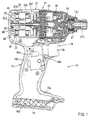
FIG.1 is a vertical sectional view of an electric power tool according to an embodiment of the present intention; -
FIG.2 is a schematic showing a configuration of the motor drive circuit of a blushless DC motor of the electric power tool; -
FIG.3(A) and FIG. 3(B) are schematic views showing electric power tools according to alternative embodiments; and -
FIG.4 is a schematic view showing a known electric power tool. - Each of the additional features and teachings disclosed above and below may be utilized separately or in conjunction with other features and teachings to provide improved electric power tools. Representative examples of the present invention, which examples utilize many of these additional features and teachings both separately and in conjunction with one another, will now be described in detail with reference to the attached drawings. This detailed description is merely intended to teach a person of skill in the art further details for practicing preferred aspects of the present teachings and is not intended to limit the scope of the invention. Only the claims define the scope of the claimed invention. Therefore, combinations of features and steps disclosed in the following detailed description may not be necessary to practice the invention in the broadest sense, and are instead taught merely to particularly describe representative examples of the invention. Moreover, various features of the representative examples and the dependent claims may be combined in ways that are not specifically enumerated in order to provide additional useful embodiments of the present teachings.
- In one embodiment, an electric power tool includes a housing body part for housing a brushless DC motor as a driving source, a grip part formed to protrude from a lateral part of the housing body part, a switch part provided in a position allowing a user to engage the switch part by his or her finger while the user holds the grip part, a battery that supplies a power to the brushless DC motor, a three-phase bridge circuit for controlling the blushless DC motor, a switching device constituting a part of the three-phase bridge circuit, and a capacitor connected in parallel with the three-phase bridge circuit. The three-phase bridge circuit is disposed proximate to the brushless DC motor in the housing body part, and the capacitor is disposed at a position proximate to a switch part or located closer to the three-phase bridge circuit than to the switch part. The electric power tool further includes an electric conductor that electrically connects the capacitor and the three-phase bridge circuit, and the three-phase bridge circuit is configured to connect the capacitor and the three-phase bridge circuit at the shortest distance.
- With this arrangement, the capacitor is disposed at a position proximate to the switch part or located closer to the three-phase bridge circuit than to the switch part. That is, the capacitor is located in the vicinity of the three-phase bridge circuit. Further, an electric conductor such as a lead wire is configured such that the capacitor and the three-phase circuit are connected at the shortest distance. Thus, the length of the electric conductor such as a lead wire that connects the capacitor and the three-phase bridge circuit can be made as short as possible. Consequently, the inductance component (L) of the electric conductor becomes small and a surge voltage, which is caused by the inductance component (L) when an operation of the switching device having the three-phase bridge circuit part is made, becomes small (e=Ldi/dt). Therefore, the withstand voltage of the switching device becomes small and the capacity of the capacitor becomes relatively small.
- Therefore, a withstand voltage of the switching device can be lowered and the capacity of a capacitor can be made relatively small as much as possible by suppressing a surge voltage caused by the operation of the switching device.
- The three-phase bridge circuit may be positioned on a rear side of the brushless DC motor and the capacitor is mounted on an electrical circuit board of the switch part or to terminals thereof.
- Since the three-phase bridge circuit part is positioned on a rear side of the brushless DC motor in this way, the switching device can be effectively cooled down by a motor cooling fan.
- Further, since the capacitor is mounted on the electrical circuit board of the switch part or to the terminals thereof and is located outside the housing body part, the housing body part can be made compact.
- The three-phase bridge may be positioned on a rear side of the brushless DC motor and the capacitor may be positioned at the boundary region between the housing body part and the grip part.
- Thus, since the capacitor is positioned at the boundary region between the housing body part and the grip part, the lead wire etc. can be made short in comparison with the case where the capacitor is mounted on the electrical circuit board of the switch part.
- The three-phase bridge circuit may be located in the rear of the brushless DC motor and the capacitor is mounted on the electrical circuit board on which the three-phase bridge circuit part is mounted.
- Thus, the length of the electric conductor between the capacitor and the three-phase bridge circuit part can be minimized.
- An electric power tool according to an embodiment of the present invention will be described below with reference to
FIG.1 to FIG.3(A) andFIG. 3(B) . The electric power tool of the present embodiment is a rotary impact tool, in particular, an impact driver that is driven by a blushless DC motor. - As shown in
FIG.1 , ahousing 11 of anelectric power tool 10 according to the present embodiment includes a tubularhousing body part 12, and agrip part 15 formed to protrude from a lateral part of the housing body part 12 (lower part inFIG.1 ). Thegrip part 15 includes ahandgrip part 15h that can be grasped by a user when using theelectric power tool 10, and alower part 15p located on the side of the protruding end (lower end) of thehandgrip part 15h. Atrigger switch part 18 is provided at the base end portion of thehandgrip part 15h and can be pulled by a user with his or her finger. - Further, the
lower part 15p of thegrip part 15 can be opened in a front-back direction with respect to thehandgrip part 15h, and a connectingpart 16 for a battery pack is provided on the lower side of thelower part 15p for connecting the battery pack (not shown). - Within the
housing body part 12, abrushless motor 20, aplanetary gear train 24, aspindle 25, a strikingpower generation mechanism 26, and ananvil 27 are housed coaxially in this order from the rear side of thehousing body part 12. A rotative power of thebrushless DC motor 20 is transmitted to thespindle 25 via theplanetary gear train 24, a rotative power of thespindle 25 is converted into a rotary striking power by the strikingpower generation mechanism 26, and then the rotary striking power is transmitted to theanvil 27. Theanvil 27 is supported by abearing 12j provided at the front end of thehousing body part 12, so that theanvil 27 can rotate about an axis but cannot move in an axial direction. At the front end of theanvil 27, achuck part 27t is provided, so that a driver bit or a socket bit, and the like (not shown) can be attached to thechuck part 27t. - As shown in
FIG.1 , thebrushless DC motor 20 includes arotor 22 having a permanent magnet, and astator 23 having adrive coil 23c. Amotor cooling fan 22f is coaxially mounted to arotational shaft 22j of themotor 22 at a position on a front side of thestator 23. Thestator 23 includes a tubular part (not shown), and sixtooth parts 23p radially protruding inward from an inner circumference surface of the cylindrical part.Drive coils 23c is wound around thetooth parts 23p via an insulating material. - Further, in a rear end part of the
stator 23, threemagnetic sensors 32 for detecting the positions of magnetic poles of therotor 22, a three-phasebridge circuit part 45 of amotor drive circuit 40, etc., are mounted on anelectrical circuit board 30. Thus, current can be supplied to the drive coils 23c in order by themotor drive circuit 40 to rotate therotor 22 while the positions of the magnetic poles of therotor 22 are detected by themagnetic sensors 32. - As shown in
FIG.2 , themotor drive circuit 40 of thebrushless DC motor 20 includes apower supply part 42, the three-phasebridge circuit part 45 including sixswitching devices 44, acontrol circuit part 46 that controls theswitching devices 44 of the three-phasebridge circuit part 45. Thepower supply part 42 is a part that receives the power supplied to theelectric power tool 10 from abattery 42v inside the battery pack viaterminals 42t of the batterypack connection part 16. Thepower supply part 42 includespower wires 42c connected to the terminal 42t and acapacitor 43c connected in parallel with thepower wires 42c - The three-phase
bridge circuit part 45 is connected to thepower wires 42c in parallel with thecapacitor 43c, and threeoutput lines 41 from the three-phase bridge circuit part 45 (hereinafter referred to as power lines 41) are connected to the corresponding windings of the drive coils 23c. For example, field effect transistors (FET) may be used as switchingdevices 44 of the three-phase bridge part 45. - The
control circuit part 46 is constituted by an electronic parts such as a microcomputer, an IC or the like that can operate theswitching devices 44 based on an actuating signal from thetrigger switch part 18. Thecontrol circuit part 46 receives signals from the above-described threemagnetic sensors 32, and based on these signals (see an outline arrow inFIG. 2 ), thecontrol circuit part 46 performs an on/off operation of each of theswitching devices 44 constituting the three-phasebridge circuit part 45. Thus, current may be supplied to the drive coils 23c of thebrushless DC motor 20 in order at a predetermined switching rate. - Further, signals from various switches, such as
switches 46a and 46b for switching the tightening speed of fasteners driven by the tool are input to thecontrol circuit part 46. - As shown in
FIG.1 , thetrigger switch part 18 includes atrigger lever 18r and anelectrical circuit board 18c that can convert the movement of thetrigger lever 18r into an electric signal and transmit it to thecontrol circuit part 46. Thecapacitor 43c of thepower supply part 42 is mounted on theelectrical circuit board 18c in an electrically isolated state. - The
capacitor 43c is connected by thepower wires 42c (at lead wire parts R inFIG.2 ) in parallel with the three-phasebridge circuit part 45 mounted on theelectrical circuit board 30 provided in the rear end part of thestator 23. The lead wire parts R connected between thecapacitor 43c and the three-phasebridge circuit part 45 are wired to have the shortest distance within thehousing 11. That is, thepower wires 42c (including the lead wire parts R) serves as the electric conductors. - According to the
electronic power tool 10 of the present embodiment, thecapacitor 43c is located in the vicinity of theswitch 18. That is, thecapacitor 43c is located relatively close to the three-phasebridge circuit part 45. Further, the electric conductors such as the lead wire parts R are configured to connect between thecapacitor 43c and the three-phasebridge circuit part 45 at the shortest distance. Thus, the length of the lead wire parts R (electric conductors) that connect between thecapacitor 43c and the three-phasebridge circuit part 45 can be made as short as possible. Consequently, the inductance component (L) of the lead wire parts R (electric conductors) becomes smaller, and a surge voltage that may be caused by the inductance component (L) when theswitching device 44 is operated can be lowered. Therefore, the withstand voltage of theswitching device 44 can be lowered, and further the capacitance of thecapacitor 43c can be relatively small. - Further, since the three-phase
bridge circuit part 45 is located on the rear side of thebrushless DC motor 20, the switchingdevice 44 can be effectively cooled down by themotor cooling fan 22f. In addition, since thecapacitor 43c is mounted on theelectrical circuit board 18c of theswitch part 18 and is located outside thehousing body part 12, thehousing body part 12 can be made compact. - The present invention may not be limited by the above-described embodiment and various changes may be made without departing from the scope of the invention. For example, the above embodiment shows that the
capacitor 43c is mounted on theelectrical circuit board 18c of theswitch part 18, but as shown inFIG.3(A) , it is possible to locate thecapacitor 43c at the boundary region between thehousing body part 12 and thegrip part 15. Thus, the length of the lead wire parts R can be minimized compared with the case where thecapacitor 43c is mounted on theelectrical circuit board 18c of theswitch part 18. - Further, as shown in
FIG.3(B) , it is possible to mount thecapacitor 43c on theelectrical circuit board 30 on which the three-phasebridge circuit part 45 is mounted. Thus, the length of the electric conductors between thecapacitor 43c and the three-phasebridge circuit part 45 can be minimized. - In the above embodiment, the rotary impact tool (an impact driver) as an example of the electric power tool is driven by the
brushless DC motor 20. However, the present invention can be applied to any other power tool, such as an electric screwdriver and an electric drill, having a brushless DC motor.
It is explicitly stated that all features disclosed in the description and/or the claims are intended to be disclosed separately and independently from each other for the purpose of original disclosure as well as for the purpose of restricting the claimed invention independent of the composition of the features in the embodiments and/or the claims. It is explicitly stated that all value ranges or indications of groups of entities disclose every possible intermediate value or intermediate entity for the purpose of original disclosure as well as for the purpose of restricting the claimed invention, in particular as limits of value ranges.
Claims (14)
- An electric power tool (10), comprising:a housing body part (12) capable of housing a brushless DC motor (20) as a driving source;a grip part (15) formed to protrude from a lateral part of the housing body part (12);a switch part (18) provided in such a position that allows a user to engage a finger of the user with the switch part (18) while the user holds the grip part (15);a battery (42v) capable of supplying a power to the blushless DC motor (20);a three-phase bridge circuit (45) configured to control the blushless DC motor (20) and including switching device (44)s; anda capacitor (43c) connected in parallel with the three-phase bridge circuit (45);wherein the three-phase bridge circuit (45) is disposed proximal to the brushless DC motor (20) within the housing body part (12), and the capacitor (43c) is disposed at a position proximal to the switch part (18).
- The electric power tool according to claim 1, further comprising electric conductors (42c) electrically connecting between the capacitor (43c) and the three-phase bridge circuit (45) and configured to connect the capacitor (43c) and the three-phase bridge circuit (45) at the shortest distance.
- The electric power tool (10) according to claim 1 or 2, wherein the switch part (18) is positioned on a front side of the housing body part (12), the three-phase bridge circuit (45) is positioned on a rear side of the brushless DC motor (20), and the capacitor (43c) is mounted on an electrical circuit board (18c) of the switch part (18).
- The electric power tool (10) according to claim 1 or 2, wherein the switch part (18) is positioned on a front side of the housing body part (12), the three-phase bridge circuit (45) is positioned on a rear side of the brushless DC motor (20), and the capacitor (43c) is positioned at a boundary region between the housing body part (12) and the grip part (15).
- The electric power tool (10) according to claim 1 or 2, wherein the switch part (18) is positioned on a front side of the housing body part (12), the three-phase bridge circuit (45) is positioned on a rear side of the brushless DC motor (20), and the capacitor (43c) is mounted on an electrical circuit board (30) having the three-phase bridge circuit (45) mounted thereon.
- An electric power tool (10), comprising:a housing body part (12) capable of housing a brushless DC motor (20) as a driving source;a grip part (15) formed to protrude from a lateral part of the housing body part (12);a switch part (18) provided in such a position that allows a user to engage a finger of the user with the switch part (18) while the user holds the grip part (15);a battery (42v) capable of supplying a power to the blushless DC motor (20);a three-phase bridge circuit (45) configured to control the blushless DC motor (20) and including switching device (44)s; anda capacitor (43c) connected in parallel with the three-phase bridge circuit (45);wherein the three-phase bridge circuit (45) is disposed proximal to the brush less DC motor (20) within the housing body part (12), and the capacitor (43c) is disposed at a position closer to the three-phase bridge circuit (45) than the switch part (18).
- The electric power tool (10) according to claim 6, further comprising electric conductors (42c) electrically connecting between the capacitor (43c) and the three-phase bridge circuit (45) and configured to connect the capacitor (43c) and the three-phase bridge circuit (45) at the shortest distance.
- The electric power tool (10) according to claim 1 or 6, wherein the electric power tool (10) is a rotary impact driver.
- An electric power tool (10), comprising:a DC motor (20);a control circuit (45) capable of controlling the DC motor (20);a capacitor (43c) electrically connected to the control circuit (45);a switch (18) electrically connected to the control circuit (45), so that the DC motor (20) is driven under the control of the control circuit (45)when the switch (18) is operated;wherein the capacitor (43c) is positioned closer to the control circuit (45) than the switch (18).
- An electric power tool (10), comprising:a brushless DC motor (20) as a driving source;a control circuit for controlling the brushless DC motor (20); anda capacitor (43c) connected in parallel with the control circuit;
wherein the control circuit is positioned on a rear side of the brushless DC motor (20);the capacitor (43c) is disposed at a position proximal to the control circuit; andelectric conductors (42c) connect electrically between the capacitor (43c) and the control circuit and are configured to connect the capacitor (43c) and the control circuit at the shortest distance. - The electric power tool (10) according to claim 10, wherein the control circuit includes a three-phase bridge circuit (45).
- The electric power tool (10) according to claim 10 or 11, further comprising:a housing body part (12) capable of housing the brushless DC motor (20);a grip part (15) formed to protrude from a lateral part of the housing body part (12); anda switch part (18) provided in the grip part (15);wherein the capacitor (43c) is mounted on an electrical circuit board (18c) of the switch part (18).
- The electric power tool (10) according to claim 10 or 11, further comprising:a housing body part (12) capable of housing the brushless DC motor (20); anda grip part (15) formed to protrude from a lateral part of the housing body part (12);wherein the capacitor (43c) is positioned at a boundary region between the housing part (12) and the grip part (15).
- The electric power tool (10) according to claim 10 or 11, wherein the capacitor (43c) is mounted on an electrical circuit board (30) having the three-phase bridge circuit (45) mounted thereon.
Applications Claiming Priority (1)
| Application Number | Priority Date | Filing Date | Title |
|---|---|---|---|
| JP2008333526A JP2010155291A (en) | 2008-12-26 | 2008-12-26 | Power tool |
Publications (3)
| Publication Number | Publication Date |
|---|---|
| EP2202877A2 true EP2202877A2 (en) | 2010-06-30 |
| EP2202877A3 EP2202877A3 (en) | 2012-10-17 |
| EP2202877B1 EP2202877B1 (en) | 2016-11-23 |
Family
ID=42153709
Family Applications (1)
| Application Number | Title | Priority Date | Filing Date |
|---|---|---|---|
| EP09015999.7A Active EP2202877B1 (en) | 2008-12-26 | 2009-12-24 | Electric power tools |
Country Status (5)
| Country | Link |
|---|---|
| US (1) | US20100163266A1 (en) |
| EP (1) | EP2202877B1 (en) |
| JP (1) | JP2010155291A (en) |
| CN (1) | CN101767328B (en) |
| RU (1) | RU2442683C2 (en) |
Cited By (6)
| Publication number | Priority date | Publication date | Assignee | Title |
|---|---|---|---|---|
| GB2480351A (en) * | 2010-05-11 | 2011-11-16 | Chervon | Portable angled impact tool with switch assembly |
| EP2532489A1 (en) * | 2011-06-10 | 2012-12-12 | Makita Corporation | Electrical power tool |
| US8513838B2 (en) | 2009-05-11 | 2013-08-20 | Hitachi Koki Co., Ltd. | Electric power tool |
| EP2698913A1 (en) * | 2012-08-17 | 2014-02-19 | Andreas Stihl AG & Co. KG | Circuit for starting an electric motor within a hand held device |
| EP3090838A3 (en) * | 2011-05-19 | 2016-12-14 | Black & Decker Inc. | Power tool with force sensing electronic clutch |
| US10608501B2 (en) | 2017-05-24 | 2020-03-31 | Black & Decker Inc. | Variable-speed input unit having segmented pads for a power tool |
Families Citing this family (21)
| Publication number | Priority date | Publication date | Assignee | Title |
|---|---|---|---|---|
| JP5394895B2 (en) * | 2009-11-11 | 2014-01-22 | 株式会社マキタ | Electric tool |
| JP5549863B2 (en) * | 2010-06-08 | 2014-07-16 | 日立工機株式会社 | Battery pack and electric tool using the same |
| EP2580847B1 (en) | 2010-06-14 | 2021-11-17 | Black & Decker Inc. | Rotor assembly for brushless motor for a power tool |
| US8698430B2 (en) * | 2010-09-17 | 2014-04-15 | Makita Corporation | Variable speed switch and electric power tool with the variable speed switch mounted thereto |
| JP5936302B2 (en) | 2010-12-28 | 2016-06-22 | 日立工機株式会社 | Electric tool |
| CN103329411B (en) * | 2011-01-26 | 2017-03-01 | 株式会社牧田 | brushless motor for electric tool |
| TWI572458B (en) * | 2011-11-02 | 2017-03-01 | Max Co Ltd | Electrical tools |
| TWI458588B (en) * | 2012-03-29 | 2014-11-01 | Din Long Ind Co Ltd | Small machine tool structure |
| US9296099B2 (en) * | 2012-04-30 | 2016-03-29 | Din Long Industrial Co., Ltd. | Small machine tool |
| US9450471B2 (en) | 2012-05-24 | 2016-09-20 | Milwaukee Electric Tool Corporation | Brushless DC motor power tool with combined PCB design |
| JP5989452B2 (en) * | 2012-08-17 | 2016-09-07 | 株式会社マキタ | Electric tool |
| US20140091648A1 (en) * | 2012-10-02 | 2014-04-03 | Makita Corporation | Electric power tool |
| US10821591B2 (en) | 2012-11-13 | 2020-11-03 | Milwaukee Electric Tool Corporation | High-power cordless, hand-held power tool including a brushless direct current motor |
| WO2014132878A1 (en) * | 2013-02-26 | 2014-09-04 | 日立工機株式会社 | Electric tool |
| US9787159B2 (en) | 2013-06-06 | 2017-10-10 | Milwaukee Electric Tool Corporation | Brushless DC motor configuration for a power tool |
| JP6282546B2 (en) * | 2014-07-11 | 2018-02-21 | 株式会社マキタ | Electric tool |
| CN105515287A (en) * | 2016-02-01 | 2016-04-20 | 浙江绿动电机科技有限公司 | Water drilling tool |
| TWI676348B (en) * | 2018-05-25 | 2019-11-01 | 車王電子股份有限公司 | electrical tools |
| CN109068475B (en) * | 2018-09-07 | 2023-11-10 | 英迪迈智能驱动技术无锡股份有限公司 | PCB layout structure for cylindrical motor |
| CN113226655A (en) | 2018-12-26 | 2021-08-06 | 株式会社牧田 | Electric working machine |
| RU197538U1 (en) * | 2019-12-12 | 2020-05-13 | Публичное акционерное общество "Транснефть" (ПАО "Транснефть") | EXPLOSION POWER TOOL |
Citations (1)
| Publication number | Priority date | Publication date | Assignee | Title |
|---|---|---|---|---|
| JP2003305667A (en) | 2002-04-12 | 2003-10-28 | Nidec Shibaura Corp | Power tool |
Family Cites Families (19)
| Publication number | Priority date | Publication date | Assignee | Title |
|---|---|---|---|---|
| US3530350A (en) * | 1969-01-03 | 1970-09-22 | Skil Corp | Power system for portable electric tools including induction-type electric motor with associated solid state frequency generator |
| US4300282A (en) * | 1979-08-16 | 1981-11-17 | Amp Inc. | Free standing insertion tool |
| JPS6020870A (en) * | 1983-07-12 | 1985-02-02 | 日立工機株式会社 | Control system of clutch type motorized clamping tool |
| US5471865A (en) * | 1993-09-09 | 1995-12-05 | Gemcor Engineering Corp. | High energy impact riveting apparatus and method |
| US5458159A (en) * | 1993-12-17 | 1995-10-17 | Cooper Industries, Inc. | Shielded electrically powered wire wrap tool |
| CN2192444Y (en) * | 1994-03-04 | 1995-03-22 | 黄陈淑霞 | Simple electric tool with screw assemble and disassemble |
| JPH07314351A (en) * | 1994-05-26 | 1995-12-05 | Matsushita Electric Works Ltd | Power tool having dynamic braking function |
| JP2723055B2 (en) * | 1994-10-21 | 1998-03-09 | 日本電気株式会社 | Power circuit |
| JP3264157B2 (en) * | 1995-12-01 | 2002-03-11 | 日立工機株式会社 | Rotary impact tool |
| DE19547332A1 (en) * | 1995-12-19 | 1997-06-26 | Bosch Gmbh Robert | Electric hand machine tool |
| GB9808825D0 (en) * | 1998-04-24 | 1998-06-24 | Nimbus Communications Int Ltd | A disk recording system and a method of controlling the rotation of a turntable in such a disk recording system |
| JP4649003B2 (en) * | 1998-12-11 | 2011-03-09 | 日本電産シバウラ株式会社 | Electric tool wiring structure |
| US6536536B1 (en) * | 1999-04-29 | 2003-03-25 | Stephen F. Gass | Power tools |
| DE19938176A1 (en) * | 1999-08-16 | 2001-03-08 | Bosch Gmbh Robert | Hand tool |
| DE60135166D1 (en) * | 2000-03-16 | 2008-09-11 | Makita Corp | machine tools |
| JP2003209960A (en) * | 2002-01-15 | 2003-07-25 | Nidec Shibaura Corp | Power tool |
| US20040155532A1 (en) * | 2003-02-07 | 2004-08-12 | Brotto Daniele C. | Method for sensing switch closure to prevent inadvertent startup |
| KR20070097427A (en) * | 2004-11-01 | 2007-10-04 | 수페리어 툴 코퍼레이션 | Powered hand held devices |
| JP2008173716A (en) * | 2007-01-18 | 2008-07-31 | Max Co Ltd | Electric power tool having brushless motor |
-
2008
- 2008-12-26 JP JP2008333526A patent/JP2010155291A/en active Pending
-
2009
- 2009-10-14 CN CN2009102058222A patent/CN101767328B/en active Active
- 2009-12-24 EP EP09015999.7A patent/EP2202877B1/en active Active
- 2009-12-24 US US12/654,598 patent/US20100163266A1/en not_active Abandoned
- 2009-12-25 RU RU2009148547/02A patent/RU2442683C2/en active
Patent Citations (1)
| Publication number | Priority date | Publication date | Assignee | Title |
|---|---|---|---|---|
| JP2003305667A (en) | 2002-04-12 | 2003-10-28 | Nidec Shibaura Corp | Power tool |
Cited By (10)
| Publication number | Priority date | Publication date | Assignee | Title |
|---|---|---|---|---|
| US8513838B2 (en) | 2009-05-11 | 2013-08-20 | Hitachi Koki Co., Ltd. | Electric power tool |
| EP2251148B1 (en) * | 2009-05-11 | 2017-11-29 | Hitachi Koki Co., Ltd. | Electric power tool |
| GB2480351A (en) * | 2010-05-11 | 2011-11-16 | Chervon | Portable angled impact tool with switch assembly |
| EP3090838A3 (en) * | 2011-05-19 | 2016-12-14 | Black & Decker Inc. | Power tool with force sensing electronic clutch |
| US10256697B2 (en) | 2011-05-19 | 2019-04-09 | Black & Decker Inc. | Electronic switching module for a power tool |
| US10651706B2 (en) | 2011-05-19 | 2020-05-12 | Black & Decker Inc. | Control unit for a power tool |
| EP2532489A1 (en) * | 2011-06-10 | 2012-12-12 | Makita Corporation | Electrical power tool |
| RU2594230C2 (en) * | 2011-06-10 | 2016-08-10 | Макита Корпорейшн | Electric driven tool |
| EP2698913A1 (en) * | 2012-08-17 | 2014-02-19 | Andreas Stihl AG & Co. KG | Circuit for starting an electric motor within a hand held device |
| US10608501B2 (en) | 2017-05-24 | 2020-03-31 | Black & Decker Inc. | Variable-speed input unit having segmented pads for a power tool |
Also Published As
| Publication number | Publication date |
|---|---|
| RU2442683C2 (en) | 2012-02-20 |
| CN101767328A (en) | 2010-07-07 |
| RU2009148547A (en) | 2011-06-27 |
| EP2202877B1 (en) | 2016-11-23 |
| CN101767328B (en) | 2012-01-18 |
| US20100163266A1 (en) | 2010-07-01 |
| JP2010155291A (en) | 2010-07-15 |
| EP2202877A3 (en) | 2012-10-17 |
Similar Documents
| Publication | Publication Date | Title |
|---|---|---|
| EP2202877B1 (en) | Electric power tools | |
| US9621009B2 (en) | Electric power tool including a plurality of circuit boards | |
| EP2100702B1 (en) | Electrical power tools | |
| US11090784B2 (en) | Screw-tightening power tool | |
| US9812930B2 (en) | Control unit for a power tool | |
| EP2913158B1 (en) | Electrical power tool | |
| JP4981345B2 (en) | Electric tool | |
| WO2016067997A1 (en) | Powered working machine | |
| US11418094B2 (en) | Electric tool | |
| JP2014113664A (en) | Electric power tool | |
| JP5332163B2 (en) | Electric tool | |
| JP5727064B2 (en) | Electric tool | |
| JP2013000863A (en) | Electric tool | |
| JP6507773B2 (en) | Hand-held power tool | |
| US20230041179A1 (en) | Switch module for a power tool | |
| JP5840713B2 (en) | Electric tool | |
| JP5529229B2 (en) | Electric tool | |
| CN116111782A (en) | Motor controller for tool |
Legal Events
| Date | Code | Title | Description |
|---|---|---|---|
| PUAI | Public reference made under article 153(3) epc to a published international application that has entered the european phase |
Free format text: ORIGINAL CODE: 0009012 |
|
| AK | Designated contracting states |
Kind code of ref document: A2 Designated state(s): AT BE BG CH CY CZ DE DK EE ES FI FR GB GR HR HU IE IS IT LI LT LU LV MC MK MT NL NO PL PT RO SE SI SK SM TR |
|
| AX | Request for extension of the european patent |
Extension state: AL BA RS |
|
| PUAL | Search report despatched |
Free format text: ORIGINAL CODE: 0009013 |
|
| AK | Designated contracting states |
Kind code of ref document: A3 Designated state(s): AT BE BG CH CY CZ DE DK EE ES FI FR GB GR HR HU IE IS IT LI LT LU LV MC MK MT NL NO PL PT RO SE SI SK SM TR |
|
| AX | Request for extension of the european patent |
Extension state: AL BA RS |
|
| RIC1 | Information provided on ipc code assigned before grant |
Ipc: H02K 11/00 20060101ALI20120912BHEP Ipc: B25F 5/02 20060101ALI20120912BHEP Ipc: B25F 5/00 20060101AFI20120912BHEP Ipc: H05K 1/18 20060101ALI20120912BHEP |
|
| 17P | Request for examination filed |
Effective date: 20130403 |
|
| GRAP | Despatch of communication of intention to grant a patent |
Free format text: ORIGINAL CODE: EPIDOSNIGR1 |
|
| INTG | Intention to grant announced |
Effective date: 20150715 |
|
| REG | Reference to a national code |
Ref country code: DE Ref legal event code: R079 Ref document number: 602009042567 Country of ref document: DE Free format text: PREVIOUS MAIN CLASS: H02P0006080000 Ipc: B25F0005000000 |
|
| RIC1 | Information provided on ipc code assigned before grant |
Ipc: H05K 1/18 20060101ALI20160309BHEP Ipc: B25F 5/02 20060101ALI20160309BHEP Ipc: B25F 5/00 20060101AFI20160309BHEP Ipc: H02K 11/33 20160101ALI20160309BHEP |
|
| GRAP | Despatch of communication of intention to grant a patent |
Free format text: ORIGINAL CODE: EPIDOSNIGR1 |
|
| INTG | Intention to grant announced |
Effective date: 20160513 |
|
| GRAJ | Information related to disapproval of communication of intention to grant by the applicant or resumption of examination proceedings by the epo deleted |
Free format text: ORIGINAL CODE: EPIDOSDIGR1 |
|
| GRAR | Information related to intention to grant a patent recorded |
Free format text: ORIGINAL CODE: EPIDOSNIGR71 |
|
| GRAS | Grant fee paid |
Free format text: ORIGINAL CODE: EPIDOSNIGR3 |
|
| GRAA | (expected) grant |
Free format text: ORIGINAL CODE: 0009210 |
|
| INTC | Intention to grant announced (deleted) | ||
| AK | Designated contracting states |
Kind code of ref document: B1 Designated state(s): AT BE BG CH CY CZ DE DK EE ES FI FR GB GR HR HU IE IS IT LI LT LU LV MC MK MT NL NO PL PT RO SE SI SK SM TR |
|
| INTG | Intention to grant announced |
Effective date: 20161014 |
|
| REG | Reference to a national code |
Ref country code: GB Ref legal event code: FG4D |
|
| REG | Reference to a national code |
Ref country code: CH Ref legal event code: EP |
|
| REG | Reference to a national code |
Ref country code: IE Ref legal event code: FG4D |
|
| REG | Reference to a national code |
Ref country code: AT Ref legal event code: REF Ref document number: 847438 Country of ref document: AT Kind code of ref document: T Effective date: 20161215 |
|
| REG | Reference to a national code |
Ref country code: DE Ref legal event code: R096 Ref document number: 602009042567 Country of ref document: DE |
|
| REG | Reference to a national code |
Ref country code: FR Ref legal event code: PLFP Year of fee payment: 8 |
|
| PG25 | Lapsed in a contracting state [announced via postgrant information from national office to epo] |
Ref country code: LV Free format text: LAPSE BECAUSE OF FAILURE TO SUBMIT A TRANSLATION OF THE DESCRIPTION OR TO PAY THE FEE WITHIN THE PRESCRIBED TIME-LIMIT Effective date: 20161123 |
|
| REG | Reference to a national code |
Ref country code: LT Ref legal event code: MG4D |
|
| REG | Reference to a national code |
Ref country code: NL Ref legal event code: MP Effective date: 20161123 |
|
| REG | Reference to a national code |
Ref country code: AT Ref legal event code: MK05 Ref document number: 847438 Country of ref document: AT Kind code of ref document: T Effective date: 20161123 |
|
| PG25 | Lapsed in a contracting state [announced via postgrant information from national office to epo] |
Ref country code: GR Free format text: LAPSE BECAUSE OF FAILURE TO SUBMIT A TRANSLATION OF THE DESCRIPTION OR TO PAY THE FEE WITHIN THE PRESCRIBED TIME-LIMIT Effective date: 20170224 Ref country code: LT Free format text: LAPSE BECAUSE OF FAILURE TO SUBMIT A TRANSLATION OF THE DESCRIPTION OR TO PAY THE FEE WITHIN THE PRESCRIBED TIME-LIMIT Effective date: 20161123 Ref country code: SE Free format text: LAPSE BECAUSE OF FAILURE TO SUBMIT A TRANSLATION OF THE DESCRIPTION OR TO PAY THE FEE WITHIN THE PRESCRIBED TIME-LIMIT Effective date: 20161123 Ref country code: NL Free format text: LAPSE BECAUSE OF FAILURE TO SUBMIT A TRANSLATION OF THE DESCRIPTION OR TO PAY THE FEE WITHIN THE PRESCRIBED TIME-LIMIT Effective date: 20161123 Ref country code: NO Free format text: LAPSE BECAUSE OF FAILURE TO SUBMIT A TRANSLATION OF THE DESCRIPTION OR TO PAY THE FEE WITHIN THE PRESCRIBED TIME-LIMIT Effective date: 20170223 |
|
| PG25 | Lapsed in a contracting state [announced via postgrant information from national office to epo] |
Ref country code: PT Free format text: LAPSE BECAUSE OF FAILURE TO SUBMIT A TRANSLATION OF THE DESCRIPTION OR TO PAY THE FEE WITHIN THE PRESCRIBED TIME-LIMIT Effective date: 20170323 Ref country code: PL Free format text: LAPSE BECAUSE OF FAILURE TO SUBMIT A TRANSLATION OF THE DESCRIPTION OR TO PAY THE FEE WITHIN THE PRESCRIBED TIME-LIMIT Effective date: 20161123 Ref country code: BE Free format text: LAPSE BECAUSE OF NON-PAYMENT OF DUE FEES Effective date: 20161231 Ref country code: HR Free format text: LAPSE BECAUSE OF FAILURE TO SUBMIT A TRANSLATION OF THE DESCRIPTION OR TO PAY THE FEE WITHIN THE PRESCRIBED TIME-LIMIT Effective date: 20161123 Ref country code: ES Free format text: LAPSE BECAUSE OF FAILURE TO SUBMIT A TRANSLATION OF THE DESCRIPTION OR TO PAY THE FEE WITHIN THE PRESCRIBED TIME-LIMIT Effective date: 20161123 Ref country code: AT Free format text: LAPSE BECAUSE OF FAILURE TO SUBMIT A TRANSLATION OF THE DESCRIPTION OR TO PAY THE FEE WITHIN THE PRESCRIBED TIME-LIMIT Effective date: 20161123 Ref country code: FI Free format text: LAPSE BECAUSE OF FAILURE TO SUBMIT A TRANSLATION OF THE DESCRIPTION OR TO PAY THE FEE WITHIN THE PRESCRIBED TIME-LIMIT Effective date: 20161123 |
|
| PG25 | Lapsed in a contracting state [announced via postgrant information from national office to epo] |
Ref country code: SK Free format text: LAPSE BECAUSE OF FAILURE TO SUBMIT A TRANSLATION OF THE DESCRIPTION OR TO PAY THE FEE WITHIN THE PRESCRIBED TIME-LIMIT Effective date: 20161123 Ref country code: EE Free format text: LAPSE BECAUSE OF FAILURE TO SUBMIT A TRANSLATION OF THE DESCRIPTION OR TO PAY THE FEE WITHIN THE PRESCRIBED TIME-LIMIT Effective date: 20161123 Ref country code: RO Free format text: LAPSE BECAUSE OF FAILURE TO SUBMIT A TRANSLATION OF THE DESCRIPTION OR TO PAY THE FEE WITHIN THE PRESCRIBED TIME-LIMIT Effective date: 20161123 Ref country code: CZ Free format text: LAPSE BECAUSE OF FAILURE TO SUBMIT A TRANSLATION OF THE DESCRIPTION OR TO PAY THE FEE WITHIN THE PRESCRIBED TIME-LIMIT Effective date: 20161123 Ref country code: DK Free format text: LAPSE BECAUSE OF FAILURE TO SUBMIT A TRANSLATION OF THE DESCRIPTION OR TO PAY THE FEE WITHIN THE PRESCRIBED TIME-LIMIT Effective date: 20161123 |
|
| REG | Reference to a national code |
Ref country code: CH Ref legal event code: PL |
|
| REG | Reference to a national code |
Ref country code: DE Ref legal event code: R097 Ref document number: 602009042567 Country of ref document: DE |
|
| PG25 | Lapsed in a contracting state [announced via postgrant information from national office to epo] |
Ref country code: SM Free format text: LAPSE BECAUSE OF FAILURE TO SUBMIT A TRANSLATION OF THE DESCRIPTION OR TO PAY THE FEE WITHIN THE PRESCRIBED TIME-LIMIT Effective date: 20161123 Ref country code: BE Free format text: LAPSE BECAUSE OF FAILURE TO SUBMIT A TRANSLATION OF THE DESCRIPTION OR TO PAY THE FEE WITHIN THE PRESCRIBED TIME-LIMIT Effective date: 20161123 Ref country code: BG Free format text: LAPSE BECAUSE OF FAILURE TO SUBMIT A TRANSLATION OF THE DESCRIPTION OR TO PAY THE FEE WITHIN THE PRESCRIBED TIME-LIMIT Effective date: 20170223 Ref country code: IT Free format text: LAPSE BECAUSE OF FAILURE TO SUBMIT A TRANSLATION OF THE DESCRIPTION OR TO PAY THE FEE WITHIN THE PRESCRIBED TIME-LIMIT Effective date: 20161123 |
|
| PG25 | Lapsed in a contracting state [announced via postgrant information from national office to epo] |
Ref country code: MC Free format text: LAPSE BECAUSE OF FAILURE TO SUBMIT A TRANSLATION OF THE DESCRIPTION OR TO PAY THE FEE WITHIN THE PRESCRIBED TIME-LIMIT Effective date: 20161123 |
|
| PLBE | No opposition filed within time limit |
Free format text: ORIGINAL CODE: 0009261 |
|
| STAA | Information on the status of an ep patent application or granted ep patent |
Free format text: STATUS: NO OPPOSITION FILED WITHIN TIME LIMIT |
|
| REG | Reference to a national code |
Ref country code: IE Ref legal event code: MM4A |
|
| PG25 | Lapsed in a contracting state [announced via postgrant information from national office to epo] |
Ref country code: LU Free format text: LAPSE BECAUSE OF NON-PAYMENT OF DUE FEES Effective date: 20161224 Ref country code: LI Free format text: LAPSE BECAUSE OF NON-PAYMENT OF DUE FEES Effective date: 20161231 Ref country code: CH Free format text: LAPSE BECAUSE OF NON-PAYMENT OF DUE FEES Effective date: 20161231 |
|
| 26N | No opposition filed |
Effective date: 20170824 |
|
| REG | Reference to a national code |
Ref country code: FR Ref legal event code: PLFP Year of fee payment: 9 |
|
| PG25 | Lapsed in a contracting state [announced via postgrant information from national office to epo] |
Ref country code: SI Free format text: LAPSE BECAUSE OF FAILURE TO SUBMIT A TRANSLATION OF THE DESCRIPTION OR TO PAY THE FEE WITHIN THE PRESCRIBED TIME-LIMIT Effective date: 20161123 Ref country code: IE Free format text: LAPSE BECAUSE OF NON-PAYMENT OF DUE FEES Effective date: 20161224 |
|
| PG25 | Lapsed in a contracting state [announced via postgrant information from national office to epo] |
Ref country code: CY Free format text: LAPSE BECAUSE OF FAILURE TO SUBMIT A TRANSLATION OF THE DESCRIPTION OR TO PAY THE FEE WITHIN THE PRESCRIBED TIME-LIMIT Effective date: 20161123 Ref country code: HU Free format text: LAPSE BECAUSE OF FAILURE TO SUBMIT A TRANSLATION OF THE DESCRIPTION OR TO PAY THE FEE WITHIN THE PRESCRIBED TIME-LIMIT; INVALID AB INITIO Effective date: 20091224 |
|
| PG25 | Lapsed in a contracting state [announced via postgrant information from national office to epo] |
Ref country code: IS Free format text: LAPSE BECAUSE OF FAILURE TO SUBMIT A TRANSLATION OF THE DESCRIPTION OR TO PAY THE FEE WITHIN THE PRESCRIBED TIME-LIMIT Effective date: 20161123 Ref country code: TR Free format text: LAPSE BECAUSE OF FAILURE TO SUBMIT A TRANSLATION OF THE DESCRIPTION OR TO PAY THE FEE WITHIN THE PRESCRIBED TIME-LIMIT Effective date: 20161123 Ref country code: MK Free format text: LAPSE BECAUSE OF FAILURE TO SUBMIT A TRANSLATION OF THE DESCRIPTION OR TO PAY THE FEE WITHIN THE PRESCRIBED TIME-LIMIT Effective date: 20161123 |
|
| PG25 | Lapsed in a contracting state [announced via postgrant information from national office to epo] |
Ref country code: MT Free format text: LAPSE BECAUSE OF NON-PAYMENT OF DUE FEES Effective date: 20161224 |
|
| PGFP | Annual fee paid to national office [announced via postgrant information from national office to epo] |
Ref country code: GB Payment date: 20231102 Year of fee payment: 15 |
|
| PGFP | Annual fee paid to national office [announced via postgrant information from national office to epo] |
Ref country code: FR Payment date: 20231108 Year of fee payment: 15 Ref country code: DE Payment date: 20231031 Year of fee payment: 15 |