EP2204556A1 - Exhaust purification device - Google Patents
Exhaust purification device Download PDFInfo
- Publication number
- EP2204556A1 EP2204556A1 EP08842016A EP08842016A EP2204556A1 EP 2204556 A1 EP2204556 A1 EP 2204556A1 EP 08842016 A EP08842016 A EP 08842016A EP 08842016 A EP08842016 A EP 08842016A EP 2204556 A1 EP2204556 A1 EP 2204556A1
- Authority
- EP
- European Patent Office
- Prior art keywords
- mixing pipe
- gas
- particulate filter
- entry end
- opening
- Prior art date
- Legal status (The legal status is an assumption and is not a legal conclusion. Google has not performed a legal analysis and makes no representation as to the accuracy of the status listed.)
- Granted
Links
Images


Classifications
-
- F—MECHANICAL ENGINEERING; LIGHTING; HEATING; WEAPONS; BLASTING
- F01—MACHINES OR ENGINES IN GENERAL; ENGINE PLANTS IN GENERAL; STEAM ENGINES
- F01N—GAS-FLOW SILENCERS OR EXHAUST APPARATUS FOR MACHINES OR ENGINES IN GENERAL; GAS-FLOW SILENCERS OR EXHAUST APPARATUS FOR INTERNAL COMBUSTION ENGINES
- F01N3/00—Exhaust or silencing apparatus having means for purifying, rendering innocuous, or otherwise treating exhaust
- F01N3/08—Exhaust or silencing apparatus having means for purifying, rendering innocuous, or otherwise treating exhaust for rendering innocuous
- F01N3/10—Exhaust or silencing apparatus having means for purifying, rendering innocuous, or otherwise treating exhaust for rendering innocuous by thermal or catalytic conversion of noxious components of exhaust
- F01N3/18—Exhaust or silencing apparatus having means for purifying, rendering innocuous, or otherwise treating exhaust for rendering innocuous by thermal or catalytic conversion of noxious components of exhaust characterised by methods of operation; Control
- F01N3/20—Exhaust or silencing apparatus having means for purifying, rendering innocuous, or otherwise treating exhaust for rendering innocuous by thermal or catalytic conversion of noxious components of exhaust characterised by methods of operation; Control specially adapted for catalytic conversion ; Methods of operation or control of catalytic converters
- F01N3/2066—Selective catalytic reduction [SCR]
-
- B—PERFORMING OPERATIONS; TRANSPORTING
- B01—PHYSICAL OR CHEMICAL PROCESSES OR APPARATUS IN GENERAL
- B01F—MIXING, e.g. DISSOLVING, EMULSIFYING OR DISPERSING
- B01F23/00—Mixing according to the phases to be mixed, e.g. dispersing or emulsifying
- B01F23/20—Mixing gases with liquids
- B01F23/21—Mixing gases with liquids by introducing liquids into gaseous media
- B01F23/213—Mixing gases with liquids by introducing liquids into gaseous media by spraying or atomising of the liquids
- B01F23/2132—Mixing gases with liquids by introducing liquids into gaseous media by spraying or atomising of the liquids using nozzles
-
- B—PERFORMING OPERATIONS; TRANSPORTING
- B01—PHYSICAL OR CHEMICAL PROCESSES OR APPARATUS IN GENERAL
- B01F—MIXING, e.g. DISSOLVING, EMULSIFYING OR DISPERSING
- B01F25/00—Flow mixers; Mixers for falling materials, e.g. solid particles
- B01F25/10—Mixing by creating a vortex flow, e.g. by tangential introduction of flow components
-
- B—PERFORMING OPERATIONS; TRANSPORTING
- B01—PHYSICAL OR CHEMICAL PROCESSES OR APPARATUS IN GENERAL
- B01F—MIXING, e.g. DISSOLVING, EMULSIFYING OR DISPERSING
- B01F25/00—Flow mixers; Mixers for falling materials, e.g. solid particles
- B01F25/30—Injector mixers
- B01F25/31—Injector mixers in conduits or tubes through which the main component flows
- B01F25/314—Injector mixers in conduits or tubes through which the main component flows wherein additional components are introduced at the circumference of the conduit
- B01F25/3141—Injector mixers in conduits or tubes through which the main component flows wherein additional components are introduced at the circumference of the conduit with additional mixing means other than injector mixers
-
- F—MECHANICAL ENGINEERING; LIGHTING; HEATING; WEAPONS; BLASTING
- F01—MACHINES OR ENGINES IN GENERAL; ENGINE PLANTS IN GENERAL; STEAM ENGINES
- F01N—GAS-FLOW SILENCERS OR EXHAUST APPARATUS FOR MACHINES OR ENGINES IN GENERAL; GAS-FLOW SILENCERS OR EXHAUST APPARATUS FOR INTERNAL COMBUSTION ENGINES
- F01N13/00—Exhaust or silencing apparatus characterised by constructional features ; Exhaust or silencing apparatus, or parts thereof, having pertinent characteristics not provided for in, or of interest apart from, groups F01N1/00 - F01N5/00, F01N9/00, F01N11/00
- F01N13/009—Exhaust or silencing apparatus characterised by constructional features ; Exhaust or silencing apparatus, or parts thereof, having pertinent characteristics not provided for in, or of interest apart from, groups F01N1/00 - F01N5/00, F01N9/00, F01N11/00 having two or more separate purifying devices arranged in series
- F01N13/0097—Exhaust or silencing apparatus characterised by constructional features ; Exhaust or silencing apparatus, or parts thereof, having pertinent characteristics not provided for in, or of interest apart from, groups F01N1/00 - F01N5/00, F01N9/00, F01N11/00 having two or more separate purifying devices arranged in series the purifying devices are arranged in a single housing
-
- F—MECHANICAL ENGINEERING; LIGHTING; HEATING; WEAPONS; BLASTING
- F01—MACHINES OR ENGINES IN GENERAL; ENGINE PLANTS IN GENERAL; STEAM ENGINES
- F01N—GAS-FLOW SILENCERS OR EXHAUST APPARATUS FOR MACHINES OR ENGINES IN GENERAL; GAS-FLOW SILENCERS OR EXHAUST APPARATUS FOR INTERNAL COMBUSTION ENGINES
- F01N13/00—Exhaust or silencing apparatus characterised by constructional features ; Exhaust or silencing apparatus, or parts thereof, having pertinent characteristics not provided for in, or of interest apart from, groups F01N1/00 - F01N5/00, F01N9/00, F01N11/00
- F01N13/08—Other arrangements or adaptations of exhaust conduits
-
- F—MECHANICAL ENGINEERING; LIGHTING; HEATING; WEAPONS; BLASTING
- F01—MACHINES OR ENGINES IN GENERAL; ENGINE PLANTS IN GENERAL; STEAM ENGINES
- F01N—GAS-FLOW SILENCERS OR EXHAUST APPARATUS FOR MACHINES OR ENGINES IN GENERAL; GAS-FLOW SILENCERS OR EXHAUST APPARATUS FOR INTERNAL COMBUSTION ENGINES
- F01N3/00—Exhaust or silencing apparatus having means for purifying, rendering innocuous, or otherwise treating exhaust
- F01N3/02—Exhaust or silencing apparatus having means for purifying, rendering innocuous, or otherwise treating exhaust for cooling, or for removing solid constituents of, exhaust
- F01N3/021—Exhaust or silencing apparatus having means for purifying, rendering innocuous, or otherwise treating exhaust for cooling, or for removing solid constituents of, exhaust by means of filters
- F01N3/033—Exhaust or silencing apparatus having means for purifying, rendering innocuous, or otherwise treating exhaust for cooling, or for removing solid constituents of, exhaust by means of filters in combination with other devices
- F01N3/035—Exhaust or silencing apparatus having means for purifying, rendering innocuous, or otherwise treating exhaust for cooling, or for removing solid constituents of, exhaust by means of filters in combination with other devices with catalytic reactors, e.g. catalysed diesel particulate filters
-
- F—MECHANICAL ENGINEERING; LIGHTING; HEATING; WEAPONS; BLASTING
- F01—MACHINES OR ENGINES IN GENERAL; ENGINE PLANTS IN GENERAL; STEAM ENGINES
- F01N—GAS-FLOW SILENCERS OR EXHAUST APPARATUS FOR MACHINES OR ENGINES IN GENERAL; GAS-FLOW SILENCERS OR EXHAUST APPARATUS FOR INTERNAL COMBUSTION ENGINES
- F01N3/00—Exhaust or silencing apparatus having means for purifying, rendering innocuous, or otherwise treating exhaust
- F01N3/08—Exhaust or silencing apparatus having means for purifying, rendering innocuous, or otherwise treating exhaust for rendering innocuous
- F01N3/10—Exhaust or silencing apparatus having means for purifying, rendering innocuous, or otherwise treating exhaust for rendering innocuous by thermal or catalytic conversion of noxious components of exhaust
- F01N3/105—General auxiliary catalysts, e.g. upstream or downstream of the main catalyst
- F01N3/106—Auxiliary oxidation catalysts
-
- F—MECHANICAL ENGINEERING; LIGHTING; HEATING; WEAPONS; BLASTING
- F01—MACHINES OR ENGINES IN GENERAL; ENGINE PLANTS IN GENERAL; STEAM ENGINES
- F01N—GAS-FLOW SILENCERS OR EXHAUST APPARATUS FOR MACHINES OR ENGINES IN GENERAL; GAS-FLOW SILENCERS OR EXHAUST APPARATUS FOR INTERNAL COMBUSTION ENGINES
- F01N3/00—Exhaust or silencing apparatus having means for purifying, rendering innocuous, or otherwise treating exhaust
- F01N3/08—Exhaust or silencing apparatus having means for purifying, rendering innocuous, or otherwise treating exhaust for rendering innocuous
- F01N3/10—Exhaust or silencing apparatus having means for purifying, rendering innocuous, or otherwise treating exhaust for rendering innocuous by thermal or catalytic conversion of noxious components of exhaust
- F01N3/105—General auxiliary catalysts, e.g. upstream or downstream of the main catalyst
- F01N3/108—Auxiliary reduction catalysts
-
- F—MECHANICAL ENGINEERING; LIGHTING; HEATING; WEAPONS; BLASTING
- F01—MACHINES OR ENGINES IN GENERAL; ENGINE PLANTS IN GENERAL; STEAM ENGINES
- F01N—GAS-FLOW SILENCERS OR EXHAUST APPARATUS FOR MACHINES OR ENGINES IN GENERAL; GAS-FLOW SILENCERS OR EXHAUST APPARATUS FOR INTERNAL COMBUSTION ENGINES
- F01N3/00—Exhaust or silencing apparatus having means for purifying, rendering innocuous, or otherwise treating exhaust
- F01N3/08—Exhaust or silencing apparatus having means for purifying, rendering innocuous, or otherwise treating exhaust for rendering innocuous
- F01N3/10—Exhaust or silencing apparatus having means for purifying, rendering innocuous, or otherwise treating exhaust for rendering innocuous by thermal or catalytic conversion of noxious components of exhaust
- F01N3/24—Exhaust or silencing apparatus having means for purifying, rendering innocuous, or otherwise treating exhaust for rendering innocuous by thermal or catalytic conversion of noxious components of exhaust characterised by constructional aspects of converting apparatus
- F01N3/28—Construction of catalytic reactors
- F01N3/2892—Exhaust flow directors or the like, e.g. upstream of catalytic device
-
- B—PERFORMING OPERATIONS; TRANSPORTING
- B01—PHYSICAL OR CHEMICAL PROCESSES OR APPARATUS IN GENERAL
- B01F—MIXING, e.g. DISSOLVING, EMULSIFYING OR DISPERSING
- B01F25/00—Flow mixers; Mixers for falling materials, e.g. solid particles
- B01F2025/93—Arrangements, nature or configuration of flow guiding elements
- B01F2025/931—Flow guiding elements surrounding feed openings, e.g. jet nozzles
-
- F—MECHANICAL ENGINEERING; LIGHTING; HEATING; WEAPONS; BLASTING
- F01—MACHINES OR ENGINES IN GENERAL; ENGINE PLANTS IN GENERAL; STEAM ENGINES
- F01N—GAS-FLOW SILENCERS OR EXHAUST APPARATUS FOR MACHINES OR ENGINES IN GENERAL; GAS-FLOW SILENCERS OR EXHAUST APPARATUS FOR INTERNAL COMBUSTION ENGINES
- F01N2240/00—Combination or association of two or more different exhaust treating devices, or of at least one such device with an auxiliary device, not covered by indexing codes F01N2230/00 or F01N2250/00, one of the devices being
- F01N2240/20—Combination or association of two or more different exhaust treating devices, or of at least one such device with an auxiliary device, not covered by indexing codes F01N2230/00 or F01N2250/00, one of the devices being a flow director or deflector
-
- F—MECHANICAL ENGINEERING; LIGHTING; HEATING; WEAPONS; BLASTING
- F01—MACHINES OR ENGINES IN GENERAL; ENGINE PLANTS IN GENERAL; STEAM ENGINES
- F01N—GAS-FLOW SILENCERS OR EXHAUST APPARATUS FOR MACHINES OR ENGINES IN GENERAL; GAS-FLOW SILENCERS OR EXHAUST APPARATUS FOR INTERNAL COMBUSTION ENGINES
- F01N2470/00—Structure or shape of gas passages, pipes or tubes
- F01N2470/18—Structure or shape of gas passages, pipes or tubes the axis of inlet or outlet tubes being other than the longitudinal axis of apparatus
-
- F—MECHANICAL ENGINEERING; LIGHTING; HEATING; WEAPONS; BLASTING
- F01—MACHINES OR ENGINES IN GENERAL; ENGINE PLANTS IN GENERAL; STEAM ENGINES
- F01N—GAS-FLOW SILENCERS OR EXHAUST APPARATUS FOR MACHINES OR ENGINES IN GENERAL; GAS-FLOW SILENCERS OR EXHAUST APPARATUS FOR INTERNAL COMBUSTION ENGINES
- F01N2470/00—Structure or shape of gas passages, pipes or tubes
- F01N2470/22—Inlet and outlet tubes being positioned on the same side of the apparatus
-
- F—MECHANICAL ENGINEERING; LIGHTING; HEATING; WEAPONS; BLASTING
- F01—MACHINES OR ENGINES IN GENERAL; ENGINE PLANTS IN GENERAL; STEAM ENGINES
- F01N—GAS-FLOW SILENCERS OR EXHAUST APPARATUS FOR MACHINES OR ENGINES IN GENERAL; GAS-FLOW SILENCERS OR EXHAUST APPARATUS FOR INTERNAL COMBUSTION ENGINES
- F01N2610/00—Adding substances to exhaust gases
- F01N2610/02—Adding substances to exhaust gases the substance being ammonia or urea
-
- Y—GENERAL TAGGING OF NEW TECHNOLOGICAL DEVELOPMENTS; GENERAL TAGGING OF CROSS-SECTIONAL TECHNOLOGIES SPANNING OVER SEVERAL SECTIONS OF THE IPC; TECHNICAL SUBJECTS COVERED BY FORMER USPC CROSS-REFERENCE ART COLLECTIONS [XRACs] AND DIGESTS
- Y02—TECHNOLOGIES OR APPLICATIONS FOR MITIGATION OR ADAPTATION AGAINST CLIMATE CHANGE
- Y02T—CLIMATE CHANGE MITIGATION TECHNOLOGIES RELATED TO TRANSPORTATION
- Y02T10/00—Road transport of goods or passengers
- Y02T10/10—Internal combustion engine [ICE] based vehicles
- Y02T10/12—Improving ICE efficiencies
Definitions
- the present invention relates to an exhaust emission control device.
- a particulate filter for capturing particulates in exhaust gas is incorporated in an exhaust pipe and a selective reduction catalyst capable of selectively reacting NO x with ammonia even in the presence of oxygen is arranged downstream of the particulate filter, urea water as reducing agent being added between the selective reduction catalyst and the particulate filter, thereby attaining lessening of both the particulates and NO x .
- Such addition of the urea water to the selective reduction catalyst is conducted between the particulate filter and the selective reduction catalyst.
- it is necessary to prolong a distance between a urea water added position and the selective reduction catalyst.
- such arrangement of the particulate filter and the selective reduction catalyst substantially spaced apart from each other will extremely impair the mountability on a vehicle.
- a compact exhaust emission control device as shown in Figs. 1 and 2 has been proposed by the inventor as Japanese patent application No. 2007-29923 .
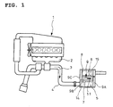
- a particulate filter 5 housed in a casing 7 to capture particles in the exhaust gas 3; arranged downstream of and in parallel with the particulate filter 5 and housed in a casing 8 is a selective reduction catalyst 6 having a property capable of selectively reacting NO x with ammonia even in the presence of oxygen.
- a discharge end of the particulate filter 5 is connected to an entry end of the selective reduction catalyst 6 through an S-shaped communication passage 9 such that the exhaust gas 3 discharged through the discharge end of the particulate filter 5 is reversely curved back into the entry end of the adjacent selective reduction catalyst 6.
- the communication passage 9 is the S-shaped structure comprising a gas gathering chamber 9A which encircles the discharge end of the particulate filter 5 to gather the exhaust gas 3 just discharged from the discharge end of the particulate filter 5 through substantially perpendicular turnabout of the gas, a mixing pipe 9B which extracts the gathered exhaust gas 3_ from the chamber 9A in a direction reverse to the flow of the exhaust in the particulate filter 5 and which is provided with a urea water addition injector 11 (urea water addition means) intermediately of the mixing pipe and a gas dispersing chamber 9C which encircles the entry end of the selective reduction catalyst 6 so as to disperse the gas 3 guided by the mixing pipe 9B through substantially perpendicular turnabout of the gas into the entry end of the selective reduction catalyst 6.
- a gas gathering chamber 9A which encircles the discharge end of the particulate filter 5 to gather the exhaust gas 3 just discharged from the discharge end of the particulate filter 5 through substantially perpendicular turnabout of the gas
- an oxidation catalyst 14 for oxidization treatment of unburned fuel in the exhaust gas 3
- an ammonia lessening catalyst 15 for oxidization treatment of surplus ammonia.
- particulates in the exhaust gas 3 are captured by the particulate filter 5.
- the urea water is added intermediately of the mixing pipe 9B and downstream of the filter into the exhaust gas 3 by the injector 11 and is pyrolyzed into ammonia and carbon dioxide gas, so that NO x in the exhaust gas 3 is favorably reduced and depurated by the ammonia on the selective reduction catalyst 6.
- both the particulates and NO x in the exhaust gas 3 are lessened.
- the exhaust gas 3 discharged through the discharge end of the particulate filter 5 is reversely curved back by the communication passage 9 into the entry end of the adjacent selective reduction catalyst 6.
- enough reaction time is ensured for production of ammonia from the urea water since a long distance between the urea water added position intermediately of the communication passage 9 and the selective reduction catalyst 6 is ensured and the flow of the exhaust gas 3 becomes turbulent due to the reversed curving to facilitate mixing of the urea water with the exhaust gas 3.
- the particulate filter 5 and selective reduction catalyst 6 are arranged in parallel with each other and the communication passage 9 is arranged between and along the particulate filter 5 and selective reduction catalyst 6, so that the whole structure becomes compact in size to substantially enhance its mountability on a vehicle.
- the mixing pipe 9B is provided midway with a boss 10 branching slantingly to upstream side. Fitted from outside of the mixing pipe 9B into the boss 10 is a urea water addition injector 11. With the injector 11 protected so as not to be directly exposed to the flow of the hot exhaust gas 3, urea water is added so that, where the exhaust gas 3 has increased flow rate as shown in Fig. 3 , the urea water added by the injector 11 is forced by the vigorous flow of the exhaust gas 3 to be biased along an inner wall of the mixing pipe 9B, disadvantageously failing in sufficient dispersion of the urea water.
- a side surface of the entry end of the mixing pipe 9B adjacent to the discharge end of the particulate filter 5 is formed with an opening 12.
- Gas guide passages 13 for introduction of all of the exhaust gas 3 from the discharge end of the particulate filter 5 tangentially into the opening 12 are formed, using guide fins 16a and 16b and a part of the discharge end of the gas gathering chamber 9A.
- a urea water addition injector 11 is coaxially fitted to an entry end face of the mixing pipe 9B so as to add the urea water axially of the entry end of the mixing pipe 9B.
- the exhaust gas 3 tangentially flows into the opening 12 to make a spiral flow in the mixing pipe 9B, which facilitates dispersion of the urea water axially added to the entry end face of the mixing pipe 9B by the urea water addition injector 11 and facilitates collision of the urea water against an inner periphery of the mixing pipe 9B; as a result, mist particles of the urea water are effectively miniaturized and early decomposed into ammonia and carbon dioxide gas.
- Patent Literature 1 As a prior art literature pertinent to the invention, there already exists, for example, the following Patent Literature 1.
- the invention was made in view of the above and has its object to provide an exhaust emission control device which eliminates the use of a heat-retention structure using heat-insulating material such as glass wool to attain substantial lessening in production cost.
- the invention is directed to an exhaust emission control device comprising a particulate filter, a selective reduction catalyst arranged downstream of the particulate filter and capable of selectively reacting NO x with ammonia even in the presence of oxygen and a communication passage for introduction of exhaust gas from a discharge side of the particulate filter to an entry side of the selective reduction catalyst, an upstream portion of said communication passage being constituted by a gas gathering chamber for surrounding a discharge end of the particulate filter to gather the exhaust gas from said discharge end through substantial perpendicular turnabout of the gas and a mixing pipe for extracting the gathered exhaust gas from said gas gathering chamber again through substantial perpendicular turnabout of the gas, urea water being addible axially of the entry end of the mixing pipe, characterized in that a discharge end of the gas gathering chamber is connected to the entry end of the mixing pipe so as to encase the entry end of the mixing pipe and close an opened end face of said entry end in a spaced-apart relationship, an opening being formed at an appropriate position on the entry end of said mixing
- the exhaust gas from the discharge end of the particulate filter is gathered in the gas gathering chamber through substantially perpendicular turnabout of the gas and is extracted by mixing pipe again through substantially perpendicular turnabout of the gas.
- the exhaust gas is tangentially introduced into the opening formed on the entry end of the mixing pipe to make a swirling flow in the mixing pipe, which facilitates dispersion of the urea water added axially into the entry end of the mixing pipe and facilitates collision of the urea water against the inner periphery of the mixing pipe; as a result, mist particles of the urea water are effectively miniaturized and early decomposed into ammonia and carbon dioxide gas.
- portions other than the opening on the entry end of the mixing pipe is surrounded by the heat-retention chamber so that heat release to outside is significantly suppressed.
- the inner periphery of the entry end of the mixing pipe is kept high-temperatured, and the colliding urea water is prevented from depositing as solid urea without decomposition into ammonia.
- the entry end of the mixing pipe is circumferentially cut in to provide a U-shaped notch line and an rectangular portion defined by the notch line is bent radially outward to provide the opening, the bent rectangular portion being employed as a mostdownstream guide fin for tangential introduction of the exhaust gas from the discharge side of the particulate filter to the opening.
- any step formed by attachment of a mostdownstream guide fin as separate part to an edge of the opening is eliminated and a guide surface of the mostdownstream guide fin is made contiguous with the inner periphery of the mixing pipe, so that deviations on performance such as swirling flow strength and/or exhaust resistance associated with deviation in assembling accuracy is lessened. Assembling efficiency is also enhanced in comparison with a case where the fin is attached as separate part.
- a swirling flow is effectively formed in the entry end of the mixing pipe and the urea water is added to the swirling flow formed, which facilitates dispersion of the urea water and facilitates collision of the urea water against the inner periphery of the mixing pipe; as a result, mist particles of the urea water can be effectively miniaturized and early decomposed into ammonia and carbon dioxide gas.
- the inner periphery of the entry end of the mixing pipe can be kept high-temperatured and the colliding urea water can be favorably decomposed into ammonia without deposition as solid urea; as a result, the use of a costly heat-retention structure using heat-insulating material such as glass wool can be eliminated to attain substantial lessening in production cost.
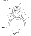
- Figs. 6 and 7 show an embodiment of the invention directed to an exhaust emission control device which has a basic structure substantially similar to that of the above-mentioned exhaust emission control device shown in Figs. 1 and 2 and which has changes as mentioned in the below as to an upstream portion of a communication passage 9 constituted by a gas gathering chamber 9A and a mixing pipe 9B.
- a discharge end of the gas gathering chamber 9A is connected to an entry end of the mixing pipe 9B so as to encase the entry end of the mixing pipe 9B and close an opened end face of the entry end in a required spaced-apart relationship.
- a side surface of the entry end of the mixing pipe 9B adjacent to the discharge side of the particulate filter 5 is formed with an opening 12.
- Gas guide passages 13 are formed in the gas gathering chamber 9A by guide fins 16a, 16b and 16c for tangential introduction of all of the exhaust gas 3 from the discharge side of the particulate filter 5 into the opening 12. An extra space isolated from the gas guide passages 13 is ensured in the gas gathering chamber 9A as a heat-retention chamber 18 surrounding the entry end of the mixing pipe 9B.
- a urea water addition injector 11 is coaxially fitted to the entry end of the mixing pipe 9B so as to add the urea water axially of the entry end of the mixing pipe 9B.
- the exhaust gas 3 from the discharge end of the particulate filter 5 is gathered in the gas gathering chamber 9A through substantially perpendicular turnabout of the gas and is extracted by the mixing pipe 9B again through substantially perpendicular turnabout of the gas.
- the exhaust gas 3 is tangentially introduced into the opening 12 formed on the entry end of the mixing pipe 9B to make a swirling flow in the mixing pipe 9B, so that when the urea water is added axially of the entry end of the mixing pipe 9B, dispersion of the urea water and collision of the urea water against the inner periphery of the mixing pipe 9B are facilitated by the swirling flow; as a result, mist particles of the urea water is effectively miniaturized and early decomposed into ammonia and carbon dioxide gas.
- the portions other than the opening 12 on the entry end of the mixing pipe 9B are surrounded by the heat-retention chamber 18 to remarkably suppress heat release to outside, so that the inner periphery of the entry end of the mixing pipe 9B is kept high-temperatured and the colliding urea water is prevented from depositing as solid urea without decomposition into ammonia.
- a swirling flow is effectively formed in the entry end of the mixing pipe 9B and the urea water is added to the swirling flow formed, which facilitates dispersion of the urea water and facilitates collision of the urea water against the inner periphery of the mixing pipe 9B; as a result, mist particles of the urea water can be effectively miniaturized and early decomposed into ammonia and carbon dioxide gas.
- the inner periphery of the entry end of the mixing pipe can be kept high-temperatured and the colliding urea water can be favorably decomposed into ammonia without deposition as solid urea; as a result, the use of costly heat-retention structure using costly heat-insulating material such as glass wool can be eliminated to attain substantial lessening in production cost.
- the mostdownstream guide fin 16c is attached as separate part to the mostdownstream edge of the opening 12.
- a step is formed by attachment of the guide fin 16c to the edge of the opening 12, so that it is feared that a degree of step is varied in association with the deviation in assembling accuracy and therefore affection on the flow of the exhaust gas 3 is varied to produce deviations on performance such as swirling flow strength and/or exhaust resistance.
- Fig. 8 in enlarged scale, a step is formed by attachment of the guide fin 16c to the edge of the opening 12, so that it is feared that a degree of step is varied in association with the deviation in assembling accuracy and therefore affection on the flow of the exhaust gas 3 is varied to produce deviations on performance such as swirling flow strength and/or exhaust resistance.
- the entry end of the mixing pipe 9B may be circumferentially cut in to provide a U-shaped notch line x, an rectangular portion defined by the notch line x being bent radially outward to provided the opening 12 as shown in Fig. 10 on the entry end of the mixing pipe 9B, the bent rectangular portion being employed as a mostdownstream guide fin 16c for tangential introduction of the exhaust gas 3 from the discharge side of the particulate filter 5 to the opening 12.
- the step formed by attachment of the mostdownstream guide fin 16c as separate part to the edge of the opening 12 is eliminated and the guide surface of the mostdownstream guide fin 16c is made contiguous with the inner periphery of the mixing pipe 9B, so that deviations on performance such as swirling flow strength and/or exhaust resistance associated with deviation of assembling accuracy are lessened. Assembling efficiency is also enhanced in comparison with a case where the fin is attached as separate part.
- the step formed by attachment of the mostdownstream guide fin 16c as separate part to the edge of the opening 12 can be eliminated and the guide surface of the mostdownstream guide fin 16c can be made contiguous with the inner periphery of the mixing pipe 9B, so that deviation on performance such as swirling flow strength and/or exhaust resistance associated with deviation in assembling accuracy can be lessened. Assembling efficiency can be also enhanced in comparison with a case where the mostdownstream guide fin 16c is attached as separate part to the edge of the opening 12.
- an exhaust emission control device of the invention is not limited to the above embodiments and that various changes and modifications may be made without departing from the scope of the invention.
- illustrated in the embodiments is a case where the exhaust gas gathered in the gas gathering chamber is extracted by the mixing pipe in a direction reverse to the flow of the exhaust in the particulate filter; however, the invention is also applicable to a structure where the exhaust gas gathered in the gas gathering chamber is extracted by the mixing pipe in a direction same as the flow of exhaust in the particulate filter.
Abstract
Description
- The present invention relates to an exhaust emission control device.
- It has been recently proposed that a particulate filter for capturing particulates in exhaust gas is incorporated in an exhaust pipe and a selective reduction catalyst capable of selectively reacting NOx with ammonia even in the presence of oxygen is arranged downstream of the particulate filter, urea water as reducing agent being added between the selective reduction catalyst and the particulate filter, thereby attaining lessening of both the particulates and NOx.
- Such addition of the urea water to the selective reduction catalyst is conducted between the particulate filter and the selective reduction catalyst. Thus, in order to ensure sufficient reaction time for pyrolysis of the urea water added to the exhaust gas into ammonia and carbon dioxide gas, it is necessary to prolong a distance between a urea water added position and the selective reduction catalyst. However, such arrangement of the particulate filter and the selective reduction catalyst substantially spaced apart from each other will extremely impair the mountability on a vehicle.
- In order to overcome this, a compact exhaust emission control device as shown in
Figs. 1 and2 has been proposed by the inventor as Japanese patent application No.2007-29923 exhaust gas 3 flows from adiesel engine 1 via an exhaust manifold 2 is aparticulate filter 5 housed in acasing 7 to capture particles in theexhaust gas 3; arranged downstream of and in parallel with theparticulate filter 5 and housed in a casing 8 is aselective reduction catalyst 6 having a property capable of selectively reacting NOx with ammonia even in the presence of oxygen. A discharge end of theparticulate filter 5 is connected to an entry end of theselective reduction catalyst 6 through an S-shaped communication passage 9 such that theexhaust gas 3 discharged through the discharge end of theparticulate filter 5 is reversely curved back into the entry end of the adjacentselective reduction catalyst 6. - As shown in
Fig. 2 which shows substantial parts in enlarged scale, the communication passage 9 is the S-shaped structure comprising agas gathering chamber 9A which encircles the discharge end of theparticulate filter 5 to gather theexhaust gas 3 just discharged from the discharge end of theparticulate filter 5 through substantially perpendicular turnabout of the gas, amixing pipe 9B which extracts the gathered exhaust gas 3_ from thechamber 9A in a direction reverse to the flow of the exhaust in theparticulate filter 5 and which is provided with a urea water addition injector 11 (urea water addition means) intermediately of the mixing pipe and agas dispersing chamber 9C which encircles the entry end of theselective reduction catalyst 6 so as to disperse thegas 3 guided by themixing pipe 9B through substantially perpendicular turnabout of the gas into the entry end of theselective reduction catalyst 6. - Arranged in the
casing 7 and in front of theparticulate filter 5 is anoxidation catalyst 14 for oxidization treatment of unburned fuel in theexhaust gas 3, and arranged in the casing 8 and behind theselective reduction catalyst 6 is an ammonia lesseningcatalyst 15 for oxidization treatment of surplus ammonia. - With such construction being employed, particulates in the
exhaust gas 3 are captured by theparticulate filter 5. The urea water is added intermediately of themixing pipe 9B and downstream of the filter into theexhaust gas 3 by theinjector 11 and is pyrolyzed into ammonia and carbon dioxide gas, so that NOx in theexhaust gas 3 is favorably reduced and depurated by the ammonia on theselective reduction catalyst 6. As a result, both the particulates and NOx in theexhaust gas 3 are lessened. - In this case, the
exhaust gas 3 discharged through the discharge end of theparticulate filter 5 is reversely curved back by the communication passage 9 into the entry end of the adjacentselective reduction catalyst 6. As a result, enough reaction time is ensured for production of ammonia from the urea water since a long distance between the urea water added position intermediately of the communication passage 9 and theselective reduction catalyst 6 is ensured and the flow of theexhaust gas 3 becomes turbulent due to the reversed curving to facilitate mixing of the urea water with theexhaust gas 3. - Moreover, the
particulate filter 5 andselective reduction catalyst 6 are arranged in parallel with each other and the communication passage 9 is arranged between and along theparticulate filter 5 andselective reduction catalyst 6, so that the whole structure becomes compact in size to substantially enhance its mountability on a vehicle. - Where the addition of the urea water to the
selective reduction catalyst 6 is to conducted between theparticulate filter 5 and thecatalyst 6 as illustrated inFigs. 1 and2 and mentioned in the above, themixing pipe 9B is provided midway with aboss 10 branching slantingly to upstream side. Fitted from outside of themixing pipe 9B into theboss 10 is a ureawater addition injector 11. With theinjector 11 protected so as not to be directly exposed to the flow of thehot exhaust gas 3, urea water is added so that, where theexhaust gas 3 has increased flow rate as shown inFig. 3 , the urea water added by theinjector 11 is forced by the vigorous flow of theexhaust gas 3 to be biased along an inner wall of themixing pipe 9B, disadvantageously failing in sufficient dispersion of the urea water. - Then, the inventor devised out as shown in
Figs. 4 and5 that a side surface of the entry end of themixing pipe 9B adjacent to the discharge end of theparticulate filter 5 is formed with anopening 12.Gas guide passages 13 for introduction of all of theexhaust gas 3 from the discharge end of theparticulate filter 5 tangentially into theopening 12 are formed, usingguide fins gas gathering chamber 9A. A ureawater addition injector 11 is coaxially fitted to an entry end face of themixing pipe 9B so as to add the urea water axially of the entry end of themixing pipe 9B. - Specifically, in this manner, the
exhaust gas 3 tangentially flows into theopening 12 to make a spiral flow in themixing pipe 9B, which facilitates dispersion of the urea water axially added to the entry end face of themixing pipe 9B by the ureawater addition injector 11 and facilitates collision of the urea water against an inner periphery of themixing pipe 9B; as a result, mist particles of the urea water are effectively miniaturized and early decomposed into ammonia and carbon dioxide gas. - As a prior art literature pertinent to the invention, there already exists, for example, the following
Patent Literature 1. - [Patent Literature 1]
JP 2005-155404A - However, with the above-mentioned structure as shown in
Figs. 4 and5 being employed, when the inner periphery of the entry end of themixing pipe 9B against which the urea water collides is cold, the colliding urea water tends to deposit as solid urea without decomposition into ammonia. In order to overcome this, an outer periphery of the discharge end of thegas gathering chamber 9A must be covered with heat-insulatingmaterial 17 such as glass wool to attain sufficient heat retention. A heat-retention structure using such heat-insulatingmaterial 17 has been a factor of high rise in production cost. - The invention was made in view of the above and has its object to provide an exhaust emission control device which eliminates the use of a heat-retention structure using heat-insulating material such as glass wool to attain substantial lessening in production cost.
- The invention is directed to an exhaust emission control device comprising a particulate filter, a selective reduction catalyst arranged downstream of the particulate filter and capable of selectively reacting NOx with ammonia even in the presence of oxygen and a communication passage for introduction of exhaust gas from a discharge side of the particulate filter to an entry side of the selective reduction catalyst, an upstream portion of said communication passage being constituted by a gas gathering chamber for surrounding a discharge end of the particulate filter to gather the exhaust gas from said discharge end through substantial perpendicular turnabout of the gas and a mixing pipe for extracting the gathered exhaust gas from said gas gathering chamber again through substantial perpendicular turnabout of the gas, urea water being addible axially of the entry end of the mixing pipe, characterized in that a discharge end of the gas gathering chamber is connected to the entry end of the mixing pipe so as to encase the entry end of the mixing pipe and close an opened end face of said entry end in a spaced-apart relationship, an opening being formed at an appropriate position on the entry end of said mixing pipe adjacent to the discharge side of the particulate filter, gas guide passages for tangential introduction of all of the exhaust gas from the discharge side of the particulate filter to said opening being formed in said gas gathering chamber by guide fins, an extra space isolated from said gas guide passages being ensured in said gas gathering chamber as a heat-retention chamber surrounding the entry end of the mixing pipe.
- Thus, in this manner, the exhaust gas from the discharge end of the particulate filter is gathered in the gas gathering chamber through substantially perpendicular turnabout of the gas and is extracted by mixing pipe again through substantially perpendicular turnabout of the gas. In this case, the exhaust gas is tangentially introduced into the opening formed on the entry end of the mixing pipe to make a swirling flow in the mixing pipe, which facilitates dispersion of the urea water added axially into the entry end of the mixing pipe and facilitates collision of the urea water against the inner periphery of the mixing pipe; as a result, mist particles of the urea water are effectively miniaturized and early decomposed into ammonia and carbon dioxide gas.
- Moreover, portions other than the opening on the entry end of the mixing pipe is surrounded by the heat-retention chamber so that heat release to outside is significantly suppressed. As a result, the inner periphery of the entry end of the mixing pipe is kept high-temperatured, and the colliding urea water is prevented from depositing as solid urea without decomposition into ammonia.
- It is preferable in the invention that the entry end of the mixing pipe is circumferentially cut in to provide a U-shaped notch line and an rectangular portion defined by the notch line is bent radially outward to provide the opening, the bent rectangular portion being employed as a mostdownstream guide fin for tangential introduction of the exhaust gas from the discharge side of the particulate filter to the opening.
- Thus, in this manner, any step formed by attachment of a mostdownstream guide fin as separate part to an edge of the opening is eliminated and a guide surface of the mostdownstream guide fin is made contiguous with the inner periphery of the mixing pipe, so that deviations on performance such as swirling flow strength and/or exhaust resistance associated with deviation in assembling accuracy is lessened. Assembling efficiency is also enhanced in comparison with a case where the fin is attached as separate part.
- According to the above-mentioned exhaust emission control device of the invention, various effects and advantages may be obtained as follows.
- (I) A swirling flow is effectively formed in the entry end of the mixing pipe and the urea water is added to the swirling flow formed, which facilitates dispersion of the urea water and facilitates collision of the urea water against the inner periphery of the mixing pipe; as a result, mist particles of the urea water can be effectively miniaturized and early decomposed into ammonia and carbon dioxide gas. Moreover, without the outer periphery of the discharge end of the gas gathering chamber being covered with heat-insulating material such as glass wool, only by ensuring the extra space isolated from the gas guide passages in the gas gathering chamber as the heat-retention chamber surrounding the entry end of the mixing pipe, the inner periphery of the entry end of the mixing pipe can be kept high-temperatured and the colliding urea water can be favorably decomposed into ammonia without deposition as solid urea; as a result, the use of a costly heat-retention structure using heat-insulating material such as glass wool can be eliminated to attain substantial lessening in production cost.
- (II) By circumferentially cutting in the entry end of the mixing pipe to provide the U-shaped notch line, by bending the rectangular portion defined by the notch line radially outward to provide the opening, and by employing the bent rectangular portion as the mostdownstream guide fin for tangential introduction of the exhaust gas from the discharge side of the particulate filter to the opening, any step formed by attachment of a mostdownstream guide fin as separate part to the edge of the opening can be eliminated and the guide surface of the guide fin can be made contiguous with the inner periphery of the mixing pipe. As a result, deviations on performance such as swirling flow strength and/or exhaust resistance associated with deviation in assembling accuracy can be lessened. Furthermore, assembling efficiency can be also enhanced in comparison with a case where the mostdownstream guide fin is attached as separate part to the edge of the opening.
-
-
Fig. 1 is a schematic view showing a conventional device; -
Fig. 2 is a perspective view showing substantial portions inFig. 1 in enlarged scale; -
Fig. 3 is a sectional view for explanation of a problem in conventional urea water addition; -
Fig. 4 is a perspective view showing partly in cutout a further conventional device proposed by the inventor; -
Fig. 5 is a sectional view looking the device shown inFig. 4 in a direction opposed to the entry end of the mixing pipe. -
Fig. 6 is a perspective view showing partly in cutout an embodiment of the invention; -
Fig. 7 is a sectional view looking the device shown inFig. 6 in a direction opposed to the entry end of the mixing pipe; -
Fig. 8 is an enlarged view showing a step formed by attachment of the guide fin to the edge of the opening; -
Fig. 9 is a side view showing a notch line cut in on the entry end of the mixing pipe; and -
Fig. 10 is a sectional view showing a further embodiment of the invention. -
- 3 exhaust gas
- 5 particulate filter
- 6 selective reduction catalyst
- 9 communication passage
- 9A gas gathering chamber
- 9B mixing pipe
- 11 urea water addition injector (urea water addition means)
- 12 opening
- 13 gas guide passage
- 16a guide fin
- 16b guide fin
- 16c guide fin
- 18 heat-retention chamber
- x notch line
- Embodiments of the invention will be described in conjunction with the drawings.
Figs. 6 and7 show an embodiment of the invention directed to an exhaust emission control device which has a basic structure substantially similar to that of the above-mentioned exhaust emission control device shown inFigs. 1 and2 and which has changes as mentioned in the below as to an upstream portion of a communication passage 9 constituted by agas gathering chamber 9A and a mixingpipe 9B. - Specifically, in the embodiment illustrated, a discharge end of the
gas gathering chamber 9A is connected to an entry end of the mixingpipe 9B so as to encase the entry end of the mixingpipe 9B and close an opened end face of the entry end in a required spaced-apart relationship. A side surface of the entry end of the mixingpipe 9B adjacent to the discharge side of theparticulate filter 5 is formed with anopening 12.Gas guide passages 13 are formed in thegas gathering chamber 9A byguide fins exhaust gas 3 from the discharge side of theparticulate filter 5 into theopening 12. An extra space isolated from thegas guide passages 13 is ensured in thegas gathering chamber 9A as a heat-retention chamber 18 surrounding the entry end of the mixingpipe 9B. - It is similar to the conventional structure proposed by the inventor and shown in
Figs. 4 and5 that a ureawater addition injector 11 is coaxially fitted to the entry end of the mixingpipe 9B so as to add the urea water axially of the entry end of the mixingpipe 9B. - With the exhaust emission control device thus constructed, the
exhaust gas 3 from the discharge end of theparticulate filter 5 is gathered in thegas gathering chamber 9A through substantially perpendicular turnabout of the gas and is extracted by the mixingpipe 9B again through substantially perpendicular turnabout of the gas. In this case, theexhaust gas 3 is tangentially introduced into theopening 12 formed on the entry end of the mixingpipe 9B to make a swirling flow in the mixingpipe 9B, so that when the urea water is added axially of the entry end of the mixingpipe 9B, dispersion of the urea water and collision of the urea water against the inner periphery of the mixingpipe 9B are facilitated by the swirling flow; as a result, mist particles of the urea water is effectively miniaturized and early decomposed into ammonia and carbon dioxide gas. - Moreover, the portions other than the
opening 12 on the entry end of the mixingpipe 9B are surrounded by the heat-retention chamber 18 to remarkably suppress heat release to outside, so that the inner periphery of the entry end of the mixingpipe 9B is kept high-temperatured and the colliding urea water is prevented from depositing as solid urea without decomposition into ammonia. - Thus, according to the above embodiment, a swirling flow is effectively formed in the entry end of the mixing
pipe 9B and the urea water is added to the swirling flow formed, which facilitates dispersion of the urea water and facilitates collision of the urea water against the inner periphery of the mixingpipe 9B; as a result, mist particles of the urea water can be effectively miniaturized and early decomposed into ammonia and carbon dioxide gas. Moreover, without the outer periphery of the discharge end of thegas gathering chamber 9A being covered with heat-insulating material such as glass wool, only by ensuring the extra space isolated from the gas guide passages in thegas gathering chamber 9A as the heat-retention chamber 18 surrounding the entry end of the mixingpipe 9B, the inner periphery of the entry end of the mixing pipe can be kept high-temperatured and the colliding urea water can be favorably decomposed into ammonia without deposition as solid urea; as a result, the use of costly heat-retention structure using costly heat-insulating material such as glass wool can be eliminated to attain substantial lessening in production cost. - In the aforementioned illustration shown in
Figs. 6 and7 , themostdownstream guide fin 16c is attached as separate part to the mostdownstream edge of theopening 12. In this case, as shown inFig. 8 in enlarged scale, a step is formed by attachment of theguide fin 16c to the edge of theopening 12, so that it is feared that a degree of step is varied in association with the deviation in assembling accuracy and therefore affection on the flow of theexhaust gas 3 is varied to produce deviations on performance such as swirling flow strength and/or exhaust resistance. In order to overcome this, as shown inFig. 9 , the entry end of the mixingpipe 9B may be circumferentially cut in to provide a U-shaped notch line x, an rectangular portion defined by the notch line x being bent radially outward to provided theopening 12 as shown inFig. 10 on the entry end of the mixingpipe 9B, the bent rectangular portion being employed as amostdownstream guide fin 16c for tangential introduction of theexhaust gas 3 from the discharge side of theparticulate filter 5 to theopening 12. - Specifically, in this manner, the step formed by attachment of the
mostdownstream guide fin 16c as separate part to the edge of theopening 12 is eliminated and the guide surface of themostdownstream guide fin 16c is made contiguous with the inner periphery of the mixingpipe 9B, so that deviations on performance such as swirling flow strength and/or exhaust resistance associated with deviation of assembling accuracy are lessened. Assembling efficiency is also enhanced in comparison with a case where the fin is attached as separate part. - Thus, according to such embodiment shown in
Figs. 9 and 10 , the step formed by attachment of themostdownstream guide fin 16c as separate part to the edge of theopening 12 can be eliminated and the guide surface of themostdownstream guide fin 16c can be made contiguous with the inner periphery of the mixingpipe 9B, so that deviation on performance such as swirling flow strength and/or exhaust resistance associated with deviation in assembling accuracy can be lessened. Assembling efficiency can be also enhanced in comparison with a case where themostdownstream guide fin 16c is attached as separate part to the edge of theopening 12. - It is to be understood that an exhaust emission control device of the invention is not limited to the above embodiments and that various changes and modifications may be made without departing from the scope of the invention. For example, illustrated in the embodiments is a case where the exhaust gas gathered in the gas gathering chamber is extracted by the mixing pipe in a direction reverse to the flow of the exhaust in the particulate filter; however, the invention is also applicable to a structure where the exhaust gas gathered in the gas gathering chamber is extracted by the mixing pipe in a direction same as the flow of exhaust in the particulate filter.
Claims (2)
- An exhaust emission control device comprising a particulate filter, a selective reduction catalyst arranged downstream of the particulate filter and capable of selectively reacting NOx with ammonia even in the presence of oxygen and a communication passage for introduction of exhaust gas from a discharge side of the particulate filter to an entry side of the selective reduction catalyst, an upstream portion of said communication passage being constituted by a gas gathering chamber for surrounding a discharge end of the particulate filter to gather the exhaust gas from said discharge end through substantial perpendicular turnabout of the gas and a mixing pipe for extracting the gathered exhaust gas from said gas gathering chamber again through substantial perpendicular turnabout of the gas, urea water being addible axially of the entry end of the mixing pipe, characterized in that a discharge end of the gas gathering chamber is connected to the entry end of the mixing pipe so as to encase the entry end of the mixing pipe and close an opened end face of said entry end in a spaced-apart relationship, an opening being formed at an appropriate position of the entry end of said mixing pipe adjacent to the discharge side of the particulate filter, gas guide passages for tangential introduction of all of the exhaust gas from the discharge side of the particulate filter to said opening being formed in said gas gathering chamber by guide fins, an extra space isolated from said gas guide passages being ensured in said gas gathering chamber as a heat-retention chamber surrounding the entry end of the mixing pipe.
- An exhaust emission control device as claimed in claim 1, characterized in that the entry end of the mixing pipe is circumferentially cut in to provide a U-shaped notch line and an rectangular portion defined by the notch line is bent radially outward to provide the opening, the bent rectangular portion being employed as mostdownstream guide fin for tangential introduction of the exhaust gas from the discharge side of the particulate filter to the opening.
Applications Claiming Priority (2)
| Application Number | Priority Date | Filing Date | Title |
|---|---|---|---|
| JP2007274566A JP4928409B2 (en) | 2007-10-23 | 2007-10-23 | Exhaust purification device |
| PCT/JP2008/002983 WO2009054123A1 (en) | 2007-10-23 | 2008-10-22 | Exhaust purification device |
Publications (3)
| Publication Number | Publication Date |
|---|---|
| EP2204556A1 true EP2204556A1 (en) | 2010-07-07 |
| EP2204556A4 EP2204556A4 (en) | 2011-06-22 |
| EP2204556B1 EP2204556B1 (en) | 2012-05-02 |
Family
ID=40579231
Family Applications (1)
| Application Number | Title | Priority Date | Filing Date |
|---|---|---|---|
| EP08842016A Active EP2204556B1 (en) | 2007-10-23 | 2008-10-22 | Exhaust emission control device |
Country Status (6)
| Country | Link |
|---|---|
| US (1) | US8245504B2 (en) |
| EP (1) | EP2204556B1 (en) |
| JP (1) | JP4928409B2 (en) |
| CN (1) | CN101835962B (en) |
| AT (1) | ATE556204T1 (en) |
| WO (1) | WO2009054123A1 (en) |
Cited By (10)
| Publication number | Priority date | Publication date | Assignee | Title |
|---|---|---|---|---|
| EP2585693A1 (en) | 2010-06-22 | 2013-05-01 | Donaldson Company, Inc. | Dosing and mixing arrangement for use in exhaust aftertreatment |
| FR3007068A3 (en) * | 2013-06-14 | 2014-12-19 | Renault Sa | CONE FLAT OF INPUT OF CATALYTIC JAR |
| US8938954B2 (en) | 2012-04-19 | 2015-01-27 | Donaldson Company, Inc. | Integrated exhaust treatment device having compact configuration |
| US9180407B2 (en) | 2008-12-17 | 2015-11-10 | Donaldson Company, Inc. | Flow device for an exhaust system |
| FR3040193A1 (en) * | 2015-08-20 | 2017-02-24 | Peugeot Citroen Automobiles Sa | SELECTIVE CATALYTIC REDUCTION SYSTEM |
| US9707525B2 (en) | 2013-02-15 | 2017-07-18 | Donaldson Company, Inc. | Dosing and mixing arrangement for use in exhaust aftertreatment |
| US9810126B2 (en) | 2010-01-12 | 2017-11-07 | Donaldson Company, Inc. | Flow device for exhaust treatment system |
| EP3517203A1 (en) * | 2018-01-26 | 2019-07-31 | Donaldson Company, Inc. | Mixing device for mixing a spray from an injector into a gas and system comprising same |
| EP3536393A3 (en) * | 2018-02-15 | 2020-01-01 | MAN Truck & Bus SE | Device for mixing exhaust gas and an additive |
| WO2020240082A1 (en) * | 2019-05-24 | 2020-12-03 | Proventia Oy | A mixer arrangement and a method of mixing for aftertreatment of exhaust gas |
Families Citing this family (34)
| Publication number | Priority date | Publication date | Assignee | Title |
|---|---|---|---|---|
| US8397492B2 (en) * | 2008-05-27 | 2013-03-19 | Hino Motors, Ltd. | Exhaust emission control device |
| JP5316796B2 (en) * | 2009-08-04 | 2013-10-16 | 三菱ふそうトラック・バス株式会社 | Engine exhaust purification system |
| JP5619430B2 (en) * | 2010-01-29 | 2014-11-05 | 日野自動車株式会社 | Exhaust purification device |
| CN105620278B (en) | 2010-06-15 | 2018-06-19 | 肖恩发展有限责任公司 | For the slot module interface of fluid reservoir |
| JP5567921B2 (en) * | 2010-07-16 | 2014-08-06 | いすゞ自動車株式会社 | Exhaust gas purification device |
| JP5567920B2 (en) * | 2010-07-16 | 2014-08-06 | いすゞ自動車株式会社 | Exhaust gas purification device |
| US20120285144A1 (en) * | 2011-05-13 | 2012-11-15 | GM Global Technology Operations LLC | Exhaust after treatment system and method for treating exhaust |
| JP6053096B2 (en) | 2012-01-12 | 2016-12-27 | 日野自動車株式会社 | Exhaust purification device |
| JP6009260B2 (en) | 2012-07-25 | 2016-10-19 | 日野自動車株式会社 | Exhaust purification device |
| DE112012006960B4 (en) * | 2012-09-28 | 2023-05-04 | Faurecia Emissions Control Technologies, Usa, Llc | Exhaust system mixing device with impactor |
| US9133601B2 (en) * | 2012-10-16 | 2015-09-15 | Komatsu Ltd. | Hydraulic excavator |
| US8794217B1 (en) * | 2013-02-07 | 2014-08-05 | Thrival Tech, LLC | Coherent-structure fuel treatment systems and methods |
| US9291081B2 (en) | 2013-05-07 | 2016-03-22 | Tenneco Automotive Operating Company Inc. | Axial flow atomization module |
| US9364790B2 (en) | 2013-05-07 | 2016-06-14 | Tenneco Automotive Operating Company Inc. | Exhaust mixing assembly |
| US9352276B2 (en) | 2013-05-07 | 2016-05-31 | Tenneco Automotive Operating Company Inc. | Exhaust mixing device |
| US9289724B2 (en) | 2013-05-07 | 2016-03-22 | Tenneco Automotive Operating Company Inc. | Flow reversing exhaust gas mixer |
| US9314750B2 (en) | 2013-05-07 | 2016-04-19 | Tenneco Automotive Operating Company Inc. | Axial flow atomization module |
| EP3102802B1 (en) * | 2014-02-07 | 2020-09-09 | Faurecia Emissions Control Technologies, USA, LLC | Mixer assembly for a vehicle exhaust system |
| USD729141S1 (en) | 2014-05-28 | 2015-05-12 | Shaw Development LLC | Diesel emissions fluid tank |
| USD729722S1 (en) | 2014-05-28 | 2015-05-19 | Shaw Development LLC | Diesel emissions fluid tank floor |
| KR101597181B1 (en) * | 2014-09-05 | 2016-03-07 | 대지금속 주식회사 | After-treatment apparatus of engine-exhaust gas used in CNG vehicle |
| WO2016044089A1 (en) * | 2014-09-15 | 2016-03-24 | Tenneco Automotive Operating Company Inc. | Axial flow atomization module with mixing device |
| DE112015004192T5 (en) * | 2014-09-15 | 2017-06-01 | Tenneco Automotive Operating Company Inc. | Exhaust gas mixing arrangement |
| US9534525B2 (en) | 2015-05-27 | 2017-01-03 | Tenneco Automotive Operating Company Inc. | Mixer assembly for exhaust aftertreatment system |
| CN107035480B (en) * | 2016-02-03 | 2019-08-09 | 天纳克(苏州)排放系统有限公司 | Mixing chamber component |
| GB2558222B (en) * | 2016-12-22 | 2019-05-29 | Perkins Engines Co Ltd | Flow hood assembly |
| JP6756644B2 (en) * | 2017-03-09 | 2020-09-16 | 日野自動車株式会社 | Exhaust purification device |
| DE102018104599B4 (en) | 2018-02-28 | 2021-06-10 | Tenneco Gmbh | Low pressure EGR system with turbo bypass |
| US10316721B1 (en) | 2018-04-23 | 2019-06-11 | Faurecia Emissions Control Technologies, Usa, Llc | High efficiency mixer for vehicle exhaust system |
| US10287948B1 (en) | 2018-04-23 | 2019-05-14 | Faurecia Emissions Control Technologies, Usa, Llc | High efficiency mixer for vehicle exhaust system |
| US10907522B2 (en) | 2018-08-03 | 2021-02-02 | Faurecia Systemes D'echappement | Internal box flow deflector for a vehicle exhaust system mixer assembly |
| CN109184867B (en) * | 2018-08-24 | 2019-11-15 | 无锡威孚力达催化净化器有限责任公司 | The cartridge type urea mixer of embedded rotating vane |
| US10787946B2 (en) | 2018-09-19 | 2020-09-29 | Faurecia Emissions Control Technologies, Usa, Llc | Heated dosing mixer |
| EP3992442B1 (en) | 2020-11-02 | 2024-01-03 | Nissin Kogyo Co., Ltd. | Exhaust gas purification device, flow path forming member, and tubular member |
Citations (3)
| Publication number | Priority date | Publication date | Assignee | Title |
|---|---|---|---|---|
| WO2004033866A1 (en) * | 2002-10-09 | 2004-04-22 | Scania Cv Ab (Publ) | Housing arranged in an exhaust gas system for a combustion engine |
| JP2005155404A (en) * | 2003-11-25 | 2005-06-16 | Komatsu Ltd | Exhaust emission control device for internal combustion engine |
| JP2008196328A (en) * | 2007-02-09 | 2008-08-28 | Hino Motors Ltd | Exhaust emission control device |
Family Cites Families (10)
| Publication number | Priority date | Publication date | Assignee | Title |
|---|---|---|---|---|
| JP3525787B2 (en) * | 1999-02-24 | 2004-05-10 | トヨタ自動車株式会社 | Exhaust gas purification device for internal combustion engine |
| SE524648C2 (en) * | 2001-09-14 | 2004-09-14 | Scania Cv Ab | Container device, including particle filter and catalyst cleaner, arranged to be provided in an exhaust system for an internal combustion engine |
| GB2381218B (en) * | 2001-10-25 | 2004-12-15 | Eminox Ltd | Gas treatment apparatus |
| JP2004108221A (en) * | 2002-09-18 | 2004-04-08 | Kubota Corp | Gas engine |
| JP4290027B2 (en) * | 2004-02-02 | 2009-07-01 | 日産ディーゼル工業株式会社 | Exhaust purification equipment |
| JP2007029923A (en) | 2005-07-29 | 2007-02-08 | Mitsui Eng & Shipbuild Co Ltd | Recovery method of printed circuit board |
| JP4462556B2 (en) * | 2005-08-04 | 2010-05-12 | 三菱ふそうトラック・バス株式会社 | Exhaust gas purification device for internal combustion engine |
| JP4928304B2 (en) * | 2007-02-23 | 2012-05-09 | 日野自動車株式会社 | Exhaust purification device |
| JP4886547B2 (en) | 2007-02-23 | 2012-02-29 | 日野自動車株式会社 | Exhaust purification device |
| JP5173308B2 (en) | 2007-07-31 | 2013-04-03 | 日野自動車株式会社 | Exhaust purification device |
-
2007
- 2007-10-23 JP JP2007274566A patent/JP4928409B2/en active Active
-
2008
- 2008-10-22 CN CN2008801126813A patent/CN101835962B/en active Active
- 2008-10-22 AT AT08842016T patent/ATE556204T1/en active
- 2008-10-22 US US12/738,994 patent/US8245504B2/en active Active
- 2008-10-22 EP EP08842016A patent/EP2204556B1/en active Active
- 2008-10-22 WO PCT/JP2008/002983 patent/WO2009054123A1/en active Application Filing
Patent Citations (3)
| Publication number | Priority date | Publication date | Assignee | Title |
|---|---|---|---|---|
| WO2004033866A1 (en) * | 2002-10-09 | 2004-04-22 | Scania Cv Ab (Publ) | Housing arranged in an exhaust gas system for a combustion engine |
| JP2005155404A (en) * | 2003-11-25 | 2005-06-16 | Komatsu Ltd | Exhaust emission control device for internal combustion engine |
| JP2008196328A (en) * | 2007-02-09 | 2008-08-28 | Hino Motors Ltd | Exhaust emission control device |
Non-Patent Citations (1)
| Title |
|---|
| See also references of WO2009054123A1 * |
Cited By (27)
| Publication number | Priority date | Publication date | Assignee | Title |
|---|---|---|---|---|
| US9180407B2 (en) | 2008-12-17 | 2015-11-10 | Donaldson Company, Inc. | Flow device for an exhaust system |
| US9925502B2 (en) | 2008-12-17 | 2018-03-27 | Donaldson Company, Inc. | Flow device for an exhaust system |
| US9810126B2 (en) | 2010-01-12 | 2017-11-07 | Donaldson Company, Inc. | Flow device for exhaust treatment system |
| US10294841B2 (en) | 2010-06-22 | 2019-05-21 | Donaldson Company, Inc. | Dosing and mixing arrangement for use in exhaust aftertreatment |
| US11608764B2 (en) | 2010-06-22 | 2023-03-21 | Donaldson Company, Inc. | Dosing and mixing arrangement for use in exhaust aftertreatment |
| US10968800B2 (en) | 2010-06-22 | 2021-04-06 | Donaldson Company, Inc. | Dosing and mixing arrangement for use in exhaust aftertreatment |
| US9670811B2 (en) | 2010-06-22 | 2017-06-06 | Donaldson Company, Inc. | Dosing and mixing arrangement for use in exhaust aftertreatment |
| EP2585693B1 (en) | 2010-06-22 | 2017-06-14 | Donaldson Company, Inc. | Dosing and mixing arrangement for use in exhaust aftertreatment |
| EP2585693B2 (en) † | 2010-06-22 | 2020-08-12 | Donaldson Company, Inc. | Dosing and mixing arrangement for use in exhaust aftertreatment |
| EP3267005B1 (en) | 2010-06-22 | 2020-12-09 | Donaldson Company, Inc. | Exhaust aftertreatment device |
| EP2585693A1 (en) | 2010-06-22 | 2013-05-01 | Donaldson Company, Inc. | Dosing and mixing arrangement for use in exhaust aftertreatment |
| US8938954B2 (en) | 2012-04-19 | 2015-01-27 | Donaldson Company, Inc. | Integrated exhaust treatment device having compact configuration |
| US9458750B2 (en) | 2012-04-19 | 2016-10-04 | Donaldson Company, Inc. | Integrated exhaust treatment device having compact configuration |
| US10245564B2 (en) | 2013-02-15 | 2019-04-02 | Donaldson Company, Inc. | Dosing and mixing arrangement for use in exhaust aftertreatment |
| US11110406B2 (en) | 2013-02-15 | 2021-09-07 | Donaldson Company, Inc. | Dosing and mixing arrangement for use in exhaust aftertreatment |
| US10603642B2 (en) | 2013-02-15 | 2020-03-31 | Donaldson Company, Inc. | Dosing and mixing arrangement for use in exhaust aftertreatment |
| US9707525B2 (en) | 2013-02-15 | 2017-07-18 | Donaldson Company, Inc. | Dosing and mixing arrangement for use in exhaust aftertreatment |
| FR3007068A3 (en) * | 2013-06-14 | 2014-12-19 | Renault Sa | CONE FLAT OF INPUT OF CATALYTIC JAR |
| FR3040193A1 (en) * | 2015-08-20 | 2017-02-24 | Peugeot Citroen Automobiles Sa | SELECTIVE CATALYTIC REDUCTION SYSTEM |
| WO2019147989A1 (en) * | 2018-01-26 | 2019-08-01 | Donaldson Company, Inc. | Mixing device for mixing a spray from an injector into a gas and system comprising same |
| US11465105B2 (en) | 2018-01-26 | 2022-10-11 | Donaldson Company, Inc. | Mixing device for mixing a spray from an injector into a gas and system comprising same |
| EP3517203A1 (en) * | 2018-01-26 | 2019-07-31 | Donaldson Company, Inc. | Mixing device for mixing a spray from an injector into a gas and system comprising same |
| US10851697B2 (en) | 2018-02-15 | 2020-12-01 | Man Truck & Bus Ag | Apparatus for mixing exhaust gas and an additive |
| EP3536393A3 (en) * | 2018-02-15 | 2020-01-01 | MAN Truck & Bus SE | Device for mixing exhaust gas and an additive |
| WO2020240082A1 (en) * | 2019-05-24 | 2020-12-03 | Proventia Oy | A mixer arrangement and a method of mixing for aftertreatment of exhaust gas |
| JP2022532453A (en) * | 2019-05-24 | 2022-07-14 | プロベンティア オーユー | Mixing device and mixing method for exhaust gas post-treatment |
| US11739676B2 (en) | 2019-05-24 | 2023-08-29 | Proventia Oy | Mixer arrangement and a method of mixing for after-treatment of exhaust gas |
Also Published As
| Publication number | Publication date |
|---|---|
| JP4928409B2 (en) | 2012-05-09 |
| CN101835962A (en) | 2010-09-15 |
| ATE556204T1 (en) | 2012-05-15 |
| EP2204556A4 (en) | 2011-06-22 |
| JP2009103019A (en) | 2009-05-14 |
| US20100257849A1 (en) | 2010-10-14 |
| WO2009054123A1 (en) | 2009-04-30 |
| EP2204556B1 (en) | 2012-05-02 |
| US8245504B2 (en) | 2012-08-21 |
| CN101835962B (en) | 2012-07-18 |
Similar Documents
| Publication | Publication Date | Title |
|---|---|---|
| EP2204556B1 (en) | Exhaust emission control device | |
| EP2128398B1 (en) | Exhaust emission control device | |
| EP2295756B1 (en) | Exhaust emission control device | |
| EP2119885B1 (en) | Exhaust emission control device | |
| EP2192284B1 (en) | Exhaust emission control device | |
| EP2518287B1 (en) | Exhaust purification device | |
| EP2184455B1 (en) | Injector mounting structure | |
| EP2187010B1 (en) | Exhaust purification apparatus | |
| US8353152B2 (en) | Exhaust emission control device | |
| JP6009260B2 (en) | Exhaust purification device | |
| CN104040130A (en) | Exhaust gas purification device | |
| EP2282028A1 (en) | Exhaust gas purification apparatus | |
| EP3594464A1 (en) | Exhaust purification apparatus | |
| US10626771B2 (en) | Mixing structure | |
| US20200040791A1 (en) | Exhaust gas purification apparatus |
Legal Events
| Date | Code | Title | Description |
|---|---|---|---|
| PUAI | Public reference made under article 153(3) epc to a published international application that has entered the european phase |
Free format text: ORIGINAL CODE: 0009012 |
|
| 17P | Request for examination filed |
Effective date: 20100419 |
|
| AK | Designated contracting states |
Kind code of ref document: A1 Designated state(s): AT BE BG CH CY CZ DE DK EE ES FI FR GB GR HR HU IE IS IT LI LT LU LV MC MT NL NO PL PT RO SE SI SK TR |
|
| AX | Request for extension of the european patent |
Extension state: AL BA MK RS |
|
| DAX | Request for extension of the european patent (deleted) | ||
| A4 | Supplementary search report drawn up and despatched |
Effective date: 20110524 |
|
| GRAP | Despatch of communication of intention to grant a patent |
Free format text: ORIGINAL CODE: EPIDOSNIGR1 |
|
| GRAS | Grant fee paid |
Free format text: ORIGINAL CODE: EPIDOSNIGR3 |
|
| GRAA | (expected) grant |
Free format text: ORIGINAL CODE: 0009210 |
|
| RTI1 | Title (correction) |
Free format text: EXHAUST EMISSION CONTROL DEVICE |
|
| AK | Designated contracting states |
Kind code of ref document: B1 Designated state(s): AT BE BG CH CY CZ DE DK EE ES FI FR GB GR HR HU IE IS IT LI LT LU LV MC MT NL NO PL PT RO SE SI SK TR |
|
| REG | Reference to a national code |
Ref country code: GB Ref legal event code: FG4D |
|
| REG | Reference to a national code |
Ref country code: AT Ref legal event code: REF Ref document number: 556204 Country of ref document: AT Kind code of ref document: T Effective date: 20120515 Ref country code: CH Ref legal event code: EP |
|
| REG | Reference to a national code |
Ref country code: IE Ref legal event code: FG4D |
|
| REG | Reference to a national code |
Ref country code: DE Ref legal event code: R096 Ref document number: 602008015437 Country of ref document: DE Effective date: 20120628 |
|
| REG | Reference to a national code |
Ref country code: NL Ref legal event code: VDEP Effective date: 20120502 |
|
| REG | Reference to a national code |
Ref country code: LT Ref legal event code: MG4D Effective date: 20120502 |
|
| PG25 | Lapsed in a contracting state [announced via postgrant information from national office to epo] |
Ref country code: FI Free format text: LAPSE BECAUSE OF FAILURE TO SUBMIT A TRANSLATION OF THE DESCRIPTION OR TO PAY THE FEE WITHIN THE PRESCRIBED TIME-LIMIT Effective date: 20120502 Ref country code: NO Free format text: LAPSE BECAUSE OF FAILURE TO SUBMIT A TRANSLATION OF THE DESCRIPTION OR TO PAY THE FEE WITHIN THE PRESCRIBED TIME-LIMIT Effective date: 20120802 Ref country code: PL Free format text: LAPSE BECAUSE OF FAILURE TO SUBMIT A TRANSLATION OF THE DESCRIPTION OR TO PAY THE FEE WITHIN THE PRESCRIBED TIME-LIMIT Effective date: 20120502 Ref country code: CY Free format text: LAPSE BECAUSE OF FAILURE TO SUBMIT A TRANSLATION OF THE DESCRIPTION OR TO PAY THE FEE WITHIN THE PRESCRIBED TIME-LIMIT Effective date: 20120502 Ref country code: SE Free format text: LAPSE BECAUSE OF FAILURE TO SUBMIT A TRANSLATION OF THE DESCRIPTION OR TO PAY THE FEE WITHIN THE PRESCRIBED TIME-LIMIT Effective date: 20120502 Ref country code: IS Free format text: LAPSE BECAUSE OF FAILURE TO SUBMIT A TRANSLATION OF THE DESCRIPTION OR TO PAY THE FEE WITHIN THE PRESCRIBED TIME-LIMIT Effective date: 20120902 Ref country code: LT Free format text: LAPSE BECAUSE OF FAILURE TO SUBMIT A TRANSLATION OF THE DESCRIPTION OR TO PAY THE FEE WITHIN THE PRESCRIBED TIME-LIMIT Effective date: 20120502 |
|
| REG | Reference to a national code |
Ref country code: AT Ref legal event code: MK05 Ref document number: 556204 Country of ref document: AT Kind code of ref document: T Effective date: 20120502 |
|
| PG25 | Lapsed in a contracting state [announced via postgrant information from national office to epo] |
Ref country code: GR Free format text: LAPSE BECAUSE OF FAILURE TO SUBMIT A TRANSLATION OF THE DESCRIPTION OR TO PAY THE FEE WITHIN THE PRESCRIBED TIME-LIMIT Effective date: 20120803 Ref country code: HR Free format text: LAPSE BECAUSE OF FAILURE TO SUBMIT A TRANSLATION OF THE DESCRIPTION OR TO PAY THE FEE WITHIN THE PRESCRIBED TIME-LIMIT Effective date: 20120502 Ref country code: SI Free format text: LAPSE BECAUSE OF FAILURE TO SUBMIT A TRANSLATION OF THE DESCRIPTION OR TO PAY THE FEE WITHIN THE PRESCRIBED TIME-LIMIT Effective date: 20120502 Ref country code: PT Free format text: LAPSE BECAUSE OF FAILURE TO SUBMIT A TRANSLATION OF THE DESCRIPTION OR TO PAY THE FEE WITHIN THE PRESCRIBED TIME-LIMIT Effective date: 20120903 Ref country code: LV Free format text: LAPSE BECAUSE OF FAILURE TO SUBMIT A TRANSLATION OF THE DESCRIPTION OR TO PAY THE FEE WITHIN THE PRESCRIBED TIME-LIMIT Effective date: 20120502 |
|
| PG25 | Lapsed in a contracting state [announced via postgrant information from national office to epo] |
Ref country code: BE Free format text: LAPSE BECAUSE OF FAILURE TO SUBMIT A TRANSLATION OF THE DESCRIPTION OR TO PAY THE FEE WITHIN THE PRESCRIBED TIME-LIMIT Effective date: 20120502 |
|
| PG25 | Lapsed in a contracting state [announced via postgrant information from national office to epo] |
Ref country code: DK Free format text: LAPSE BECAUSE OF FAILURE TO SUBMIT A TRANSLATION OF THE DESCRIPTION OR TO PAY THE FEE WITHIN THE PRESCRIBED TIME-LIMIT Effective date: 20120502 Ref country code: CZ Free format text: LAPSE BECAUSE OF FAILURE TO SUBMIT A TRANSLATION OF THE DESCRIPTION OR TO PAY THE FEE WITHIN THE PRESCRIBED TIME-LIMIT Effective date: 20120502 Ref country code: SK Free format text: LAPSE BECAUSE OF FAILURE TO SUBMIT A TRANSLATION OF THE DESCRIPTION OR TO PAY THE FEE WITHIN THE PRESCRIBED TIME-LIMIT Effective date: 20120502 Ref country code: RO Free format text: LAPSE BECAUSE OF FAILURE TO SUBMIT A TRANSLATION OF THE DESCRIPTION OR TO PAY THE FEE WITHIN THE PRESCRIBED TIME-LIMIT Effective date: 20120502 Ref country code: EE Free format text: LAPSE BECAUSE OF FAILURE TO SUBMIT A TRANSLATION OF THE DESCRIPTION OR TO PAY THE FEE WITHIN THE PRESCRIBED TIME-LIMIT Effective date: 20120502 Ref country code: AT Free format text: LAPSE BECAUSE OF FAILURE TO SUBMIT A TRANSLATION OF THE DESCRIPTION OR TO PAY THE FEE WITHIN THE PRESCRIBED TIME-LIMIT Effective date: 20120502 Ref country code: NL Free format text: LAPSE BECAUSE OF FAILURE TO SUBMIT A TRANSLATION OF THE DESCRIPTION OR TO PAY THE FEE WITHIN THE PRESCRIBED TIME-LIMIT Effective date: 20120502 |
|
| PG25 | Lapsed in a contracting state [announced via postgrant information from national office to epo] |
Ref country code: IT Free format text: LAPSE BECAUSE OF FAILURE TO SUBMIT A TRANSLATION OF THE DESCRIPTION OR TO PAY THE FEE WITHIN THE PRESCRIBED TIME-LIMIT Effective date: 20120502 |
|
| PLBE | No opposition filed within time limit |
Free format text: ORIGINAL CODE: 0009261 |
|
| STAA | Information on the status of an ep patent application or granted ep patent |
Free format text: STATUS: NO OPPOSITION FILED WITHIN TIME LIMIT |
|
| 26N | No opposition filed |
Effective date: 20130205 |
|
| PG25 | Lapsed in a contracting state [announced via postgrant information from national office to epo] |
Ref country code: ES Free format text: LAPSE BECAUSE OF FAILURE TO SUBMIT A TRANSLATION OF THE DESCRIPTION OR TO PAY THE FEE WITHIN THE PRESCRIBED TIME-LIMIT Effective date: 20120813 |
|
| REG | Reference to a national code |
Ref country code: DE Ref legal event code: R097 Ref document number: 602008015437 Country of ref document: DE Effective date: 20130205 |
|
| PG25 | Lapsed in a contracting state [announced via postgrant information from national office to epo] |
Ref country code: MC Free format text: LAPSE BECAUSE OF NON-PAYMENT OF DUE FEES Effective date: 20121031 |
|
| REG | Reference to a national code |
Ref country code: CH Ref legal event code: PL |
|
| REG | Reference to a national code |
Ref country code: IE Ref legal event code: MM4A |
|
| REG | Reference to a national code |
Ref country code: FR Ref legal event code: ST Effective date: 20130628 |
|
| PG25 | Lapsed in a contracting state [announced via postgrant information from national office to epo] |
Ref country code: IE Free format text: LAPSE BECAUSE OF NON-PAYMENT OF DUE FEES Effective date: 20121022 Ref country code: CH Free format text: LAPSE BECAUSE OF NON-PAYMENT OF DUE FEES Effective date: 20121031 Ref country code: LI Free format text: LAPSE BECAUSE OF NON-PAYMENT OF DUE FEES Effective date: 20121031 Ref country code: BG Free format text: LAPSE BECAUSE OF FAILURE TO SUBMIT A TRANSLATION OF THE DESCRIPTION OR TO PAY THE FEE WITHIN THE PRESCRIBED TIME-LIMIT Effective date: 20120802 |
|
| PG25 | Lapsed in a contracting state [announced via postgrant information from national office to epo] |
Ref country code: FR Free format text: LAPSE BECAUSE OF NON-PAYMENT OF DUE FEES Effective date: 20121031 |
|
| PG25 | Lapsed in a contracting state [announced via postgrant information from national office to epo] |
Ref country code: MT Free format text: LAPSE BECAUSE OF FAILURE TO SUBMIT A TRANSLATION OF THE DESCRIPTION OR TO PAY THE FEE WITHIN THE PRESCRIBED TIME-LIMIT Effective date: 20120502 |
|
| PG25 | Lapsed in a contracting state [announced via postgrant information from national office to epo] |
Ref country code: TR Free format text: LAPSE BECAUSE OF FAILURE TO SUBMIT A TRANSLATION OF THE DESCRIPTION OR TO PAY THE FEE WITHIN THE PRESCRIBED TIME-LIMIT Effective date: 20120502 |
|
| PG25 | Lapsed in a contracting state [announced via postgrant information from national office to epo] |
Ref country code: LU Free format text: LAPSE BECAUSE OF NON-PAYMENT OF DUE FEES Effective date: 20121022 |
|
| PG25 | Lapsed in a contracting state [announced via postgrant information from national office to epo] |
Ref country code: HU Free format text: LAPSE BECAUSE OF FAILURE TO SUBMIT A TRANSLATION OF THE DESCRIPTION OR TO PAY THE FEE WITHIN THE PRESCRIBED TIME-LIMIT Effective date: 20081022 |
|
| PGFP | Annual fee paid to national office [announced via postgrant information from national office to epo] |
Ref country code: GB Payment date: 20181017 Year of fee payment: 11 |
|
| GBPC | Gb: european patent ceased through non-payment of renewal fee |
Effective date: 20191022 |
|
| PG25 | Lapsed in a contracting state [announced via postgrant information from national office to epo] |
Ref country code: GB Free format text: LAPSE BECAUSE OF NON-PAYMENT OF DUE FEES Effective date: 20191022 |
|
| PGFP | Annual fee paid to national office [announced via postgrant information from national office to epo] |
Ref country code: DE Payment date: 20221026 Year of fee payment: 15 |