EP2206853A2 - Floor element with connection elements - Google Patents
Floor element with connection elements Download PDFInfo
- Publication number
- EP2206853A2 EP2206853A2 EP09179807A EP09179807A EP2206853A2 EP 2206853 A2 EP2206853 A2 EP 2206853A2 EP 09179807 A EP09179807 A EP 09179807A EP 09179807 A EP09179807 A EP 09179807A EP 2206853 A2 EP2206853 A2 EP 2206853A2
- Authority
- EP
- European Patent Office
- Prior art keywords
- floor
- elements
- connecting elements
- floor element
- edge
- Prior art date
- Legal status (The legal status is an assumption and is not a legal conclusion. Google has not performed a legal analysis and makes no representation as to the accuracy of the status listed.)
- Withdrawn
Links
Images


Classifications
-
- E—FIXED CONSTRUCTIONS
- E04—BUILDING
- E04F—FINISHING WORK ON BUILDINGS, e.g. STAIRS, FLOORS
- E04F15/00—Flooring
- E04F15/02—Flooring or floor layers composed of a number of similar elements
- E04F15/02161—Floor elements with grooved main surface
-
- E—FIXED CONSTRUCTIONS
- E04—BUILDING
- E04F—FINISHING WORK ON BUILDINGS, e.g. STAIRS, FLOORS
- E04F15/00—Flooring
- E04F15/02—Flooring or floor layers composed of a number of similar elements
- E04F15/02194—Flooring consisting of a number of elements carried by a non-rollable common support plate or grid
-
- E—FIXED CONSTRUCTIONS
- E04—BUILDING
- E04F—FINISHING WORK ON BUILDINGS, e.g. STAIRS, FLOORS
- E04F15/00—Flooring
- E04F15/02—Flooring or floor layers composed of a number of similar elements
- E04F15/04—Flooring or floor layers composed of a number of similar elements only of wood or with a top layer of wood, e.g. with wooden or metal connecting members
- E04F15/041—Flooring or floor layers composed of a number of similar elements only of wood or with a top layer of wood, e.g. with wooden or metal connecting members with a top layer of wood in combination with a lower layer of other material
-
- E—FIXED CONSTRUCTIONS
- E04—BUILDING
- E04F—FINISHING WORK ON BUILDINGS, e.g. STAIRS, FLOORS
- E04F15/00—Flooring
- E04F15/02—Flooring or floor layers composed of a number of similar elements
- E04F15/10—Flooring or floor layers composed of a number of similar elements of other materials, e.g. fibrous or chipped materials, organic plastics, magnesite tiles, hardboard, or with a top layer of other materials
- E04F15/105—Flooring or floor layers composed of a number of similar elements of other materials, e.g. fibrous or chipped materials, organic plastics, magnesite tiles, hardboard, or with a top layer of other materials of organic plastics with or without reinforcements or filling materials
-
- E—FIXED CONSTRUCTIONS
- E04—BUILDING
- E04F—FINISHING WORK ON BUILDINGS, e.g. STAIRS, FLOORS
- E04F2201/00—Joining sheets or plates or panels
- E04F2201/01—Joining sheets, plates or panels with edges in abutting relationship
- E04F2201/0138—Joining sheets, plates or panels with edges in abutting relationship by moving the sheets, plates or panels perpendicular to the main plane
-
- E—FIXED CONSTRUCTIONS
- E04—BUILDING
- E04F—FINISHING WORK ON BUILDINGS, e.g. STAIRS, FLOORS
- E04F2201/00—Joining sheets or plates or panels
- E04F2201/02—Non-undercut connections, e.g. tongue and groove connections
- E04F2201/021—Non-undercut connections, e.g. tongue and groove connections with separate protrusions
- E04F2201/022—Non-undercut connections, e.g. tongue and groove connections with separate protrusions with tongue or grooves alternating longitudinally along the edge
-
- E—FIXED CONSTRUCTIONS
- E04—BUILDING
- E04F—FINISHING WORK ON BUILDINGS, e.g. STAIRS, FLOORS
- E04F2201/00—Joining sheets or plates or panels
- E04F2201/03—Undercut connections, e.g. using undercut tongues or grooves
- E04F2201/035—Dovetail connections
Definitions
- the invention relates to a floor element according to the preamble of claim 1.
- the invention relates to a floor element, which consists of a molded material and is shaped as a displaceable base plate having at least four edges.
- a floor element which consists of a molded material, in particular a wood and / or plastic-containing composite material and having a top with a predetermined surface and having a bottom with a support structure, the bottom element may be formed as a displaceable bottom plate, the at least four Has edges.
- the fasteners and Jacobrastungslitis are designed in particular as tongue and groove joints and are joined together by horizontal movement, so that they snap into each other and then in the assembled state are virtually invisible.
- the proposed construction leads to frictional connections between the floor elements and allows the construction of a solid composite.
- the fasteners are also provided with holes or holes for attachment of the bottom element on a substrate, a substrate and / or substructure to allow additional fixation of the composite to the respective substrate or substructure.
- Floor elements with vertically joining fasteners are in itself from the GB 1 600 823 , of the AT 413 840 B , of the US 4,054,987 or the US 4,584,221 known. These can be combined relatively easily into a composite.
- the object of the invention is therefore to significantly improve a floor element of the type mentioned, so that the mentioned disadvantages are overcome advantageously.
- a very simple assembly and disassembly of a compound composed of several soil elements composite should be possible, the composite should be particularly well laid outdoors and used.
- each edge has a lateral surface with a plurality of connecting elements arranged thereon, which engage in a playful manner during assembly of the floor element with an adjacent floor element with its connecting elements by a vertical movement, wherein the connecting elements from the lateral surfaces extend horizontally to the outside, so that in the assembled state, taking advantage of the play-engaging engagement, a gap between the opposite edges of the bottom elements is formed.
- playful connections are made which leave a gap between the respective adjacent floor elements, through which water can flow which otherwise would accumulate on the surface.
- This combination of features creates a new floor element that can be laid as a base plate, which can be very easily assembled directly with correspondingly designed further floor elements by vertical movement.
- the floor elements are preferably square and can also be laid by laymen very easily to a composite.
- each provided on each edge fasteners can be very easily and quickly created a mechanically stable connection between each two adjacent floor elements, always leaving a gap, among other things, for drainage of possibly on the surface accumulating rainwater and the like can serve. Also, the gap causes better ventilation of the cavities forming below the underside. In addition, the gap and the aligned for a vertical movement connection technology facilitate a possible dismantling of assembled floor elements.
- the floor elements or panels can be laid both in the same direction as well as alternately in opposite directions or rotated by 90 degrees orientation. This results in very different laying patterns.
- the functional as well as optical attractiveness is increased in particular by the fact that the upper sides of the floor elements can have different surface structures and / or colors and / or orientation.
- the connecting elements are designed as elements for positive, play-related connections, in particular for Schwalbenschanz connections or the like.
- the connecting elements can be designed as elements for connections, which are self-clamping and / or self-centering under the action of a force.
- it is advantageous to at least one elastic element is provided at the edges and / or the lateral surfaces, the horizontally acting pressure force on the adjacent floor element when joining the bottom element with an adjacent floor element and to exploit the play involving engagement of the connecting elements exerts, so that between the respective opposite edges of the floor elements a maximum possible gap forms.
- the elastic element may be formed as an elastic portion provided on the edge and / or side surface or as a spring element.
- the elastic element may have a projection which engages in the assembly of the bottom elements in a arranged on the adjacent bottom element projection and secures the bottom plates against vertical displacement.
- the connecting elements may be formed on the lateral surfaces of the edges so that the connecting elements are accessible in the assembled state and at least by utilizing the play-engaged engagement from above through the forming gap.
- the mutually spaced connecting elements are arranged at a distance from each other or offset, which corresponds to a rational fraction of the edge length, in particular half the edge length.
- a clearly defined by the distance pitch can be specified, which can then be easily adhered to when laying the floor elements.
- the mutually adjacent floor elements in an offset distance, in particular in the o.g. Distance or pitch moved to each other and put together. Such an offset laying of the floor elements results in a particularly attractive overall visual impression.
- the fasteners occupy only a fraction of 30 or less percent in their extent along the edge with respect to the entire edge length.
- the resulting gap length is very high overall large and is at least 70 percent of the total length of each edge.
- the gap or the length of all gaps on an edge occupies at least 80 percent of the total edge length.
- the bottom element may advantageously also have an upper side, which is formed convex toward the center or convex. As a result, an automatic drainage action for rainwater and the like is created especially for laying in outdoor areas. Regardless of or in connection therewith, the underside of the bottom element may be offset towards the middle or concave. This ensures that the designed as a bottom plate floor element rests safely and wobble on an uneven surface.
- the Fig. 1 and 2 show a first example of a designed as a square bottom plate floor element 100 in three-dimensional view and in a plan view of the top 110 of the bottom plate.
- the bottom plate 100 is preferably made of a weather-resistant and UV-protected equipped composite material or a compound of wood chips, polypropylene and various additives.
- the wood chips are preferably from sustainable forestry and contain no waste wood.
- the recipe is resistant to moisture and fungi, so the Floor plate can be used in particular as a floor covering in outdoor use. The production takes place in injection molding machines or in accordance with procedures carried out accordingly.
- the bottom plate 100 has a closed surface of e.g. 40 cm X 40 cm, which is committed and exposed directly to the weather.
- the square bottom plate 100 has four edges 130, each with an edge length L of 40 cm.
- the upper side 110 or the loading surface is crowned (convex) by approximately 1-2 mm so that it is e.g. Rainwater can not stand on the surface, which means the surface can dry faster and no puddles can form.
- the bottom element 100, in particular its upper side 110 has a deliberately wood-like appearance. Due to a deep groove structure on the surface results in improved slip resistance and dirt resistance, since the dirt in the Rillentäler less noticeable.
- the Rillenberge can by ooring with steel brushes, Abrasive blades or similar. still wood-like and non-slip be designed.
- the bottom plate 100 is, for example, 38 mm high and has on each of its four edges 130 lateral surfaces 131 on which a plurality of connecting elements 160 are arranged. These are arranged equidistant at least in pairs at a distance D, which preferably corresponds to half the length L of an edge 130, so here is 20 cm.
- a distance D which preferably corresponds to half the length L of an edge 130, so here is 20 cm.
- connecting elements 160 is designed in the example shown here for a dovetail-like connection and will be described in detail below with reference to Fig. 3 to 7 described in more detail.
- FIG. 3 Reference is made to the first embodiment and illustrates the bottom plate 100 in a side view.
- the illustration illustrates that a plurality of connecting elements 160 are provided on each lateral surface 131 of the bottom plate 100. These protrude from the lateral surface 131 and are designed, for example, wedge-shaped or trapezoidal in order to be able to produce a dovetail connection by vertical telescoping of opposing connecting elements.
- FIG. 4 This is in the Fig. 4 illustrating, in a plan view, the connection between two assembled floor panels 100 and 100 '.
- the fasteners 160 of one plate 100 engage the fasteners 160 'of the adjacent plate 100', with some clearance provided to compensate for component tolerances and facilitate vertical assembly.
- the dovetail connection 165 shown here thus results from the fact that the plates 100 and 100 'are brought together in a vertical movement, so that the wedge-shaped or trapezoidal section of the one connecting element 160 coming from above behind the corresponding portion of the opposing connecting element 160'. is guided and intervenes there form-fitting.
- the connecting elements 160 and 160 ' are so far from the lateral surfaces that during assembly still a predeterminable gap SP remains between the opposite edges 130 and 130' of the adjacent floor panels.
- a sufficiently large gap or gap SP between the base plates within a composite which can serve for drainage and / or ventilation and also makes it possible for individual plates to be very easily dismantled and replaced.
- connection 165 by a playful engagement of the connecting elements 160 and 160 'is formed and thus the connection and also the resulting gap SP are not fixed, flexible elements can be provided which exert a force F on the connection to the connection in to bring a self-clamping and / or self-centering position, ie here in the position of the maximum possible distance or gap SP.
- FIGS. 5 and 6 illustrate by cross-sectional views of the construction and function of such a resilient member 170, which is here attached to the bottom plate 100, for example, and presses on the opposite connecting element 160 'of the adjacent bottom plate 100'.
- the elastic member 170 is formed by a tapered elongated portion in the side wall, which corresponds to a very simple but effective construction. There are also other constructions conceivable, possibly also using spring elements.
- the elastic Element 170 also has a horizontally extending projection 172 which engages in a corresponding counterpart 162 on the opposite connecting element 160 'of the adjacent bottom plate.
- the vertical joining of the two floor panels a slight engagement of the projections, whereby the connection is also fixed in at least one vertical direction.
- the edges of the floor panels is the same construction in a to Fig. 6 provided mirror-image arrangement, so that there is also a vertical fixation, which acts blocking in the other vertical direction.
- the floor panels are mutually secured even in the vertical direction against unintentional movement (lifting off the ground).
- the projections 172 and 162 are only so strong that a detachment of individual floor panels from an existing composite at any time is easily possible. It can also be provided that, in particular, the projection 172 on the elastic element 170 is very weak and designed as a predetermined breaking point, so that it breaks off with a certain expenditure of force.
- the construction proposed here always achieves an optimal laying result.
- the floor panels may expand in the composite due to heat and / or moisture absorption, without this having any effects, in particular stresses, on the laid surface.
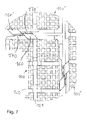
- the Fig. 7 shows the composite of several bottom plates 100, 100 'and 100' from the bottom 120 ago. As can be seen there, have the bottom plates in the substructure on a rib-shaped structure, which serves to stiffen the bottom 120.
- the structure consists of cruciform ribs 121, which allow to load the resting on a substrate base plate 100 with a high weight of eg 800 kg.
- the respective base plate may be concave, so that the plate bends only when loaded so that it then rests with all the ribs on the ground.
- the concave elevation and thus the deflection is less than 1.5 mm.
- the areas lying between the ribs 121 may be designed as smooth surfaces or, as shown here, have a specific structure.
- the spacing of the ribs 121 is selected so that the loading surface of the bottom plate 100 can not break even under punctiform loading (for example, by a person with 100 kg weight and stiletto heels).
- the underside 120 or rear side of the bottom plate is offset toward the middle or concave. Only the two outer rib rows form the total thickness of 38 mm, ie have the full extent of the plate height.
- the inner rows of ribs are lowered or set inwards. As a result, only the outer rows of ribs lie on the substrate, which leads to a smaller contact area and greatly reduces any unwanted absorption or "absorption" of moisture, especially in a moist surface.
- the bottom plate 100 can thereby rest well even with an uneven and slightly convex ground and thus be laid wobble-free.
- connection technique allows a very simple and quick assembly of floor panels to a fixed composite.
- the Fig. 8 shows by way of example in plan view, a first composite consisting of a plurality of square bottom plates 100 and 100 ', the same design, namely a groove-like top with transverse and longitudinal grooves have. By alternating rotation of the plates by 90 degrees, a checkerboard-like laying pattern is achieved.
- the Fig. 9 shows in plan view a second composite consisting of several square bottom plates 100 and 100 'with the same design of the top, the plates are laid in rows by a distance D offset, which corresponds to half the edge length.
- the Fig. 10 shows as a further embodiment, the construction of a T-shaped connection 166 by means of corresponding connection means 161a and 161b.
- This compound is under force (see. Fig. 4-6 ) at least self-clamping.
- Other alternative constructions of self-centering and / or self-clamping connections can be realized for example by trapezoidal, pyramidal, conical connecting elements.
- connection technique described here a very simple and quick laying of floor panels can be performed, creating a solid bond.
Abstract
Description
Die Erfindung betrifft ein Bodenelement nach dem Oberbegriff des Anspruchs 1. Insbesondere betrifft die Erfindung ein Bodenelement, das aus einem geformten Werkstoff besteht und als verlegbare Bodenplatte geformt ist, die mindestens vier Kanten aufweist.The invention relates to a floor element according to the preamble of claim 1. In particular, the invention relates to a floor element, which consists of a molded material and is shaped as a displaceable base plate having at least four edges.
Aus der
Das Verlegen solcher Bodenelemente erweist sich an Engstellen als eher schwierig, weil dort kaum ausreichend Platz zum horizontalen Zusammenfügen der Bodenelemente vorhanden ist. Auch erfordert eine evtl. später gewünschte (Teil-) Demontage des Verbundes, insbesondere an solchen Engstellen, ein gewisses handwerkliches Geschick.The laying of such floor elements proves to be bottlenecks rather difficult, because there is hardly enough space for horizontal assembly of the floor elements is present. Also requires a later desired (partial) disassembly of the composite, especially at such bottlenecks, a certain craftsmanship.
Bodenelemente mit vertikal sich zusammenfügenden Verbindungselementen sind an sich aus der
Allerdings hat sich bei den bekannten Bodenelementen gezeigt, dass sich bei einem im Freien verlegten Verbund, insbesondere bei einem großflächigen Verbund, schnell Regenwasser in größerer Menge ansammeln kann.However, it has been found in the known floor elements that can quickly accumulate rainwater in a larger amount in a composite laid outdoors, especially in a large-scale composite.
Aufgabe der Erfindung ist es daher, ein Bodenelement der eingangs genannten Art deutlich zu verbessern, so dass die genannten Nachteile vorteilhaft überwunden werden. Insbesondere sollen eine sehr einfache Montage und Demontage eines aus mehreren Bodenelementen zusammengesetzten Verbundes möglich sein, wobei der Verbund besonders gut im Freien verlegt und eingesetzt werden können soll.The object of the invention is therefore to significantly improve a floor element of the type mentioned, so that the mentioned disadvantages are overcome advantageously. In particular, a very simple assembly and disassembly of a compound composed of several soil elements composite should be possible, the composite should be particularly well laid outdoors and used.
Die Aufgabe wird gelöst durch ein Bodenelement mit den Merkmalen des Anspruchs 1.The object is achieved by a floor element with the features of claim 1.
Demnach wird ein Bodenelement vorgeschlagen, bei dem jede Kante eine seitliche Fläche mit mehreren daran angeordneten mehreren Verbindungselementen aufweist, die beim Zusammenfügen des Bodenelements mit einem benachbarten Bodenelement mit dessen Verbindungselementen durch eine vertikale Bewegung spielbehaftet in Eingriff kommen, wobei die Verbindungselemente sich von den seitlichen Flächen horizontal nach Außen hin erstrecken, so dass im zusammengefügten Zustand unter Ausnutzung des spielbehafteten Eingriffs sich ein Spalt zwischen den gegenüberliegenden Kanten der Bodenelemente ausbildet. Somit werden beim Zusammenfügen der Bodenelemente spielbehaftete Verbindungen hergestellt, die zwischen den jeweils benachbarten Bodenelementen einen Spalt lassen, durch den Wasser abfließen kann, das sich ansonsten auf der Oberfläche ansammeln würde.Accordingly, a floor element is proposed, in which each edge has a lateral surface with a plurality of connecting elements arranged thereon, which engage in a playful manner during assembly of the floor element with an adjacent floor element with its connecting elements by a vertical movement, wherein the connecting elements from the lateral surfaces extend horizontally to the outside, so that in the assembled state, taking advantage of the play-engaging engagement, a gap between the opposite edges of the bottom elements is formed. Thus, when joining the floor elements, playful connections are made which leave a gap between the respective adjacent floor elements, through which water can flow which otherwise would accumulate on the surface.
Durch diese Merkmalskombination wird ein neues und als Bodenplatte verlegbares Bodenelement geschaffen, das durch vertikale Bewegung sehr einfach direkt mit entsprechend ausgebildeten weiteren Bodenelementen zusammengefügt werden kann. Die Bodenelemente sind vorzugsweise quadratisch und können auch von Laien sehr leicht zu einem Verbund verlegt werden.This combination of features creates a new floor element that can be laid as a base plate, which can be very easily assembled directly with correspondingly designed further floor elements by vertical movement. The floor elements are preferably square and can also be laid by laymen very easily to a composite.
Durch die an jeder Kante jeweils vorgesehenen Verbindungselemente kann sehr einfach und schnell eine mechanisch stabile Verbindung zwischen jeweils zwei benachbarten Bodenelementen geschaffen werden, wobei immer ein Spalt verbleibt, der unter anderem zur Drainage von sich evtl. auf der Oberfläche ansammelndem Regenwasser und dergleichen dienen kann. Auch bewirkt der Spalt eine bessere Entlüftung der sich unterhalb der Unterseite ausbildenden Hohlräume. Zudem erleichtern der Spalt und die für eine vertikale Bewegung ausgerichtete Verbindungstechnik eine evtl. Demontage von zusammengefügten Bodenelementen.By each provided on each edge fasteners can be very easily and quickly created a mechanically stable connection between each two adjacent floor elements, always leaving a gap, among other things, for drainage of possibly on the surface accumulating rainwater and the like can serve. Also, the gap causes better ventilation of the cavities forming below the underside. In addition, the gap and the aligned for a vertical movement connection technology facilitate a possible dismantling of assembled floor elements.
Die Bodenelemente bzw. -platten können sowohl in gleichsinniger Ausrichtung wie auch abwechselnd in gegensinniger bzw. um 90 Grad gedrehter Ausrichtung verlegt werden. Damit ergeben sich sehr verschiedenartige Verlegemuster. Die funktionale wie auch optische Attraktivität wird insbesondere dadurch erhöht, dass die Oberseiten der Bodenelemente verschiedene Oberflächenstrukturen und/oder Farbgebungen und/oder Ausrichtung aufweisen können.The floor elements or panels can be laid both in the same direction as well as alternately in opposite directions or rotated by 90 degrees orientation. This results in very different laying patterns. The functional as well as optical attractiveness is increased in particular by the fact that the upper sides of the floor elements can have different surface structures and / or colors and / or orientation.
Besonders vorteilhafte Ausgestaltungen der Erfindung ergeben sich auch aus den Unteransprüchen:Particularly advantageous embodiments of the invention will become apparent from the dependent claims:
Vorzugsweise sind die Verbindungselemente als Elemente für formschlüssige, spielbehaftete Verbindungen ausgebildet, insbesondere für Schwalbenschanz-Verbindungen oder dergleichen ausgebildet. Dabei können die Verbindungselemente als Elemente für Verbindungen ausgebildet sein, die unter Einwirkung einer Kraft selbstklemmend und/oder selbstzentrierend sind. Insbesondere in diesem Zusammenhang ist es vorteilhaft, an den Kanten und/oder den seitlichen Flächen jeweils mindestens ein elastisches Element vorgesehen ist, das beim Zusammenfügen des Bodenelementes mit einem benachbarten Bodenelement und zur Ausnutzung des spielbehafteten Eingriffs der Verbindungselemente eine horizontal wirkende Druckkraft auf das benachbarte Bodenelement ausübt, so dass sich zwischen den jeweils gegenüberliegenden Kanten der Bodenelemente ein maximal möglicher Spalt ausbildet. Beispielsweise kann das elastische Element als ein an der Kante und/oder seitlichen Fläche vorgesehener elastischer Abschnitt oder als ein Federelement ausgebildet sein. Zudem kann das elastische Element einen Vorsprung aufweisen, der beim Zusammenfügen der Bodenelemente in einen an dem benachbarten Bodenelement angeordneten Vorsprung eingreift und die Bodenplatten gegen vertikales Verschieben sichert.Preferably, the connecting elements are designed as elements for positive, play-related connections, in particular for Schwalbenschanz connections or the like. In this case, the connecting elements can be designed as elements for connections, which are self-clamping and / or self-centering under the action of a force. In particular, in this context, it is advantageous to at least one elastic element is provided at the edges and / or the lateral surfaces, the horizontally acting pressure force on the adjacent floor element when joining the bottom element with an adjacent floor element and to exploit the play involving engagement of the connecting elements exerts, so that between the respective opposite edges of the floor elements a maximum possible gap forms. For example, the elastic element may be formed as an elastic portion provided on the edge and / or side surface or as a spring element. In addition, the elastic element may have a projection which engages in the assembly of the bottom elements in a arranged on the adjacent bottom element projection and secures the bottom plates against vertical displacement.
Auch können die Verbindungselemente an den seitlichen Flächen der Kanten so ausgebildet sein, dass die Verbindungselemente im zusammengefügten Zustand und zumindest unter Ausnutzung des spielbehafteten Eingriffs von Oben durch den sich ausbildenden Spalt zugänglich sind.Also, the connecting elements may be formed on the lateral surfaces of the edges so that the connecting elements are accessible in the assembled state and at least by utilizing the play-engaged engagement from above through the forming gap.
Auch sind vorzugsweise die zueinander beabstandeten Verbindungselemente in einem Abstand zueinander angeordnet bzw. versetzt, der einem rationalen Bruchteil der Kantenlänge, insbesondere der halben Kantenlänge entspricht. Damit kann ein durch den Abstand klar definiertes Rastermaß vorgegeben werden, welches dann sehr leicht beim Verlegen der Bodenelemente eingehalten werden kann. Somit können auch die jeweils zueinander benachbarten Bodenelemente in einem Versatzabstand, insbesondere in dem o.g. Abstand bzw. Rastermaß, zueinander verlegt und zusammengefügt werden. Durch eine solche versetzte Verlegung der Bodenelemente ergibt sich ein besonders ansprechender optischer Gesamteindruck.Also, preferably, the mutually spaced connecting elements are arranged at a distance from each other or offset, which corresponds to a rational fraction of the edge length, in particular half the edge length. Thus, a clearly defined by the distance pitch can be specified, which can then be easily adhered to when laying the floor elements. Thus, the mutually adjacent floor elements in an offset distance, in particular in the o.g. Distance or pitch, moved to each other and put together. Such an offset laying of the floor elements results in a particularly attractive overall visual impression.
Vorzugsweise nehmen die Verbindungselemente in ihrer Ausdehnung entlang der Kante bezogen auf die gesamte Kantenlänge nur einen Bruchteil von 30 oder weniger Prozent ein. Somit ist die sich ergebende Spaltlänge im ganzen sehr groß und beträgt mindestens 70 Prozent von der Gesamtlänge der jeweiligen Kante. Vorzugsweise nimmt der Spalt bzw. die Länge aller Spalte auf einer Kante mindestens 80 Prozent der Gesamtkantenlänge ein.Preferably, the fasteners occupy only a fraction of 30 or less percent in their extent along the edge with respect to the entire edge length. Thus, the resulting gap length is very high overall large and is at least 70 percent of the total length of each edge. Preferably, the gap or the length of all gaps on an edge occupies at least 80 percent of the total edge length.
Das Bodenelement kann vorteilhafter Weise auch eine Oberseite haben, welche zur Mitte hin ballig bzw. konvex ausgeformt ist. Dadurch wird insbesondere für das Verlegen in Außenbereichen eine automatische Ablaufwirkung für Regenwasser und dergleichen geschaffen. Unabhängig davon oder auch im Zusammenhang damit kann die Unterseite des Bodenelementes zur Mitte hin abgesetzt bzw. konkav ausgeformt sein. Dadurch wird sichergestellt, dass das als Bodenplatte gestaltete Bodenelement auch auf einem unebenen Untergrund sicher und wackelfrei aufliegt.The bottom element may advantageously also have an upper side, which is formed convex toward the center or convex. As a result, an automatic drainage action for rainwater and the like is created especially for laying in outdoor areas. Regardless of or in connection therewith, the underside of the bottom element may be offset towards the middle or concave. This ensures that the designed as a bottom plate floor element rests safely and wobble on an uneven surface.
Die Erfindung wird nun im Detail anhand von mehreren Ausführungsbeispielen beschrieben, wobei auf die folgenden Zeichnungen Bezug genommen wird:
- Fig. 1
- zeigt in dreidimensionaler Darstellung ein Bodenelement mit seitlich angeordneten Verbindungselementen;
- Fig. 2
- zeigt das Bodenelement in einer Draufsicht;
- Fig. 3
- zeigt in einer Seitenansicht das Bodenelement mit den daran angeordneten Verbindungselementen;
- Fig. 4
- zeigt in einer Draufsicht und im Detail eine zwischen zwei benachbarten Bodenelementen hergestellte Verbindung in Form einer Schwalbenschanz-Verbindung;
- Fig. 5
- zeigt in einer Querschnittsansicht die Schwalbenschwanz-Verbindung und ein darauf einwirkendes elastisches Element;
- Fig. 6
- zeigt im Detail die Schwalbenschwanz-Verbindung und das darauf einwirkende elastische Element;
- Fig. 7
- zeigt in einem Ausschnitt die Unterseiten von mehreren zusammengefügten Bodenelementen und die jeweils dazwischen hergestellten Verbindungen;
- Fig. 8
- zeigt in einer Draufsicht einen Verbund aus mehreren zusammengefügten Bodenelementen;
- Fig. 9
- zeigt in einer Draufsicht einen weiteren Verbund aus mehreren zusammengefügten Bodenelementen; und
- Fig. 10
- zeigt alternativ zu den Darstellungen nach
Fig. 4 undFig. 7 eine weitere Verbindung zwischen benachbarten Bodenelementen.
- Fig. 1
- shows a three-dimensional view of a bottom element with laterally arranged connecting elements;
- Fig. 2
- shows the bottom element in a plan view;
- Fig. 3
- shows in a side view of the bottom element with the connecting elements arranged thereon;
- Fig. 4
- shows in a plan view and in detail a connection made between two adjacent floor elements in the form of a Dovetail connection;
- Fig. 5
- shows in a cross-sectional view of the dovetail connection and an elastic element acting thereon;
- Fig. 6
- shows in detail the dovetail connection and the elastic element acting thereon;
- Fig. 7
- shows in a section the lower sides of a plurality of assembled floor elements and the connections made therebetween;
- Fig. 8
- shows in a plan view of a composite of several assembled floor elements;
- Fig. 9
- shows in a plan view another composite of a plurality of assembled floor elements; and
- Fig. 10
- shows as an alternative to the illustrations after
Fig. 4 andFig. 7 another connection between adjacent floor elements.
Die
Die Bodenplatte 100 hat eine geschlossene Fläche von z.B. 40 cm X 40 cm, die begangen wird und auch direkt der Witterung ausgesetzt ist. Die quadratische Bodenplatte 100 weist vier Kanten 130 mit jeweils einer Kantenlänge L von 40 cm auf. Die Oberseite 110 bzw. die Begehfläche ist um ca. 1-2 mm ballig (konvex) ausgeführt damit z.B. Regenwasser nicht auf der Fläche stehen bleiben kann, die Oberfläche somit schneller abtrocknen kann und sich keine Pfützen bilden können. Durch die Materialwahl hat das Bodenelement 100, insbesondere seine Oberseite 110, eine gewollt holzähnliche Optik. Durch eine tiefe Rillenstruktur auf der Fläche ergibt sich eine verbesserte Rutschfestigkeit und Verschmutzungs-Unempfindlichkeit, da der Schmutz in den Rillentälern weniger auffällt. Die Rillenberge können durch Aufrauen mit Stahlbürsten, Schleiflamellen o.ä. noch holzähnlicher und rutschfester gestaltet werden.The
Die Bodenplatte 100 ist beispielsweise 38 mm hoch und weist an jeder ihrer vier Kanten 130 seitliche Flächen 131 auf, an denen mehrere Verbindungselemente 160 angeordnet sind. Diese sind zumindest paarweise äquidistant in einem Abstand D angeordnet, welcher vorzugsweise der halben Länge L einer Kante 130 entspricht, hier also 20 cm beträgt. Damit können beim Verlegen die Bodenplatten 100 in einer Linie oder auf Lücke mit einem Versatz von einer halben Plattenbreite verlegt werden (siehe auch
Die Gestaltung der Verbindungselemente 160 ist bei dem hier gezeigten Beispiel für eine schwalbenschwanz-artige Verbindung ausgelegt und wird nachfolgend im Detail anhand der
Zunächst wird hier auf die
Dies wird in der
Die Verbindungselemente 160 und 160' stehen von den seitlichen Flächen soweit ab, dass beim Zusammenfügen noch ein vorgebbarer Spalt SP zwischen den gegenüberliegenden Kanten 130 und 130' der benachbarten Bodenplatten verbleibt. Dadurch besteht zwischen den Bodenplatten innerhalb eines Verbundes jeweils ein ausreichend großer Abstand bzw. Spalt SP, der zur Drainage und/oder Belüftung dienen kann und zudem es ermöglicht, dass einzelne Platten sehr leicht auch demontiert und ausgetauscht werden können.The connecting
Da die Verbindung 165 durch einen spielbehafteten Eingriff der Verbindungselemente 160 und 160' entsteht und somit die Verbindung und auch der sich jeweils ergebende Spalt SP nicht fixiert sind, können flexible Elemente vorgesehen werden, die auf die Verbindung eine Kraft F ausüben, um die Verbindung in eine selbstklemmende und/oder selbstzentrierende Position zu bringen, d.h. hier in die Position des maximal möglichen Abstands bzw. Spaltes SP.Since the
Die
In der
Der sich insbesondere wegen der Andrückkraft F ergebende, definierte Abstand SP zwischen den Bodenplatten ist auch vorteilhaft hinsichtlich einer Kompensation für gewisse Toleranzabweichungen, die bei der Herstellung der Bodenplatten (oder auch bei Alterung) auftreten können. Somit wird durch die hier vorgeschlagene Konstruktion immer ein optimales Verlege-Ergebnis erzielt. Insbesondere können die Bodenplatten sich im Verbund aufgrund von Wärmeeinwirkung und/oder Feuchtigkeitsaufnahme ausdehnen, ohne dass dies Auswirkungen, insbesondere Spannungen, auf die verlegte Fläche hat.The resulting in particular because of the pressing force F, defined distance SP between the bottom plates is also advantageous in terms of compensation for certain tolerance deviations that can occur during the manufacture of the bottom plates (or even with aging). Thus, the construction proposed here always achieves an optimal laying result. In particular, the floor panels may expand in the composite due to heat and / or moisture absorption, without this having any effects, in particular stresses, on the laid surface.
Die
In der
Die
Die
Die
Durch die hier beschriebene Verbindungstechnik kann ein sehr einfaches und schnelles Verlegen von Bodenplatten durchgeführt werden, wobei ein fester Verbund entsteht.By the connection technique described here, a very simple and quick laying of floor panels can be performed, creating a solid bond.
- 100100
- Bodenelement, hier als Bodenplatte ausgebildetFloor element, designed here as a base plate
- 110110
- Oberseite des BodenelementsTop of the floor element
- 120120
- Unterseite des Bodenelements mit StützstrukturBottom of the floor element with support structure
- 121121
- Verstrebungen der StützstrukturStruts of the support structure
- 130130
- Kanten des jeweiligen BodenelementesEdges of the respective floor element
- 131131
- seitliche Flächen an den Kantenlateral surfaces at the edges
- LL
- Kantenlängeedge length
- DD
- Abstand bzw. Versatz (Rastermaß) zwischen den VerbindungselementenDistance or offset (pitch) between the connecting elements
- SPSP
- Spalt zwischen den BodenelementenGap between the floor elements
- 160160
- Verbindungselemente (keilförmig)Connecting elements (wedge-shaped)
- 165165
- Schwalbenschwanz-Verbindung (unter Krafteinwirkung selbstklemmend und selbstzentrierend)Dovetail connection (force self-locking and self-centering)
- 161a/b161a / b
- Verbindungselemente (T-förmig)Connecting elements (T-shaped)
- 166166
- T-Verbindung (unter Krafteinwirkung selbstklemmend)T-connection (self-clamping under force)
- 162162
-
Vorsprung am Verbindungselement 160Projection on the connecting
element 160 - 170170
- elastisches Element (Andrückelement)elastic element (pressure element)
- 172172
- Vorsprung am elastischen ElementProjection on the elastic element
Claims (11)
jede Kante (130) des Bodenelementes (100) eine seitliche Fläche (131) mit mehreren daran angeordneten Verbindungselementen (160) aufweist, die beim Zusammenfügen des Bodenelements (100) mit einem benachbarten Bodenelement (100') mit dessen Verbindungselementen (160') durch eine vertikale Bewegung spielbehaftet in Eingriff kommen, wobei die Verbindungselemente (160, 160') sich von den seitlichen Flächen (131) horizontal nach Außen hin erstrecken, so dass im zusammengefügten Zustand unter Ausnutzung des spielbehafteten Eingriffs sich ein Spalt (SP) zwischen den gegenüberliegenden Kanten (130) der Bodenelemente (100, 100') ausbildet.Floor element (100), which consists of a molded material and having a top surface (110) with a predeterminable surface and a bottom (120) with a support structure (121), wherein the bottom element (100) is formed as a movable bottom plate, the at least four edges (130), characterized in that
each edge (130) of the bottom element (100) has a lateral surface (131) with a plurality of connecting elements (160) arranged thereon, which when joining the bottom element (100) to an adjacent bottom element (100 ') with its connecting elements (160') a vertical movement playfully engaged, wherein the connecting elements (160, 160 ') extending from the lateral surfaces (131) horizontally to the outside, so that in the assembled state by utilizing the play-engaged engagement, a gap (SP) between the opposite Edges (130) of the floor elements (100, 100 ') is formed.
Applications Claiming Priority (1)
| Application Number | Priority Date | Filing Date | Title |
|---|---|---|---|
| DE102008062986A DE102008062986A1 (en) | 2008-12-23 | 2008-12-23 | Floor element with connecting elements |
Publications (2)
| Publication Number | Publication Date |
|---|---|
| EP2206853A2 true EP2206853A2 (en) | 2010-07-14 |
| EP2206853A3 EP2206853A3 (en) | 2012-03-21 |
Family
ID=41820497
Family Applications (1)
| Application Number | Title | Priority Date | Filing Date |
|---|---|---|---|
| EP09179807A Withdrawn EP2206853A3 (en) | 2008-12-23 | 2009-12-18 | Floor element with connection elements |
Country Status (2)
| Country | Link |
|---|---|
| EP (1) | EP2206853A3 (en) |
| DE (1) | DE102008062986A1 (en) |
Cited By (1)
| Publication number | Priority date | Publication date | Assignee | Title |
|---|---|---|---|---|
| US8806832B2 (en) | 2011-03-18 | 2014-08-19 | Inotec Global Limited | Vertical joint system and associated surface covering system |
Citations (5)
| Publication number | Priority date | Publication date | Assignee | Title |
|---|---|---|---|---|
| US4054987A (en) | 1976-02-26 | 1977-10-25 | Mateflex/Mele Corporation | Construction method |
| GB1600823A (en) | 1977-02-02 | 1981-10-21 | Kraayenhof Design Bv | Flooring element of plastics material |
| US4584221A (en) | 1984-07-19 | 1986-04-22 | Sportforderung Peter Kung Ag | Floor covering assembly |
| AT413840B (en) | 2003-07-07 | 2006-06-15 | Poschacher Natursteinwerke Gmb | PLATE FOR LAYING ON FLOORS, WALLS, CEILINGS, FAÇADES OR DGL. |
| DE102006055715A1 (en) | 2006-11-23 | 2008-05-29 | Werzalit Ag + Co. Kg | Base element e.g. quadratic base plate, for use in composite, has two fastening elements that are provided with projecting detents, which engage in counter-detent positions during combination of base element with further base elements |
Family Cites Families (3)
| Publication number | Priority date | Publication date | Assignee | Title |
|---|---|---|---|---|
| DE3470337D1 (en) * | 1984-10-05 | 1988-05-11 | Daniel Rudler | Device with assembly panels, especially for the construction of a ground covering, a floor or a ceiling |
| US4930286A (en) * | 1988-03-14 | 1990-06-05 | Daniel Kotler | Modular sports tile with lateral absorption |
| US20080127593A1 (en) * | 2006-07-14 | 2008-06-05 | Janesky Lawrence M | Moisture-resistant cover floor system for concrete floors |
-
2008
- 2008-12-23 DE DE102008062986A patent/DE102008062986A1/en not_active Withdrawn
-
2009
- 2009-12-18 EP EP09179807A patent/EP2206853A3/en not_active Withdrawn
Patent Citations (5)
| Publication number | Priority date | Publication date | Assignee | Title |
|---|---|---|---|---|
| US4054987A (en) | 1976-02-26 | 1977-10-25 | Mateflex/Mele Corporation | Construction method |
| GB1600823A (en) | 1977-02-02 | 1981-10-21 | Kraayenhof Design Bv | Flooring element of plastics material |
| US4584221A (en) | 1984-07-19 | 1986-04-22 | Sportforderung Peter Kung Ag | Floor covering assembly |
| AT413840B (en) | 2003-07-07 | 2006-06-15 | Poschacher Natursteinwerke Gmb | PLATE FOR LAYING ON FLOORS, WALLS, CEILINGS, FAÇADES OR DGL. |
| DE102006055715A1 (en) | 2006-11-23 | 2008-05-29 | Werzalit Ag + Co. Kg | Base element e.g. quadratic base plate, for use in composite, has two fastening elements that are provided with projecting detents, which engage in counter-detent positions during combination of base element with further base elements |
Cited By (3)
| Publication number | Priority date | Publication date | Assignee | Title |
|---|---|---|---|---|
| US8806832B2 (en) | 2011-03-18 | 2014-08-19 | Inotec Global Limited | Vertical joint system and associated surface covering system |
| US9103126B2 (en) | 2011-03-18 | 2015-08-11 | Inotec Global Limited | Vertical joint system and associated surface covering system |
| US10000935B2 (en) | 2011-03-18 | 2018-06-19 | Inotec Global Limited | Vertical joint system and associated surface covering system |
Also Published As
| Publication number | Publication date |
|---|---|
| EP2206853A3 (en) | 2012-03-21 |
| DE102008062986A1 (en) | 2010-07-01 |
Similar Documents
| Publication | Publication Date | Title |
|---|---|---|
| DE69814867T2 (en) | METHOD FOR ATTACHING A PANEL CONSISTING OF BOARDS, LATCHES OR SIMILAR AND A PANEL MADE THEREOF | |
| DE102006057491A1 (en) | Panel and flooring | |
| DE102011056494A1 (en) | Set of panels with clip | |
| DE202007000310U1 (en) | Panel for floor covering has vertical locking element with complementary hook elements that are configured so that connected panels can be unlocked from their hooked and vertically locked state | |
| DE102007049792A1 (en) | connection | |
| DE202005002204U1 (en) | Laying system for creating a wall, floor or ceiling covering | |
| DE10230818B3 (en) | Floor panel and method for laying a floor panel | |
| DE102007002590A1 (en) | Panel and flooring | |
| EP2915934A1 (en) | Set consisting of panels with a locking element | |
| EP1367194A2 (en) | Flooring panel and method of laying such a panel | |
| EP1524385B1 (en) | Extruded panel, in particular for flooring | |
| EP1930524A2 (en) | Flooring plate and covering created therewith | |
| EP2754773B1 (en) | Substructure for a floor covering | |
| EP0676169A1 (en) | Grids or mats; in particular floor mats and/or scrapers | |
| DE2803892A1 (en) | FLOORING PANEL AND FLOOR COVERING PRODUCED WITH IT | |
| AT13863U1 (en) | Arrangement for forming a floor covering | |
| DE202005018351U1 (en) | Floor mat material has cover plate arranged and fastened on top surface of pack frame, such that pack frame is made of plastics and has anchors inserted into recesses formed on cover plate | |
| EP3372749B1 (en) | Floorboard system | |
| EP1197611A1 (en) | Floor plate for dismantable floor | |
| EP2206853A2 (en) | Floor element with connection elements | |
| DE202009001671U1 (en) | profile element | |
| EP2995747B1 (en) | Mechanical connection for panels and method of mounting a locking tongue in a panel | |
| DE202008005295U1 (en) | connection | |
| DE2238228A1 (en) | FLOOR STRUCTURE, IN PARTICULAR FOR Cattle barn | |
| EP1353023A2 (en) | Floor covering section with locking device |
Legal Events
| Date | Code | Title | Description |
|---|---|---|---|
| PUAI | Public reference made under article 153(3) epc to a published international application that has entered the european phase |
Free format text: ORIGINAL CODE: 0009012 |
|
| AK | Designated contracting states |
Kind code of ref document: A2 Designated state(s): AT BE BG CH CY CZ DE DK EE ES FI FR GB GR HR HU IE IS IT LI LT LU LV MC MK MT NL NO PL PT RO SE SI SK SM TR |
|
| AX | Request for extension of the european patent |
Extension state: AL BA RS |
|
| PUAL | Search report despatched |
Free format text: ORIGINAL CODE: 0009013 |
|
| AK | Designated contracting states |
Kind code of ref document: A3 Designated state(s): AT BE BG CH CY CZ DE DK EE ES FI FR GB GR HR HU IE IS IT LI LT LU LV MC MK MT NL NO PL PT RO SE SI SK SM TR |
|
| AX | Request for extension of the european patent |
Extension state: AL BA RS |
|
| RIC1 | Information provided on ipc code assigned before grant |
Ipc: E04F 15/10 20060101AFI20120210BHEP |
|
| 17P | Request for examination filed |
Effective date: 20120921 |
|
| RBV | Designated contracting states (corrected) |
Designated state(s): AT BE BG CH CY CZ DE DK EE ES FI FR GB GR HR HU IE IS IT LI LT LU LV MC MK MT NL NO PL PT RO SE SI SK SM TR |
|
| STAA | Information on the status of an ep patent application or granted ep patent |
Free format text: STATUS: THE APPLICATION IS DEEMED TO BE WITHDRAWN |
|
| 18D | Application deemed to be withdrawn |
Effective date: 20170701 |