EP2210303B1 - Fuel cell systems including space-saving fluid plenum and related methods - Google Patents
Fuel cell systems including space-saving fluid plenum and related methods Download PDFInfo
- Publication number
- EP2210303B1 EP2210303B1 EP08800400.7A EP08800400A EP2210303B1 EP 2210303 B1 EP2210303 B1 EP 2210303B1 EP 08800400 A EP08800400 A EP 08800400A EP 2210303 B1 EP2210303 B1 EP 2210303B1
- Authority
- EP
- European Patent Office
- Prior art keywords
- fuel cell
- fluid
- cell layer
- layer
- enclosed region
- Prior art date
- Legal status (The legal status is an assumption and is not a legal conclusion. Google has not performed a legal analysis and makes no representation as to the accuracy of the status listed.)
- Not-in-force
Links
Images
Classifications
-
- H—ELECTRICITY
- H01—ELECTRIC ELEMENTS
- H01M—PROCESSES OR MEANS, e.g. BATTERIES, FOR THE DIRECT CONVERSION OF CHEMICAL ENERGY INTO ELECTRICAL ENERGY
- H01M8/00—Fuel cells; Manufacture thereof
- H01M8/24—Grouping of fuel cells, e.g. stacking of fuel cells
- H01M8/2465—Details of groupings of fuel cells
- H01M8/2484—Details of groupings of fuel cells characterised by external manifolds
- H01M8/2485—Arrangements for sealing external manifolds; Arrangements for mounting external manifolds around a stack
-
- H—ELECTRICITY
- H01—ELECTRIC ELEMENTS
- H01M—PROCESSES OR MEANS, e.g. BATTERIES, FOR THE DIRECT CONVERSION OF CHEMICAL ENERGY INTO ELECTRICAL ENERGY
- H01M8/00—Fuel cells; Manufacture thereof
- H01M8/24—Grouping of fuel cells, e.g. stacking of fuel cells
- H01M8/241—Grouping of fuel cells, e.g. stacking of fuel cells with solid or matrix-supported electrolytes
- H01M8/2418—Grouping by arranging unit cells in a plane
-
- H—ELECTRICITY
- H01—ELECTRIC ELEMENTS
- H01M—PROCESSES OR MEANS, e.g. BATTERIES, FOR THE DIRECT CONVERSION OF CHEMICAL ENERGY INTO ELECTRICAL ENERGY
- H01M8/00—Fuel cells; Manufacture thereof
- H01M8/02—Details
- H01M8/0297—Arrangements for joining electrodes, reservoir layers, heat exchange units or bipolar separators to each other
-
- H—ELECTRICITY
- H01—ELECTRIC ELEMENTS
- H01M—PROCESSES OR MEANS, e.g. BATTERIES, FOR THE DIRECT CONVERSION OF CHEMICAL ENERGY INTO ELECTRICAL ENERGY
- H01M8/00—Fuel cells; Manufacture thereof
- H01M8/04—Auxiliary arrangements, e.g. for control of pressure or for circulation of fluids
- H01M8/04082—Arrangements for control of reactant parameters, e.g. pressure or concentration
- H01M8/04201—Reactant storage and supply, e.g. means for feeding, pipes
-
- H—ELECTRICITY
- H01—ELECTRIC ELEMENTS
- H01M—PROCESSES OR MEANS, e.g. BATTERIES, FOR THE DIRECT CONVERSION OF CHEMICAL ENERGY INTO ELECTRICAL ENERGY
- H01M8/00—Fuel cells; Manufacture thereof
- H01M8/24—Grouping of fuel cells, e.g. stacking of fuel cells
- H01M8/2465—Details of groupings of fuel cells
- H01M8/2484—Details of groupings of fuel cells characterised by external manifolds
-
- H—ELECTRICITY
- H01—ELECTRIC ELEMENTS
- H01M—PROCESSES OR MEANS, e.g. BATTERIES, FOR THE DIRECT CONVERSION OF CHEMICAL ENERGY INTO ELECTRICAL ENERGY
- H01M2250/00—Fuel cells for particular applications; Specific features of fuel cell system
- H01M2250/30—Fuel cells in portable systems, e.g. mobile phone, laptop
-
- H—ELECTRICITY
- H01—ELECTRIC ELEMENTS
- H01M—PROCESSES OR MEANS, e.g. BATTERIES, FOR THE DIRECT CONVERSION OF CHEMICAL ENERGY INTO ELECTRICAL ENERGY
- H01M8/00—Fuel cells; Manufacture thereof
- H01M8/04—Auxiliary arrangements, e.g. for control of pressure or for circulation of fluids
- H01M8/04082—Arrangements for control of reactant parameters, e.g. pressure or concentration
- H01M8/04186—Arrangements for control of reactant parameters, e.g. pressure or concentration of liquid-charged or electrolyte-charged reactants
-
- Y—GENERAL TAGGING OF NEW TECHNOLOGICAL DEVELOPMENTS; GENERAL TAGGING OF CROSS-SECTIONAL TECHNOLOGIES SPANNING OVER SEVERAL SECTIONS OF THE IPC; TECHNICAL SUBJECTS COVERED BY FORMER USPC CROSS-REFERENCE ART COLLECTIONS [XRACs] AND DIGESTS
- Y02—TECHNOLOGIES OR APPLICATIONS FOR MITIGATION OR ADAPTATION AGAINST CLIMATE CHANGE
- Y02B—CLIMATE CHANGE MITIGATION TECHNOLOGIES RELATED TO BUILDINGS, e.g. HOUSING, HOUSE APPLIANCES OR RELATED END-USER APPLICATIONS
- Y02B90/00—Enabling technologies or technologies with a potential or indirect contribution to GHG emissions mitigation
- Y02B90/10—Applications of fuel cells in buildings
-
- Y—GENERAL TAGGING OF NEW TECHNOLOGICAL DEVELOPMENTS; GENERAL TAGGING OF CROSS-SECTIONAL TECHNOLOGIES SPANNING OVER SEVERAL SECTIONS OF THE IPC; TECHNICAL SUBJECTS COVERED BY FORMER USPC CROSS-REFERENCE ART COLLECTIONS [XRACs] AND DIGESTS
- Y02—TECHNOLOGIES OR APPLICATIONS FOR MITIGATION OR ADAPTATION AGAINST CLIMATE CHANGE
- Y02E—REDUCTION OF GREENHOUSE GAS [GHG] EMISSIONS, RELATED TO ENERGY GENERATION, TRANSMISSION OR DISTRIBUTION
- Y02E60/00—Enabling technologies; Technologies with a potential or indirect contribution to GHG emissions mitigation
- Y02E60/30—Hydrogen technology
- Y02E60/50—Fuel cells
Definitions
- Portable electronic devices are trending to become smaller in size while increasing the demand for performance.
- the demands on the associated power supply become greater.
- the power supply may need to occupy less volume or a smaller footprint to accommodate the addition of technology to the component or the decrease in overall component size.
- the additional technology may require that the power supply last for longer periods of time or that power be delivered at uniform rates for steady electronic component performance.
- a fuel cell system may include one or multiple fuel cell layers, each layer comprising anodes, cathodes, and an electrolyte membrane interposed between the anodes and cathodes.
- a fuel cell system which includes such a layer typically includes a means for supplying air to the cathode or cathodes and a means for supply of fuel or other reactant fluid to the anode or anodes at an acceptable pressure level.
- fluid supply components need to continue to supply fuel from a fluid supply to the anode or anodes of the fuel cell. This supply of fuel should be performed at an acceptable pressure level and delivery rate, without occupying an overall significant volume of the fuel cell system, and without compromising the performance of the fuel cell system.
- US2007/090786 discloses a flexible fuel cell layer of the prior art.
- Embodiments of the present invention relate to a fuel cell system.
- the system includes a fluid manifold having a first and a second side, at least one manifold outlet in the first side, and a manifold inlet fluidly coupled to the manifold outlet via a fluid directing recess located within the fluid manifold, a fuel cell layer including at least one fuel cell wherein at least a portion of the fuel cell layer is bonded to the first side of the fluid manifold such that the fuel cell layer is substantially adjacent to the first side of fluid manifold and an enclosed region formed by the bonded fuel cell layer and the fluid manifold.
- the one or more portions of the fuel cell layer or fluid manifold are adapted to deform away from each other upon pressurization of the enclosed region by fluid introduced through the manifold outlet.
- Embodiments also relate to a method of operating a fuel cell system including introducing a fluid into an enclosed region of a fuel cell system via a fluid manifold sufficient to increase the pressure within the enclosed region and imparting a stress to one or more portions of the fuel cell layer or the fluid manifold sufficient to transform the enclosed region into a fluid plenum.
- Embodiments relate to a flexible fuel cell layer.
- the layer includes two or more fuel cells substantially integrated within a two-dimensional layer, a substrate coupled to the layer forming an enclosed region between the substrate and layer.
- the layer can be positioned in a planar or non-planar configuration and the layer is configured such that it is operable when self-supported.
- Portable electronic devices such as mobile phones, laptop computers, computer accessories, displays, personal audio or video players, medical devices, televisions, transmitters, receivers, lighting devices including outdoor lighting or flashlights, electronic toys, power tools or any device conventionally used with batteries, are trending to become smaller in size while increasing the demand for performance.
- fuel cell systems may need to occupy only a small volume of the overall electrical device volume, while still providing adequate distribution control of fuel or other reactant fluid to the fuel cell. Even so, current fuel cell systems are either too large to be used in the electrical devices or fail to provide the necessary fluid distribution control to allow the devices to function properly.
- current portable fuel cell-powered electronic devices are typically designed around the space required by the fuel cells and associated fuel storage, rather than the fuel cell system being designed to fit within the electronic device. Such order of design often results in undesirably bulky devices.
- the present inventors have recognized that, among other things, a fluid supply system with reduced volumetric requirements, but which is able to supply fuel or other reactant fluid to the anode or anodes of a fuel cell at an acceptable pressure level and in a uniform manner is needed.
- the present inventors have further recognized that a deformable enclosed region located between fluid control elements and the fuel cell allows fuel to be supplied to the anode or anodes at an acceptable pressure level and delivery rate, while allowing for a more compact fuel cell system.
- a fuel cell system in one example, includes a fluid manifold having first and second sides, at least one manifold outlet in the first side, and a manifold inlet fluidly coupled to the manifold outlet via a fluid directing recess located within the fluid manifold, a fuel cell layer including at least one fuel cell wherein a portion of the fuel cell layer is bonded to the first side of the fluid manifold (such as peripherally bonded), and an enclosed region formed by the bonded fuel cell layer and the fluid manifold.
- the enclosed region may be essentially volumeless with the fuel cell layer adjacent to the first major side of a substrate, such as a fluid manifold.
- a substrate such as a fluid manifold.
- the fuel cell layer, the fluid manifold, or both may be flexible in whole or in part and thus may be deformed under application of modest pressure, or may include inherent material properties, such as elasticity, which enable the components to adapt in response to an imparted stress.
- one or more portions of the fuel cell layer or the fluid manifold may deform away from each other when the enclosed region is pressurized by fluid (e.g. fuel) from the manifold outlet. This transforms the enclosed region from being substantially volumeless into a region with sufficient volume to serve as a fluid distribution plenum for the fuel cell layer.
- a stress imparted by the introduction of a pressurized fluid may result in the adaptation or modification of the fuel cell layer, a portion thereof, or the fluid manifold sufficient to transform the enclosed region, either chemically or physically, into a fluid plenum, such as a fuel plenum.
- a fluid plenum such as a fuel plenum.
- the plenum may collapse in whole or in part depending on how elastic the components are.
- the enclosed region upon reapplication of fluid pressure, the enclosed region once again may inflate or otherwise transform sufficiently to serve as a fluid plenum.
- the described fuel cell systems and methods therefore have reduced volumetric requirements.
- the fuel cell system may additionally employ external supports or fixtures to support the fluid plenum formed between the fuel cell layer and fluid manifold, external supports or fixtures are not necessary.
- the flexible fuel cell layer and/or flexible fluid manifold are thus "self-supported" components, that is no external supports or fixturing are required for their function.
- Such "self-supported" flexible fuel cell layers are useful not only in the fabrication of systems in which there is initially no fluid plenum but they can be useful in other systems as well.
- a distance between the fluid manifold outlet side and the fuel cell layer at a non-pressurized enclosed region state is approximately equal to a cross-sectional thickness of a bond member.
- the fluid manifold and the fuel cell layer have a combined cross-sectional thickness of about 5 mm or less, about 1 mm or less, or about 0.6 mm or less at a non-pressurized enclosed region state.
- the present systems and methods provide for fuel cell systems occupying less volume or a smaller footprint of an electronic component or device into which they are installed, while still meeting the power demands of the component or device.
- the present fuel cell systems and methods include a space-saving fluid plenum transformable from a substantially volumeless enclosed region and in this way, allows for the creation of smaller, more compact fuel cell systems configurable to fit within an existing electronic device.
- the enclosed region may be located between a substrate (i.e., fluid manifold) and at least one fuel cell layer.
- the enclosed region may be formed by a peripheral-type of coupling between an outlet side of the fluid manifold and the fuel cell layer via suitable bonding means (e.g. a bond member).
- the enclosed region transforms into a fluid plenum when a fluid exiting the fluid manifold pressurizes the enclosed region causing one or more portions of the fuel cell layer and/or the fluid manifold to deform away from each other.
- a distance between the outlet side of the fluid manifold and the fuel cell layer at a non-pressurized enclosed region state is approximately equal to a cross-sectional thickness of a bond member.
- the cross-sectional thickness of the bond member is about 0.05 mm or less.
- the cross-sectional thickness of the bond member is about 1 mm or less, or about 0.2 mm or less.
- the space-saving fluid plenum can be used in conjunction with other fuel cell components, such as a fluid reservoir, a fluid pressure regulator device(s), a fluid manifold, a bond member, a fuel cell, and an optional external support structure, to create a compact fuel cell system.
- other fuel cell components such as a fluid reservoir, a fluid pressure regulator device(s), a fluid manifold, a bond member, a fuel cell, and an optional external support structure, to create a compact fuel cell system.
- flexible electrochemical layer refers to include an electrochemical layer that is flexible in whole or in part, so-as-to embrace, for example, an electrochemical layer having one or more rigid components integrated with one or more flexible components.
- a “flexible fuel cell layer” refers to a layer comprising one or more fuel cells integrated into the layer.
- flexible two-dimensional (2-D) fuel cell array refers to a flexible sheet which is thin in one dimension and which supports a number of fuel cells.
- a flexible two-dimensional fuel cell array may be an example of a flexible fuel cell layer.
- the fuel cells have active areas of one type (e.g. cathodes) that are accessible from one face of the sheet and active areas of another type (e.g. anodes) that are accessible from an opposed face of the sheet.
- the active areas may be disposed to lie within areas on their respective faces of the sheet (e.g. it is not mandatory that the entire sheet be covered with active areas, however, the performance of a fuel cell may be increased by increasing its active area.
- self-supported refers to an electrochemical cell layer if, when coupled to a substrate, no external fixturing is required to create and/or maintain the integrity of a fuel plenum when in use.
- adjacent when used in the context of the fuel cell layer being adjacent to the fluid manifold, refers to a fuel cell layer is close enough proximity to the fluid manifold such that the enclosed region is too small to effectively function as a fluid distribution plenum.
- bonding member refers to an implicit or explicit component that facilitates the coupling of two objects.
- an implicit bonding member may include an adhesive or weld.
- An explicit bonding member may include a mechanical fastener, for example.
- operable refers to an electrochemical cell layer or individual electrochemical cell capable of producing an electrical current or voltage.
- a fuel cell layer may be in an operable position and capable of producing electricity without further manipulation in position or configuration.
- substrate refers to a component coupled to an electrochemical cell layer, sufficient to create an enclosed space.
- a substrate may include, among other things, a fluid manifold, a fuel cell system structural member, fluidic control components, fluid reservoir, a portion of an electronic device or a combination thereof.
- Fluidic control components may include pressure regulator devices, such as an array of regulators, for example.
- deform or “deformation” refers to in general, the behaviour of a material, component, structure, or composite layer in response to an imparted stress.
- a deformation may be an intended result, or it may be an unintended side effect.
- a deformation may be of a large enough magnitude to be clearly visible to the naked eye (e.g on the order of millimeters), or may be small enough that it can only be detected with the aide of a microscope (e.g. on the order of micrometers or nanometers).
- a deformation may comprise the 'flexing' or 'bending' of a component, or may alternately comprise compression or other such change in shape of a component.
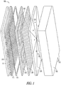
- FIG. 1 illustrates an exploded view of a fuel cell system 100 comprising, but not limited to, a fluid reservoir 102, an optional fluid pressure regulator assembly 104 including multiple fluid pressure regulator devices 126, a manifold sealing layer 106, a manifold conduit layer 108, a bond member 110, a fuel cell layer 112, and an external support structure 114.
- the fluid reservoir 102 provides fuel or other reactant fluid for the fuel cell system 100 and can be charged or refueled via a charge port 116.
- the fluid reservoir 102 can comprise a cellular fuel tank, such as is discussed in commonly-owned Zimmermann, U.S. Patent Application Serial No.
- a fluid manifold which may optionally include one or more of the fluid pressure regulator assembly 104, the manifold sealing layer 106, and the manifold conduit layer 108 provides for the distribution, regulation, and transfer of fuel from the fluid reservoir 102 to the fuel cell layer 112.
- the fluid pressure regulator assembly 104 controls the fuel pressure coming out of the fluid reservoir 102 by reducing a primary (higher) fluid pressure present therein to a more constant secondary (lower) fluid pressure for delivery to the fuel cell layer 112.
- a fluid manifold, including the manifold sealing layer 106, the manifold conduit layer 108, and the fluid pressure regulator assembly 104, is fluidly coupled to the fuel cell layer 112 via a material directing recess 120.
- the material directing recess 120 of the fluid manifold directs the flow of fuel from the fluid pressure regulator assembly 104 to a region adjacent to the fuel cell layer 112, and can be formed by creating one or more channels in the manifold conduit layer 108, for example.
- the fluid manifold includes a layered structure that allows for the manifold to be of a size that does not take up unnecessary volume, nor an unnecessarily large footprint, yet allows for the pressure, volume, or temperature requirements for fuel cell systems 100 to be met, as is discussed in commonly-owned Schrooten et al., U.S. Patent Application Serial No. 12/053,366 , entitled "FLUID MANIFOLD AND METHODS THEREFOR.”
- the fuel cell layer 112 includes fuel cell layers (i.e., comprising at least one anode and cathode) with an electrolyte interposed therebetween.
- the fuel cell layer 112 utilized in the system 100 can be planar, as is discussed in commonly-owned McLean et al., U.S. Patent Application Serial No. 11/047,560 , entitled "ELECTROCHEMICAL CELLS HAVING CURRENT-CARRYING STRUCTURES UNDERLYING ELECTROCHEMICAL REACTION LAYERS.”
- an electric current-carrying structure that collects power generated by the fuel cell layer 112 underlies, at least in part, one of the fuel cell layers.
- either the fuel cell layer or the fluid manifold is flexible such that it can be deformed under pressure.
- one or more fuel cells are substantially integrated within a flexible electrochemical layer.
- the flexible electrochemical layer may optionally include one or more rigid components, and thus, may not be flexible in its entirety.
- the anode of each cell receives the fuel from the fluid reservoir 102 and the cathode of each cell receives air containing oxygen as an oxidizing agent via one or more air access ports 118 in the external support structure 114, for example.
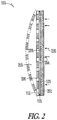
- FIG. 2 illustrates a cross-sectional view of portions of the fuel cell system 100, including fluid manifold 202, bond member 110, and fuel cell layer 112.
- the fuel cell layer 112 is coupled with portions of fluid manifold 202 via bond member 110, and in this way, creates one or more enclosed regions 208 therebetween.
- Bond member 110 can include any physical or chemical means, such as an adhesive member, a weld member, a solder member, a braze member, or mechanical fasteners or protrusions.
- bond member 110 can be a structural thermoset epoxy adhesive that may be cured under appropriate conditions of heat, pressure, or combinations thereof to create the bond between fluid manifold 202 and fuel cell layer 112. Heating and pressing may be done simultaneously or sequentially.
- enclosed region 208 has a thickness that is approximately equal to a cross-sectional thickness of bond member 110, such as about 0.05 mm or less.
- fluid manifold 202 and fuel cell layer 112 have a combined cross-sectional thickness of about 5mm or less, 1mm or less, or 0.6 mm or less.
- fluid manifold 202 may include a material directing recess 120 extending therethrough.
- Each material directing recess 120 receives, at an input 204, fuel flow 220 from fluid reservoir 102 ( FIG. 1 ) and provides, at an output 206, fuel flow 220 to the enclosed region 208.
- the fuel flow includes at least one of hydrogen, methanol, formic acid, butane, borohydride compounds (including sodium and potassium borohydride), or liquid organic hydrogen carriers.
- the continuing receipt of fuel flow 220 to the enclosed region 208 causes portions of fuel cell layer 112 to deform from a position adjacent the fluid manifold 202, thereby forming fluid plenum 210.
- Fluid plenum 210 is sufficient in size to serve as a fuel distribution plenum for the fuels cells incorporated in fuel cell layer 112.
- fluid reservoir 102 FIG. 1
- Fluid pressure regulator assembly 104 including an array of fluid pressure regulator devices 126 ( FIG. 1 ), can be used to reduce or maintain a pressure in fluid plenum 210 to a level sufficient for the operation and movement of the fuel cells in fuel cell layer 112, such as to the position shown in phantom.
- a distance between fluid manifold 202 and the fuel cell layer 112 is about 5 mm or less at the pressurized plenum state.
- a distance between fluid manifold 202 and the fuel cell layer 112 may be substantially the same in the pressurized plenum state as in the unpressurized plenum state, where deformation of the fuel cell layer may be very small.
- portions of the fuel cell layer may deform sufficient to transform the enclosed space into a fluid plenum while some portions may remain stationary.
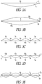
- FIGS. 3A-3E illustrate cross-sectional views of various other embodiments of the invention in which either the fuel cell layer or the fluid manifold or both deform to create a fluid plenum when the enclosed region is pressurized.
- fluid manifold 4 is a flexible component and fuel cell layer 2 is relatively rigid.
- fluid plenum 10 is created.
- FIG. 3B shows yet another alternative in which the system comprises two flexible components.
- two fluid plenums 10a, 10b are formed.
- FIGS. 3C-3E show yet further alternatives comprising internal supports such as bond members, spacers, collapsible columns, or the like, that are intended to at least restrict the outward expansion of the flexible layers in the assembly.
- internal supports such as bond members, spacers, collapsible columns, or the like. The reason for this is that during any movement, the flexible layers may change position or move outwardly and the risk of rupture increases. This approach may prevent such ruptures.
- FIG. 3C a cross sectional view of an embodiment comprising flexible fuel cell layer 2, relatively rigid fluid manifold 4, and internal supports is shown.
- One or more internal supports or bonds 5a-5c may be part of a gas management system, whose function may be, in part, to structurally support flexible fuel cell layer 2 during any movement thereof.
- fuel cell layer 2 is bonded at support sites 5a-5c to fluid manifold 4.
- the support sites at 5a-5c can be configured to align with one or more current collectors of the fuel cell layer and may employ a conductive epoxy adhesive in order to bond fluid manifold 4 to fuel cell layer 2.
- the conductive epoxy adhesive may be cured under appropriate conditions of heat, pressure, or combinations thereof. Heating and pressing may be done simultaneously or sequentially.
- the conductive epoxy may serve as part of the current collection system in the fuel cell and may be integral with fluid manifold 4, or may be in electrical contact with an electrically conductive portion of fluid manifold 4.
- a series of plenums 10-10d are formed by portions 2a-2d of fuel cell layer 2 as they inflated with pressurizing fluid.
- portions of the fuel cell layer may be directly bonded or attached to the fluid manifold, for example by way of an adhesive member.
- any deformation of the fuel cell layer may be extremely small, or almost imperceptible. For example, if the distance between subsequent bond members is sufficiently small, the unsupported area of the flexible fuel cell layer may also be small, and therefore the layer may not noticeably deform when the system is pressurized with a fluid.
- FIG. 3D shows an embodiment equivalent to that shown in FIG. 3C except that here, fluid manifold 4 is a flexible component and fuel cell layer 2 is relatively rigid. Again, bonds 5a-5c are made between fuel cell layer 2 and fluid manifold 4 thereby creating a series of enclosed regions. As before, these regions are transformed, via deformation of portions 4a-4d of fluid manifold 4, to become a series of fluid plenums 10a-10d when fluid pressure is admitted to the enclosed regions.
- FIG. 3E shows yet another alternative with internal supports (bonds) in which the system comprises two flexible components.
- the system comprises two flexible components.
- FIG. 3E there are two flexible fuel cell layers 2a, 2b bonded to fluid manifold 4 at the periphery and at several internal locations 5a-5c. Again, this forms a series of enclosed regions which, when pressurized with fluid, are transformed into numerous fluid plenums. (Note: in FIG. 3E , certain identifying indicia present in the preceding Figures have been omitted for purposes of avoiding clutter.)
- the flexibility of the system allows for fuel cell placement and utilization in spaces and sizes not previously practical.
- the fuel cell system may conform with or within the structure of the device to which it provides power.
- the fuel cell layer or fuel cells may be manufactured in a planar configuration, but then be bent, twisted or otherwise conformed to a non-planar configuration for positioning and/or use.
- the layer or layers may move during operation or remain unchanged in position during operation.
- the flexible fuel cell layer may be manufactured in a planar form, but then positioned in a non-planar configuration.
- Fuel cells according to the invention may be incorporated into the structure of any device which is powered, either in part or completely, by a fuel cell system.
- the invention consequently reduces the intrusion of the fuel cells within the envelope of the device being powered. This permits portable electrically-powered devices to be made more compact and/or permits the volume within the housing of a portable electronic device that would otherwise be occupied by batteries or another electrical power source to be used for other purposes.
- a flexible fuel cell may include flexible layers, such as first and second flexible layers.
- the flexible layers may be contacted by one or more bond members and there may be a space in between.
- the fuel cell layer may be coupled to a substrate, creating an enclosed space.
- the fuel cell layer may be positioned in a planar or non-planar configuration and be operable in such a self-supported position.
- the flexible layers include one or more fuel cells which may be thin-layer fuel cells or planar fuel cells in a two-dimensional array, for example.
- the fuel cells may be substantially integrated into the layer, such that the fuel cells are nearly or fully within the dimensions of the layer, for example.
- the flexible fuel cell layer may also include additional fuel cell components, such as current collection components.
- the current collection components may be in contact with two or more fuel cells present in the layer or layers.
- the current collection components may be substantially integrated within the layer, for example.
- fluidic control components may be integrated into the layer as well, such as pressure regulator devices.
- One or more fluid pressure regulator devices may be integrated and include an array of co-planar fluid pressure regulator devices, each fluidic pressure regulator device acting independently from the others.
- the one or more fuel cells may form an array made up of individual fuel cells that are arranged two-dimensionally in any of various suitable ways on an area covered by the array.
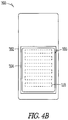
- cathode regions of individual fuel cells may be arranged to provide one or more of: one or two or more columns of substantially parallel stripes; shapes distributed at nodes of a two-dimensional lattice configuration (which could be a rectangular, square, triangular or hexagonal lattice, for example and which is not necessarily completely regular); a pattern of shapes distributed in both a width and a length dimension of the area covered by the array (such a pattern may be less regular than a lattice-type pattern), for example.
- Thin layer fuel cells may be arranged into bipolar or unipolar arrays constructed of very thin layers. Within such an array, individual unit fuel cells may be connected in a series or series-parallel arrangement. Connecting fuel cells in such an arrangement permits electrical power to be delivered from an array of fuel cells at increased voltages and reduced currents. This, in turn, permits electrical conductors having smaller cross-sectional areas to be used to collect the electrical current.
- individual unit fuel cells each produce electrical current at a voltage of less than 1 volt (typically about 0.6 volts) and enough individual fuel cells are connected in series within the array of fuel cells to produce an output voltage in excess of 6, 12, 48 or more volts.
- Providing output at higher voltages can be important because the electrical power produced by an array of fuel cells scales approximately with the area of the array. Therefore, for output at a fixed voltage, the current being supplied when the array of fuel cells is delivering its rated output power increases rapidly with the dimensions of the fuel cell array. Large and heavy conductors would be required to carry significant amounts of electrical power at the low output voltages provided by conventional unit fuel cells.
- a further feature of some thin layer fuel cells is that the thin layer fuel cells can include current collecting conductors that are embedded within the fuel cell layers themselves. This reduces or avoids the need to provide current collecting conductors external to the thin layer fuel cells.
- the thin layer fuel cells may provide arrays of unit fuel cells that do not require any special plumbing to allow air to contact the cathodes of the fuel cells.
- the unit fuel cells are arranged so that oxygen from ambient air present on one side of the array of fuel cells can readily contact cathodes of the unit cells.
- Thin layer fuel cells may comprise arrays of individual unit fuel cells that are organized in geometrical arrangements over a 2D surface. On one side of the surface, cathodes of the unit fuel cells are exposed at different locations on the surface for contact with an oxidant, such as air.
- These thin layers provide design flexibility by allowing integration of the fuel cells with the structure of the device they are to power.
- the invention reduces interior space requirements of the fuel cells, maximizing the volume available for fuel storage or other system components.
- fuel cells are provided in arrays which are less than about 5 mm thick (possibly not including a fuel plenum, if present).
- the fuel cells can be in the range of about 0.1 mm to about 2 mm thick, for example.
- Some fuel cell constructions can provide fuel cell layers that are even thinner than this.
- the layers can be free standing or supported. The layers can provide useful current and voltage levels, resulting in a power output that can be exploited by portable devices.
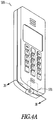
- FIG. 4A illustrates one example of a fuel cell-powered electronic device, and more specifically, a mobile phone 300 including the fuel cell system 100.
- the present fuel cell system 100 includes a space-saving fluid plenum 210 ( FIG. 2 ) transformable from a substantially volumeless enclosed region 208 ( FIG. 2 ). In this way, the fuel cell system 100 can be made in compact configurations to fit within an existing electronic device, such as the mobile phone 300. While a mobile phone 300 is shown in FIG.
- the present fuel cell system 100 can be configured in a small, compact volume for use with other portable electronics devices, such as laptop computers, computer accessories, displays, personal audio or video players, medical devices, televisions, transmitters, receivers, lighting devices including outdoor lighting or flashlights, electronic toys, power tools or any device conventionally used with batteries.
- portable electronics devices such as laptop computers, computer accessories, displays, personal audio or video players, medical devices, televisions, transmitters, receivers, lighting devices including outdoor lighting or flashlights, electronic toys, power tools or any device conventionally used with batteries.
- FIG. 4B illustrates a cross-sectional view of the mobile phone 300, such as along line 3B-3B of FIG. 4A .
- any internally positioned power source must be small and compact in size and shape.
- the present fuel cell system 100 including the substantially volumeless enclosed region 208 ( FIG. 2 ) transformable into the fluid plenum 210 ( FIG. 2 ) can meet such size and shape requirements.
- a battery cover 302 of the mobile phone 300 includes a pocket 304 about 0.6 mm deep to accommodate portions of the compact fuel cell system 100, such as the fluid manifold 202 ( FIG. 2 ) and the fuel cell layer 112 ( FIG. 2 ), which are coupled by the bond member 110 ( FIG. 2 ).
- the battery cover 302 provides an external support structure to limit the outward deformation of the fuel cell layer 112 away from the fluid manifold 202 during powering operations of the mobile phone 300.
- the battery cover 302 includes multiple air access ports 118 to allow the cathodes of the fuel cell layer 112 to receive air for use as an oxidizing agent.
- the present fuel cell system can be used to adequately power other electronic devices in addition to the mobile phone 300 ( FIGS. 4A-4B ), such as a laptop computer.
- the fuel cell system is positioned within an outer casing of the laptop display portion.
- the outer casing can include one or more air access ports to allow the fuel cell system with access to ambient air.
- the fuel cell system 100 can include one or more fluid pressure regulator devices 126 to control the flow of fuel pressure coming out of the fluid reservoir 102 ( FIG. 1 ) by reducing a primary (higher) fluid pressure present in the fluid reservoir 102 to a more constant secondary (lower) fluid pressure for delivery to the fuel cell layer 112 ( FIG. 1 ).
- a single fluid pressure regulator device 126 may be used or alternatively, it is contemplated that a fluid pressure regulator assembly 104 including multiple regulators 126 can be used with the present fuel cell system 100 ( FIG. 1 ).
- the present inventors have recognized that it may be beneficial in some examples for the fuel distribution flow to the enclosed region, and ultimately consumed by the anodes of the fuel cell layer 112, be uniform.
- the fluid pressure regulator assembly 104 can be used to provide active, local, and uniform control of fuel pressure and flow applied into and through (via material directing recesses 120 ) the fluid manifold 202.
- the multiple fluid regulator devices 126 can be formed on the same layers, resulting in co-planar fluid regulator devices. Further, multiple inlets and/or outlets may be employed to direct fluid to and from fluid manifold 202. And, further still, the inlets may be located on the major or the minor sides of fluid manifold 202.
- FIG. 5 illustrates a cross-section view of the array of fluid pressure regulator devices 126 of the fluid pressure regulator assembly 104, as constructed in accordance with an example.
- the array of fluid pressure regulator devices 126 can be spatially distributed so that each regulator distributes fuel or other reactant fluid into a different portion of the enclosed region 208.
- the enclosed region 208 is partitioned into a number of discrete regions 702 A , 702 B , 702 C , etc. as shown, with each region served by one or more fluid pressure regulator devices 126.
- each fluid pressure regulator device 126 acts independently from the others to maintain proper fuel pressure in the respective region of the enclosed region 208 for steady delivery of fuel to the anodes of the at least one fuel cell 112 ( FIG. 1 ).
- the fluid manifold 202 includes at least one conduit layer that, in an option, is relatively thin, for example, when compared with the length and width.
- the thickness of conduit layer 108 is generally less than about 1 mm.
- the thickness of conduit layer 108 is about 50 ⁇ m - 1 mm.
- the width and length of conduit layer 108 is about 1 mm and 100 mm, respectively. The width, length, or thickness can be altered for geometry of the fuel cell system 100 ( FIG. 1 ) in which the manifold is installed.
- Conduit layer 108 further includes at least one material directing recess 120 therein.
- Material directing recess 120 in an option, extends through the conduit layer 108, from one side to the other side.
- the conduit layer 108 is optionally formed of metals, plastics, elastomers, or composites.
- Material directing recess 120 can be etched, stamped, or otherwise created within or through the conduit layer 108.
- material directing recess 120 can be drilled within or through the conduit layer 108, formed with a laser, molded in the layer, formed via die cutting or otherwise machined in the layer.
- material directing recess 120 has a width of about 5 to 50 times the depth of the recess.
- recess 120 has a width about 1 mm - 2 mm.
- material directing recess 120 has a width of about 50 - 100 ⁇ m.
- the fluid manifold 202 further optionally includes at least one sealing layer 106 and can include first and second sealing layers on opposite sides of the conduit layer 108. This allows for material directing recess 120 to be enclosed and form a conduit thorough which material can travel.
- the sealing layers can be coupled with the conduit layer 120, for example, but not limited to, using adhesives, bonding techniques, laser welding, or various other conventional methods.
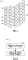
- FIG. 6 illustrates a block flow diagram 600 of a method of using a fuel cell system including a space-saving fluid plenum.
- a fluid may be introduced 602 into an enclosed region of a fuel cell system, sufficient to increase the pressure within the enclosed region.
- a stress may be imparted 604 to one or more portions of the fuel cell layer or the fluid manifold, sufficient to transform the enclosed region into a fluid plenum. The stress may cause a deformation in the fuel cell layer, fuel manifold or both, causing them to move away from each other.
- Introducing 602 the fluid may occur at a pressure less than a fluid reservoir pressure, for example.
- One or more fuel cells in the fuel cell layer may be activated upon introducing the fluid 602.
- Deforming 604 may include urging portions of the fuel cell layer about 5 mm or less away from the fluid manifold.
- the present fuel cell systems and methods include a space-saving fluid plenum transformable from a substantially volumeless enclosed region and in this way, allows for the creation of smaller, more compact fuel cell systems configurable to fit within an existing electronic device while still providing an effective structure to control the distribution of fluid, such as fuel, to the fuel cells.
- the enclosed region is located between a fluid manifold, which may include a fluid pressure regulator device(s), and a fuel cell layer.
- the enclosed region may be formed by a coupling between an outlet side of the fluid manifold and the fuel cell layer via a suitable bonding method.
- the coupling may be an adjacent bond, such that the enclosed space created is not able to function as a fluid distribution plenum without a stress being imparted on the fuel cell layer, fuel manifold or both by a fluid pressurization.
- the enclosed region transforms into a fluid plenum when a fluid exiting the manifold pressurizes the enclosed region, imparting a stress to one or more one or more portions of the fuel cell layer and/or the fluid manifold, which may result in portions or all of the layer and/or manifold to deform away from each other.
- the stress imparted may result in deformation sufficient to provide a fuel plenum which enables operation of the fuel cell layer, but which may or may not be visibly or externally perceptible.
- the curvature of the fuel cell layer and/or fluid manifold shown in the figures is for illustrative purposes, and in some embodiments, the fuel cell layer and/or fluid manifold may be less curved, or may be substantially planar.
- a flexible fuel cell layer with an array of strip-like fuel cells, constructed in accordance with commonly-owned US Patent Application 11/047,560 , arranged in a generally parallel formation was bonded to a generally rigid fluid manifold using a structural adhesive member to form a peripheral seal.
- the fuel cell system further comprised internal adhesive support members arranged in a parallel configuration such that the current collecting structures of the fuel cell array were bonded directly to the fluid manifold such that the fuel cell array was substantially adjacent to the fluid manifold.
- a flexible fuel cell layer with an array of strip-like fuel cells, constructed in accordance with commonly-owned US Patent Application 11/047,560 , arranged in a generally parallel formation was bonded to a generally rigid fluid manifold using a structural adhesive member to form a peripheral seal.
- No internal supports were used; however, the system was dimensionally constrained using an external framework, such that the fuel cell layer was constrained substantially adjacent to the fluid manifold.
- pressurized fluid e.g. hydrogen
- the fuel cell layer operated to produce electricity, confirming that a fluid plenum had been formed sufficient to enable fuel to react with the anodes of the fuel cell layer.
Description
- This non-provisional application claims the benefit of priority to
U.S. Provisional Patent Applications Serial Nos. 60/975,129 and60/975,132, filed September 25, 2007 - Portable electronic devices are trending to become smaller in size while increasing the demand for performance. As electronic components are designed smaller in size and incorporate sophisticated and complex technology, the demands on the associated power supply become greater. For instance, the power supply may need to occupy less volume or a smaller footprint to accommodate the addition of technology to the component or the decrease in overall component size. Further, the additional technology may require that the power supply last for longer periods of time or that power be delivered at uniform rates for steady electronic component performance.
- One example of a power supply is a fuel cell system. A fuel cell system may include one or multiple fuel cell layers, each layer comprising anodes, cathodes, and an electrolyte membrane interposed between the anodes and cathodes. A fuel cell system which includes such a layer typically includes a means for supplying air to the cathode or cathodes and a means for supply of fuel or other reactant fluid to the anode or anodes at an acceptable pressure level.
- In order to make a smaller fuel cell system, many technical requirements (e.g. sealing requirements) must still be met while attempting to accommodate the reduced space requirements. For instance, fluid supply components need to continue to supply fuel from a fluid supply to the anode or anodes of the fuel cell. This supply of fuel should be performed at an acceptable pressure level and delivery rate, without occupying an overall significant volume of the fuel cell system, and without compromising the performance of the fuel cell system.
-
US2007/090786 discloses a flexible fuel cell layer of the prior art. - Embodiments of the present invention relate to a fuel cell system. The system includes a fluid manifold having a first and a second side, at least one manifold outlet in the first side, and a manifold inlet fluidly coupled to the manifold outlet via a fluid directing recess located within the fluid manifold, a fuel cell layer including at least one fuel cell wherein at least a portion of the fuel cell layer is bonded to the first side of the fluid manifold such that the fuel cell layer is substantially adjacent to the first side of fluid manifold and an enclosed region formed by the bonded fuel cell layer and the fluid manifold. The one or more portions of the fuel cell layer or fluid manifold are adapted to deform away from each other upon pressurization of the enclosed region by fluid introduced through the manifold outlet.
- Embodiments also relate to a method of operating a fuel cell system including introducing a fluid into an enclosed region of a fuel cell system via a fluid manifold sufficient to increase the pressure within the enclosed region and imparting a stress to one or more portions of the fuel cell layer or the fluid manifold sufficient to transform the enclosed region into a fluid plenum.
- Embodiments relate to a flexible fuel cell layer. The layer includes two or more fuel cells substantially integrated within a two-dimensional layer, a substrate coupled to the layer forming an enclosed region between the substrate and layer. The layer can be positioned in a planar or non-planar configuration and the layer is configured such that it is operable when self-supported.
- In the drawings, like numerals describe similar components throughout the several views. Like numerals having different letter suffixes represent different instances of similar components. The drawings illustrate generally, by way of example, but not by way of limitation, various embodiments discussed in the present document.
- FIG. 1
- illustrates an exploded view of a fuel cell system, the fuel cell system including an enclosed region deformable into a fluid plenum when pressurized, according to some embodiments.
- FIG. 2
- illustrates a cross-sectional view of portions of a fuel cell system, including a fluid manifold, a bond member, and at least one fuel cell, according to some embodiments.
- FIGS. 3A-3E
- illustrate simplified cross-sectional views of various other embodiments in which either the fuel cell layer or the fluid manifold or both deform to create a fluid plenum when the enclosed region is pressurized, according to some embodiments.
- FIG. 4A
- illustrates an isometric view of a portable electronic device powered by a fuel cell system, according to some embodiments.
- FIG. 4B
- illustrates a cross-sectional view of a portable electronic device powered by a fuel cell system, such as along
line 3B-3B ofFIG. 4A , according to some embodiments. - FIG. 5
- illustrates a cross-sectional view of an array of fluid pressure regulator devices, according to some embodiments..
- FIG. 6
- illustrates a block flow diagram of a method of using a fuel cell system, according to some embodiments.
- The Detailed Description includes references to the accompanying drawings, which form a part of the Detailed Description. The drawings show, by way of illustration, specific embodiments in which the invention can be practiced. These embodiments are also referred to herein as "examples." All publications, patents, and patent documents referred to in this document are incorporated by reference herein in their entirety, as though individually incorporated by reference. In the event of inconsistent usages between this document and those documents so incorporated by reference, the usage in the incorporated reference(s) should be considered supplementary to that of this document; for irreconcilable inconsistencies, the usage in this document controls.
- In this document, the terms "a" or "an" are used, as is common in patent documents, to include one or more than one, independent of any other instances or usages of "at least one" or "one or more." In this document, the term "or" is used to refer to a nonexclusive or, such that "A or B" includes "A but not B," "B but not A," and "A and B," unless otherwise indicated.
- In the appended claims, the terms "including" and "in which" are used as the plain-English equivalents of the respective terms "comprising" and "wherein." Also, in the following claims, the terms "including" and "comprising" are open-ended, that is, a system, device, article, or process that includes elements in addition to those listed after such a term in a claim are still deemed to fall within the scope of that claim. Moreover, in the following claims, the terms "first," "second," and "third," etc. are used merely as labels, and are not intended to impose numerical requirements on their objects.
- Portable electronic devices, such as mobile phones, laptop computers, computer accessories, displays, personal audio or video players, medical devices, televisions, transmitters, receivers, lighting devices including outdoor lighting or flashlights, electronic toys, power tools or any device conventionally used with batteries, are trending to become smaller in size while increasing the demand for performance. Thus, fuel cell systems may need to occupy only a small volume of the overall electrical device volume, while still providing adequate distribution control of fuel or other reactant fluid to the fuel cell. Even so, current fuel cell systems are either too large to be used in the electrical devices or fail to provide the necessary fluid distribution control to allow the devices to function properly. As an example, current portable fuel cell-powered electronic devices are typically designed around the space required by the fuel cells and associated fuel storage, rather than the fuel cell system being designed to fit within the electronic device. Such order of design often results in undesirably bulky devices.
- The present inventors have recognized that, among other things, a fluid supply system with reduced volumetric requirements, but which is able to supply fuel or other reactant fluid to the anode or anodes of a fuel cell at an acceptable pressure level and in a uniform manner is needed. The present inventors have further recognized that a deformable enclosed region located between fluid control elements and the fuel cell allows fuel to be supplied to the anode or anodes at an acceptable pressure level and delivery rate, while allowing for a more compact fuel cell system.
- In one example, a fuel cell system includes a fluid manifold having first and second sides, at least one manifold outlet in the first side, and a manifold inlet fluidly coupled to the manifold outlet via a fluid directing recess located within the fluid manifold, a fuel cell layer including at least one fuel cell wherein a portion of the fuel cell layer is bonded to the first side of the fluid manifold (such as peripherally bonded), and an enclosed region formed by the bonded fuel cell layer and the fluid manifold.
- Initially (e.g. immediately after manufacture), the enclosed region may be essentially volumeless with the fuel cell layer adjacent to the first major side of a substrate, such as a fluid manifold. However, the fuel cell layer, the fluid manifold, or both may be flexible in whole or in part and thus may be deformed under application of modest pressure, or may include inherent material properties, such as elasticity, which enable the components to adapt in response to an imparted stress. Thus, one or more portions of the fuel cell layer or the fluid manifold may deform away from each other when the enclosed region is pressurized by fluid (e.g. fuel) from the manifold outlet. This transforms the enclosed region from being substantially volumeless into a region with sufficient volume to serve as a fluid distribution plenum for the fuel cell layer. Alternately, a stress imparted by the introduction of a pressurized fluid may result in the adaptation or modification of the fuel cell layer, a portion thereof, or the fluid manifold sufficient to transform the enclosed region, either chemically or physically, into a fluid plenum, such as a fuel plenum. If the fluid pressure is reduced again (e.g. after prolonged shutdown), the plenum may collapse in whole or in part depending on how elastic the components are. However, upon reapplication of fluid pressure, the enclosed region once again may inflate or otherwise transform sufficiently to serve as a fluid plenum.
- The described fuel cell systems and methods therefore have reduced volumetric requirements. Further, while the fuel cell system may additionally employ external supports or fixtures to support the fluid plenum formed between the fuel cell layer and fluid manifold, external supports or fixtures are not necessary. The flexible fuel cell layer and/or flexible fluid manifold are thus "self-supported" components, that is no external supports or fixturing are required for their function. Such "self-supported" flexible fuel cell layers are useful not only in the fabrication of systems in which there is initially no fluid plenum but they can be useful in other systems as well.
- In an example, a distance between the fluid manifold outlet side and the fuel cell layer at a non-pressurized enclosed region state is approximately equal to a cross-sectional thickness of a bond member. In another example, the fluid manifold and the fuel cell layer have a combined cross-sectional thickness of about 5 mm or less, about 1 mm or less, or about 0.6 mm or less at a non-pressurized enclosed region state.
- Among other things, the present systems and methods provide for fuel cell systems occupying less volume or a smaller footprint of an electronic component or device into which they are installed, while still meeting the power demands of the component or device. The present fuel cell systems and methods include a space-saving fluid plenum transformable from a substantially volumeless enclosed region and in this way, allows for the creation of smaller, more compact fuel cell systems configurable to fit within an existing electronic device. The enclosed region may be located between a substrate (i.e., fluid manifold) and at least one fuel cell layer. In an example, the enclosed region may be formed by a peripheral-type of coupling between an outlet side of the fluid manifold and the fuel cell layer via suitable bonding means (e.g. a bond member). In varying examples, the enclosed region transforms into a fluid plenum when a fluid exiting the fluid manifold pressurizes the enclosed region causing one or more portions of the fuel cell layer and/or the fluid manifold to deform away from each other. In an example, a distance between the outlet side of the fluid manifold and the fuel cell layer at a non-pressurized enclosed region state is approximately equal to a cross-sectional thickness of a bond member. In another example, the cross-sectional thickness of the bond member is about 0.05 mm or less. In another example, the cross-sectional thickness of the bond member is about 1 mm or less, or about 0.2 mm or less. As will be discussed below, the space-saving fluid plenum can be used in conjunction with other fuel cell components, such as a fluid reservoir, a fluid pressure regulator device(s), a fluid manifold, a bond member, a fuel cell, and an optional external support structure, to create a compact fuel cell system.
- As used herein, "flexible electrochemical layer" (or variant thereof) refers to include an electrochemical layer that is flexible in whole or in part, so-as-to embrace, for example, an electrochemical layer having one or more rigid components integrated with one or more flexible components. A "flexible fuel cell layer" refers to a layer comprising one or more fuel cells integrated into the layer.
- As used herein, "flexible two-dimensional (2-D) fuel cell array" refers to a flexible sheet which is thin in one dimension and which supports a number of fuel cells. A flexible two-dimensional fuel cell array may be an example of a flexible fuel cell layer. The fuel cells have active areas of one type (e.g. cathodes) that are accessible from one face of the sheet and active areas of another type (e.g. anodes) that are accessible from an opposed face of the sheet. The active areas may be disposed to lie within areas on their respective faces of the sheet (e.g. it is not mandatory that the entire sheet be covered with active areas, however, the performance of a fuel cell may be increased by increasing its active area.
- As used herein, "self-supported" refers to an electrochemical cell layer if, when coupled to a substrate, no external fixturing is required to create and/or maintain the integrity of a fuel plenum when in use.
- As used herein, "adjacent" or "adjacently", when used in the context of the fuel cell layer being adjacent to the fluid manifold, refers to a fuel cell layer is close enough proximity to the fluid manifold such that the enclosed region is too small to effectively function as a fluid distribution plenum.
- As used herein, "bonding member" refers to an implicit or explicit component that facilitates the coupling of two objects. In an example, an implicit bonding member may include an adhesive or weld. An explicit bonding member may include a mechanical fastener, for example.
- As used herein, "operable" refers to an electrochemical cell layer or individual electrochemical cell capable of producing an electrical current or voltage. For example, a fuel cell layer may be in an operable position and capable of producing electricity without further manipulation in position or configuration.
- As used herein, "substrate" refers to a component coupled to an electrochemical cell layer, sufficient to create an enclosed space. A substrate may include, among other things, a fluid manifold, a fuel cell system structural member, fluidic control components, fluid reservoir, a portion of an electronic device or a combination thereof. Fluidic control components may include pressure regulator devices, such as an array of regulators, for example.
- As used herein, "deform" or "deformation" refers to in general, the behaviour of a material, component, structure, or composite layer in response to an imparted stress. A deformation may be an intended result, or it may be an unintended side effect. A deformation may be of a large enough magnitude to be clearly visible to the naked eye (e.g on the order of millimeters), or may be small enough that it can only be detected with the aide of a microscope (e.g. on the order of micrometers or nanometers). A deformation may comprise the 'flexing' or 'bending' of a component, or may alternately comprise compression or other such change in shape of a component.
- Referring now to the drawings, particularly to
FIG. 1 , which illustrates an exploded view of afuel cell system 100 comprising, but not limited to, afluid reservoir 102, an optional fluidpressure regulator assembly 104 including multiple fluidpressure regulator devices 126, amanifold sealing layer 106, amanifold conduit layer 108, abond member 110, afuel cell layer 112, and anexternal support structure 114. Thefluid reservoir 102 provides fuel or other reactant fluid for thefuel cell system 100 and can be charged or refueled via acharge port 116. In an example, thefluid reservoir 102 can comprise a cellular fuel tank, such as is discussed in commonly-owned Zimmermann,U.S. Patent Application Serial No. 11/621,501 , entitled "CELLULAR RESERVOIR AND METHODS RELATED THERETO," or other fluid enclosure as is discussed in commonly-owned Zimmermann,U.S. Patent Application Serial No. 11/473,591 , entitled "FLUID ENCLOSURE AND METHODS RELATED THERETO." - A fluid manifold, which may optionally include one or more of the fluid
pressure regulator assembly 104, themanifold sealing layer 106, and themanifold conduit layer 108 provides for the distribution, regulation, and transfer of fuel from thefluid reservoir 102 to thefuel cell layer 112. In this example, the fluidpressure regulator assembly 104 controls the fuel pressure coming out of thefluid reservoir 102 by reducing a primary (higher) fluid pressure present therein to a more constant secondary (lower) fluid pressure for delivery to thefuel cell layer 112. A fluid manifold, including themanifold sealing layer 106, themanifold conduit layer 108, and the fluidpressure regulator assembly 104, is fluidly coupled to thefuel cell layer 112 via amaterial directing recess 120. Thematerial directing recess 120 of the fluid manifold directs the flow of fuel from the fluidpressure regulator assembly 104 to a region adjacent to thefuel cell layer 112, and can be formed by creating one or more channels in themanifold conduit layer 108, for example. In an example, the fluid manifold includes a layered structure that allows for the manifold to be of a size that does not take up unnecessary volume, nor an unnecessarily large footprint, yet allows for the pressure, volume, or temperature requirements forfuel cell systems 100 to be met, as is discussed in commonly-owned Schrooten et al.,U.S. Patent Application Serial No. 12/053,366 , entitled "FLUID MANIFOLD AND METHODS THEREFOR." - The
fuel cell layer 112 includes fuel cell layers (i.e., comprising at least one anode and cathode) with an electrolyte interposed therebetween. In an example, thefuel cell layer 112 utilized in thesystem 100 can be planar, as is discussed in commonly-ownedMcLean et al., U.S. Patent Application Serial No. 11/047,560 , entitled "ELECTROCHEMICAL CELLS HAVING CURRENT-CARRYING STRUCTURES UNDERLYING ELECTROCHEMICAL REACTION LAYERS." In such an example, an electric current-carrying structure that collects power generated by thefuel cell layer 112 underlies, at least in part, one of the fuel cell layers. - In the present invention, either the fuel cell layer or the fluid manifold is flexible such that it can be deformed under pressure. In such an example, one or more fuel cells are substantially integrated within a flexible electrochemical layer. The flexible electrochemical layer may optionally include one or more rigid components, and thus, may not be flexible in its entirety. In operation of the
fuel cell system 100, the anode of each cell receives the fuel from thefluid reservoir 102 and the cathode of each cell receives air containing oxygen as an oxidizing agent via one or moreair access ports 118 in theexternal support structure 114, for example. -
FIG. 2 illustrates a cross-sectional view of portions of thefuel cell system 100, includingfluid manifold 202,bond member 110, andfuel cell layer 112. Thefuel cell layer 112 is coupled with portions offluid manifold 202 viabond member 110, and in this way, creates one or moreenclosed regions 208 therebetween.Bond member 110 can include any physical or chemical means, such as an adhesive member, a weld member, a solder member, a braze member, or mechanical fasteners or protrusions. For instance,bond member 110 can be a structural thermoset epoxy adhesive that may be cured under appropriate conditions of heat, pressure, or combinations thereof to create the bond betweenfluid manifold 202 andfuel cell layer 112. Heating and pressing may be done simultaneously or sequentially. In an example,enclosed region 208 has a thickness that is approximately equal to a cross-sectional thickness ofbond member 110, such as about 0.05 mm or less. In another example,fluid manifold 202 andfuel cell layer 112 have a combined cross-sectional thickness of about 5mm or less, 1mm or less, or 0.6 mm or less. - As shown,
fluid manifold 202 may include amaterial directing recess 120 extending therethrough. Eachmaterial directing recess 120 receives, at aninput 204,fuel flow 220 from fluid reservoir 102 (FIG. 1 ) and provides, at anoutput 206,fuel flow 220 to theenclosed region 208. In an example, the fuel flow includes at least one of hydrogen, methanol, formic acid, butane, borohydride compounds (including sodium and potassium borohydride), or liquid organic hydrogen carriers. The continuing receipt offuel flow 220 to theenclosed region 208 causes portions offuel cell layer 112 to deform from a position adjacent thefluid manifold 202, thereby formingfluid plenum 210.Fluid plenum 210 is sufficient in size to serve as a fuel distribution plenum for the fuels cells incorporated infuel cell layer 112. In operation, fluid reservoir 102 (FIG. 1 ) is filled with fuel by pressurizing the charge port 116 (FIG. 1 ). Fluidpressure regulator assembly 104, including an array of fluid pressure regulator devices 126 (FIG. 1 ), can be used to reduce or maintain a pressure influid plenum 210 to a level sufficient for the operation and movement of the fuel cells infuel cell layer 112, such as to the position shown in phantom. In an example, a distance betweenfluid manifold 202 and thefuel cell layer 112 is about 5 mm or less at the pressurized plenum state. In some embodiments, a distance betweenfluid manifold 202 and thefuel cell layer 112 may be substantially the same in the pressurized plenum state as in the unpressurized plenum state, where deformation of the fuel cell layer may be very small. In some embodiments, such as when the system includes internal supports, portions of the fuel cell layer may deform sufficient to transform the enclosed space into a fluid plenum while some portions may remain stationary. -
FIGS. 3A-3E illustrate cross-sectional views of various other embodiments of the invention in which either the fuel cell layer or the fluid manifold or both deform to create a fluid plenum when the enclosed region is pressurized. InFIG. 3A ,fluid manifold 4 is a flexible component andfuel cell layer 2 is relatively rigid. When fluid is admitted to the enclosed region in between,fluid plenum 10 is created. (Compare this embodiment to that inFIG. 2 in whichfuel cell layer 112 is flexible andfluid manifold 202 is relatively rigid.)FIG. 3B shows yet another alternative in which the system comprises two flexible components. InFIG. 3B , there are two flexiblefuel cell layers fluid manifold 4. Upon pressurizing the enclosed regions therebetween, twofluid plenums -
FIGS. 3C-3E show yet further alternatives comprising internal supports such as bond members, spacers, collapsible columns, or the like, that are intended to at least restrict the outward expansion of the flexible layers in the assembly. The reason for this is that during any movement, the flexible layers may change position or move outwardly and the risk of rupture increases. This approach may prevent such ruptures. Referring toFIG. 3C , a cross sectional view of an embodiment comprising flexiblefuel cell layer 2, relatively rigidfluid manifold 4, and internal supports is shown. One or more internal supports orbonds 5a-5c may be part of a gas management system, whose function may be, in part, to structurally support flexiblefuel cell layer 2 during any movement thereof. (One example of movement may be a result of the pressurization and depressurization of a plenum inspaces 10a-10d.) As shown inFIG. 3C ,fuel cell layer 2 is bonded atsupport sites 5a-5c tofluid manifold 4. In particular, the support sites at 5a-5c can be configured to align with one or more current collectors of the fuel cell layer and may employ a conductive epoxy adhesive in order to bondfluid manifold 4 tofuel cell layer 2. The conductive epoxy adhesive may be cured under appropriate conditions of heat, pressure, or combinations thereof. Heating and pressing may be done simultaneously or sequentially. The conductive epoxy may serve as part of the current collection system in the fuel cell and may be integral withfluid manifold 4, or may be in electrical contact with an electrically conductive portion offluid manifold 4. As a result, a series of plenums 10-10d are formed byportions 2a-2d offuel cell layer 2 as they inflated with pressurizing fluid. In some embodiments, portions of the fuel cell layer may be directly bonded or attached to the fluid manifold, for example by way of an adhesive member. In embodiments such as that shown inFIG. 3C , any deformation of the fuel cell layer may be extremely small, or almost imperceptible. For example, if the distance between subsequent bond members is sufficiently small, the unsupported area of the flexible fuel cell layer may also be small, and therefore the layer may not noticeably deform when the system is pressurized with a fluid. -
FIG. 3D shows an embodiment equivalent to that shown inFIG. 3C except that here,fluid manifold 4 is a flexible component andfuel cell layer 2 is relatively rigid. Again,bonds 5a-5c are made betweenfuel cell layer 2 andfluid manifold 4 thereby creating a series of enclosed regions. As before, these regions are transformed, via deformation ofportions 4a-4d offluid manifold 4, to become a series offluid plenums 10a-10d when fluid pressure is admitted to the enclosed regions. -
FIG. 3E shows yet another alternative with internal supports (bonds) in which the system comprises two flexible components. InFIG. 3E , there are two flexiblefuel cell layers fluid manifold 4 at the periphery and at severalinternal locations 5a-5c. Again, this forms a series of enclosed regions which, when pressurized with fluid, are transformed into numerous fluid plenums.
(Note: inFIG. 3E , certain identifying indicia present in the preceding Figures have been omitted for purposes of avoiding clutter.) - The flexibility of the system allows for fuel cell placement and utilization in spaces and sizes not previously practical. The fuel cell system may conform with or within the structure of the device to which it provides power. The fuel cell layer or fuel cells may be manufactured in a planar configuration, but then be bent, twisted or otherwise conformed to a non-planar configuration for positioning and/or use. The layer or layers may move during operation or remain unchanged in position during operation. The flexible fuel cell layer may be manufactured in a planar form, but then positioned in a non-planar configuration.
- Fuel cells according to the invention may be incorporated into the structure of any device which is powered, either in part or completely, by a fuel cell system. The invention consequently reduces the intrusion of the fuel cells within the envelope of the device being powered. This permits portable electrically-powered devices to be made more compact and/or permits the volume within the housing of a portable electronic device that would otherwise be occupied by batteries or another electrical power source to be used for other purposes.
- A flexible fuel cell may include flexible layers, such as first and second flexible layers. The flexible layers may be contacted by one or more bond members and there may be a space in between. The fuel cell layer may be coupled to a substrate, creating an enclosed space. The fuel cell layer may be positioned in a planar or non-planar configuration and be operable in such a self-supported position.
- The flexible layers include one or more fuel cells which may be thin-layer fuel cells or planar fuel cells in a two-dimensional array, for example. The fuel cells may be substantially integrated into the layer, such that the fuel cells are nearly or fully within the dimensions of the layer, for example. The flexible fuel cell layer may also include additional fuel cell components, such as current collection components. The current collection components may be in contact with two or more fuel cells present in the layer or layers. The current collection components may be substantially integrated within the layer, for example. In addition, fluidic control components may be integrated into the layer as well, such as pressure regulator devices. One or more fluid pressure regulator devices may be integrated and include an array of co-planar fluid pressure regulator devices, each fluidic pressure regulator device acting independently from the others.
- The one or more fuel cells may form an array made up of individual fuel cells that are arranged two-dimensionally in any of various suitable ways on an area covered by the array. For example, cathode regions of individual fuel cells may be arranged to provide one or more of: one or two or more columns of substantially parallel stripes; shapes distributed at nodes of a two-dimensional lattice configuration (which could be a rectangular, square, triangular or hexagonal lattice, for example and which is not necessarily completely regular); a pattern of shapes distributed in both a width and a length dimension of the area covered by the array (such a pattern may be less regular than a lattice-type pattern), for example.
- Thin layer fuel cells may be arranged into bipolar or unipolar arrays constructed of very thin layers. Within such an array, individual unit fuel cells may be connected in a series or series-parallel arrangement. Connecting fuel cells in such an arrangement permits electrical power to be delivered from an array of fuel cells at increased voltages and reduced currents. This, in turn, permits electrical conductors having smaller cross-sectional areas to be used to collect the electrical current.
- For example, in some embodiments, individual unit fuel cells each produce electrical current at a voltage of less than 1 volt (typically about 0.6 volts) and enough individual fuel cells are connected in series within the array of fuel cells to produce an output voltage in excess of 6, 12, 48 or more volts. Providing output at higher voltages can be important because the electrical power produced by an array of fuel cells scales approximately with the area of the array. Therefore, for output at a fixed voltage, the current being supplied when the array of fuel cells is delivering its rated output power increases rapidly with the dimensions of the fuel cell array. Large and heavy conductors would be required to carry significant amounts of electrical power at the low output voltages provided by conventional unit fuel cells.
- A further feature of some thin layer fuel cells is that the thin layer fuel cells can include current collecting conductors that are embedded within the fuel cell layers themselves. This reduces or avoids the need to provide current collecting conductors external to the thin layer fuel cells.
- Conventional fuel cell stacks may require internal plumbing to carry air and oxidant to each unit fuel cell, but the thin layer fuel cells may provide arrays of unit fuel cells that do not require any special plumbing to allow air to contact the cathodes of the fuel cells. The unit fuel cells are arranged so that oxygen from ambient air present on one side of the array of fuel cells can readily contact cathodes of the unit cells. Thin layer fuel cells may comprise arrays of individual unit fuel cells that are organized in geometrical arrangements over a 2D surface. On one side of the surface, cathodes of the unit fuel cells are exposed at different locations on the surface for contact with an oxidant, such as air.
- These thin layers provide design flexibility by allowing integration of the fuel cells with the structure of the device they are to power. The invention reduces interior space requirements of the fuel cells, maximizing the volume available for fuel storage or other system components.
- In some embodiments of the invention, fuel cells are provided in arrays which are less than about 5 mm thick (possibly not including a fuel plenum, if present). The fuel cells can be in the range of about 0.1 mm to about 2 mm thick, for example. Some fuel cell constructions can provide fuel cell layers that are even thinner than this. The layers can be free standing or supported. The layers can provide useful current and voltage levels, resulting in a power output that can be exploited by portable devices.
- Examples of flexible fuel cell layers that may adapted for use in the present invention may be found in commonly-owned McLean, et. al.,
U.S. Patent Application Serial No. 11/327,516 , entitled "FLEXIBLE FUEL CELL STRUCTURES HAVING EXTERNAL SUPPORT". -
FIG. 4A illustrates one example of a fuel cell-powered electronic device, and more specifically, amobile phone 300 including thefuel cell system 100. As discussed above, the presentfuel cell system 100 includes a space-saving fluid plenum 210 (FIG. 2 ) transformable from a substantially volumeless enclosed region 208 (FIG. 2 ). In this way, thefuel cell system 100 can be made in compact configurations to fit within an existing electronic device, such as themobile phone 300. While amobile phone 300 is shown inFIG. 4A , the presentfuel cell system 100 can be configured in a small, compact volume for use with other portable electronics devices, such as laptop computers, computer accessories, displays, personal audio or video players, medical devices, televisions, transmitters, receivers, lighting devices including outdoor lighting or flashlights, electronic toys, power tools or any device conventionally used with batteries. -
FIG. 4B illustrates a cross-sectional view of themobile phone 300, such as alongline 3B-3B ofFIG. 4A . Due to the very limited amount of space inside themobile phone 300, any internally positioned power source must be small and compact in size and shape. Beneficially, the presentfuel cell system 100 including the substantially volumeless enclosed region 208 (FIG. 2 ) transformable into the fluid plenum 210 (FIG. 2 ) can meet such size and shape requirements. In an example, abattery cover 302 of themobile phone 300 includes apocket 304 about 0.6 mm deep to accommodate portions of the compactfuel cell system 100, such as the fluid manifold 202 (FIG. 2 ) and the fuel cell layer 112 (FIG. 2 ), which are coupled by the bond member 110 (FIG. 2 ). In another example, thebattery cover 302 provides an external support structure to limit the outward deformation of thefuel cell layer 112 away from thefluid manifold 202 during powering operations of themobile phone 300. In this example, thebattery cover 302 includes multipleair access ports 118 to allow the cathodes of thefuel cell layer 112 to receive air for use as an oxidizing agent. - The present fuel cell system can be used to adequately power other electronic devices in addition to the mobile phone 300 (
FIGS. 4A-4B ), such as a laptop computer. The fuel cell system is positioned within an outer casing of the laptop display portion. The outer casing can include one or more air access ports to allow the fuel cell system with access to ambient air. - As discussed above, the
fuel cell system 100 can include one or more fluidpressure regulator devices 126 to control the flow of fuel pressure coming out of the fluid reservoir 102 (FIG. 1 ) by reducing a primary (higher) fluid pressure present in thefluid reservoir 102 to a more constant secondary (lower) fluid pressure for delivery to the fuel cell layer 112 (FIG. 1 ). - A single fluid
pressure regulator device 126 may be used or alternatively, it is contemplated that a fluidpressure regulator assembly 104 includingmultiple regulators 126 can be used with the present fuel cell system 100 (FIG. 1 ). The present inventors have recognized that it may be beneficial in some examples for the fuel distribution flow to the enclosed region, and ultimately consumed by the anodes of thefuel cell layer 112, be uniform. Thus, instead of relying on a single point of fluid pressure regulation control from thefluid reservoir 102 and single inlet to thefluid manifold 202, the fluidpressure regulator assembly 104 can be used to provide active, local, and uniform control of fuel pressure and flow applied into and through (via material directing recesses 120) thefluid manifold 202. In an example, the multiplefluid regulator devices 126 can be formed on the same layers, resulting in co-planar fluid regulator devices. Further, multiple inlets and/or outlets may be employed to direct fluid to and fromfluid manifold 202. And, further still, the inlets may be located on the major or the minor sides offluid manifold 202. -
FIG. 5 illustrates a cross-section view of the array of fluidpressure regulator devices 126 of the fluidpressure regulator assembly 104, as constructed in accordance with an example. As shown inFIG. 5 , the array of fluidpressure regulator devices 126 can be spatially distributed so that each regulator distributes fuel or other reactant fluid into a different portion of theenclosed region 208. In an example, theenclosed region 208 is partitioned into a number ofdiscrete regions pressure regulator devices 126. In another example, each fluidpressure regulator device 126 acts independently from the others to maintain proper fuel pressure in the respective region of theenclosed region 208 for steady delivery of fuel to the anodes of the at least one fuel cell 112 (FIG. 1 ). - The
fluid manifold 202 includes at least one conduit layer that, in an option, is relatively thin, for example, when compared with the length and width. In an example, the thickness ofconduit layer 108 is generally less than about 1 mm. In another example, the thickness ofconduit layer 108 is about 50 µm - 1 mm. In another example, the width and length ofconduit layer 108 is about 1 mm and 100 mm, respectively. The width, length, or thickness can be altered for geometry of the fuel cell system 100 (FIG. 1 ) in which the manifold is installed. -
Conduit layer 108 further includes at least onematerial directing recess 120 therein.Material directing recess 120, in an option, extends through theconduit layer 108, from one side to the other side. Theconduit layer 108 is optionally formed of metals, plastics, elastomers, or composites.Material directing recess 120 can be etched, stamped, or otherwise created within or through theconduit layer 108. In another option,material directing recess 120 can be drilled within or through theconduit layer 108, formed with a laser, molded in the layer, formed via die cutting or otherwise machined in the layer. In an example,material directing recess 120 has a width of about 5 to 50 times the depth of the recess. In another example,recess 120 has a width about 1 mm - 2 mm. In yet another example,material directing recess 120 has a width of about 50 - 100 µm. - The
fluid manifold 202 further optionally includes at least onesealing layer 106 and can include first and second sealing layers on opposite sides of theconduit layer 108. This allows formaterial directing recess 120 to be enclosed and form a conduit thorough which material can travel. The sealing layers can be coupled with theconduit layer 120, for example, but not limited to, using adhesives, bonding techniques, laser welding, or various other conventional methods. -
FIG. 6 illustrates a block flow diagram 600 of a method of using a fuel cell system including a space-saving fluid plenum. A fluid may be introduced 602 into an enclosed region of a fuel cell system, sufficient to increase the pressure within the enclosed region. A stress may be imparted 604 to one or more portions of the fuel cell layer or the fluid manifold, sufficient to transform the enclosed region into a fluid plenum. The stress may cause a deformation in the fuel cell layer, fuel manifold or both, causing them to move away from each other. Introducing 602 the fluid may occur at a pressure less than a fluid reservoir pressure, for example. One or more fuel cells in the fuel cell layer may be activated upon introducing thefluid 602.Deforming 604 may include urging portions of the fuel cell layer about 5 mm or less away from the fluid manifold. - The present fuel cell systems and methods include a space-saving fluid plenum transformable from a substantially volumeless enclosed region and in this way, allows for the creation of smaller, more compact fuel cell systems configurable to fit within an existing electronic device while still providing an effective structure to control the distribution of fluid, such as fuel, to the fuel cells. The enclosed region is located between a fluid manifold, which may include a fluid pressure regulator device(s), and a fuel cell layer. The enclosed region may be formed by a coupling between an outlet side of the fluid manifold and the fuel cell layer via a suitable bonding method. The coupling may be an adjacent bond, such that the enclosed space created is not able to function as a fluid distribution plenum without a stress being imparted on the fuel cell layer, fuel manifold or both by a fluid pressurization. In varying examples, the enclosed region transforms into a fluid plenum when a fluid exiting the manifold pressurizes the enclosed region, imparting a stress to one or more one or more portions of the fuel cell layer and/or the fluid manifold, which may result in portions or all of the layer and/or manifold to deform away from each other. In some embodiments, the stress imparted may result in deformation sufficient to provide a fuel plenum which enables operation of the fuel cell layer, but which may or may not be visibly or externally perceptible. The curvature of the fuel cell layer and/or fluid manifold shown in the figures is for illustrative purposes, and in some embodiments, the fuel cell layer and/or fluid manifold may be less curved, or may be substantially planar.
- In an example, a flexible fuel cell layer with an array of strip-like fuel cells, constructed in accordance with commonly-owned
US Patent Application 11/047,560 - In a second example a flexible fuel cell layer with an array of strip-like fuel cells, constructed in accordance with commonly-owned
US Patent Application 11/047,560 - The above description is intended to be illustrative, and not restrictive. For example, the above-described examples (or one or more features thereof) may be used in combination with each other. Other embodiments can be used, such as by one of ordinary skill in the art upon reviewing the above description. Also, in the above Detailed Description, various features may be grouped together to streamline the disclosure. This should not be interpreted as intending that an unclaimed disclosed feature is essential to any claim. Rather, inventive subject matter may lie in less than all features of a particular disclosed embodiment. In addition, while the majority of this patent document discusses fuel or reactant based fluid applications, the present systems and methods can be used for other fluid transfer applications in ways similar to those discussed herein. Thus, the following claims are hereby incorporated into the Detailed Description, with each claim standing on its own as a separate embodiment. The scope of the invention is defined by the appended claims.
Claims (20)
- A flexible fuel cell layer (112), comprising:two or more fuel cells integrated within a two-dimensional layer comprising a sheet supporting the two or more fuel cells;a substrate (202), coupled to the two-dimensional layer and forming an enclosed region (210) between the substrate and the two-dimensional layer, the enclosed region being inflatable in use and wherein pressurization of the enclosed region (210) with a fluid causes the enclosed region to inflate thereby transforming the enclosed region into a fuel plenum; andone or more internal supports (5a, 5b, 5c) positioned in the enclosed region and in contact with both the two-dimensional layer and the substrate, the one or more internal supports configured to at least restrict the outward expansion of the flexible layers when inflated in use whereby the flexible fuel cell layer is configured such that no external fixturing is required to create or maintain integrity of a fuel plenum when the flexible fuel cell layer is in use.
- The flexible fuel cell layer of claim 1, wherein the substrate (202) comprises a fuel cell system structural member, fluidic control components, a fluid pressure regulatory device, a fluid reservoir or a combination thereof.
- The flexible fuel cell layer of any one of claims 1-2, further comprising current collection components in contact with the two or more fuel cells and substantially integrated within the two-dimensional layer.
- The flexible fuel cell layer of any one of claims 1-3, wherein the one or more internal supports (5a, 5b, 5c) comprise a bond member, wherein the bond member is adapted to bond at least a portion of the two-dimensional layer to at least a portion of the substrate.
- The fuel cell layer of claim 4, wherein at least a portion of the bond member is electrically conductive.
- The fuel cell layer of claim 5, wherein the bond member is in contact with one or more electrically conductive portions of the substrate (202).
- The fuel cell layer of any of claims 1-6, wherein the one or more internal supports comprise bond members, spacers, collapsible columns, or a combination thereof.
- The fuel cell layer of any of claims 1-7, wherein the one or more internal supports collapse or expand in response to movement in the fuel cell layer or the substrate.
- The fuel cell layer of any of claims 4-6, wherein the bond member includes at least one of an adhesive member, a weld member, a solder member, a braze member, or a mechanical fastener.
- The fuel cell layer of any of claims 1-9, wherein the fuel cell layer is provided with an external support structure disposed to limit the outward deformation of the fuel cell layer or the fluid manifold away from each other.
- The fuel cell layer of any one of claims 1-10, wherein the enclosed region (210) is defined in part by the two or more fuel cells.
- The fuel cell layer of any one of claim 1-10, wherein the enclosed region (210) is in fluid communication with a fuel supply.
- A fuel cell system comprising:the flexible fuel cell layer of any of claims 1-12, wherein the substrate comprises a fluid manifold including:a first and a second side,at least one manifold outlet in the first side, anda manifold inlet fluidly coupled to the manifold outlet via a fluid directing recess located within the fluid manifold; andwherein at least a portion of the fuel cell layer is bonded to the first side of the fluid manifold such that the fuel cell layer is substantially adjacent to the first side of fluid manifold; andwherein one or more portions of the fuel cell layer or fluid manifold are adapted to deform away from each other upon pressurization of the enclosed region by fluid introduced through the manifold outlet.
- The fuel cell system of claim 13, wherein the fluid manifold, the fuel cell layer, or both is flexible and adapted to deform upon pressurization of the enclosed region.
- The fuel cell system of any one of claims 13-14, further comprising one or more additional fuel cell layers, a portion of which is bonded on the first side or a second side of the fluid manifold.
- The fuel cell system of any one of claims 13-15, wherein the enclosed region includes at least two discrete regions, each region pressurized by at least one different manifold outlet.
- The fuel cell system of any one of claims 13-16, wherein the fluid manifold includes at least one fluid pressure regulator device fluidly coupled with at least one material directing recess within the fluid manifold.
- The fuel cell system of any one of claims 13-17, wherein the fuel cell layer can be positioned in a planar or a non-planar configuration for operation.
- A method of operating a fuel cell system, comprising:introducing a fluid into an enclosed region of the fuel cell system of any one of claims 14 to 18 via the fluid manifold,wherein the introducing of the fluid is sufficient to increase the pressure within the enclosed region and inflate the enclosed region; andimparting a stress to one or more portions of a fuel cell layer or the fluid manifold, the fuel cell layer including at least one fuel cell in which a portion of the fuel cell layer is adjacently bonded to the first side of the fluid manifold using internal supports, creating the enclosed region, the one or more internal supports restricting the outward expansion of the enclosed region;wherein imparting the stress is sufficient to transform the enclosed region into a fluid plenum.
- The method of claim 19, wherein imparting a stress comprises one or more portions of the fuel cell layer or the fluid manifold deforming away from each other.
Applications Claiming Priority (3)
| Application Number | Priority Date | Filing Date | Title |
|---|---|---|---|
| US97512907P | 2007-09-25 | 2007-09-25 | |
| US97513207P | 2007-09-25 | 2007-09-25 | |
| PCT/CA2008/001713 WO2009039656A1 (en) | 2007-09-25 | 2008-09-25 | Fuel cell systems including space-saving fluid plenum and related methods |
Publications (3)
| Publication Number | Publication Date |
|---|---|
| EP2210303A1 EP2210303A1 (en) | 2010-07-28 |
| EP2210303A4 EP2210303A4 (en) | 2012-08-01 |
| EP2210303B1 true EP2210303B1 (en) | 2017-04-05 |
Family
ID=40471968
Family Applications (1)
| Application Number | Title | Priority Date | Filing Date |
|---|---|---|---|
| EP08800400.7A Not-in-force EP2210303B1 (en) | 2007-09-25 | 2008-09-25 | Fuel cell systems including space-saving fluid plenum and related methods |
Country Status (8)
| Country | Link |
|---|---|
| US (2) | US8790842B2 (en) |
| EP (1) | EP2210303B1 (en) |
| JP (3) | JP5453274B2 (en) |
| KR (1) | KR101588403B1 (en) |
| CN (2) | CN101849312B (en) |
| CA (1) | CA2700832A1 (en) |
| HK (1) | HK1149120A1 (en) |
| WO (1) | WO2009039656A1 (en) |
Families Citing this family (29)
| Publication number | Priority date | Publication date | Assignee | Title |
|---|---|---|---|---|
| US7378176B2 (en) | 2004-05-04 | 2008-05-27 | Angstrom Power Inc. | Membranes and electrochemical cells incorporating such membranes |
| US7632587B2 (en) | 2004-05-04 | 2009-12-15 | Angstrom Power Incorporated | Electrochemical cells having current-carrying structures underlying electrochemical reaction layers |
| TWI389829B (en) | 2006-06-30 | 2013-03-21 | Global Fresh Foods | System and methods for transporting or storing oxidatively-degradable foodstuff |
| US8133629B2 (en) | 2007-03-21 | 2012-03-13 | SOCIéTé BIC | Fluidic distribution system and related methods |
| KR101462131B1 (en) * | 2007-03-21 | 2014-11-17 | 소시에떼 비아이씨 | Fluid manifold and method therefor |
| JP5453274B2 (en) | 2007-09-25 | 2014-03-26 | ソシエテ ビック | Fuel cell system including space-saving fluid plenum and method related thereto |
| JP5620637B2 (en) | 2007-12-21 | 2014-11-05 | ソシエテ ビックSociete Bic | Chemical battery member having discontinuous regions |
| ES2404562T3 (en) | 2008-01-17 | 2013-05-28 | SOCIéTé BIC | Covers for electrochemical cells and corresponding procedures |
| WO2009105896A1 (en) * | 2008-02-29 | 2009-09-03 | Angstrom Power Incorporated | Electrochemical cell and membranes related thereto |
| US8877271B2 (en) * | 2009-10-30 | 2014-11-04 | Global Fresh Foods | Perishable food storage units |
| AR078820A1 (en) | 2009-10-30 | 2011-12-07 | Global Fresh Foods | SYSTEMS AND METHODS FOR CONSERVING LOST FOODS |
| US9468220B2 (en) * | 2009-10-30 | 2016-10-18 | Global Fresh Foods | System and method for maintaining perishable foods |
| CA2785057A1 (en) * | 2009-12-28 | 2011-07-07 | Societe Bic | Fuel cells and fuel cell components having asymmetric architecture and methods thereof |
| US9397351B2 (en) * | 2009-12-28 | 2016-07-19 | Intelligent Energy Limited | Apparatus and methods for connecting fuel cells to an external circuit |
| US8785077B2 (en) | 2009-12-28 | 2014-07-22 | Societe Bic | Apparatus and methods for connecting fuel cells to an external circuit |
| EP2759013B1 (en) | 2011-09-23 | 2018-03-21 | Intelligent Energy Limited | Methods of forming arrays of fuel cells on a composite surface |
| US10096845B2 (en) | 2011-11-18 | 2018-10-09 | Intelligent Energy Limited | Methods of forming fuel cell layers |
| CN104054192B (en) | 2011-11-18 | 2017-10-03 | 智慧能量有限公司 | The periphery coupling of planar fuel cells and correlation technique |
| WO2013145776A1 (en) | 2012-03-30 | 2013-10-03 | Sanyo Electric Co., Ltd. | Fuel cell system comprising a detachable fuel cartridge including a hydrogen storage alloy |
| US9318754B2 (en) * | 2012-08-28 | 2016-04-19 | Intelligent Energy Limited | Enhanced bonding in fuel cells |
| US9577273B2 (en) | 2013-03-15 | 2017-02-21 | Intelligent Energy Limited | Fluidic interface module for a fuel cell system |
| US10193169B2 (en) | 2013-03-15 | 2019-01-29 | Intelligent Energy Limited | Fluidic interface module for a fuel cell system |
| US9680171B2 (en) | 2013-03-15 | 2017-06-13 | Intelligent Energy Limited | Methods for operating a fuel cell system |
| FR3014247B1 (en) * | 2013-11-29 | 2016-01-01 | Commissariat Energie Atomique | METHOD FOR MANUFACTURING MEMBRANE ASSEMBLY / ELECTRODES COMPRISING REINFORCEMENTS |
| US9954235B2 (en) | 2014-12-22 | 2018-04-24 | Intelligent Energy Limited | Anode chambers with variable volumes |
| US10211478B2 (en) * | 2015-10-07 | 2019-02-19 | Bloom Energy Corporation | Fuel cell stack column including stress-relief components |
| FR3062960B1 (en) * | 2017-02-10 | 2021-05-21 | Commissariat Energie Atomique | FUEL CELL |
| FR3062958B1 (en) | 2017-02-10 | 2019-04-05 | Commissariat A L'energie Atomique Et Aux Energies Alternatives | ELEMENTARY MODULE OF A FUEL CELL |
| FR3062959A1 (en) * | 2017-02-10 | 2018-08-17 | Commissariat A L'energie Atomique Et Aux Energies Alternatives | ELEMENTARY MODULE FOR FUEL CELL |
Family Cites Families (133)
| Publication number | Priority date | Publication date | Assignee | Title |
|---|---|---|---|---|
| FR1452564A (en) | 1964-11-17 | 1966-09-09 | Gen Electric | Fuel cells, solid electrolyte, high voltage |
| US3402230A (en) | 1965-06-21 | 1968-09-17 | Gen Electric | Method of producing tubular fuel cell stack |
| JPS6058220A (en) | 1983-09-08 | 1985-04-04 | Daido Steel Co Ltd | Filter |
| US4708812A (en) | 1985-06-26 | 1987-11-24 | Union Carbide Corporation | Encapsulation of phase change materials |
| US4756958A (en) | 1987-08-31 | 1988-07-12 | Triangle Research And Development Corporation | Fiber with reversible enhanced thermal storage properties and fabrics made therefrom |
| DE4011506A1 (en) | 1990-04-10 | 1991-10-17 | Abb Patent Gmbh | FUEL CELL ARRANGEMENT AND METHOD FOR THE PRODUCTION THEREOF |
| US5160627A (en) | 1990-10-17 | 1992-11-03 | Hoechst Celanese Corporation | Process for making microporous membranes having gel-filled pores, and separations methods using such membranes |
| GB9023091D0 (en) | 1990-10-24 | 1990-12-05 | Ici Plc | Composite membranes and electrochemical cells containing them |
| JPH04249867A (en) | 1990-12-28 | 1992-09-04 | Aisin Aw Co Ltd | Housing opening and closing mechanism for liquid fuel cell |
| US5364711A (en) | 1992-04-01 | 1994-11-15 | Kabushiki Kaisha Toshiba | Fuel cell |
| US5310765A (en) | 1993-03-03 | 1994-05-10 | E. I. Du Pont De Nemours And Company | Process for hydrolysis of ion exchange membranes |
| US5587253A (en) | 1993-03-05 | 1996-12-24 | Bell Communications Research, Inc. | Low resistance rechargeable lithium-ion battery |
| US5861221A (en) | 1993-07-28 | 1999-01-19 | Fraunhofer Gesellschaft Zur Forderung Der Angewandten Forschung E.V. | Battery shaped as a membrane strip containing several cells |
| US5468574A (en) | 1994-05-23 | 1995-11-21 | Dais Corporation | Fuel cell incorporating novel ion-conducting membrane |
| JPH10502137A (en) | 1994-06-14 | 1998-02-24 | ゲイトウェイ・テクノロジーズ・インコーポレーテッド | Energy absorbing fabric coating and method of manufacture |
| US5783324A (en) | 1994-10-06 | 1998-07-21 | The United States Of America As Represented By The Secretary Of The Army | Fuel cell including a single sheet of a polymer electrolyte membrane (PEM), the PEM being divided into regions of varying electrical and ionic conductivity |
| US5547551A (en) | 1995-03-15 | 1996-08-20 | W. L. Gore & Associates, Inc. | Ultra-thin integral composite membrane |
| US5599614A (en) | 1995-03-15 | 1997-02-04 | W. L. Gore & Associates, Inc. | Integral composite membrane |
| DE4443945C1 (en) | 1994-12-09 | 1996-05-23 | Fraunhofer Ges Forschung | PEM fuel cell |
| DE4443939C1 (en) | 1994-12-09 | 1996-08-29 | Fraunhofer Ges Forschung | PEM fuel cell with structured plates |
| US5782902A (en) * | 1995-01-05 | 1998-07-21 | Boutos; David | Apparatus for stimulating living tissue |
| DE19502391C1 (en) | 1995-01-26 | 1996-05-23 | Fraunhofer Ges Forschung | Membrane electrode unit formed by combining flat single cells and their use |
| CA2252679C (en) | 1996-04-30 | 2003-10-28 | W. L. Gore & Associates, Inc. | Integral multi-layered ion-exchange composite membranes |
| US5709961A (en) | 1996-06-06 | 1998-01-20 | Lynntech, Inc. | Low pressure fuel cell system |
| US6054228A (en) | 1996-06-06 | 2000-04-25 | Lynntech, Inc. | Fuel cell system for low pressure operation |
| US5853916A (en) | 1996-10-28 | 1998-12-29 | Motorola, Inc. | Multi-layered polymeric gel electrolyte and electrochemical cell using same |
| US6190834B1 (en) * | 1997-05-15 | 2001-02-20 | Hitachi, Ltd. | Photosensitive resin composition, and multilayer printed circuit board using the same |
| US5989741A (en) | 1997-06-10 | 1999-11-23 | E.I. Du Pont De Nemours And Company | Electrochemical cell system with side-by-side arrangement of cells |
| JP2001514431A (en) | 1997-08-29 | 2001-09-11 | フオスター・ミラー・インコーポレイテツド | Composite solid polymer electrolyte membrane |
| US6753114B2 (en) | 1998-04-20 | 2004-06-22 | Electrovaya Inc. | Composite electrolyte for a rechargeable lithium battery |
| DE19819331A1 (en) | 1998-04-30 | 1999-11-04 | Emitec Emissionstechnologie | Method for producing an electrode and an electrode for a fuel cell |
| US6131851A (en) | 1998-06-02 | 2000-10-17 | Lockheed Martin Corporation | Apparatus having an energy generating skin as an outer covering |
| JP2002519508A (en) | 1998-06-22 | 2002-07-02 | プロートン エネルギー システムズ.インク | Screen assembly for electrochemical cells |
| US6127058A (en) | 1998-10-30 | 2000-10-03 | Motorola, Inc. | Planar fuel cell |
| US7344791B1 (en) | 1999-03-08 | 2008-03-18 | Toudai Tlo, Ltd. | Electrolytic membrane for fuel cell and its manufacturing method, and fuel cell and its manufacturing method |
| US6277520B1 (en) | 1999-03-19 | 2001-08-21 | Ntk Powerdex, Inc. | Thin lithium battery with slurry cathode |
| US6641862B1 (en) | 1999-09-24 | 2003-11-04 | Ion Power, Inc. | Preparation of fuel cell electrode assemblies |
| US6579643B1 (en) | 1999-11-23 | 2003-06-17 | Valence Technology, Inc. | Separator having a plasticizer coating for use in electrochemical cell devices |
| US6544400B2 (en) * | 2000-03-30 | 2003-04-08 | Manhattan Scientifics, Inc. | Portable chemical hydrogen hydride system |
| US7008718B2 (en) | 2000-05-08 | 2006-03-07 | Honda Giken Kogyo Kabushiki Kaisha | Fuel cell assembly |
| KR100697253B1 (en) | 2000-05-08 | 2007-03-21 | 혼다 기켄 고교 가부시키가이샤 | Fuel cell |
| JP4916053B2 (en) | 2000-05-08 | 2012-04-11 | 本田技研工業株式会社 | Fuel cell and manufacturing method thereof |
| WO2001091213A1 (en) | 2000-05-24 | 2001-11-29 | Sony Corporation | Electric energy generator and method for manufacturing the same |
| US6680139B2 (en) | 2000-06-13 | 2004-01-20 | California Institute Of Technology | Reduced size fuel cell for portable applications |
| US6387559B1 (en) * | 2000-07-18 | 2002-05-14 | Motorola, Inc. | Direct methanol fuel cell system and method of fabrication |
| US6815121B2 (en) | 2000-07-31 | 2004-11-09 | Electrovaya Inc. | Particulate electrode including electrolyte for a rechargeable lithium battery |
| US6887611B2 (en) * | 2000-08-11 | 2005-05-03 | Michael Cramer | Flexible fuel cell gas manifold system |
| WO2002019451A2 (en) * | 2000-08-18 | 2002-03-07 | Franklin Jerrold E | Integrated and modular bsp/mea/manifold plates and compliant contacts for fuel cells |
| FR2819107B1 (en) | 2000-12-29 | 2003-09-05 | Commissariat Energie Atomique | METHOD FOR MANUFACTURING AN ASSEMBLY OF BASIC ELEMENTS FOR A FUEL CELL STAGE |
| US6783882B2 (en) | 2001-02-14 | 2004-08-31 | Ball Aerospace & Technologies Corp. | Method and apparatus for maintenance of fuel cell cathode air quality with breathable hydrophobic membrane air filter |
| KR100406690B1 (en) | 2001-03-05 | 2003-11-21 | 주식회사 엘지화학 | Electrochemical device using multicomponent composite membrane film |
| JP4196374B2 (en) | 2001-03-29 | 2008-12-17 | パナソニック株式会社 | POLYMER ELECTROLYTE TYPE THIN FILM FUEL CELL AND METHOD OF OPERATING THE SAME |
| US6699611B2 (en) | 2001-05-29 | 2004-03-02 | Motorola, Inc. | Fuel cell having a thermo-responsive polymer incorporated therein |
| US6627673B2 (en) | 2001-07-24 | 2003-09-30 | Kimberly-Clark Worldwide, Inc. | Methods of making humidity activated materials having shape-memory |
| US6869711B2 (en) | 2001-09-10 | 2005-03-22 | Industrial Technology Research Institute | Highly efficient electrochemical reaction device |
| US6613203B1 (en) | 2001-09-10 | 2003-09-02 | Gore Enterprise Holdings | Ion conducting membrane having high hardness and dimensional stability |
| JP2003123792A (en) | 2001-10-09 | 2003-04-25 | Toray Ind Inc | Polymer electrolyte film, its manufacturing method, and solid polymer fuel cell using the same |
| US7008709B2 (en) | 2001-10-19 | 2006-03-07 | Delphi Technologies, Inc. | Fuel cell having optimized pattern of electric resistance |
| US6740444B2 (en) | 2001-10-29 | 2004-05-25 | Hewlett-Packard Development Company, L.P. | PEM fuel cell with alternating ribbed anodes and cathodes |
| US6743543B2 (en) | 2001-10-31 | 2004-06-01 | Motorola, Inc. | Fuel cell using variable porosity gas diffusion material |
| US7157177B2 (en) | 2002-01-03 | 2007-01-02 | Neah Power Systems, Inc. | Porous fuel cell electrode structures having conformal electrically conductive layers thereon |
| EP1506587A2 (en) | 2002-02-06 | 2005-02-16 | Angstrom Power, Inc. | Apparatus of high power density fuel cell layer with micro structured components |
| JP5021889B2 (en) | 2002-02-12 | 2012-09-12 | エバレデイ バツテリ カンパニー インコーポレーテツド | Flexible thin printed battery and device, and manufacturing method thereof |
| US6890674B2 (en) | 2002-02-19 | 2005-05-10 | Mti Microfuel Cells, Inc. | Methods and apparatuses for managing fluids in a fuel cell system |
| JP3894002B2 (en) | 2002-03-07 | 2007-03-14 | 株式会社豊田中央研究所 | Membrane electrode assembly and fuel cell and electrolysis cell provided with the same |
| ITPG20020013A1 (en) | 2002-03-13 | 2003-09-15 | Fuma Tech | PROTONIC CONDUCT MEMBRANES CONTAINING ZIRCONIUM PHOSPHATE OR ZIRCONIUM SULPHARYLENPHOSPHONATES DISPERSED IN A POLYMER MATRIX |
| KR100493153B1 (en) | 2002-03-20 | 2005-06-03 | 삼성에스디아이 주식회사 | Air breathing direct methanol fuel cell pack |
| JP2003297395A (en) | 2002-04-01 | 2003-10-17 | Toyota Motor Corp | Fuel cell |
| ITMI20020902A1 (en) | 2002-04-26 | 2003-10-27 | Ausimont Spa | PROCESS FOR PREPARING IONOMERIC MEMBRANES |
| US6893768B2 (en) | 2002-04-26 | 2005-05-17 | Delphi Technologies, Inc. | Fuel distribution system for a fuel cell stack |
| WO2003096455A2 (en) * | 2002-05-09 | 2003-11-20 | The Board Of Trustees Of The Leland Stanford Junior University | Improved fuel cell |
| US7604887B2 (en) | 2002-07-25 | 2009-10-20 | Panasonic Corporation | Electrolyte membrane, membrane electrode assembly using this and fuel cell |
| US20040023096A1 (en) | 2002-07-31 | 2004-02-05 | Pratt Steven Duane | Fuel cell system having a filter element for purifying ambient environmental air |
| JP4408193B2 (en) | 2002-08-08 | 2010-02-03 | 富士通マイクロエレクトロニクス株式会社 | Semiconductor memory device and method for testing semiconductor memory device |
| US20040053100A1 (en) | 2002-09-12 | 2004-03-18 | Stanley Kevin G. | Method of fabricating fuel cells and membrane electrode assemblies |
| US6960403B2 (en) | 2002-09-30 | 2005-11-01 | The Regents Of The University Of California | Bonded polyimide fuel cell package and method thereof |
| JP4042526B2 (en) | 2002-10-22 | 2008-02-06 | 株式会社日立製作所 | Sheet electrolyte membrane electrode assembly and fuel cell using the same |
| US7153601B2 (en) | 2002-10-29 | 2006-12-26 | Hewlett-Packard Development Company, L.P. | Fuel cell with embedded current collector |
| US6933077B2 (en) | 2002-12-27 | 2005-08-23 | Avestor Limited Partnership | Current collector for polymer electrochemical cells and electrochemical generators thereof |
| US7291417B2 (en) | 2003-01-16 | 2007-11-06 | Hewlett-Packard Development Company, L.P. | Compositional and structural gradients for fuel cell electrode materials |
| CN100514735C (en) | 2003-02-18 | 2009-07-15 | 日本电气株式会社 | Fuel cell and method for manufacturing the same |
| FR2852736B1 (en) | 2003-03-18 | 2005-04-22 | PLANAR FUEL CELL AND METHOD FOR MANUFACTURING SUCH BATTERY. | |
| US20040197626A1 (en) | 2003-04-01 | 2004-10-07 | Yoocharn Jeon | Composite electrolyte for fuel cell |
| US7407721B2 (en) | 2003-04-15 | 2008-08-05 | Mti Microfuel Cells, Inc. | Direct oxidation fuel cell operating with direct feed of concentrated fuel under passive water management |
| US7118826B2 (en) | 2003-04-24 | 2006-10-10 | Hewlett-Packard Development Company, L.P. | Electrode-electrolyte composites having discrete regions |
| CN1207804C (en) | 2003-05-19 | 2005-06-22 | 清华大学 | Method for preparing heat-resisting proton exchange film |
| JP2005264389A (en) | 2004-03-19 | 2005-09-29 | Teijin Fibers Ltd | Woven fabric and textile product with air permeability improved in wet condition |
| US7740965B2 (en) | 2003-08-01 | 2010-06-22 | The Gillette Company | Battery |
| JP4848612B2 (en) | 2003-10-02 | 2011-12-28 | 日本電気株式会社 | FUEL CELL AND METHOD OF OPERATING FUEL CELL |
| WO2005045970A1 (en) | 2003-11-06 | 2005-05-19 | Nec Corporation | Fuel cell and method for producing same |
| US8003266B2 (en) | 2003-11-06 | 2011-08-23 | Nec Corporation | Fuel cell and method of operating same |
| US7117732B2 (en) | 2003-12-01 | 2006-10-10 | Societe Bic | Fuel gauge for fuel cartridges |
| US7306869B2 (en) | 2003-12-02 | 2007-12-11 | Mti Microfuel Cells Inc. | Electrostatically actuated shutter and array for use in a direct oxidation fuel cell |
| US7059664B2 (en) | 2003-12-04 | 2006-06-13 | General Motors Corporation | Airflow control devices based on active materials |
| JP2005190752A (en) | 2003-12-25 | 2005-07-14 | Nissan Motor Co Ltd | Membrane electrode assembly for fuel cell, and solid polymer fuel cell using it |
| US8153285B2 (en) | 2003-12-29 | 2012-04-10 | Honeywell International Inc. | Micro fuel cell |
| US20050202291A1 (en) | 2004-03-09 | 2005-09-15 | Schweizer Patrick M. | Shutter mechanism for fuel cell |
| US7632587B2 (en) | 2004-05-04 | 2009-12-15 | Angstrom Power Incorporated | Electrochemical cells having current-carrying structures underlying electrochemical reaction layers |
| US7378176B2 (en) | 2004-05-04 | 2008-05-27 | Angstrom Power Inc. | Membranes and electrochemical cells incorporating such membranes |
| US7474075B2 (en) * | 2004-07-21 | 2009-01-06 | Angstrom Power Incorporated | Devices powered by conformable fuel cells |
| JP4290615B2 (en) | 2004-07-21 | 2009-07-08 | 三洋電機株式会社 | Membrane electrode assembly, fuel cell stack, fuel cell system, and method of manufacturing membrane electrode assembly |
| US8410747B2 (en) * | 2004-07-21 | 2013-04-02 | Societe Bic | Flexible fuel cell structures having external support |
| TWI241048B (en) | 2004-09-01 | 2005-10-01 | Nan Ya Printed Circuit Board C | Method for manufacturing bipolar plate and direct methanol fuel cell |
| SE0402471D0 (en) | 2004-10-12 | 2004-10-12 | Anders Lundblad | Electrochemical device |
| JP2006127852A (en) | 2004-10-27 | 2006-05-18 | Canon Inc | Member for polymer fuel cell, its manufacturing method, and polymer fuel cell |
| JP2006252785A (en) | 2005-03-08 | 2006-09-21 | Ricoh Co Ltd | Power supply device and electronic/electric equipment using it |
| US20060228606A1 (en) | 2005-03-23 | 2006-10-12 | Fiebig Brad N | Water management in monopolar fuel cells |
| JP2006331927A (en) | 2005-05-27 | 2006-12-07 | Toshiba Corp | Fuel cell |
| EA200702678A1 (en) | 2005-06-27 | 2008-08-29 | АйТиЭм ПАУЭР (РИСЁЧ) ЛТД. | MEMBRANE-ELECTRODE DEVICES |
| EP1910896B1 (en) | 2005-07-20 | 2009-09-02 | Eastman Kodak Company | Photopolymer composition suitable for lithographic printing plates |
| FR2889888B1 (en) | 2005-08-16 | 2014-05-09 | Commissariat Energie Atomique | COMPOSITE IONIC / ELECTRONIC COMPOSITE POLYMERIC MEMBRANE, METHODS OF MANUFACTURING THE SAME AND HEAD OF PLANAR FUEL CELL COMPRISING SAME |
| JP4791822B2 (en) | 2005-12-28 | 2011-10-12 | 株式会社東芝 | ELECTROLYTE MEMBRANE, METHOD FOR PRODUCING THE SAME, MEMBRANE ELECTRODE COMPLEX AND FUEL CELL USING THE SAME |
| JP5479737B2 (en) | 2006-01-09 | 2014-04-23 | ソシエテ ビック | Portable fuel cell system and method therefor |
| WO2007105291A1 (en) | 2006-03-13 | 2007-09-20 | Fujitsu Limited | Fuel cell |
| TWI336538B (en) | 2006-03-22 | 2011-01-21 | Ind Tech Res Inst | Electrically conductive composite |
| WO2007110956A1 (en) | 2006-03-29 | 2007-10-04 | Fujitsu Limited | Cartridge for fuel cell, process for producing the same, and fuel cell system |
| EP2008335B1 (en) | 2006-04-11 | 2017-12-13 | Myfc Ab | Improved electrochemical device |
| US7858261B2 (en) | 2006-05-02 | 2010-12-28 | Lilliputian Systems, Inc. | Systems and methods for stacking fuel cells |
| JP2008041371A (en) | 2006-08-03 | 2008-02-21 | Toyota Motor Corp | Manufacturing method of membrane electrode assembly for fuel cell |
| WO2008024401A1 (en) | 2006-08-23 | 2008-02-28 | Daimler Ag | Bipolar separators with improved fluid distribution |
| JP2008060044A (en) | 2006-09-04 | 2008-03-13 | Canon Inc | Fuel cell system |
| JP2008091291A (en) | 2006-10-05 | 2008-04-17 | Toshiba Corp | Passive type fuel cell |
| JP2008108465A (en) | 2006-10-23 | 2008-05-08 | Nec Corp | Fluid supply system for solid polymer electrolyte fuel cell |
| US7995344B2 (en) * | 2007-01-09 | 2011-08-09 | Lockheed Martin Corporation | High performance large tolerance heat sink |
| KR101462131B1 (en) | 2007-03-21 | 2014-11-17 | 소시에떼 비아이씨 | Fluid manifold and method therefor |
| US8133629B2 (en) | 2007-03-21 | 2012-03-13 | SOCIéTé BIC | Fluidic distribution system and related methods |
| US8679694B2 (en) | 2007-03-21 | 2014-03-25 | Societe Bic | Fluidic control system and method of manufacture |
| US8034502B2 (en) | 2007-04-02 | 2011-10-11 | GM Global Technology Operations LLC | Water removal system for non-reactive regions in PEFMC stacks |
| JP5453274B2 (en) | 2007-09-25 | 2014-03-26 | ソシエテ ビック | Fuel cell system including space-saving fluid plenum and method related thereto |
| EP2210302A4 (en) | 2007-09-25 | 2012-12-05 | Bic Soc | Fuel cell cover |
| FR2923654B1 (en) | 2007-11-13 | 2010-02-12 | Commissariat Energie Atomique | FUEL CELL COMPRISING A PLURALITY OF ELEMENTARY CELLS CONNECTED IN SERIES BY CURRENT COLLECTORS. |
| ES2404562T3 (en) | 2008-01-17 | 2013-05-28 | SOCIéTé BIC | Covers for electrochemical cells and corresponding procedures |
| WO2009105896A1 (en) | 2008-02-29 | 2009-09-03 | Angstrom Power Incorporated | Electrochemical cell and membranes related thereto |
-
2008
- 2008-09-25 JP JP2010526122A patent/JP5453274B2/en not_active Expired - Fee Related
- 2008-09-25 US US12/238,241 patent/US8790842B2/en active Active
- 2008-09-25 KR KR1020107009043A patent/KR101588403B1/en active IP Right Grant
- 2008-09-25 CN CN200880114733.0A patent/CN101849312B/en not_active Expired - Fee Related
- 2008-09-25 WO PCT/CA2008/001713 patent/WO2009039656A1/en active Application Filing
- 2008-09-25 CN CN201410160130.1A patent/CN103928694A/en active Pending
- 2008-09-25 CA CA2700832A patent/CA2700832A1/en not_active Abandoned
- 2008-09-25 EP EP08800400.7A patent/EP2210303B1/en not_active Not-in-force
-
2011
- 2011-03-29 HK HK11103211.4A patent/HK1149120A1/en not_active IP Right Cessation
-
2013
- 2013-09-26 JP JP2013199122A patent/JP5695148B2/en not_active Expired - Fee Related
-
2014
- 2014-06-25 US US14/314,608 patent/US9673476B2/en active Active
-
2015
- 2015-02-05 JP JP2015020981A patent/JP5908133B2/en active Active
Also Published As
| Publication number | Publication date |
|---|---|
| JP2010541136A (en) | 2010-12-24 |
| US9673476B2 (en) | 2017-06-06 |
| JP2015111588A (en) | 2015-06-18 |
| EP2210303A1 (en) | 2010-07-28 |
| US20140308598A1 (en) | 2014-10-16 |
| CN101849312A (en) | 2010-09-29 |
| US8790842B2 (en) | 2014-07-29 |
| KR101588403B1 (en) | 2016-02-12 |
| WO2009039656A1 (en) | 2009-04-02 |
| CN103928694A (en) | 2014-07-16 |
| HK1149120A1 (en) | 2011-09-23 |
| CN101849312B (en) | 2014-05-07 |
| KR20100060008A (en) | 2010-06-04 |
| JP5908133B2 (en) | 2016-04-26 |
| CA2700832A1 (en) | 2009-04-02 |
| EP2210303A4 (en) | 2012-08-01 |
| US20090081493A1 (en) | 2009-03-26 |
| JP5695148B2 (en) | 2015-04-01 |
| JP2014041832A (en) | 2014-03-06 |
| JP5453274B2 (en) | 2014-03-26 |
Similar Documents
| Publication | Publication Date | Title |
|---|---|---|
| EP2210303B1 (en) | Fuel cell systems including space-saving fluid plenum and related methods | |
| US8785076B2 (en) | Portable fuel cell systems and methods therefor | |
| US9728796B2 (en) | Fluidic distribution system and related methods | |
| US20140342265A1 (en) | Fuel cell systems | |
| US10418648B2 (en) | Method for producing bipolar plates | |
| CN100505400C (en) | Fuel cell stack structure | |
| US9214687B2 (en) | Fluid manifold and method therefor | |
| JP2010504604A (en) | Improved fuel cell assembly | |
| Zhang et al. | Development of an air-breathing direct methanol fuel cell with the cathode shutter current collectors | |
| US20080138682A1 (en) | Fuel cell | |
| US20180261854A1 (en) | Thin Fluid Manifolds and Methods Therefor | |
| US20140329170A1 (en) | Perimeter coupling for planar fuel cell and related methods | |
| US20080075997A1 (en) | Fuel cell and electronic apparatus on which the fuel cell can be mounted |
Legal Events
| Date | Code | Title | Description |
|---|---|---|---|
| PUAI | Public reference made under article 153(3) epc to a published international application that has entered the european phase |
Free format text: ORIGINAL CODE: 0009012 |
|
| 17P | Request for examination filed |
Effective date: 20100423 |
|
| AK | Designated contracting states |
Kind code of ref document: A1 Designated state(s): AT BE BG CH CY CZ DE DK EE ES FI FR GB GR HR HU IE IS IT LI LT LU LV MC MT NL NO PL PT RO SE SI SK TR |
|
| AX | Request for extension of the european patent |
Extension state: AL BA MK RS |
|
| DAX | Request for extension of the european patent (deleted) | ||
| RAP1 | Party data changed (applicant data changed or rights of an application transferred) |
Owner name: SOCIETE BIC |
|
| A4 | Supplementary search report drawn up and despatched |
Effective date: 20120629 |
|
| RIC1 | Information provided on ipc code assigned before grant |
Ipc: H01M 8/02 20060101ALI20120625BHEP Ipc: H01M 8/04 20060101AFI20120625BHEP Ipc: H01M 8/24 20060101ALI20120625BHEP |
|
| 17Q | First examination report despatched |
Effective date: 20150330 |
|
| RAP1 | Party data changed (applicant data changed or rights of an application transferred) |
Owner name: INTELLIGENT ENERGY LIMITED |
|
| GRAP | Despatch of communication of intention to grant a patent |
Free format text: ORIGINAL CODE: EPIDOSNIGR1 |
|
| INTG | Intention to grant announced |
Effective date: 20151204 |
|
| GRAS | Grant fee paid |
Free format text: ORIGINAL CODE: EPIDOSNIGR3 |
|
| GRAA | (expected) grant |
Free format text: ORIGINAL CODE: 0009210 |
|
| STAA | Information on the status of an ep patent application or granted ep patent |
Free format text: STATUS: THE PATENT HAS BEEN GRANTED |
|
| AK | Designated contracting states |
Kind code of ref document: B1 Designated state(s): AT BE BG CH CY CZ DE DK EE ES FI FR GB GR HR HU IE IS IT LI LT LU LV MC MT NL NO PL PT RO SE SI SK TR |
|
| REG | Reference to a national code |
Ref country code: GB Ref legal event code: FG4D |
|
| REG | Reference to a national code |
Ref country code: CH Ref legal event code: EP |
|
| REG | Reference to a national code |
Ref country code: AT Ref legal event code: REF Ref document number: 882585 Country of ref document: AT Kind code of ref document: T Effective date: 20170415 |
|
| REG | Reference to a national code |
Ref country code: IE Ref legal event code: FG4D |
|
| REG | Reference to a national code |
Ref country code: DE Ref legal event code: R096 Ref document number: 602008049628 Country of ref document: DE |
|
| REG | Reference to a national code |
Ref country code: NL Ref legal event code: MP Effective date: 20170405 |
|
| REG | Reference to a national code |
Ref country code: LT Ref legal event code: MG4D |
|
| REG | Reference to a national code |
Ref country code: AT Ref legal event code: MK05 Ref document number: 882585 Country of ref document: AT Kind code of ref document: T Effective date: 20170405 |
|
| REG | Reference to a national code |
Ref country code: FR Ref legal event code: PLFP Year of fee payment: 10 |
|
| PG25 | Lapsed in a contracting state [announced via postgrant information from national office to epo] |
Ref country code: NL Free format text: LAPSE BECAUSE OF FAILURE TO SUBMIT A TRANSLATION OF THE DESCRIPTION OR TO PAY THE FEE WITHIN THE PRESCRIBED TIME-LIMIT Effective date: 20170405 |
|
| PG25 | Lapsed in a contracting state [announced via postgrant information from national office to epo] |
Ref country code: AT Free format text: LAPSE BECAUSE OF FAILURE TO SUBMIT A TRANSLATION OF THE DESCRIPTION OR TO PAY THE FEE WITHIN THE PRESCRIBED TIME-LIMIT Effective date: 20170405 Ref country code: FI Free format text: LAPSE BECAUSE OF FAILURE TO SUBMIT A TRANSLATION OF THE DESCRIPTION OR TO PAY THE FEE WITHIN THE PRESCRIBED TIME-LIMIT Effective date: 20170405 Ref country code: LT Free format text: LAPSE BECAUSE OF FAILURE TO SUBMIT A TRANSLATION OF THE DESCRIPTION OR TO PAY THE FEE WITHIN THE PRESCRIBED TIME-LIMIT Effective date: 20170405 Ref country code: ES Free format text: LAPSE BECAUSE OF FAILURE TO SUBMIT A TRANSLATION OF THE DESCRIPTION OR TO PAY THE FEE WITHIN THE PRESCRIBED TIME-LIMIT Effective date: 20170405 Ref country code: HR Free format text: LAPSE BECAUSE OF FAILURE TO SUBMIT A TRANSLATION OF THE DESCRIPTION OR TO PAY THE FEE WITHIN THE PRESCRIBED TIME-LIMIT Effective date: 20170405 Ref country code: NO Free format text: LAPSE BECAUSE OF FAILURE TO SUBMIT A TRANSLATION OF THE DESCRIPTION OR TO PAY THE FEE WITHIN THE PRESCRIBED TIME-LIMIT Effective date: 20170705 Ref country code: GR Free format text: LAPSE BECAUSE OF FAILURE TO SUBMIT A TRANSLATION OF THE DESCRIPTION OR TO PAY THE FEE WITHIN THE PRESCRIBED TIME-LIMIT Effective date: 20170706 |
|
| PG25 | Lapsed in a contracting state [announced via postgrant information from national office to epo] |
Ref country code: SE Free format text: LAPSE BECAUSE OF FAILURE TO SUBMIT A TRANSLATION OF THE DESCRIPTION OR TO PAY THE FEE WITHIN THE PRESCRIBED TIME-LIMIT Effective date: 20170405 Ref country code: LV Free format text: LAPSE BECAUSE OF FAILURE TO SUBMIT A TRANSLATION OF THE DESCRIPTION OR TO PAY THE FEE WITHIN THE PRESCRIBED TIME-LIMIT Effective date: 20170405 Ref country code: BG Free format text: LAPSE BECAUSE OF FAILURE TO SUBMIT A TRANSLATION OF THE DESCRIPTION OR TO PAY THE FEE WITHIN THE PRESCRIBED TIME-LIMIT Effective date: 20170705 Ref country code: IS Free format text: LAPSE BECAUSE OF FAILURE TO SUBMIT A TRANSLATION OF THE DESCRIPTION OR TO PAY THE FEE WITHIN THE PRESCRIBED TIME-LIMIT Effective date: 20170805 Ref country code: PL Free format text: LAPSE BECAUSE OF FAILURE TO SUBMIT A TRANSLATION OF THE DESCRIPTION OR TO PAY THE FEE WITHIN THE PRESCRIBED TIME-LIMIT Effective date: 20170405 |
|
| REG | Reference to a national code |
Ref country code: DE Ref legal event code: R097 Ref document number: 602008049628 Country of ref document: DE |
|
| PG25 | Lapsed in a contracting state [announced via postgrant information from national office to epo] |
Ref country code: EE Free format text: LAPSE BECAUSE OF FAILURE TO SUBMIT A TRANSLATION OF THE DESCRIPTION OR TO PAY THE FEE WITHIN THE PRESCRIBED TIME-LIMIT Effective date: 20170405 Ref country code: SK Free format text: LAPSE BECAUSE OF FAILURE TO SUBMIT A TRANSLATION OF THE DESCRIPTION OR TO PAY THE FEE WITHIN THE PRESCRIBED TIME-LIMIT Effective date: 20170405 Ref country code: DK Free format text: LAPSE BECAUSE OF FAILURE TO SUBMIT A TRANSLATION OF THE DESCRIPTION OR TO PAY THE FEE WITHIN THE PRESCRIBED TIME-LIMIT Effective date: 20170405 Ref country code: CZ Free format text: LAPSE BECAUSE OF FAILURE TO SUBMIT A TRANSLATION OF THE DESCRIPTION OR TO PAY THE FEE WITHIN THE PRESCRIBED TIME-LIMIT Effective date: 20170405 Ref country code: RO Free format text: LAPSE BECAUSE OF FAILURE TO SUBMIT A TRANSLATION OF THE DESCRIPTION OR TO PAY THE FEE WITHIN THE PRESCRIBED TIME-LIMIT Effective date: 20170405 |
|
| PLBE | No opposition filed within time limit |
Free format text: ORIGINAL CODE: 0009261 |
|
| STAA | Information on the status of an ep patent application or granted ep patent |
Free format text: STATUS: NO OPPOSITION FILED WITHIN TIME LIMIT |
|
| PG25 | Lapsed in a contracting state [announced via postgrant information from national office to epo] |
Ref country code: IT Free format text: LAPSE BECAUSE OF FAILURE TO SUBMIT A TRANSLATION OF THE DESCRIPTION OR TO PAY THE FEE WITHIN THE PRESCRIBED TIME-LIMIT Effective date: 20170405 |
|
| 26N | No opposition filed |
Effective date: 20180108 |
|
| REG | Reference to a national code |
Ref country code: CH Ref legal event code: PL |
|
| PG25 | Lapsed in a contracting state [announced via postgrant information from national office to epo] |
Ref country code: MC Free format text: LAPSE BECAUSE OF FAILURE TO SUBMIT A TRANSLATION OF THE DESCRIPTION OR TO PAY THE FEE WITHIN THE PRESCRIBED TIME-LIMIT Effective date: 20170405 Ref country code: SI Free format text: LAPSE BECAUSE OF FAILURE TO SUBMIT A TRANSLATION OF THE DESCRIPTION OR TO PAY THE FEE WITHIN THE PRESCRIBED TIME-LIMIT Effective date: 20170405 |
|
| REG | Reference to a national code |
Ref country code: IE Ref legal event code: MM4A |
|
| REG | Reference to a national code |
Ref country code: BE Ref legal event code: MM Effective date: 20170930 |
|
| PG25 | Lapsed in a contracting state [announced via postgrant information from national office to epo] |
Ref country code: LU Free format text: LAPSE BECAUSE OF NON-PAYMENT OF DUE FEES Effective date: 20170925 |
|
| PG25 | Lapsed in a contracting state [announced via postgrant information from national office to epo] |
Ref country code: IE Free format text: LAPSE BECAUSE OF NON-PAYMENT OF DUE FEES Effective date: 20170925 Ref country code: CH Free format text: LAPSE BECAUSE OF NON-PAYMENT OF DUE FEES Effective date: 20170930 Ref country code: LI Free format text: LAPSE BECAUSE OF NON-PAYMENT OF DUE FEES Effective date: 20170930 |
|
| PG25 | Lapsed in a contracting state [announced via postgrant information from national office to epo] |
Ref country code: BE Free format text: LAPSE BECAUSE OF NON-PAYMENT OF DUE FEES Effective date: 20170930 |
|
| REG | Reference to a national code |
Ref country code: FR Ref legal event code: PLFP Year of fee payment: 11 |
|
| PG25 | Lapsed in a contracting state [announced via postgrant information from national office to epo] |
Ref country code: MT Free format text: LAPSE BECAUSE OF NON-PAYMENT OF DUE FEES Effective date: 20170925 |
|
| PG25 | Lapsed in a contracting state [announced via postgrant information from national office to epo] |
Ref country code: HU Free format text: LAPSE BECAUSE OF FAILURE TO SUBMIT A TRANSLATION OF THE DESCRIPTION OR TO PAY THE FEE WITHIN THE PRESCRIBED TIME-LIMIT; INVALID AB INITIO Effective date: 20080925 |
|
| PG25 | Lapsed in a contracting state [announced via postgrant information from national office to epo] |
Ref country code: CY Free format text: LAPSE BECAUSE OF NON-PAYMENT OF DUE FEES Effective date: 20170405 |
|
| PGFP | Annual fee paid to national office [announced via postgrant information from national office to epo] |
Ref country code: FR Payment date: 20190925 Year of fee payment: 12 |
|
| PG25 | Lapsed in a contracting state [announced via postgrant information from national office to epo] |
Ref country code: TR Free format text: LAPSE BECAUSE OF FAILURE TO SUBMIT A TRANSLATION OF THE DESCRIPTION OR TO PAY THE FEE WITHIN THE PRESCRIBED TIME-LIMIT Effective date: 20170405 |
|
| PG25 | Lapsed in a contracting state [announced via postgrant information from national office to epo] |
Ref country code: PT Free format text: LAPSE BECAUSE OF FAILURE TO SUBMIT A TRANSLATION OF THE DESCRIPTION OR TO PAY THE FEE WITHIN THE PRESCRIBED TIME-LIMIT Effective date: 20170405 |
|
| PG25 | Lapsed in a contracting state [announced via postgrant information from national office to epo] |
Ref country code: FR Free format text: LAPSE BECAUSE OF NON-PAYMENT OF DUE FEES Effective date: 20200930 |
|
| PGFP | Annual fee paid to national office [announced via postgrant information from national office to epo] |
Ref country code: GB Payment date: 20220225 Year of fee payment: 14 Ref country code: DE Payment date: 20220225 Year of fee payment: 14 |
|
| REG | Reference to a national code |
Ref country code: DE Ref legal event code: R119 Ref document number: 602008049628 Country of ref document: DE |
|
| GBPC | Gb: european patent ceased through non-payment of renewal fee |
Effective date: 20220925 |
|
| PG25 | Lapsed in a contracting state [announced via postgrant information from national office to epo] |
Ref country code: DE Free format text: LAPSE BECAUSE OF NON-PAYMENT OF DUE FEES Effective date: 20230401 |
|
| PG25 | Lapsed in a contracting state [announced via postgrant information from national office to epo] |
Ref country code: GB Free format text: LAPSE BECAUSE OF NON-PAYMENT OF DUE FEES Effective date: 20220925 |