EP2211563A1 - Method and apparatus for blind source separation improving interference estimation in binaural wiener filtering - Google Patents
Method and apparatus for blind source separation improving interference estimation in binaural wiener filtering Download PDFInfo
- Publication number
- EP2211563A1 EP2211563A1 EP09000799A EP09000799A EP2211563A1 EP 2211563 A1 EP2211563 A1 EP 2211563A1 EP 09000799 A EP09000799 A EP 09000799A EP 09000799 A EP09000799 A EP 09000799A EP 2211563 A1 EP2211563 A1 EP 2211563A1
- Authority
- EP
- European Patent Office
- Prior art keywords
- right microphone
- binaural
- microphone signal
- sources
- source separation
- Prior art date
- Legal status (The legal status is an assumption and is not a legal conclusion. Google has not performed a legal analysis and makes no representation as to the accuracy of the status listed.)
- Granted
Links
Images


Classifications
-
- H—ELECTRICITY
- H04—ELECTRIC COMMUNICATION TECHNIQUE
- H04R—LOUDSPEAKERS, MICROPHONES, GRAMOPHONE PICK-UPS OR LIKE ACOUSTIC ELECTROMECHANICAL TRANSDUCERS; DEAF-AID SETS; PUBLIC ADDRESS SYSTEMS
- H04R25/00—Deaf-aid sets, i.e. electro-acoustic or electro-mechanical hearing aids; Electric tinnitus maskers providing an auditory perception
- H04R25/55—Deaf-aid sets, i.e. electro-acoustic or electro-mechanical hearing aids; Electric tinnitus maskers providing an auditory perception using an external connection, either wireless or wired
- H04R25/552—Binaural
-
- G—PHYSICS
- G10—MUSICAL INSTRUMENTS; ACOUSTICS
- G10L—SPEECH ANALYSIS OR SYNTHESIS; SPEECH RECOGNITION; SPEECH OR VOICE PROCESSING; SPEECH OR AUDIO CODING OR DECODING
- G10L21/00—Processing of the speech or voice signal to produce another audible or non-audible signal, e.g. visual or tactile, in order to modify its quality or its intelligibility
- G10L21/02—Speech enhancement, e.g. noise reduction or echo cancellation
- G10L21/0272—Voice signal separating
-
- H—ELECTRICITY
- H04—ELECTRIC COMMUNICATION TECHNIQUE
- H04R—LOUDSPEAKERS, MICROPHONES, GRAMOPHONE PICK-UPS OR LIKE ACOUSTIC ELECTROMECHANICAL TRANSDUCERS; DEAF-AID SETS; PUBLIC ADDRESS SYSTEMS
- H04R25/00—Deaf-aid sets, i.e. electro-acoustic or electro-mechanical hearing aids; Electric tinnitus maskers providing an auditory perception
- H04R25/40—Arrangements for obtaining a desired directivity characteristic
- H04R25/407—Circuits for combining signals of a plurality of transducers
-
- H—ELECTRICITY
- H04—ELECTRIC COMMUNICATION TECHNIQUE
- H04R—LOUDSPEAKERS, MICROPHONES, GRAMOPHONE PICK-UPS OR LIKE ACOUSTIC ELECTROMECHANICAL TRANSDUCERS; DEAF-AID SETS; PUBLIC ADDRESS SYSTEMS
- H04R2225/00—Details of deaf aids covered by H04R25/00, not provided for in any of its subgroups
- H04R2225/41—Detection or adaptation of hearing aid parameters or programs to listening situation, e.g. pub, forest
Definitions
- the present invention relates to a method and an Acoustic Signal Processing System for noise reduction of a binaural microphone signal with one target point source and several interfering point sources as input sources to a left and a right microphone of a binaural microphone system. Specifically, the present invention relates to hearing aids employing such methods and devices.
- adaptive Wiener Filtering is often used to suppress the background noise and interfering sources.
- VAD Voice Activity Detection
- beam-forming which uses a microphone array with a known geometry.
- the drawback of VAD is that the voice-pause cannot be robustly detected, especially in the multi-speaker environment.
- the beam-former does not rely on the VAD, nevertheless, it needs a priori information about the source positions.
- BSS Blind Source Separation
- BSS Blind Source Separation
- One target point source and M interfering point sources are input sources to a left and a right microphone of a binaural microphone system.
- the method comprises the following step:
- the sum of all the M interfering point sources components contained in the left and right microphone signal is approximated by an output of a Blind Source Separation system with the left and right microphone signal as input signals.
- said Blind Source Separation comprises a Directional Blind Source Separation Algorithm and a Shadow Blind Source Separation algorithm.
- the present invention foresees an acoustic signal processing system comprising a binaural microphone system with a left and a right microphone and a Wiener filter unit for noise reduction of a binaural microphone signal with one target point source and M interfering point sources as input sources to the left and the right microphone.
- the acoustic signal processing system comprises a Blind Source Separation unit, where the sum of all the M interfering point source components contained in the left and right microphone signal is approximated by an output of said Blind Source Separation unit with the left and right microphone signal as input signals.
- said Blind Source Separation unit comprises a Directional Blind Source Separation unit and a Shadow Blind Source Separation unit.
- the left and right microphone of the acoustic signal processing system are located in different hearing aids.
- Hearing aids are wearable hearing devices used for supplying hearing impaired persons.
- different types of hearing aids like behind-the-ear hearing aids and in-the-ear hearing aids, e.g. concha hearing aids or hearing aids completely in the canal.
- the hearing aids listed above as examples are worn at or behind the external ear or within the auditory canal.
- the market also provides bone conduction hearing aids, implantable or vibrotactile hearing aids. In these cases the affected hearing is stimulated either mechanically or electrically.
- hearing aids have one or more input transducers, an amplifier and an output transducer as essential component.
- An input transducer usually is an acoustic receiver, e.g. a microphone, and/or an electromagnetic receiver, e.g. an induction coil.
- the output transducer normally is an electro-acoustic transducer like a miniature speaker or an electro-mechanical transducer like a bone conduction transducer.
- the amplifier usually is integrated into a signal processing unit.
- FIG. 1 Such principle structure is shown in figure 1 for the example of a behind-the-ear hearing aid.
- One or more microphones 2 for receiving sound from the surroundings are installed in a hearing aid housing 1 for wearing behind the ear.
- a signal processing unit 3 being also installed in the hearing aid housing 1 processes and amplifies the signals from the microphone.
- the output signal of the signal processing unit 3 is transmitted to a receiver 4 for outputting an acoustical signal.
- the sound will be transmitted to the ear drum of the hearing aid user via a sound tube fixed with an otoplastic in the auditory canal.
- the hearing aid and specifically the signal processing unit 3 are supplied with electrical power by a battery 5 also installed in the hearing aid housing 1.
- two hearing aids one for the left ear and one for the right ear, have to be used ("binaural supply").
- the two hearing aids can communicate which each other in order to exchange microphone data.
- any preprocessing that combines the microphone signals to a single signal in each hearing aid can use the invention.
- Figure 2 shows the proposed scheme which is composed of three major components A, B, C.
- the first component A is the linear BSS model in the underdetermined scenario when more point sources s, n 1 , n 2 , ..., n M than microphones 2 are present.
- Directional BSS 11 is exploited to estimate the interfering point sources n 1 , n 2 , ..., n M as the second component B.
- the estimated interference y 1 is used to calculate a time-varying Wiener filter 14 and then the binaural enhanced target signal ⁇ can be obtained by filtering the binaural microphone signals x 1 , x 2 with the calculated Wiener filter 14.
- MIMO linear multiple-input-multiple-output
- x 1 , x 2 denote the left and right microphone signal for use as a binaural microphone signal.
- n 1 , n 2 , ..., n M are assumed to be point sources so that the signal paths can be modeled by FIR filters.
- time argument k for all signals in the time domain is omitted and time-domain signals are represented by lower-case letters.
- BSS B is desired to find a corresponding demixing system W to extract the individual sources from the mixed signals.
- ⁇ is not a priori known, but can be detected from a Shadow BSS 12 algorithm as described in the next section.
- the angle ⁇ is supposed to be given.
- the algorithm for a two-microphone setup is derived as follows:
- d(q) represents the phases and magnitude responses of the sensors for a source located at q.
- p is the vector of the sensor position of the linear array and c is the sound propagation speed.
- the cost function can be simplified by the following conditions:
- J C (W) ⁇ w 1 T ⁇ d ⁇ 0 ⁇ 2 .
- J BSS (W) J BSS W + ⁇ C ⁇ J C W .
- the weight ⁇ C is selected to be a constant, typically in the range of [0.4, ..., 0.6] and indicates how important J C (W) is.
- the angular position ⁇ of the target source is assumed to be known a prior. But in practice, this information is unknown.
- a method of 'peak' detection is used to detect the source activity and position which will be described in the following:
- the microphone signals are given by equation (1) and the BSS output signals are given by equation (2).
- the target source s is well suppressed in one output, e.g. y 1 .
- PSD cross power spectral density
- y 1 is regarded as a sum of the filtered versions of the interfering components contained in the microphone signals.
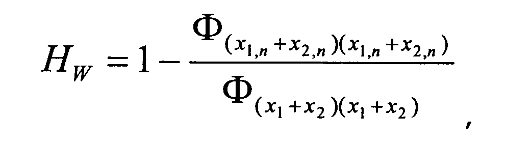
- y 1 is supposed to be a good approximation for x 1, n + x 2, n .
- H W 1 - ⁇ x 1 , n + x 2 , n ⁇ x 1 , n + x 2 , n ⁇ x 1 + x 2 ⁇ x 1 + x 2 ⁇ 1 - ⁇ y 1 ⁇ y 1 ⁇ x 1 + x 2 ⁇ x 1 + x 2 ⁇ 1 + x 2 ⁇ 1 - ⁇ y 1 ⁇ y 1 ⁇ x 1 + x 2 ⁇ x 1 + x 2 ⁇ x 2 .
- both of the left and right microphone signal x 1 , x 2 will be filtered by the same Wiener filter 14 as shown in figure 2 .
- the binaural cues are perfectly preserved not only for the target component but also for the residual of the interfering components.
- the applicability of the proposed scheme was verified by experiments and a prototype of a binaural hearing aid (computer-based real-time demonstrator).
- a two-element microphone array with an inter-element spacing of 20cm was used for the recording.
- Different speech signals of 10 s duration were played from 2-4 loudspeakers with 1.5m distance to the microphones simultaneously.
- the signals were divided into blocks of length 8192 with successive blocks overlapped by a factor of 2. Length of the main BSS filter was 1024.
- the experiments are conducted for 2, 3, 4 active sources individually.
- SIR signal-to-interference ratio
- SDF logarithm of speech-distortion factors
- Table 1 shows the performance of the proposed scheme. It can be seen that the proposed scheme can achieve about 6 dB SIR improvement ( ⁇ SIR) for 2 and 3 active sources and 3 dB SIR improvement for 4 active sources. Moreover, in the sound examples the musical tones and the artifacts can hardly be perceived owing to the combination of the improved interference estimation and corresponding Wiener filtering.
Abstract
- filtering a left and a right microphone signal (x 1 , x 2) by a Wiener filter (14) to obtain binaural output signals (ŝL ,ŝR ) of the target point source (s), where said Wiener filter (14) is calculated as

where Hw is said Wiener filter (14), Φ(x 1,n+ x 2,n )(x 1,n+ x 2,n ) is the auto power spectral density of the sum of all the M interfering point sources components (x1,n, x2,n) contained in the left and right microphone signal (x1, x2) and Φ(x 1+x 2)(x 1+x 2) is the auto power spectral density of
the sum of the left and right microphone signal (x1, x2).
Description
- The present invention relates to a method and an Acoustic Signal Processing System for noise reduction of a binaural microphone signal with one target point source and several interfering point sources as input sources to a left and a right microphone of a binaural microphone system. Specifically, the present invention relates to hearing aids employing such methods and devices.
- In the present document reference will be made to the following documents:
- [BAK05] H. Buchner, R. Aichner, and W. Kellermann. A generalization of blind source separation algorithms for convolutive mixtures based on second-order statistics. IEEE Transactions on Speech and Audio Signal Processing, Jan. 2005.
- [PA02] L.C. Parra and C.V. Alvino. Geometric source separation: Merging convolutive source separation with geometric beamforming. IEEE Transactions on Speech and Audio Processing, 10(6):352{362, Sep. 2002.
- In signal enhancement tasks, adaptive Wiener Filtering is often used to suppress the background noise and interfering sources. For the required interference and noise estimates, several approaches are proposed usually exploiting VAD (Voice Activity Detection), and beam-forming, which uses a microphone array with a known geometry. The drawback of VAD is that the voice-pause cannot be robustly detected, especially in the multi-speaker environment. The beam-former does not rely on the VAD, nevertheless, it needs a priori information about the source positions. As an alternative method, Blind Source Separation (BSS) was proposed to be used in speech enhancement which overcomes the drawbacks mentioned and drastically reduces the number of microphones. However, the limitation of BSS is that the number of point sources cannot be larger than the number of microphones, or else BSS is not capable to separate the sources.
- It is the object of the present invention to provide a method and an acoustic signal processing system for improving interference estimation in binaural Wiener Filtering in order to effectively suppress background noise and interfering sources.
- According to the present invention the above objective is fulfilled by a method for noise reduction of a binaural microphone signal. One target point source and M interfering point sources are input sources to a left and a right microphone of a binaural microphone system. The method comprises the following step:
- filtering a left and a right microphone signal by a Wiener filter to obtain binaural output signals of the target point source, where the Wiener filter is calculated as

- According to a preferred embodiment the sum of all the M interfering point sources components contained in the left and right microphone signal is approximated by an output of a Blind Source Separation system with the left and right microphone signal as input signals.
- Preferably, said Blind Source Separation comprises a Directional Blind Source Separation Algorithm and a Shadow Blind Source Separation algorithm.
- Furthermore, the present invention foresees an acoustic signal processing system comprising a binaural microphone system with a left and a right microphone and a Wiener filter unit for noise reduction of a binaural microphone signal with one target point source and M interfering point sources as input sources to the left and the right microphone. The Wiener filter unit is calculated as
where Φ(x 1,n +x 2,n )(x 1,n +x 2,n ) is the auto power spectral density of the sum of all the M interfering point sources components contained in the left and right microphone signal and Φ(x 1+x 2)(x 1+x 2) is the auto power spectral density of the sum of the left and right microphone signal, and the left microphone signal of the left microphone and the right microphone signal of the right microphone are filtered by said Wiener filter to obtain binaural output signals of the target point source. - According to a preferred embodiment the acoustic signal processing system comprises a Blind Source Separation unit,
where the sum of all the M interfering point source components contained in the left and right microphone signal is approximated by an output of said Blind Source Separation unit with the left and right microphone signal as input signals. - Furthermore, said Blind Source Separation unit comprises a Directional Blind Source Separation unit and a Shadow Blind Source Separation unit.
- Finally, the left and right microphone of the acoustic signal processing system are located in different hearing aids.
- More specialties and benefits of the present invention are explained in more detail by means of schematic drawings showing in:
-
Figure 1 : a hearing aid according to the state of the art and -
Figure 2 : a block diagram of the considered acoustic scenario and the signal processing system. - Since the present application is preferably applicable to hearing aids, such devices shall be briefly introduced in the next two paragraphs together with
figure 1 . - Hearing aids are wearable hearing devices used for supplying hearing impaired persons. In order to comply with the numerous individual needs, different types of hearing aids, like behind-the-ear hearing aids and in-the-ear hearing aids, e.g. concha hearing aids or hearing aids completely in the canal, are provided. The hearing aids listed above as examples are worn at or behind the external ear or within the auditory canal. Furthermore, the market also provides bone conduction hearing aids, implantable or vibrotactile hearing aids. In these cases the affected hearing is stimulated either mechanically or electrically.
- In principle, hearing aids have one or more input transducers, an amplifier and an output transducer as essential component. An input transducer usually is an acoustic receiver, e.g. a microphone, and/or an electromagnetic receiver, e.g. an induction coil. The output transducer normally is an electro-acoustic transducer like a miniature speaker or an electro-mechanical transducer like a bone conduction transducer. The amplifier usually is integrated into a signal processing unit. Such principle structure is shown in
figure 1 for the example of a behind-the-ear hearing aid. One ormore microphones 2 for receiving sound from the surroundings are installed in a hearing aid housing 1 for wearing behind the ear. A signal processing unit 3 being also installed in the hearing aid housing 1 processes and amplifies the signals from the microphone. The output signal of the signal processing unit 3 is transmitted to a receiver 4 for outputting an acoustical signal. Optionally, the sound will be transmitted to the ear drum of the hearing aid user via a sound tube fixed with an otoplastic in the auditory canal. The hearing aid and specifically the signal processing unit 3 are supplied with electrical power by abattery 5 also installed in the hearing aid housing 1. - In a preferred embodiment of the invention two hearing aids, one for the left ear and one for the right ear, have to be used ("binaural supply"). The two hearing aids can communicate which each other in order to exchange microphone data.
- If the left and right hearing aid include more than one microphone any preprocessing that combines the microphone signals to a single signal in each hearing aid can use the invention.
-
Figure 2 shows the proposed scheme which is composed of three major components A, B, C. The first component A is the linear BSS model in the underdetermined scenario when more point sources s, n1, n2, ..., nM thanmicrophones 2 are present. Directional BSS 11 is exploited to estimate the interfering point sources n1, n2, ..., nM as the second component B. Its major advantage is that it can deal with the underdetermined scenario. In the third component C, the estimated interference y1 is used to calculate a time-varying Wienerfilter 14 and then the binaural enhanced target signal ŝ can be obtained by filtering the binaural microphone signals x1, x2 with the calculated Wienerfilter 14. Owing to the linear-phase property of the calculatedWiener filter 14, original signal-phase-based binaural cues are perfectly preserved not only for the target source s but also for the residual interfering sources n1, n2, ... nM. Especially the application to hearing aids can benefit from this property. In the following, a detailed description of the individual components and experimental results will be presented. - As illustrated in
Figure 2 , one target point source s and M interfering point sources nm , m = 1,...,M are filtered by a linear multiple-input-multiple-output (MIMO)system 10 before they are picked up by twomicrophones 2. Thus, the microphone signals x 1, x 2 can be described in the discrete-time domain by:
where "*" represents convolution, hlj , l = 1,...,M+1, j = 1, 2 denotes the FIR filter model from the 1-th source to the j-th microphone. x 1, x 2 denote the left and right microphone signal for use as a binaural microphone signal. Note that here the original sources s, n1, n2, ..., nM are assumed to be point sources so that the signal paths can be modeled by FIR filters. In the following, for simplicity, the time argument k for all signals in the time domain is omitted and time-domain signals are represented by lower-case letters. - BSS B is desired to find a corresponding demixing system W to extract the individual sources from the mixed signals. The output signals of the demixing system yi (k), i = 1, 2 are described by:

where wji denotes the demixing filter from the j-th microphone to the i-th output channel. - There are different criteria for convolutive source separation proposed. They are all based on the assumption that the sources are statistically independent and can all be used for the said invention, although with different effectiveness. In the proposed scheme, the "TRINICON" criterion for second-order statistics [BAK05] is used as the BSS optimization criterion, where the cost function JBSS (W) aims at reducing the off-diagonal elements of the correlation matrix of the two BSS outputs:

- For l=j=2, in each output channel one source can be suppressed by a spatial null. Nevertheless, for the underdetermined scenario no unique solution can be achieved. However, here we exploit a new application of BSS, i.e, its function as a blocking matrix to generate an interference estimate. This can be done by using the Directional BSS 11,
where a spatial null can be forced to a certain direction for assuring that the source coming from this direction is suppressed well after Directional BSS 11. - The basic theory for Directional BSS 11 is described in [PA02], where the given demixing matrix is:

wT i = [w 1i w2i ] (i = 1, 2) includes the demixing filter for the i-th BSS-output channel and is regarded as a beam-former, whose response can be constrained to a particular orientation θ, which denotes the target source location and is assumed to be known in [PA02]. In the proposed scheme, we design a "blind" Directional BSS B, where θ is not a priori known, but can be detected from aShadow BSS 12 algorithm as described in the next section. To explain the algorithm, the angle θ is supposed to be given. The algorithm for a two-microphone setup is derived as follows:
For a two-element linear array with omni-directional sensors and a far-field source, the array response depends only on the angle θ = θ (q) between the source and the axis of the linear array:
where d(q) represents the phases and magnitude responses of the sensors for a source located at q. p is the vector of the sensor position of the linear array and c is the sound propagation speed. - The total response for the BSS-output channel i is given by:

- Constraining the response to an angle θ is expressed by:

- The geometric constraint C is introduced into the cost function:

where
- The cost function can be simplified by the following conditions:
- 1. Only one BSS output channel should be controlled by the geometric constraint. Without loss of generality the output channel 1 is set to be the controlled channel. Hence, wT 2d(θ)is set to be zero such that only w T 1, not w T 2 is influenced by JC (W).
- 2. In [PA02], the geometric constraint is suggested to be C = I, where I is the identity matrix, which indicates emphasizing the target source located at the direction of θ and attenuating other sources. In the proposed scheme, the target source should be suppressed like in a null-steering beam-forming, i.e. a spatial null is forced to the direction of the target source. Hence, here the geometric constraint C is equal to the zero-matrix.
- Thus, the cost function JC (W) is simplified to be:

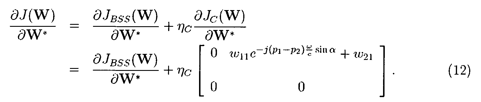
- Moreover, the BSS cost function JBSS (W) will be expanded by the cost function JC (W) with the weight η C :

- Here, the weight η C is selected to be a constant, typically in the range of [0.4, ..., 0.6] and indicates how important JC (W) is. By forming the gradient of the cost function J(W) with respect to the demixing filter w* j,i we can obtain the gradient update for W:

- Using

- In the previous section, the angular position θ of the target source is assumed to be known a prior. But in practice, this information is unknown. In order to ascertain that the target source is active and to obtain the geometric information of the target source, a method of 'peak' detection is used to detect the source activity and position which will be described in the following:
- Usually, the BSS adaptation enhances one peak (spatial null) in each BSS channel such that one source is suppressed by exactly one spatial null, where the position of the peak can be used for the source localization. Based on this observation, if a source in a defined angular range is active, a peak must appear in the corresponding range of the demixing filter impulse responses. Hence, supposing that only one possibly active source in the target angular range exists, we can detect the source activity by searching the peak in the range and compare this peak with a defined threshold to indicate whether the target source is active or not. Meanwhile, the position of the peak can be converted to the angular information of the target source. However, once the BSS B is controlled by the geometric constraint, the peak will always be forced into the position corresponding to the angle θ, even if the target source moves from θ to another position. In order to detect the source location fast and reliably, a
shadow BSS 12 without geometric constraint running in parallel to the main Directional BSS 11 is introduced, which is designed to react fast to varying source movement by virtue of its short filter length and periodical re-initialization. As shown infigure 2 theShadow BSS 12 detects the movement of the target source and gives its current position to the Directional BSS 11. In this way, the Directional BSS 11 can apply the geometric constraint according to the given θ and follows the target source movement. - In the underdetermined scenario for a two-microphone setup, one target point source s and M interfering point sources nm , m = 1,...,M are passed through the mixing matrix. The microphone signals are given by equation (1) and the BSS output signals are given by equation (2). By applying Directional BSS 11, the target source s is well suppressed in one output, e.g. y 1. Thus, the output y 1 of the Directional BSS 11 can be approximated by:

where xj,n (j = 1, 2) denotes the sum of all the interfering components contained in the j-th microphone. If we take a closer look at y 1 ≈ ω11 * x1,n + ω21 * x 2,n, actually, it can be regarded as a sum of the filtered version the interfering components contained in the microphone signals. Thus, we consider such a Wiener filter, where the input signal is the sum of two microphone signals x 1 + x 2, the desired signal is the sum of the target source components contained in two microphone signals x 1,s + x 2,s . - Assuming that all sources are statistically independent, in the frequency domain, the Wiener filter can be calculated as follows:

where the frequency argument Ω is omitted, φ xy denotes the cross power spectral density (PSD) between x and y, and x 1,n + x2,n denotes the sum of all the interfering components contained in two microphone signals. As mentioned above, y 1 is regarded as a sum of the filtered versions of the interfering components contained in the microphone signals. Thus, y 1 is supposed to be a good approximation for x 1,n + x 2,n . In our proposed scheme, we use y1 as the interference estimate to calculate the Wiener filter and approximate x 1,n + x 2,n by y 1 :
- Furthermore, to obtain the binaural outputs of the target source ŝ=[ŝL,ŝR ] both of the left and right microphone signal x1, x 2 will be filtered by the
same Wiener filter 14 as shown infigure 2 . Owing to the linear-phase property of HW, in ŝ the binaural cues are perfectly preserved not only for the target component but also for the residual of the interfering components. - The applicability of the proposed scheme was verified by experiments and a prototype of a binaural hearing aid (computer-based real-time demonstrator). The experiments have been conducted using speech data convolved with the impulse responses of two real rooms with T 60 = 50, 400 ms respectively and a sampling frequency of fs = 16 kHz. A two-element microphone array with an inter-element spacing of 20cm was used for the recording. Different speech signals of 10 s duration were played from 2-4 loudspeakers with 1.5m distance to the microphones simultaneously. The signals were divided into blocks of length 8192 with successive blocks overlapped by a factor of 2. Length of the main BSS filter was 1024. The experiments are conducted for 2, 3, 4 active sources individually.
- To evaluate the performance, the signal-to-interference ratio (SIR) and the logarithm of speech-distortion factors (SDF)

Table 1: Comparison of SDF and ΔSIR for 2, 3, 4 active sources in two different rooms (measured in dB) number of the sources 2 3 4 anechoic room SIR_In 5.89 -0.67 -2.36 T 60=50ms SDF -14.55 -7.12 -6.64 ΔSIR 6.29 6.33 3.05 reverberant room SIR_In 5.09 -0.85 -2.48 T 60=400ms SDF -13.60 -5.94 -6.23 ΔSIR 6.13 5.29 3.58 - Table 1 shows the performance of the proposed scheme. It can be seen that the proposed scheme can achieve about 6 dB SIR improvement (ΔSIR) for 2 and 3 active sources and 3 dB SIR improvement for 4 active sources. Moreover, in the sound examples the musical tones and the artifacts can hardly be perceived owing to the combination of the improved interference estimation and corresponding Wiener filtering.
Owing to the linear-phase property of the calculated Wiener filter H W, original binaural cues based on signal phase differences are perfectly preserved not only for the target source but also for the residual interfering sources.
Claims (7)
- A method for noise reduction of a binaural microphone signal (x1 , x2 ) with one target point source (s) and M interfering point sources (n1, n2,...,nM) as input sources to a left and a right microphone (2) of a binaural microphone system, comprising the step of:- filtering a left and a right microphone signal (x1, x2 ) by a Wiener filter (14) to obtain binaural output signals (ŝL,ŝR ) of the target point source (s), where said Wiener filter (14) is calculated aswhere HW is said Wiener filter (14), Φ(x 1,n +x 2,n )(x 1,n +x 2,n ) is the auto power spectral density of the sum of all the M interfering point sources components (x 1,n , x 2,n ) contained in the left and right microphone signal (x1, x2 ) and Φ(x 1+x 2)(x 1+x 2) is the auto power spectral density of the sum of the left and right microphone signal (x1, x2 ).

- A method as claimed in claim 1 where the sum of all the M interfering point sources components (x1,n, x2,n ) contained in the left and right microphone signal (x1 , x2 ) is approximated by the output (y1) of a Blind Source Separation (B) with the left and right microphone signal (x1, x2 ) as input signals.
- A method as claimed in claim 1 or claim 2, whereas said Blind Source Separation (B) comprises a Directional Blind Source Separation (11) algorithm and a Shadow Blind Source Separation (12) algorithm.
- Acoustic Signal Processing System comprising a binaural microphone system with a left and a right microphone (2) and a Wiener filter unit (14) for noise reduction of a binaural microphone signal (x1, x2 ) with one target point source (s) and M interfering point sources (n1, n2, ..., nM) as input sources to the left and the right microphone (2), whereas:- the algorithm of said Wiener filter unit (14) is calculated aswhere Φ(x 1,n +x 2,n )(x 1,n +x 2,n ) is the auto power spectral density of the sum of all the M interfering point sources components (x1,n , x2,n ) contained in the left and right microphone signal (x 1, x 2) and Φ(x 1+x 2)(x 1+x 2) is the auto power spectral density of the sum of the left and right microphone signal (x1, x2), and
 - the left microphone signal (x1) of the left microphone (2) and the right microphone signal (x2) of the right microphone (2) are filtered by said Wiener filter unit (14) to obtain binaural output signals (ŝL,ŝR ) of the target point source (s).
 - An acoustic signal processing system as claimed in claim 4 with a Blind Source Separation unit (B), whereas the sum of all the M interfering point sources components (x 1,n, x2,n ) contained in the left and right microphone signal (x1, x2 ) is approximated by an output (y1) of the Blind Source Separation unit (B) with the left and right microphone signal (x1 , x2 ) as input signals.
- An acoustic signal processing system as claimed in claim 5, whereas said Blind Source Separation unit (B) comprises a Directional Blind Source Separation unit (11) and a Shadow Blind Source Separation unit (12).
- An acoustic signal processing system as claimed in one of the claims 4 to 6, whereas the left and right microphone are located in different hearing aids.
Priority Applications (3)
| Application Number | Priority Date | Filing Date | Title |
|---|---|---|---|
| DK09000799.8T DK2211563T3 (en) | 2009-01-21 | 2009-01-21 | Blind source separation method and apparatus for improving interference estimation by binaural Weiner filtration |
| EP09000799A EP2211563B1 (en) | 2009-01-21 | 2009-01-21 | Method and apparatus for blind source separation improving interference estimation in binaural Wiener filtering |
| US12/691,015 US8290189B2 (en) | 2009-01-21 | 2010-01-21 | Blind source separation method and acoustic signal processing system for improving interference estimation in binaural wiener filtering |
Applications Claiming Priority (1)
| Application Number | Priority Date | Filing Date | Title |
|---|---|---|---|
| EP09000799A EP2211563B1 (en) | 2009-01-21 | 2009-01-21 | Method and apparatus for blind source separation improving interference estimation in binaural Wiener filtering |
Publications (2)
| Publication Number | Publication Date |
|---|---|
| EP2211563A1 true EP2211563A1 (en) | 2010-07-28 |
| EP2211563B1 EP2211563B1 (en) | 2011-08-24 |
Family
ID=40578026
Family Applications (1)
| Application Number | Title | Priority Date | Filing Date |
|---|---|---|---|
| EP09000799A Not-in-force EP2211563B1 (en) | 2009-01-21 | 2009-01-21 | Method and apparatus for blind source separation improving interference estimation in binaural Wiener filtering |
Country Status (3)
| Country | Link |
|---|---|
| US (1) | US8290189B2 (en) |
| EP (1) | EP2211563B1 (en) |
| DK (1) | DK2211563T3 (en) |
Cited By (1)
| Publication number | Priority date | Publication date | Assignee | Title |
|---|---|---|---|---|
| DE102013207161A1 (en) | 2013-04-19 | 2014-11-06 | Friedrich-Alexander-Universität Erlangen - Nürnberg | Method for use signal adaptation in binaural hearing aid systems |
Families Citing this family (13)
| Publication number | Priority date | Publication date | Assignee | Title |
|---|---|---|---|---|
| DK2234415T3 (en) * | 2009-03-24 | 2012-02-13 | Siemens Medical Instr Pte Ltd | Method and acoustic signal processing system for binaural noise reduction |
| US9100734B2 (en) | 2010-10-22 | 2015-08-04 | Qualcomm Incorporated | Systems, methods, apparatus, and computer-readable media for far-field multi-source tracking and separation |
| US9037458B2 (en) | 2011-02-23 | 2015-05-19 | Qualcomm Incorporated | Systems, methods, apparatus, and computer-readable media for spatially selective audio augmentation |
| CN102903368B (en) | 2011-07-29 | 2017-04-12 | 杜比实验室特许公司 | Method and equipment for separating convoluted blind sources |
| US9185499B2 (en) * | 2012-07-06 | 2015-11-10 | Gn Resound A/S | Binaural hearing aid with frequency unmasking |
| EP2974084B1 (en) | 2013-03-12 | 2020-08-05 | Hear Ip Pty Ltd | A noise reduction method and system |
| EP2866475A1 (en) | 2013-10-23 | 2015-04-29 | Thomson Licensing | Method for and apparatus for decoding an audio soundfield representation for audio playback using 2D setups |
| CA2953619A1 (en) | 2014-06-05 | 2015-12-10 | Interdev Technologies Inc. | Systems and methods of interpreting speech data |
| US9949041B2 (en) | 2014-08-12 | 2018-04-17 | Starkey Laboratories, Inc. | Hearing assistance device with beamformer optimized using a priori spatial information |
| US10789949B2 (en) * | 2017-06-20 | 2020-09-29 | Bose Corporation | Audio device with wakeup word detection |
| CN111435598B (en) * | 2019-01-15 | 2023-08-18 | 北京地平线机器人技术研发有限公司 | Voice signal processing method, device, computer readable medium and electronic equipment |
| US11380312B1 (en) * | 2019-06-20 | 2022-07-05 | Amazon Technologies, Inc. | Residual echo suppression for keyword detection |
| WO2021161437A1 (en) * | 2020-02-13 | 2021-08-19 | 日本電信電話株式会社 | Sound source separation device, sound source separation method, and program |
Citations (3)
| Publication number | Priority date | Publication date | Assignee | Title |
|---|---|---|---|---|
| US20060120535A1 (en) | 2004-11-08 | 2006-06-08 | Henning Puder | Method and acoustic system for generating stereo signals for each of separate sound sources |
| US20070021958A1 (en) * | 2005-07-22 | 2007-01-25 | Erik Visser | Robust separation of speech signals in a noisy environment |
| WO2007128825A1 (en) * | 2006-05-10 | 2007-11-15 | Phonak Ag | Hearing system and method implementing binaural noise reduction preserving interaural transfer functions |
Family Cites Families (3)
| Publication number | Priority date | Publication date | Assignee | Title |
|---|---|---|---|---|
| US7171008B2 (en) * | 2002-02-05 | 2007-01-30 | Mh Acoustics, Llc | Reducing noise in audio systems |
| US8660281B2 (en) * | 2009-02-03 | 2014-02-25 | University Of Ottawa | Method and system for a multi-microphone noise reduction |
| DK2234415T3 (en) * | 2009-03-24 | 2012-02-13 | Siemens Medical Instr Pte Ltd | Method and acoustic signal processing system for binaural noise reduction |
-
2009
- 2009-01-21 DK DK09000799.8T patent/DK2211563T3/en active
- 2009-01-21 EP EP09000799A patent/EP2211563B1/en not_active Not-in-force
-
2010
- 2010-01-21 US US12/691,015 patent/US8290189B2/en not_active Expired - Fee Related
Patent Citations (3)
| Publication number | Priority date | Publication date | Assignee | Title |
|---|---|---|---|---|
| US20060120535A1 (en) | 2004-11-08 | 2006-06-08 | Henning Puder | Method and acoustic system for generating stereo signals for each of separate sound sources |
| US20070021958A1 (en) * | 2005-07-22 | 2007-01-25 | Erik Visser | Robust separation of speech signals in a noisy environment |
| WO2007128825A1 (en) * | 2006-05-10 | 2007-11-15 | Phonak Ag | Hearing system and method implementing binaural noise reduction preserving interaural transfer functions |
Non-Patent Citations (2)
| Title |
|---|
| VISSER E; TE-WON LEE: "Speech enhancement using blind source separation and two-channel energy based speaker detection", PROCEEDINGS OF INTERNATIONAL CONFERENCE ON ACOUSTICS, SPEECH AND SIGNAL PROCESSING (ICASSP'03) 6-10 APRIL 2003 HONG KONG, CHINA, vol. 1, 6 April 2003 (2003-04-06), 2003 IEEE International Conference on Acoustics, Speech, and Signal Processing (Cat. No.03CH37404) IEEE Piscataway, NJ, USA, pages I-884 - I-887, XP002526938, ISBN: 0-7803-7663-3 * |
| YU TAKAHASHI ET AL: "Blind Source Extraction for Hands-Free Speech Recognition Based on Wiener Filtering and ICA-Based Noise Estimation", HANDS-FREE SPEECH COMMUNICATION AND MICROPHONE ARRAYS, 2008. HSCMA 2008, IEEE, PISCATAWAY, NJ, USA, 6 May 2008 (2008-05-06), pages 164 - 167, XP031269772, ISBN: 978-1-4244-2337-8 * |
Cited By (4)
| Publication number | Priority date | Publication date | Assignee | Title |
|---|---|---|---|---|
| DE102013207161A1 (en) | 2013-04-19 | 2014-11-06 | Friedrich-Alexander-Universität Erlangen - Nürnberg | Method for use signal adaptation in binaural hearing aid systems |
| EP2802158A2 (en) | 2013-04-19 | 2014-11-12 | Siemens Medical Instruments Pte. Ltd. | Method for adapting useful signals in binaural hearing assistance systems |
| US9277333B2 (en) | 2013-04-19 | 2016-03-01 | Sivantos Pte. Ltd. | Method for adjusting the useful signal in binaural hearing aid systems and hearing aid system |
| DE102013207161B4 (en) | 2013-04-19 | 2019-03-21 | Sivantos Pte. Ltd. | Method for use signal adaptation in binaural hearing aid systems |
Also Published As
| Publication number | Publication date |
|---|---|
| US8290189B2 (en) | 2012-10-16 |
| US20100183178A1 (en) | 2010-07-22 |
| EP2211563B1 (en) | 2011-08-24 |
| DK2211563T3 (en) | 2011-12-19 |
Similar Documents
| Publication | Publication Date | Title |
|---|---|---|
| EP2211563B1 (en) | Method and apparatus for blind source separation improving interference estimation in binaural Wiener filtering | |
| US10431239B2 (en) | Hearing system | |
| EP1509065B1 (en) | Method for processing audio-signals | |
| EP2916321B1 (en) | Processing of a noisy audio signal to estimate target and noise spectral variances | |
| Hadad et al. | The binaural LCMV beamformer and its performance analysis | |
| CN107071674B (en) | Hearing device and hearing system configured to locate a sound source | |
| EP3267697A1 (en) | Direction of arrival estimation in miniature devices using a sound sensor array | |
| EP3704874B1 (en) | Method of operating a hearing aid system and a hearing aid system | |
| US8358796B2 (en) | Method and acoustic signal processing system for binaural noise reduction | |
| Yousefian et al. | A dual-microphone algorithm that can cope with competing-talker scenarios | |
| CN101754081A (en) | Improvements in hearing aid algorithms | |
| EP2876900A1 (en) | Spatial filter bank for hearing system | |
| US20150043742A1 (en) | Hearing device with input transducer and wireless receiver | |
| Kokkinakis et al. | Multi-microphone adaptive noise reduction strategies for coordinated stimulation in bilateral cochlear implant devices | |
| Reindl et al. | Analysis of two generic wiener filtering concepts for binaural speech enhancement in hearing aids | |
| Marquardt et al. | Noise power spectral density estimation for binaural noise reduction exploiting direction of arrival estimates | |
| Kokkinakis et al. | Using blind source separation techniques to improve speech recognition in bilateral cochlear implant patients | |
| Klasen et al. | Preservation of interaural time delay for binaural hearing aids through multi-channel Wiener filtering based noise reduction | |
| Farmani et al. | Sound source localization for hearing aid applications using wireless microphones | |
| EP3148217B1 (en) | Method for operating a binaural hearing system | |
| US9736599B2 (en) | Method for evaluating a useful signal and audio device | |
| D'Olne et al. | Model-based beamforming for wearable microphone arrays | |
| Kokkinakis et al. | Advances in modern blind signal separation algorithms: theory and applications | |
| Abraham et al. | Current Strategies for Noise Reduction in Hearing Aids-A Review. | |
| Schmitz et al. | On the reduction of masking effects while preserving competing binaural audio streams |
Legal Events
| Date | Code | Title | Description |
|---|---|---|---|
| PUAI | Public reference made under article 153(3) epc to a published international application that has entered the european phase |
Free format text: ORIGINAL CODE: 0009012 |
|
| 17P | Request for examination filed |
Effective date: 20090619 |
|
| AK | Designated contracting states |
Kind code of ref document: A1 Designated state(s): AT BE BG CH CY CZ DE DK EE ES FI FR GB GR HR HU IE IS IT LI LT LU LV MC MK MT NL NO PL PT RO SE SI SK TR |
|
| AX | Request for extension of the european patent |
Extension state: AL BA RS |
|
| GRAP | Despatch of communication of intention to grant a patent |
Free format text: ORIGINAL CODE: EPIDOSNIGR1 |
|
| RTI1 | Title (correction) |
Free format text: METHOD AND APPARATUS FOR BLIND SOURCE SEPARATION IMPROVING INTERFERENCE ESTIMATION IN BINAURAL WIENER FILTERING |
|
| AKX | Designation fees paid |
Designated state(s): CH DE DK FR GB LI |
|
| RAP1 | Party data changed (applicant data changed or rights of an application transferred) |
Owner name: SIEMENS MEDICAL INSTRUMENTS PTE. LTD. |
|
| GRAS | Grant fee paid |
Free format text: ORIGINAL CODE: EPIDOSNIGR3 |
|
| GRAA | (expected) grant |
Free format text: ORIGINAL CODE: 0009210 |
|
| AK | Designated contracting states |
Kind code of ref document: B1 Designated state(s): CH DE DK FR GB LI |
|
| REG | Reference to a national code |
Ref country code: GB Ref legal event code: FG4D |
|
| REG | Reference to a national code |
Ref country code: CH Ref legal event code: NV Representative=s name: SIEMENS SCHWEIZ AG Ref country code: CH Ref legal event code: EP |
|
| REG | Reference to a national code |
Ref country code: DE Ref legal event code: R096 Ref document number: 602009002216 Country of ref document: DE Effective date: 20111027 |
|
| REG | Reference to a national code |
Ref country code: DK Ref legal event code: T3 |
|
| PLBE | No opposition filed within time limit |
Free format text: ORIGINAL CODE: 0009261 |
|
| STAA | Information on the status of an ep patent application or granted ep patent |
Free format text: STATUS: NO OPPOSITION FILED WITHIN TIME LIMIT |
|
| 26N | No opposition filed |
Effective date: 20120525 |
|
| REG | Reference to a national code |
Ref country code: DE Ref legal event code: R097 Ref document number: 602009002216 Country of ref document: DE Effective date: 20120525 |
|
| REG | Reference to a national code |
Ref country code: DE Ref legal event code: R082 Ref document number: 602009002216 Country of ref document: DE Representative=s name: FDST PATENTANWAELTE FREIER DOERR STAMMLER TSCH, DE |
|
| REG | Reference to a national code |
Ref country code: DE Ref legal event code: R082 Ref document number: 602009002216 Country of ref document: DE Representative=s name: FDST PATENTANWAELTE FREIER DOERR STAMMLER TSCH, DE |
|
| REG | Reference to a national code |
Ref country code: DE Ref legal event code: R082 Ref document number: 602009002216 Country of ref document: DE Representative=s name: FDST PATENTANWAELTE FREIER DOERR STAMMLER TSCH, DE Ref country code: DE Ref legal event code: R081 Ref document number: 602009002216 Country of ref document: DE Owner name: SIVANTOS PTE. LTD., SG Free format text: FORMER OWNER: SIEMENS MEDICAL INSTRUMENTS PTE. LTD., SINGAPORE, SG |
|
| REG | Reference to a national code |
Ref country code: FR Ref legal event code: PLFP Year of fee payment: 8 |
|
| REG | Reference to a national code |
Ref country code: FR Ref legal event code: PLFP Year of fee payment: 9 |
|
| REG | Reference to a national code |
Ref country code: FR Ref legal event code: PLFP Year of fee payment: 10 |
|
| PGFP | Annual fee paid to national office [announced via postgrant information from national office to epo] |
Ref country code: CH Payment date: 20190124 Year of fee payment: 11 Ref country code: FR Payment date: 20190123 Year of fee payment: 11 Ref country code: GB Payment date: 20190124 Year of fee payment: 11 Ref country code: DE Payment date: 20190124 Year of fee payment: 11 |
|
| PGFP | Annual fee paid to national office [announced via postgrant information from national office to epo] |
Ref country code: DK Payment date: 20190124 Year of fee payment: 11 |
|
| REG | Reference to a national code |
Ref country code: DE Ref legal event code: R119 Ref document number: 602009002216 Country of ref document: DE |
|
| REG | Reference to a national code |
Ref country code: DK Ref legal event code: EBP Effective date: 20200131 Ref country code: CH Ref legal event code: PL |
|
| GBPC | Gb: european patent ceased through non-payment of renewal fee |
Effective date: 20200121 |
|
| PG25 | Lapsed in a contracting state [announced via postgrant information from national office to epo] |
Ref country code: DE Free format text: LAPSE BECAUSE OF NON-PAYMENT OF DUE FEES Effective date: 20200801 Ref country code: GB Free format text: LAPSE BECAUSE OF NON-PAYMENT OF DUE FEES Effective date: 20200121 Ref country code: FR Free format text: LAPSE BECAUSE OF NON-PAYMENT OF DUE FEES Effective date: 20200131 |
|
| PG25 | Lapsed in a contracting state [announced via postgrant information from national office to epo] |
Ref country code: CH Free format text: LAPSE BECAUSE OF NON-PAYMENT OF DUE FEES Effective date: 20200131 Ref country code: LI Free format text: LAPSE BECAUSE OF NON-PAYMENT OF DUE FEES Effective date: 20200131 |
|
| PG25 | Lapsed in a contracting state [announced via postgrant information from national office to epo] |
Ref country code: DK Free format text: LAPSE BECAUSE OF NON-PAYMENT OF DUE FEES Effective date: 20200131 |