EP2211766B1 - Retrieval catheter - Google Patents
Retrieval catheter Download PDFInfo
- Publication number
- EP2211766B1 EP2211766B1 EP08834878.4A EP08834878A EP2211766B1 EP 2211766 B1 EP2211766 B1 EP 2211766B1 EP 08834878 A EP08834878 A EP 08834878A EP 2211766 B1 EP2211766 B1 EP 2211766B1
- Authority
- EP
- European Patent Office
- Prior art keywords
- dilator
- sheath
- component
- tubular
- distal end
- Prior art date
- Legal status (The legal status is an assumption and is not a legal conclusion. Google has not performed a legal analysis and makes no representation as to the accuracy of the status listed.)
- Active
Links
- 238000000034 method Methods 0.000 description 20
- 230000002792 vascular Effects 0.000 description 18
- 210000005166 vasculature Anatomy 0.000 description 13
- 239000011248 coating agent Substances 0.000 description 10
- 238000000576 coating method Methods 0.000 description 10
- 229920002614 Polyether block amide Polymers 0.000 description 7
- 239000003550 marker Substances 0.000 description 7
- 239000000463 material Substances 0.000 description 7
- 229920001343 polytetrafluoroethylene Polymers 0.000 description 7
- 230000003902 lesion Effects 0.000 description 6
- 229910052751 metal Inorganic materials 0.000 description 6
- 239000002184 metal Substances 0.000 description 6
- 239000004810 polytetrafluoroethylene Substances 0.000 description 6
- 229920001169 thermoplastic Polymers 0.000 description 6
- 239000004416 thermosoftening plastic Substances 0.000 description 6
- 230000003073 embolic effect Effects 0.000 description 5
- -1 polyethylene Polymers 0.000 description 5
- 238000001356 surgical procedure Methods 0.000 description 5
- 229910001220 stainless steel Inorganic materials 0.000 description 4
- 239000000853 adhesive Substances 0.000 description 3
- 230000001070 adhesive effect Effects 0.000 description 3
- 238000011065 in-situ storage Methods 0.000 description 3
- 239000000314 lubricant Substances 0.000 description 3
- 239000000049 pigment Substances 0.000 description 3
- 229920000642 polymer Polymers 0.000 description 3
- 238000011084 recovery Methods 0.000 description 3
- 239000010935 stainless steel Substances 0.000 description 3
- 231100000216 vascular lesion Toxicity 0.000 description 3
- 208000031481 Pathologic Constriction Diseases 0.000 description 2
- 239000004698 Polyethylene Substances 0.000 description 2
- 239000004642 Polyimide Substances 0.000 description 2
- 229920000249 biocompatible polymer Polymers 0.000 description 2
- 239000000919 ceramic Substances 0.000 description 2
- 238000010276 construction Methods 0.000 description 2
- 238000003780 insertion Methods 0.000 description 2
- 230000037431 insertion Effects 0.000 description 2
- 238000012986 modification Methods 0.000 description 2
- 230000004048 modification Effects 0.000 description 2
- HLXZNVUGXRDIFK-UHFFFAOYSA-N nickel titanium Chemical compound [Ti].[Ti].[Ti].[Ti].[Ti].[Ti].[Ti].[Ti].[Ti].[Ti].[Ti].[Ni].[Ni].[Ni].[Ni].[Ni].[Ni].[Ni].[Ni].[Ni].[Ni].[Ni].[Ni].[Ni].[Ni] HLXZNVUGXRDIFK-UHFFFAOYSA-N 0.000 description 2
- 229910001000 nickel titanium Inorganic materials 0.000 description 2
- 239000004033 plastic Substances 0.000 description 2
- 229920003023 plastic Polymers 0.000 description 2
- BASFCYQUMIYNBI-UHFFFAOYSA-N platinum Chemical compound [Pt] BASFCYQUMIYNBI-UHFFFAOYSA-N 0.000 description 2
- 229920000573 polyethylene Polymers 0.000 description 2
- 229920001721 polyimide Polymers 0.000 description 2
- 230000036262 stenosis Effects 0.000 description 2
- 208000037804 stenosis Diseases 0.000 description 2
- 238000009966 trimming Methods 0.000 description 2
- 206010061660 Artery dissection Diseases 0.000 description 1
- 208000032843 Hemorrhage Diseases 0.000 description 1
- 239000004677 Nylon Substances 0.000 description 1
- 239000004743 Polypropylene Substances 0.000 description 1
- 208000027418 Wounds and injury Diseases 0.000 description 1
- 230000003466 anti-cipated effect Effects 0.000 description 1
- 208000007474 aortic aneurysm Diseases 0.000 description 1
- 210000004204 blood vessel Anatomy 0.000 description 1
- MTAZNLWOLGHBHU-UHFFFAOYSA-N butadiene-styrene rubber Chemical compound C=CC=C.C=CC1=CC=CC=C1 MTAZNLWOLGHBHU-UHFFFAOYSA-N 0.000 description 1
- 238000013172 carotid endarterectomy Methods 0.000 description 1
- 238000004891 communication Methods 0.000 description 1
- 239000002131 composite material Substances 0.000 description 1
- 210000004351 coronary vessel Anatomy 0.000 description 1
- 238000013461 design Methods 0.000 description 1
- 230000010102 embolization Effects 0.000 description 1
- 238000000605 extraction Methods 0.000 description 1
- 210000001105 femoral artery Anatomy 0.000 description 1
- PCHJSUWPFVWCPO-UHFFFAOYSA-N gold Chemical compound [Au] PCHJSUWPFVWCPO-UHFFFAOYSA-N 0.000 description 1
- 239000010931 gold Substances 0.000 description 1
- 229910052737 gold Inorganic materials 0.000 description 1
- 210000004013 groin Anatomy 0.000 description 1
- 230000023597 hemostasis Effects 0.000 description 1
- 208000014674 injury Diseases 0.000 description 1
- 238000013152 interventional procedure Methods 0.000 description 1
- 229910052741 iridium Inorganic materials 0.000 description 1
- GKOZUEZYRPOHIO-UHFFFAOYSA-N iridium atom Chemical compound [Ir] GKOZUEZYRPOHIO-UHFFFAOYSA-N 0.000 description 1
- 150000002739 metals Chemical class 0.000 description 1
- 208000010125 myocardial infarction Diseases 0.000 description 1
- 208000031225 myocardial ischemia Diseases 0.000 description 1
- 229920001778 nylon Polymers 0.000 description 1
- 229920001558 organosilicon polymer Polymers 0.000 description 1
- 230000002093 peripheral effect Effects 0.000 description 1
- 229910052697 platinum Inorganic materials 0.000 description 1
- 229920003229 poly(methyl methacrylate) Polymers 0.000 description 1
- 229920002401 polyacrylamide Polymers 0.000 description 1
- 229920000515 polycarbonate Polymers 0.000 description 1
- 239000004417 polycarbonate Substances 0.000 description 1
- 239000004926 polymethyl methacrylate Substances 0.000 description 1
- 229920006324 polyoxymethylene Polymers 0.000 description 1
- 229920001155 polypropylene Polymers 0.000 description 1
- 229920002635 polyurethane Polymers 0.000 description 1
- 239000004814 polyurethane Substances 0.000 description 1
- 239000004800 polyvinyl chloride Substances 0.000 description 1
- 229920000915 polyvinyl chloride Polymers 0.000 description 1
- 230000001681 protective effect Effects 0.000 description 1
- 230000000250 revascularization Effects 0.000 description 1
- 230000007704 transition Effects 0.000 description 1
- 230000008733 trauma Effects 0.000 description 1
Images


Classifications
-
- A—HUMAN NECESSITIES
- A61—MEDICAL OR VETERINARY SCIENCE; HYGIENE
- A61F—FILTERS IMPLANTABLE INTO BLOOD VESSELS; PROSTHESES; DEVICES PROVIDING PATENCY TO, OR PREVENTING COLLAPSING OF, TUBULAR STRUCTURES OF THE BODY, e.g. STENTS; ORTHOPAEDIC, NURSING OR CONTRACEPTIVE DEVICES; FOMENTATION; TREATMENT OR PROTECTION OF EYES OR EARS; BANDAGES, DRESSINGS OR ABSORBENT PADS; FIRST-AID KITS
- A61F2/00—Filters implantable into blood vessels; Prostheses, i.e. artificial substitutes or replacements for parts of the body; Appliances for connecting them with the body; Devices providing patency to, or preventing collapsing of, tubular structures of the body, e.g. stents
- A61F2/01—Filters implantable into blood vessels
- A61F2/013—Distal protection devices, i.e. devices placed distally in combination with another endovascular procedure, e.g. angioplasty or stenting
-
- A—HUMAN NECESSITIES
- A61—MEDICAL OR VETERINARY SCIENCE; HYGIENE
- A61F—FILTERS IMPLANTABLE INTO BLOOD VESSELS; PROSTHESES; DEVICES PROVIDING PATENCY TO, OR PREVENTING COLLAPSING OF, TUBULAR STRUCTURES OF THE BODY, e.g. STENTS; ORTHOPAEDIC, NURSING OR CONTRACEPTIVE DEVICES; FOMENTATION; TREATMENT OR PROTECTION OF EYES OR EARS; BANDAGES, DRESSINGS OR ABSORBENT PADS; FIRST-AID KITS
- A61F2/00—Filters implantable into blood vessels; Prostheses, i.e. artificial substitutes or replacements for parts of the body; Appliances for connecting them with the body; Devices providing patency to, or preventing collapsing of, tubular structures of the body, e.g. stents
- A61F2/01—Filters implantable into blood vessels
- A61F2/011—Instruments for their placement or removal
-
- A—HUMAN NECESSITIES
- A61—MEDICAL OR VETERINARY SCIENCE; HYGIENE
- A61F—FILTERS IMPLANTABLE INTO BLOOD VESSELS; PROSTHESES; DEVICES PROVIDING PATENCY TO, OR PREVENTING COLLAPSING OF, TUBULAR STRUCTURES OF THE BODY, e.g. STENTS; ORTHOPAEDIC, NURSING OR CONTRACEPTIVE DEVICES; FOMENTATION; TREATMENT OR PROTECTION OF EYES OR EARS; BANDAGES, DRESSINGS OR ABSORBENT PADS; FIRST-AID KITS
- A61F2/00—Filters implantable into blood vessels; Prostheses, i.e. artificial substitutes or replacements for parts of the body; Appliances for connecting them with the body; Devices providing patency to, or preventing collapsing of, tubular structures of the body, e.g. stents
- A61F2/95—Instruments specially adapted for placement or removal of stents or stent-grafts
- A61F2/958—Inflatable balloons for placing stents or stent-grafts
-
- A—HUMAN NECESSITIES
- A61—MEDICAL OR VETERINARY SCIENCE; HYGIENE
- A61B—DIAGNOSIS; SURGERY; IDENTIFICATION
- A61B17/00—Surgical instruments, devices or methods, e.g. tourniquets
- A61B17/22—Implements for squeezing-off ulcers or the like on the inside of inner organs of the body; Implements for scraping-out cavities of body organs, e.g. bones; Calculus removers; Calculus smashing apparatus; Apparatus for removing obstructions in blood vessels, not otherwise provided for
- A61B2017/22038—Implements for squeezing-off ulcers or the like on the inside of inner organs of the body; Implements for scraping-out cavities of body organs, e.g. bones; Calculus removers; Calculus smashing apparatus; Apparatus for removing obstructions in blood vessels, not otherwise provided for with a guide wire
- A61B2017/22039—Implements for squeezing-off ulcers or the like on the inside of inner organs of the body; Implements for scraping-out cavities of body organs, e.g. bones; Calculus removers; Calculus smashing apparatus; Apparatus for removing obstructions in blood vessels, not otherwise provided for with a guide wire eccentric
-
- A—HUMAN NECESSITIES
- A61—MEDICAL OR VETERINARY SCIENCE; HYGIENE
- A61F—FILTERS IMPLANTABLE INTO BLOOD VESSELS; PROSTHESES; DEVICES PROVIDING PATENCY TO, OR PREVENTING COLLAPSING OF, TUBULAR STRUCTURES OF THE BODY, e.g. STENTS; ORTHOPAEDIC, NURSING OR CONTRACEPTIVE DEVICES; FOMENTATION; TREATMENT OR PROTECTION OF EYES OR EARS; BANDAGES, DRESSINGS OR ABSORBENT PADS; FIRST-AID KITS
- A61F2/00—Filters implantable into blood vessels; Prostheses, i.e. artificial substitutes or replacements for parts of the body; Appliances for connecting them with the body; Devices providing patency to, or preventing collapsing of, tubular structures of the body, e.g. stents
- A61F2/95—Instruments specially adapted for placement or removal of stents or stent-grafts
- A61F2002/9528—Instruments specially adapted for placement or removal of stents or stent-grafts for retrieval of stents
-
- A—HUMAN NECESSITIES
- A61—MEDICAL OR VETERINARY SCIENCE; HYGIENE
- A61F—FILTERS IMPLANTABLE INTO BLOOD VESSELS; PROSTHESES; DEVICES PROVIDING PATENCY TO, OR PREVENTING COLLAPSING OF, TUBULAR STRUCTURES OF THE BODY, e.g. STENTS; ORTHOPAEDIC, NURSING OR CONTRACEPTIVE DEVICES; FOMENTATION; TREATMENT OR PROTECTION OF EYES OR EARS; BANDAGES, DRESSINGS OR ABSORBENT PADS; FIRST-AID KITS
- A61F2/00—Filters implantable into blood vessels; Prostheses, i.e. artificial substitutes or replacements for parts of the body; Appliances for connecting them with the body; Devices providing patency to, or preventing collapsing of, tubular structures of the body, e.g. stents
- A61F2/95—Instruments specially adapted for placement or removal of stents or stent-grafts
- A61F2002/9534—Instruments specially adapted for placement or removal of stents or stent-grafts for repositioning of stents
-
- A—HUMAN NECESSITIES
- A61—MEDICAL OR VETERINARY SCIENCE; HYGIENE
- A61F—FILTERS IMPLANTABLE INTO BLOOD VESSELS; PROSTHESES; DEVICES PROVIDING PATENCY TO, OR PREVENTING COLLAPSING OF, TUBULAR STRUCTURES OF THE BODY, e.g. STENTS; ORTHOPAEDIC, NURSING OR CONTRACEPTIVE DEVICES; FOMENTATION; TREATMENT OR PROTECTION OF EYES OR EARS; BANDAGES, DRESSINGS OR ABSORBENT PADS; FIRST-AID KITS
- A61F2230/00—Geometry of prostheses classified in groups A61F2/00 - A61F2/26 or A61F2/82 or A61F9/00 or A61F11/00 or subgroups thereof
- A61F2230/0002—Two-dimensional shapes, e.g. cross-sections
- A61F2230/0004—Rounded shapes, e.g. with rounded corners
- A61F2230/0006—Rounded shapes, e.g. with rounded corners circular
-
- A—HUMAN NECESSITIES
- A61—MEDICAL OR VETERINARY SCIENCE; HYGIENE
- A61M—DEVICES FOR INTRODUCING MEDIA INTO, OR ONTO, THE BODY; DEVICES FOR TRANSDUCING BODY MEDIA OR FOR TAKING MEDIA FROM THE BODY; DEVICES FOR PRODUCING OR ENDING SLEEP OR STUPOR
- A61M25/00—Catheters; Hollow probes
- A61M25/01—Introducing, guiding, advancing, emplacing or holding catheters
- A61M2025/018—Catheters having a lateral opening for guiding elongated means lateral to the catheter
-
- A—HUMAN NECESSITIES
- A61—MEDICAL OR VETERINARY SCIENCE; HYGIENE
- A61M—DEVICES FOR INTRODUCING MEDIA INTO, OR ONTO, THE BODY; DEVICES FOR TRANSDUCING BODY MEDIA OR FOR TAKING MEDIA FROM THE BODY; DEVICES FOR PRODUCING OR ENDING SLEEP OR STUPOR
- A61M25/00—Catheters; Hollow probes
- A61M25/01—Introducing, guiding, advancing, emplacing or holding catheters
- A61M2025/0183—Rapid exchange or monorail catheters
Definitions
- the present invention relates to catheters used for retrieving, positioning, or repositioning endoluminal devices located distal or adjacent to a stent or other previously implanted device.
- endovascular surgery is rapidly becoming an alternative to more traditional surgeries such as carotid endarterectomy, coronary artery bypass grafting, aortic aneurysm repair, and vascular grafting.
- Percutaneous intervention is becoming the primary means for revascularization in many such procedures.
- Distal embolization of friable debris from within the diseased conduit remains a risk of endovascular surgery, potentially involving complications such as myocardial infarction and ischemia.
- Devices such as balloon catheters and embolic filters have been used to control and remove embolic debris dislodged from arterial walls during endovascular procedures, distal to an interventional procedure site.
- Percutaneous introduction of these devices typically involves access via the femoral artery lumen of the patient's groin vasculature.
- An introducer sheath may then be inserted in the wound, followed by a guide catheter that is advanced to the site to be treated.
- a guidewire is usually introduced into the lumen of the vasculature and advanced distally, via manipulation by the clinician, to cross the lesion or area of treatment.
- a catheter containing the device(s) may be employed to traverse the length of the guidewire to the desired deployment location. Once the distal protection device is deployed, the lesion or stenosis is available for treatment.
- a common practice for treating the lesion or stenosis is to deploy a stent at the target location to increase the lumen size of the vessel and maintain or increase patency.
- a stent When feeding a guidewire through the lumen of a stent, there is a possibility that the tip of the wire will become diverted and/or ensnared by the stent. This possibility increases with increasing vessel tortuosity.
- This problem has been addressed through the use of a soft, flexible, floppy tip at the distal end of the wire to improve steerability and reduce the possibility of engaging the stent or peripheral vasculature.
- a flat-tipped catheter advanced over a guidewire with an inside diameter larger than the outside diameter of the guidewire presents a sharp edge to the vessel or stent at the point of tangential contact.
- the exposure of this edge increases with vessel tortuosity and with an increase in differences between the guidewire outside diameter and catheter inside diameter.
- Embolic filters and balloons are often deployed by traversing the lesion being treated and deploying the device distally. If a balloon wire or embolic filter becomes caught in the patient's vasculature or is otherwise prevented from removal by a stent, such as the device becoming entrapped within the struts of a stent, then the clinician is typically required to perform higher risk procedures to retrieve them. These include subjecting the device to greater retrieval forces, and removal through invasive surgical techniques. The former increases the risk of the device becoming detached from its guidewire or catheter, whereas the latter exposes the patient to the increased risks of open surgical extraction. Successful retrieval of these devices in situations other than those originally anticipated, without intimal dissection, plaque, hemorrhage, or vessel occlusion, is an important advancement in the field of interventional endovascular surgery.
- a recovery catheter in WO2006/091498 , which is considered as the closest prior art, includes an elongate outer catheter and an elongate inner catheter.
- the outer catheter has a generally tubular configuration and includes an inferior or proximal end portion and a superior or distal portion.
- a rapid exchange sideport can be formed along a midsection of the recovery catheter.
- a lumen extends the length of the recovery catheter from its proximal end portion to the distal end portion. The lumen is in communication with the sideport.
- the inner catheter includes an inferior or proximal end portion and a superior or distal end portion.
- the distal end portion of the inner member has a tapered or narrowing profile.
- a lumen extends along a portion of the inner catheter.
- the lumen can extend from the distal end portion of the inner catheter to a transition junction where the lumen curves and exits a sidewall of the inner catheter.
- the exit point can be placed along a midsection of the inner catheter and is arranged to be in alignment with the sideport of the outer catheter to thereby provide a rapid exchange conduit.
- the inner catheter lumen is designed to receive a guide wire of a filter or embolic protection assembly.
- the rapid exchange sideport has a grater longitudinal extent than the exit point of the inner catheter lumen to permit relative longitudinal movement of the inner and outer catheters with a guide wire in situ.
- WO03/068106 discloses a somewhat similar arrangement featuring an inner shaft and an outer sheath featuring an elongate opening.
- a retrieval catheter assembly is described that may be operated by a single clinician and upon delivery will neither permanently displace a previously deployed stent nor cause undue trauma to the vascular lumen or lesion.
- the retrieval catheter assembly will enable a tubular retrieval sheath to be advanced over a wire between the outside diameter of a deployed stent and the vessel wall, or over a guidewire through the lumen of a stent and retrieve various devices, e.g., filters, balloons, etc. distal to the stent.
- the retrieval catheter may also enable a tubular sheath to be directed through the sidewall of a stent.
- a catheter assembly according to claim 1.
- the retrieval catheter assembly comprises a sheath having a balloon wire or guidewire exchange port through the sidewall of the sheath and a dilator, which is positioned in the sheath lumen.
- the sheath has a body with relatively stiff proximal and distal sections and with a flexible middle section, which aids in the operation of the device.
- the dilator is adapted to slide axially relative to the sheath between an extended position and a retracted position while a balloon wire or guidewire extends through the exchange port. When the dilator is withdrawn in a proximal direction into the sheath, it provides a space within the lumen of the distal end of the sheath to accommodate a filter or other device retrieved by the wire.
- the dilator includes a tapered tip, which allows the device to be inserted between the stent and the vasculature for retrieval of devices distal to the stent.
- the tip may be a soft or hard pliable thermoplastic, metal such as stainless steel, or ceramic and will have a radius, which averts snagging on the stent and vasculature.
- the inner diameter of the tip is sized to control the clearance between the tip inner diameter and the guidewire outer diameter, which aids in operation of the device.
- the catheter assembly preferably includes a hydrophilic and/or a lubricious coating applied to the dilator tip and also preferably applied to the sheath from tip to the exchange port.
- this catheter assembly includes a sheath, dilator and guidewire.
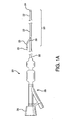
- Figure 1A is a perspective view of catheter assembly 20, having a sheath 22, dilator 24, guidewire threading tube 25, and guidewire 26.
- Guidewire threading tube 25 may be constructed from a variety of polymeric materials such as polyimide.
- Guidewire threading tube 25 is provided to aid in the insertion of the guidewire 26 through sheath slot 30 and dilator slot 46 (per Figure 1 B) , prior to use in a patient.
- This threading tube 25 is typically removed from catheter assembly 20 prior to insertion into a patient.
- Also shown in Figure 1A is the proximal end of the dilator 24, or dilator hub 28 extending from the luer hub 29.
- Figure 1A additionally depicts the distal section 23 of catheter assembly 20.
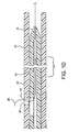
- Figures 1C-1E are longitudinal cross-sections of distal section 23 showing a sheath 22, dilator 24, dilator lumen 27, sheath slot 30, dilator slot 46, and guidewire 26. Note the relative distal movement of sheath 22 and sheath slot 30 with respect to dilator 24 and dilator slot 46.
- the sheath 22 and hubs 28 and 29 may comprise conventional medical grade materials such as nylon, acrylanitrile butadiene styrene, polyacrylamide, polycarbonate, polyethylene, polyformaldehyde, polymethylmethacrylate, polypropylene, polytetrafluoroethylene, polytrifluorochlorethylene, polyether block amide or thermoplastic copolyether, polyvinylchloride, polyurethane, elastomeric organosilicon polymers, and metals such as stainless steels and nitinol.
- the sheath 22 or dilator 24 may contain either radiopaque markers or contain radiopaque materials commonly known in the art.
- the catheter assembly 20 may be used to retrieve a previously placed vascular filter 32.
- Figure 2A illustrates a vascular filter 32 with filter wire 34 placed within the vasculature 36, distal to a lesion 37.
- a stent 38 is placed over the vascular lesion 37 creating a rough, tortuous region across which vascular filter 32 is to be retracted as shown in Figure 2B .
- Figure 2C depicts a retrieval catheter 40 of prior art. Note the relatively inflexible catheter shaft and the inability of the catheter 40 to maintain a concentric position within the lumen of the catheter shaft of filter wire 34. Also note the significant difference between catheter 40 inner diameter and filter wire 34 outer diameter, creating an opening which provides an opportunity for catheter 40 to engage with the stent 38.
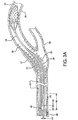
- Figures 3A through 3D show sequential cross-sectional views of the retrieval catheter in use.
- the catheter assembly 20 is used to retrieve a previously placed vascular filter 32.
- Figure 3A illustrates an embodiment of the present retrieval catheter with sheath 22 and dilator 24 navigating the rough, tortuous region through the stent 38 toward the previously placed vascular filter 32.
- the sheath 22 may be constructed with varying stiffness along the length. Methods of construction to achieve variable stiffness in a sheath component are well known in the art and include varying cross sectional profile dimensions and/or wall thickness, changing the hardness or modulus of the sheath material, braid modification, and including the use of a removable stylet or stiffening wire. Additional methods of achieving variable stiffness in a sheath component are generally taught by U.S. Pat. No. 6,858,024 and U.S. Pat. Appl. No. 2007/0088323 A1 .
- the sheath 22 may be made with an outer diameter that would vary depending on targeted vascular size. For example, a sheath used with a 0.36mm guidewire would have an outer diameter that ranges from about 1.57mm to 1.62mm. The sheath 22 inner diameter would also vary with application and for use with a 0.36mm guidewire typically ranges from about 1.22mm to 1.27mm.
- the sheath 22 includes a slot or aperture 30 functioning as a cooperative opening or exchange port through the sidewall of the sheath.
- the slot 30 may be formed through the side wall of the sheath 22 by methods known in the art which may include skiving by hand with a straight razor or cutting with a suitable tool.
- One or both ends of slot 30 may be formed to be perpendicular to the longitudinal axis of sheath 22. Alternately, one or both ends may be formed to have a taper to reduce the angle between the proximal end of slot 30 and the guidewire 26.
- the slot 30 may be a formed to have a length 42 that would vary with application but would preferably range from about 0.20mm to 0.38mm.
- Slot 30 may have a width 44 suitable to provide adequate clearance between the slot 30 and a guidewire 26 or balloon wire.
- slot 30 may be formed as a slit thus providing an interference fit between the guidewire 26 or balloon wire and the slit walls.
- Slot 30 may also be configured with features to provide positive tactile feedback to a user during device use. These may include such features slot 30 being formed to have a barbell shape that provides stops at the proximal and distal ends of slot 30 for securing guidewire 26 or a balloon wire. Slot 30 may also be provided with rough surfaces or serrations along the edge the of slot 30 to provide enhanced tactile feedback.
- the slot 30 may be cut at a distance from the distal end of the sheath from about 1 cm to about 50cm from the distal end of the sheath 22 depending on the specific design requirements.
- the range would be from about 5cm to about 31cm from the distal end of the sheath 22.
- the most preferred range would be from about 25cm to about 32cm from the distal end of the sheath 22.
- the outer surface of sheath 22 may be provided with a hydrophilic/lubricious coating.
- the coating may be applied to the entire outer surface of the sheath. Most preferably, the coating may be applied from the most distal end continuing to about the slot 30 or aperture.
- the inner surface of sheath 22 component may be provided with a hydrophilic/lubricious coating.
- the coating may be applied to the entire inner surface of the sheath 22. Preferably, the coating may be applied to the distal most 40cm of the sheath 22. Most preferably, the coating may be applied to the distal most 30cm of the sheath 22.
- the coating may be any biocompatible polymer lubricant as commonly known in the art.
- Dilator 24 is typically formed from a lubricious plastic material such as polytetraflouroethylene, polyethylene, polyether block amide or thermoplastic copolyether to provide a high degree of lubricity in the blood vessel as well as with respect to movement of the sheath 22 over the dilator 24.
- Dilator 24 may also be formed of a lubricious plastic material in combination with a metal hypo tube.
- Dilator 24 is typically provided with a hub 28 at its proximal end and is of a length slightly greater than the length of the catheter assembly so that when the hub 28 of the dilator is advanced fully distally against the proximal end of catheter hub 29, the tip of dilator 24 will project beyond the distal end of the catheter.
- the length of dilator 24 will depend on the length of the sheath 22.
- the tip of dilator 24 is considered to be the tapered portion located at the distal most tip of dilator 24.
- a length of about 1 cm for the tapered portion will be applicable to most applications but could range from about 1mm to 5cm.
- Dilator 24 may be made with an outer diameter sized to pass through the lumen of the sheath 22 with which it is intended to be and may be supplied in various sizes dependant on the application and catheter sheath inner diameter.
- a typical range of outer diameters for the intended application of retrieving a vascular filter or balloon would be from about 1.14mm to 1.19mm.
- the clearance between a guidewire 26 or balloon wire and the lumen of dilator 24 is relatively small and would vary dependant on intended use.
- a typical inner tip diameter would be from about 0.38mm to 0.43mm.
- dilator 24 may be used with a balloon wire where a typical inner tip diameter would be from about 0.48mm to 0.53mm.
- Dilator 24 has a lumen 27 adapted for passage of a guidewire or balloon wire. Diameters of dilator lumens 27 will vary with intended use. A typical dilator lumen 27, suitable for use with a guidewire 26, would be from about 0.48mm to 0.53mm. Alternately, dilator 24 may be made with a lumen 27 suitable for balloon wires, typically ranging from about 0.61mm to 0.66mm.
- Dilator 24 may have a tip made of pliable thermoplastic such as Pebax ® (polyether block amide or thermoplastic copolyether from Arkema, Beaumont TX 77704) or metal such as stainless steel, nitinol or any other material with appropriate stiffness, hardness and other properties suitable for use in the human body.
- the dilator tip may alternately be constructed of a combination of a biocompatible metal and thermoplastic in a variety of ways.
- the tip may also be of composite metal or ceramic and/or polymer construction.
- dilator 24 has a slot 46 through the sidewall of the dilator 24.
- the dilator slot 46 may be formed through the sidewall of the dilator 24 by methods well known in the art which may include skiving by hand with a straight razor cutting with a suitable tool.
- One or both ends of dilator slot 46 may be formed to be perpendicular to the longitudinal axis of dilator 24. Alternately, one or both ends may be formed to have a taper to reduce the angle between the proximal end of dilator slot 46 and the guidewire 26.
- the dilator slot 46 may have a length 48 extending from about 1cm proximal to the dilator tip to the distal end of the luer hub 29.
- the dilator slot 46 may extend from about 1 cm proximal to the dilator tip to about 100cm proximal to the tip.
- the dilator slot 46 may extend from about 1cm proximal to the dilator tip to about 33cm proximal to the tip.
- dilator slot 46 (particularly if configured as a slit as described below) may extend from the tip to about, for example, 33 cm proximal to the tip.
- Dilator slot 46 may have a width 48 suitable to provide adequate clearance between the dilator slot 46 and a guidewire 26 or balloon wire.
- dilator slot 46 may be formed as a slit thus providing an interference fit between the guidewire 26 or balloon wire and the slit walls.
- Dilator slot 46 may also be configured with features to provide positive tactile feedback to a user during device use. These may include such features dilator slot 46 being formed to have a barbell shape that provides stops at the proximal and distal ends of dilator slot 46 for securing guidewire 26 or a balloon wire. Dilator slot 46 may also be provided with rough surfaces or serrations along the edge the of dilator slot 46 to provide enhanced tactile feedback.
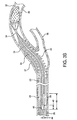
- Figure 3B shows the distal end of the catheter assembly 20 positioned in vasculature 36 in close proximity to a previously placed vascular filter 32.
- the catheter assembly 20 was advanced over the previously placed vascular filter wire 34. Note that dilator 24 protrudes from the sheath 22.
- the dilator 24 is retracted into sheath 22 in the direction as shown by arrow 50. Note the axial sliding movement of slot 30 and dilator slot 46 with respect to slot 30 of sheath 22.
- the dilator 24 remains retracted into the sheath 22.
- Sheath 22 is advanced in the direction as shown by arrow 52 thereby collapsing the vascular filter 32.
- the catheter assembly 20 is withdrawn from the target site.
- Figures 4A through 4C show sequential cross-sectional views of a retrieval catheter in use retrieving a balloon 54.
- Figure 4A shows a stent 38 deployed over a balloon 54 and balloon wire 56, trapping the balloon 54 and/or balloon wire 56 between the stent 38 and vasculature 36.
- Figure 4B depicts a retrieval catheter 40 of prior art. Note the relatively inflexible catheter shaft and the inability of the catheter 40 to maintain a concentric position within the lumen of the catheter shaft of balloon wire 56.
- Figure 4C illustrates an embodiment of the invention with sheath 22 and dilator 24 navigating the rough tortuous region between the stent 38 and the vasculature 36 toward the trapped balloon 54.
- the remainder of the balloon retrieval procedure is similar to the procedure described in Figures 3B through 3D .
- the present invention may also be used to position or reposition a device located distal or adjacent to a stent or other previously implanted device.
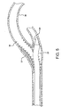
- Figure 5 depicts an embodiment of the present invention with sheath 22 and dilator 24 exiting the lumen of a previously placed stent 38 through the sidewall of the stent 38.
- This embodiment could be used to deploy or reposition an endoluminal device into the branch vasculature.
- the same embodiment could alternately be used to retrieve an endoluminal device from branch vasculature.
- a 1.24mm PTFE coated mandrel was loaded with a 1.29mm inner diameter etched PTFE liner (1.29mm inner diameter. x 0.02mm thick wall) and secured.
- a braided sleeving (0.25mm x 0.76mm stainless steel flat wire, 2 over 2 under, 50 ppi) was loaded and secured at the proximal end of mandrel.
- the braid was stretched to the distal end of the mandrel and carefully trimmed to length with scissors so that the ends of the wires were uniform. Trimming of the braid length may be achieved with any suitable cutting or trimming tool.
- a marker band (platinum/iridium, 1mm width minimum, inner diameter 14.7mm, 0.25mm minimum thickness) was slid onto the assembly from the proximal end of the loaded mandrel to the distal end.
- the marker band was carefully brought up to the end of the braid so that the marker band covered the end of the braid and so that no ends of wires were showing at the marker band.
- the location of the marker band should be from about 5.08cm to 6.35cm from the distal end of the mandrel.
- a hand crimper tool was used to secure the marker band.
- the braid was then stretched from the proximal end of the mandrel and re-secured.
- the proximal component (Pebax ® 7233, 72 durometer and 1.57mm inner diameter and 0.10mm wall, gold pigment) was cut to about 125cm and the distal body stock component (Pebax ® 5533 , 55 durometer and 0.157cm inner diameter and 0.10mm wall, grey pigment) was cut to about 32.5cm.
- the distal body stock component was flared with the end of a pair of small tweezers so that it would slide over the proximal body stock component.
- the distal and proximal components were loaded onto a 0.15mm PTFE mandrel (nonporous PTFE) and the two components were overlapped by 1mm.
- a 2.54cm long length of FEP heat shrink (EP4587-10T, Zeus, Orangeburg, SC 29116) was positioned over the center of the 1 mm overlap of the two body stock components and a heat gun was used to bond the two components together.
- the FEP heat shrink tube was removed after the bond had cooled.
- the pre-assembled body stock component was loaded onto the proximal end of the 1.24mm PTFE coated mandrel bringing the end of the pre-assembled body stock component to within 2cm to 3cm past the marker band.
- a heat shrink tube (EP4587-10T FEP 1.9mm minimum expanded inner diameter) was loaded over the entire assembly with the end of the heat shrink tube reaching the end of the pre-assembled body stock component distal end. The two ends were bonded together with a heat gun. The assembly was heated in a convection heat shrink reflow oven. The assembly was allowed to air cool, the heat shrink tube was removed and the ends were trimmed with a razor. The entire assembly was removed from the mandrel.
- the assembly was cut to a length of about 142cm and the tip was trimmed. A hole was hand cut at about 29.7cm from the distal end of the sheath.
- a female luer hub (Qosina part No. 41426 Qosina, Edgewood, NY 11717) was bonded to the proximal end with adhesive (Loctite® 4011 Adhesive, Henkel Corp., Rocky Hill, CT 06067).
- a stock dilator (Pebax ® 7233, light grey pigment, 0.48mm inner diameter x 0.12mm outer diameter) was tipped down to 0.36mm inner diameter and 0.66mm outer diameter with a radio frequency tipping machine (Ameritherm Inc., Scottsville, NY 14546). The dilator was then cut to about 152cm in length. Any appropriate cutting method may be used. An 4.0cm slot was hand skived in the dilator starting at about 27.2cm from the distal end of the dilator. The proximal end of the dilator was heat flared to form a mechanical anchor. A female luer hub (Qosina part .No. 64018) was bonded onto the dilator proximal end with Loctite® 3311 Adhesive.
- a hemostasis valve (part No. RV0317-000, Qosina part No. 88416) was attached to the hub of the dilator 24.
- guidewire threading tube 25 (Phelps Dodge part No. Polyimide EP4649-10Z 0.38mm inner diameter x 0.47mm outer diameter, Phelps Dodge HPC, Trenton, GA 30752) was installed in the assembly.
- the catheter assembly 20 was masked to expose the proximal and distal ends.
- a flexible mandrel (0.46mm outer diameter) was inserted into the distal end of the assembly until it exited the cooperative opening 30.
- the loaded assembly was then placed into a vacuum plasma system.
- the entire assembly was plasma treated to enhance attachment of the polymer lubricant.
- the catheter assembly 20 was removed from plasma system.
- the sheath 22 and dilator 24 components of the catheter assembly 20 were then dip coated with a biocompatible polymer lubricant to reduce friction.
- the catheter assembly 20 with lubricious coating was then heat cured.
- the flexible mandrel was removed and catheter assembly 20 was then placed in a protective polymer coil and packaged for shipment.
Description
- The present invention relates to catheters used for retrieving, positioning, or repositioning endoluminal devices located distal or adjacent to a stent or other previously implanted device.
- The field of endovascular surgery is rapidly becoming an alternative to more traditional surgeries such as carotid endarterectomy, coronary artery bypass grafting, aortic aneurysm repair, and vascular grafting. Percutaneous intervention is becoming the primary means for revascularization in many such procedures. Distal embolization of friable debris from within the diseased conduit remains a risk of endovascular surgery, potentially involving complications such as myocardial infarction and ischemia. Devices such as balloon catheters and embolic filters have been used to control and remove embolic debris dislodged from arterial walls during endovascular procedures, distal to an interventional procedure site. Percutaneous introduction of these devices typically involves access via the femoral artery lumen of the patient's groin vasculature. An introducer sheath may then be inserted in the wound, followed by a guide catheter that is advanced to the site to be treated. A guidewire is usually introduced into the lumen of the vasculature and advanced distally, via manipulation by the clinician, to cross the lesion or area of treatment. Then a catheter containing the device(s) may be employed to traverse the length of the guidewire to the desired deployment location. Once the distal protection device is deployed, the lesion or stenosis is available for treatment.
- A common practice for treating the lesion or stenosis is to deploy a stent at the target location to increase the lumen size of the vessel and maintain or increase patency. When feeding a guidewire through the lumen of a stent, there is a possibility that the tip of the wire will become diverted and/or ensnared by the stent. This possibility increases with increasing vessel tortuosity. This problem has been addressed through the use of a soft, flexible, floppy tip at the distal end of the wire to improve steerability and reduce the possibility of engaging the stent or peripheral vasculature. However, a flat-tipped catheter advanced over a guidewire with an inside diameter larger than the outside diameter of the guidewire, presents a sharp edge to the vessel or stent at the point of tangential contact. The exposure of this edge increases with vessel tortuosity and with an increase in differences between the guidewire outside diameter and catheter inside diameter.
- Embolic filters and balloons are often deployed by traversing the lesion being treated and deploying the device distally. If a balloon wire or embolic filter becomes caught in the patient's vasculature or is otherwise prevented from removal by a stent, such as the device becoming entrapped within the struts of a stent, then the clinician is typically required to perform higher risk procedures to retrieve them. These include subjecting the device to greater retrieval forces, and removal through invasive surgical techniques. The former increases the risk of the device becoming detached from its guidewire or catheter, whereas the latter exposes the patient to the increased risks of open surgical extraction. Successful retrieval of these devices in situations other than those originally anticipated, without intimal dissection, plaque, hemorrhage, or vessel occlusion, is an important advancement in the field of interventional endovascular surgery.
- In
WO2006/091498 , which is considered as the closest prior art, a recovery catheter includes an elongate outer catheter and an elongate inner catheter. The outer catheter has a generally tubular configuration and includes an inferior or proximal end portion and a superior or distal portion. Along a midsection of the recovery catheter, a rapid exchange sideport can be formed. A lumen extends the length of the recovery catheter from its proximal end portion to the distal end portion. The lumen is in communication with the sideport. - The inner catheter includes an inferior or proximal end portion and a superior or distal end portion. The distal end portion of the inner member has a tapered or narrowing profile.
- A lumen extends along a portion of the inner catheter. The lumen can extend from the distal end portion of the inner catheter to a transition junction where the lumen curves and exits a sidewall of the inner catheter. The exit point can be placed along a midsection of the inner catheter and is arranged to be in alignment with the sideport of the outer catheter to thereby provide a rapid exchange conduit.
- The inner catheter lumen is designed to receive a guide wire of a filter or embolic protection assembly.
- The rapid exchange sideport has a grater longitudinal extent than the exit point of the inner catheter lumen to permit relative longitudinal movement of the inner and outer catheters with a guide wire in situ.
-
WO03/068106 - A retrieval catheter assembly is described that may be operated by a single clinician and upon delivery will neither permanently displace a previously deployed stent nor cause undue trauma to the vascular lumen or lesion. The retrieval catheter assembly will enable a tubular retrieval sheath to be advanced over a wire between the outside diameter of a deployed stent and the vessel wall, or over a guidewire through the lumen of a stent and retrieve various devices, e.g., filters, balloons, etc. distal to the stent. The retrieval catheter may also enable a tubular sheath to be directed through the sidewall of a stent.
- According to a first aspect of the present invention there is provided a catheter assembly according to claim 1.
- The retrieval catheter assembly comprises a sheath having a balloon wire or guidewire exchange port through the sidewall of the sheath and a dilator, which is positioned in the sheath lumen. The sheath has a body with relatively stiff proximal and distal sections and with a flexible middle section, which aids in the operation of the device. The dilator is adapted to slide axially relative to the sheath between an extended position and a retracted position while a balloon wire or guidewire extends through the exchange port. When the dilator is withdrawn in a proximal direction into the sheath, it provides a space within the lumen of the distal end of the sheath to accommodate a filter or other device retrieved by the wire.
- The dilator includes a tapered tip, which allows the device to be inserted between the stent and the vasculature for retrieval of devices distal to the stent. The tip may be a soft or hard pliable thermoplastic, metal such as stainless steel, or ceramic and will have a radius, which averts snagging on the stent and vasculature. The inner diameter of the tip is sized to control the clearance between the tip inner diameter and the guidewire outer diameter, which aids in operation of the device.
- The catheter assembly preferably includes a hydrophilic and/or a lubricious coating applied to the dilator tip and also preferably applied to the sheath from tip to the exchange port.
-
-
Figure 1A is a perspective view of the catheter assembly. -
Figure 1B is a longitudinal cross-sectional view of the catheter assembly tip with guidewire threading tube. -
Figure 1C is a longitudinal cross-sectional view of the catheter assembly tip and relative position of the cooperative opening region during a first stage of device retrieval. -
Figure 1D is a longitudinal cross-sectional view of the catheter assembly tip and relative position of the cooperative opening region during a second stage of device retrieval. -
Figure 1E is a longitudinal cross-sectional view of the catheter assembly tip configured to have a slit type cooperative opening extending to the most distal tip of the assembly. -
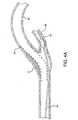
Figure 2A is a cross-sectional view of a vascular filter in situ, distal to a vascular lesion. -
Figure 2B is a cross-sectional view of a vascular filter in situ, distal to a vascular lesion that has been covered by a deployed stent. -
Figure 2C is a cross-sectional view of a retrieval catheter of prior art. -
Figure 3A is a cross-sectional view of one embodiment of this invention showing a step in a method of using the retrieval device in a vascular filter retrieval procedure. -
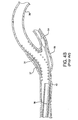
Figure 3B is a cross-sectional view of one embodiment of this invention showing a second step in a method of using the retrieval device in a vascular filter retrieval procedure. -
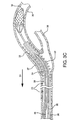
Figure 3C is a cross-sectional view of one embodiment of this invention showing a third step in a method of using the retrieval device in a vascular filter retrieval procedure. -
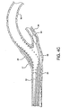
Figure 3D is a cross-sectional view of one embodiment of this invention showing a fourth step in a method of using the retrieval device in a vascular filter retrieval procedure. -
Figure 4A is a cross-sectional view of an occlusion balloon with the balloon wire positioned between the deployed stent and the vasculature. -
Figure 4B is a cross-sectional view of a retrieval catheter of prior art. -
Figure 4C is a cross-sectional view of one embodiment of the present retrieval catheter showing a step in a method of using the retrieval device in a balloon retrieval procedure. -
Figure 5 is perspective view of one embodiment of the present retrieval catheter showing the retrieval catheter exiting the lumen of a previously placed stent through the sidewall of the stent. - As noted above, this catheter assembly includes a sheath, dilator and guidewire.
Figure 1A is a perspective view ofcatheter assembly 20, having asheath 22,dilator 24,guidewire threading tube 25, and guidewire 26.Guidewire threading tube 25 may be constructed from a variety of polymeric materials such as polyimide.Guidewire threading tube 25 is provided to aid in the insertion of theguidewire 26 throughsheath slot 30 and dilator slot 46 (perFigure 1 B) , prior to use in a patient. This threadingtube 25 is typically removed fromcatheter assembly 20 prior to insertion into a patient. Also shown inFigure 1A is the proximal end of thedilator 24, ordilator hub 28 extending from theluer hub 29. -
Figure 1A additionally depicts thedistal section 23 ofcatheter assembly 20.Figures 1C-1E are longitudinal cross-sections ofdistal section 23 showing asheath 22,dilator 24, dilator lumen 27,sheath slot 30,dilator slot 46, and guidewire 26. Note the relative distal movement ofsheath 22 andsheath slot 30 with respect todilator 24 anddilator slot 46. Thesheath 22 andhubs sheath 22 ordilator 24 may contain either radiopaque markers or contain radiopaque materials commonly known in the art. - In one embodiment, the
catheter assembly 20 may be used to retrieve a previously placedvascular filter 32.Figure 2A illustrates avascular filter 32 withfilter wire 34 placed within thevasculature 36, distal to alesion 37. In this application, astent 38 is placed over thevascular lesion 37 creating a rough, tortuous region across whichvascular filter 32 is to be retracted as shown inFigure 2B .Figure 2C depicts aretrieval catheter 40 of prior art. Note the relatively inflexible catheter shaft and the inability of thecatheter 40 to maintain a concentric position within the lumen of the catheter shaft offilter wire 34. Also note the significant difference betweencatheter 40 inner diameter andfilter wire 34 outer diameter, creating an opening which provides an opportunity forcatheter 40 to engage with thestent 38. -
Figures 3A through 3D show sequential cross-sectional views of the retrieval catheter in use. In these figures, thecatheter assembly 20 is used to retrieve a previously placedvascular filter 32. -
Figure 3A illustrates an embodiment of the present retrieval catheter withsheath 22 anddilator 24 navigating the rough, tortuous region through thestent 38 toward the previously placedvascular filter 32. Thesheath 22 may be constructed with varying stiffness along the length. Methods of construction to achieve variable stiffness in a sheath component are well known in the art and include varying cross sectional profile dimensions and/or wall thickness, changing the hardness or modulus of the sheath material, braid modification, and including the use of a removable stylet or stiffening wire. Additional methods of achieving variable stiffness in a sheath component are generally taught byU.S. Pat. No. 6,858,024 andU.S. Pat. Appl. No. 2007/0088323 A1 . Thesheath 22 may be made with an outer diameter that would vary depending on targeted vascular size. For example, a sheath used with a 0.36mm guidewire would have an outer diameter that ranges from about 1.57mm to 1.62mm. Thesheath 22 inner diameter would also vary with application and for use with a 0.36mm guidewire typically ranges from about 1.22mm to 1.27mm. - The
sheath 22 includes a slot oraperture 30 functioning as a cooperative opening or exchange port through the sidewall of the sheath. Theslot 30 may be formed through the side wall of thesheath 22 by methods known in the art which may include skiving by hand with a straight razor or cutting with a suitable tool. One or both ends ofslot 30 may be formed to be perpendicular to the longitudinal axis ofsheath 22. Alternately, one or both ends may be formed to have a taper to reduce the angle between the proximal end ofslot 30 and theguidewire 26. As shown inFigure 3A , theslot 30 may be a formed to have alength 42 that would vary with application but would preferably range from about 0.20mm to 0.38mm.Slot 30 may have awidth 44 suitable to provide adequate clearance between theslot 30 and aguidewire 26 or balloon wire. Alternately, slot 30 may be formed as a slit thus providing an interference fit between the guidewire 26 or balloon wire and the slit walls.Slot 30 may also be configured with features to provide positive tactile feedback to a user during device use. These may includesuch features slot 30 being formed to have a barbell shape that provides stops at the proximal and distal ends ofslot 30 for securingguidewire 26 or a balloon wire.Slot 30 may also be provided with rough surfaces or serrations along the edge the ofslot 30 to provide enhanced tactile feedback. Theslot 30 may be cut at a distance from the distal end of the sheath from about 1 cm to about 50cm from the distal end of thesheath 22 depending on the specific design requirements. Preferably, the range would be from about 5cm to about 31cm from the distal end of thesheath 22. The most preferred range would be from about 25cm to about 32cm from the distal end of thesheath 22. - The outer surface of
sheath 22 may be provided with a hydrophilic/lubricious coating. The coating may be applied to the entire outer surface of the sheath. Most preferably, the coating may be applied from the most distal end continuing to about theslot 30 or aperture. The inner surface ofsheath 22 component may be provided with a hydrophilic/lubricious coating. The coating may be applied to the entire inner surface of thesheath 22. Preferably, the coating may be applied to the distal most 40cm of thesheath 22. Most preferably, the coating may be applied to the distal most 30cm of thesheath 22. The coating may be any biocompatible polymer lubricant as commonly known in the art. -
Dilator 24 is typically formed from a lubricious plastic material such as polytetraflouroethylene, polyethylene, polyether block amide or thermoplastic copolyether to provide a high degree of lubricity in the blood vessel as well as with respect to movement of thesheath 22 over thedilator 24.Dilator 24 may also be formed of a lubricious plastic material in combination with a metal hypo tube.Dilator 24 is typically provided with ahub 28 at its proximal end and is of a length slightly greater than the length of the catheter assembly so that when thehub 28 of the dilator is advanced fully distally against the proximal end ofcatheter hub 29, the tip ofdilator 24 will project beyond the distal end of the catheter. Thus, the length ofdilator 24 will depend on the length of thesheath 22. The tip ofdilator 24 is considered to be the tapered portion located at the distal most tip ofdilator 24. A length of about 1 cm for the tapered portion will be applicable to most applications but could range from about 1mm to 5cm. -
Dilator 24 may be made with an outer diameter sized to pass through the lumen of thesheath 22 with which it is intended to be and may be supplied in various sizes dependant on the application and catheter sheath inner diameter. A typical range of outer diameters for the intended application of retrieving a vascular filter or balloon would be from about 1.14mm to 1.19mm. The clearance between a guidewire 26 or balloon wire and the lumen ofdilator 24 is relatively small and would vary dependant on intended use. For the intended application involving use over a guidewire, a typical inner tip diameter would be from about 0.38mm to 0.43mm. Alternately,dilator 24 may be used with a balloon wire where a typical inner tip diameter would be from about 0.48mm to 0.53mm.Dilator 24 has a lumen 27 adapted for passage of a guidewire or balloon wire. Diameters of dilator lumens 27 will vary with intended use. A typical dilator lumen 27, suitable for use with aguidewire 26, would be from about 0.48mm to 0.53mm. Alternately,dilator 24 may be made with a lumen 27 suitable for balloon wires, typically ranging from about 0.61mm to 0.66mm. -
Dilator 24 may have a tip made of pliable thermoplastic such as Pebax® (polyether block amide or thermoplastic copolyether from Arkema, Beaumont TX 77704) or metal such as stainless steel, nitinol or any other material with appropriate stiffness, hardness and other properties suitable for use in the human body. The dilator tip may alternately be constructed of a combination of a biocompatible metal and thermoplastic in a variety of ways. The tip may also be of composite metal or ceramic and/or polymer construction. - As shown in
Figure 3A (and similar to theslot 30 through the sidewall of sheath 22),dilator 24 has aslot 46 through the sidewall of thedilator 24. Thedilator slot 46 may be formed through the sidewall of thedilator 24 by methods well known in the art which may include skiving by hand with a straight razor cutting with a suitable tool. One or both ends ofdilator slot 46 may be formed to be perpendicular to the longitudinal axis ofdilator 24. Alternately, one or both ends may be formed to have a taper to reduce the angle between the proximal end ofdilator slot 46 and theguidewire 26. - The
dilator slot 46 may have alength 48 extending from about 1cm proximal to the dilator tip to the distal end of theluer hub 29. Preferably, thedilator slot 46 may extend from about 1 cm proximal to the dilator tip to about 100cm proximal to the tip. Most preferably, thedilator slot 46 may extend from about 1cm proximal to the dilator tip to about 33cm proximal to the tip. In still another embodiment, dilator slot 46 (particularly if configured as a slit as described below) may extend from the tip to about, for example, 33 cm proximal to the tip. -
Dilator slot 46 may have awidth 48 suitable to provide adequate clearance between thedilator slot 46 and aguidewire 26 or balloon wire. Alternately,dilator slot 46 may be formed as a slit thus providing an interference fit between the guidewire 26 or balloon wire and the slit walls.Dilator slot 46 may also be configured with features to provide positive tactile feedback to a user during device use. These may include suchfeatures dilator slot 46 being formed to have a barbell shape that provides stops at the proximal and distal ends ofdilator slot 46 for securingguidewire 26 or a balloon wire.Dilator slot 46 may also be provided with rough surfaces or serrations along the edge the ofdilator slot 46 to provide enhanced tactile feedback. -
Figure 3B shows the distal end of thecatheter assembly 20 positioned invasculature 36 in close proximity to a previously placedvascular filter 32. Thecatheter assembly 20 was advanced over the previously placedvascular filter wire 34. Note thatdilator 24 protrudes from thesheath 22. - As shown in
Figure 3C , thedilator 24 is retracted intosheath 22 in the direction as shown byarrow 50. Note the axial sliding movement ofslot 30 anddilator slot 46 with respect to slot 30 ofsheath 22. - As shown in
Figure 3D , thedilator 24 remains retracted into thesheath 22.Sheath 22 is advanced in the direction as shown byarrow 52 thereby collapsing thevascular filter 32. After thefilter 32 has been collapsed and contained within thesheath 22, thecatheter assembly 20 is withdrawn from the target site. -
Figures 4A through 4C show sequential cross-sectional views of a retrieval catheter in use retrieving aballoon 54. -
Figure 4A shows astent 38 deployed over aballoon 54 andballoon wire 56, trapping theballoon 54 and/orballoon wire 56 between thestent 38 andvasculature 36. -
Figure 4B depicts aretrieval catheter 40 of prior art. Note the relatively inflexible catheter shaft and the inability of thecatheter 40 to maintain a concentric position within the lumen of the catheter shaft ofballoon wire 56. -
Figure 4C illustrates an embodiment of the invention withsheath 22 anddilator 24 navigating the rough tortuous region between thestent 38 and thevasculature 36 toward the trappedballoon 54. The remainder of the balloon retrieval procedure is similar to the procedure described inFigures 3B through 3D . - The present invention may also be used to position or reposition a device located distal or adjacent to a stent or other previously implanted device.
Figure 5 depicts an embodiment of the present invention withsheath 22 anddilator 24 exiting the lumen of a previously placedstent 38 through the sidewall of thestent 38. This embodiment could be used to deploy or reposition an endoluminal device into the branch vasculature. The same embodiment could alternately be used to retrieve an endoluminal device from branch vasculature. - To construct a sheath, a 1.24mm PTFE coated mandrel was loaded with a 1.29mm inner diameter etched PTFE liner (1.29mm inner diameter. x 0.02mm thick wall) and secured. A braided sleeving (0.25mm x 0.76mm stainless steel flat wire, 2 over 2 under, 50 ppi) was loaded and secured at the proximal end of mandrel. The braid was stretched to the distal end of the mandrel and carefully trimmed to length with scissors so that the ends of the wires were uniform. Trimming of the braid length may be achieved with any suitable cutting or trimming tool. A marker band (platinum/iridium, 1mm width minimum, inner diameter 14.7mm, 0.25mm minimum thickness) was slid onto the assembly from the proximal end of the loaded mandrel to the distal end. The marker band was carefully brought up to the end of the braid so that the marker band covered the end of the braid and so that no ends of wires were showing at the marker band. The location of the marker band should be from about 5.08cm to 6.35cm from the distal end of the mandrel. A hand crimper tool was used to secure the marker band. The braid was then stretched from the proximal end of the mandrel and re-secured.
- To pre-assemble the proximal and distal body stock components of the sheath, the proximal component (Pebax® 7233, 72 durometer and 1.57mm inner diameter and 0.10mm wall, gold pigment) was cut to about 125cm and the distal body stock component (Pebax® 5533 , 55 durometer and 0.157cm inner diameter and 0.10mm wall, grey pigment) was cut to about 32.5cm. The distal body stock component was flared with the end of a pair of small tweezers so that it would slide over the proximal body stock component. The distal and proximal components were loaded onto a 0.15mm PTFE mandrel (nonporous PTFE) and the two components were overlapped by 1mm. A 2.54cm long length of FEP heat shrink (EP4587-10T, Zeus, Orangeburg, SC 29116) was positioned over the center of the 1 mm overlap of the two body stock components and a heat gun was used to bond the two components together. The FEP heat shrink tube was removed after the bond had cooled.
- The pre-assembled body stock component was loaded onto the proximal end of the 1.24mm PTFE coated mandrel bringing the end of the pre-assembled body stock component to within 2cm to 3cm past the marker band. A heat shrink tube (EP4587-10T FEP 1.9mm minimum expanded inner diameter) was loaded over the entire assembly with the end of the heat shrink tube reaching the end of the pre-assembled body stock component distal end. The two ends were bonded together with a heat gun. The assembly was heated in a convection heat shrink reflow oven. The assembly was allowed to air cool, the heat shrink tube was removed and the ends were trimmed with a razor. The entire assembly was removed from the mandrel. The assembly was cut to a length of about 142cm and the tip was trimmed. A hole was hand cut at about 29.7cm from the distal end of the sheath. A female luer hub (Qosina part No. 41426 Qosina, Edgewood, NY 11717) was bonded to the proximal end with adhesive (Loctite® 4011 Adhesive, Henkel Corp., Rocky Hill, CT 06067).
- A stock dilator (Pebax® 7233, light grey pigment, 0.48mm inner diameter x 0.12mm outer diameter) was tipped down to 0.36mm inner diameter and 0.66mm outer diameter with a radio frequency tipping machine (Ameritherm Inc., Scottsville, NY 14546). The dilator was then cut to about 152cm in length. Any appropriate cutting method may be used. An 4.0cm slot was hand skived in the dilator starting at about 27.2cm from the distal end of the dilator. The proximal end of the dilator was heat flared to form a mechanical anchor. A female luer hub (Qosina part .No. 64018) was bonded onto the dilator proximal end with Loctite® 3311 Adhesive.
- To assemble the
catheter assembly 20, a hemostasis valve (part No. RV0317-000, Qosina part No. 88416) was attached to the hub of thedilator 24. With the aid of a 0.36mm guidewire, thesheath 22 anddilator 24 components were assembled and guidewire threading tube 25 (Phelps Dodge part No. Polyimide EP4649-10Z 0.38mm inner diameter x 0.47mm outer diameter, Phelps Dodge HPC, Trenton, GA 30752) was installed in the assembly. Thecatheter assembly 20 was masked to expose the proximal and distal ends. A flexible mandrel (0.46mm outer diameter) was inserted into the distal end of the assembly until it exited thecooperative opening 30. The loaded assembly was then placed into a vacuum plasma system. The entire assembly was plasma treated to enhance attachment of the polymer lubricant. Thecatheter assembly 20 was removed from plasma system. Thesheath 22 anddilator 24 components of thecatheter assembly 20 were then dip coated with a biocompatible polymer lubricant to reduce friction. Thecatheter assembly 20 with lubricious coating was then heat cured. The flexible mandrel was removed andcatheter assembly 20 was then placed in a protective polymer coil and packaged for shipment. - While particular embodiments of the present invention have been illustrated and described herein, the present invention should not be limited to such illustrations and descriptions. It should be apparent that changes and modifications may be incorporated and embodied as part of the present invention within the scope of the following claims.
Claims (8)
- A catheter assembly (20), comprising:a sheath (22) having a sheath sidewall and a sheath exchange port (30) through the sheath sidewall; anda dilator (24) having a dilator sidewall, a tapered distal end, and a dilator exchange port (46) through the dilator sidewall, said dilator (24) positioned in the sheath (22) adapted to slide relative to the sheath (22) between an extended position and a retracted position wherein the tapered distal end is fully withdrawn into the sheath (22);wherein the assembly (20) allows the dilator (24) to slide between the extended and retracted positions while a guidewire (26) extends through the sheath exchange port (30) and dilator exchange port (46), wherein said sheath exchange port (30) is an aperture through the sheath sidewall, and wherein said dilator exchange port (46) is a longitudinally oriented slot having a length that is greater than a length of said aperture through the sheath sidewall.
- A catheter assembly as claimed in claim 1 wherein dilator exchange port (46) is a longitudinally oriented slot that extends from a proximal end to the tapered distal end of the dilator (24).
- A catheter assembly as claimed in claim 1 wherein at least a portion of said guidewire (26) extends through a guidewire threading tube (25).
- A catheter assembly as claimed in claim 1 configured for filter retrieval.
- A catheter assembly as claimed in claim 1 configured for balloon retrieval.
- A catheter assembly as claimed in claim 1, wherein:the dilator (24) is a tubular dilator component having a length extending between the tapered distal end and a proximal end thereof, said slot (46) being located nearer to the tapered distal end of the tubular dilator component; andthe sheath (22) is a tubular sheath component located around the tubular dilator component (24), said tubular sheath component (22) having a length extending between distal and proximal ends thereof, wherein the length of the tubular sheath component (22) is less than the length of the tubular dilator component (24), said sheath exchange port (30) being located nearer to the distal end of the tubular sheath component (22).
- A catheter assembly according to claim 6 further comprising a guidewire (26) having a length wherein a portion of said length is contained within a guidewire threading tube (25), said guidewire (26) extending through the tapered distal end of the tubular dilator component (24), and said guidewire (26) within the guidewire threading tube (25) extending through the slot (46) of the dilator component (24) and through the aperture (30) of the tubular sheath component (22).
- A catheter assembly according to claim 6 wherein the tubular dilator component (24) and the tubular sheath component (22) may be moved axially with respect to each other for a length at least equal to the length of the slot (46) of the dilator component and wherein when moved along the length of the slot (46), the tubular dilator component (24) and the tubular sheath component (22) move from a first axial positional relationship wherein the tapered distal end of the tubular dilator component extends beyond the distal end of the tubular sheath component, to a second axial positional relationship wherein the distal end of the tubular sheath component extends beyond the tapered distal end of the tubular dilator component.
Applications Claiming Priority (2)
| Application Number | Priority Date | Filing Date | Title |
|---|---|---|---|
| US11/864,354 US9597172B2 (en) | 2007-09-28 | 2007-09-28 | Retrieval catheter |
| PCT/US2008/010821 WO2009045276A1 (en) | 2007-09-28 | 2008-09-16 | Retrieval catheter |
Publications (2)
| Publication Number | Publication Date |
|---|---|
| EP2211766A1 EP2211766A1 (en) | 2010-08-04 |
| EP2211766B1 true EP2211766B1 (en) | 2015-11-11 |
Family
ID=40119398
Family Applications (1)
| Application Number | Title | Priority Date | Filing Date |
|---|---|---|---|
| EP08834878.4A Active EP2211766B1 (en) | 2007-09-28 | 2008-09-16 | Retrieval catheter |
Country Status (7)
| Country | Link |
|---|---|
| US (4) | US9597172B2 (en) |
| EP (1) | EP2211766B1 (en) |
| JP (1) | JP2010540072A (en) |
| AU (1) | AU2008307719B2 (en) |
| CA (1) | CA2698640C (en) |
| ES (1) | ES2559119T3 (en) |
| WO (1) | WO2009045276A1 (en) |
Families Citing this family (18)
| Publication number | Priority date | Publication date | Assignee | Title |
|---|---|---|---|---|
| ES2399091T3 (en) | 2001-12-05 | 2013-03-25 | Keystone Heart Ltd. | Endovascular device for entrapment of particulate matter and method of use |
| WO2006052940A2 (en) * | 2004-11-05 | 2006-05-18 | Asthmatx, Inc. | Medical device with procedure improvement features |
| US9597172B2 (en) | 2007-09-28 | 2017-03-21 | W. L. Gore & Associates, Inc. | Retrieval catheter |
| US10123865B2 (en) * | 2010-12-16 | 2018-11-13 | BiO2 Medical, Inc. | Vascular filter assembly having low profile sheath |
| US8591495B2 (en) | 2011-02-23 | 2013-11-26 | Fischell Innovations, Llc | Introducer sheath with thin-walled shaft |
| US8535294B2 (en) | 2011-06-01 | 2013-09-17 | Fischell Innovations Llc | Carotid sheath with flexible distal section |
| US8747428B2 (en) * | 2012-01-12 | 2014-06-10 | Fischell Innovations, Llc | Carotid sheath with entry and tracking rapid exchange dilators and method of use |
| US20140236213A1 (en) * | 2013-02-15 | 2014-08-21 | BiO2 Medical, Inc. | Temporary filter retrieval apparatus and method |
| US10471241B2 (en) | 2013-08-26 | 2019-11-12 | Merit Medical Systems, Inc. | Sheathless guide, rapid exchange dilator and associated methods |
| WO2015042368A2 (en) | 2013-09-19 | 2015-03-26 | W.L. Gore & Associates, Inc. | Dilator systems and methods |
| CN106794335A (en) | 2014-09-30 | 2017-05-31 | 科迪斯公司 | For the method and apparatus of shell-less trans-radial conduit insertion |
| KR101650515B1 (en) * | 2014-10-29 | 2016-08-23 | 주식회사 엠아이텍 | Catheter for surgical operation |
| CA3082533A1 (en) * | 2015-01-20 | 2016-07-28 | Keystone Heart Ltd. | Intravascular devices and delivery systems and uses thereof |
| WO2018174241A1 (en) | 2017-03-24 | 2018-09-27 | 朝日インテック株式会社 | Dilator |
| CA3061230A1 (en) | 2017-04-28 | 2018-11-01 | Merit Medical Systems, Inc. | Introducer with partially annealed reinforcement element and related systems and methods |
| CN111372528A (en) * | 2017-09-30 | 2020-07-03 | 双鸟医疗私人有限公司 | Obturator, sheath and method for using same |
| CA3119460A1 (en) * | 2018-11-15 | 2020-05-22 | Baleen Medical Llc | Methods, systems, and devices for embolic protection |
| WO2023107334A1 (en) * | 2021-12-06 | 2023-06-15 | Radial1, Inc. | Rapid exchange catheter |
Family Cites Families (80)
| Publication number | Priority date | Publication date | Assignee | Title |
|---|---|---|---|---|
| US3472230A (en) | 1966-12-19 | 1969-10-14 | Fogarty T J | Umbrella catheter |
| US3682173A (en) | 1970-10-16 | 1972-08-08 | Vicra Sterile Inc | Separable catheter insertion device |
| US4610671A (en) | 1985-03-28 | 1986-09-09 | Luther Medical Products, Inc. | Assembly of stylet and catheter |
| US5350395A (en) | 1986-04-15 | 1994-09-27 | Yock Paul G | Angioplasty apparatus facilitating rapid exchanges |
| US4748982A (en) | 1987-01-06 | 1988-06-07 | Advanced Cardiovascular Systems, Inc. | Reinforced balloon dilatation catheter with slitted exchange sleeve and method |
| JPS63240878A (en) * | 1987-03-27 | 1988-10-06 | 古川 勇一 | Sheath introducer of catheter for blood vessel |
| US4817600A (en) | 1987-05-22 | 1989-04-04 | Medi-Tech, Inc. | Implantable filter |
| US4932413A (en) | 1989-03-13 | 1990-06-12 | Schneider (Usa), Inc. | Guidewire exchange catheter |
| ES2074130T3 (en) | 1989-08-09 | 1995-09-01 | Bard Inc C R | GUIDE CATHETER SYSTEM AND CHUCKS FOR QUICK CATHETER EXCHANGE. |
| US5047018A (en) | 1989-08-14 | 1991-09-10 | Minnesota Mining And Manufacturing Company | Catheter and stylet assembly having dual position stylet |
| US5160342A (en) | 1990-08-16 | 1992-11-03 | Evi Corp. | Endovascular filter and method for use thereof |
| US5053004A (en) | 1990-08-24 | 1991-10-01 | Medical Components, Inc. | Catheter having two coaxial lumens |
| EP0592720B1 (en) | 1991-06-10 | 1998-07-29 | Cordis Corporation | Replaceable dilatation catheter |
| US5205822A (en) | 1991-06-10 | 1993-04-27 | Cordis Corporation | Replaceable dilatation catheter |
| EP0556564B1 (en) | 1992-01-22 | 1997-08-06 | C.R. Bard, Inc. | System for the percutaneous transluminal delivery and retrieval of a prosthetic occluder |
| US5263932A (en) | 1992-04-09 | 1993-11-23 | Jang G David | Bailout catheter for fixed wire angioplasty |
| US5342297A (en) | 1992-07-10 | 1994-08-30 | Jang G David | Bailout receptacle for angioplasty catheter |
| US5364376A (en) | 1992-08-04 | 1994-11-15 | Danforth Biomedical Incorporated | Convertible catheter |
| JPH08500757A (en) * | 1992-12-30 | 1996-01-30 | シュナイダー・(ユーエスエイ)・インコーポレーテッド | Device for deploying a stent implantable in the body |
| CA2116724A1 (en) | 1993-03-12 | 1994-09-13 | Richard A. Gambale | Windowed catheter and method of use |
| US5415639A (en) | 1993-04-08 | 1995-05-16 | Scimed Life Systems, Inc. | Sheath and method for intravascular treatment |
| US5391172A (en) * | 1993-05-24 | 1995-02-21 | Advanced Cardiovascular Systems, Inc. | Stent delivery system with coaxial catheter handle |
| US5458615A (en) | 1993-07-06 | 1995-10-17 | Advanced Cardiovascular Systems, Inc. | Stent delivery system |
| US5443457A (en) | 1994-02-24 | 1995-08-22 | Cardiovascular Imaging Systems, Incorporated | Tracking tip for a short lumen rapid exchange catheter |
| AU3783295A (en) * | 1994-11-16 | 1996-05-23 | Advanced Cardiovascular Systems Inc. | Shape memory locking mechanism for intravascular stent |
| AU4896797A (en) * | 1996-11-04 | 1998-05-29 | Davidson, Charles | Extendible stent apparatus and method for deploying the same |
| EP0934092A4 (en) | 1997-03-06 | 2008-03-26 | Boston Scient Scimed Inc | Distal protection device and method |
| US5993460A (en) | 1998-03-27 | 1999-11-30 | Advanced Cardiovascular Systems, Inc. | Rapid exchange delivery system for stenting a body lumen |
| AU3342399A (en) * | 1998-03-31 | 1999-10-18 | Salviac Limited | A delivery catheter |
| US6059813A (en) | 1998-11-06 | 2000-05-09 | Scimed Life Systems, Inc. | Rolling membrane stent delivery system |
| US6171327B1 (en) | 1999-02-24 | 2001-01-09 | Scimed Life Systems, Inc. | Intravascular filter and method |
| US20020169474A1 (en) | 1999-03-08 | 2002-11-14 | Microvena Corporation | Minimally invasive medical device deployment and retrieval system |
| US6193691B1 (en) | 1999-03-30 | 2001-02-27 | Depuy Orthopaedics, Inc. | Catheter system |
| US6277139B1 (en) | 1999-04-01 | 2001-08-21 | Scion Cardio-Vascular, Inc. | Vascular protection and embolic material retriever |
| WO2001008743A1 (en) | 1999-07-30 | 2001-02-08 | Incept Llc | Vascular device for emboli, thrombus and foreign body removal and methods of use |
| ATE481930T1 (en) | 1999-08-12 | 2010-10-15 | Salviac Ltd | MEDICAL BARREL DEVICE |
| US6287291B1 (en) | 1999-11-09 | 2001-09-11 | Advanced Cardiovascular Systems, Inc. | Protective sheath for catheters |
| US6726659B1 (en) | 1999-12-09 | 2004-04-27 | John E. Stocking | Catheter assembly having a fenestrated dilator |
| US6540722B1 (en) | 1999-12-30 | 2003-04-01 | Advanced Cardiovascular Systems, Inc. | Embolic protection devices |
| US20040098085A1 (en) * | 2000-02-11 | 2004-05-20 | Ricci Donald R. | Stent delivery system and method of use |
| US20040167567A1 (en) | 2001-03-23 | 2004-08-26 | Cano Gerald G. | Method and apparatus for capturing objects beyond an operative site in medical procedures |
| GB2369575A (en) * | 2000-04-20 | 2002-06-05 | Salviac Ltd | An embolic protection system |
| US6616681B2 (en) * | 2000-10-05 | 2003-09-09 | Scimed Life Systems, Inc. | Filter delivery and retrieval device |
| US6569181B1 (en) | 2000-12-20 | 2003-05-27 | Advanced Cardiovascular Systems, Inc. | Stent retrieval system |
| US6569184B2 (en) | 2001-02-27 | 2003-05-27 | Advanced Cardiovascular Systems, Inc. | Recovery system for retrieving an embolic protection device |
| US6974468B2 (en) | 2001-02-28 | 2005-12-13 | Scimed Life Systems, Inc. | Filter retrieval catheter |
| US7226464B2 (en) | 2001-03-01 | 2007-06-05 | Scimed Life Systems, Inc. | Intravascular filter retrieval device having an actuatable dilator tip |
| US6592549B2 (en) * | 2001-03-14 | 2003-07-15 | Scimed Life Systems, Inc. | Rapid exchange stent delivery system and associated components |
| US6645223B2 (en) | 2001-04-30 | 2003-11-11 | Advanced Cardiovascular Systems, Inc. | Deployment and recovery control systems for embolic protection devices |
| US6929652B1 (en) | 2001-06-01 | 2005-08-16 | Advanced Cardiovascular Systems, Inc. | Delivery and recovery systems having steerability and rapid exchange operating modes for embolic protection systems |
| US20030125751A1 (en) * | 2001-06-27 | 2003-07-03 | Patrick Griffin | Catheter |
| WO2003002033A1 (en) | 2001-06-27 | 2003-01-09 | Salviac Limited | A catheter |
| US7789860B2 (en) * | 2001-06-27 | 2010-09-07 | Salviac Limited | Catheter for delivery and/or retrieval of a medical device |
| US7780693B2 (en) | 2001-06-27 | 2010-08-24 | Salviac Limited | Catheter |
| US7678128B2 (en) | 2001-06-29 | 2010-03-16 | Advanced Cardiovascular Systems, Inc. | Delivery and recovery sheaths for medical devices |
| US7309350B2 (en) | 2001-12-03 | 2007-12-18 | Xtent, Inc. | Apparatus and methods for deployment of vascular prostheses |
| US7153320B2 (en) | 2001-12-13 | 2006-12-26 | Scimed Life Systems, Inc. | Hydraulic controlled retractable tip filter retrieval catheter |
| US6958074B2 (en) | 2002-01-07 | 2005-10-25 | Cordis Corporation | Releasable and retrievable vascular filter system |
| US6949121B1 (en) * | 2002-02-07 | 2005-09-27 | Sentient Engineering & Technology, Llc | Apparatus and methods for conduits and materials |
| US6997938B2 (en) | 2002-02-12 | 2006-02-14 | Scimed Life Systems, Inc. | Embolic protection device |
| US6989024B2 (en) * | 2002-02-28 | 2006-01-24 | Counter Clockwise, Inc. | Guidewire loaded stent for delivery through a catheter |
| US20030176886A1 (en) | 2002-03-12 | 2003-09-18 | Wholey Mark H. | Vascular catheter with expanded distal tip for receiving a thromboembolic protection device and method of use |
| US7717934B2 (en) | 2002-06-14 | 2010-05-18 | Ev3 Inc. | Rapid exchange catheters usable with embolic protection devices |
| DE10258702A1 (en) | 2002-06-21 | 2004-01-08 | Curative Medical Devices Gmbh | Catheter arrangement has distal and proximal catheters with lumen, bendable distal point, side slit and guide wire |
| US20040059243A1 (en) * | 2002-09-23 | 2004-03-25 | Volcano Therapeutics, Inc. | Thermography catheters allowing for rapid exchange and methods of use |
| JP2006519654A (en) * | 2003-03-10 | 2006-08-31 | ウィルソン−クック・メディカル・インコーポレーテッド | Stent introducer device |
| US20040220612A1 (en) | 2003-04-30 | 2004-11-04 | Swainston Kyle W | Slidable capture catheter |
| GB0323971D0 (en) | 2003-10-13 | 2003-11-19 | Angiomed Gmbh & Co | Retrieval catheter |
| EP1684842B1 (en) | 2003-10-27 | 2013-03-06 | Petrus Antonius Besselink | Self-activating endoluminal device |
| US7651514B2 (en) * | 2003-12-11 | 2010-01-26 | Boston Scientific Scimed, Inc. | Nose rider improvement for filter exchange and methods of use |
| US20050137620A1 (en) * | 2003-12-22 | 2005-06-23 | Scimed Life Systems, Inc. | Balloon catheter retrieval device |
| AU2005280151A1 (en) * | 2004-08-26 | 2006-03-09 | Cook Incorporated | Delivery system with controlled frictional properties |
| CA2590275C (en) * | 2004-12-07 | 2010-03-09 | Wilson-Cook Medical Inc. | Catheter aperture with related structures and method |
| US20060129181A1 (en) * | 2004-12-13 | 2006-06-15 | Callol Joseph R | Retrieval device with retractable dilator tip |
| US20060190024A1 (en) * | 2005-02-24 | 2006-08-24 | Bei Nianjiong | Recovery catheter apparatus and method |
| EP1871285A1 (en) | 2005-04-18 | 2008-01-02 | Salviac Limited | A filter catheter |
| US8157851B2 (en) * | 2005-06-08 | 2012-04-17 | Xtent, Inc. | Apparatus and methods for deployment of multiple custom-length prostheses |
| US20070083215A1 (en) | 2005-10-07 | 2007-04-12 | Hamer Rochelle M | Conduit for interventional procedures |
| US20070088382A1 (en) | 2005-10-13 | 2007-04-19 | Bei Nianjiong J | Embolic protection recovery catheter assembly |
| US9597172B2 (en) | 2007-09-28 | 2017-03-21 | W. L. Gore & Associates, Inc. | Retrieval catheter |
-
2007
- 2007-09-28 US US11/864,354 patent/US9597172B2/en active Active
-
2008
- 2008-09-16 CA CA2698640A patent/CA2698640C/en active Active
- 2008-09-16 WO PCT/US2008/010821 patent/WO2009045276A1/en active Application Filing
- 2008-09-16 ES ES08834878.4T patent/ES2559119T3/en active Active
- 2008-09-16 JP JP2010526902A patent/JP2010540072A/en active Pending
- 2008-09-16 EP EP08834878.4A patent/EP2211766B1/en active Active
- 2008-09-16 AU AU2008307719A patent/AU2008307719B2/en active Active
-
2017
- 2017-02-06 US US15/425,710 patent/US10449029B2/en active Active
-
2019
- 2019-10-18 US US16/656,916 patent/US11607302B2/en active Active
-
2023
- 2023-02-22 US US18/112,593 patent/US20230190441A1/en active Pending
Also Published As
| Publication number | Publication date |
|---|---|
| EP2211766A1 (en) | 2010-08-04 |
| JP2010540072A (en) | 2010-12-24 |
| US20090088790A1 (en) | 2009-04-02 |
| US10449029B2 (en) | 2019-10-22 |
| US9597172B2 (en) | 2017-03-21 |
| AU2008307719A1 (en) | 2009-04-09 |
| CA2698640C (en) | 2013-05-14 |
| US20170143466A1 (en) | 2017-05-25 |
| ES2559119T3 (en) | 2016-02-10 |
| WO2009045276A1 (en) | 2009-04-09 |
| CA2698640A1 (en) | 2009-04-08 |
| US11607302B2 (en) | 2023-03-21 |
| AU2008307719B2 (en) | 2012-11-08 |
| US20200113668A1 (en) | 2020-04-16 |
| US20230190441A1 (en) | 2023-06-22 |
Similar Documents
| Publication | Publication Date | Title |
|---|---|---|
| US11607302B2 (en) | Retrieval catheter | |
| EP3568186B1 (en) | Aspiration catheter systems | |
| US11801363B2 (en) | Slide guide catheter and methods for use thereof | |
| US9782186B2 (en) | Vascular intervention system | |
| US9820845B2 (en) | Holding zone for intravascular medical device | |
| CN111184554B (en) | Catheter device | |
| US20200179661A1 (en) | Intravascular delivery system and method for percutaneous coronary intervention | |
| AU2020429461A1 (en) | Intravascular delivery system and method for percutaneous coronary intervention | |
| US20110301502A1 (en) | In-vessel positioning device | |
| JP5153767B2 (en) | Guide wire placement device | |
| EP3265001B1 (en) | Vascular intervention system | |
| US20090088791A1 (en) | Carotid System Simplification | |
| CN112004481A (en) | Return conduit | |
| JP2004528126A (en) | Replaceable catheter | |
| JP2023545780A (en) | Support catheters and associated loading components | |
| EP3661580B1 (en) | Re-entry device for peripheral arterial recanalization procedures |
Legal Events
| Date | Code | Title | Description |
|---|---|---|---|
| PUAI | Public reference made under article 153(3) epc to a published international application that has entered the european phase |
Free format text: ORIGINAL CODE: 0009012 |
|
| 17P | Request for examination filed |
Effective date: 20100427 |
|
| AK | Designated contracting states |
Kind code of ref document: A1 Designated state(s): AT BE BG CH CY CZ DE DK EE ES FI FR GB GR HR HU IE IS IT LI LT LU LV MC MT NL NO PL PT RO SE SI SK TR |
|
| AX | Request for extension of the european patent |
Extension state: AL BA MK RS |
|
| RIN1 | Information on inventor provided before grant (corrected) |
Inventor name: CULLY, EDWARD, H. Inventor name: VONESH, MICHAEL, J. Inventor name: YOUNG, JEREMY, P. Inventor name: CHEER, JOHN Inventor name: PARODI, JUAN, C. |
|
| DAX | Request for extension of the european patent (deleted) | ||
| 17Q | First examination report despatched |
Effective date: 20130108 |
|
| GRAP | Despatch of communication of intention to grant a patent |
Free format text: ORIGINAL CODE: EPIDOSNIGR1 |
|
| INTG | Intention to grant announced |
Effective date: 20150407 |
|
| GRAS | Grant fee paid |
Free format text: ORIGINAL CODE: EPIDOSNIGR3 |
|
| GRAA | (expected) grant |
Free format text: ORIGINAL CODE: 0009210 |
|
| RAP1 | Party data changed (applicant data changed or rights of an application transferred) |
Owner name: W.L. GORE & ASSOCIATES, INC. |
|
| AK | Designated contracting states |
Kind code of ref document: B1 Designated state(s): AT BE BG CH CY CZ DE DK EE ES FI FR GB GR HR HU IE IS IT LI LT LU LV MC MT NL NO PL PT RO SE SI SK TR |
|
| REG | Reference to a national code |
Ref country code: GB Ref legal event code: FG4D |
|
| REG | Reference to a national code |
Ref country code: CH Ref legal event code: EP |
|
| REG | Reference to a national code |
Ref country code: IE Ref legal event code: FG4D |
|
| REG | Reference to a national code |
Ref country code: AT Ref legal event code: REF Ref document number: 760054 Country of ref document: AT Kind code of ref document: T Effective date: 20151215 |
|
| REG | Reference to a national code |
Ref country code: DE Ref legal event code: R096 Ref document number: 602008041188 Country of ref document: DE |
|
| REG | Reference to a national code |
Ref country code: ES Ref legal event code: FG2A Ref document number: 2559119 Country of ref document: ES Kind code of ref document: T3 Effective date: 20160210 |
|
| REG | Reference to a national code |
Ref country code: LT Ref legal event code: MG4D |
|
| REG | Reference to a national code |
Ref country code: NL Ref legal event code: MP Effective date: 20160211 |
|
| REG | Reference to a national code |
Ref country code: AT Ref legal event code: MK05 Ref document number: 760054 Country of ref document: AT Kind code of ref document: T Effective date: 20151111 |
|
| PG25 | Lapsed in a contracting state [announced via postgrant information from national office to epo] |
Ref country code: NL Free format text: LAPSE BECAUSE OF FAILURE TO SUBMIT A TRANSLATION OF THE DESCRIPTION OR TO PAY THE FEE WITHIN THE PRESCRIBED TIME-LIMIT Effective date: 20151111 Ref country code: IS Free format text: LAPSE BECAUSE OF FAILURE TO SUBMIT A TRANSLATION OF THE DESCRIPTION OR TO PAY THE FEE WITHIN THE PRESCRIBED TIME-LIMIT Effective date: 20160311 Ref country code: NO Free format text: LAPSE BECAUSE OF FAILURE TO SUBMIT A TRANSLATION OF THE DESCRIPTION OR TO PAY THE FEE WITHIN THE PRESCRIBED TIME-LIMIT Effective date: 20160211 Ref country code: HR Free format text: LAPSE BECAUSE OF FAILURE TO SUBMIT A TRANSLATION OF THE DESCRIPTION OR TO PAY THE FEE WITHIN THE PRESCRIBED TIME-LIMIT Effective date: 20151111 Ref country code: LT Free format text: LAPSE BECAUSE OF FAILURE TO SUBMIT A TRANSLATION OF THE DESCRIPTION OR TO PAY THE FEE WITHIN THE PRESCRIBED TIME-LIMIT Effective date: 20151111 |
|
| PG25 | Lapsed in a contracting state [announced via postgrant information from national office to epo] |
Ref country code: PT Free format text: LAPSE BECAUSE OF FAILURE TO SUBMIT A TRANSLATION OF THE DESCRIPTION OR TO PAY THE FEE WITHIN THE PRESCRIBED TIME-LIMIT Effective date: 20160311 Ref country code: LV Free format text: LAPSE BECAUSE OF FAILURE TO SUBMIT A TRANSLATION OF THE DESCRIPTION OR TO PAY THE FEE WITHIN THE PRESCRIBED TIME-LIMIT Effective date: 20151111 Ref country code: AT Free format text: LAPSE BECAUSE OF FAILURE TO SUBMIT A TRANSLATION OF THE DESCRIPTION OR TO PAY THE FEE WITHIN THE PRESCRIBED TIME-LIMIT Effective date: 20151111 Ref country code: SE Free format text: LAPSE BECAUSE OF FAILURE TO SUBMIT A TRANSLATION OF THE DESCRIPTION OR TO PAY THE FEE WITHIN THE PRESCRIBED TIME-LIMIT Effective date: 20151111 Ref country code: GR Free format text: LAPSE BECAUSE OF FAILURE TO SUBMIT A TRANSLATION OF THE DESCRIPTION OR TO PAY THE FEE WITHIN THE PRESCRIBED TIME-LIMIT Effective date: 20160212 Ref country code: PL Free format text: LAPSE BECAUSE OF FAILURE TO SUBMIT A TRANSLATION OF THE DESCRIPTION OR TO PAY THE FEE WITHIN THE PRESCRIBED TIME-LIMIT Effective date: 20151111 Ref country code: FI Free format text: LAPSE BECAUSE OF FAILURE TO SUBMIT A TRANSLATION OF THE DESCRIPTION OR TO PAY THE FEE WITHIN THE PRESCRIBED TIME-LIMIT Effective date: 20151111 |
|
| PG25 | Lapsed in a contracting state [announced via postgrant information from national office to epo] |
Ref country code: CZ Free format text: LAPSE BECAUSE OF FAILURE TO SUBMIT A TRANSLATION OF THE DESCRIPTION OR TO PAY THE FEE WITHIN THE PRESCRIBED TIME-LIMIT Effective date: 20151111 |
|
| REG | Reference to a national code |
Ref country code: DE Ref legal event code: R097 Ref document number: 602008041188 Country of ref document: DE |
|
| REG | Reference to a national code |
Ref country code: FR Ref legal event code: PLFP Year of fee payment: 9 |
|
| PG25 | Lapsed in a contracting state [announced via postgrant information from national office to epo] |
Ref country code: RO Free format text: LAPSE BECAUSE OF FAILURE TO SUBMIT A TRANSLATION OF THE DESCRIPTION OR TO PAY THE FEE WITHIN THE PRESCRIBED TIME-LIMIT Effective date: 20151111 Ref country code: EE Free format text: LAPSE BECAUSE OF FAILURE TO SUBMIT A TRANSLATION OF THE DESCRIPTION OR TO PAY THE FEE WITHIN THE PRESCRIBED TIME-LIMIT Effective date: 20151111 Ref country code: SK Free format text: LAPSE BECAUSE OF FAILURE TO SUBMIT A TRANSLATION OF THE DESCRIPTION OR TO PAY THE FEE WITHIN THE PRESCRIBED TIME-LIMIT Effective date: 20151111 Ref country code: DK Free format text: LAPSE BECAUSE OF FAILURE TO SUBMIT A TRANSLATION OF THE DESCRIPTION OR TO PAY THE FEE WITHIN THE PRESCRIBED TIME-LIMIT Effective date: 20151111 |
|
| PLBE | No opposition filed within time limit |
Free format text: ORIGINAL CODE: 0009261 |
|
| STAA | Information on the status of an ep patent application or granted ep patent |
Free format text: STATUS: NO OPPOSITION FILED WITHIN TIME LIMIT |
|
| 26N | No opposition filed |
Effective date: 20160812 |
|
| PG25 | Lapsed in a contracting state [announced via postgrant information from national office to epo] |
Ref country code: SI Free format text: LAPSE BECAUSE OF FAILURE TO SUBMIT A TRANSLATION OF THE DESCRIPTION OR TO PAY THE FEE WITHIN THE PRESCRIBED TIME-LIMIT Effective date: 20151111 |
|
| PG25 | Lapsed in a contracting state [announced via postgrant information from national office to epo] |
Ref country code: BE Free format text: LAPSE BECAUSE OF FAILURE TO SUBMIT A TRANSLATION OF THE DESCRIPTION OR TO PAY THE FEE WITHIN THE PRESCRIBED TIME-LIMIT Effective date: 20151111 |
|
| PG25 | Lapsed in a contracting state [announced via postgrant information from national office to epo] |
Ref country code: MC Free format text: LAPSE BECAUSE OF FAILURE TO SUBMIT A TRANSLATION OF THE DESCRIPTION OR TO PAY THE FEE WITHIN THE PRESCRIBED TIME-LIMIT Effective date: 20151111 |
|
| REG | Reference to a national code |
Ref country code: CH Ref legal event code: PL |
|
| PG25 | Lapsed in a contracting state [announced via postgrant information from national office to epo] |
Ref country code: LI Free format text: LAPSE BECAUSE OF NON-PAYMENT OF DUE FEES Effective date: 20160930 Ref country code: CH Free format text: LAPSE BECAUSE OF NON-PAYMENT OF DUE FEES Effective date: 20160930 |
|
| REG | Reference to a national code |
Ref country code: FR Ref legal event code: PLFP Year of fee payment: 10 |
|
| PG25 | Lapsed in a contracting state [announced via postgrant information from national office to epo] |
Ref country code: LU Free format text: LAPSE BECAUSE OF NON-PAYMENT OF DUE FEES Effective date: 20160916 |
|
| PG25 | Lapsed in a contracting state [announced via postgrant information from national office to epo] |
Ref country code: CY Free format text: LAPSE BECAUSE OF FAILURE TO SUBMIT A TRANSLATION OF THE DESCRIPTION OR TO PAY THE FEE WITHIN THE PRESCRIBED TIME-LIMIT Effective date: 20151111 Ref country code: HU Free format text: LAPSE BECAUSE OF FAILURE TO SUBMIT A TRANSLATION OF THE DESCRIPTION OR TO PAY THE FEE WITHIN THE PRESCRIBED TIME-LIMIT; INVALID AB INITIO Effective date: 20080916 |
|
| PG25 | Lapsed in a contracting state [announced via postgrant information from national office to epo] |
Ref country code: MT Free format text: LAPSE BECAUSE OF NON-PAYMENT OF DUE FEES Effective date: 20160930 Ref country code: TR Free format text: LAPSE BECAUSE OF FAILURE TO SUBMIT A TRANSLATION OF THE DESCRIPTION OR TO PAY THE FEE WITHIN THE PRESCRIBED TIME-LIMIT Effective date: 20151111 |
|
| PG25 | Lapsed in a contracting state [announced via postgrant information from national office to epo] |
Ref country code: BG Free format text: LAPSE BECAUSE OF FAILURE TO SUBMIT A TRANSLATION OF THE DESCRIPTION OR TO PAY THE FEE WITHIN THE PRESCRIBED TIME-LIMIT Effective date: 20151111 |
|
| REG | Reference to a national code |
Ref country code: FR Ref legal event code: PLFP Year of fee payment: 11 |
|
| PGFP | Annual fee paid to national office [announced via postgrant information from national office to epo] |
Ref country code: IT Payment date: 20230822 Year of fee payment: 16 Ref country code: IE Payment date: 20230823 Year of fee payment: 16 Ref country code: GB Payment date: 20230823 Year of fee payment: 16 |
|
| PGFP | Annual fee paid to national office [announced via postgrant information from national office to epo] |
Ref country code: FR Payment date: 20230822 Year of fee payment: 16 Ref country code: DE Payment date: 20230822 Year of fee payment: 16 |
|
| PGFP | Annual fee paid to national office [announced via postgrant information from national office to epo] |
Ref country code: ES Payment date: 20231002 Year of fee payment: 16 |