EP2214563B1 - Devices and methods for remote suture management - Google Patents
Devices and methods for remote suture management Download PDFInfo
- Publication number
- EP2214563B1 EP2214563B1 EP08831534.6A EP08831534A EP2214563B1 EP 2214563 B1 EP2214563 B1 EP 2214563B1 EP 08831534 A EP08831534 A EP 08831534A EP 2214563 B1 EP2214563 B1 EP 2214563B1
- Authority
- EP
- European Patent Office
- Prior art keywords
- suture
- management device
- blade
- variations
- cutting
- Prior art date
- Legal status (The legal status is an assumption and is not a legal conclusion. Google has not performed a legal analysis and makes no representation as to the accuracy of the status listed.)
- Active
Links
- 238000000034 method Methods 0.000 title description 25
- 230000004913 activation Effects 0.000 claims description 11
- 230000000994 depressogenic effect Effects 0.000 claims description 3
- 210000001519 tissue Anatomy 0.000 description 22
- 230000000712 assembly Effects 0.000 description 12
- 238000000429 assembly Methods 0.000 description 12
- 239000000463 material Substances 0.000 description 10
- 239000003550 marker Substances 0.000 description 7
- 206010052428 Wound Diseases 0.000 description 3
- 208000027418 Wounds and injury Diseases 0.000 description 3
- 230000003213 activating effect Effects 0.000 description 3
- 230000008878 coupling Effects 0.000 description 3
- 238000010168 coupling process Methods 0.000 description 3
- 238000005859 coupling reaction Methods 0.000 description 3
- 239000012530 fluid Substances 0.000 description 3
- 230000007246 mechanism Effects 0.000 description 3
- 241001631457 Cannula Species 0.000 description 2
- 238000000576 coating method Methods 0.000 description 2
- 238000002594 fluoroscopy Methods 0.000 description 2
- 238000003384 imaging method Methods 0.000 description 2
- 210000005248 left atrial appendage Anatomy 0.000 description 2
- 239000007788 liquid Substances 0.000 description 2
- 238000002604 ultrasonography Methods 0.000 description 2
- 229920002614 Polyether block amide Polymers 0.000 description 1
- 208000025865 Ulcer Diseases 0.000 description 1
- HZEWFHLRYVTOIW-UHFFFAOYSA-N [Ti].[Ni] Chemical compound [Ti].[Ni] HZEWFHLRYVTOIW-UHFFFAOYSA-N 0.000 description 1
- 229910045601 alloy Inorganic materials 0.000 description 1
- 239000000956 alloy Substances 0.000 description 1
- 239000003242 anti bacterial agent Substances 0.000 description 1
- 239000002260 anti-inflammatory agent Substances 0.000 description 1
- 229940121363 anti-inflammatory agent Drugs 0.000 description 1
- 229940088710 antibiotic agent Drugs 0.000 description 1
- 239000004599 antimicrobial Substances 0.000 description 1
- 230000009286 beneficial effect Effects 0.000 description 1
- 230000000740 bleeding effect Effects 0.000 description 1
- 239000003795 chemical substances by application Substances 0.000 description 1
- 230000003247 decreasing effect Effects 0.000 description 1
- 210000005003 heart tissue Anatomy 0.000 description 1
- 210000003709 heart valve Anatomy 0.000 description 1
- 208000014674 injury Diseases 0.000 description 1
- 238000012978 minimally invasive surgical procedure Methods 0.000 description 1
- 238000012986 modification Methods 0.000 description 1
- 230000004048 modification Effects 0.000 description 1
- 229910001000 nickel titanium Inorganic materials 0.000 description 1
- 239000005020 polyethylene terephthalate Substances 0.000 description 1
- 239000004810 polytetrafluoroethylene Substances 0.000 description 1
- 229920001343 polytetrafluoroethylene Polymers 0.000 description 1
- 230000002265 prevention Effects 0.000 description 1
- 230000008439 repair process Effects 0.000 description 1
- 238000002271 resection Methods 0.000 description 1
- 239000010935 stainless steel Substances 0.000 description 1
- 229910001220 stainless steel Inorganic materials 0.000 description 1
- 238000001356 surgical procedure Methods 0.000 description 1
- 230000008733 trauma Effects 0.000 description 1
- 231100000397 ulcer Toxicity 0.000 description 1
- 238000012800 visualization Methods 0.000 description 1
Images


Classifications
-
- A—HUMAN NECESSITIES
- A61—MEDICAL OR VETERINARY SCIENCE; HYGIENE
- A61B—DIAGNOSIS; SURGERY; IDENTIFICATION
- A61B17/00—Surgical instruments, devices or methods, e.g. tourniquets
- A61B17/04—Surgical instruments, devices or methods, e.g. tourniquets for suturing wounds; Holders or packages for needles or suture materials
- A61B17/0482—Needle or suture guides
-
- A—HUMAN NECESSITIES
- A61—MEDICAL OR VETERINARY SCIENCE; HYGIENE
- A61B—DIAGNOSIS; SURGERY; IDENTIFICATION
- A61B17/00—Surgical instruments, devices or methods, e.g. tourniquets
- A61B17/04—Surgical instruments, devices or methods, e.g. tourniquets for suturing wounds; Holders or packages for needles or suture materials
- A61B17/0467—Instruments for cutting sutures
-
- A—HUMAN NECESSITIES
- A61—MEDICAL OR VETERINARY SCIENCE; HYGIENE
- A61B—DIAGNOSIS; SURGERY; IDENTIFICATION
- A61B17/00—Surgical instruments, devices or methods, e.g. tourniquets
- A61B17/04—Surgical instruments, devices or methods, e.g. tourniquets for suturing wounds; Holders or packages for needles or suture materials
- A61B17/0469—Suturing instruments for use in minimally invasive surgery, e.g. endoscopic surgery
-
- A—HUMAN NECESSITIES
- A61—MEDICAL OR VETERINARY SCIENCE; HYGIENE
- A61B—DIAGNOSIS; SURGERY; IDENTIFICATION
- A61B17/00—Surgical instruments, devices or methods, e.g. tourniquets
- A61B2017/00367—Details of actuation of instruments, e.g. relations between pushing buttons, or the like, and activation of the tool, working tip, or the like
-
- A—HUMAN NECESSITIES
- A61—MEDICAL OR VETERINARY SCIENCE; HYGIENE
- A61B—DIAGNOSIS; SURGERY; IDENTIFICATION
- A61B17/00—Surgical instruments, devices or methods, e.g. tourniquets
- A61B2017/00535—Surgical instruments, devices or methods, e.g. tourniquets pneumatically or hydraulically operated
- A61B2017/00557—Surgical instruments, devices or methods, e.g. tourniquets pneumatically or hydraulically operated inflatable
-
- A—HUMAN NECESSITIES
- A61—MEDICAL OR VETERINARY SCIENCE; HYGIENE
- A61B—DIAGNOSIS; SURGERY; IDENTIFICATION
- A61B17/00—Surgical instruments, devices or methods, e.g. tourniquets
- A61B2017/00831—Material properties
- A61B2017/00876—Material properties magnetic
-
- A—HUMAN NECESSITIES
- A61—MEDICAL OR VETERINARY SCIENCE; HYGIENE
- A61B—DIAGNOSIS; SURGERY; IDENTIFICATION
- A61B90/00—Instruments, implements or accessories specially adapted for surgery or diagnosis and not covered by any of the groups A61B1/00 - A61B50/00, e.g. for luxation treatment or for protecting wound edges
- A61B90/03—Automatic limiting or abutting means, e.g. for safety
- A61B2090/033—Abutting means, stops, e.g. abutting on tissue or skin
- A61B2090/034—Abutting means, stops, e.g. abutting on tissue or skin abutting on parts of the device itself
Definitions
- the devices described herein relate to the manipulation and management of sutures or suture-like materials.
- the devices described herein relate to remotely manipulating and managing sutures or suture-like materials.
- sutures have been widespread in surgical procedures. Sutures may be used to close incisions or wounds, to join tissue segments, or ligate sections of tissue. After a suture has been put to its intended use, it is often tied into a knot to secure it in place. When the suture is placed in a region having restricted access, tying a knot may be particularly difficult Thus, knots are often formed outside of a patient and pushed toward the region. Once the knot has been positioned in the region, the ends of the suture generally need to be trimmed back, which may be difficult using standard instruments.
- Termination includes the cinching of a tether to tighten the tissue, locking the tether to maintain tension, and cutting excess tether.
- the tether is coupled to the anchors and the tissue is tightened via tension applied to the anchors by cinching the tether.
- the devices and methods can be used in minimally invasive surgical procedures, and can be applied through small incisions or intravascularly.
- a method for tightening tissue by fixedly coupling a first anchor to a tether and slidably coupling a second anchor to the tether, securing both anchors to the tissue, applying tension to the tether intravascularly, fixedly coupling the tether to the second anchor, and cutting the tether is described.
- the tissue to be tightened can comprise heart tissue, in particular heart valve annulus tissue.
- Various devices and methods for locking the tether in place and cutting excess tether are described.
- US 5,163,946 there is described a suture throw holder, rundown tool and cutting system for running one or more throws formed in two lengths of suture extending from a surgical site down to the surgical site so as to form a knot at the surgical site and for blindly cutting the suture ends adjacent the knot.
- the system comprises a support mechanism for releasably supporting a plurality of throws in a predetermined arrangement adjacent a surgical site, and a tool for removing throws from the support mechanism, running the throws down the lengths of the suture to the surgical site, and blindly cutting the suture ends at substantially equal lengths every time adjacent a knot formed by the throws at the surgical site.
- a device for severing a portion of a suture having the features of claim 1.
- the devices comprise an elongate tubular member having a proximal end, a distal end, a lumen therebetween, a cantilever blade positioned near the distal end of the elongate tubular member, and an expandable member positioned adjacent the cantilever blade for actuating the cantilever blade.
- the lumen is configured for the passage of a suture at least partially therethrough.
- the expandable member may be any suitable expandable member.
- the expandable member is inflatable (e.g., a balloon).
- the expandable member comprises a pair of jaws.
- the device may include one or more retractable guides that may help to bring the suture into a position where it may be severed by the cantilever blade.
- the retractable guide may comprise a guide loop. In other variations, the retractable guide may comprise a spiral loop.
- devices for severing a suture are also described.
- devices are also described comprising an elongate tubular member having a proximal end, a distal end, and a lumen therebetween, opposed cutting blades near the distal end, and an actuator for actuating the opposed cutting blades, where the actuator is disposed at least in part about the outer surface of the cutting blades.
- the actuator may be any suitable structure.
- the actuator comprises an expandable member.
- the actuator may be inflatable.
- the actuator may be a balloon.
- the actuator comprises actuation jaws configured to actuate the opposed blades when pulled proximally or pushed distally.
- the device may comprise a retractable guide as described above.
- devices comprising an elongate tubular member having a proximal end, a distal end, and a lumen at least partially therebetween, the elongate tubular member comprising an aperture in a wall thereof for passage of a suture therethrough, and a blade connected to a blade housing and disposed within the lumen, where the blade is oriented parallel to the longitudinal axis of the lumen, and the blade and blade housing are slidable within the lumen.
- the device further comprises an actuator configured to actuate the slidable blade.
- the actuator may be an expandable member.
- the actuator may be a pull wire.
- the actuator may include one or more magnets. In other variations, the actuator may include a plunger. Some variations of the devices described here further comprise a handle. In some of these variations, the handle comprises one or more safety features. The devices may include one or more retractable guides as described above.
- Other described devices comprise a first elongate tubular member comprising a proximal end, a distal end, and a lumen at least partially therebetween, the first elongate tubular member having a substantially closed distal end having an aperture therein, the aperture having at least one cutting edge, and a second elongate tubular member comprising a proximal end, a distal end, and a lumen at least partially therebetween, the second elongate tubular member having a substantially closed distal end having an aperture therein, the aperture having at least one cutting edge.
- the first and second elongate tubular members are rotatable relative to one another such that upon rotation, the cutting edge of the first elongate tubular member and the cutting edge of the second elongate tubular member are brought toward one another.
- the device comprises one or more retractable guides as described above.
- the methods comprise advancing a cutting assembly over a suture, the cutting assembly comprising a first elongate tubular member comprising a proximal end, a distal end, and a lumen at least partially therebetween, the first elongate tubular member having a substantially closed distal end having an aperture therein, the aperture having at least one cutting edge and a second elongate tubular member comprising a proximal end, a distal end, and a lumen at least partially therebetween, the second elongate tubular member having a substantially closed distal end, having an aperture therein, the aperture having at least one cutting edge, the suture passing through the distal end of the cutting assembly when the apertures of the first and second elongate tubular members are aligned, and rotating the first elongate tubular member with respect to the second elongate tubular member. Rotation of the first elongate tubular member with respect to the second e
- the methods comprise retracting a blade assembly within an elongate tubular member to contact and sever a suture, the elongate tubular member comprising a proximal end, a distal end, and a lumen at least partially therethrough, the blade assembly comprising a blade and a blade housing, the blade assembly being slidably disposed within the lumen of the elongate tubular member, and wherein the blade is oriented parallel to the longitudinal axis of the lumen.
- retracting the blade assembly comprises retracting the blade assembly using one or more magnets.
- retracting the blade assembly comprises retracting the blade assembly using a shaft slidably disposed within the tubular member.
- the devices described here may be used to push or guide a suture, with or without a surgical knot, to a remote location.
- the devices may be used to sever a suture at a location remote from the user.
- the devices may be used to sever a suture at a predetermined or measured distance from a knot.
- the devices may be additionally configured to remove a knot or a knotted section of a tied suture. This may provide particular utility in instances where removing an undesirable suturing outcome is desirable.
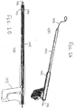
- FIGS. 1A and 1B show one such variation of suture management device (100).
- FIG. 1A shows a perspective view of suture management device (100), including handpiece (102) and catheter body (104). Also shown there is suture (106).
- FIG. 1B shows a cross-sectional side view of suture management device (100), further showing cutting assembly (108) including cutter jaws (110) held within catheter body (104). While shown in FIG. 1B as having cutter jaws (110), cutting assembly (108) may have any configuration of elements, as will be described in more detail below.
- the device may further comprise a suture engagement portion.
- FIG. 2 shows one such variation of suture management device (200).
- Suture engagement portion (206) generally engages at least a section of a suture (not shown) and may take on any suitable configuration.
- the device may further comprise a retractable guide, which will be described in more detail below.
- the suture management device comprises one or more catheter sections.
- a catheter section may be any structure capable of being advanced to a location remote from a user.
- the catheter section may comprise a tube, sheath, or catheter body, which defines one or more lumens or channels.
- the catheter section may be made of any suitable material, may have any suitable geometry or configuration, and be made to have any suitable property. All or a portion of the catheter section may be flexible. Conversely, all or a portion of the catheter section may be rigid. Of course, the catheter section may be flexible along a portion of its length, and rigid along a portion of its length.
- the catheter section may be guidable or steerable to a location remote from a user (e.g., using one or more pull or push wires, cables, or the like). Similarly, the catheter section may comprise or otherwise include one or more preshaped curves or bends along its length for facilitating positioning.
- the catheter section may also comprise one or more layers, coatings, or specialized surfaces. In some of these variations, at least a portion of the outer surface of the catheter section may be coated with, made from, or otherwise comprise a lubricious material such as PTFE. In others of these variations, the catheter section may comprise one or more coatings, reservoirs, or the like, which are configured to release one or more beneficial agents, such as, but not limited to antibiotics, antimicrobial agents, and antiinflammatory agents.
- the cutting assemblies described here may be used to sever a suture upon actuation of the suture management device.
- the cutting assembly may be contained entirely within a catheter section or a suture engagement portion, but need not be.
- the cutting assembly may be configured to come into contact only with suture. This, in turn, may prevent the cutting assembly from cutting or damaging bodily tissues.
- the forces associated with operating the cutting assembly may be internalized within the suture management device, which may in turn prevent the cutting assembly from imparting a force to the suture management device. This may further prevent tissue trauma.
- FIG. 3 illustrates a cross-sectional view of the distal end of one such variation of suture management device (300). Shown there is cutting assembly (302) enclosed within catheter section (304). In this variation, cutting assembly (302) comprises suture channel (306), actuation cannula (308) attached to actuation jaws (310), and cutter jaws (312) attached to catheter section (304) via connection sleeve (314). Also shown there is suture (316). While shown in FIG. 3 as being disposed within catheter section (304), it should be appreciated that cutting assembly (302) may be located anywhere in or on suture management device (300), including, but not limited to, a handpiece (not shown) or a suture engagement portion (not shown).
- actuation cannula (308) and actuation jaws (310) may be slidably disposed within catheter section (304), and may be engagable with a handpiece (not shown) such that activation of the handpiece may withdraw actuation cannula (308) and actuation jaws (310) proximally relative to the rest of suture management device (300).
- actuation jaws (310) As actuation jaws (310) are withdrawn proximally, they may engage cutter jaws (312). This engagement may cause cutter jaws (312), which may not slide relative to catheter section (304), to move toward the center of catheter section (304). As the cutter jaws (312) move toward each other, they may sever suture (316). The point at which cutter jaws (312) sever suture (316) may control the length of suture that remains beyond a surgical knot, for example, and it should be appreciated that the configuration of suture management device (300) may be altered to achieve a desirable cutting length.
- cutter jaws (312) may be engagable with a handpiece (not shown) to slide relative catheter section (304).
- the actuation cannula (308) may be fixed to catheter section (304), and may decrease in diameter from the distal end of actuation cannula (308) to the proximal end of actuation cannula (308).
- the handpiece is used to withdraw cutter jaws (312) proximally relative to suture management device (300)
- the cutter jaws (312) may engage actuation cannula (308). This may bring cutter jaws (312) together, and thereby cut suture (316).
- FIG. 4 shows a cross-sectional side view of one such variation of suture management device (400), including catheter section (402). Shown there are cutter jaws (404) attached to actuation cannula (406), suture channel (408), and actuator jaws (410) fixed to catheter section (402). Also shown there is suture (412). Again, actuation cannula (406) may be able to slide relative to catheter section (402).
- actuation cannula (406) may engage a handpiece (not shown) such that activation of the handpiece causes the actuation cannula (406) to slide distally relative to catheter section (402). As actuation cannula (406) slides distally, the cannula may engage actuator jaws (410). This engagement may cause cutter jaws (404) to move toward each other, which may in turn sever suture (412).
- the cutting assembly may have any number of cutting jaws. Indeed, the cutting assembly may have one, two, three, or four or more cutting jaws. In some variations, as will be described in more detail below, the cutting assembly includes alternative methods of cutting and does not include any cutting jaws. Indeed, while shown in FIGS. 3-4 as having cutting jaws, the cutting assemblies described here may have any suitable cutting structure. For example, the cutting assembly may include one more cantilevered cutting blade.
- FIG. 5 shows a cross-sectional side view of distal portion of one such variation of suture management device (500).
- suture engagement portion (502) including suture channel (504), cantilever cutting blade (506) having blade edge (508), and balloon (510) having balloon lumen (512).
- cantilever cutting blade (506) may move between a standby position (not shown) to a cutting position where the blade edge (508) passes at least partially through suture channel (504).
- balloon (510) may be inflated.
- the increase in volume of balloon (510) may bias cantilever cutting blade (506) away from the outer wall (514) of suture engagement portion (502), thereby moving cantilever cutting blade (506) to its cutting position, as shown in FIG. 5 .
- Balloon (510) may be inflated by passing a fluid through balloon lumen (512) into balloon (510). This fluid may be any suitable gas or liquid. In some variations, cantilever cutting blade (506) may naturally return to its standby position when the balloon is deflated.
- balloon (510) is attached to both cantilever cutting blade (506) and outer wall (514) of suture engagement portion (502), such that deflation of balloon (510) returns cantilever cutting blade (506) to its standby configuration.
- suture management device (500) may include some structure to return cantilever cutting blade (506) to its standby position when balloon (510) is deflated.
- suture management device (500) comprises one or more springs that bias cantilever cutting blade (506) away from the cutting position.
- suture management device (500) comprises one or more magnets that bias cantilever cutting blade (506) away from the cutting position.
- FIG. 6 illustrates a cross-sectional side view of one such variation of suture management device (600), including suture engagement portion (602) attached to catheter section (604). Shown there is blade housing (608) attached to longitudinally oriented blade (606) and inner shaft (610). Also shown there is suture (612) disposed at least partially within suture engagement portion (602). In variations such as these, blade housing (608) may be able to slide within suture engagement portion (602).
- inner shaft (610) and plunger (614) may be able to slide within suture engagement portion (602) and catheter section (604). Additionally, inner shaft (610) may be engagable with blade housing (608) and a handpiece (not shown), such that activation of the handpiece causes inner shaft (610) to move distally relative to the suture management device (600). This in turn may move the inner shaft (610), plunger (614), and suture (612) distally relative to the suture management device (600), and may cause blade (606) to sever suture (612). Additionally, activation of the handpiece may be used to cause blade housing (608) to move proximally relative to suture management device (600).
- suture management device (600) may move blade (606) proximally relative to suture management device (600), and may cause blade (606) to sever suture (612). While shown in FIG. 6 as configured to push inner shaft (610), plunger (614), and suture (612) distally relative to suture management device (600) to sever a suture (612), suture management device (600) may alternatively be configured to pull blade (606) proximally to sever a suture.
- FIGS. 7A and 7B show another variation of suture management device (700) having cutting assembly (702) with a longitudinally oriented blade (704). Shown there is suture engagement portion (706) defining a suture channel (708), blade housing (710) attached to blade (704) and spring (714), balloon (716) having a balloon lumen (718), and catheter section (720). Blade housing (710) may be capable of sliding within catheter section (720). When balloon (716) is deflated, blade housing (710) may sit in a standby position, as shown in a cross-sectional side view in FIG. 7A . In order to activate suture management device (700), balloon (716) may be inflated by passing a fluid, either liquid or gas, through balloon lumen (718).
- the inflated balloon (716) may push blade housing (710) distally relative to catheter section (720). This may in turn move blade (704) distally through blade channel (722) in suture engagement portion (706), as shown in FIG. 7B . As blade (704) moves through blade channel (722), it may also move through suture channel (708) and may thereby sever a suture (not shown).
- spring (714) may act to return blade housing (710) to its standby position.
- suture management device (700) may alternatively or additionally include magnets or other structures that act to return blade housing (710) to its standby position.
- FIGS. 8A and 8B show still another variation of a suture management device (800) having cutting assembly (802) with a longitudinally oriented blade (804). Shown there is suture engagement portion (806) defining a suture channel (808), return magnet (810), blade housing (812) including housing magnet (814) and attached to blade (804), catheter section (816), and actuator rod (818) having actuator magnet (820). Blade housing (812) and actuator rod (818) may be able to slide within catheter section (816). Furthermore, the magnets may be axially magnetized and oriented such that housing magnet (814) is repelled by both return magnet (810) and actuator magnet (820).
- the magnets may be configured such that the repulsive force between the housing magnet (810) and the actuator magnet (820) is stronger than the repulsive force between housing magnet (810) and return magnet (810).
- blade housing (812) When cutting assembly (802) is not being activated, blade housing (812) may be in a standby position, as shown in a cross-sectional side view in FIG. 8A .
- Actuator rod (818) may be engagable with a handpiece (not shown), such that activation of the handpiece causes actuator rod (818) to slide distally relative to catheter section (816).
- the repulsive force between actuator magnet (818) and housing magnet (814) may cause blade housing (812) to slide distally relative to catheter section (816), and may overcome the repulsive force between housing magnet (814) and return magnet (810). This may in turn cause blade (804) to move distally within blade channel (822), as shown in FIG. 8B . This movement may result in blade (804) severing a suture (not shown).
- the repulsive force between housing magnet (814) and return magnet (810) may cause blade housing (812) to return to its standby position.
- a return spring or other structure may act to return blade housing (812) to its standby position.
- FIGS. 9A-9D show another variation of suture management device (900) having cutting assembly (902).
- FIGS. 9A and 9B shows a cross-sectional side view and a cross-sectional perspective view, respectively, of suture management device (900) including inner cannula (904) and outer cannula (906). Also shown there is suture (908).
- Inner cannula (904) may be disposed within outer cannula (906), and may be capable of rotating relative to outer cannula (906). Additionally, inner cannula (904) may define an inner aperture (910), which may in turn have cutting edges (912), as shown in a perspective view in FIG. 9C . Similarly, outer cannula (904) may define an outer aperture (914), which may also have cutting edges (912), as shown in a perspective view in FIG. 9D .
- Inner cannula (904) and outer cannula (906) may be aligned such that at least a portion of inner aperture (910) aligns with at least a portion of outer aperture (914), enabling suture (908) to pass through the inner (910) and outer (914) apertures.
- inner cannula (904) is rotated relative to outer cannula (906), the cutting edges (912) of the inner (910) and outer (914) apertures are brought together, thereby decreasing the amount of overlap between inner (910) and outer (914) apertures, which may in turn sever suture (908).
- inner (910) and outer (914) apertures may have any size and shape. Indeed, inner (910) and outer (914) apertures may have a shape that approximates a circle, a half-circle, a triangle, a rectangle, an oval, a polygon, sections thereof or the like. Additionally, while shown in FIGS. 9A-9D as having the same size and shape, inner (910) and outer (914) apertures need not have the same size and shape. Indeed, inner (910) and outer (914) apertures may have the same shape but different sizes, may have different shapes but the same size, or may have different shapes and different sizes.
- each cutting assembly may include any feature or combination of features as described above.
- the cutting assemblies may include any number of cutting jaws, blades, apertures with cutting edges, combinations thereof and the like, and may be activated using magnets, balloons, actuator cannulas, rotating cannulas, combinations thereof or the like.
- the handpieces described here may have any suitable configuration of elements.
- the handpiece may allow a user to guide or manipulate the suture management device within a body or enclosed space.
- the handpiece may further allow a user to guide or manipulate a suture at a location remote from the user.
- the handpiece may control the actuation of one or more cutting assemblies, which may be used to sever a suture or a suture knot.
- the handpiece may comprise one or more actuation handles.
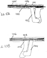
- FIG. 10A shows one such variation of handpiece (1000) comprising actuation handle (1002) and connected to catheter section (1004). Also shown there is connection sleeve (1006), actuation cannula (1008), and suture (1010). Connection sleeve (1006) may connect actuation handle (1002) to actuation cannula (1008), which may in turn cause actuation cannula (1008) to move when actuation handle (1002) is squeezed.
- Actuation handle (1002) may provide a structure that is easily graspable by a user. Additionally, actuation handle (1002) may be used to control the severing of a suture (not shown), by activating a cutting assembly (not shown).
- the actuation handle (1002) is configured to pull an actuation cannula (1006) proximally relative to catheter section (1008) when the actuation handle (1002) is compressed.
- FIG. 10B shows another variation of handpiece (1012) comprising actuation handle (1014) and connected to catheter section (1016).
- actuation handle (1014) is configured to push actuation cannula (1018) distally relative to catheter section (1016) when actuation handle (1014) is compressed.
- the actuation handle may be configured to rotate a cannula when the actuation handle is compressed.
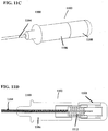
- FIGS. 11A-11D illustrate a variation of suture management device (1100) comprising handpiece (1102) connected to catheter section (1104).
- FIG. 11A shows a perspective view of suture management device (1100), comprising handle portion (1106), button (1108), and safety lock (1110).
- button (1108) may be depressed relative to handle portion (1106) to activate a cutting assembly (not shown), as shown in FIG. 11B .
- safety lock (1108) engages handpiece (1102) as shown in FIG. 11A , however, button (1108) may not be depressed.
- safety lock (1110) In order to depress button (1108), safety lock (1110) must first be removed, as shown in FIG. 11C . Once the cutting assembly has been activated, a spring (1112) disposed within handpiece (1102) may return the button to its original position, as shown in a cross-sectional side view in FIG. 11D , and the safety lock (1110) may be returned to the device.
- the handpiece may comprise any suitable structure that is capable of activating a cutting assembly. These structures include, but are not limited to triggers, sliding actuators, cranks, knobs, rotating handles, combinations thereof, and the like. Additionally, in variations where the suture management device comprises a retractable guide, as will be described in more detail below, the handpiece may additionally include one or more structures to retract retractable guide into the catheter section.
- the handle may also comprise a luer for attachment to one or more inflation lumens in the case of balloon actuating cutting mechanisms.
- the suture management devices described here may comprise one or more suture channels through which one or more sutures may be passed.
- the suture channel may have ends positioned at any two suitable locations on the suture management device. The placement of the suture channel may be determined by the configuration of a cutting assembly or another feature of the device.
- the suture passes through a suture channel that spans between the proximal and distal ends of the suture management device, as shown in FIGS. 1A and 1B .
- the suture channel enters and exits the suture management device through a suture engagement portion or other aperture.
- FIGS. 12A and 12B illustrate one variation of suture engagement portion (1200).
- FIG. 12A shows a perspective view and FIG. 12B shows a cross-sectional side view of suture engagement portion (1200).
- suture channel has a suture entrance (1212) at the distal end of suture engagement portion (1200) and a suture exit (1214) in wall (1216) of suture engagement portion (1200).
- a suture may be passed from suture entrance (1212) to suture exit (1214), or vice versa, thereby allowing suture engagement portion (1200) to engage a portion of a suture.
- FIGS. 12A and 12B show suture engagement portion (1200) as having a structure that may be independent of a catheter section (not shown), but it need not.
- the suture engagement portion may be integral with a catheter section. Additionally, the suture engagement portion may be located at any point along the device. In some variations, the suture engagement portion may be located at the distal end of the suture management device. In other variations, the suture engagement portion may be located at some point along the length of a catheter section.
- the suture engagement portion may include one or more slots on the surface of suture engagement portion. These slots may allow the suture engagement portion to engage a portion of a suture without the need to pass one end of the suture through the suture channel.
- FIGS. 13A and 13B show perspective views one such variation of suture engagement portion (1300). Shown there is suture engagement portion (1302) attached to catheter section (1304) and comprising slot (1306). Also shown there is suture (1308). Slot (1306) may comprise transverse segment (1310), longitudinal segments (1312), and suture tab (1314).
- suture (1308) may be placed within transverse segment (1310), as shown in FIG. 13A .
- the suture (1308) may then be threaded through longitudinal segments (1312) and past suture tab (1314), such that suture (1308) enters the side of suture engagement portion (1302) and exits at the distal end of suture engagement portion (1302).
- Suture tab (1314) may serve to prevent suture (1308) from disengaging with suture engagement portion (1300) while the suture management device is manipulated or advanced.
- slot (1306) may have any suitable configuration. Indeed, slot (1306) may have any combination of linear or arced sections, and these sections may be oriented within suture engagement portion (1300) in any suitable configuration. Additionally, while shown in FIGS. 13A and 13B as sized to accept one suture (1308), slot (1306) may be sized to accept two, three or four or more sutures (1308). Furthermore, suture engagement portion (1300) may have any number of slots (1306), and each slot (1306) may have any number of suture tabs (1314). Generally, suture tab (1314) may be any structure that resists movement of a suture through slot (1306).
- these suture channels may have any suitable shape or configuration.
- the suture channel may be configured such that bodily tissue is incapable of entering the suture channel. This may provide an additional level of safety as it may prevent tissue from contacting the cutting assembly.
- the suture channel may be configured to accept only one suture.
- the suture channel may be configured to accept two, three, or four or more sutures.
- the suture channel may be sized such that a suture may pass therethrough while a knotted section of the suture may not pass therethrough.
- the suture management device may be able to push a knotted section of suture to a location remote from a user.
- the suture channel may be sized to accept a retractable guide, as described in more detail below, and one or more sutures.
- the suture management device includes one or more features that allow a user to remove a suture knot in the event of an undesirable suturing outcome.
- FIGS. 14A and 14B show one such variation of suture management device (1400), including suture engagement portion (1402). More specifically, FIG. 14A shows a cross-sectional side view of suture management device (1400). Also shown there is suture channel (1406) having first section (1408) and second section (1410), cantilever blade (1412), and balloon (1414) with balloon lumen (1416). Second section (1410) of suture channel may sized such that both a suture (1418) and a suture knot (1420) may pass therethrough, as shown in FIG. 14B .
- First section (1408) may be sized such that suture (1418) may pass therethrough, but suture knot (1420) may not This may serve to position suture knot (1420) such that activation of cantilever blade (1412) will sever both suture (1418) and suture knot (1420).
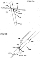
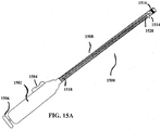
- FIGS. 15A-15C illustrate a variation of suture management device (1500).
- FIG. 15A shows a perspective view of the entire suture management device (1500). Shown there is handpiece (1502) with sliding actuator (1504) and push actuator (1506), and catheter section (1508) having suture channel (1510), retractable guide (1512) with guide loop (1514), marker (1516), and push rod (1518) with blade (1520).
- Retractable guide (1512) may be disposed within suture channel (1510), and may be withdrawn proximally into suture channel (1510) upon activation of sliding actuator (1504).
- blade (1520) may be advanced distally relative to catheter section (1508) upon activation of push actuator (1506).
- a suture (1522) may be threaded through guide loop (1514), and suture management device (1500) may be advanced over suture (1522) to a target site (1524), as shown in FIG. 15B .
- this advancement may be visualized using marker (1516) and/or imaging methods such as fluoroscopy or ultrasound to ensure suture management device (1500) is properly placed.
- retractable guide (1512) may be withdrawn into suture channel (1510) using slide actuator (1504). This may in turn cause guide loop (1514) to engage suture (1522) and pull suture (1522) at least partially within suture channel (1510), as shown in FIG. 15C .
- blade (1520) may be advanced to sever suture (1522).
- suture management device (1500) need not.
- the marker (1516) may be made of any material that is capable of being viewed by an imaging method (e.g., fluoroscopy, ultrasound, etc.).
- an imaging method e.g., fluoroscopy, ultrasound, etc.
- marker may be disposed anywhere in, on, or along suture management device (1500).
- suture management device (1500) may have any number of markers. Indeed, suture management device (1500) may have zero, one, or two or more markers.
- FIGS. 15A-15C may have any suitable structure for engaging suture (1522).
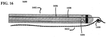
- FIG. 16 shows another variation of suture management device (1600), having catheter section (1602) with cutting assembly (1604), suture channel (1606), and retractable guide (1608) having spiral loop (1610). Also shown there is suture (1612). Spiral loop (1610) may be wound around suture (1612) to engage suture, which may allow suture management device (1600) to engage suture (1612) without the need to thread one end of suture (1612) through the retractable guide (1608). This may provide particular utility in instances where neither end of the suture is available to be threaded through retractable guide (1608).
- the retractable guide may be any structure capable of being withdrawn into a suture channel, may be made of any suitable material, and may have any suitable geometry (e.g., one or more curves or bends). Examples of suitable materials include, but are not limited to nickel titanium alloys, stainless steel, PET, polyether block amide, and combinations thereof.
- the devices described here may include any combination of elements of as described above. More specifically, the suture management devices may include any combination of handpieces, catheter sections, cutting assemblies, markers, and retractable guides as described above.
- a suture is used in a procedure at a target location.
- This procedure may be any suitable procedure, including, but not limited to, wound closure, drawing together two tissue segments, and ligating an area of tissue such as the left atrial appendage.
- a knot may then be tied at the target site.
- This knot may be any suitable knot, including but not limited to a slip knot.
- a suture management device may engage at least a portion of the suture.
- the suture management device may engage the suture in any suitable manner as described above, and this engagement may depend on the configuration of elements in the device.
- the suture management device includes a suture channel
- a free end of the suture may be threaded through one end of the suture channel and passed through the other end.
- the suture management device includes one or more slots
- the suture may be threaded through suture channel via the one or more slots.
- the suture management device comprises a retractable guide
- the retractable guide may engage the suture.
- the retractable guide comprises a guide loop
- an end of the suture may be passed through the eye of the guide loop.
- the retractable guide includes a spiral loop
- the spiral loop may be wrapped around a portion of the suture, or an end of the suture may be passed through the spiral loop.
- the suture management device may be advanced along the suture to the target site.
- the suture management device may be advanced to the target site simultaneously with engaging the suture.
- the suture acts to guide the suture management device to the target location.
- the engagement between the retractable guide and the suture may serve to lead the suture management along the length of the suture until it reaches the target site.
- the suture management device may be advanced to the target site through one or more catheters or catheter assemblies, a sheath, or other introducer, which may or may not be engaged with the suture, and which may or may not include one or more curves or bends.
- the suture management device may be advanced under fluoroscopic or ultrasonic guidance.
- a portion of the device may abut the knot.
- the suture management device may hold the knot in place, yet still allow a portion of suture to move freely through the device.
- a portion of suture may be withdrawn through the device relative to the knot. In some variations, this may serve to tighten the knot. In other variations, such as variations that include a slip knot, this may serve to cinch a loop of suture.
- the suture management device may then be activated to sever the suture.
- activation of the suture management device results in the activation of a cutting assembly.
- the retractable guide may first be withdrawn into the device, which may in turn pull a portion of the suture into the device, where it may be severed by the cutting assembly.
- suture management devices may be used to remove a knot in the case of an undesirable suturing outcome. Additionally, the suture management device may be configured to sever a suture such that a predetermined amount of suture remains.
- this may be achieved by configuring the cutting portion of the cutting assembly to sever a suture at a given distance from the distal end of the device. If the end of the suture management device is abutting the knot, a user may know how much suture will remain relative to the knot when the suture is severed. If a longer length of suture is desired, the cutting assembly may be reconfigured, or the user may withdraw the suture management device a certain amount relative to the suture (and thus the knot).
- a knot may be tied extracorporeally, and then advanced to the target site.
- a suture management device may be used to advance the knot to the target site.
- the suture management device may engage at least a portion of the suture as described above.
- a portion of the suture management device may abut or otherwise contact the knot such that as the suture management device is advanced, it pushes the knot.
- the knot may be pushed to the target location by the suture management device.
- a portion of the suture may act to guide the suture management device to the target site.
- the suture management device may also be advanced to the target site through one or more catheters or catheter assemblies, a sheath, or other introducer, which may or may not be engaged with the suture, and which may or may not include one or more curves or bends.
- the suture management device may be advanced under fluoroscopic or ultrasonic guidance. Once the knot has been positioned at the target sit, it may be tightened or removed, as described above. Similarly, once the proper tightness has been achieved, the suture management device may sever the suture, as described above.
- the suture management devices described here may be used to ligate a portion of tissue, such as the left atrial appendage.
- one end of a suture may be tied to itself using a slip knot or similar knot to create a loop.
- a suture management device may engage the suture in any of the ways as described above, and the suture management device may be used to guide the loop to a target location.
- the suture management device may be advanced to the target site through one or more catheters or catheter assemblies, sheaths, or other introducers. In some methods, this advancement may occur under fluoroscopic or ultrasonic visualization. Once at the target site, the loop may be placed around the tissue to be ligated.
- the suture management device may be manipulated to place the loop around the target tissue.
- one or more additional tools may be advanced to the target location to help place the loop around the target tissue.
- one end of the suture may be withdrawn through the suture management device to cinch the tissue.
- the knot and suture may be removed in the case of an undesirable suturing outcome, otherwise the knot may be tightened and the suture severed as described above.
Description
- In general, the devices described herein relate to the manipulation and management of sutures or suture-like materials. In particular, the devices described herein relate to remotely manipulating and managing sutures or suture-like materials.
- The use of sutures has been widespread in surgical procedures. Sutures may be used to close incisions or wounds, to join tissue segments, or ligate sections of tissue. After a suture has been put to its intended use, it is often tied into a knot to secure it in place. When the suture is placed in a region having restricted access, tying a knot may be particularly difficult Thus, knots are often formed outside of a patient and pushed toward the region. Once the knot has been positioned in the region, the ends of the suture generally need to be trimmed back, which may be difficult using standard instruments.
- In
WO 2007/056502 devices and methods used in termination of a tissue tightening procedure are described. Termination includes the cinching of a tether to tighten the tissue, locking the tether to maintain tension, and cutting excess tether. In procedures involving anchors secured to the tissue, the tether is coupled to the anchors and the tissue is tightened via tension applied to the anchors by cinching the tether. In general, the devices and methods can be used in minimally invasive surgical procedures, and can be applied through small incisions or intravascularly. A method for tightening tissue by fixedly coupling a first anchor to a tether and slidably coupling a second anchor to the tether, securing both anchors to the tissue, applying tension to the tether intravascularly, fixedly coupling the tether to the second anchor, and cutting the tether is described. The tissue to be tightened can comprise heart tissue, in particular heart valve annulus tissue. Various devices and methods for locking the tether in place and cutting excess tether are described. - In
US 2003/0236535 there is described a procedure whereby where the living tissues in a patient's body is resected as well, it is possible to suture the resected portion immediately without replacement with another treatment device after resection. Thus, prevention of bleeding from the resected portion or earlier repair of an ulcer that occurs with the resected portion can be carried out invasively and easily. - In
US 5,163,946 there is described a suture throw holder, rundown tool and cutting system for running one or more throws formed in two lengths of suture extending from a surgical site down to the surgical site so as to form a knot at the surgical site and for blindly cutting the suture ends adjacent the knot. The system comprises a support mechanism for releasably supporting a plurality of throws in a predetermined arrangement adjacent a surgical site, and a tool for removing throws from the support mechanism, running the throws down the lengths of the suture to the surgical site, and blindly cutting the suture ends at substantially equal lengths every time adjacent a knot formed by the throws at the surgical site. - Nevertheless, additional devices for remotely manipulating a suture or suture-like material may be desirable.
- According to a present invention there is provided a device for severing a portion of a suture having the features of
claim 1. - There are also described here additional devices for suture management. In some variations, the devices comprise an elongate tubular member having a proximal end, a distal end, a lumen therebetween, a cantilever blade positioned near the distal end of the elongate tubular member, and an expandable member positioned adjacent the cantilever blade for actuating the cantilever blade. The lumen is configured for the passage of a suture at least partially therethrough. The expandable member may be any suitable expandable member. In some variations, the expandable member is inflatable (e.g., a balloon). In other variations, the expandable member comprises a pair of jaws. In still other variations, the device may include one or more retractable guides that may help to bring the suture into a position where it may be severed by the cantilever blade. In some variations, the retractable guide may comprise a guide loop. In other variations, the retractable guide may comprise a spiral loop.
- Other devices for severing a suture are also described. For example, devices are also described comprising an elongate tubular member having a proximal end, a distal end, and a lumen therebetween, opposed cutting blades near the distal end, and an actuator for actuating the opposed cutting blades, where the actuator is disposed at least in part about the outer surface of the cutting blades. The actuator may be any suitable structure. In some variations, the actuator comprises an expandable member. In some of these variations, the actuator may be inflatable. In some of these variations, the actuator may be a balloon. In other variations, the actuator comprises actuation jaws configured to actuate the opposed blades when pulled proximally or pushed distally. In still other variations, the device may comprise a retractable guide as described above.
- Additional devices are also described. For example, devices are described comprising an elongate tubular member having a proximal end, a distal end, and a lumen at least partially therebetween, the elongate tubular member comprising an aperture in a wall thereof for passage of a suture therethrough, and a blade connected to a blade housing and disposed within the lumen, where the blade is oriented parallel to the longitudinal axis of the lumen, and the blade and blade housing are slidable within the lumen. In some of these variations, the device further comprises an actuator configured to actuate the slidable blade. In some of these variations, the actuator may be an expandable member. In other variations, the actuator may be a pull wire. In still other variations, the actuator may include one or more magnets. In other variations, the actuator may include a plunger. Some variations of the devices described here further comprise a handle. In some of these variations, the handle comprises one or more safety features. The devices may include one or more retractable guides as described above.
- Other described devices comprise a first elongate tubular member comprising a proximal end, a distal end, and a lumen at least partially therebetween, the first elongate tubular member having a substantially closed distal end having an aperture therein, the aperture having at least one cutting edge, and a second elongate tubular member comprising a proximal end, a distal end, and a lumen at least partially therebetween, the second elongate tubular member having a substantially closed distal end having an aperture therein, the aperture having at least one cutting edge. The first and second elongate tubular members are rotatable relative to one another such that upon rotation, the cutting edge of the first elongate tubular member and the cutting edge of the second elongate tubular member are brought toward one another. In some variations, the device comprises one or more retractable guides as described above.
- Also described here are methods for severing a suture. In some variations, the methods comprise advancing a cutting assembly over a suture, the cutting assembly comprising a first elongate tubular member comprising a proximal end, a distal end, and a lumen at least partially therebetween, the first elongate tubular member having a substantially closed distal end having an aperture therein, the aperture having at least one cutting edge and a second elongate tubular member comprising a proximal end, a distal end, and a lumen at least partially therebetween, the second elongate tubular member having a substantially closed distal end, having an aperture therein, the aperture having at least one cutting edge, the suture passing through the distal end of the cutting assembly when the apertures of the first and second elongate tubular members are aligned, and rotating the first elongate tubular member with respect to the second elongate tubular member. Rotation of the first elongate tubular member with respect to the second elongate tubular member causes the cutting edges of the first and second elongate tubular members to be brought toward one another.
- In other variations, the methods comprise retracting a blade assembly within an elongate tubular member to contact and sever a suture, the elongate tubular member comprising a proximal end, a distal end, and a lumen at least partially therethrough, the blade assembly comprising a blade and a blade housing, the blade assembly being slidably disposed within the lumen of the elongate tubular member, and wherein the blade is oriented parallel to the longitudinal axis of the lumen. In some of these variations, retracting the blade assembly comprises retracting the blade assembly using one or more magnets. In other variations, retracting the blade assembly comprises retracting the blade assembly using a shaft slidably disposed within the tubular member.
-
-
FIG. 1A is a perspective view of one variation of a suture management device.FIG. 1B is a cross-sectional side view of the same suture management device. -
FIG. 2 is a perspective view of a variation of a suture management device. -
FIG. 3 is a cross-sectional side view of a suture management device having a cutting assembly with cutting jaws. -
FIG. 4 is a cross-sectional side view of a suture management device having a cutting assembly with cutting jaws. -
FIG. 5 is a cross-sectional side view of a suture management device having a cutting assembly with a cantilevered blade. -
FIG. 6 is a cross-sectional side view of a suture management device according to the invention having a cutting assembly with a longitudinally oriented blade. -
FIGS. 7A and 7B are cross-sectional side views of a suture management device having a balloon-actuated cutting assembly. -
FIGS. 8A and 8B are cross-sectional side views of a suture management device having a magnetically actuated cutting assembly. -
FIGS. 9A is a cross-sectional side view of a suture management device having a cutting assembly with cutting apertures.FIGS. 9B-9D are perspective views of the suture management device ofFIG. 9A . -
FIGS. 10A and 10B are side views of variations of handpieces having actuator handles. -
FIGS. 11A-11C are perspective views of a variation of a handpiece having a button and a safety lock.FIG. 11D is a cross-sectional side view of the handpiece ofFIGS. 11A-11C . -
FIG. 12A is a perspective view andFIG. 12B is a cross-sectional side view of a variation of a suture engagement portion. -
FIGS. 13A and 13B are perspective views of a suture engagement portion having a slot. -
FIGS. 14A and 14B are cross-sectional side views of a suture management device that may sever a suture knot. -
FIGS. 15A-15C are cross-sectional side views of a suture management device having a retractable guide with a guide loop. -
FIG. 16 is a cross-sectional side view of a suture management device having a rectrable guide with a spiral loop. - Described here are devices for managing and manipulating sutures remotely from a user. When reference is made to the term "suture" herein, it should be understood that the term suture is generic and is intended to capture a wide variety of sutures and suture-like materials, including materials such as filaments, yarns, threads, chords, strips, and any combination of the foregoing, and the like. In some variations, the devices described here may be used to push or guide a suture, with or without a surgical knot, to a remote location. In some of these variations, the devices may be used to sever a suture at a location remote from the user. In some of these variations, the devices may be used to sever a suture at a predetermined or measured distance from a knot. Additionally, in some variations, the devices may be additionally configured to remove a knot or a knotted section of a tied suture. This may provide particular utility in instances where removing an undesirable suturing outcome is desirable.
- Generally, the devices described here comprise a handpiece, a catheter body, and one or more cutting assemblies.
FIGS. 1A and 1B show one such variation of suture management device (100).FIG. 1A shows a perspective view of suture management device (100), including handpiece (102) and catheter body (104). Also shown there is suture (106).FIG. 1B shows a cross-sectional side view of suture management device (100), further showing cutting assembly (108) including cutter jaws (110) held within catheter body (104). While shown inFIG. 1B as having cutter jaws (110), cutting assembly (108) may have any configuration of elements, as will be described in more detail below. In some variations, the device may further comprise a suture engagement portion.FIG. 2 shows one such variation of suture management device (200). Shown there is handpiece (202), catheter section (204), and suture engagement portion (206). Suture engagement portion (206), which will be described in more detail below, generally engages at least a section of a suture (not shown) and may take on any suitable configuration. In other variations, the device may further comprise a retractable guide, which will be described in more detail below. - In some variations, the suture management device comprises one or more catheter sections. A catheter section may be any structure capable of being advanced to a location remote from a user. For example, the catheter section may comprise a tube, sheath, or catheter body, which defines one or more lumens or channels. The catheter section may be made of any suitable material, may have any suitable geometry or configuration, and be made to have any suitable property. All or a portion of the catheter section may be flexible. Conversely, all or a portion of the catheter section may be rigid. Of course, the catheter section may be flexible along a portion of its length, and rigid along a portion of its length.
- The catheter section may be guidable or steerable to a location remote from a user (e.g., using one or more pull or push wires, cables, or the like). Similarly, the catheter section may comprise or otherwise include one or more preshaped curves or bends along its length for facilitating positioning. The catheter section may also comprise one or more layers, coatings, or specialized surfaces. In some of these variations, at least a portion of the outer surface of the catheter section may be coated with, made from, or otherwise comprise a lubricious material such as PTFE. In others of these variations, the catheter section may comprise one or more coatings, reservoirs, or the like, which are configured to release one or more beneficial agents, such as, but not limited to antibiotics, antimicrobial agents, and antiinflammatory agents.
- The cutting assemblies described here may be used to sever a suture upon actuation of the suture management device. The cutting assembly may be contained entirely within a catheter section or a suture engagement portion, but need not be. In variations where the cutting assembly is entirely contained within the suture management device, the cutting assembly may be configured to come into contact only with suture. This, in turn, may prevent the cutting assembly from cutting or damaging bodily tissues. Additionally, the forces associated with operating the cutting assembly may be internalized within the suture management device, which may in turn prevent the cutting assembly from imparting a force to the suture management device. This may further prevent tissue trauma.
- In some variations, the cutting assembly includes one or more cutter jaws. Indeed,
FIG. 3 illustrates a cross-sectional view of the distal end of one such variation of suture management device (300). Shown there is cutting assembly (302) enclosed within catheter section (304). In this variation, cutting assembly (302) comprises suture channel (306), actuation cannula (308) attached to actuation jaws (310), and cutter jaws (312) attached to catheter section (304) via connection sleeve (314). Also shown there is suture (316). While shown inFIG. 3 as being disposed within catheter section (304), it should be appreciated that cutting assembly (302) may be located anywhere in or on suture management device (300), including, but not limited to, a handpiece (not shown) or a suture engagement portion (not shown). In the variation shown inFIG. 3 , actuation cannula (308) and actuation jaws (310) may be slidably disposed within catheter section (304), and may be engagable with a handpiece (not shown) such that activation of the handpiece may withdraw actuation cannula (308) and actuation jaws (310) proximally relative to the rest of suture management device (300). As actuation jaws (310) are withdrawn proximally, they may engage cutter jaws (312). This engagement may cause cutter jaws (312), which may not slide relative to catheter section (304), to move toward the center of catheter section (304). As the cutter jaws (312) move toward each other, they may sever suture (316). The point at which cutter jaws (312) sever suture (316) may control the length of suture that remains beyond a surgical knot, for example, and it should be appreciated that the configuration of suture management device (300) may be altered to achieve a desirable cutting length. - While shown in
FIG. 3 as being fixed relative to catheter section (304), cutter jaws (312) may be engagable with a handpiece (not shown) to slide relative catheter section (304). In these variations, the actuation cannula (308) may be fixed to catheter section (304), and may decrease in diameter from the distal end of actuation cannula (308) to the proximal end of actuation cannula (308). When the handpiece is used to withdraw cutter jaws (312) proximally relative to suture management device (300), the cutter jaws (312) may engage actuation cannula (308). This may bring cutter jaws (312) together, and thereby cut suture (316). - While the variation of suture management device (300) shown in
FIG. 3 utilizes an actuator cannula that is withdrawn proximally relative to the catheter section, the actuator cannula may alternatively be configured to be pushed distally relative to the catheter section. Indeed,FIG. 4 shows a cross-sectional side view of one such variation of suture management device (400), including catheter section (402). Shown there are cutter jaws (404) attached to actuation cannula (406), suture channel (408), and actuator jaws (410) fixed to catheter section (402). Also shown there is suture (412). Again, actuation cannula (406) may be able to slide relative to catheter section (402). In some variations, actuation cannula (406) may engage a handpiece (not shown) such that activation of the handpiece causes the actuation cannula (406) to slide distally relative to catheter section (402). As actuation cannula (406) slides distally, the cannula may engage actuator jaws (410). This engagement may cause cutter jaws (404) to move toward each other, which may in turn sever suture (412). - While shown in
FIGS. 3-4 as having two cutting jaws, the cutting assembly may have any number of cutting jaws. Indeed, the cutting assembly may have one, two, three, or four or more cutting jaws. In some variations, as will be described in more detail below, the cutting assembly includes alternative methods of cutting and does not include any cutting jaws. Indeed, while shown inFIGS. 3-4 as having cutting jaws, the cutting assemblies described here may have any suitable cutting structure. For example, the cutting assembly may include one more cantilevered cutting blade.FIG. 5 shows a cross-sectional side view of distal portion of one such variation of suture management device (500). Shown there is suture engagement portion (502) including suture channel (504), cantilever cutting blade (506) having blade edge (508), and balloon (510) having balloon lumen (512). Generally, cantilever cutting blade (506) may move between a standby position (not shown) to a cutting position where the blade edge (508) passes at least partially through suture channel (504). - To sever a suture (not shown) disposed within suture channel (504), balloon (510) may be inflated. The increase in volume of balloon (510) may bias cantilever cutting blade (506) away from the outer wall (514) of suture engagement portion (502), thereby moving cantilever cutting blade (506) to its cutting position, as shown in
FIG. 5 . Balloon (510) may be inflated by passing a fluid through balloon lumen (512) into balloon (510). This fluid may be any suitable gas or liquid. In some variations, cantilever cutting blade (506) may naturally return to its standby position when the balloon is deflated. In other variations, balloon (510) is attached to both cantilever cutting blade (506) and outer wall (514) of suture engagement portion (502), such that deflation of balloon (510) returns cantilever cutting blade (506) to its standby configuration. In still other variations, suture management device (500) may include some structure to return cantilever cutting blade (506) to its standby position when balloon (510) is deflated. In some of these variations, suture management device (500) comprises one or more springs that bias cantilever cutting blade (506) away from the cutting position. In others of these variations, suture management device (500) comprises one or more magnets that bias cantilever cutting blade (506) away from the cutting position. - While shown in
FIGS. 3-5 as having cutting blades or jaws with cutting surfaces that are oriented approximately perpendicular to the longitudinal axis of the suture management device, the cutting assemblies may have cutting blades or jaws that are oriented at any angle relative to the suture management device.FIG. 6 illustrates a cross-sectional side view of one such variation of suture management device (600), including suture engagement portion (602) attached to catheter section (604). Shown there is blade housing (608) attached to longitudinally oriented blade (606) and inner shaft (610). Also shown there is suture (612) disposed at least partially within suture engagement portion (602). In variations such as these, blade housing (608) may be able to slide within suture engagement portion (602). Similarly, inner shaft (610) and plunger (614) may be able to slide within suture engagement portion (602) and catheter section (604). Additionally, inner shaft (610) may be engagable with blade housing (608) and a handpiece (not shown), such that activation of the handpiece causes inner shaft (610) to move distally relative to the suture management device (600). This in turn may move the inner shaft (610), plunger (614), and suture (612) distally relative to the suture management device (600), and may cause blade (606) to sever suture (612). Additionally, activation of the handpiece may be used to cause blade housing (608) to move proximally relative to suture management device (600). This in turn may move blade (606) proximally relative to suture management device (600), and may cause blade (606) to sever suture (612). While shown inFIG. 6 as configured to push inner shaft (610), plunger (614), and suture (612) distally relative to suture management device (600) to sever a suture (612), suture management device (600) may alternatively be configured to pull blade (606) proximally to sever a suture. -
FIGS. 7A and 7B show another variation of suture management device (700) having cutting assembly (702) with a longitudinally oriented blade (704). Shown there is suture engagement portion (706) defining a suture channel (708), blade housing (710) attached to blade (704) and spring (714), balloon (716) having a balloon lumen (718), and catheter section (720). Blade housing (710) may be capable of sliding within catheter section (720). When balloon (716) is deflated, blade housing (710) may sit in a standby position, as shown in a cross-sectional side view inFIG. 7A . In order to activate suture management device (700), balloon (716) may be inflated by passing a fluid, either liquid or gas, through balloon lumen (718). The inflated balloon (716) may push blade housing (710) distally relative to catheter section (720). This may in turn move blade (704) distally through blade channel (722) in suture engagement portion (706), as shown inFIG. 7B . As blade (704) moves through blade channel (722), it may also move through suture channel (708) and may thereby sever a suture (not shown). Once balloon (716) is deflated, spring (714) may act to return blade housing (710) to its standby position. Similarly, suture management device (700) may alternatively or additionally include magnets or other structures that act to return blade housing (710) to its standby position. -
FIGS. 8A and 8B show still another variation of a suture management device (800) having cutting assembly (802) with a longitudinally oriented blade (804). Shown there is suture engagement portion (806) defining a suture channel (808), return magnet (810), blade housing (812) including housing magnet (814) and attached to blade (804), catheter section (816), and actuator rod (818) having actuator magnet (820). Blade housing (812) and actuator rod (818) may be able to slide within catheter section (816). Furthermore, the magnets may be axially magnetized and oriented such that housing magnet (814) is repelled by both return magnet (810) and actuator magnet (820). Additionally, the magnets may be configured such that the repulsive force between the housing magnet (810) and the actuator magnet (820) is stronger than the repulsive force between housing magnet (810) and return magnet (810). When cutting assembly (802) is not being activated, blade housing (812) may be in a standby position, as shown in a cross-sectional side view inFIG. 8A . Actuator rod (818) may be engagable with a handpiece (not shown), such that activation of the handpiece causes actuator rod (818) to slide distally relative to catheter section (816). As actuator rod (818) moves distally, the repulsive force between actuator magnet (818) and housing magnet (814) may cause blade housing (812) to slide distally relative to catheter section (816), and may overcome the repulsive force between housing magnet (814) and return magnet (810). This may in turn cause blade (804) to move distally within blade channel (822), as shown inFIG. 8B . This movement may result in blade (804) severing a suture (not shown). When the handpiece is no longer activated, and actuator rod (818) returns to its original position, the repulsive force between housing magnet (814) and return magnet (810) may cause blade housing (812) to return to its standby position. Alternatively or additionally, a return spring or other structure may act to return blade housing (812) to its standby position. -
FIGS. 9A-9D show another variation of suture management device (900) having cutting assembly (902).FIGS. 9A and 9B shows a cross-sectional side view and a cross-sectional perspective view, respectively, of suture management device (900) including inner cannula (904) and outer cannula (906). Also shown there is suture (908). Inner cannula (904) may be disposed within outer cannula (906), and may be capable of rotating relative to outer cannula (906). Additionally, inner cannula (904) may define an inner aperture (910), which may in turn have cutting edges (912), as shown in a perspective view inFIG. 9C . Similarly, outer cannula (904) may define an outer aperture (914), which may also have cutting edges (912), as shown in a perspective view inFIG. 9D . - Inner cannula (904) and outer cannula (906) may be aligned such that at least a portion of inner aperture (910) aligns with at least a portion of outer aperture (914), enabling suture (908) to pass through the inner (910) and outer (914) apertures. When inner cannula (904) is rotated relative to outer cannula (906), the cutting edges (912) of the inner (910) and outer (914) apertures are brought together, thereby decreasing the amount of overlap between inner (910) and outer (914) apertures, which may in turn sever suture (908).
- While shown in
FIGS 9A-9D as having quarter-circle shapes, inner (910) and outer (914) apertures may have any size and shape. Indeed, inner (910) and outer (914) apertures may have a shape that approximates a circle, a half-circle, a triangle, a rectangle, an oval, a polygon, sections thereof or the like. Additionally, while shown inFIGS. 9A-9D as having the same size and shape, inner (910) and outer (914) apertures need not have the same size and shape. Indeed, inner (910) and outer (914) apertures may have the same shape but different sizes, may have different shapes but the same size, or may have different shapes and different sizes. - It should be appreciated that each cutting assembly may include any feature or combination of features as described above. Indeed, the cutting assemblies may include any number of cutting jaws, blades, apertures with cutting edges, combinations thereof and the like, and may be activated using magnets, balloons, actuator cannulas, rotating cannulas, combinations thereof or the like.
- The handpieces described here may have any suitable configuration of elements. Generally, the handpiece may allow a user to guide or manipulate the suture management device within a body or enclosed space. The handpiece may further allow a user to guide or manipulate a suture at a location remote from the user. Additionally, the handpiece may control the actuation of one or more cutting assemblies, which may be used to sever a suture or a suture knot.
- In some variations, the handpiece may comprise one or more actuation handles.
FIG. 10A shows one such variation of handpiece (1000) comprising actuation handle (1002) and connected to catheter section (1004). Also shown there is connection sleeve (1006), actuation cannula (1008), and suture (1010). Connection sleeve (1006) may connect actuation handle (1002) to actuation cannula (1008), which may in turn cause actuation cannula (1008) to move when actuation handle (1002) is squeezed. Actuation handle (1002) may provide a structure that is easily graspable by a user. Additionally, actuation handle (1002) may be used to control the severing of a suture (not shown), by activating a cutting assembly (not shown). - In some variations, such as that shown in
FIG. 10A , the actuation handle (1002) is configured to pull an actuation cannula (1006) proximally relative to catheter section (1008) when the actuation handle (1002) is compressed.FIG. 10B shows another variation of handpiece (1012) comprising actuation handle (1014) and connected to catheter section (1016). In these variations, actuation handle (1014) is configured to push actuation cannula (1018) distally relative to catheter section (1016) when actuation handle (1014) is compressed. In still other variations, the actuation handle may be configured to rotate a cannula when the actuation handle is compressed. - Additionally, in some variations the handpiece may comprise one or more safety features or locks that may prevent a user from accidentally activating a cutting assembly.
FIGS. 11A-11D illustrate a variation of suture management device (1100) comprising handpiece (1102) connected to catheter section (1104).FIG. 11A shows a perspective view of suture management device (1100), comprising handle portion (1106), button (1108), and safety lock (1110). In these variations, button (1108) may be depressed relative to handle portion (1106) to activate a cutting assembly (not shown), as shown inFIG. 11B . When safety lock (1108) engages handpiece (1102) as shown inFIG. 11A , however, button (1108) may not be depressed. In order to depress button (1108), safety lock (1110) must first be removed, as shown inFIG. 11C . Once the cutting assembly has been activated, a spring (1112) disposed within handpiece (1102) may return the button to its original position, as shown in a cross-sectional side view inFIG. 11D , and the safety lock (1110) may be returned to the device. - While shown in
FIGS. 10-11B as having actuation handles or buttons, the handpiece may comprise any suitable structure that is capable of activating a cutting assembly. These structures include, but are not limited to triggers, sliding actuators, cranks, knobs, rotating handles, combinations thereof, and the like. Additionally, in variations where the suture management device comprises a retractable guide, as will be described in more detail below, the handpiece may additionally include one or more structures to retract retractable guide into the catheter section. The handle may also comprise a luer for attachment to one or more inflation lumens in the case of balloon actuating cutting mechanisms. - Generally, the suture management devices described here may comprise one or more suture channels through which one or more sutures may be passed. The suture channel may have ends positioned at any two suitable locations on the suture management device. The placement of the suture channel may be determined by the configuration of a cutting assembly or another feature of the device. In some variations, the suture passes through a suture channel that spans between the proximal and distal ends of the suture management device, as shown in
FIGS. 1A and 1B . In other variations, the suture channel enters and exits the suture management device through a suture engagement portion or other aperture. -
FIGS. 12A and 12B illustrate one variation of suture engagement portion (1200).FIG. 12A shows a perspective view andFIG. 12B shows a cross-sectional side view of suture engagement portion (1200). Shown there is suture channel (1202), cantilever cutting blade (1204) having blade edge (1206), and balloon (1208) having balloon lumen (1210). In this variation, suture channel has a suture entrance (1212) at the distal end of suture engagement portion (1200) and a suture exit (1214) in wall (1216) of suture engagement portion (1200). A suture (not shown) may be passed from suture entrance (1212) to suture exit (1214), or vice versa, thereby allowing suture engagement portion (1200) to engage a portion of a suture. -
FIGS. 12A and 12B show suture engagement portion (1200) as having a structure that may be independent of a catheter section (not shown), but it need not. In some variations, the suture engagement portion may be integral with a catheter section. Additionally, the suture engagement portion may be located at any point along the device. In some variations, the suture engagement portion may be located at the distal end of the suture management device. In other variations, the suture engagement portion may be located at some point along the length of a catheter section. - In some variations that include a suture engagement portion, the suture engagement portion may include one or more slots on the surface of suture engagement portion. These slots may allow the suture engagement portion to engage a portion of a suture without the need to pass one end of the suture through the suture channel. These variations may find particular utility in instances when no end of a suture is available, or a tangled section of suture would otherwise prevent engagement between the suture management device and a portion of the suture.
FIGS. 13A and 13B show perspective views one such variation of suture engagement portion (1300). Shown there is suture engagement portion (1302) attached to catheter section (1304) and comprising slot (1306). Also shown there is suture (1308). Slot (1306) may comprise transverse segment (1310), longitudinal segments (1312), and suture tab (1314). - In order to engage suture engagement portion (1300), suture (1308) may be placed within transverse segment (1310), as shown in
FIG. 13A . The suture (1308) may then be threaded through longitudinal segments (1312) and past suture tab (1314), such that suture (1308) enters the side of suture engagement portion (1302) and exits at the distal end of suture engagement portion (1302). Suture tab (1314) may serve to prevent suture (1308) from disengaging with suture engagement portion (1300) while the suture management device is manipulated or advanced. - While shown in
FIGS. 13A and 13B as having both transverse (1310) and longitudinal (1312) segments, slot (1306) may have any suitable configuration. Indeed, slot (1306) may have any combination of linear or arced sections, and these sections may be oriented within suture engagement portion (1300) in any suitable configuration. Additionally, while shown inFIGS. 13A and 13B as sized to accept one suture (1308), slot (1306) may be sized to accept two, three or four or more sutures (1308). Furthermore, suture engagement portion (1300) may have any number of slots (1306), and each slot (1306) may have any number of suture tabs (1314). Generally, suture tab (1314) may be any structure that resists movement of a suture through slot (1306).
variations in which the suture management device comprises one or more suture channels, these suture channels may have any suitable shape or configuration. In some variations, the suture channel may be configured such that bodily tissue is incapable of entering the suture channel. This may provide an additional level of safety as it may prevent tissue from contacting the cutting assembly. In some variations, the suture channel may be configured to accept only one suture. In other variations, the suture channel may be configured to accept two, three, or four or more sutures. In still other variations, the suture channel may be sized such that a suture may pass therethrough while a knotted section of the suture may not pass therethrough. In these variations, the suture management device may be able to push a knotted section of suture to a location remote from a user. In yet other variations, the suture channel may be sized to accept a retractable guide, as described in more detail below, and one or more sutures. - In some variations, the suture management device includes one or more features that allow a user to remove a suture knot in the event of an undesirable suturing outcome.
FIGS. 14A and 14B show one such variation of suture management device (1400), including suture engagement portion (1402). More specifically,FIG. 14A shows a cross-sectional side view of suture management device (1400). Also shown there is suture channel (1406) having first section (1408) and second section (1410), cantilever blade (1412), and balloon (1414) with balloon lumen (1416). Second section (1410) of suture channel may sized such that both a suture (1418) and a suture knot (1420) may pass therethrough, as shown inFIG. 14B . First section (1408) may be sized such that suture (1418) may pass therethrough, but suture knot (1420) may not This may serve to position suture knot (1420) such that activation of cantilever blade (1412) will sever both suture (1418) and suture knot (1420). - In some variations, the devices described here comprise a retractable guide.
FIGS. 15A-15C illustrate a variation of suture management device (1500).FIG. 15A shows a perspective view of the entire suture management device (1500). Shown there is handpiece (1502) with sliding actuator (1504) and push actuator (1506), and catheter section (1508) having suture channel (1510), retractable guide (1512) with guide loop (1514), marker (1516), and push rod (1518) with blade (1520). Retractable guide (1512) may be disposed within suture channel (1510), and may be withdrawn proximally into suture channel (1510) upon activation of sliding actuator (1504). Similarly, blade (1520) may be advanced distally relative to catheter section (1508) upon activation of push actuator (1506). - To use suture management device (1500), a suture (1522) may be threaded through guide loop (1514), and suture management device (1500) may be advanced over suture (1522) to a target site (1524), as shown in
FIG. 15B . In some variations, this advancement may be visualized using marker (1516) and/or imaging methods such as fluoroscopy or ultrasound to ensure suture management device (1500) is properly placed. Once suture management device (1500) has been properly placed, retractable guide (1512) may be withdrawn into suture channel (1510) using slide actuator (1504). This may in turn cause guide loop (1514) to engage suture (1522) and pull suture (1522) at least partially within suture channel (1510), as shown inFIG. 15C . Once suture (1522) has been pulled into suture channel (1510), blade (1520) may be advanced to sever suture (1522). - While shown in
FIGS. 15A-15C as having a marker (1516), suture management device (1500) need not. In variations that do include a marker (1516), the marker (1516) may be made of any material that is capable of being viewed by an imaging method (e.g., fluoroscopy, ultrasound, etc.). Although shown inFIGS. 15A-15C as being located on the distal end of catheter section (1508), marker may be disposed anywhere in, on, or along suture management device (1500). Additionally, while shown inFIGS. 15A-15C as having only one marker, suture management device (1500) may have any number of markers. Indeed, suture management device (1500) may have zero, one, or two or more markers. - Additionally, while shown in
FIGS. 15A-15C as having a guide loop (1514), the retractable guide (1512) may have any suitable structure for engaging suture (1522). Indeed,FIG. 16 shows another variation of suture management device (1600), having catheter section (1602) with cutting assembly (1604), suture channel (1606), and retractable guide (1608) having spiral loop (1610). Also shown there is suture (1612). Spiral loop (1610) may be wound around suture (1612) to engage suture, which may allow suture management device (1600) to engage suture (1612) without the need to thread one end of suture (1612) through the retractable guide (1608). This may provide particular utility in instances where neither end of the suture is available to be threaded through retractable guide (1608). Generally, the retractable guide may be any structure capable of being withdrawn into a suture channel, may be made of any suitable material, and may have any suitable geometry (e.g., one or more curves or bends). Examples of suitable materials include, but are not limited to nickel titanium alloys, stainless steel, PET, polyether block amide, and combinations thereof. - It should be appreciated that the devices described here may include any combination of elements of as described above. More specifically, the suture management devices may include any combination of handpieces, catheter sections, cutting assemblies, markers, and retractable guides as described above.
- Any of the suture management devices described above may be used to sever a suture at a point remote from a user. In some methods, a suture is used in a procedure at a target location. This procedure may be any suitable procedure, including, but not limited to, wound closure, drawing together two tissue segments, and ligating an area of tissue such as the left atrial appendage. In some of these methods, a knot may then be tied at the target site. This knot may be any suitable knot, including but not limited to a slip knot. In some of these methods, a suture management device may engage at least a portion of the suture.
- The suture management device may engage the suture in any suitable manner as described above, and this engagement may depend on the configuration of elements in the device. In variations where the suture management device includes a suture channel, a free end of the suture may be threaded through one end of the suture channel and passed through the other end. In variations in which the suture management device includes one or more slots, the suture may be threaded through suture channel via the one or more slots. In variations where the suture management device comprises a retractable guide, the retractable guide may engage the suture. For example, when the retractable guide comprises a guide loop, an end of the suture may be passed through the eye of the guide loop. Alternatively, in variations where the retractable guide includes a spiral loop, and the spiral loop may be wrapped around a portion of the suture, or an end of the suture may be passed through the spiral loop.
- Once the suture management device has engaged the suture, the suture management device may be advanced along the suture to the target site. In some variations, the suture management device may be advanced to the target site simultaneously with engaging the suture. For example, in variations where the suture is threaded between the ends of a suture channel, the suture management device may be advanced toward the target site while the suture is being threaded. In some variations, the suture acts to guide the suture management device to the target location. Indeed, in variations that include a retractable guide, the engagement between the retractable guide and the suture may serve to lead the suture management along the length of the suture until it reaches the target site. Similarly, the suture management device may be advanced to the target site through one or more catheters or catheter assemblies, a sheath, or other introducer, which may or may not be engaged with the suture, and which may or may not include one or more curves or bends. In some of these methods, the suture management device may be advanced under fluoroscopic or ultrasonic guidance.
- As the suture management device is advanced to the target site, a portion of the device may abut the knot. In some of these variations, the suture management device may hold the knot in place, yet still allow a portion of suture to move freely through the device. In some of these variations, a portion of suture may be withdrawn through the device relative to the knot. In some variations, this may serve to tighten the knot. In other variations, such as variations that include a slip knot, this may serve to cinch a loop of suture.
- Once the desired knot tightness, and knot and suture placement has been achieved, the suture management device may then be activated to sever the suture. In some variations, activation of the suture management device results in the activation of a cutting assembly. It should be noted that any of the cutting assemblies as described above may be used to sever a suture. In variations that include a retractable guide, the retractable guide may first be withdrawn into the device, which may in turn pull a portion of the suture into the device, where it may be severed by the cutting assembly. In some variations, suture management devices may be used to remove a knot in the case of an undesirable suturing outcome. Additionally, the suture management device may be configured to sever a suture such that a predetermined amount of suture remains. In some variations, this may be achieved by configuring the cutting portion of the cutting assembly to sever a suture at a given distance from the distal end of the device. If the end of the suture management device is abutting the knot, a user may know how much suture will remain relative to the knot when the suture is severed. If a longer length of suture is desired, the cutting assembly may be reconfigured, or the user may withdraw the suture management device a certain amount relative to the suture (and thus the knot).
- In some methods, a knot may be tied extracorporeally, and then advanced to the target site. In other methods, a suture management device may be used to advance the knot to the target site. In these methods, the suture management device may engage at least a portion of the suture as described above. Generally, a portion of the suture management device may abut or otherwise contact the knot such that as the suture management device is advanced, it pushes the knot. As such, the knot may be pushed to the target location by the suture management device. In some of these variations, a portion of the suture may act to guide the suture management device to the target site. Of course, as described above, the suture management device may also be advanced to the target site through one or more catheters or catheter assemblies, a sheath, or other introducer, which may or may not be engaged with the suture, and which may or may not include one or more curves or bends. In these or other variations, the suture management device may be advanced under fluoroscopic or ultrasonic guidance. Once the knot has been positioned at the target sit, it may be tightened or removed, as described above. Similarly, once the proper tightness has been achieved, the suture management device may sever the suture, as described above.
- In still other methods, the suture management devices described here may be used to ligate a portion of tissue, such as the left atrial appendage. In these variations, one end of a suture may be tied to itself using a slip knot or similar knot to create a loop. A suture management device may engage the suture in any of the ways as described above, and the suture management device may be used to guide the loop to a target location. Again, the suture management device may be advanced to the target site through one or more catheters or catheter assemblies, sheaths, or other introducers. In some methods, this advancement may occur under fluoroscopic or ultrasonic visualization. Once at the target site, the loop may be placed around the tissue to be ligated. In some variations, the suture management device may be manipulated to place the loop around the target tissue. In other variations, one or more additional tools may be advanced to the target location to help place the loop around the target tissue. Once in place, one end of the suture may be withdrawn through the suture management device to cinch the tissue. The knot and suture may be removed in the case of an undesirable suturing outcome, otherwise the knot may be tightened and the suture severed as described above.
- While devices - have been described in some detail here by way of illustration and example, such illustration and example may be for purposes of clarity of understanding only. It will be readily apparent to those of ordinary skill in the art in light of the teachings herein that certain changes and modifications may be made thereto without departing from the scope of the appended claims.
Claims (3)
- A device for severing a portion of a suture comprising:an elongate tubular member (604) having a proximal end, a distal end, and a lumen (602) at least partially therebetween, the elongate tubular member (604) comprising an aperture in a wall thereof for passage of a suture therethrough such that, in use, the suture is disposed at least partially within the lumen (602);a blade (606) connected to a blade housing (608) and disposed within the lumen (602), wherein the blade (606) is oriented parallel to the longitudinal axis of the lumen, and the blade (606) and blade housing (608) are slidable within the lumen (602); anda handpiece;characterized in that it comprises an inner shaft (610) and plunger (614) slidable within the lumen (602) and in that the handpiece is such that activation of the handpiece causes the inner shaft (610), plunger (614) and suture to move relative to the blade (606) and blade housing (608) to cause the blade (606) to sever the suture.
- The device of claim 1, wherein the handpiece comprises a handle portion (1106), button (1108) and safety lock (1110), the button (1108) being depressable relative to the handle portion (1106) to activate a cutting assembly of the device and yet when the safety lock (1110) engages the handpiece the button (1108) may not be depressed.
- The device of claim 1, further comprising a retractable guide (1512).
Priority Applications (1)
| Application Number | Priority Date | Filing Date | Title |
|---|---|---|---|
| EP17166951.8A EP3272297B1 (en) | 2007-09-20 | 2008-09-17 | Devices for remote suture management |
Applications Claiming Priority (2)
| Application Number | Priority Date | Filing Date | Title |
|---|---|---|---|
| US97405107P | 2007-09-20 | 2007-09-20 | |
| PCT/US2008/076703 WO2009039191A2 (en) | 2007-09-20 | 2008-09-17 | Devices and methods for remote suture management |
Related Child Applications (1)
| Application Number | Title | Priority Date | Filing Date |
|---|---|---|---|
| EP17166951.8A Division EP3272297B1 (en) | 2007-09-20 | 2008-09-17 | Devices for remote suture management |
Publications (2)
| Publication Number | Publication Date |
|---|---|
| EP2214563A2 EP2214563A2 (en) | 2010-08-11 |
| EP2214563B1 true EP2214563B1 (en) | 2017-04-19 |
Family
ID=40468747
Family Applications (2)
| Application Number | Title | Priority Date | Filing Date |
|---|---|---|---|
| EP08831534.6A Active EP2214563B1 (en) | 2007-09-20 | 2008-09-17 | Devices and methods for remote suture management |
| EP17166951.8A Active EP3272297B1 (en) | 2007-09-20 | 2008-09-17 | Devices for remote suture management |
Family Applications After (1)
| Application Number | Title | Priority Date | Filing Date |
|---|---|---|---|
| EP17166951.8A Active EP3272297B1 (en) | 2007-09-20 | 2008-09-17 | Devices for remote suture management |
Country Status (8)
| Country | Link |
|---|---|
| US (1) | US8469983B2 (en) |
| EP (2) | EP2214563B1 (en) |
| JP (2) | JP2011500109A (en) |
| AU (1) | AU2008302329B2 (en) |
| CA (1) | CA2700261C (en) |
| ES (1) | ES2628732T3 (en) |
| HK (1) | HK1250211A1 (en) |
| WO (1) | WO2009039191A2 (en) |
Families Citing this family (65)
| Publication number | Priority date | Publication date | Assignee | Title |
|---|---|---|---|---|
| US6488689B1 (en) | 1999-05-20 | 2002-12-03 | Aaron V. Kaplan | Methods and apparatus for transpericardial left atrial appendage closure |
| ES2700851T3 (en) | 2003-10-09 | 2019-02-19 | Sentreheart Inc | Apparatus for tissue binding |
| US8608797B2 (en) | 2005-03-17 | 2013-12-17 | Valtech Cardio Ltd. | Mitral valve treatment techniques |
| US7918865B2 (en) | 2005-04-07 | 2011-04-05 | Sentreheart, Inc. | Apparatus and method for the ligation of tissue |
| US11259924B2 (en) | 2006-12-05 | 2022-03-01 | Valtech Cardio Ltd. | Implantation of repair devices in the heart |
| US9974653B2 (en) | 2006-12-05 | 2018-05-22 | Valtech Cardio, Ltd. | Implantation of repair devices in the heart |
| US11660190B2 (en) | 2007-03-13 | 2023-05-30 | Edwards Lifesciences Corporation | Tissue anchors, systems and methods, and devices |
| ES2732846T3 (en) | 2007-03-30 | 2019-11-26 | Sentreheart Inc | Devices and systems to close the left atrial ear |
| AU2008307757B2 (en) * | 2007-07-26 | 2013-07-04 | Alpha Scientific Corporation | Surgical suturing device, method and tools used therewith |
| US9226748B2 (en) * | 2007-07-26 | 2016-01-05 | Alpha Scientific Corporation | Surgical suturing device, method and tools used therewith |
| EP2214563B1 (en) | 2007-09-20 | 2017-04-19 | Sentreheart, Inc. | Devices and methods for remote suture management |
| US8490851B2 (en) * | 2008-01-15 | 2013-07-23 | Covidien Lp | Surgical stapling apparatus |
| US8382829B1 (en) | 2008-03-10 | 2013-02-26 | Mitralign, Inc. | Method to reduce mitral regurgitation by cinching the commissure of the mitral valve |
| US8911494B2 (en) | 2009-05-04 | 2014-12-16 | Valtech Cardio, Ltd. | Deployment techniques for annuloplasty ring |
| US10517719B2 (en) | 2008-12-22 | 2019-12-31 | Valtech Cardio, Ltd. | Implantation of repair devices in the heart |
| US8715342B2 (en) | 2009-05-07 | 2014-05-06 | Valtech Cardio, Ltd. | Annuloplasty ring with intra-ring anchoring |
| US8241351B2 (en) | 2008-12-22 | 2012-08-14 | Valtech Cardio, Ltd. | Adjustable partial annuloplasty ring and mechanism therefor |
| US8353956B2 (en) | 2009-02-17 | 2013-01-15 | Valtech Cardio, Ltd. | Actively-engageable movement-restriction mechanism for use with an annuloplasty structure |
| ES2705473T3 (en) | 2009-04-01 | 2019-03-25 | Sentreheart Inc | Tissue ligation device and controls thereof |
| WO2011014244A1 (en) * | 2009-07-28 | 2011-02-03 | St. Jude Medical Puerto Rico Llc | Vascular closure device with automatic suture cutter |
| US9180007B2 (en) | 2009-10-29 | 2015-11-10 | Valtech Cardio, Ltd. | Apparatus and method for guide-wire based advancement of an adjustable implant |
| WO2011067770A1 (en) | 2009-12-02 | 2011-06-09 | Valtech Cardio, Ltd. | Delivery tool for implantation of spool assembly coupled to a helical anchor |
| CN104997574B (en) | 2010-04-13 | 2017-06-06 | 森特里心脏股份有限公司 | For the method and apparatus to Cardiac interventional and placing device |
| CA2838539C (en) | 2011-06-08 | 2020-08-04 | Sentreheart, Inc. | Tissue ligation devices and tensioning devices therefor |
| US8858623B2 (en) | 2011-11-04 | 2014-10-14 | Valtech Cardio, Ltd. | Implant having multiple rotational assemblies |
| EP3656434B1 (en) | 2011-11-08 | 2021-10-20 | Valtech Cardio, Ltd. | Controlled steering functionality for implant-delivery tool |
| WO2014052818A1 (en) | 2012-09-29 | 2014-04-03 | Mitralign, Inc. | Plication lock delivery system and method of use thereof |
| US10376266B2 (en) | 2012-10-23 | 2019-08-13 | Valtech Cardio, Ltd. | Percutaneous tissue anchor techniques |
| WO2014064694A2 (en) | 2012-10-23 | 2014-05-01 | Valtech Cardio, Ltd. | Controlled steering functionality for implant-delivery tool |
| US9730793B2 (en) | 2012-12-06 | 2017-08-15 | Valtech Cardio, Ltd. | Techniques for guide-wire based advancement of a tool |
| EP2961351B1 (en) | 2013-02-26 | 2018-11-28 | Mitralign, Inc. | Devices for percutaneous tricuspid valve repair |
| CN105263425B (en) | 2013-03-12 | 2018-07-06 | 森特里心脏股份有限公司 | Organize apparatus for ligating and its method |
| US9636110B2 (en) | 2013-03-13 | 2017-05-02 | Alpha Scientific Corporation | Structural support incorporating multiple strands |
| US10449333B2 (en) | 2013-03-14 | 2019-10-22 | Valtech Cardio, Ltd. | Guidewire feeder |
| US9724195B2 (en) | 2013-03-15 | 2017-08-08 | Mitralign, Inc. | Translation catheters and systems |
| AU2014232723A1 (en) | 2013-03-15 | 2015-10-08 | Alpha Scientific Corporation | Surgical suturing device with transverse engagement |
| US10070857B2 (en) | 2013-08-31 | 2018-09-11 | Mitralign, Inc. | Devices and methods for locating and implanting tissue anchors at mitral valve commissure |
| US10299793B2 (en) | 2013-10-23 | 2019-05-28 | Valtech Cardio, Ltd. | Anchor magazine |
| WO2015066549A1 (en) | 2013-10-31 | 2015-05-07 | Sentreheart, Inc. | Devices and methods for left atrial appendage closure |
| EP3110478A4 (en) | 2014-02-28 | 2017-10-11 | Sentreheart, Inc. | Pericardial access devices and methods |
| WO2015178928A1 (en) * | 2014-05-23 | 2015-11-26 | Smith & Nephew, Inc. | Combination knot pusher and suture cutter with indexing blade |
| US9820734B2 (en) | 2014-06-24 | 2017-11-21 | Cook Medical Technologies Llc | Device for cutting suture from a distance |
| WO2016154498A1 (en) | 2015-03-24 | 2016-09-29 | Sentreheart, Inc. | Devices and methods for left atrial appendage closure |
| US10130369B2 (en) | 2015-03-24 | 2018-11-20 | Sentreheart, Inc. | Tissue ligation devices and methods therefor |
| WO2017117370A2 (en) | 2015-12-30 | 2017-07-06 | Mitralign, Inc. | System and method for reducing tricuspid regurgitation |
| US10751182B2 (en) | 2015-12-30 | 2020-08-25 | Edwards Lifesciences Corporation | System and method for reshaping right heart |
| AU2017223996B2 (en) | 2016-02-26 | 2022-02-10 | Atricure, Inc. | Devices and methods for left atrial appendage closure |
| US10702274B2 (en) | 2016-05-26 | 2020-07-07 | Edwards Lifesciences Corporation | Method and system for closing left atrial appendage |
| CN106073836B (en) * | 2016-06-01 | 2018-08-28 | 北京迈迪顶峰医疗科技有限公司 | A kind of knotter and the knotting system with the knotter |
| EP3515327B1 (en) | 2016-09-23 | 2024-02-14 | AtriCure, Inc. | Devices for left atrial appendage closure |
| JP2019533539A (en) | 2016-11-11 | 2019-11-21 | アベニュ メディカル インコーポレイテッド | System and method for percutaneous endovascular access and wire placement |
| US11045627B2 (en) | 2017-04-18 | 2021-06-29 | Edwards Lifesciences Corporation | Catheter system with linear actuation control mechanism |
| US10835221B2 (en) | 2017-11-02 | 2020-11-17 | Valtech Cardio, Ltd. | Implant-cinching devices and systems |
| US11135062B2 (en) | 2017-11-20 | 2021-10-05 | Valtech Cardio Ltd. | Cinching of dilated heart muscle |
| US20200383679A1 (en) * | 2017-11-27 | 2020-12-10 | T.A.G. Medical Devices - Agriculture Cooperative Ltd. | Multiple anchor delivery system and method |
| CN111655200B (en) | 2018-01-24 | 2023-07-14 | 爱德华兹生命科学创新(以色列)有限公司 | Contraction of annuloplasty structures |
| WO2019145941A1 (en) | 2018-01-26 | 2019-08-01 | Valtech Cardio, Ltd. | Techniques for facilitating heart valve tethering and chord replacement |
| US11844526B2 (en) | 2018-03-27 | 2023-12-19 | Atricure, Inc. | Devices and methods for left atrial appendage closure |
| CA3106104A1 (en) | 2018-07-12 | 2020-01-16 | Valtech Cardio, Ltd. | Annuloplasty systems and locking tools therefor |
| AU2019301655B2 (en) | 2018-07-12 | 2023-09-07 | Davol Inc. | Surgical instrument with fastener preload lock-out |
| IT201800007518A1 (en) * | 2018-07-26 | 2020-01-26 | Medacta Int Sa | CUTTING DEVICE |
| US11375994B2 (en) * | 2019-07-12 | 2022-07-05 | Abbot Cardiovascular Systems, Inc. | Methods, systems, and devices for positioning sutures for closing an opening in tissue |
| CN114786621A (en) | 2019-10-29 | 2022-07-22 | 爱德华兹生命科学创新(以色列)有限公司 | Annuloplasty and tissue anchoring techniques |
| US11890002B2 (en) | 2020-04-29 | 2024-02-06 | Medos International Sarl | Knotless anchor insertion |
| USD1019945S1 (en) | 2021-12-30 | 2024-03-26 | Medos International Sarl | Suture anchor insertion device |
Family Cites Families (249)
| Publication number | Priority date | Publication date | Assignee | Title |
|---|---|---|---|---|
| US3496932A (en) | 1967-12-22 | 1970-02-24 | Gen Motors Corp | Method and apparatus for substernal cardiac massage |
| US3802074A (en) * | 1971-05-21 | 1974-04-09 | C Hoppe | Surgical suture extractor |
| US3841685A (en) | 1973-02-01 | 1974-10-15 | A Kolodziej | Line handling device |
| US4030509A (en) | 1975-09-30 | 1977-06-21 | Mieczyslaw Mirowski | Implantable electrodes for accomplishing ventricular defibrillation and pacing and method of electrode implantation and utilization |
| US3999555A (en) | 1975-10-28 | 1976-12-28 | Medtronic, Inc. | Atrial pinch on lead and insertion tool |
| GB1506142A (en) * | 1975-11-17 | 1978-04-05 | Akiyama T | Cutting apparatus for surgical thread |
| US4069825A (en) * | 1976-01-28 | 1978-01-24 | Taichiro Akiyama | Surgical thread and cutting apparatus for the same |
| US4319562A (en) | 1977-12-28 | 1982-03-16 | The University Of Virginia Alumni Patents Foundation | Method and apparatus for permanent epicardial pacing or drainage of pericardial fluid and pericardial biopsy |
| US4181123A (en) | 1977-12-28 | 1980-01-01 | The University Of Virginia Alumni Patents Foundation | Apparatus for cardiac surgery and treatment of cardiovascular disease |
| US4249536A (en) | 1979-05-14 | 1981-02-10 | Vega Roger E | Urological catheter |
| US4257278A (en) | 1979-08-24 | 1981-03-24 | General Electric Company | Quantitative volume blood flow measurement by an ultrasound imaging system featuring a Doppler modality |
| US4765341A (en) | 1981-06-22 | 1988-08-23 | Mieczyslaw Mirowski | Cardiac electrode with attachment fin |
| GB2150889B (en) | 1983-12-08 | 1987-06-03 | Thomas Ball Mcglinn | Rescue device |
| US4662377A (en) | 1985-11-07 | 1987-05-05 | Mieczyslaw Mirowski | Cardioverting method and apparatus utilizing catheter and patch electrodes |
| US4817608A (en) | 1987-05-29 | 1989-04-04 | Mieczyslaw Mirowski | Cardioverting transvenous catheter/patch electrode system and method for its use |
| US5033477A (en) | 1987-11-13 | 1991-07-23 | Thomas J. Fogarty | Method and apparatus for providing intrapericardial access and inserting intrapericardial electrodes |
| US4901405A (en) | 1988-08-25 | 1990-02-20 | Grover Alfred H | Self-aligning magnetic necklace clasp |
| US4944753A (en) | 1988-09-26 | 1990-07-31 | Burgess Frank M | Method for producing retro-sternal space |
| US5678547A (en) | 1988-12-22 | 1997-10-21 | Biofield Corp. | Method and apparatus for screening or sensing bodily conditions using DC biopotentials |
| US4991578A (en) | 1989-04-04 | 1991-02-12 | Siemens-Pacesetter, Inc. | Method and system for implanting self-anchoring epicardial defibrillation electrodes |
| US5433730A (en) | 1989-05-03 | 1995-07-18 | Intermedics, Inc. | Conductive pouch electrode for defibrillation |
| US4991603A (en) | 1989-10-30 | 1991-02-12 | Siemens-Pacesetter, Inc. | Transvenously placed defibrillation leads via an inferior vena cava access site and method of use |
| US4998975A (en) | 1989-10-30 | 1991-03-12 | Siemens-Pacesetter, Inc. | Travenously placed defibrillation leads |
| US5226908A (en) | 1989-12-05 | 1993-07-13 | Inbae Yoon | Multi-functional instruments and stretchable ligating and occluding devices |
| US5163946A (en) * | 1990-04-25 | 1992-11-17 | Mitek Surgical Products, Inc. | Suture rundown tool and cutter system |
| US5176691A (en) | 1990-09-11 | 1993-01-05 | Pierce Instruments, Inc. | Knot pusher |
| US5108406A (en) | 1990-12-14 | 1992-04-28 | L.P. Wagi | Instrument to retrieve intraluminal objects |
| US5181123A (en) | 1991-03-29 | 1993-01-19 | Thomson Consumer Electronics, Inc. | Cathode-ray tube having a shrinkfit implosion protection band with tension limiting means |
| US5676636A (en) | 1994-07-22 | 1997-10-14 | Origin Medsystems, Inc. | Method for creating a mediastinal working space |
| US5243977A (en) | 1991-06-26 | 1993-09-14 | Trabucco Hector O | Pacemaker |
| US5452733A (en) | 1993-02-22 | 1995-09-26 | Stanford Surgical Technologies, Inc. | Methods for performing thoracoscopic coronary artery bypass |
| US5766151A (en) | 1991-07-16 | 1998-06-16 | Heartport, Inc. | Endovascular system for arresting the heart |
| US5269326A (en) | 1991-10-24 | 1993-12-14 | Georgetown University | Method for transvenously accessing the pericardial space via the right auricle for medical procedures |
| US5281238A (en) | 1991-11-22 | 1994-01-25 | Chin Albert K | Endoscopic ligation instrument |
| US5163942A (en) | 1991-12-09 | 1992-11-17 | Everest Medical Corporation | Surgical instrument with grasping loop for laparoscopic procedures |
| US5226535A (en) | 1992-02-14 | 1993-07-13 | Ethicon, Inc. | Package for endoscopic suture loop and cannula |
| US5318578A (en) | 1992-03-17 | 1994-06-07 | Harrith M. Hasson | Apparatus for delivering a suture into a body cavity and method of using the apparatus |
| US5540711A (en) | 1992-06-02 | 1996-07-30 | General Surgical Innovations, Inc. | Apparatus and method for developing an anatomic space for laparoscopic procedures with laparoscopic visualization |
| US5336252A (en) | 1992-06-22 | 1994-08-09 | Cohen Donald M | System and method for implanting cardiac electrical leads |
| US5242459A (en) | 1992-07-10 | 1993-09-07 | Laparomed Corporation | Device and method for applying a ligating loop |
| US5443481A (en) | 1992-07-27 | 1995-08-22 | Lee; Benjamin I. | Methods and device for percutaneous sealing of arterial puncture sites |
| US5676651A (en) | 1992-08-06 | 1997-10-14 | Electric Boat Corporation | Surgically implantable pump arrangement and method for pumping body fluids |
| JP2552820B2 (en) | 1992-09-23 | 1996-11-13 | ターゲット セラピューティクス,インコーポレイテッド | Medical recovery equipment |
| US5300078A (en) | 1992-10-09 | 1994-04-05 | Laparomed Corporation | Device and method for applying large-diameter ligating loop |
| ES2111689T3 (en) | 1992-11-17 | 1998-03-16 | Smith & Nephew Inc | LOCKING DEVICE FOR THE IMMOBILIZATION OF A THREAD OF SUTURE. |
| DE4240533C1 (en) | 1992-11-27 | 1994-04-07 | Ethicon Gmbh | Endoscopic loop with application instrument - has knife on distal end of actuating member acting against free portion of surgical thread |
| US6283127B1 (en) | 1992-12-03 | 2001-09-04 | Wesley D. Sterman | Devices and methods for intracardiac procedures |
| US5340129A (en) | 1993-01-21 | 1994-08-23 | Minnesota Mining And Manufacturing Company | Saw blade retention system |
| USRE36269E (en) | 1993-01-21 | 1999-08-17 | Minnesota Mining And Manufacturing Company | Saw blade retention system |
| US6494211B1 (en) | 1993-02-22 | 2002-12-17 | Hearport, Inc. | Device and methods for port-access multivessel coronary artery bypass surgery |
| US6346074B1 (en) | 1993-02-22 | 2002-02-12 | Heartport, Inc. | Devices for less invasive intracardiac interventions |
| US5797960A (en) | 1993-02-22 | 1998-08-25 | Stevens; John H. | Method and apparatus for thoracoscopic intracardiac procedures |
| US6010531A (en) | 1993-02-22 | 2000-01-04 | Heartport, Inc. | Less-invasive devices and methods for cardiac valve surgery |
| US6161543A (en) | 1993-02-22 | 2000-12-19 | Epicor, Inc. | Methods of epicardial ablation for creating a lesion around the pulmonary veins |
| US5728151A (en) | 1993-02-22 | 1998-03-17 | Heartport, Inc. | Intercostal access devices for less-invasive cardiovascular surgery |
| US5799661A (en) | 1993-02-22 | 1998-09-01 | Heartport, Inc. | Devices and methods for port-access multivessel coronary artery bypass surgery |
| AU6405994A (en) | 1993-03-11 | 1994-09-26 | Wilson Greatbatch Ltd. | Laparoscopic surgical grasper |
| US5403331A (en) | 1993-03-12 | 1995-04-04 | United States Surgical Corporation | Looped suture ligating device containing a heat-shrinkable element |
| US5306234A (en) | 1993-03-23 | 1994-04-26 | Johnson W Dudley | Method for closing an atrial appendage |
| US5437643A (en) * | 1993-05-17 | 1995-08-01 | Ethicon, Inc. | Safety interposer for surgical instruments |
| US6258021B1 (en) | 1993-06-17 | 2001-07-10 | Peter J. Wilk | Intrapericardial assist method |
| US6155968A (en) | 1998-07-23 | 2000-12-05 | Wilk; Peter J. | Method and device for improving cardiac function |
| US5423830A (en) | 1993-07-07 | 1995-06-13 | Schneebaum; Cary W. | Polyp retrieval method and associated instrument assembly |
| US5683364A (en) | 1993-07-30 | 1997-11-04 | Zadini; Filiberto | Percutaneous cardiac pump for cardiopulmonary resuscitation |
| US5449367A (en) | 1993-08-02 | 1995-09-12 | Kadry; Othman | Pre-tied knot for surgical use and method of using same |
| US5385156A (en) | 1993-08-27 | 1995-01-31 | Rose Health Care Systems | Diagnostic and treatment method for cardiac rupture and apparatus for performing the same |
| US5609597A (en) | 1993-12-09 | 1997-03-11 | Lehrer; Theodor | Apparatus and method of extracorporeally applying and locking laparoscopic suture and loop ligatures |
| US5536273A (en) | 1993-12-09 | 1996-07-16 | Lehrer; Theodor | Apparatus and method of extracorporeally applying and locking laparoscopic suture and loop ligatures |
| WO1995018593A1 (en) | 1994-01-10 | 1995-07-13 | Cardassist Incorporated | Ventricular assist device |
| US5423821A (en) | 1994-01-18 | 1995-06-13 | Pasque; Michael K. | Sternal closure device |
| WO1995032669A1 (en) | 1994-06-01 | 1995-12-07 | Perclose, Inc. | Apparatus and method for advancing surgical knots |
| US5681278A (en) | 1994-06-23 | 1997-10-28 | Cormedics Corp. | Coronary vasculature treatment method |
| US5498228A (en) | 1994-08-08 | 1996-03-12 | John W. Royalty | Electromagnetic bi-ventricular assist device |
| US5601576A (en) | 1994-08-10 | 1997-02-11 | Heartport Inc. | Surgical knot pusher and method of use |
| US7175619B2 (en) | 1994-10-07 | 2007-02-13 | Boston Scientific Scimed, Inc. | Loop structures for positioning a diagnostic or therapeutic element on the epicardium or other organ surface |
| US6152920A (en) | 1997-10-10 | 2000-11-28 | Ep Technologies, Inc. | Surgical method and apparatus for positioning a diagnostic or therapeutic element within the body |
| US6464700B1 (en) | 1994-10-07 | 2002-10-15 | Scimed Life Systems, Inc. | Loop structures for positioning a diagnostic or therapeutic element on the epicardium or other organ surface |
| US5624430A (en) | 1994-11-28 | 1997-04-29 | Eton; Darwin | Magnetic device to assist transcorporeal guidewire placement |
| US5707336A (en) | 1995-01-09 | 1998-01-13 | Cardassist Incorporated | Ventricular assist device |
| US5888247A (en) | 1995-04-10 | 1999-03-30 | Cardiothoracic Systems, Inc | Method for coronary artery bypass |
| US5797870A (en) | 1995-06-07 | 1998-08-25 | Indiana University Foundation | Pericardial delivery of therapeutic and diagnostic agents |
| US6132438A (en) | 1995-06-07 | 2000-10-17 | Ep Technologies, Inc. | Devices for installing stasis reducing means in body tissue |
| US6224584B1 (en) | 1997-01-14 | 2001-05-01 | Eclipse Surgical Technologies, Inc. | Therapeutic and diagnostic agent delivery |
| US5840059A (en) | 1995-06-07 | 1998-11-24 | Cardiogenesis Corporation | Therapeutic and diagnostic agent delivery |
| US5827216A (en) | 1995-06-07 | 1998-10-27 | Cormedics Corp. | Method and apparatus for accessing the pericardial space |
| US5902311A (en) | 1995-06-15 | 1999-05-11 | Perclose, Inc. | Low profile intraluminal suturing device and method |
| US5900433A (en) | 1995-06-23 | 1999-05-04 | Cormedics Corp. | Vascular treatment method and apparatus |
| US5814052A (en) | 1995-06-29 | 1998-09-29 | Nakao; Naomi L. | Surgical cauterization snare with ligating suture |
| US5797946A (en) | 1995-07-13 | 1998-08-25 | Origin Medsystems, Inc. | Method for arterial harvest and anastomosis for coronary bypass grafting |
| US5693059A (en) | 1995-09-15 | 1997-12-02 | Yoon; Inbae | Ligating instrument with multiple loop ligature supply and methods therefor |
| US5704943A (en) | 1995-09-25 | 1998-01-06 | Yoon; Inbae | Ligating instrument with multiple loop ligature supply and methods therefor |
| JP3293118B2 (en) | 1995-10-18 | 2002-06-17 | ニプロ株式会社 | Catheter assembly for endocardial suture surgery |
| US5716392A (en) | 1996-01-05 | 1998-02-10 | Medtronic, Inc. | Minimally invasive medical electrical lead |
| US5792151A (en) | 1996-01-24 | 1998-08-11 | The Ohio State University | Method and apparatus for ligating a blood vessel, tissue or other bodily duct |
| US5752526A (en) | 1996-02-19 | 1998-05-19 | The Cleveland Clinic Foundation | Minimally invasive cardiac surgery procedure |
| US5727569A (en) | 1996-02-20 | 1998-03-17 | Cardiothoracic Systems, Inc. | Surgical devices for imposing a negative pressure to fix the position of cardiac tissue during surgery |
| US5735877A (en) | 1996-02-28 | 1998-04-07 | Pagedas; Anthony C. | Self locking suture lock |
| US5871496A (en) | 1996-03-20 | 1999-02-16 | Cardiothoracic Systems, Inc. | Surgical instrument for facilitating the detachment of an artery and the like |
| JP4136020B2 (en) | 1996-04-17 | 2008-08-20 | オリンパス株式会社 | Medical ligature |
| US5683445A (en) | 1996-04-29 | 1997-11-04 | Swoyer; John M. | Medical electrical lead |
| US5766216A (en) | 1996-05-30 | 1998-06-16 | Gangal; Hanamraddi T. | Band applicator for appendicular and meso-appendicular stumps |
| US6059750A (en) | 1996-08-01 | 2000-05-09 | Thomas J. Fogarty | Minimally invasive direct cardiac massage device and method |
| US5766217A (en) | 1996-09-23 | 1998-06-16 | Christy; William J. | Surgical loop delivery device and method |
| US6152936A (en) | 1996-09-23 | 2000-11-28 | Esd Medical, Llc | Surgical loop delivery device |
| US6237605B1 (en) | 1996-10-22 | 2001-05-29 | Epicor, Inc. | Methods of epicardial ablation |
| US6311692B1 (en) | 1996-10-22 | 2001-11-06 | Epicor, Inc. | Apparatus and method for diagnosis and therapy of electrophysiological disease |
| US6206004B1 (en) | 1996-12-06 | 2001-03-27 | Comedicus Incorporated | Treatment method via the pericardial space |
| US5910129A (en) | 1996-12-19 | 1999-06-08 | Ep Technologies, Inc. | Catheter distal assembly with pull wires |
| US6332880B1 (en) | 1996-12-19 | 2001-12-25 | Ep Technologies, Inc. | Loop structures for supporting multiple electrode elements |
| US6048329A (en) | 1996-12-19 | 2000-04-11 | Ep Technologies, Inc. | Catheter distal assembly with pull wires |
| US5961440A (en) | 1997-01-02 | 1999-10-05 | Myocor, Inc. | Heart wall tension reduction apparatus and method |
| US5882299A (en) | 1997-01-31 | 1999-03-16 | Minnesota Scientific, Inc. | Device and procedure for minimally invasive coronary anastomosis |
| US5699748A (en) | 1997-02-06 | 1997-12-23 | Linskey, Jr.; Edward | Line handling device for positioning and handling of mooring lines |
| US6045570A (en) | 1997-02-11 | 2000-04-04 | Biointerventional Corporation | Biological sealant mixture and system for use in percutaneous occlusion of puncture sites and tracts in the human body and method |
| US5779727A (en) | 1997-02-18 | 1998-07-14 | Orejola; Wilmo C. | Hydraulically operated surgical scissors |
| US6120431A (en) | 1997-03-14 | 2000-09-19 | Allegheny-Singer Research Institute | Method for assisting stystolic and diastolic cardiac function |
| US6319201B1 (en) | 1997-10-15 | 2001-11-20 | Peter J. Wilk | Imaging device and associated method |
| US6200303B1 (en) | 1997-04-30 | 2001-03-13 | Beth Israel Deaconess Medical Center, Inc. | Method and kit for transvenously accessing the pericardial space via the right atrium |
| US5968010A (en) | 1997-04-30 | 1999-10-19 | Beth Israel Deaconess Medical Center, Inc. | Method for transvenously accessing the pericardial space via the right atrium |
| US5908429A (en) | 1997-05-01 | 1999-06-01 | Yoon; Inbae | Methods of anatomical tissue ligation |
| US5895298A (en) | 1997-05-29 | 1999-04-20 | Biofield Corp. | DC biopotential electrode connector and connector condition sensor |
| US5897586A (en) | 1997-08-15 | 1999-04-27 | Regents Of The University Of Minnesota | Implantable defibrillator lead |
| US6592552B1 (en) | 1997-09-19 | 2003-07-15 | Cecil C. Schmidt | Direct pericardial access device and method |
| US5972013A (en) | 1997-09-19 | 1999-10-26 | Comedicus Incorporated | Direct pericardial access device with deflecting mechanism and method |
| US5871531A (en) | 1997-09-25 | 1999-02-16 | Medtronic, Inc. | Medical electrical lead having tapered spiral fixation |
| US6006122A (en) | 1997-09-25 | 1999-12-21 | Medtronic, Inc. | Medical electrical lead |
| US5991668A (en) | 1997-09-25 | 1999-11-23 | Medtronic, Inc. | Medical electrical lead |
| US6071281A (en) | 1998-05-05 | 2000-06-06 | Ep Technologies, Inc. | Surgical method and apparatus for positioning a diagnostic or therapeutic element within the body and remote power control unit for use with same |
| US6610055B1 (en) | 1997-10-10 | 2003-08-26 | Scimed Life Systems, Inc. | Surgical method for positioning a diagnostic or therapeutic element on the epicardium or other organ surface |
| US6015382A (en) | 1997-10-16 | 2000-01-18 | General Surgical Innovations, Inc. | Inflatable manipulator for organ positioning during surgery and method of use |
| US5908435A (en) | 1997-10-23 | 1999-06-01 | Samuels; Shaun L. W. | Expandable lumen device and method of use |
| US6241667B1 (en) | 1998-01-15 | 2001-06-05 | Lumend, Inc. | Catheter apparatus for guided transvascular treatment of arterial occlusions |
| WO1999035977A1 (en) | 1998-01-16 | 1999-07-22 | Lumend, Inc. | Catheter apparatus for treating arterial occlusions |
| US6090042A (en) | 1998-01-23 | 2000-07-18 | Rullo; Janice Lee | Surgical support apparatus with adjustable rake and adjustable cable lifting disk |
| US6083153A (en) | 1998-01-23 | 2000-07-04 | Rultract, Inc. | Xiphoid retraction system and method of performing reoperative midsternotomy |
| US5964699A (en) | 1998-01-23 | 1999-10-12 | Rultract, Inc. | Surgical support apparatus with a Z-shape rake plate |
| US5984866A (en) | 1998-01-23 | 1999-11-16 | Rultract, Inc. | Surgical support apparatus with splined coupling, cross bar support and head-to-toe extension for surgical retractor apparatus |
| US6148230A (en) | 1998-01-30 | 2000-11-14 | Uab Research Foundation | Method for the monitoring and treatment of spontaneous cardiac arrhythmias |
| US6296630B1 (en) | 1998-04-08 | 2001-10-02 | Biocardia, Inc. | Device and method to slow or stop the heart temporarily |
| US6095968A (en) | 1998-04-10 | 2000-08-01 | Cardio Technologies, Inc. | Reinforcement device |
| US6199556B1 (en) | 1998-05-01 | 2001-03-13 | Cardiothoracic Systems, Inc. | Xyphoid access for cardiac surgical procedures |
| US6231518B1 (en) | 1998-05-26 | 2001-05-15 | Comedicus Incorporated | Intrapericardial electrophysiological procedures |
| US6149595A (en) | 1998-07-02 | 2000-11-21 | Seitz; Walter S. | Noninvasive apparatus and method for the determination of cardiac valve function |
| US7790192B2 (en) | 1998-08-14 | 2010-09-07 | Accessclosure, Inc. | Apparatus and methods for sealing a vascular puncture |
| EP1112043B1 (en) | 1998-09-10 | 2006-04-05 | Percardia, Inc. | Tmr shunt |
| US7713282B2 (en) | 1998-11-06 | 2010-05-11 | Atritech, Inc. | Detachable atrial appendage occlusion balloon |
| US7128073B1 (en) | 1998-11-06 | 2006-10-31 | Ev3 Endovascular, Inc. | Method and device for left atrial appendage occlusion |
| US6152144A (en) | 1998-11-06 | 2000-11-28 | Appriva Medical, Inc. | Method and device for left atrial appendage occlusion |
| AT3305U1 (en) | 1998-12-16 | 2000-01-25 | Ami Gmbh | ENDOSCOPIC INSTRUMENT WITH THREAD LOOP |
| US6333347B1 (en) | 1999-01-29 | 2001-12-25 | Angiotech Pharmaceuticals & Advanced Research Tech | Intrapericardial delivery of anti-microtubule agents |
| US6280415B1 (en) | 1999-03-10 | 2001-08-28 | W. Dudley Johnson | Tissue traction device |
| US6077277A (en) * | 1999-04-05 | 2000-06-20 | Starion Instruments, Inc. | Suture welding device |
| US6752813B2 (en) | 1999-04-09 | 2004-06-22 | Evalve, Inc. | Methods and devices for capturing and fixing leaflets in valve repair |
| US7666204B2 (en) | 1999-04-09 | 2010-02-23 | Evalve, Inc. | Multi-catheter steerable guiding system and methods of use |
| DE60045429D1 (en) | 1999-04-09 | 2011-02-03 | Evalve Inc | Device for heart valve surgery |
| US6045571A (en) | 1999-04-14 | 2000-04-04 | Ethicon, Inc. | Multifilament surgical cord |
| US6488689B1 (en) | 1999-05-20 | 2002-12-03 | Aaron V. Kaplan | Methods and apparatus for transpericardial left atrial appendage closure |
| US7264587B2 (en) | 1999-08-10 | 2007-09-04 | Origin Medsystems, Inc. | Endoscopic subxiphoid surgical procedures |
| US20040102804A1 (en) | 1999-08-10 | 2004-05-27 | Chin Albert K. | Apparatus and methods for endoscopic surgical procedures |
| US20030187460A1 (en) | 1999-08-10 | 2003-10-02 | Chin Albert K. | Methods and apparatus for endoscopic cardiac surgery |
| JP3901421B2 (en) | 1999-08-19 | 2007-04-04 | 有限会社 パックス オプティカ ジャパン | Organ anastomosis device |
| US6328689B1 (en) | 2000-03-23 | 2001-12-11 | Spiration, Inc., | Lung constriction apparatus and method |
| US6423051B1 (en) | 1999-09-16 | 2002-07-23 | Aaron V. Kaplan | Methods and apparatus for pericardial access |
| US6231561B1 (en) | 1999-09-20 | 2001-05-15 | Appriva Medical, Inc. | Method and apparatus for closing a body lumen |
| US6652555B1 (en) | 1999-10-27 | 2003-11-25 | Atritech, Inc. | Barrier device for covering the ostium of left atrial appendage |
| US6613062B1 (en) | 1999-10-29 | 2003-09-02 | Medtronic, Inc. | Method and apparatus for providing intra-pericardial access |
| US7758521B2 (en) | 1999-10-29 | 2010-07-20 | Medtronic, Inc. | Methods and systems for accessing the pericardial space |
| US6293906B1 (en) | 2000-01-14 | 2001-09-25 | Acorn Cardiovascular, Inc. | Delivery of cardiac constraint jacket |
| US6692491B1 (en) | 2000-03-24 | 2004-02-17 | Scimed Life Systems, Inc. | Surgical methods and apparatus for positioning a diagnostic or therapeutic element around one or more pulmonary veins or other body structures |
| US7056294B2 (en) | 2000-04-13 | 2006-06-06 | Ev3 Sunnyvale, Inc | Method and apparatus for accessing the left atrial appendage |
| WO2002015795A2 (en) | 2000-08-25 | 2002-02-28 | Sutura, Inc. | Suture cutter |
| US6830174B2 (en) | 2000-08-30 | 2004-12-14 | Cerebral Vascular Applications, Inc. | Medical instrument |
| US6666861B1 (en) | 2000-10-05 | 2003-12-23 | James R. Grabek | Atrial appendage remodeling device and method |
| US6635065B2 (en) | 2000-11-16 | 2003-10-21 | Vascular Control Systems, Inc. | Doppler directed suture ligation device and method |
| US7905900B2 (en) | 2003-01-30 | 2011-03-15 | Integrated Vascular Systems, Inc. | Clip applier and methods of use |
| US6786898B2 (en) | 2003-01-15 | 2004-09-07 | Medtronic, Inc. | Methods and tools for accessing an anatomic space |
| US20020107531A1 (en) | 2001-02-06 | 2002-08-08 | Schreck Stefan G. | Method and system for tissue repair using dual catheters |
| US6807968B2 (en) | 2001-04-26 | 2004-10-26 | Medtronic, Inc. | Method and system for treatment of atrial tachyarrhythmias |
| US7011671B2 (en) | 2001-07-18 | 2006-03-14 | Atritech, Inc. | Cardiac implant device tether system and method |
| US6755338B2 (en) | 2001-08-29 | 2004-06-29 | Cerebral Vascular Applications, Inc. | Medical instrument |
| US6605047B2 (en) * | 2001-09-10 | 2003-08-12 | Vivant Medical, Inc. | Biopsy marker delivery system |
| US6789509B1 (en) | 2001-09-24 | 2004-09-14 | Guy Dale Motsinger | Lariat with low-friction honda arm socks |
| US7004951B2 (en) * | 2001-10-04 | 2006-02-28 | Gibbens Group Llc | Cycling suturing and knot-tying device |
| US20060020336A1 (en) | 2001-10-23 | 2006-01-26 | Liddicoat John R | Automated annular plication for mitral valve repair |
| US20050149069A1 (en) | 2001-12-04 | 2005-07-07 | Bertolero Arthur A. | Left atrial appendage devices and methods |
| US7749157B2 (en) | 2001-12-04 | 2010-07-06 | Estech, Inc. (Endoscopic Technologies, Inc.) | Methods and devices for minimally invasive cardiac surgery for atrial fibrillation |
| US7918867B2 (en) * | 2001-12-07 | 2011-04-05 | Abbott Laboratories | Suture trimmer |
| US6978176B2 (en) | 2001-12-08 | 2005-12-20 | Lattouf Omar M | Treatment for patient with congestive heart failure |
| US6656175B2 (en) | 2001-12-11 | 2003-12-02 | Medtronic, Inc. | Method and system for treatment of atrial tachyarrhythmias |
| US7618425B2 (en) * | 2002-01-30 | 2009-11-17 | Olympus Corporation | Endoscopic suturing system |
| CA2473041A1 (en) * | 2002-02-22 | 2003-08-28 | Cochlear Limited | An insertion device for an electrode array |
| US8105342B2 (en) | 2002-05-08 | 2012-01-31 | Apollo Endosurgery, Inc. | Apparatus for ligating/suturing living tissues and system for resecting/suturing living tissues |
| US7008418B2 (en) | 2002-05-09 | 2006-03-07 | Stereotaxis, Inc. | Magnetically assisted pulmonary vein isolation |
| US7527634B2 (en) | 2002-05-14 | 2009-05-05 | University Of Pittsburgh | Device and method of use for functional isolation of animal or human tissues |
| US20060122633A1 (en) * | 2002-06-13 | 2006-06-08 | John To | Methods and devices for termination |
| US8287561B2 (en) | 2002-06-28 | 2012-10-16 | Boston Scientific Scimed, Inc. | Balloon-type actuator for surgical applications |
| US7041111B2 (en) | 2002-08-02 | 2006-05-09 | Boston Scientific Scimed, Inc. | Placing sutures |
| US20040116943A1 (en) | 2002-12-13 | 2004-06-17 | Brandt C. Phillip | Method and apparatus for endoscopically ligating an elongate tissue structure at multiple sites |
| US6985776B2 (en) | 2003-04-25 | 2006-01-10 | Medtronic, Inc. | Method and apparatus for coronary sinus cannulation |
| US7747047B2 (en) | 2003-05-07 | 2010-06-29 | Ge Medical Systems Global Technology Company, Llc | Cardiac CT system and method for planning left atrial appendage isolation |
| US7331979B2 (en) | 2003-06-04 | 2008-02-19 | Access Closure, Inc. | Apparatus and methods for sealing a vascular puncture |
| US20040260273A1 (en) | 2003-06-18 | 2004-12-23 | Wan Elaine Y. | Magnetic surgical instrument system |
| US7344543B2 (en) | 2003-07-01 | 2008-03-18 | Medtronic, Inc. | Method and apparatus for epicardial left atrial appendage isolation in patients with atrial fibrillation |
| US7473260B2 (en) * | 2003-09-11 | 2009-01-06 | Nmt Medical, Inc. | Suture sever tube |
| JP2005110860A (en) | 2003-10-06 | 2005-04-28 | Olympus Corp | Ligator device for medical use |
| ES2700851T3 (en) | 2003-10-09 | 2019-02-19 | Sentreheart Inc | Apparatus for tissue binding |
| US7419498B2 (en) | 2003-10-21 | 2008-09-02 | Nmt Medical, Inc. | Quick release knot attachment system |
| US8162925B2 (en) | 2003-11-07 | 2012-04-24 | Carnegie Mellon University | Robot for minimally invasive interventions |
| US20050149068A1 (en) | 2003-12-17 | 2005-07-07 | Mathew Williams | Left atrial appendage exclusion device |
| US7186214B2 (en) | 2004-02-12 | 2007-03-06 | Medtronic, Inc. | Instruments and methods for accessing an anatomic space |
| US7641664B2 (en) * | 2004-02-12 | 2010-01-05 | Warsaw Orthopedic, Inc. | Surgical instrumentation and method for treatment of a spinal structure |
| WO2005084127A2 (en) * | 2004-03-04 | 2005-09-15 | Ran Oren | Suture manipulating and cutting implement |
| US20060004323A1 (en) | 2004-04-21 | 2006-01-05 | Exploramed Nc1, Inc. | Apparatus and methods for dilating and modifying ostia of paranasal sinuses and other intranasal or paranasal structures |
| US20050256532A1 (en) | 2004-05-12 | 2005-11-17 | Asha Nayak | Cardiovascular defect patch device and method |
| US8663245B2 (en) | 2004-06-18 | 2014-03-04 | Medtronic, Inc. | Device for occlusion of a left atrial appendage |
| EP1768575B1 (en) | 2004-06-18 | 2019-01-16 | Medtronic, Inc. | Devices for occlusion of an atrial appendage |
| US20060004388A1 (en) | 2004-06-18 | 2006-01-05 | Ablatrics, Inc. | System for tissue cavity closure |
| US7226440B2 (en) | 2005-01-31 | 2007-06-05 | G & L Consulting, Llc | Method and device for accessing a pericardial space |
| JP2008532645A (en) * | 2005-03-08 | 2008-08-21 | テレフレックス・メディカル・インコーポレイテッド | Surgical suture cutter |
| US7918865B2 (en) | 2005-04-07 | 2011-04-05 | Sentreheart, Inc. | Apparatus and method for the ligation of tissue |
| EP1871241B1 (en) | 2005-04-22 | 2012-12-19 | Rex Medical, L.P. | Closure device for left atrial appendage |
| US20060247672A1 (en) | 2005-04-27 | 2006-11-02 | Vidlund Robert M | Devices and methods for pericardial access |
| US8945151B2 (en) | 2005-07-13 | 2015-02-03 | Atricure, Inc. | Surgical clip applicator and apparatus including the same |
| US8721634B2 (en) | 2005-07-21 | 2014-05-13 | Covidien Lp | Apparatus and method for ensuring thermal treatment of a hollow anatomical structure |
| US8157818B2 (en) | 2005-08-01 | 2012-04-17 | Ension, Inc. | Integrated medical apparatus for non-traumatic grasping, manipulating and closure of tissue |
| US20070060951A1 (en) | 2005-09-15 | 2007-03-15 | Shannon Francis L | Atrial tissue fixation device |
| US20070083232A1 (en) | 2005-10-07 | 2007-04-12 | Innovasive, Inc. | Vascular closure device |
| US9808280B2 (en) | 2005-10-12 | 2017-11-07 | Atricure, Inc. | Diaphragm entry for posterior surgical access |
| EP1945292A4 (en) | 2005-10-12 | 2009-11-11 | Ncontact Surgical Inc | Diaphragm entry for posterior surgical access |
| US9486225B2 (en) | 2005-12-22 | 2016-11-08 | Robert E. Michler | Exclusion of the left atrial appendage |
| US8740787B2 (en) | 2006-01-27 | 2014-06-03 | Albert N. Santilli | Retraction of the left atrial appendage |
| WO2007131110A2 (en) | 2006-05-03 | 2007-11-15 | Raptor Ridge, Llc | Systems and methods of tissue closure |
| US20080009843A1 (en) | 2006-06-14 | 2008-01-10 | De La Torre Ralph | Surgical ablation system with chest wall platform |
| US20080033241A1 (en) | 2006-08-01 | 2008-02-07 | Ruey-Feng Peh | Left atrial appendage closure |
| US20080039879A1 (en) | 2006-08-09 | 2008-02-14 | Chin Albert K | Devices and methods for atrial appendage exclusion |
| WO2008036408A2 (en) | 2006-09-21 | 2008-03-27 | Mayo Foundation For Medical Education And Research | Devices for ligating anatomical structures |
| WO2009094237A1 (en) | 2008-01-23 | 2009-07-30 | Cvdevices, Llc | Devices, systems and methods for percutaneous trans-septal left atrial appendage occlusion |
| US8647367B2 (en) | 2007-01-23 | 2014-02-11 | Cvdevices, Llc | Devices, systems, and methods for percutaneous trans-septal left atrial appendage occlusion |
| US8845723B2 (en) * | 2007-03-13 | 2014-09-30 | Mitralign, Inc. | Systems and methods for introducing elements into tissue |
| ES2732846T3 (en) | 2007-03-30 | 2019-11-26 | Sentreheart Inc | Devices and systems to close the left atrial ear |
| US20080294174A1 (en) | 2007-05-21 | 2008-11-27 | Epitek, Inc. | Methods and apparatus for pericardial access |
| US20080312664A1 (en) | 2007-05-21 | 2008-12-18 | Epitek, Inc. | Left atrial appendage closure |
| US20080294175A1 (en) | 2007-05-21 | 2008-11-27 | Epitek, Inc. | Left atrial appendage closure |
| US20090043317A1 (en) | 2007-08-08 | 2009-02-12 | Cavanaugh Brian J | Method and apparatus for delivery of a ligating suture |
| EP2214563B1 (en) | 2007-09-20 | 2017-04-19 | Sentreheart, Inc. | Devices and methods for remote suture management |
| WO2010006061A2 (en) | 2008-07-11 | 2010-01-14 | Mayo Foundation For Medical Education And Research | Left atrial appendage occlusion devices |
| US8961543B2 (en) | 2008-10-20 | 2015-02-24 | Mayo Foundation For Medical Education And Research | Tissue ligation devices and methods |
| US8317827B2 (en) | 2009-01-07 | 2012-11-27 | Ethicon Endo-Surgery, Inc. | Suturing devices and methods |
| ES2705473T3 (en) | 2009-04-01 | 2019-03-25 | Sentreheart Inc | Tissue ligation device and controls thereof |
-
2008
- 2008-09-17 EP EP08831534.6A patent/EP2214563B1/en active Active
- 2008-09-17 EP EP17166951.8A patent/EP3272297B1/en active Active
- 2008-09-17 JP JP2010525920A patent/JP2011500109A/en active Pending
- 2008-09-17 US US12/212,511 patent/US8469983B2/en active Active
- 2008-09-17 ES ES08831534.6T patent/ES2628732T3/en active Active
- 2008-09-17 WO PCT/US2008/076703 patent/WO2009039191A2/en active Application Filing
- 2008-09-17 AU AU2008302329A patent/AU2008302329B2/en active Active
- 2008-09-17 CA CA2700261A patent/CA2700261C/en active Active
-
2013
- 2013-08-29 JP JP2013178121A patent/JP5887315B2/en active Active
-
2018
- 2018-07-24 HK HK18109581.6A patent/HK1250211A1/en unknown
Non-Patent Citations (1)
| Title |
|---|
| None * |
Also Published As
| Publication number | Publication date |
|---|---|
| CA2700261C (en) | 2016-02-09 |
| ES2628732T3 (en) | 2017-08-03 |
| CA2700261A1 (en) | 2009-03-26 |
| WO2009039191A2 (en) | 2009-03-26 |
| EP2214563A2 (en) | 2010-08-11 |
| JP2011500109A (en) | 2011-01-06 |
| HK1250211A1 (en) | 2018-12-07 |
| JP5887315B2 (en) | 2016-03-16 |
| AU2008302329A1 (en) | 2009-03-26 |
| EP3272297A2 (en) | 2018-01-24 |
| EP3272297A3 (en) | 2018-04-18 |
| WO2009039191A3 (en) | 2010-09-16 |
| US20090082797A1 (en) | 2009-03-26 |
| US8469983B2 (en) | 2013-06-25 |
| EP3272297B1 (en) | 2020-04-22 |
| AU2008302329B2 (en) | 2014-05-08 |
| JP2014028218A (en) | 2014-02-13 |
Similar Documents
| Publication | Publication Date | Title |
|---|---|---|
| EP2214563B1 (en) | Devices and methods for remote suture management | |
| AU2019202655B2 (en) | Tissue Ligation devices and tensioning devices therefor | |
| CA2740245C (en) | Tether tensioning devices and related methods | |
| US10799241B2 (en) | Tissue ligation devices and controls therefor | |
| JP2016537162A (en) | System for providing surgical access | |
| JP2024504400A (en) | Repositionable clip with extension | |
| US11950784B2 (en) | Tissue ligation devices and controls therefor | |
| AU2015200980A1 (en) | Tissue ligation devices and controls therefor |
Legal Events
| Date | Code | Title | Description |
|---|---|---|---|
| PUAI | Public reference made under article 153(3) epc to a published international application that has entered the european phase |
Free format text: ORIGINAL CODE: 0009012 |
|
| 17P | Request for examination filed |
Effective date: 20100419 |
|
| AK | Designated contracting states |
Kind code of ref document: A2 Designated state(s): AT BE BG CH CY CZ DE DK EE ES FI FR GB GR HR HU IE IS IT LI LT LU LV MC MT NL NO PL PT RO SE SI SK TR |
|
| AX | Request for extension of the european patent |
Extension state: AL BA MK RS |
|
| R17D | Deferred search report published (corrected) |
Effective date: 20100916 |
|
| REG | Reference to a national code |
Ref country code: HK Ref legal event code: DE Ref document number: 1147184 Country of ref document: HK |
|
| DAX | Request for extension of the european patent (deleted) | ||
| GRAP | Despatch of communication of intention to grant a patent |
Free format text: ORIGINAL CODE: EPIDOSNIGR1 |
|
| INTG | Intention to grant announced |
Effective date: 20160629 |
|
| RIN1 | Information on inventor provided before grant (corrected) |
Inventor name: MILLER, GARY, H. Inventor name: FUNG, GREGORY, W. Inventor name: SEIBER, RUSSELL, A. Inventor name: GARCIA, MARIA Inventor name: SAGER, EDUARDO |
|
| GRAJ | Information related to disapproval of communication of intention to grant by the applicant or resumption of examination proceedings by the epo deleted |
Free format text: ORIGINAL CODE: EPIDOSDIGR1 |
|
| GRAP | Despatch of communication of intention to grant a patent |
Free format text: ORIGINAL CODE: EPIDOSNIGR1 |
|
| STAA | Information on the status of an ep patent application or granted ep patent |
Free format text: STATUS: GRANT OF PATENT IS INTENDED |
|
| INTC | Intention to grant announced (deleted) | ||
| INTG | Intention to grant announced |
Effective date: 20161114 |
|
| GRAS | Grant fee paid |
Free format text: ORIGINAL CODE: EPIDOSNIGR3 |
|
| GRAA | (expected) grant |
Free format text: ORIGINAL CODE: 0009210 |
|
| STAA | Information on the status of an ep patent application or granted ep patent |
Free format text: STATUS: THE PATENT HAS BEEN GRANTED |
|
| AK | Designated contracting states |
Kind code of ref document: B1 Designated state(s): AT BE BG CH CY CZ DE DK EE ES FI FR GB GR HR HU IE IS IT LI LT LU LV MC MT NL NO PL PT RO SE SI SK TR |
|
| REG | Reference to a national code |
Ref country code: GB Ref legal event code: FG4D |
|
| REG | Reference to a national code |
Ref country code: CH Ref legal event code: EP |
|
| REG | Reference to a national code |
Ref country code: AT Ref legal event code: REF Ref document number: 885150 Country of ref document: AT Kind code of ref document: T Effective date: 20170515 |
|
| REG | Reference to a national code |
Ref country code: IE Ref legal event code: FG4D |
|
| REG | Reference to a national code |
Ref country code: DE Ref legal event code: R096 Ref document number: 602008049880 Country of ref document: DE |
|
| REG | Reference to a national code |
Ref country code: NL Ref legal event code: FP |
|
| REG | Reference to a national code |
Ref country code: ES Ref legal event code: FG2A Ref document number: 2628732 Country of ref document: ES Kind code of ref document: T3 Effective date: 20170803 |
|
| REG | Reference to a national code |
Ref country code: LT Ref legal event code: MG4D |
|
| REG | Reference to a national code |
Ref country code: AT Ref legal event code: MK05 Ref document number: 885150 Country of ref document: AT Kind code of ref document: T Effective date: 20170419 |
|
| PG25 | Lapsed in a contracting state [announced via postgrant information from national office to epo] |
Ref country code: GR Free format text: LAPSE BECAUSE OF FAILURE TO SUBMIT A TRANSLATION OF THE DESCRIPTION OR TO PAY THE FEE WITHIN THE PRESCRIBED TIME-LIMIT Effective date: 20170720 Ref country code: NO Free format text: LAPSE BECAUSE OF FAILURE TO SUBMIT A TRANSLATION OF THE DESCRIPTION OR TO PAY THE FEE WITHIN THE PRESCRIBED TIME-LIMIT Effective date: 20170719 Ref country code: FI Free format text: LAPSE BECAUSE OF FAILURE TO SUBMIT A TRANSLATION OF THE DESCRIPTION OR TO PAY THE FEE WITHIN THE PRESCRIBED TIME-LIMIT Effective date: 20170419 Ref country code: LT Free format text: LAPSE BECAUSE OF FAILURE TO SUBMIT A TRANSLATION OF THE DESCRIPTION OR TO PAY THE FEE WITHIN THE PRESCRIBED TIME-LIMIT Effective date: 20170419 Ref country code: HR Free format text: LAPSE BECAUSE OF FAILURE TO SUBMIT A TRANSLATION OF THE DESCRIPTION OR TO PAY THE FEE WITHIN THE PRESCRIBED TIME-LIMIT Effective date: 20170419 Ref country code: AT Free format text: LAPSE BECAUSE OF FAILURE TO SUBMIT A TRANSLATION OF THE DESCRIPTION OR TO PAY THE FEE WITHIN THE PRESCRIBED TIME-LIMIT Effective date: 20170419 |
|
| PG25 | Lapsed in a contracting state [announced via postgrant information from national office to epo] |
Ref country code: BG Free format text: LAPSE BECAUSE OF FAILURE TO SUBMIT A TRANSLATION OF THE DESCRIPTION OR TO PAY THE FEE WITHIN THE PRESCRIBED TIME-LIMIT Effective date: 20170719 Ref country code: LV Free format text: LAPSE BECAUSE OF FAILURE TO SUBMIT A TRANSLATION OF THE DESCRIPTION OR TO PAY THE FEE WITHIN THE PRESCRIBED TIME-LIMIT Effective date: 20170419 Ref country code: SE Free format text: LAPSE BECAUSE OF FAILURE TO SUBMIT A TRANSLATION OF THE DESCRIPTION OR TO PAY THE FEE WITHIN THE PRESCRIBED TIME-LIMIT Effective date: 20170419 Ref country code: IS Free format text: LAPSE BECAUSE OF FAILURE TO SUBMIT A TRANSLATION OF THE DESCRIPTION OR TO PAY THE FEE WITHIN THE PRESCRIBED TIME-LIMIT Effective date: 20170819 |
|
| REG | Reference to a national code |
Ref country code: DE Ref legal event code: R097 Ref document number: 602008049880 Country of ref document: DE |
|
| PG25 | Lapsed in a contracting state [announced via postgrant information from national office to epo] |
Ref country code: SK Free format text: LAPSE BECAUSE OF FAILURE TO SUBMIT A TRANSLATION OF THE DESCRIPTION OR TO PAY THE FEE WITHIN THE PRESCRIBED TIME-LIMIT Effective date: 20170419 Ref country code: EE Free format text: LAPSE BECAUSE OF FAILURE TO SUBMIT A TRANSLATION OF THE DESCRIPTION OR TO PAY THE FEE WITHIN THE PRESCRIBED TIME-LIMIT Effective date: 20170419 Ref country code: RO Free format text: LAPSE BECAUSE OF FAILURE TO SUBMIT A TRANSLATION OF THE DESCRIPTION OR TO PAY THE FEE WITHIN THE PRESCRIBED TIME-LIMIT Effective date: 20170419 Ref country code: CZ Free format text: LAPSE BECAUSE OF FAILURE TO SUBMIT A TRANSLATION OF THE DESCRIPTION OR TO PAY THE FEE WITHIN THE PRESCRIBED TIME-LIMIT Effective date: 20170419 Ref country code: DK Free format text: LAPSE BECAUSE OF FAILURE TO SUBMIT A TRANSLATION OF THE DESCRIPTION OR TO PAY THE FEE WITHIN THE PRESCRIBED TIME-LIMIT Effective date: 20170419 |
|
| PLBE | No opposition filed within time limit |
Free format text: ORIGINAL CODE: 0009261 |
|
| STAA | Information on the status of an ep patent application or granted ep patent |
Free format text: STATUS: NO OPPOSITION FILED WITHIN TIME LIMIT |
|
| PG25 | Lapsed in a contracting state [announced via postgrant information from national office to epo] |
Ref country code: IT Free format text: LAPSE BECAUSE OF FAILURE TO SUBMIT A TRANSLATION OF THE DESCRIPTION OR TO PAY THE FEE WITHIN THE PRESCRIBED TIME-LIMIT Effective date: 20170419 |
|
| 26N | No opposition filed |
Effective date: 20180122 |
|
| REG | Reference to a national code |
Ref country code: HK Ref legal event code: GR Ref document number: 1147184 Country of ref document: HK |
|
| REG | Reference to a national code |
Ref country code: CH Ref legal event code: PL |
|
| REG | Reference to a national code |
Ref country code: NL Ref legal event code: MM Effective date: 20171001 |
|
| PG25 | Lapsed in a contracting state [announced via postgrant information from national office to epo] |
Ref country code: SI Free format text: LAPSE BECAUSE OF FAILURE TO SUBMIT A TRANSLATION OF THE DESCRIPTION OR TO PAY THE FEE WITHIN THE PRESCRIBED TIME-LIMIT Effective date: 20170419 Ref country code: MC Free format text: LAPSE BECAUSE OF FAILURE TO SUBMIT A TRANSLATION OF THE DESCRIPTION OR TO PAY THE FEE WITHIN THE PRESCRIBED TIME-LIMIT Effective date: 20170419 |
|
| REG | Reference to a national code |
Ref country code: IE Ref legal event code: MM4A |
|
| REG | Reference to a national code |
Ref country code: BE Ref legal event code: MM Effective date: 20170930 |
|
| PG25 | Lapsed in a contracting state [announced via postgrant information from national office to epo] |
Ref country code: NL Free format text: LAPSE BECAUSE OF NON-PAYMENT OF DUE FEES Effective date: 20171001 Ref country code: LU Free format text: LAPSE BECAUSE OF NON-PAYMENT OF DUE FEES Effective date: 20170917 |
|
| REG | Reference to a national code |
Ref country code: FR Ref legal event code: ST Effective date: 20180531 |
|
| PG25 | Lapsed in a contracting state [announced via postgrant information from national office to epo] |
Ref country code: CH Free format text: LAPSE BECAUSE OF NON-PAYMENT OF DUE FEES Effective date: 20170930 Ref country code: IE Free format text: LAPSE BECAUSE OF NON-PAYMENT OF DUE FEES Effective date: 20170917 Ref country code: LI Free format text: LAPSE BECAUSE OF NON-PAYMENT OF DUE FEES Effective date: 20170930 |
|
| PG25 | Lapsed in a contracting state [announced via postgrant information from national office to epo] |
Ref country code: FR Free format text: LAPSE BECAUSE OF NON-PAYMENT OF DUE FEES Effective date: 20171002 Ref country code: BE Free format text: LAPSE BECAUSE OF NON-PAYMENT OF DUE FEES Effective date: 20170930 |
|
| PG25 | Lapsed in a contracting state [announced via postgrant information from national office to epo] |
Ref country code: MT Free format text: LAPSE BECAUSE OF NON-PAYMENT OF DUE FEES Effective date: 20170917 |
|
| REG | Reference to a national code |
Ref country code: ES Ref legal event code: FD2A Effective date: 20181019 |
|
| PG25 | Lapsed in a contracting state [announced via postgrant information from national office to epo] |
Ref country code: ES Free format text: LAPSE BECAUSE OF NON-PAYMENT OF DUE FEES Effective date: 20170918 |
|
| PG25 | Lapsed in a contracting state [announced via postgrant information from national office to epo] |
Ref country code: HU Free format text: LAPSE BECAUSE OF FAILURE TO SUBMIT A TRANSLATION OF THE DESCRIPTION OR TO PAY THE FEE WITHIN THE PRESCRIBED TIME-LIMIT; INVALID AB INITIO Effective date: 20080917 |
|
| PG25 | Lapsed in a contracting state [announced via postgrant information from national office to epo] |
Ref country code: PL Free format text: LAPSE BECAUSE OF FAILURE TO SUBMIT A TRANSLATION OF THE DESCRIPTION OR TO PAY THE FEE WITHIN THE PRESCRIBED TIME-LIMIT Effective date: 20170419 |
|
| PG25 | Lapsed in a contracting state [announced via postgrant information from national office to epo] |
Ref country code: CY Free format text: LAPSE BECAUSE OF NON-PAYMENT OF DUE FEES Effective date: 20170419 |
|
| PG25 | Lapsed in a contracting state [announced via postgrant information from national office to epo] |
Ref country code: TR Free format text: LAPSE BECAUSE OF FAILURE TO SUBMIT A TRANSLATION OF THE DESCRIPTION OR TO PAY THE FEE WITHIN THE PRESCRIBED TIME-LIMIT Effective date: 20170419 |
|
| PG25 | Lapsed in a contracting state [announced via postgrant information from national office to epo] |
Ref country code: PT Free format text: LAPSE BECAUSE OF FAILURE TO SUBMIT A TRANSLATION OF THE DESCRIPTION OR TO PAY THE FEE WITHIN THE PRESCRIBED TIME-LIMIT Effective date: 20170419 |
|
| REG | Reference to a national code |
Ref country code: DE Ref legal event code: R081 Ref document number: 602008049880 Country of ref document: DE Owner name: ATRICURE, INC., MASON, US Free format text: FORMER OWNER: SENTREHEART, INC., PALO ALTO, CALIF., US |
|
| PGFP | Annual fee paid to national office [announced via postgrant information from national office to epo] |
Ref country code: GB Payment date: 20230926 Year of fee payment: 16 |
|
| PGFP | Annual fee paid to national office [announced via postgrant information from national office to epo] |
Ref country code: DE Payment date: 20230928 Year of fee payment: 16 |