EP2219198A1 - Reconfigurable user interface device - Google Patents
Reconfigurable user interface device Download PDFInfo
- Publication number
- EP2219198A1 EP2219198A1 EP09425049A EP09425049A EP2219198A1 EP 2219198 A1 EP2219198 A1 EP 2219198A1 EP 09425049 A EP09425049 A EP 09425049A EP 09425049 A EP09425049 A EP 09425049A EP 2219198 A1 EP2219198 A1 EP 2219198A1
- Authority
- EP
- European Patent Office
- Prior art keywords
- indication
- layer
- elements
- paint
- windows
- Prior art date
- Legal status (The legal status is an assumption and is not a legal conclusion. Google has not performed a legal analysis and makes no representation as to the accuracy of the status listed.)
- Granted
Links
Images


Classifications
-
- G—PHYSICS
- G08—SIGNALLING
- G08B—SIGNALLING OR CALLING SYSTEMS; ORDER TELEGRAPHS; ALARM SYSTEMS
- G08B5/00—Visible signalling systems, e.g. personal calling systems, remote indication of seats occupied
- G08B5/22—Visible signalling systems, e.g. personal calling systems, remote indication of seats occupied using electric transmission; using electromagnetic transmission
- G08B5/36—Visible signalling systems, e.g. personal calling systems, remote indication of seats occupied using electric transmission; using electromagnetic transmission using visible light sources
-
- H—ELECTRICITY
- H01—ELECTRIC ELEMENTS
- H01H—ELECTRIC SWITCHES; RELAYS; SELECTORS; EMERGENCY PROTECTIVE DEVICES
- H01H13/00—Switches having rectilinearly-movable operating part or parts adapted for pushing or pulling in one direction only, e.g. push-button switch
- H01H13/70—Switches having rectilinearly-movable operating part or parts adapted for pushing or pulling in one direction only, e.g. push-button switch having a plurality of operating members associated with different sets of contacts, e.g. keyboard
- H01H13/83—Switches having rectilinearly-movable operating part or parts adapted for pushing or pulling in one direction only, e.g. push-button switch having a plurality of operating members associated with different sets of contacts, e.g. keyboard characterised by legends, e.g. Braille, liquid crystal displays, light emitting or optical elements
-
- H—ELECTRICITY
- H01—ELECTRIC ELEMENTS
- H01H—ELECTRIC SWITCHES; RELAYS; SELECTORS; EMERGENCY PROTECTIVE DEVICES
- H01H2231/00—Applications
- H01H2231/026—Car
-
- H—ELECTRICITY
- H01—ELECTRIC ELEMENTS
- H01H—ELECTRIC SWITCHES; RELAYS; SELECTORS; EMERGENCY PROTECTIVE DEVICES
- H01H2239/00—Miscellaneous
- H01H2239/026—Internal encoding, e.g. validity bit
-
- H—ELECTRICITY
- H01—ELECTRIC ELEMENTS
- H01H—ELECTRIC SWITCHES; RELAYS; SELECTORS; EMERGENCY PROTECTIVE DEVICES
- H01H2300/00—Orthogonal indexing scheme relating to electric switches, relays, selectors or emergency protective devices covered by H01H
- H01H2300/04—Programmable interface between a set of switches and a set of functions, e.g. for reconfiguration of a control panel
-
- Y—GENERAL TAGGING OF NEW TECHNOLOGICAL DEVELOPMENTS; GENERAL TAGGING OF CROSS-SECTIONAL TECHNOLOGIES SPANNING OVER SEVERAL SECTIONS OF THE IPC; TECHNICAL SUBJECTS COVERED BY FORMER USPC CROSS-REFERENCE ART COLLECTIONS [XRACs] AND DIGESTS
- Y10—TECHNICAL SUBJECTS COVERED BY FORMER USPC
- Y10T—TECHNICAL SUBJECTS COVERED BY FORMER US CLASSIFICATION
- Y10T29/00—Metal working
- Y10T29/49—Method of mechanical manufacture
- Y10T29/49002—Electrical device making
Definitions
- the present invention relates to a user-interface device, comprising a plurality of indication elements for display of information and/or input of commands or data.
- the invention relates to a user-interface device that can be configured or reconfigured according to the need, namely, of the type in which indication elements can be variously positioned in the device, but in any case in such a way that they can be uniquely identified by an electronics to which the device itself is connected.
- Known to the art are devices designed to guarantee reconfigurability of a keyboard or, in general, of a user-interface device.
- the aforesaid unique configuration of projecting portions comes into contact with a conductive detection grid 140, set on the body of a keyboard, which identifies the key that has been pressed.
- the system described presents considerable complications in the production step, since the step of moulding of the body of the key must be followed by the step of painting of a visual indication, representing a function or an alphanumeric character and, at the end, the addition of the aforesaid component bearing the configuration of projecting portions that is designed to render the key recognizable.
- the component provided with the projecting portions must be glued to the body of the key, with care taken that there is perfect correspondence between the visual indication and the configuration of projecting portions, or else may be moulded together with the body of the key. In either case, however, the process of production is complicated and requires adequate checks for verifying that no confusion is generated between the visual indications represented and the configurations of projecting portions.
- each key 200 (see the annexed Figure 2 that reproduces Figure 1 of the aforesaid document) is identified uniquely by a combination of metal cylinders 224, which can be inserted within eight cylindrical cavities 222 formed at one end of the body of the key.
- this solution which is explicitly aimed at application on keypads of personal computers, presents considerable complications of the production stage, since the step of moulding of the body of the key must necessarily be followed by a step of painting of a visual indication on the top surface of the key itself, such as an alphanumeric character or an icon representing the function associated to the key.
- the metal cylinders 224 must be inserted into the corresponding cavities 222, in positions and number established by appropriate encoding and in a way consistent with the visual indication provided on the key.
- the aforesaid cylinders can be printed directly together with the body of the key, also in this case, however, with considerable complication of the production process.
- the interface devices described in the aforesaid prior documents present non-negligible complications from the standpoint of the production process.
- the main aim of the present invention is to overcome the aforesaid drawbacks.
- the subject of the invention is a device according to Claim 1 and a method according to Claim 13.
- the dependent claims regard further preferred and advantageous characteristics of the present invention.
- the contents of the claims are to be considered as forming an integral part of the present description.
- the aforesaid known interface devices cannot, moreover, be equipped with a system for back-lighting of the visual indications provided on the keys.
- Another aim of the invention is hence to solve said drawback, in a simple and economically advantageous way, guaranteeing that each visual indication of the user-interface device is effectively and uniformly lit up.
- FIG. 3-7 Represented schematically in Figures 3-7 is a possible embodiment of a reconfigurable user-interface device according to the present invention.
- the invention will be presented in relation to the use of the device in a dashboard of a motor vehicle.
- the invention must be understood as being applicable also in other contexts, and in general in the case of any user interface with indication elements with positioning that can be variously configured according to the need.
- the device 1 comprises a supporting structure, such as a substantially box-type body 2, the front wall 2a of which is provided with openings, installed at which are respective indication elements 3, for the display or representation of information; for this purpose each element 3 is provided, on an exposed upper surface thereof, with an indication 4, represented by a wording, an icon, or a generic symbol or character (alphabetic, numeric, alphanumeric, or abstract).
- a supporting structure such as a substantially box-type body 2
- the front wall 2a of which is provided with openings, installed at which are respective indication elements 3, for the display or representation of information; for this purpose each element 3 is provided, on an exposed upper surface thereof, with an indication 4, represented by a wording, an icon, or a generic symbol or character (alphabetic, numeric, alphanumeric, or abstract).
- two openings of the device 1 are not occupied by any indication elements 2, and are closed for this purpose by a corresponding removable cover 1a.
- the device 1 is in any case pre-arranged for housing, at said openings, respective elements 2, after prior removal of the covers 1a.
- the indication elements 3 are mounted in a repositionable way on the device 1, or they can be mounted in different positions on the device itself, according to the need.
- the elements 3 are provided with respective identification means, designed to co-operate with detection means provided in the device 1, said detection means being connected to the control system CS, which is pre-arranged for recognizing in a unique way the individual identity of the elements 3, irrespective of the position assigned thereto within the device 1.
- Figures 4-7 the user interface 1 is illustrated in a way limited to the part corresponding to a single indication element 3.
- connection means 6, or connector having preferably a body made of electrically insulating material, associated to which is at least one electrical contact 7, connected to a respective conductive path 8 (it may be noted that, only in Figure 3 , associated to the reference "7" of the visible contacts are the letters "a", "b", "c” and "d", for purposes of subsequent description of a possible recognition or identification logic).
- connection means 6 having preferably a body made of electrically insulating material
- the contacts 7 are located within a seat, designated by 6a, defined by the body of the connector 6, which for said purpose has a substantially U-shaped cross section.
- the corresponding conductive paths 8 project externally with respect to the body of the connector 6, in order to be connected to the control system CS of Figure 1 , which is of a conception in itself known.
- the active part of the contacts 7, designated by 7' only in Figure 6 i.e., the part designed to perform the actual function of electrical contact
- Designated by 3 is one of the indication elements, which, in the example represented, is constituted by a body of a substantially parallelepipedal shape, having an upper wall 3a and four side walls 3b.
- the lower region of at least one side wall 3b of the body 3 can be received in the seat of a respective connector 6; in the example represented, each wall 3b of the body 3 is hence inserted in a respective connector 6.
- the upper wall 3a of the body 3, designed to remain exposed by the device 1, has a face provided externally with the visual indication 4.
- the outer face of the wall 3a is coated with a layer of paint 9a, preferably an optically non-transmissive paint, in which the indication 4 is made.
- the indication 4 can be, for example, obtained by laser ablation, chemical etching, or any other method adapted to remove partially, according to a desired pattern, the layer 9a, leaving the underlying material of the body 3, which has different colouring with respect to that of the paint of the layer 9a, exposed.
- Another possibility is to deposit the layer 9a in a selective way in order to coat the surface of the wall 3a except in the region of the pattern desired for the indication 4.
- the face of at least one of the side walls 3b of the body 3 is coated at least in part by a layer of electrically conductive paint, designated by 10 and also referred to hereinafter as "conductive layer".
- the paint that constitutes the layer 10 may, for example, be obtained by introducing a filler of metal particles into a polymeric base.
- the layer 10 coats a lower region of the external faces of the walls 3b, for a band that extends from the lower edge of the walls themselves up to a height at least equal to d 1 .
- the layer 9b can substantially coat entirely the external face or faces of the walls 3b and can belong to the layer 9a deposited on the top wall 3a; in this case, deposition of the non-conductive paint is obtained substantially simultaneously on the external faces 3a and 3b, for example, by spraying or dipping.
- the insulating layer 9b has one or more windows 11 in given positions, which enable local exposure of the underlying conductive layer 10, said windows 11 having a height at least equal to d 1 and being obtained in positions substantially coinciding with electrical contacts 7 of the connectors 6. It may be noted, however, that in a position corresponding to each contact 7 not necessarily a window 11 is provided. In other words, following upon assembly of the device, the contact 7 of a connector 6 can be located in a position corresponding to a local portion of the insulating layer 9b, determined by the absence of a window 11; merely by way of example, one such local portion of the insulating layer 9b is designated by 11' in Figures 4 and 5 .
- the windows 11 are made with the same process used for obtaining the indication 4 on the layer of paint 9a deposited on the wall 3b so that, in one and the same processing step, and without any possibility of confusion, there will be made on the body 3 both the indication 4 and the corresponding succession of windows 11.
- the contacts 7 are at least in part elastically deformable, in order to be coupled with the body 3, and in particular are configured in such a way that their active part 7' is elastically pressed on the respective faces of the body 3, following upon coupling with the connectors 6; thanks to said characteristic, the electrical contact between the parts is improved, and the elastic reaction of the contacts 7 on the walls 3b ensures positioning of the body 3 without any vibrations.
- the device 1 is provided with preferential or unique positioning means, for positioning the body 3 on the base 5, said means being arranged so as to prevent assembly of the body 3 on the base 5 with an orientation different from the design orientation.
- Said means can be obtained with any known modality; for said purpose, there may, for example, be provided one or more body references on the walls 3b and corresponding structures or seats on the base 5, or else pins may be provided on the lower face of the walls 3b and coinciding seats or passages on the base 5 (or vice versa): in this way, it is also possible to define in a unique and repeatable way one of the contacts 7 as reference contact, and likewise a corresponding window 11.
- the methodologies for recognition of the succession of correspondences between the contacts 7 and the windows 11 or local portions 11', performed by the control system CS may be multiple. For example, by connecting a reference contact 7 to the positive pole of a voltage generator, via another contact 7 corresponding to a window 11 the control system CS can detect a passage of current from the aforesaid reference contact 7, through the conductive layer 10. In this way, the succession of the correspondences of the windows 11 and local portions 11' with the contacts 7 that are not reference contacts results in a succession of passage and non-passages of current, which can be interpreted substantially as digital signals in binary code.
- the succession in a counterclockwise direction and in a way limited to the contacts visible in the figure shows a correspondence between the contact 7b and the window 11 (passage), a correspondence between the contact 7c and the portion 11' (non-passage), and a correspondence between the contact 7d and the window 11 (passage).
- This succession of correspondences can be indicated, in a binary form, as "1 0 1" and can be perfectly interpreted by a digital control logic of the system CS, with modalities in themselves known. In this way, the system CS is hence able to recognize the identity of the various elements 3, as well as the position assigned thereto within the device 1.
- said method is set under way upon switching-on of the engine of the motor vehicle in order to identify a plurality of elements 3 belonging to the device 1, provided with corresponding indications 4, and all the information of identification and positioning is stored in memory means of the system CS.
- the information of identification and positioning of a plurality of elements 3 is stored in a durable way in memory means of the on-board electronics CS and is again stored (or modified in memory) only following upon an explicit command issued by the user, via a suitable input means (such as a key), particularly following upon change of the arrangement of the elements 3 on the dashboard that constitutes the user interface.
- the arrangement of the indication elements 3 can be configured according to the requirements, thanks to the presence of the identification means 9b, 10, 11, 11' and of the detection means 6, 7, CS.
- the device 1 can be equipped with different indication elements 3 according to the type of model of motor vehicle or to the corresponding on-board equipment (standard/optional).
- the arrangement of the elements 3 that equip the device 1 can be varied subsequently, for example, according to the requirements or preferences of the final user, by simply repositioning the elements themselves within the openings provided in the device 1, at which, within the body 2, the corresponding connectors 6 are positioned.
- new indication elements 3 can be added to the ones originally provided on the device 1. With reference to the example of Figure 1 , for said purpose it is sufficient to remove the cover 1a in the position of interest, and insert an element 3 that will be coupled to an underlying connector or plurality of connectors 6.
- the device 1 is preferably provided with means for securing in a removable way the elements 3 in the respective positions, it being possible also for said means to be obtained with any known modality.
- the front wall 2a of the body 2 is provided with the openings for positioning the elements 3, and fixed on said wall in a removable way 2a, for example, with screws, is a front fascia 2b, provided with passages corresponding to the aforesaid openings.
- the body of the elements 3 is provided with at least one peripheral projection - which, in the example, is constituted by a flange 3c represented for a single element 3 - designed to remain set between the wall 2a and the fascia 2b, so as to keep the elements 3 in position.
- Another possibility is, for example, that of providing releasable snap-action engagement means between the elements 3 and the body 2 and/or the base 5.
- a back-lighting system associated to one or more reference elements 3 is a back-lighting system.
- the body 3 is hollow and is made of a transparent plastic material, such as, for example, polymethyl methacrylate or polycarbonate, and associated to the base 5 are light-generating means.
- said means comprise two distinct light sources 12a and 12b, supplied via electrically conductive paths 13, connected to an electrical-supply source (not represented).
- the sources 12a, 12b are preferably semiconductor sources, such as LED sources adapted to be mounted with surface-mount technology (SMT), or else chipLED sources, adapted to be mounted with chip-on-board (COB) technology.
- an optical module 14 having a body made of transparent material, such as, for example, polymethyl methacrylate or polycarbonate.
- the module 14 is configured for collecting the light emitted by the light-generating means 12a, 12b and create at output a cone of rays of pre-set semidivergence ⁇ and a uniform lighting profile, of pre-set shape and dimensions, in a plane designated by 15 in Figure 6 , set at a distance "d 0 " from the base 5.
- the module 14 is housed within the hollow body 3, which is open at its base.
- the upper face of the body 3 extends parallel to and in the proximity of the plane 15, or the plane 15 substantially coincides with or traverses the wall 3a.
- the module 14 has a main optical axis, designated by 16 in Figure 6 , perpendicular to the base 5 and substantially passing through the light-generating means; in the case exemplified, the axis 16 passes through a point of the base 5 substantially coinciding with the half-distance between centres of the two sources 12a, 12b.
- the axis 16 moreover passes through two optically significant surfaces 14a, 14b of the module 14, where the first surface 14a faces the generating means 12a, 12b and the second surface 14b faces the plane 15.
- the optical module 14 can hence be assimilated to a lens with focal length "f", said focal length f being determinable on the basis of the profile of the surfaces 14a, 14b, their distance apart, and the material that makes up the body of the module 14, according to the known analytic formulas of geometrical optics.
- the distance S 0 of the light source from said lens determines the semidivergence ⁇ of the beam of rays leaving said lens.
- the semidivergence ⁇ of the beam of rays emitted by the light-generating means 12a, 12b and leaving the second surface 14b of the optical module 14 may be, to a first approximation, evaluated in a similar way.
- each of the two surfaces 14a, 14b is obtained by rotation about the optical axis 16 of a portion of conical curve (for example, the arc of a circumference, the arc of a parabola, of the arc of a hyperbole) and the uniformity of lighting on the plane 15 is achieved in an approximate way.
- a portion of conical curve for example, the arc of a circumference, the arc of a parabola, of the arc of a hyperbole
- the surfaces 14a, 14b of the module 14 can be simple portions of spherical caps, without the lack of uniformity introduced on the lighting profile being perceived as troublesome by the user.
- the extension of the indications 4 is approximately comparable to or greater than the distance do, then it is preferable for at least one of the surfaces 14a, 14b to present an aspherical profile, in order to minimize any lack of uniformity of the lighting profile in the plane 15 and, consequently, any lack of uniformity of luminance of the indications 4 perceived by the user.
- the upper wall 3a of the hollow body 3 has at least one of its two faces (the outer face and/or the inner face) that is not smooth, or distinguished by a certain degree of surface roughness, in such a way that a beam of collimated light impinging upon it from a direction normal to the face itself will not traverse the wall 3a unperturbed, but rather will be diffused, i.e., its angular divergence will be increased, with a characteristic angle of diffusion ⁇ .
- the presence of at least one face that diffuses with an angle of diffusion ⁇ enables the user to perceive the uniformity of lighting of the indication 4 as uniformity of luminance.
- the light-generating means comprises at least two sources, as in the case exemplified in the figures, the latter can have a different colour or spectral peak of emission, in such a way that the indication 4 will be perceived by the user with a different colouring according to whether just one source 12a, 12b is lit up, or else a combination of said sources with the same or different intensity.
- one of the two sources 12a, 12b lights up in order to back-light the indication 4 and signal the position thereof, whilst the other of said sources 12a, 12b lights up to signal activation of the command, or occurrence of the event corresponding to the indication 4.
- the indication 4 is on an input or command element, such as a key that can be operated by the user, the body of which substantially corresponds with the body 3, and operation of which is obtained according to known techniques, for example, with a mono-stable or bistable push-button system carried by the base 5: in this case, the identification of the indication 4 coincides with the identification of the command associated to the key and is carried out upon starting of the motor vehicle. In another embodiment, the identification of the key is performed whenever the key is depressed, in such a way that the on-board electronics CS will simultaneously record that pressure has been applied and identification of the command associated to the pressure applied.
- the body 3 may also be a non-hollow body, it being sufficient for the conductive layer 10 and the insulating layer 9b having the windows 11 and/or local portions 11' to be provided on its outer walls, according to what has been described previously.
- first and second contacts can be provided for being set up against, respectively, the outer face and the inner face of one or more walls 3b, said faces being both provided with the conductive layer 10 and insulating layer 9b, as well as with windows 11 and/or local portions 11'.
- the contacts 7 could also be associated directly to the substrate 5, i.e., without the corresponding body connector 6, and come up from said substrate in a vertical direction.
- the general shape of the body of the indication elements 3, whether these are command keys or else just elements for signalling information, may be different from the one exemplified, even with a number of side walls different from the one exemplified, to which there may correspond respective connectors. It is likewise clear that the encoding means 9b, 10, 11, 11' described could possibly be present also on a single side wall of the body 3, providing a corresponding connector 6 with an adequate number of contacts 7.
Abstract
Description
- The present invention relates to a user-interface device, comprising a plurality of indication elements for display of information and/or input of commands or data.
- More in particular, the invention relates to a user-interface device that can be configured or reconfigured according to the need, namely, of the type in which indication elements can be variously positioned in the device, but in any case in such a way that they can be uniquely identified by an electronics to which the device itself is connected.
- Known to the art are devices designed to guarantee reconfigurability of a keyboard or, in general, of a user-interface device.
- For example, the document No.
US 2004/0155868 - to the introductory part of which the reader is referred also for a general discussion on reconfigurable user-interface devices - describes a device designed to render the keys of an interface system uniquely recognizable. With reference toFigure 1 annexed hereto, which reproduces Figures 8A-8C of the aforesaid document, added for this purpose, in a position corresponding to a lower surface of eachkey 110, is anadditional component 130, which has a pair of projectingportions conductive detection grid 140, set on the body of a keyboard, which identifies the key that has been pressed. The system described presents considerable complications in the production step, since the step of moulding of the body of the key must be followed by the step of painting of a visual indication, representing a function or an alphanumeric character and, at the end, the addition of the aforesaid component bearing the configuration of projecting portions that is designed to render the key recognizable. The component provided with the projecting portions must be glued to the body of the key, with care taken that there is perfect correspondence between the visual indication and the configuration of projecting portions, or else may be moulded together with the body of the key. In either case, however, the process of production is complicated and requires adequate checks for verifying that no confusion is generated between the visual indications represented and the configurations of projecting portions. - The document No.
US 6,891,528 describes a keyboard for disabled persons, in which each key 200 (see the annexedFigure 2 that reproducesFigure 1 of the aforesaid document) is identified uniquely by a combination ofmetal cylinders 224, which can be inserted within eightcylindrical cavities 222 formed at one end of the body of the key. As in the case of the document No.US 2004/0155868 , also this solution, which is explicitly aimed at application on keypads of personal computers, presents considerable complications of the production stage, since the step of moulding of the body of the key must necessarily be followed by a step of painting of a visual indication on the top surface of the key itself, such as an alphanumeric character or an icon representing the function associated to the key. Next, themetal cylinders 224 must be inserted into thecorresponding cavities 222, in positions and number established by appropriate encoding and in a way consistent with the visual indication provided on the key. Alternatively, the aforesaid cylinders can be printed directly together with the body of the key, also in this case, however, with considerable complication of the production process. - As has been explained, the interface devices described in the aforesaid prior documents present non-negligible complications from the standpoint of the production process. The main aim of the present invention is to overcome the aforesaid drawbacks. With a view to achieving said aim, the subject of the invention is a device according to Claim 1 and a method according to
Claim 13. The dependent claims regard further preferred and advantageous characteristics of the present invention. The contents of the claims are to be considered as forming an integral part of the present description. - The aforesaid known interface devices cannot, moreover, be equipped with a system for back-lighting of the visual indications provided on the keys. Another aim of the invention is hence to solve said drawback, in a simple and economically advantageous way, guaranteeing that each visual indication of the user-interface device is effectively and uniformly lit up.
- The invention will now be described with reference to the annexed drawings, which are provided purely by way of non-limiting example and in which:
-
Figure 1 illustrates a device according to a known technique described previously; -
Figure 2 illustrates another device according to a known technique described previously; -
Figure 3 illustrates in a schematic form a user-interface device according to the present invention; -
Figure 4 illustrates a perspective view of a generic embodiment of a part of the device ofFigure 3 ; -
Figure 5 illustrates an exploded view of the part ofFigure 4 ; -
Figure 6 illustrates a view in longitudinal section of the part ofFigure 4 ; and -
Figure 7 illustrates a perspective view of the cross section represented inFigure 6 . - Represented schematically in
Figures 3-7 is a possible embodiment of a reconfigurable user-interface device according to the present invention. In the ensuing description the invention will be presented in relation to the use of the device in a dashboard of a motor vehicle. However, the invention must be understood as being applicable also in other contexts, and in general in the case of any user interface with indication elements with positioning that can be variously configured according to the need. - In
Figure 3 , designated as a whole by 1 is a user-interface device according to the invention, for a dashboard of a motor vehicle, operatively connected to an on-board electronics, or control system CS. In the example illustrated, the device 1 comprises a supporting structure, such as a substantially box-type body 2, thefront wall 2a of which is provided with openings, installed at which arerespective indication elements 3, for the display or representation of information; for this purpose eachelement 3 is provided, on an exposed upper surface thereof, with anindication 4, represented by a wording, an icon, or a generic symbol or character (alphabetic, numeric, alphanumeric, or abstract). In the example, two openings of the device 1 are not occupied by anyindication elements 2, and are closed for this purpose by a corresponding removable cover 1a. The device 1 is in any case pre-arranged for housing, at said openings,respective elements 2, after prior removal of the covers 1a. - The
indication elements 3 are mounted in a repositionable way on the device 1, or they can be mounted in different positions on the device itself, according to the need. For said purpose, as will emerge clearly hereinafter, theelements 3 are provided with respective identification means, designed to co-operate with detection means provided in the device 1, said detection means being connected to the control system CS, which is pre-arranged for recognizing in a unique way the individual identity of theelements 3, irrespective of the position assigned thereto within the device 1. - In
Figures 4-7 the user interface 1 is illustrated in a way limited to the part corresponding to asingle indication element 3. - In said
Figures 4-7 , designated by 5 is a portion of a substrate or base, which is substantially plane, preferably made of electrically insulating material. Mounted on thebase 5 is at least one connection means 6, or connector, having preferably a body made of electrically insulating material, associated to which is at least oneelectrical contact 7, connected to a respective conductive path 8 (it may be noted that, only inFigure 3 , associated to the reference "7" of the visible contacts are the letters "a", "b", "c" and "d", for purposes of subsequent description of a possible recognition or identification logic). In the example represented, fixed to thebase 5 are, for theelement 3, fourconnectors 6 set orthogonal to one another, each having a body provided with twocontacts 7. As may be noted, for example inFigure 6 , thecontacts 7 are located within a seat, designated by 6a, defined by the body of theconnector 6, which for said purpose has a substantially U-shaped cross section. The correspondingconductive paths 8 project externally with respect to the body of theconnector 6, in order to be connected to the control system CS ofFigure 1 , which is of a conception in itself known. The active part of thecontacts 7, designated by 7' only inFigure 6 (i.e., the part designed to perform the actual function of electrical contact) is located within a maximum height "d1" with respect to thebase 5. - Designated by 3 is one of the indication elements, which, in the example represented, is constituted by a body of a substantially parallelepipedal shape, having an
upper wall 3a and fourside walls 3b. As may be noted inFigures 4 ,6 and 7 , the lower region of at least oneside wall 3b of thebody 3 can be received in the seat of arespective connector 6; in the example represented, eachwall 3b of thebody 3 is hence inserted in arespective connector 6. - The
upper wall 3a of thebody 3, designed to remain exposed by the device 1, has a face provided externally with thevisual indication 4. For said purpose, in the preferred embodiment of the invention, the outer face of thewall 3a is coated with a layer ofpaint 9a, preferably an optically non-transmissive paint, in which theindication 4 is made. Theindication 4 can be, for example, obtained by laser ablation, chemical etching, or any other method adapted to remove partially, according to a desired pattern, thelayer 9a, leaving the underlying material of thebody 3, which has different colouring with respect to that of the paint of thelayer 9a, exposed. Another possibility is to deposit thelayer 9a in a selective way in order to coat the surface of thewall 3a except in the region of the pattern desired for theindication 4. - According to one characteristic of the invention, the face of at least one of the
side walls 3b of thebody 3 is coated at least in part by a layer of electrically conductive paint, designated by 10 and also referred to hereinafter as "conductive layer". The paint that constitutes thelayer 10 may, for example, be obtained by introducing a filler of metal particles into a polymeric base. In the example, thelayer 10 coats a lower region of the external faces of thewalls 3b, for a band that extends from the lower edge of the walls themselves up to a height at least equal to d1. - Superimposed on the
conductive layer 10 is a layer of electrically insulating paint, designated by 9b and also referred to hereinafter as "insulating layer". Thelayer 9b can substantially coat entirely the external face or faces of thewalls 3b and can belong to thelayer 9a deposited on thetop wall 3a; in this case, deposition of the non-conductive paint is obtained substantially simultaneously on theexternal faces - According to another characteristic of the invention, the
insulating layer 9b has one ormore windows 11 in given positions, which enable local exposure of the underlyingconductive layer 10, saidwindows 11 having a height at least equal to d1 and being obtained in positions substantially coinciding withelectrical contacts 7 of theconnectors 6. It may be noted, however, that in a position corresponding to eachcontact 7 not necessarily awindow 11 is provided. In other words, following upon assembly of the device, thecontact 7 of aconnector 6 can be located in a position corresponding to a local portion of theinsulating layer 9b, determined by the absence of awindow 11; merely by way of example, one such local portion of theinsulating layer 9b is designated by 11' inFigures 4 and5 . - In a particularly advantageous embodiment of the invention the
windows 11 are made with the same process used for obtaining theindication 4 on the layer ofpaint 9a deposited on thewall 3b so that, in one and the same processing step, and without any possibility of confusion, there will be made on thebody 3 both theindication 4 and the corresponding succession ofwindows 11. - When the lower region of a
side wall 3b is inserted in acorresponding connector 6, thecontacts 7 set themselves up against the outer face of the wall itself, sliding thereon. In this way, the correspondence of acontact 7 with awindow 11 opened on theconductive layer 10 or with a local portion 11' ofinsulating layer 9b determines a binary succession, which enables the control system CS to which the device 1 is connected to identify the identity of the indication element represented by thebody 3 in a unique way. In the preferred embodiment, thecontacts 7 are at least in part elastically deformable, in order to be coupled with thebody 3, and in particular are configured in such a way that their active part 7' is elastically pressed on the respective faces of thebody 3, following upon coupling with theconnectors 6; thanks to said characteristic, the electrical contact between the parts is improved, and the elastic reaction of thecontacts 7 on thewalls 3b ensures positioning of thebody 3 without any vibrations. - In a preferred embodiment, the device 1 is provided with preferential or unique positioning means, for positioning the
body 3 on thebase 5, said means being arranged so as to prevent assembly of thebody 3 on thebase 5 with an orientation different from the design orientation. Said means can be obtained with any known modality; for said purpose, there may, for example, be provided one or more body references on thewalls 3b and corresponding structures or seats on thebase 5, or else pins may be provided on the lower face of thewalls 3b and coinciding seats or passages on the base 5 (or vice versa): in this way, it is also possible to define in a unique and repeatable way one of thecontacts 7 as reference contact, and likewise a correspondingwindow 11. - The methodologies for recognition of the succession of correspondences between the
contacts 7 and thewindows 11 or local portions 11', performed by the control system CS, may be multiple. For example, by connecting areference contact 7 to the positive pole of a voltage generator, via anothercontact 7 corresponding to awindow 11 the control system CS can detect a passage of current from theaforesaid reference contact 7, through theconductive layer 10. In this way, the succession of the correspondences of thewindows 11 and local portions 11' with thecontacts 7 that are not reference contacts results in a succession of passage and non-passages of current, which can be interpreted substantially as digital signals in binary code. If we assume, by way of example, that for eachface 3b of thebody 3 twocontacts 7 are present, of which a reference one, then the succession of readings of passage of current (correspondence betweennon-reference contact 7 and window 11) and of non-passage of current (contact 7 corresponding to a local portion 11') there will be formed seven binary states (passage or non-passage), for a total of 27=128 possible different combinations. Once again purely by way of example and with reference toFigure 4 , if we consider the contact designated by 7a as reference contact, the succession (in a counterclockwise direction and in a way limited to the contacts visible in the figure) shows a correspondence between thecontact 7b and the window 11 (passage), a correspondence between the contact 7c and the portion 11' (non-passage), and a correspondence between thecontact 7d and the window 11 (passage). This succession of correspondences can be indicated, in a binary form, as "1 0 1" and can be perfectly interpreted by a digital control logic of the system CS, with modalities in themselves known. In this way, the system CS is hence able to recognize the identity of thevarious elements 3, as well as the position assigned thereto within the device 1. - In a preferred embodiment, irrespective of the reading method followed by the electronics CS for recognizing the succession of the correspondences between the
contacts 7 and thewindows 11 or local portions 11', said method is set under way upon switching-on of the engine of the motor vehicle in order to identify a plurality ofelements 3 belonging to the device 1, provided withcorresponding indications 4, and all the information of identification and positioning is stored in memory means of the system CS. In another possible embodiment, and once again irrespective of the reading method, the information of identification and positioning of a plurality ofelements 3 is stored in a durable way in memory means of the on-board electronics CS and is again stored (or modified in memory) only following upon an explicit command issued by the user, via a suitable input means (such as a key), particularly following upon change of the arrangement of theelements 3 on the dashboard that constitutes the user interface. - From what has been described previously, it may be understood how, in the user-interface device 1 according to the invention, the arrangement of the
indication elements 3 can be configured according to the requirements, thanks to the presence of the identification means 9b, 10, 11, 11' and of the detection means 6, 7, CS. For example, the device 1 can be equipped withdifferent indication elements 3 according to the type of model of motor vehicle or to the corresponding on-board equipment (standard/optional). Likewise, the arrangement of theelements 3 that equip the device 1 can be varied subsequently, for example, according to the requirements or preferences of the final user, by simply repositioning the elements themselves within the openings provided in the device 1, at which, within thebody 2, the correspondingconnectors 6 are positioned. It emerges also clearly that, according to the invention,new indication elements 3 can be added to the ones originally provided on the device 1. With reference to the example ofFigure 1 , for said purpose it is sufficient to remove the cover 1a in the position of interest, and insert anelement 3 that will be coupled to an underlying connector or plurality ofconnectors 6. - The device 1 is preferably provided with means for securing in a removable way the
elements 3 in the respective positions, it being possible also for said means to be obtained with any known modality. For example, with reference toFigure 3 , thefront wall 2a of thebody 2 is provided with the openings for positioning theelements 3, and fixed on said wall in aremovable way 2a, for example, with screws, is a front fascia 2b, provided with passages corresponding to the aforesaid openings. The body of theelements 3 is provided with at least one peripheral projection - which, in the example, is constituted by aflange 3c represented for a single element 3 - designed to remain set between thewall 2a and the fascia 2b, so as to keep theelements 3 in position. Another possibility is, for example, that of providing releasable snap-action engagement means between theelements 3 and thebody 2 and/or thebase 5. - In a particularly advantageous embodiment of the invention, which may form the subject of an independent patent protection, associated to one or
more reference elements 3 is a back-lighting system. - For said purpose, the
body 3 is hollow and is made of a transparent plastic material, such as, for example, polymethyl methacrylate or polycarbonate, and associated to thebase 5 are light-generating means. In the example illustrated, said means comprise twodistinct light sources conductive paths 13, connected to an electrical-supply source (not represented). Thesources - In the example, positioned on the vertical of the
sources optical module 14, having a body made of transparent material, such as, for example, polymethyl methacrylate or polycarbonate. Themodule 14 is configured for collecting the light emitted by the light-generating means 12a, 12b and create at output a cone of rays of pre-set semidivergence α and a uniform lighting profile, of pre-set shape and dimensions, in a plane designated by 15 inFigure 6 , set at a distance "d0" from thebase 5. In the mounted configuration, themodule 14 is housed within thehollow body 3, which is open at its base. InFigure 6 it may be noted how the upper face of thebody 3 extends parallel to and in the proximity of theplane 15, or theplane 15 substantially coincides with or traverses thewall 3a. - Once again with reference to the particularly advantageous embodiment illustrated, the
module 14 has a main optical axis, designated by 16 inFigure 6 , perpendicular to thebase 5 and substantially passing through the light-generating means; in the case exemplified, theaxis 16 passes through a point of thebase 5 substantially coinciding with the half-distance between centres of the twosources axis 16 moreover passes through two opticallysignificant surfaces module 14, where thefirst surface 14a faces the generating means 12a, 12b and thesecond surface 14b faces theplane 15. With said configuration, the majority of the light rays emitted by themeans first surface 14a, traverse the body of themodule 14, and are again refracted by thesecond surface 14b. Theoptical module 14 can hence be assimilated to a lens with focal length "f", said focal length f being determinable on the basis of the profile of thesurfaces module 14, according to the known analytic formulas of geometrical optics. It is likewise known that, in the so-called "paraxial" case, if "S0" is the distance of a light source from a lens with focal length f, with S0 smaller than f, on the basis of the formula
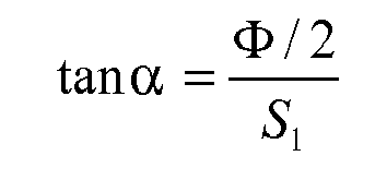
where Φ/2 is the half-diameter of the aforesaid lens. - Hence, it follows that, given a lens of diameter Φ and focal length f, in paraxial approximation the distance S0 of the light source from said lens determines the semidivergence α of the beam of rays leaving said lens. In the case of the advantageous embodiment described, the semidivergence α of the beam of rays emitted by the light-generating means 12a, 12b and leaving the
second surface 14b of theoptical module 14 may be, to a first approximation, evaluated in a similar way. - In a preferred embodiment each of the two
surfaces optical axis 16 of a portion of conical curve (for example, the arc of a circumference, the arc of a parabola, of the arc of a hyperbole) and the uniformity of lighting on theplane 15 is achieved in an approximate way. In another preferred embodiment, at least one of the twosurfaces 
optical module 14 on theplane 15 set at a distance do will be uniform. - In general terms, given the small size of the
indications 4 with respect to their distance do from thebase 5 on which the light-generating means 12a, 12b are set, thesurfaces module 14 can be simple portions of spherical caps, without the lack of uniformity introduced on the lighting profile being perceived as troublesome by the user. However, in the case where the extension of theindications 4 is approximately comparable to or greater than the distance do, then it is preferable for at least one of thesurfaces plane 15 and, consequently, any lack of uniformity of luminance of theindications 4 perceived by the user. - In a further embodiment, the
upper wall 3a of thehollow body 3 has at least one of its two faces (the outer face and/or the inner face) that is not smooth, or distinguished by a certain degree of surface roughness, in such a way that a beam of collimated light impinging upon it from a direction normal to the face itself will not traverse thewall 3a unperturbed, but rather will be diffused, i.e., its angular divergence will be increased, with a characteristic angle of diffusion δ. It is known that, when a light beam of divergence α traverses a wall of which at least one of the two faces is a diffusing surface and is characterized by an angle of diffusion δ, then the final divergence αf of said light beam leaving said wall can be, to a first approximation, determined as the quadratic sum of said initial divergence α and of said angle of diffusion δ, namely:
- The presence of at least one face that diffuses with an angle of diffusion δ enables the user to perceive the uniformity of lighting of the
indication 4 as uniformity of luminance. By appropriately combining the divergence α introduced by theoptical module 14 with the characteristic angle of diffusion δ introduced by the surface roughness of at least one of the two faces of thetop wall 3a it is possible to obtain, at output from thereference 4, a light beam of desired divergence αf and, consequently, obtain a reference that is uniformly illuminated with an angle of visibility αf. - In one embodiment, in the case where the light-generating means comprises at least two sources, as in the case exemplified in the figures, the latter can have a different colour or spectral peak of emission, in such a way that the
indication 4 will be perceived by the user with a different colouring according to whether just onesource - In on embodiment, one of the two
sources indication 4 and signal the position thereof, whilst the other of saidsources indication 4. - In a possible embodiment of the invention, different from the one exemplified in the figures, the
indication 4 is on an input or command element, such as a key that can be operated by the user, the body of which substantially corresponds with thebody 3, and operation of which is obtained according to known techniques, for example, with a mono-stable or bistable push-button system carried by the base 5: in this case, the identification of theindication 4 coincides with the identification of the command associated to the key and is carried out upon starting of the motor vehicle. In another embodiment, the identification of the key is performed whenever the key is depressed, in such a way that the on-board electronics CS will simultaneously record that pressure has been applied and identification of the command associated to the pressure applied. - Of course, without prejudice to the principle of the invention, the details of construction and the embodiments may vary widely with respect to what is described and illustrated herein purely by way of example, without thereby departing from the scope of the present invention as defined in the annexed claims.
- In the case of a user-interface device without back-lighting system, the
body 3 may also be a non-hollow body, it being sufficient for theconductive layer 10 and the insulatinglayer 9b having thewindows 11 and/or local portions 11' to be provided on its outer walls, according to what has been described previously. - It is then evident that, if need be, the
connectors 6 can be configured in such a way that thecontacts 7 will co-operate with the internal face of thewalls 3b, in which case it will be said internal face that is provided with theconductive layer 10 and insulatinglayer 9b, as well aswindows 11 and local portions 11' of the insulating layer. In order to increase the encoding possibilities, moreover, first and second contacts can be provided for being set up against, respectively, the outer face and the inner face of one ormore walls 3b, said faces being both provided with theconductive layer 10 and insulatinglayer 9b, as well as withwindows 11 and/or local portions 11'. - The
contacts 7 could also be associated directly to thesubstrate 5, i.e., without thecorresponding body connector 6, and come up from said substrate in a vertical direction. - Finally, it emerges clearly that the general shape of the body of the
indication elements 3, whether these are command keys or else just elements for signalling information, may be different from the one exemplified, even with a number of side walls different from the one exemplified, to which there may correspond respective connectors. It is likewise clear that the encoding means 9b, 10, 11, 11' described could possibly be present also on a single side wall of thebody 3, providing acorresponding connector 6 with an adequate number ofcontacts 7.
Claims (15)
- A user-interface device, which comprises:- a plurality of indication elements (3) for signalling of information and/or input of commands, each indication element (3) having an individual identity and including a visual indication (4);- a structure (2, 2a, 5) adapted for receiving the indication elements (3), the indication elements (3) being in particular mounted in a relocatable way on the structure (2, 2a, 5);wherein each indication element (3) has a body including at least one upper face (3a), provided with a corresponding visual indication (4), and one or more side faces (3b), and wherein the indication elements (3) comprise identification means (9b, 10, 11, 11') configured for co-operating with detection means (6, 7, CS) of the device (1), for identification of the identity of the indication elements (3),
characterized in that- the identification means (9b, 10, 11, 11') comprise a layer of electrically conductive material (10) on a respective said side face (3b), there being superimposed on the layer of electrically conductive material (10) a layer of electrically insulating material (9b);- the detection means (6, 7, CS) comprise one or more contact elements (7) set up against a respective said side face (6b);- the layer of electrically insulating material (9b) has one or more windows (11) for exposure of respective local portions of the underlying layer of electrically conductive material (10), each window (11) being obtained substantially at a respective contact element (7). - The device according to Claim 1, wherein operatively associated to at least one indication element (3) is a lighting system (12a, 12b, 14) comprising light-generating means (12a, 12b) in position set at the back of the body of the indication element (3).
- The device according to Claim 1 and/or Claim 2, wherein the contact elements (7) are at least in part elastically deformable and configured such that, in a respective condition of coupling with the body of the indication element (3), they are elastically pressed on the respective said side face (3b) of said body.
- The device according to Claim 2, wherein the lighting system comprises an optical module (14) made of transparent material associated to the light-generating means (12a, 12b) and configured for changing the direction of rays of light emitted by said generating means (12a, 12b), the optical module (14) being in particular housed in a cavity of the body of the indication element (3).
- The device according to Claim 4, wherein the optical module (14) is configured for generating a cone of rays of pre-set semidivergence α and a substantially uniform lighting profile of pre-set shape and dimensions in a plane (15) set at a pre-set distance (do) from a substrate (5) associated to which are the light-generating means (12a, 12b).
- The device according to at least one of Claims 2, 4 and 5, wherein the body of the indication element (3) is made of a transparent material and the corresponding upper face (3a) is coated by a layer of optically non-transmissive paint (14), formed in which is the respective visual indication (4).
- The device according to Claim 1, wherein the detection means (6, 7, CS) comprise a control system (CS) to which the interface device (1) is operatively connected, and wherein a succession of correspondences between contact elements (7) with respective windows (11) and/or local portions (11') of the electrically insulating layer (9b) provides a binary succession identifiable in a unique way by the control system (CS).
- The device according to at least one of the preceding claims, wherein the body of each indication element (3) has a plurality of said side faces (6b), extending on each of which is the layer of electrically conductive material (10) and the layer of electrically insulating material (9b), each of said side faces (6b) being provided with one or more of said windows (11), at least one said contact element (7) being set up against each of said side faces (6b).
- The device according to at least one of the preceding claims, wherein a number of contact elements (7) belong to one and the same connection member (6) defining a reception seat (7') for a lower region of a side wall (6b) of the body of one said indication element (3), one said side face belonging to said wall (6b), with the corresponding window or windows (11) that extends/extend at least in part in said lower region.
- The device according to at least one of Claims 2, 4, 5 and 6, wherein the light-generating means comprise at least two light sources (12a, 12b) having different colour or spectral emission peak.
- The device according to at least one of Claims 2, 4, 5, 6 and 10, wherein said upper face belongs to an upper wall (3a) of the body of the indication element (3) and at least one surface of said upper wall (3a) has a surface roughness configured such that a light beam impinging on said surface from a direction normal to the surface itself is diffused with an angle of diffusion.
- The device according to at least one of the preceding claims, wherein the body of at least one indication element (3) belongs to a key for input of commands or data.
- A method for providing a user-interface device (1) that comprises a plurality of indication elements (3) for signalling of information and/or input of commands, each indication element (3) having an individual identity and including a visual indication (4), the method comprising the operations of:a) providing a structure (2, 2a, 5) suitable for receiving the indication elements (3);b) providing the indication elements (3) with a respective body having an upper face (3a) and one or more side faces (3b);c) providing the indication elements (3) with identification means (9b, 10, 11, 11');d) providing the device (1) with detection means (6, 7, CS) configured for co-operating with the identification means (9b, 10, 11, 11') in order to identify the individual identity of the indication elements (3);e) mounting the indication elements (3) on the structure (2, 2a, 5), particularly in a relocatable way;
characterized in that- operation c) comprises the steps of:a1) depositing a layer of electrically conductive paint (10) on one or more side faces (3b) of said body;a2) depositing on the layer of electrically conductive paint (10) a layer of electrically insulating paint (9b);a3) forming in the layer of electrically insulating paint (9b) of one or more of said faces (3b) one or more windows (11), in order to expose respective local portions of the underlying layer of electrically conductive paint (10);- operation d) comprises the step of associating to the structure (2, 2a, 5) a plurality of contact elements (7) designed to co-operate with one or more of said side faces (6b) of said body; and- operation e) comprises the step of coupling said body to respective contact elements (7), in such a way that the contact elements (7) is set up against one or more of said side faces (6b) of said body, with one or more of said contact elements (7) substantially at one or more of said windows (11). - The method according to Claim 13, wherein the windows (11) are obtained via removal of portions of the layer of electrically insulating paint (9b), particularly via laser ablation or etching, so as to leave locally exposed the underlying layer of electrically conductive paint (10), or else depositing the layer of electrically insulating paint (9b) in a selective way, in order to coat the layer of electrically insulating paint (10) except for a desired pattern for said windows (11).
- The method according to Claim 13 or Claim 14, wherein a face (3a) of said body is coated with a layer of paint of a different colouring with respect to that of said body and the visual indication (4) is obtained via partial removal of said layer of paint of different colouring (9a), particularly via laser ablation or etching, according to a desired pattern, leaving the underlying material constituting said body exposed, or else by depositing the layer of paint of different colouring (9a) in a selective way in order to coat said face (3a) except for the pattern desired for the visual indication (4), where in particular:- said body is made of a transparent material,- said paint of different colouring (9a) is an optically non-transmissive paint; and- operatively associated to said body is a back-lighting system (12a, 12b, 14) comprising light-generating means (12a, 12b).
Priority Applications (8)
| Application Number | Priority Date | Filing Date | Title |
|---|---|---|---|
| EP09425049A EP2219198B1 (en) | 2009-02-11 | 2009-02-11 | Reconfigurable user interface device |
| AT09425049T ATE504073T1 (en) | 2009-02-11 | 2009-02-11 | RECONFIGURABLE USER INTERFACE |
| DE602009000991T DE602009000991D1 (en) | 2009-02-11 | 2009-02-11 | Reconfigurable user interface |
| US12/934,901 US8325469B2 (en) | 2009-02-11 | 2010-01-25 | Reconfigurable user-interface device |
| CN201310701627.5A CN103745864B (en) | 2009-02-11 | 2010-01-25 | Reconfigurable user's interface device |
| PCT/IB2010/050321 WO2010092498A1 (en) | 2009-02-11 | 2010-01-25 | Reconfigurable user-interface device |
| CN201080001563.2A CN102027558B (en) | 2009-02-11 | 2010-01-25 | Reconfigurable user-interface device |
| US13/693,027 US8749397B2 (en) | 2009-02-11 | 2012-12-03 | Reconfigurable user-interface device |
Applications Claiming Priority (1)
| Application Number | Priority Date | Filing Date | Title |
|---|---|---|---|
| EP09425049A EP2219198B1 (en) | 2009-02-11 | 2009-02-11 | Reconfigurable user interface device |
Publications (2)
| Publication Number | Publication Date |
|---|---|
| EP2219198A1 true EP2219198A1 (en) | 2010-08-18 |
| EP2219198B1 EP2219198B1 (en) | 2011-03-30 |
Family
ID=40735423
Family Applications (1)
| Application Number | Title | Priority Date | Filing Date |
|---|---|---|---|
| EP09425049A Active EP2219198B1 (en) | 2009-02-11 | 2009-02-11 | Reconfigurable user interface device |
Country Status (6)
| Country | Link |
|---|---|
| US (2) | US8325469B2 (en) |
| EP (1) | EP2219198B1 (en) |
| CN (2) | CN102027558B (en) |
| AT (1) | ATE504073T1 (en) |
| DE (1) | DE602009000991D1 (en) |
| WO (1) | WO2010092498A1 (en) |
Families Citing this family (2)
| Publication number | Priority date | Publication date | Assignee | Title |
|---|---|---|---|---|
| EP2219198B1 (en) * | 2009-02-11 | 2011-03-30 | C.R.F. Società Consortile per Azioni | Reconfigurable user interface device |
| US9213375B2 (en) * | 2012-09-06 | 2015-12-15 | Apple Inc. | Enclosure assembly and systems and methods for using the same |
Citations (2)
| Publication number | Priority date | Publication date | Assignee | Title |
|---|---|---|---|---|
| US20040155868A1 (en) | 2003-02-10 | 2004-08-12 | Hui Cheuk Fai Howard | Devices, apparatus and appliances with location reconfigurable input keys |
| US6891528B2 (en) | 2001-04-24 | 2005-05-10 | International Business Machines Corporation | Interchangeable keyboard with self defining keys |
Family Cites Families (7)
| Publication number | Priority date | Publication date | Assignee | Title |
|---|---|---|---|---|
| US4758701A (en) * | 1984-03-14 | 1988-07-19 | Allen-Bradley Company | Indicator light assembly for control panel |
| EP1054321A3 (en) * | 1999-05-21 | 2002-06-19 | Sony Corporation | Information processing method and apparatus |
| US6556183B1 (en) * | 2000-06-09 | 2003-04-29 | Nokia Mobile Phones Ltd. | Communications device having an interchangeable helmet user-interface |
| JP2005084460A (en) * | 2003-09-10 | 2005-03-31 | Seiko Epson Corp | Light guide body for indicator, and button switch, recorder and liquid jetting device equipped therewith |
| CN2864799Y (en) * | 2005-11-24 | 2007-01-31 | 新巨企业股份有限公司 | Keyboard with backlight structure |
| US8373664B2 (en) * | 2006-12-18 | 2013-02-12 | Cypress Semiconductor Corporation | Two circuit board touch-sensor device |
| EP2219198B1 (en) * | 2009-02-11 | 2011-03-30 | C.R.F. Società Consortile per Azioni | Reconfigurable user interface device |
-
2009
- 2009-02-11 EP EP09425049A patent/EP2219198B1/en active Active
- 2009-02-11 DE DE602009000991T patent/DE602009000991D1/en active Active
- 2009-02-11 AT AT09425049T patent/ATE504073T1/en not_active IP Right Cessation
-
2010
- 2010-01-25 CN CN201080001563.2A patent/CN102027558B/en not_active Expired - Fee Related
- 2010-01-25 WO PCT/IB2010/050321 patent/WO2010092498A1/en active Application Filing
- 2010-01-25 CN CN201310701627.5A patent/CN103745864B/en not_active Expired - Fee Related
- 2010-01-25 US US12/934,901 patent/US8325469B2/en not_active Expired - Fee Related
-
2012
- 2012-12-03 US US13/693,027 patent/US8749397B2/en not_active Expired - Fee Related
Patent Citations (2)
| Publication number | Priority date | Publication date | Assignee | Title |
|---|---|---|---|---|
| US6891528B2 (en) | 2001-04-24 | 2005-05-10 | International Business Machines Corporation | Interchangeable keyboard with self defining keys |
| US20040155868A1 (en) | 2003-02-10 | 2004-08-12 | Hui Cheuk Fai Howard | Devices, apparatus and appliances with location reconfigurable input keys |
Non-Patent Citations (1)
| Title |
|---|
| "CUSTOMIZABLE KEYS USING ADD-ON PLUGS", IBM TECHNICAL DISCLOSURE BULLETIN, IBM CORP. NEW YORK, US, vol. 33, no. 1B, 1 June 1990 (1990-06-01), pages 426 - 429, XP000122950, ISSN: 0018-8689 * |
Also Published As
| Publication number | Publication date |
|---|---|
| CN103745864A (en) | 2014-04-23 |
| EP2219198B1 (en) | 2011-03-30 |
| WO2010092498A1 (en) | 2010-08-19 |
| CN102027558B (en) | 2014-03-12 |
| US8325469B2 (en) | 2012-12-04 |
| CN103745864B (en) | 2016-08-17 |
| ATE504073T1 (en) | 2011-04-15 |
| US8749397B2 (en) | 2014-06-10 |
| DE602009000991D1 (en) | 2011-05-12 |
| CN102027558A (en) | 2011-04-20 |
| US20110026206A1 (en) | 2011-02-03 |
| US20130241740A1 (en) | 2013-09-19 |
Similar Documents
| Publication | Publication Date | Title |
|---|---|---|
| CN109383410B (en) | Luminous sign with radar function for vehicle | |
| US7129432B2 (en) | Lighted switch unit | |
| US7388167B2 (en) | Keyboard structure | |
| US5491313A (en) | Halo lighting for keypad switch assemblies | |
| US7967495B2 (en) | Scuff plate | |
| KR101278670B1 (en) | Display device and method, key, keyboard and electronic device using same | |
| CN102473023A (en) | Apparatus having closed and open configurations, and associated portable device, method and computer readable medium | |
| US10162095B2 (en) | Backlighting for a button assembly and method | |
| CN101779176A (en) | Illuminated keyboard and light guide for graphic symbols and method | |
| US8143541B2 (en) | Movable contact assembly including light inlet having plural grooves, and switch using the same | |
| EP2219198B1 (en) | Reconfigurable user interface device | |
| KR100667587B1 (en) | Keypad for portable appliance and thereof manufacturing method | |
| CN101414517A (en) | Switch | |
| CN103369892B (en) | Electronic device | |
| EP3432196B1 (en) | Sensing device and terminal device | |
| JP2001291458A (en) | Optical touch switch device | |
| US20090178906A1 (en) | Keypad panel assembly having arrays of micropores | |
| GB2419021A (en) | Control panel with back-lit graphic | |
| US6888079B2 (en) | Multifunctional pushbutton switch | |
| JP2007080763A (en) | Illuminated push-button switch cover member and method of manufacturing same | |
| US20120171414A1 (en) | Apparatus and Method for a User Input Element in an Electronic Device | |
| CN113133311A (en) | Vehicle mount with integrated functional elements | |
| CN212434526U (en) | Keyboard | |
| CN106409584B (en) | Luminous keyboard device | |
| GB2304233A (en) | Flat data entry keyboard |
Legal Events
| Date | Code | Title | Description |
|---|---|---|---|
| PUAI | Public reference made under article 153(3) epc to a published international application that has entered the european phase |
Free format text: ORIGINAL CODE: 0009012 |
|
| 17P | Request for examination filed |
Effective date: 20091013 |
|
| AK | Designated contracting states |
Kind code of ref document: A1 Designated state(s): AT BE BG CH CY CZ DE DK EE ES FI FR GB GR HR HU IE IS IT LI LT LU LV MC MK MT NL NO PL PT RO SE SI SK TR |
|
| AX | Request for extension of the european patent |
Extension state: AL BA RS |
|
| GRAP | Despatch of communication of intention to grant a patent |
Free format text: ORIGINAL CODE: EPIDOSNIGR1 |
|
| RIC1 | Information provided on ipc code assigned before grant |
Ipc: H01H 13/83 20060101AFI20101012BHEP |
|
| GRAS | Grant fee paid |
Free format text: ORIGINAL CODE: EPIDOSNIGR3 |
|
| GRAA | (expected) grant |
Free format text: ORIGINAL CODE: 0009210 |
|
| AK | Designated contracting states |
Kind code of ref document: B1 Designated state(s): AT BE BG CH CY CZ DE DK EE ES FI FR GB GR HR HU IE IS IT LI LT LU LV MC MK MT NL NO PL PT RO SE SI SK TR |
|
| REG | Reference to a national code |
Ref country code: GB Ref legal event code: FG4D |
|
| REG | Reference to a national code |
Ref country code: CH Ref legal event code: EP |
|
| AKX | Designation fees paid |
Designated state(s): AT BE BG CH CY CZ DE DK EE ES FI FR GB GR HR HU IE IS IT LI LT LU LV MC MK MT NL NO PL PT RO SE SI SK TR |
|
| REG | Reference to a national code |
Ref country code: IE Ref legal event code: FG4D |
|
| REF | Corresponds to: |
Ref document number: 602009000991 Country of ref document: DE Date of ref document: 20110512 Kind code of ref document: P |
|
| REG | Reference to a national code |
Ref country code: DE Ref legal event code: R096 Ref document number: 602009000991 Country of ref document: DE Effective date: 20110512 |
|
| REG | Reference to a national code |
Ref country code: NL Ref legal event code: VDEP Effective date: 20110330 |
|
| PG25 | Lapsed in a contracting state [announced via postgrant information from national office to epo] |
Ref country code: GR Free format text: LAPSE BECAUSE OF FAILURE TO SUBMIT A TRANSLATION OF THE DESCRIPTION OR TO PAY THE FEE WITHIN THE PRESCRIBED TIME-LIMIT Effective date: 20110701 Ref country code: SE Free format text: LAPSE BECAUSE OF FAILURE TO SUBMIT A TRANSLATION OF THE DESCRIPTION OR TO PAY THE FEE WITHIN THE PRESCRIBED TIME-LIMIT Effective date: 20110330 Ref country code: LT Free format text: LAPSE BECAUSE OF FAILURE TO SUBMIT A TRANSLATION OF THE DESCRIPTION OR TO PAY THE FEE WITHIN THE PRESCRIBED TIME-LIMIT Effective date: 20110330 Ref country code: LV Free format text: LAPSE BECAUSE OF FAILURE TO SUBMIT A TRANSLATION OF THE DESCRIPTION OR TO PAY THE FEE WITHIN THE PRESCRIBED TIME-LIMIT Effective date: 20110330 Ref country code: HR Free format text: LAPSE BECAUSE OF FAILURE TO SUBMIT A TRANSLATION OF THE DESCRIPTION OR TO PAY THE FEE WITHIN THE PRESCRIBED TIME-LIMIT Effective date: 20110330 |
|
| LTIE | Lt: invalidation of european patent or patent extension |
Effective date: 20110330 |
|
| PG25 | Lapsed in a contracting state [announced via postgrant information from national office to epo] |
Ref country code: AT Free format text: LAPSE BECAUSE OF FAILURE TO SUBMIT A TRANSLATION OF THE DESCRIPTION OR TO PAY THE FEE WITHIN THE PRESCRIBED TIME-LIMIT Effective date: 20110330 Ref country code: FI Free format text: LAPSE BECAUSE OF FAILURE TO SUBMIT A TRANSLATION OF THE DESCRIPTION OR TO PAY THE FEE WITHIN THE PRESCRIBED TIME-LIMIT Effective date: 20110330 Ref country code: SI Free format text: LAPSE BECAUSE OF FAILURE TO SUBMIT A TRANSLATION OF THE DESCRIPTION OR TO PAY THE FEE WITHIN THE PRESCRIBED TIME-LIMIT Effective date: 20110330 Ref country code: CY Free format text: LAPSE BECAUSE OF FAILURE TO SUBMIT A TRANSLATION OF THE DESCRIPTION OR TO PAY THE FEE WITHIN THE PRESCRIBED TIME-LIMIT Effective date: 20110330 Ref country code: NO Free format text: LAPSE BECAUSE OF FAILURE TO SUBMIT A TRANSLATION OF THE DESCRIPTION OR TO PAY THE FEE WITHIN THE PRESCRIBED TIME-LIMIT Effective date: 20110630 |
|
| PG25 | Lapsed in a contracting state [announced via postgrant information from national office to epo] |
Ref country code: BE Free format text: LAPSE BECAUSE OF FAILURE TO SUBMIT A TRANSLATION OF THE DESCRIPTION OR TO PAY THE FEE WITHIN THE PRESCRIBED TIME-LIMIT Effective date: 20110330 |
|
| PG25 | Lapsed in a contracting state [announced via postgrant information from national office to epo] |
Ref country code: PT Free format text: LAPSE BECAUSE OF FAILURE TO SUBMIT A TRANSLATION OF THE DESCRIPTION OR TO PAY THE FEE WITHIN THE PRESCRIBED TIME-LIMIT Effective date: 20110801 Ref country code: EE Free format text: LAPSE BECAUSE OF FAILURE TO SUBMIT A TRANSLATION OF THE DESCRIPTION OR TO PAY THE FEE WITHIN THE PRESCRIBED TIME-LIMIT Effective date: 20110330 |
|
| PG25 | Lapsed in a contracting state [announced via postgrant information from national office to epo] |
Ref country code: RO Free format text: LAPSE BECAUSE OF FAILURE TO SUBMIT A TRANSLATION OF THE DESCRIPTION OR TO PAY THE FEE WITHIN THE PRESCRIBED TIME-LIMIT Effective date: 20110330 Ref country code: ES Free format text: LAPSE BECAUSE OF FAILURE TO SUBMIT A TRANSLATION OF THE DESCRIPTION OR TO PAY THE FEE WITHIN THE PRESCRIBED TIME-LIMIT Effective date: 20110711 Ref country code: SK Free format text: LAPSE BECAUSE OF FAILURE TO SUBMIT A TRANSLATION OF THE DESCRIPTION OR TO PAY THE FEE WITHIN THE PRESCRIBED TIME-LIMIT Effective date: 20110330 Ref country code: CZ Free format text: LAPSE BECAUSE OF FAILURE TO SUBMIT A TRANSLATION OF THE DESCRIPTION OR TO PAY THE FEE WITHIN THE PRESCRIBED TIME-LIMIT Effective date: 20110330 Ref country code: IS Free format text: LAPSE BECAUSE OF FAILURE TO SUBMIT A TRANSLATION OF THE DESCRIPTION OR TO PAY THE FEE WITHIN THE PRESCRIBED TIME-LIMIT Effective date: 20110730 |
|
| PG25 | Lapsed in a contracting state [announced via postgrant information from national office to epo] |
Ref country code: NL Free format text: LAPSE BECAUSE OF FAILURE TO SUBMIT A TRANSLATION OF THE DESCRIPTION OR TO PAY THE FEE WITHIN THE PRESCRIBED TIME-LIMIT Effective date: 20110330 |
|
| PLBE | No opposition filed within time limit |
Free format text: ORIGINAL CODE: 0009261 |
|
| STAA | Information on the status of an ep patent application or granted ep patent |
Free format text: STATUS: NO OPPOSITION FILED WITHIN TIME LIMIT |
|
| PG25 | Lapsed in a contracting state [announced via postgrant information from national office to epo] |
Ref country code: PL Free format text: LAPSE BECAUSE OF FAILURE TO SUBMIT A TRANSLATION OF THE DESCRIPTION OR TO PAY THE FEE WITHIN THE PRESCRIBED TIME-LIMIT Effective date: 20110330 |
|
| 26N | No opposition filed |
Effective date: 20120102 |
|
| REG | Reference to a national code |
Ref country code: DE Ref legal event code: R097 Ref document number: 602009000991 Country of ref document: DE Effective date: 20120102 |
|
| PG25 | Lapsed in a contracting state [announced via postgrant information from national office to epo] |
Ref country code: MC Free format text: LAPSE BECAUSE OF NON-PAYMENT OF DUE FEES Effective date: 20120229 |
|
| REG | Reference to a national code |
Ref country code: IE Ref legal event code: MM4A |
|
| PG25 | Lapsed in a contracting state [announced via postgrant information from national office to epo] |
Ref country code: IE Free format text: LAPSE BECAUSE OF NON-PAYMENT OF DUE FEES Effective date: 20120211 |
|
| PG25 | Lapsed in a contracting state [announced via postgrant information from national office to epo] |
Ref country code: MK Free format text: LAPSE BECAUSE OF FAILURE TO SUBMIT A TRANSLATION OF THE DESCRIPTION OR TO PAY THE FEE WITHIN THE PRESCRIBED TIME-LIMIT Effective date: 20110330 |
|
| PG25 | Lapsed in a contracting state [announced via postgrant information from national office to epo] |
Ref country code: BG Free format text: LAPSE BECAUSE OF FAILURE TO SUBMIT A TRANSLATION OF THE DESCRIPTION OR TO PAY THE FEE WITHIN THE PRESCRIBED TIME-LIMIT Effective date: 20110630 |
|
| PG25 | Lapsed in a contracting state [announced via postgrant information from national office to epo] |
Ref country code: MT Free format text: LAPSE BECAUSE OF FAILURE TO SUBMIT A TRANSLATION OF THE DESCRIPTION OR TO PAY THE FEE WITHIN THE PRESCRIBED TIME-LIMIT Effective date: 20110330 |
|
| REG | Reference to a national code |
Ref country code: CH Ref legal event code: PL |
|
| GBPC | Gb: european patent ceased through non-payment of renewal fee |
Effective date: 20130211 |
|
| PG25 | Lapsed in a contracting state [announced via postgrant information from national office to epo] |
Ref country code: LI Free format text: LAPSE BECAUSE OF NON-PAYMENT OF DUE FEES Effective date: 20130228 Ref country code: CH Free format text: LAPSE BECAUSE OF NON-PAYMENT OF DUE FEES Effective date: 20130228 |
|
| PG25 | Lapsed in a contracting state [announced via postgrant information from national office to epo] |
Ref country code: GB Free format text: LAPSE BECAUSE OF NON-PAYMENT OF DUE FEES Effective date: 20130211 |
|
| PG25 | Lapsed in a contracting state [announced via postgrant information from national office to epo] |
Ref country code: TR Free format text: LAPSE BECAUSE OF FAILURE TO SUBMIT A TRANSLATION OF THE DESCRIPTION OR TO PAY THE FEE WITHIN THE PRESCRIBED TIME-LIMIT Effective date: 20110330 |
|
| PG25 | Lapsed in a contracting state [announced via postgrant information from national office to epo] |
Ref country code: LU Free format text: LAPSE BECAUSE OF NON-PAYMENT OF DUE FEES Effective date: 20120211 |
|
| PG25 | Lapsed in a contracting state [announced via postgrant information from national office to epo] |
Ref country code: HU Free format text: LAPSE BECAUSE OF FAILURE TO SUBMIT A TRANSLATION OF THE DESCRIPTION OR TO PAY THE FEE WITHIN THE PRESCRIBED TIME-LIMIT Effective date: 20090211 |
|
| REG | Reference to a national code |
Ref country code: FR Ref legal event code: PLFP Year of fee payment: 8 |
|
| REG | Reference to a national code |
Ref country code: FR Ref legal event code: PLFP Year of fee payment: 9 |
|
| PGFP | Annual fee paid to national office [announced via postgrant information from national office to epo] |
Ref country code: FR Payment date: 20170224 Year of fee payment: 9 |
|
| PGFP | Annual fee paid to national office [announced via postgrant information from national office to epo] |
Ref country code: IT Payment date: 20170214 Year of fee payment: 9 |
|
| PGFP | Annual fee paid to national office [announced via postgrant information from national office to epo] |
Ref country code: DE Payment date: 20170428 Year of fee payment: 9 |
|
| REG | Reference to a national code |
Ref country code: DE Ref legal event code: R119 Ref document number: 602009000991 Country of ref document: DE |
|
| REG | Reference to a national code |
Ref country code: FR Ref legal event code: ST Effective date: 20181031 |
|
| PG25 | Lapsed in a contracting state [announced via postgrant information from national office to epo] |
Ref country code: DE Free format text: LAPSE BECAUSE OF NON-PAYMENT OF DUE FEES Effective date: 20180901 |
|
| PG25 | Lapsed in a contracting state [announced via postgrant information from national office to epo] |
Ref country code: IT Free format text: LAPSE BECAUSE OF NON-PAYMENT OF DUE FEES Effective date: 20180211 Ref country code: FR Free format text: LAPSE BECAUSE OF NON-PAYMENT OF DUE FEES Effective date: 20180228 |