EP2223674A1 - Inflatable head or forearm support device - Google Patents
Inflatable head or forearm support device Download PDFInfo
- Publication number
- EP2223674A1 EP2223674A1 EP10250313A EP10250313A EP2223674A1 EP 2223674 A1 EP2223674 A1 EP 2223674A1 EP 10250313 A EP10250313 A EP 10250313A EP 10250313 A EP10250313 A EP 10250313A EP 2223674 A1 EP2223674 A1 EP 2223674A1
- Authority
- EP
- European Patent Office
- Prior art keywords
- compartments
- large side
- side compartments
- compartment
- patient
- Prior art date
- Legal status (The legal status is an assumption and is not a legal conclusion. Google has not performed a legal analysis and makes no representation as to the accuracy of the status listed.)
- Granted
Links
Images


Classifications
-
- A—HUMAN NECESSITIES
- A61—MEDICAL OR VETERINARY SCIENCE; HYGIENE
- A61G—TRANSPORT, PERSONAL CONVEYANCES, OR ACCOMMODATION SPECIALLY ADAPTED FOR PATIENTS OR DISABLED PERSONS; OPERATING TABLES OR CHAIRS; CHAIRS FOR DENTISTRY; FUNERAL DEVICES
- A61G7/00—Beds specially adapted for nursing; Devices for lifting patients or disabled persons
- A61G7/05—Parts, details or accessories of beds
- A61G7/057—Arrangements for preventing bed-sores or for supporting patients with burns, e.g. mattresses specially adapted therefor
-
- A—HUMAN NECESSITIES
- A47—FURNITURE; DOMESTIC ARTICLES OR APPLIANCES; COFFEE MILLS; SPICE MILLS; SUCTION CLEANERS IN GENERAL
- A47G—HOUSEHOLD OR TABLE EQUIPMENT
- A47G9/00—Bed-covers; Counterpanes; Travelling rugs; Sleeping rugs; Sleeping bags; Pillows
- A47G9/10—Pillows
- A47G9/1027—Details of inflatable pillows
-
- A—HUMAN NECESSITIES
- A61—MEDICAL OR VETERINARY SCIENCE; HYGIENE
- A61G—TRANSPORT, PERSONAL CONVEYANCES, OR ACCOMMODATION SPECIALLY ADAPTED FOR PATIENTS OR DISABLED PERSONS; OPERATING TABLES OR CHAIRS; CHAIRS FOR DENTISTRY; FUNERAL DEVICES
- A61G7/00—Beds specially adapted for nursing; Devices for lifting patients or disabled persons
- A61G7/05—Parts, details or accessories of beds
- A61G7/065—Rests specially adapted therefor
- A61G7/07—Rests specially adapted therefor for the head or torso, e.g. special back-rests
- A61G7/072—Rests specially adapted therefor for the head or torso, e.g. special back-rests for the head only
-
- A—HUMAN NECESSITIES
- A61—MEDICAL OR VETERINARY SCIENCE; HYGIENE
- A61G—TRANSPORT, PERSONAL CONVEYANCES, OR ACCOMMODATION SPECIALLY ADAPTED FOR PATIENTS OR DISABLED PERSONS; OPERATING TABLES OR CHAIRS; CHAIRS FOR DENTISTRY; FUNERAL DEVICES
- A61G7/00—Beds specially adapted for nursing; Devices for lifting patients or disabled persons
- A61G7/05—Parts, details or accessories of beds
- A61G7/065—Rests specially adapted therefor
- A61G7/075—Rests specially adapted therefor for the limbs
Landscapes
- Health & Medical Sciences (AREA)
- General Health & Medical Sciences (AREA)
- Otolaryngology (AREA)
- Pulmonology (AREA)
- Nursing (AREA)
- Life Sciences & Earth Sciences (AREA)
- Animal Behavior & Ethology (AREA)
- Public Health (AREA)
- Veterinary Medicine (AREA)
- Invalid Beds And Related Equipment (AREA)
- Axle Suspensions And Sidecars For Cycles (AREA)
Abstract
a) the unfolded position for forming a head support in which a patient's neck (17) can be supported by said third compartment (3), wherein the two large side compartments control the sideways tilting of the head and wherein the back of the patient's head is suspended without contacting said support plane (P), and
b) a folded position for forming a forearm (13) support in which the patient's forearm (13) can rest on said top surfaces of the two large side compartments which are in proximity to each other with the patient's elbow (13-3) suspended in space without contacting the third surfaces and the fifth surfaces of the large side compartments, and wherein the patient's hand (13-1) can be inserted in an open space (7-3) between the two large side compartments and the third compartment and can grasp hold of said third compartment.
Description
- The present invention relates to an inflatable head or forearm support device. More particularly, the present invention relates to a support device comprising cells or compartments designed to be inflated with air.
- Hence the present invention relates to the field of mattress or cushion-type support devices for supporting the body or a part of the body of a reclining person.
- Known support devices of this type comprise inflatable elements, generally in the form of essentially sausage-shaped cylinders disposed side by side and which are used in particular as mattresses to form an inflatable supporting layer on which an individual can be reclined and supported in optimum comfortable conditions, in particular for therapeutic purposes.
- Mattresses referred to as therapeutic mattresses consisting of cells inflated with air, particularly sausage-shaped cells extending crossways relative to the longitudinal axis of the bed on which the mattress is intended to be used, wherein said cells are filled with air by means of an air pressure regulator system making it possible, as needed, to vary the air pressure in the cells in different mattress zones relative to the parts of the body exerting pressure on said mattress zones in such a way as to homogenize the interface pressure on the various parts of the body, are also known.
- The main purpose of these therapeutic mattresses, which are described, for example, in French patent no.
07 55812 - Such mattresses, enable the filling of the inflatable elements in the various mattress zones and hence the pressure to be controlled individually, in order to produce an interface pressure distribution adapted to each part of the patient's body, thanks to a mechanism for controlling the inflation/deflation of the cells.
- The aim of these control mechanisms is not only to ensure the patient's optimum comfort but also to ensure optimum vascularization of the patient's body by homogenizing the pressure exerted by the mattress on the different parts of the patient's body.
- The use of a plurality of sausage-shaped cylinders disposed side by side in combination with a system for controlling the inflation of the cells makes it possible to homogenize the pressures exerted locally by the mattress surface at various points on the body relative to the morphology and the position of the patients, and thus avoid or reduce the risks of decubitus sores forming in the at-risk zones of the body, such as, in particular, the sacrum and the heels.
- A support device especially suited for reducing the formation of bedsores in the region of the feet is described in
US-5,952,872 . - An inflatable cushion having different cells disposed side by side longitudinally with lateral cells greater in height so as to provide a wedging of the head in a channel is described in
WO 2006/043861 . - The elbow and the forearm are also zones that are very likely to develop complications, in particular bedsores, because they consist of numerous bony protuberances and they are cited in studies on the prevalence of nosocomial infections.
- Elevating the patient's chest by tilting the back rest at the head end of the mattress on which the patient is reclining, particularly after a prolonged period of bed rest, results in a position that quickly becomes uncomfortable for the patient and leads to edema because the forearm and the hand are poorly vascularized, and the arm is in a lower position relative to the heart.
- Furthermore, it is often necessary to position the forearm with the inside facing upwards for drawing blood or inserting a catheter.
- The present invention provides a support device for the forearm or head of a patient comprising an inflatable plastic envelope forming two larger side compartments each having, in the inflated state and an unfolded position, first, second, third and fourth side surfaces and a fifth, bottom, surface and a sixth, top, surface, and one smaller third compartment in the shape of a tubular sleeve positioned crosswise between the side compartments, characterized in that the two large side compartments are symmetrically disposed relative to a first vertical median plane extending in a longitudinal direction, each of the large side compartments having a first side surface at a first longitudinal end and a second side surface at a second longitudinal end; in that the two large side compartments are joined together by the third compartment which interconnects opposing third side surfaces of the large side compartments, the third compartment being located near said first longitudinal end of the large side compartments, and having a second vertical plane of symmetry extending perpendicular to said first plane of symmetry and to said longitudinal direction in that said second surfaces each cooperate with or each comprise first connection elements capable of releasably engaging with each other so as to join said second side surfaces of the two large side compartments together, the two large side compartments and the third small crosswise compartment thus being able to assume the following two positions with the device positioned on a horizontal planar support P in its inflated state:
- a) the unfolded position for forming a head support in which the first connection means are not engaged and a patient's neck can be supported by the third compartment, with the two large side compartments controlling sideways tilting of the head and without the back of the patient's head, contacting said support plane and
- b) a folded position for forming a forearm support in which said first connection elements are engaged and the two large side compartments are in a folded position, in which the second surfaces are in close contact and said third and fourth surfaces of said large compartments become the top and bottom surfaces, respectively, of said large compartments and said first, said second, said fifth and said sixth surfaces become the inner and outer side surfaces, respectively, of said large compartments, and portions of said fifth surfaces of the two large compartments between the top surfaces formed by said third surfaces form a channel, and the ends of said third surfaces are bridged by said third compartment in such a way that a patient's forearm can rest on said third surfaces of the two large side compartments with the patient's elbow suspended in space without contacting the third surfaces and the fifth surfaces of the large side compartments, and wherein the patient's hand can be inserted in an open space between the two large side compartments and the third compartment and can grasp hold of said third compartment.
- Preferably:
- a) in said unfolded position for forming a head support, the section lines in a third median horizontal plane of said first and second side surfaces are parallel to said second plane of symmetry, wherein said section lines of said second side surfaces have a length shorter than that of the section lines of the first surfaces, wherein each of the two large side compartments has a first trapezoidal shape in the third median horizontal plane, wherein said third side surfaces and the third compartment delineate a first open space of second trapezoidal shape in this third plane, wherein the third compartment has a top surface lower than said fifth top surfaces at said first longitudinal end of the large side compartments, and
- b) in the folded position for forming a forearm support, portions of said fifth surfaces of the two large compartments extending from said second surfaces are in close contact with each other, and the remaining portions up to said first surfaces are progressively spaced apart in such a way that the fifth surfaces form a second open space between them, with a V-shaped longitudinal section, in a third plane parallel to the support plane, wherein the space between the top surfaces constituted by said third surfaces forms the channel above the close contact portions of the fifth surfaces adjacent said second longitudinal end of said large side compartments, wherein each third surface of the large side compartments in the inflated state has a curved, convex cross-section, and the ends of said third surfaces as well as the end of said second open space beside the first longitudinal ends of the large side compartments are spaced apart from each other and bridged by the third compartment which interconnects the third surfaces.
- The support device is designed to rest on a horizontal mattress on which the patient is seated, reclined on a bed with his/her chest elevated, with the bottom surfaces of the two large side compartments resting on said mattress.
- In said folded position for forming a forearm support, because the length of the first surfaces is greater than the length of the second surfaces in a third horizontal plane, said large side compartments have a height toward their first end that is greater than the height at their second longitudinal end. Hence, when the device is in the forearm support position, the elbow is at a lower elevation than the hand when the latter is engaged above or below the third compartment.
- In other words, in said folded forearm support position, the third surfaces of the two large side compartments are inclined relative to the support plane on which rest said bottom surfaces at an upward slope from said second surfaces to said first surfaces of the large side compartments and hence to said third compartment.
- The device when used as a forearm support makes it possible to relieve interface pressure on the elbow and on the forearm via the channel shape, because the elbow and the bottom surface of the forearm are suspended in space above the interconnection zone or line of contact of the fifth surfaces of the two large compartments, with the elbow and the forearm supported on each side by the convex, curved top rims of the fifth surfaces joining up with the third surfaces, which also have convex cross-sections.
- The channel of the forearm support device of the invention is formed on one hand by the line of contact between the fifth surfaces of the two large side compartments, and on the other hand by the progressive increased width between the top rims of the fifth surfaces of the two large compartments above the line of contact, as well as by the progressive widening between the fifth surfaces above the end of said line of contact forming a longitudinal sectional channel, of second trapezoidal shape. This channel thus makes it possible to wedge the forearm and, if need be, prevent it from pivoting sideways, hence facilitating the drawing of blood and the possible insertion of a catheter.
- Furthermore, said third compartment forms a handle overhanging and joining up with said third surfaces when said first connection elements are cooperating with each other and when the compartments are inflated, and with the two large compartments folded against each other. Hence the device makes it possible to support the forearm, the elbow being wedged in said channel, while enabling the hand to be held between the third surfaces of the two large compartments and the bottom surface of the third compartment. The hand can be inserted above said third surfaces or preferably below said third compartment in such a way that it is possible to grasp hold of said third compartment with the hand turned with its inner surface facing upwards. This position allows easy access to the wrist for drawing blood and the possible insertion of catheters by immobilizing the forearm in the channel and the hand between the handle and the third surfaces of the large side compartments.
- The same handle thus serves as a handhold, so also enabling the device to be used as a kinesiotherapy tool for the functional rehabilitation of the flexor and tensor muscles of the hand, fingers and wrist.
- Furthermore, the forearm support device prevents the development of complications linked to poor vascularization by elevating the forearm and by aligning the axis of the forearm perpendicular to the torso. Plus, in this position the elbow support device makes it possible to keep the forearm at the same elevation as the heart, thus facilitating the vascularization of the end of the hand.
- The forearm support device can also serve as a lateral wedging mechanism and cushioning zone between the patient's body, particularly between the patient's thighs, and the side rails of the bed.
- In the unfolded position said third compartment is capable of supporting a patient's neck, with the patient's chest and head wedged between and against the two side compartments, and the sides of the chest can be wedged against the third surfaces of the two side compartments.
- The device, thanks to its horseshoe shape when it is unfolded and flatly positioned for supporting the neck, thus makes it possible to wedge the patient's head comfortably while leaving the neck zone free. An unobstructed access to the neck while keeping the head wedged is very advantageous for an intubated patient, a patient on a respirator and/or a patient needing other types of care via this zone.
- Hence the unfolded configuration of the support device has the advantage of being able to allow good support of the head in various positions. In particular, the head is supported in the vicinity of the neck or cheek by the third compartment, with the skull then tilted rearwards and the chin and the throat, in contrast, tilted upwards and perhaps sideways, this position making it easier to insert a tube in the trachea of a patient reclining on a mattress.
- This configuration of the head support device is also useful for washing the patient's head and hair or for performing other healthcare tasks with a pan placed under the back of the patient's head.
- Controlling the position of the head in terms of sideways or rearwards pivoting, however, is mainly advantageous for avoiding excessive pressure on the patient's skin, which can lead to the formation of bedsores, and/or for treating said bedsores in the occipital and frontal regions and on the back, respectively, of the patient's head.
- A device capable of being inflated with air as described has advantages over the synthetic fabric or foam pillows generally used in hospital beds. Firstly, the device is much lighter and less bulky when it is stored in its deflated state. Furthermore, it is possible to manufacture such devices from a simple envelope made of plastic or other impermeable synthetic material, hence the manufacturing cost is considerably lower compared to synthetic fabric or foam-filled pillows. Last but not least, the expense of using such devices is considerably reduced because the device can be washed between two uses and hence reused for different patients, in contrast to foam pillows in particular. Moreover, foam or fabric materials are particularly hard to sterilize and therefore cannot be used for different patients.
- The fact that the device is capable of being inflated with air is advantageous in many respects.
On one hand, the device can be manufactured from a plastic envelope, which makes it less bulky in the deflated state, economical to manufacture and to use because since the device is washable, it can be reused for different patients. Furthermore, the comfort of the device can be adjusted by controlling the air pressure inside of it. In addition, it can be hooked up to the compressed air supply and pressure regulation system of a therapeutic mattress formed of inflatable cells. - Preferably, the section lines of said fourth surfaces in a median horizontal plane are disposed in said longitudinal direction XX' of said large side compartments, approximately 90° relative to the section lines in the median horizontal plane of said first and second surfaces of said large side compartments which are disposed in the perpendicular direction YY'.
- By "section line of a surface in a median horizontal plane" is meant the straight line or segment of intersection between said surface and a median horizontal plane, i.e., halfway up said surface.
- Preferably also, in said unfolded head support position, said median horizontal section plane is a common median plane of the large side compartments and of the third compartment, the extremes of said third compartment extend approximately halfway up said large side compartments, and a bottom surface of said third compartment is positioned above the support plane.
- In this embodiment, it is also understood that the extremities of said third compartment extend approximately to mid-width of said third surfaces when the device is in the folded forearm support position.
- The first connection elements may compromise zippers or Velcro positioned at the center of the second surfaces and spanning their length in the direction perpendicular to the longitudinal direction of the two large side compartments.
- It will be understood that said perpendicular direction is a horizontal direction when the device is in the unfolded position and that it is a vertical direction when the device is in the folded, forearm support position.
- Preferably the large compartments having second connection elements capable of keeping said first longitudinal ends in the longitudinal direction of said fourth surfaces of said large side compartments at a given distance apart in the folded forearm support position.
- Use of the device in its so-called folded forearm support position is achieved by the first connection elements, with the ends of the two large side compartments being brought in proximity to each other in the vicinity of the second surfaces, and that this is done by folding the two large side compartments approximately 90°. This folding, however, is reinforced if the first connection elements are complemented by second connection elements.
- More particularly, the second connection elements may be located near the common end of said first, fourth and fifth surfaces of each of the two large side compartments, and said second connection elements make it possible to adjust the distance between said common ends of each of the two large compartments.
- The ends of said third surfaces adjacent said first longitudinal ends of the two large side compartments are brought in proximity to each other from a distance equal at most to the length of the third compartment.
- It will be understood that, in the so-called folded position for forming a forearm support when said second connection elements are not used, the fourth surfaces of the large compartments are spaced further apart from each other in the vicinity of their first ends (the end beside the first surfaces) than the ends of the third surfaces. As a result, when the second connection elements are not used, the section lines in said second vertical median plane of said fifth surfaces are angled with respect to the first vertical median plane of symmetry of the two large side compartments relative to each other, being in closer proximity to each other toward the third surfaces than toward the fourth surfaces. Moreover, the sixth surfaces or outer side surfaces are inclined at a greater angle than the fifth surfaces.
- It is possible to adjust the height of the device at the first longitudinal ends of said two large compartments and to raise the height of said third compartment by bringing those ends towards each other by adjusting the length of the second connection elements. The effect of this will be to reduce the angle of the section lines of the fifth and sixth side surfaces of the two large side sectional compartments in the second vertical median plane of the third compartment.
- This adjustment of the height of the device at the first longitudinal ends of the two large side compartments is simultaneous with the adjustment of the width of the device at the first ends of said fourth surfaces of the two side compartments.
- It will be understood that the device when used as a forearm support has a maximum height when the second connection elements are adjusted in such a way as to provide a minimum distance between the first surfaces of the two large side compartments corresponding, in the region of the fourth surfaces, approximately to the distance between the third surfaces at the first ends of the two large side compartments. It is likewise understood that if the second connection elements are not engaged, said first ends of said fourth surfaces of the two large side compartments will obviously move a maximum distance apart from each other.
- This adjustment is advantageous, either as making it possible to elevate the patient's hand to the same height as the patient's heart and/or for the wedging of the device between the patient and the side rails of the hospital bed on which he/she is resting.
- Preferably said two large side compartments communicate with each other by means of said third compartment thus forming a single cell, with a single inflation valve stem, and further preferably a single deflation valve stem disposed on a sixth surface near its interconnection with a second surface and a fourth surface.
- Said inflation/deflation valve stems thus do not bother the patient, as they are located beside an outer side surface and the ends of the two large compartments, said ends being in proximity to each other when the device is in the folded position for forming a forearm support and corresponding to the rim of the top surfaces of each of the two side compartments remotest from the third compartment supporting the neck when the device is in the unfolded position for forming a head support.
- In an advantageous embodiment, the device has a cover with a shape of the three compartments of the inflatable envelope, with said first connection elements provided on the portion of the cover facing the portions of the inflatable envelope corresponding to the second surfaces of the large side compartments, and said cover has an opening equipped with releaseable closing elements enabling the introduction and confinement of said inflatable envelope in the cover.
- The cover will have openings for the inflation or deflation valve stems if provided.
- With the cover embodiment, second connection elements may be provided on the portion of the cover facing the portion of the inflatable envelope corresponding to the longitudinal ends of said fourth surfaces of said large side compartments, preferably near the common ends of said first and fourth surfaces.
- Advantageously, said second connection elements are elements suitable for adjusting the distance between said first ends of the two large side compartments and comprise at least one strap fastened to each end, wherein said strap or straps is/are equipped with complementary mutual fastening elements and wherein the length of at least one strap is adjustable.
- The device may be formed from a single inflatable envelope made of PVC or polyurethane film or fabric impregnated with PVC or polyurethane or two films of said plastic or fabric materials assembled together, preferably by welding along lines delimiting the large compartments and the third compartment in the unfolded, flat position.
- The surface of the envelope is easily cleaned with standard cleansers, or it can be uncovered and machine-washed.
- Advantageously, the device can be connected to a therapeutic mattress via a simple quick coupler for supplying air, particularly at the same regulated pressures as for the mattress or other support. It can also be inflated by a separate air supply and used separately.
- Preferably the device is pneumatically connected to a device for supplying compressed air to and regulating the air pressure in a therapeutic mattress formed of inflatable cells on which the device is resting, or the device is pneumatically connected to an air outlet valve of such a mattress
- The present invention at least in the preferred embodiments provides a universal device solving the problems discussed above and, in particular, capable of acting as both a pillow that not only provides additional means for fighting against the formation of bedsores, but also facilitates the necessary head and neck movements for interventions by healthcare personnel, more particularly in the vicinity of the head, and a forearm support that is capable of resolving the problems of bedsore formation and poor vascularization of the patient, as well as the problem of immobilizing the forearm discussed previously.
- The invention will now be further described by way of example with reference to the accompanying drawings, in which:
-
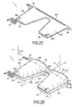
Figures 1A and 1B show a support device of the invention in the unfolded position on a plane P in the deflated state (figure 1A ) and in the inflated state (figure 1B ). -
Figures 1C and 1D show the support device offigure 1B , folded in the forearm or elbow support position. -
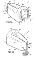
Figures 2A-2D show an inflatable envelope (figure 2A ) and a cover equipped with first and second connection elements, wherein said cover is capable of accommodating said inflatable envelope consisting of two large side compartments 2-3 and athird compartment 4 for forming a head support device after closure (figure 2C ) and after inflation (figure 2D ). -
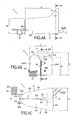
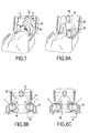
Figures 3A and 3B show perspective views of the front (figure 3A ) and the back (figure 3B ) of a device of the invention in the folded, forearm support position. -
Figure 4A is a side view of the device offigures 3A and 3B . -
Figure 4B is a back view of the device offigures 3A-3B . -
Figure 4C shows a view from above of the device offigures 3A-3B . -
Figure 5A is a cutaway view along line AA offigure 4A . -
Figure 5B is a cutaway view along line BB offigure 4B . -
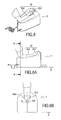
Figure 6 is a view of a forearm in position on a forearm support device of the invention. -
Figure 6A is a side view. -
Figure 6B is a cutaway view along line CC offigure 6A . -
Figure 7 is a view of the support device of the invention being used as a head support. -
Figures 8A, 8B and 8C are views of the support device of the invention being used as a forearm support by a patient on a hospital bed. - In
figure 1A , asupport device 1 is shown in a deflated position and flat on a planar support P.
The device comprises a single plastic envelope having the following three intercommunicating compartments: twolarge side compartments third compartment 4. - The two
large side compartments - their large base is constituted by a first side 2-1, 3-1 extending in the direction YY' perpendicular to the longitudinal axis XX' of the large side compartments 2-3, wherein each first side 2-1, 3-1 has a length I1, and
- a small base constituted by second sides 2-2, 3-2 of length I2 likewise disposed in said perpendicular direction YY', and
- fourth sides 2-4, 3-4 interconnecting outer ends 2c-3c, 2b-3b, first sides 2-1, 3-1 and second sides 2-2, 3-2, wherein said fourth sides extend in said longitudinal direction XX', i.e., perpendicular to said small and said large base,
- third sides 2-3, 3-3 interconnecting between the
inner ends third compartment 4. - The
third compartment 4 extends in the perpendicular direction YY' with a first side 4-4 which interconnects the two large bases or first sides 2-1, 3-1 of the two large side compartments and a second side 4-3 parallel to said first side 4-4 and forming with third sides 2-3 and 3-3 and the space between the inner ends 2a-3a of the second sides 2-2, 3-2, a trapezoid T1 having the longitudinal median axis XX' as an axis of symmetry. - The large base of the trapezoid T1 between the inner ends 2a and 3a has a length I4 of about 40 cm, the length I2 being about 20 cm.
- The fourth sides 2-4, 3-4 have a length L of about 45 cm.
- The width I3 of the
third compartment 4 in the direction XX' is about 10 cm. - The incline of the third sides 2-3, 3-3 relative to the direction XX' is about 20°, hence the length of the third sides between the
inner ends ends - The length I3 of the
third compartment 4 in the direction YY' is around 20 cm, hence the lengths I1 of the first sides 2-1 and 3-1 are about 30 cm. - After inflation, the envelope of
figure 1A transforms into a cushion or pillow as shown infigure 1B , comprising twolarge side compartments - The first, second, third and fourth sides of the envelope of
figure 1A become the first, second, third and fourth side surfaces of the side compartments of the inflated envelope offigure 1B . - At this point it should be noted that the envelope of
figure 1A can be obtained by welding two sheets of the same shape cut out according to said first, second, third and fourth sides of the two trapezoids T2, as well as the two sides 4-3 and 4-4 of the third compartment offigure 1A and welded along their periphery. - However, in order to limit the number of cut-outs and welds, preferably a single sheet is used folded at said first sides 2-1, 3-1 and 4-4 and welded at the other sides 2-4, 2-2, 2-3, 4-3, 3-3, 3-2 and 3-4.
- After inflation, what were the sides of the compartments of
figure 1A in fact becomes the section segments or section lines of the corresponding surfaces of the large side sectional compartments in a median horizontal section plane, i.e., halfway up said inflated large side compartments as shown infigure 1B . - Because the
third compartment 4, when inflated, will have a tubular shape essentially circular in cross-section in a transverse vertical plane corresponding to the vertical plane of symmetry P1 in the longitudinal direction XX', the top surface 4-1 of thethird compartment 4 will be slightly sunken relative to the height of the top surfaces 2-6, 3-6 of the twolarge side compartments third compartment 4 which interconnects the bottom surfaces 2-5, 3-5 of the two large side compartments will not be in contact with the plane P on which the two bottom surfaces 2-5, 3-5 of the twolarge side compartments - Likewise, because the two sides 2-2, 3-2 are of a length I2 shorter than the length I1 of the first sides 2-1, 3-1, after inflation the corresponding second surfaces 2-2, 3-2 will have a height slightly lower than the height of the third side surfaces 2-1, 3-1.
- As shown in
figure 7 , this unfolded cushion shape is used in particular as aneck 17 support combined with two pillows formed by saidlarge side compartments - Furthermore, the fact that the back of the head is elevated by the neck support also prevents bedsores from forming in this area. It should also be noted that because the side compartments 2, 3 extend from only one side of the
third compartment 4 supporting the neck, the latter will allow the head to tilt sideways in the vicinity of the jaw while maintaining contact in the vicinity of the frontal occiputs and/or the cheekbones. - In
figure 1A , it can be discerned that the outer ends 2c-3c of said first sides 2-1, 3-1 are equipped withstraps elements - One of the
straps 6a is adjustable in length, i.e., it can have a longer or shorter length depending on how it is adjusted. - Furthermore, said second sides 2-2 and 3-2 are equipped along their entire length with
closing elements - It can also be discerned that the two large side compartments are equipped respectively with an inflation valve 10-1, to which is connected an
inflation hose 11 and a deflation valve 10-2 on the top surfaces 2-6, 3-6 of the two large side compartments near the common end of the second and fourth sides, which, when inflated, move these inflation elements to a position near the outer angle between the second and fourth surfaces 2-2, 2-4 of each of the two large side compartments. - After folding of the device shown in
figures 1A and 1B in such a way that the second sides 2-2, 3-2 are in proximity to each other in order to allow the cooperative in closing of thefirst connection elements side compartments first connection elements second connection elements large side compartments figures 1C and 1D . - In this folded position, the device is capable of forming a forearm or elbow support.
- In effect, said third and fourth surfaces 2-3, 3-3 and 2-4, 3-4 of the large compartments have become the top and bottom surfaces, respectively, of said
large compartments - In order to achieve this folding of the two large side compartments by approximately 90° and the connection of the second surfaces 2-2, 3-2 with the
first elements second connection elements ends 2c-3c of said first surfaces 2-1, 3-1 by adjusting the length of the second connection elements constituted by thestraps - By bringing the second surfaces 2-2, 3-2 in proximity to each other, a portion of said fifth inner surfaces 2-5, 3-5 of the two
large side compartments - The portions of said fifth inner side surfaces 2-5, 3-5 in contact with each other form, as shown in
figures 4B and6B , a cross-sectional channel 8 constituted by the convex, curved top rims 8-1 of said inner side walls 2-5, 3-5 extending above their line of contact 8-2. - The ends of said third top surfaces 2-3, 3-3 of the device folded in this manner are spaced apart from each other toward said first side surfaces 2-1, 3-1 and bridged by the curved, tubular sleeve-shaped
third compartment 4 ensuring the interconnection in the form of a handle between said third surfaces 2-3, 3-3 at their end near the first surface 2-1, 3-1. - As shown in
figures 6, 6A and 6B , it is thus possible to position the forearm 13-2 in such a way that it is resting on said third top surfaces 2-3, 3-3 at their back end i.e. the end beside the second surfaces 2-2, 3-2, wherein the point of the elbow 13-3 is suspended in space in said channel 8 above the zone of the contact line 8-2 between the two inner side surfaces 2-5, 5-5 and therefore not in contact with the elbow support device. - The forearm 13-2 is wedged and held in the channel 8, which reduces the contact zone by virtue of the convex, curved top surface 8-1 on one hand, and because of the progressive widening above the second open space 7-2 of the two inner side surfaces 2-5, 5-5 on the other hand.
- The
third compartment 4 is then useful in terms of placing the hand with the palm facing upwards and grasping hold of said handle by its bottom surface 4-2. This position is particularly useful in many circumstances, such as: - stabilizing the wrist 13-1 and the forearm for drawing blood and/or inserting catheters, and
- performing kinesiotherapeutic exercises for the functional rehabilitation of the flexor and tensor muscles of the hand, fingers and wrist.
- As shown in
Figures 8A, 8B and 8C , the device folded in the elbow support position enables the forearm to be elevated by aligning the axis of theforearm 13 approximately perpendicular to the torso at the same time the patient's 18chest 20 is raised by raising hisback rest 19; furthermore, this position makes it possible to keep the forearm at the same or nearly the same height as the heart, thus enhancing the vascularization of the end of the hand in such a way that overall, raising the patient's chest does cause the patient discomfort, which in turn can lead to edema because the arm is in a position lower than the heart. - Furthermore, as shown in
figures 8B and 8C , by virtue of the adjustable distance of thesecond connection elements support device 1 between thelower limbs 16 of thepatient 18 and the side rails 15 of the bed for contributing to the stabilization of the forearm for drawing blood and/or inserting a catheter, as mentioned above. - Depending on the width of the bed, the
second connection elements figure 8B or to the maximum width I6 as shown infigure 8C . - Enlargement of the space between the
ends 2c-3c of the first surfaces 2-1, 3-1 which produces an enlargement between the ends of the fourth inner surfaces 2-4, 4-4 also makes it possible to lower the height of the end of the elbow support device in the vicinity of the first surfaces as needed and thus reduce the slope of the top surfaces 2-3, 3-3 from the second surfaces 2-2, 3-2 at the back end (or second longitudinal end) of the device to the first surfaces 2-1, 3-1 at the front end (or first longitudinal end) of said device. - In
figure 4B , the maximum height H of the device at the top surface 4-1 of the handle-shapedthird compartment 4 is about 30 cm and essentially equal to the width L1 of the device in the vicinity of said third compartment, i.e., between the ends of the outer side surfaces 2-6, 3-6 beside the front end (or first longitudinal end) of the device. - The ends of said third top surfaces 2-3, 3-3 of the elbow support device, beside their first longitudinal end or front end, reach a maximum height H1 of about 25 cm when the device is set in its position of minimum width L1 with the outer side surfaces 2-6, 3-6 essentially vertical as shown in
figures 1C ,3A and4C - When the bottom surfaces 2-4, 3-4 are moved apart from each other by adjusting the straps of the
second connection elements ends - Because the device is constituted from a single envelope having different folding positions between its various compartments, it will be understood that the surfaces of said compartments are not flat, but rounded (with convex curves after inflation) and that the terms "side surface, vertical," "top surface, planar" etc are approximations. The device is illustrated most accurately in
figures 1B ,2D and8B-8C . - A preferred embodiment is illustrated in
figures 2A to 2D , in which the envelope forming said compartments has neitherfirst connection elements 5a-5b on said first surfaces or first sides 2-2, 3-2, nor second connection elements at the end of said first surfaces or first sides 2-1, 3-1. - Instead, the
envelope 1a is inserted into a cover 9 having the same shape with two trapezoidal compartments joined at their end near their large base by a rectangular compartment, by introducing theenvelope 1a via an opening 9-1 extending the length of the large bases. - The cover 9 has first connection elements on its sides corresponding to or facing the second sides 2-2, 3-2 of the
envelope 1a when the latter is inserted in the cover. - The cover likewise has, at its outer side ends beside its front longitudinal end, in other words corresponding or facing the outer ends of the first sides 2-1, 3-1 of the
envelope 1a when the latter is inserted in said cover,second connection elements 6a-6b. - The cover has
perforations 12 near the angles between its outer sides in the longitudinal direction XX' corresponding to said fourth side 2-4, 3-4 of bothlarge compartments envelope 1a when theenvelope 1a is introduced inside said cover 9. Theenvelope 1a is fastened to said cover in the vicinity of theorifices 12 in which the inflation 10-1 and deflation 10-2 valve stems are introduced. - After closing the third connection elements 9-2 of the opening 9-1 of the cover 9, a
device 1 as shown infigure 2C is obtained, which after inflation has the same contours as the device offigure 1B , as shown infigure 2D , the only difference being that the third connection element 9-2 of the opening 9-1 is visible in the center of the first surfaces 2-1, 3-1 and on the outer side surface turned towards the front end of thethird compartment 4, as shown infigure 3A . - The device can be connected in series or in parallel to a mattress formed from sausage-shaped cylinders inflated by a device for supplying compressed air to and regulating the air pressure in the interior of said cylinders when the patient is immobilized.
- The support device is thus supplied, as needed, with air in a regulated manner by the same compressed air system as the mattress on which it is resting.
- Preferably the air pressure in the device is at a regulated pressure identical to that of said mattress, which pressure can be a continuous pressure if the mattress is in the continuous mode, or a regulated alternating pressure if the mattress is in the alternating mode with successive inflation and deflation, as is well known.
- The support device can also be disconnected from the mattress and/or the air supply system, being airtight, the support device remains inflated.
Claims (15)
- A support device for the forearm or head of a patient (18) comprising an inflatable plastic envelope forming two larger side compartments (2, 3) each having, in the inflated state and an unfolded position, first, second, third and fourth side surfaces and a fifth, bottom, surface and a sixth, top, surface, and one smaller third compartment (4) in the shape of a tubular sleeve positioned crosswise between the side compartments (2,3), characterized in that the two large side compartments (2, 3) are symmetrically disposed relative to a first vertical median plane P1 extending in a longitudinal direction (XX'), each of the large side compartments having a first side surface (2-1, 3-1) at a first longitudinal end and a second side surface (2-2, 3-2) at a second longitudinal end; in that the two large side compartments are joined together by the third compartment (4) which interconnects opposing third side surfaces (2-3, 3-3) of the large side compartments, the third compartment being located near said first longitudinal end of the large side compartments, and having a second vertical plane of symmetry P2 extending perpendicular to said first plane of symmetry P1 and to said longitudinal direction (XX') in that said second surfaces (2-2, 3-2) each cooperate with or each comprise first connection elements (5a, 5b) capable of releasably engaging with each other so as to join said second side surfaces of the two large side compartments together, the two large side compartments (2, 3) and the third small crosswise compartment (4) thus being able to assume the following two positions with the device positioned on a horizontal planar support P in its inflated state:a) the unfolded position for forming a head support in which the first connection means are not engaged and a patient's neck (17) can be supported by the third compartment (3), with the two large side compartments controlling sideways tilting of the head (14) and without the back of the patient's head, contacting said support plane (P), andb) a folded position for forming a forearm (13) support in which said first connection elements are engaged and the two large side compartments are in a folded position, in which the second surfaces (2-2, 3-2) are in close contact and said third and fourth surfaces (2-3, 3-3, 2-4, 3-4) of said large compartments become the top and bottom surfaces, respectively, of said large compartments and said first, said second, said fifth and said sixth surfaces (2-1, 3-1, 2-2, 3-2, 2-5, 3-5, 2-6, 3-6) become the inner and outer side surfaces, respectively, of said large compartments, and portions of said fifth surfaces of the two large compartments between the top surfaces formed by said third surfaces (2-3, 3-3) form a channel (8), and the ends of said third surfaces (2-3, 3-3) are bridged by said third compartment (4) in such a way that a patient's forearm (13) can rest on said third surfaces (2-3, 3-3) of the two large side compartments with the patient's elbow (13-3) suspended in space without contacting the third surfaces and the fifth surfaces (2-5, 3-5) of the large side compartments, and wherein the patient's hand (13-1) can be inserted in an open space (7-3) between the two large side compartments (2,3) and the third compartment (4) and can grasp hold of said third compartment (4).
- A device as in claim 1, whereina) in said unfolded position for forming a head support (14), the section lines in a third median horizontal plane P3 of said first and second side surfaces (2-1, 3-1, 2-2, 3-2) are parallel to said second plane of symmetry P2, wherein said section lines of said second side surfaces (2-2, 3-2) have a length (I2) shorter than that (I1) of the section lines of the first surfaces (2-1, 3-1), wherein each of the two large side compartments (2, 3) has a first trapezoidal shape (T1) in the third median horizontal plane P3, wherein said third side surfaces (2-3, 3-3) and the third compartment (4) delineate a first open space (7-1) of second trapezoidal shape (T2) in the third median horizontal plane P3, wherein a top surface (4-1) of the third compartment (4) has a height that is lower than the height of said fifth top surfaces (2-5, 3-5) at said first longitudinal end of the large side compartments (2,3), andb) in the folded position for forming a forearm support (13), portions of said fifth surfaces (2-5, 3-5) of the two large compartments extending from said second surfaces (2-2, 3-2) are in close contact with each other, and the remaining portions up to said first surfaces (2-1, 3-1) are progressively spaced apart in such a way that the fifth surfaces form a second open space (7-2) between them, with a V-shaped longitudinal section, in the third median plane P3, wherein the space between the top surfaces constituted by said third surfaces (2-3, 3-3) form the channel (8) above the portions of the fifth surfaces (2-5, 3-5) in close contact with each other adjacent said second longitudinal end of said large side compartments, wherein each third surface (2-3, 3-3) of the large side compartments in the inflated state has a curved, convex cross-section (8-1), and the ends of said third surfaces as well as the end of said second open space (7-2) beside the first longitudinal ends of the large side compartments are spaced apart from each other and bridged by the third compartment (4) which interconnects the third surfaces (2-3, 3-3).
- A device as in claim 1 or 2, wherein the section lines of said fourth surfaces (2-4, 3-4) in the third median horizontal plane (P3) are disposed in said longitudinal direction (XX') of said large side compartments, approximately at 90° relative to the section lines in the third horizontal median plane (P3) of said first and second surfaces (2-1, 3-1, 2-2, 3-2) of said large side compartments which are disposed in a perpendicular direction (YY').
- A device as in any preceding claim, wherein in said unfolded head support position, the third median horizontal section plane (P3) is a common median plane of said large side compartments (2, 3) and of said third compartment (4), and a bottom surface (4-2) of said third compartment (4) is positioned above the support plane P.
- A device as in any preceding claim wherein said first connection elements (5a, 5b) comprise zippers or Velcro positioned at the center of the second surfaces (2-2, 3-2) and spanning their length in a direction (YY') perpendicular to said longitudinal direction (XX') of said two large side compartments.
- A device as in any preceding claim wherein said large compartments (2, 3) have second connection elements (6a, 6b) capable of keeping said first longitudinal ends in the longitudinal direction (XX') of said fourth surfaces (2-4, 3-4) of said large side compartments at a given distance (I5, I6) apart in said folded forearm support position.
- A device as in claim 6, wherein said second connection elements (6a, 6b) are located near the common end (2c, 3c) of said first, fourth and fifth surfaces of each of the two large side compartments, and wherein said second connection elements (6a, 6b) allow adjustment of the distance between said common ends (2c, 3c).
- A device as in preceding claim wherein said large side compartments (2, 3) communicate with each other by means of said third compartment (4), thus forming a single cell which has a single inflation valve stem (10-1).
- A device as in any one of claims 1 to 4 wherein the device has a cover (9) with a shape of the three compartments of the inflatable envelope wherein said first connection elements (5a, 5b) are provided on a portion of the cover facing the portions of the inflatable envelope (1a) corresponding to the second surfaces of the large side compartments, and wherein said cover has an opening (9-1) with releasable closing elements (9-2) allowing the introduction and confinement of said inflatable envelope in the cover.
- A device as in claim 9, wherein the device has second connection elements (6a, 6b) on a portion of the cover facing the portion of the inflatable envelope corresponding to the longitudinal ends of said fourth surfaces (2-4, 3-4) of said large side compartments.
- A device as in any one of claims 6, 7 and 10 said second connection elements (6a, 6b) allow adjustment of the distance between said first ends of the two large side compartments and comprise two straps (6a, 6b) equipped with complementary fastening elements (6c, 6d) and wherein the length of at least one strap (6a) is adjustable.
- A device as in any preceding claim, wherein the device is formed from a single inflatable envelope made of PVC or polyurethane film or fabric impregnated with PVC or polyurethane or two films of said plastic or fabric materials assembled together.
- A device as in any preceding claim, wherein the device pneumatically connected to a supply device for supplying compressed air to and regulating the air pressure in a therapeutic mattress formed of inflatable cells on which the device is resting, or it is pneumatically connected to an air outlet valve of such a mattress.
- A device as in any preceding claim, wherein the third compartment (4) is circular in cross-section.
- A device as in any preceding claim, wherein in the folded position the two large side compartments are at approximately 90° relative to the unfolded position.
Applications Claiming Priority (1)
| Application Number | Priority Date | Filing Date | Title |
|---|---|---|---|
| FR0951197A FR2942396B1 (en) | 2009-02-25 | 2009-02-25 | INFLATABLE HEAD OR FORB-SUPPORT DEVICE |
Publications (2)
| Publication Number | Publication Date |
|---|---|
| EP2223674A1 true EP2223674A1 (en) | 2010-09-01 |
| EP2223674B1 EP2223674B1 (en) | 2011-12-07 |
Family
ID=41134683
Family Applications (1)
| Application Number | Title | Priority Date | Filing Date |
|---|---|---|---|
| EP10250313A Not-in-force EP2223674B1 (en) | 2009-02-25 | 2010-02-23 | Inflatable head or forearm support device |
Country Status (3)
| Country | Link |
|---|---|
| EP (1) | EP2223674B1 (en) |
| AT (1) | ATE536160T1 (en) |
| FR (1) | FR2942396B1 (en) |
Cited By (1)
| Publication number | Priority date | Publication date | Assignee | Title |
|---|---|---|---|---|
| CN102551437A (en) * | 2011-12-28 | 2012-07-11 | 李佳 | Tent type cotton quilt |
Citations (6)
| Publication number | Priority date | Publication date | Assignee | Title |
|---|---|---|---|---|
| FR755812A (en) | 1932-06-10 | 1933-11-30 | Probe-weft release mechanism for circular looms | |
| US5214814A (en) * | 1992-03-04 | 1993-06-01 | Eremita Nunzio A | Multiple posture sleeping pillow with arm rest |
| CA2187040A1 (en) * | 1996-11-08 | 1998-05-08 | Roland Seguin | Adjustable sleeping pillow |
| US5952872A (en) | 1997-04-22 | 1999-09-14 | Lg Semicon Co., Ltd. | Input/output voltage detection type substrate voltage generation circuit |
| WO2006043861A1 (en) | 2004-10-21 | 2006-04-27 | Kjell Svedman | A device for supporting head and neck |
| US7146665B1 (en) * | 2004-06-05 | 2006-12-12 | Moorin Steve H | Inflatable, disposable pillow with comfort features |
-
2009
- 2009-02-25 FR FR0951197A patent/FR2942396B1/en not_active Expired - Fee Related
-
2010
- 2010-02-23 AT AT10250313T patent/ATE536160T1/en active
- 2010-02-23 EP EP10250313A patent/EP2223674B1/en not_active Not-in-force
Patent Citations (6)
| Publication number | Priority date | Publication date | Assignee | Title |
|---|---|---|---|---|
| FR755812A (en) | 1932-06-10 | 1933-11-30 | Probe-weft release mechanism for circular looms | |
| US5214814A (en) * | 1992-03-04 | 1993-06-01 | Eremita Nunzio A | Multiple posture sleeping pillow with arm rest |
| CA2187040A1 (en) * | 1996-11-08 | 1998-05-08 | Roland Seguin | Adjustable sleeping pillow |
| US5952872A (en) | 1997-04-22 | 1999-09-14 | Lg Semicon Co., Ltd. | Input/output voltage detection type substrate voltage generation circuit |
| US7146665B1 (en) * | 2004-06-05 | 2006-12-12 | Moorin Steve H | Inflatable, disposable pillow with comfort features |
| WO2006043861A1 (en) | 2004-10-21 | 2006-04-27 | Kjell Svedman | A device for supporting head and neck |
Cited By (1)
| Publication number | Priority date | Publication date | Assignee | Title |
|---|---|---|---|---|
| CN102551437A (en) * | 2011-12-28 | 2012-07-11 | 李佳 | Tent type cotton quilt |
Also Published As
| Publication number | Publication date |
|---|---|
| FR2942396A1 (en) | 2010-08-27 |
| FR2942396B1 (en) | 2012-06-22 |
| ATE536160T1 (en) | 2011-12-15 |
| EP2223674B1 (en) | 2011-12-07 |
Similar Documents
| Publication | Publication Date | Title |
|---|---|---|
| US11801185B2 (en) | Therapeutic cushion systems and methods | |
| US10064770B2 (en) | Patient turning and positioning system device | |
| US4893367A (en) | System of separately adjustable pillows | |
| US4207633A (en) | Inflatable body support for use with bedpan | |
| EP1505936B1 (en) | Patient transfer device having inflatable air mattress | |
| US7739758B2 (en) | Support PAD for a patient transfer mattress | |
| US6154900A (en) | Patient turning apparatus | |
| US7415738B2 (en) | Patient transfer mattress having connectable segments | |
| US6568015B1 (en) | Prone positioning mattress | |
| US20140373279A1 (en) | Patient support cover | |
| US8555890B2 (en) | Surgical positioning system | |
| US7325266B1 (en) | Therapeutic cushions and pillows and methods of their manufacture and use | |
| US20130312199A1 (en) | Patient support apparatus including a lateral tilt device | |
| US11266557B2 (en) | Patient transport apparatus | |
| US20200268163A1 (en) | Mattress with valve system | |
| EP3964187A1 (en) | Hospital bed with inflatable bladders and cooling channels and related methods | |
| US20090106903A1 (en) | Chiropractic cushion for use in combination with a chiropractic support | |
| EP2223674B1 (en) | Inflatable head or forearm support device | |
| JP2004351217A (en) | Cushion implement for lying/sleeping on stomach, resting or treatment | |
| JP2007289518A (en) | Care implement for preventing bedsore | |
| CN108743107B (en) | Obstetrical nursing bed with device is tempered to adaptation obstetrical environment | |
| JP3079037U (en) | Mats with bedsore prevention up / down | |
| JP2004081281A (en) | Bedsore preventive bedding |
Legal Events
| Date | Code | Title | Description |
|---|---|---|---|
| PUAI | Public reference made under article 153(3) epc to a published international application that has entered the european phase |
Free format text: ORIGINAL CODE: 0009012 |
|
| AK | Designated contracting states |
Kind code of ref document: A1 Designated state(s): AT BE BG CH CY CZ DE DK EE ES FI FR GB GR HR HU IE IS IT LI LT LU LV MC MK MT NL NO PL PT RO SE SI SK SM TR |
|
| AX | Request for extension of the european patent |
Extension state: AL BA RS |
|
| 17P | Request for examination filed |
Effective date: 20110225 |
|
| GRAP | Despatch of communication of intention to grant a patent |
Free format text: ORIGINAL CODE: EPIDOSNIGR1 |
|
| RIC1 | Information provided on ipc code assigned before grant |
Ipc: A47G 9/10 20060101ALI20110506BHEP Ipc: A61G 7/057 20060101AFI20110506BHEP |
|
| GRAS | Grant fee paid |
Free format text: ORIGINAL CODE: EPIDOSNIGR3 |
|
| GRAA | (expected) grant |
Free format text: ORIGINAL CODE: 0009210 |
|
| AK | Designated contracting states |
Kind code of ref document: B1 Designated state(s): AT BE BG CH CY CZ DE DK EE ES FI FR GB GR HR HU IE IS IT LI LT LU LV MC MK MT NL NO PL PT RO SE SI SK SM TR |
|
| REG | Reference to a national code |
Ref country code: GB Ref legal event code: FG4D |
|
| REG | Reference to a national code |
Ref country code: CH Ref legal event code: EP |
|
| REG | Reference to a national code |
Ref country code: IE Ref legal event code: FG4D |
|
| REG | Reference to a national code |
Ref country code: DE Ref legal event code: R096 Ref document number: 602010000491 Country of ref document: DE Effective date: 20120209 |
|
| REG | Reference to a national code |
Ref country code: NL Ref legal event code: VDEP Effective date: 20111207 |
|
| PG25 | Lapsed in a contracting state [announced via postgrant information from national office to epo] |
Ref country code: LT Free format text: LAPSE BECAUSE OF FAILURE TO SUBMIT A TRANSLATION OF THE DESCRIPTION OR TO PAY THE FEE WITHIN THE PRESCRIBED TIME-LIMIT Effective date: 20111207 Ref country code: NO Free format text: LAPSE BECAUSE OF FAILURE TO SUBMIT A TRANSLATION OF THE DESCRIPTION OR TO PAY THE FEE WITHIN THE PRESCRIBED TIME-LIMIT Effective date: 20120307 |
|
| LTIE | Lt: invalidation of european patent or patent extension |
Effective date: 20111207 |
|
| PG25 | Lapsed in a contracting state [announced via postgrant information from national office to epo] |
Ref country code: GR Free format text: LAPSE BECAUSE OF FAILURE TO SUBMIT A TRANSLATION OF THE DESCRIPTION OR TO PAY THE FEE WITHIN THE PRESCRIBED TIME-LIMIT Effective date: 20120308 Ref country code: HR Free format text: LAPSE BECAUSE OF FAILURE TO SUBMIT A TRANSLATION OF THE DESCRIPTION OR TO PAY THE FEE WITHIN THE PRESCRIBED TIME-LIMIT Effective date: 20111207 Ref country code: SI Free format text: LAPSE BECAUSE OF FAILURE TO SUBMIT A TRANSLATION OF THE DESCRIPTION OR TO PAY THE FEE WITHIN THE PRESCRIBED TIME-LIMIT Effective date: 20111207 Ref country code: LV Free format text: LAPSE BECAUSE OF FAILURE TO SUBMIT A TRANSLATION OF THE DESCRIPTION OR TO PAY THE FEE WITHIN THE PRESCRIBED TIME-LIMIT Effective date: 20111207 Ref country code: SE Free format text: LAPSE BECAUSE OF FAILURE TO SUBMIT A TRANSLATION OF THE DESCRIPTION OR TO PAY THE FEE WITHIN THE PRESCRIBED TIME-LIMIT Effective date: 20111207 Ref country code: NL Free format text: LAPSE BECAUSE OF FAILURE TO SUBMIT A TRANSLATION OF THE DESCRIPTION OR TO PAY THE FEE WITHIN THE PRESCRIBED TIME-LIMIT Effective date: 20111207 |
|
| PG25 | Lapsed in a contracting state [announced via postgrant information from national office to epo] |
Ref country code: BE Free format text: LAPSE BECAUSE OF FAILURE TO SUBMIT A TRANSLATION OF THE DESCRIPTION OR TO PAY THE FEE WITHIN THE PRESCRIBED TIME-LIMIT Effective date: 20111207 Ref country code: CY Free format text: LAPSE BECAUSE OF FAILURE TO SUBMIT A TRANSLATION OF THE DESCRIPTION OR TO PAY THE FEE WITHIN THE PRESCRIBED TIME-LIMIT Effective date: 20111207 |
|
| PG25 | Lapsed in a contracting state [announced via postgrant information from national office to epo] |
Ref country code: BG Free format text: LAPSE BECAUSE OF FAILURE TO SUBMIT A TRANSLATION OF THE DESCRIPTION OR TO PAY THE FEE WITHIN THE PRESCRIBED TIME-LIMIT Effective date: 20120307 Ref country code: EE Free format text: LAPSE BECAUSE OF FAILURE TO SUBMIT A TRANSLATION OF THE DESCRIPTION OR TO PAY THE FEE WITHIN THE PRESCRIBED TIME-LIMIT Effective date: 20111207 Ref country code: SK Free format text: LAPSE BECAUSE OF FAILURE TO SUBMIT A TRANSLATION OF THE DESCRIPTION OR TO PAY THE FEE WITHIN THE PRESCRIBED TIME-LIMIT Effective date: 20111207 Ref country code: CZ Free format text: LAPSE BECAUSE OF FAILURE TO SUBMIT A TRANSLATION OF THE DESCRIPTION OR TO PAY THE FEE WITHIN THE PRESCRIBED TIME-LIMIT Effective date: 20111207 Ref country code: IS Free format text: LAPSE BECAUSE OF FAILURE TO SUBMIT A TRANSLATION OF THE DESCRIPTION OR TO PAY THE FEE WITHIN THE PRESCRIBED TIME-LIMIT Effective date: 20120407 |
|
| PG25 | Lapsed in a contracting state [announced via postgrant information from national office to epo] |
Ref country code: RO Free format text: LAPSE BECAUSE OF FAILURE TO SUBMIT A TRANSLATION OF THE DESCRIPTION OR TO PAY THE FEE WITHIN THE PRESCRIBED TIME-LIMIT Effective date: 20111207 Ref country code: PT Free format text: LAPSE BECAUSE OF FAILURE TO SUBMIT A TRANSLATION OF THE DESCRIPTION OR TO PAY THE FEE WITHIN THE PRESCRIBED TIME-LIMIT Effective date: 20120409 Ref country code: PL Free format text: LAPSE BECAUSE OF FAILURE TO SUBMIT A TRANSLATION OF THE DESCRIPTION OR TO PAY THE FEE WITHIN THE PRESCRIBED TIME-LIMIT Effective date: 20111207 |
|
| REG | Reference to a national code |
Ref country code: AT Ref legal event code: MK05 Ref document number: 536160 Country of ref document: AT Kind code of ref document: T Effective date: 20111207 |
|
| PG25 | Lapsed in a contracting state [announced via postgrant information from national office to epo] |
Ref country code: MC Free format text: LAPSE BECAUSE OF NON-PAYMENT OF DUE FEES Effective date: 20120229 |
|
| PLBE | No opposition filed within time limit |
Free format text: ORIGINAL CODE: 0009261 |
|
| STAA | Information on the status of an ep patent application or granted ep patent |
Free format text: STATUS: NO OPPOSITION FILED WITHIN TIME LIMIT |
|
| PG25 | Lapsed in a contracting state [announced via postgrant information from national office to epo] |
Ref country code: DK Free format text: LAPSE BECAUSE OF FAILURE TO SUBMIT A TRANSLATION OF THE DESCRIPTION OR TO PAY THE FEE WITHIN THE PRESCRIBED TIME-LIMIT Effective date: 20111207 |
|
| 26N | No opposition filed |
Effective date: 20120910 |
|
| REG | Reference to a national code |
Ref country code: IE Ref legal event code: MM4A |
|
| PG25 | Lapsed in a contracting state [announced via postgrant information from national office to epo] |
Ref country code: IT Free format text: LAPSE BECAUSE OF FAILURE TO SUBMIT A TRANSLATION OF THE DESCRIPTION OR TO PAY THE FEE WITHIN THE PRESCRIBED TIME-LIMIT Effective date: 20111207 |
|
| REG | Reference to a national code |
Ref country code: DE Ref legal event code: R097 Ref document number: 602010000491 Country of ref document: DE Effective date: 20120910 |
|
| PG25 | Lapsed in a contracting state [announced via postgrant information from national office to epo] |
Ref country code: IE Free format text: LAPSE BECAUSE OF NON-PAYMENT OF DUE FEES Effective date: 20120223 Ref country code: AT Free format text: LAPSE BECAUSE OF FAILURE TO SUBMIT A TRANSLATION OF THE DESCRIPTION OR TO PAY THE FEE WITHIN THE PRESCRIBED TIME-LIMIT Effective date: 20111207 |
|
| PG25 | Lapsed in a contracting state [announced via postgrant information from national office to epo] |
Ref country code: MK Free format text: LAPSE BECAUSE OF FAILURE TO SUBMIT A TRANSLATION OF THE DESCRIPTION OR TO PAY THE FEE WITHIN THE PRESCRIBED TIME-LIMIT Effective date: 20111207 |
|
| PG25 | Lapsed in a contracting state [announced via postgrant information from national office to epo] |
Ref country code: ES Free format text: LAPSE BECAUSE OF FAILURE TO SUBMIT A TRANSLATION OF THE DESCRIPTION OR TO PAY THE FEE WITHIN THE PRESCRIBED TIME-LIMIT Effective date: 20120318 |
|
| PG25 | Lapsed in a contracting state [announced via postgrant information from national office to epo] |
Ref country code: FI Free format text: LAPSE BECAUSE OF FAILURE TO SUBMIT A TRANSLATION OF THE DESCRIPTION OR TO PAY THE FEE WITHIN THE PRESCRIBED TIME-LIMIT Effective date: 20111207 |
|
| PG25 | Lapsed in a contracting state [announced via postgrant information from national office to epo] |
Ref country code: MT Free format text: LAPSE BECAUSE OF FAILURE TO SUBMIT A TRANSLATION OF THE DESCRIPTION OR TO PAY THE FEE WITHIN THE PRESCRIBED TIME-LIMIT Effective date: 20111207 |
|
| PG25 | Lapsed in a contracting state [announced via postgrant information from national office to epo] |
Ref country code: TR Free format text: LAPSE BECAUSE OF FAILURE TO SUBMIT A TRANSLATION OF THE DESCRIPTION OR TO PAY THE FEE WITHIN THE PRESCRIBED TIME-LIMIT Effective date: 20111207 |
|
| PG25 | Lapsed in a contracting state [announced via postgrant information from national office to epo] |
Ref country code: SM Free format text: LAPSE BECAUSE OF FAILURE TO SUBMIT A TRANSLATION OF THE DESCRIPTION OR TO PAY THE FEE WITHIN THE PRESCRIBED TIME-LIMIT Effective date: 20111207 Ref country code: LU Free format text: LAPSE BECAUSE OF NON-PAYMENT OF DUE FEES Effective date: 20120223 |
|
| PG25 | Lapsed in a contracting state [announced via postgrant information from national office to epo] |
Ref country code: HU Free format text: LAPSE BECAUSE OF FAILURE TO SUBMIT A TRANSLATION OF THE DESCRIPTION OR TO PAY THE FEE WITHIN THE PRESCRIBED TIME-LIMIT Effective date: 20100223 |
|
| REG | Reference to a national code |
Ref country code: CH Ref legal event code: PL |
|
| PG25 | Lapsed in a contracting state [announced via postgrant information from national office to epo] |
Ref country code: LI Free format text: LAPSE BECAUSE OF NON-PAYMENT OF DUE FEES Effective date: 20140228 Ref country code: CH Free format text: LAPSE BECAUSE OF NON-PAYMENT OF DUE FEES Effective date: 20140228 |
|
| REG | Reference to a national code |
Ref country code: FR Ref legal event code: PLFP Year of fee payment: 7 |
|
| REG | Reference to a national code |
Ref country code: FR Ref legal event code: PLFP Year of fee payment: 8 |
|
| REG | Reference to a national code |
Ref country code: FR Ref legal event code: PLFP Year of fee payment: 9 |
|
| PGFP | Annual fee paid to national office [announced via postgrant information from national office to epo] |
Ref country code: FR Payment date: 20190123 Year of fee payment: 10 Ref country code: GB Payment date: 20190125 Year of fee payment: 10 Ref country code: DE Payment date: 20190122 Year of fee payment: 10 |
|
| REG | Reference to a national code |
Ref country code: DE Ref legal event code: R082 Ref document number: 602010000491 Country of ref document: DE |
|
| REG | Reference to a national code |
Ref country code: DE Ref legal event code: R119 Ref document number: 602010000491 Country of ref document: DE |
|
| GBPC | Gb: european patent ceased through non-payment of renewal fee |
Effective date: 20200223 |
|
| PG25 | Lapsed in a contracting state [announced via postgrant information from national office to epo] |
Ref country code: FR Free format text: LAPSE BECAUSE OF NON-PAYMENT OF DUE FEES Effective date: 20200229 Ref country code: GB Free format text: LAPSE BECAUSE OF NON-PAYMENT OF DUE FEES Effective date: 20200223 Ref country code: DE Free format text: LAPSE BECAUSE OF NON-PAYMENT OF DUE FEES Effective date: 20200901 |