EP2236712A2 - Latch sytem with two assembly parts - Google Patents
Latch sytem with two assembly parts Download PDFInfo
- Publication number
- EP2236712A2 EP2236712A2 EP20100250487 EP10250487A EP2236712A2 EP 2236712 A2 EP2236712 A2 EP 2236712A2 EP 20100250487 EP20100250487 EP 20100250487 EP 10250487 A EP10250487 A EP 10250487A EP 2236712 A2 EP2236712 A2 EP 2236712A2
- Authority
- EP
- European Patent Office
- Prior art keywords
- bolt
- housing
- assembly
- mechanism assembly
- actuator
- Prior art date
- Legal status (The legal status is an assumption and is not a legal conclusion. Google has not performed a legal analysis and makes no representation as to the accuracy of the status listed.)
- Granted
Links
- 230000007246 mechanism Effects 0.000 claims abstract description 130
- 230000000295 complement effect Effects 0.000 claims abstract description 28
- 230000000712 assembly Effects 0.000 claims description 11
- 238000000429 assembly Methods 0.000 claims description 11
- 238000004519 manufacturing process Methods 0.000 description 5
- 230000003213 activating effect Effects 0.000 description 4
- 238000005266 casting Methods 0.000 description 4
- 238000001125 extrusion Methods 0.000 description 3
- 238000009434 installation Methods 0.000 description 3
- 230000009471 action Effects 0.000 description 2
- 230000004913 activation Effects 0.000 description 2
- 238000003754 machining Methods 0.000 description 2
- 239000007787 solid Substances 0.000 description 2
- 239000004677 Nylon Substances 0.000 description 1
- 229910000831 Steel Inorganic materials 0.000 description 1
- XAGFODPZIPBFFR-UHFFFAOYSA-N aluminium Chemical compound [Al] XAGFODPZIPBFFR-UHFFFAOYSA-N 0.000 description 1
- 229910052782 aluminium Inorganic materials 0.000 description 1
- 230000008859 change Effects 0.000 description 1
- 238000010276 construction Methods 0.000 description 1
- 230000009977 dual effect Effects 0.000 description 1
- 230000000694 effects Effects 0.000 description 1
- 230000009021 linear effect Effects 0.000 description 1
- 210000003141 lower extremity Anatomy 0.000 description 1
- 238000000034 method Methods 0.000 description 1
- 229920001778 nylon Polymers 0.000 description 1
- 239000004033 plastic Substances 0.000 description 1
- 229920001296 polysiloxane Polymers 0.000 description 1
- 230000000717 retained effect Effects 0.000 description 1
- 239000010959 steel Substances 0.000 description 1
- 238000003860 storage Methods 0.000 description 1
Images


Classifications
-
- E—FIXED CONSTRUCTIONS
- E05—LOCKS; KEYS; WINDOW OR DOOR FITTINGS; SAFES
- E05B—LOCKS; ACCESSORIES THEREFOR; HANDCUFFS
- E05B83/00—Vehicle locks specially adapted for particular types of wing or vehicle
- E05B83/16—Locks for luggage compartments, car boot lids or car bonnets
-
- E—FIXED CONSTRUCTIONS
- E05—LOCKS; KEYS; WINDOW OR DOOR FITTINGS; SAFES
- E05B—LOCKS; ACCESSORIES THEREFOR; HANDCUFFS
- E05B5/00—Handles completely let into the surface of the wing
-
- E—FIXED CONSTRUCTIONS
- E05—LOCKS; KEYS; WINDOW OR DOOR FITTINGS; SAFES
- E05C—BOLTS OR FASTENING DEVICES FOR WINGS, SPECIALLY FOR DOORS OR WINDOWS
- E05C1/00—Fastening devices with bolts moving rectilinearly
- E05C1/08—Fastening devices with bolts moving rectilinearly with latching action
- E05C1/085—With means for assisting depression of the latch bolt during latching
-
- E—FIXED CONSTRUCTIONS
- E05—LOCKS; KEYS; WINDOW OR DOOR FITTINGS; SAFES
- E05C—BOLTS OR FASTENING DEVICES FOR WINGS, SPECIALLY FOR DOORS OR WINDOWS
- E05C1/00—Fastening devices with bolts moving rectilinearly
- E05C1/08—Fastening devices with bolts moving rectilinearly with latching action
- E05C1/12—Fastening devices with bolts moving rectilinearly with latching action with operating handle or equivalent member moving otherwise than rigidly with the latch
- E05C1/14—Fastening devices with bolts moving rectilinearly with latching action with operating handle or equivalent member moving otherwise than rigidly with the latch the handle or member moving essentially towards or away from the plane of the wing or frame
-
- E—FIXED CONSTRUCTIONS
- E05—LOCKS; KEYS; WINDOW OR DOOR FITTINGS; SAFES
- E05C—BOLTS OR FASTENING DEVICES FOR WINGS, SPECIALLY FOR DOORS OR WINDOWS
- E05C9/00—Arrangements of simultaneously actuated bolts or other securing devices at well-separated positions on the same wing
- E05C9/04—Arrangements of simultaneously actuated bolts or other securing devices at well-separated positions on the same wing with two sliding bars moved in opposite directions when fastening or unfastening
- E05C9/046—Arrangements of simultaneously actuated bolts or other securing devices at well-separated positions on the same wing with two sliding bars moved in opposite directions when fastening or unfastening with two interconnected mechanisms each driving one rod
-
- Y—GENERAL TAGGING OF NEW TECHNOLOGICAL DEVELOPMENTS; GENERAL TAGGING OF CROSS-SECTIONAL TECHNOLOGIES SPANNING OVER SEVERAL SECTIONS OF THE IPC; TECHNICAL SUBJECTS COVERED BY FORMER USPC CROSS-REFERENCE ART COLLECTIONS [XRACs] AND DIGESTS
- Y10—TECHNICAL SUBJECTS COVERED BY FORMER USPC
- Y10T—TECHNICAL SUBJECTS COVERED BY FORMER US CLASSIFICATION
- Y10T292/00—Closure fasteners
- Y10T292/08—Bolts
- Y10T292/0801—Multiple
- Y10T292/0824—Roller
-
- Y—GENERAL TAGGING OF NEW TECHNOLOGICAL DEVELOPMENTS; GENERAL TAGGING OF CROSS-SECTIONAL TECHNOLOGIES SPANNING OVER SEVERAL SECTIONS OF THE IPC; TECHNICAL SUBJECTS COVERED BY FORMER USPC CROSS-REFERENCE ART COLLECTIONS [XRACs] AND DIGESTS
- Y10—TECHNICAL SUBJECTS COVERED BY FORMER USPC
- Y10T—TECHNICAL SUBJECTS COVERED BY FORMER US CLASSIFICATION
- Y10T292/00—Closure fasteners
- Y10T292/08—Bolts
- Y10T292/0863—Sliding and rotary
- Y10T292/0867—Spring projected
-
- Y—GENERAL TAGGING OF NEW TECHNOLOGICAL DEVELOPMENTS; GENERAL TAGGING OF CROSS-SECTIONAL TECHNOLOGIES SPANNING OVER SEVERAL SECTIONS OF THE IPC; TECHNICAL SUBJECTS COVERED BY FORMER USPC CROSS-REFERENCE ART COLLECTIONS [XRACs] AND DIGESTS
- Y10—TECHNICAL SUBJECTS COVERED BY FORMER USPC
- Y10T—TECHNICAL SUBJECTS COVERED BY FORMER US CLASSIFICATION
- Y10T292/00—Closure fasteners
- Y10T292/08—Bolts
- Y10T292/096—Sliding
- Y10T292/0961—Multiple head
- Y10T292/0962—Operating means
- Y10T292/0963—Link and lever
-
- Y—GENERAL TAGGING OF NEW TECHNOLOGICAL DEVELOPMENTS; GENERAL TAGGING OF CROSS-SECTIONAL TECHNOLOGIES SPANNING OVER SEVERAL SECTIONS OF THE IPC; TECHNICAL SUBJECTS COVERED BY FORMER USPC CROSS-REFERENCE ART COLLECTIONS [XRACs] AND DIGESTS
- Y10—TECHNICAL SUBJECTS COVERED BY FORMER USPC
- Y10T—TECHNICAL SUBJECTS COVERED BY FORMER US CLASSIFICATION
- Y10T292/00—Closure fasteners
- Y10T292/08—Bolts
- Y10T292/096—Sliding
- Y10T292/0969—Spring projected
- Y10T292/097—Operating means
- Y10T292/0971—Cam and lever
-
- Y—GENERAL TAGGING OF NEW TECHNOLOGICAL DEVELOPMENTS; GENERAL TAGGING OF CROSS-SECTIONAL TECHNOLOGIES SPANNING OVER SEVERAL SECTIONS OF THE IPC; TECHNICAL SUBJECTS COVERED BY FORMER USPC CROSS-REFERENCE ART COLLECTIONS [XRACs] AND DIGESTS
- Y10—TECHNICAL SUBJECTS COVERED BY FORMER USPC
- Y10T—TECHNICAL SUBJECTS COVERED BY FORMER US CLASSIFICATION
- Y10T292/00—Closure fasteners
- Y10T292/08—Bolts
- Y10T292/096—Sliding
- Y10T292/0969—Spring projected
- Y10T292/097—Operating means
- Y10T292/0972—Lever and push or pull rod
-
- Y—GENERAL TAGGING OF NEW TECHNOLOGICAL DEVELOPMENTS; GENERAL TAGGING OF CROSS-SECTIONAL TECHNOLOGIES SPANNING OVER SEVERAL SECTIONS OF THE IPC; TECHNICAL SUBJECTS COVERED BY FORMER USPC CROSS-REFERENCE ART COLLECTIONS [XRACs] AND DIGESTS
- Y10—TECHNICAL SUBJECTS COVERED BY FORMER USPC
- Y10T—TECHNICAL SUBJECTS COVERED BY FORMER US CLASSIFICATION
- Y10T292/00—Closure fasteners
- Y10T292/08—Bolts
- Y10T292/096—Sliding
- Y10T292/0969—Spring projected
- Y10T292/097—Operating means
- Y10T292/0974—Link and lever
-
- Y—GENERAL TAGGING OF NEW TECHNOLOGICAL DEVELOPMENTS; GENERAL TAGGING OF CROSS-SECTIONAL TECHNOLOGIES SPANNING OVER SEVERAL SECTIONS OF THE IPC; TECHNICAL SUBJECTS COVERED BY FORMER USPC CROSS-REFERENCE ART COLLECTIONS [XRACs] AND DIGESTS
- Y10—TECHNICAL SUBJECTS COVERED BY FORMER USPC
- Y10T—TECHNICAL SUBJECTS COVERED BY FORMER US CLASSIFICATION
- Y10T292/00—Closure fasteners
- Y10T292/08—Bolts
- Y10T292/096—Sliding
- Y10T292/0969—Spring projected
- Y10T292/097—Operating means
- Y10T292/0976—Sliding cam
-
- Y—GENERAL TAGGING OF NEW TECHNOLOGICAL DEVELOPMENTS; GENERAL TAGGING OF CROSS-SECTIONAL TECHNOLOGIES SPANNING OVER SEVERAL SECTIONS OF THE IPC; TECHNICAL SUBJECTS COVERED BY FORMER USPC CROSS-REFERENCE ART COLLECTIONS [XRACs] AND DIGESTS
- Y10—TECHNICAL SUBJECTS COVERED BY FORMER USPC
- Y10T—TECHNICAL SUBJECTS COVERED BY FORMER US CLASSIFICATION
- Y10T292/00—Closure fasteners
- Y10T292/08—Bolts
- Y10T292/096—Sliding
- Y10T292/0969—Spring projected
- Y10T292/097—Operating means
- Y10T292/0977—Cam
-
- Y—GENERAL TAGGING OF NEW TECHNOLOGICAL DEVELOPMENTS; GENERAL TAGGING OF CROSS-SECTIONAL TECHNOLOGIES SPANNING OVER SEVERAL SECTIONS OF THE IPC; TECHNICAL SUBJECTS COVERED BY FORMER USPC CROSS-REFERENCE ART COLLECTIONS [XRACs] AND DIGESTS
- Y10—TECHNICAL SUBJECTS COVERED BY FORMER USPC
- Y10T—TECHNICAL SUBJECTS COVERED BY FORMER US CLASSIFICATION
- Y10T292/00—Closure fasteners
- Y10T292/08—Bolts
- Y10T292/096—Sliding
- Y10T292/0969—Spring projected
- Y10T292/097—Operating means
- Y10T292/0994—Lever
-
- Y—GENERAL TAGGING OF NEW TECHNOLOGICAL DEVELOPMENTS; GENERAL TAGGING OF CROSS-SECTIONAL TECHNOLOGIES SPANNING OVER SEVERAL SECTIONS OF THE IPC; TECHNICAL SUBJECTS COVERED BY FORMER USPC CROSS-REFERENCE ART COLLECTIONS [XRACs] AND DIGESTS
- Y10—TECHNICAL SUBJECTS COVERED BY FORMER USPC
- Y10T—TECHNICAL SUBJECTS COVERED BY FORMER US CLASSIFICATION
- Y10T292/00—Closure fasteners
- Y10T292/08—Bolts
- Y10T292/096—Sliding
- Y10T292/1014—Operating means
- Y10T292/1016—Cam
-
- Y—GENERAL TAGGING OF NEW TECHNOLOGICAL DEVELOPMENTS; GENERAL TAGGING OF CROSS-SECTIONAL TECHNOLOGIES SPANNING OVER SEVERAL SECTIONS OF THE IPC; TECHNICAL SUBJECTS COVERED BY FORMER USPC CROSS-REFERENCE ART COLLECTIONS [XRACs] AND DIGESTS
- Y10—TECHNICAL SUBJECTS COVERED BY FORMER USPC
- Y10T—TECHNICAL SUBJECTS COVERED BY FORMER US CLASSIFICATION
- Y10T292/00—Closure fasteners
- Y10T292/08—Bolts
- Y10T292/096—Sliding
- Y10T292/1036—End lever
-
- Y—GENERAL TAGGING OF NEW TECHNOLOGICAL DEVELOPMENTS; GENERAL TAGGING OF CROSS-SECTIONAL TECHNOLOGIES SPANNING OVER SEVERAL SECTIONS OF THE IPC; TECHNICAL SUBJECTS COVERED BY FORMER USPC CROSS-REFERENCE ART COLLECTIONS [XRACs] AND DIGESTS
- Y10—TECHNICAL SUBJECTS COVERED BY FORMER USPC
- Y10T—TECHNICAL SUBJECTS COVERED BY FORMER US CLASSIFICATION
- Y10T292/00—Closure fasteners
- Y10T292/57—Operators with knobs or handles
-
- Y—GENERAL TAGGING OF NEW TECHNOLOGICAL DEVELOPMENTS; GENERAL TAGGING OF CROSS-SECTIONAL TECHNOLOGIES SPANNING OVER SEVERAL SECTIONS OF THE IPC; TECHNICAL SUBJECTS COVERED BY FORMER USPC CROSS-REFERENCE ART COLLECTIONS [XRACs] AND DIGESTS
- Y10—TECHNICAL SUBJECTS COVERED BY FORMER USPC
- Y10T—TECHNICAL SUBJECTS COVERED BY FORMER US CLASSIFICATION
- Y10T70/00—Locks
- Y10T70/50—Special application
- Y10T70/5611—For control and machine elements
- Y10T70/5757—Handle, handwheel or knob
- Y10T70/5761—Retractable or flush handle
Definitions
- Bolt latches are commonly used to secure doors, bins, overhead lockers, etc., particularly in the interior of aircraft and marine vessels to allow opening for access and closing to lock or secure.
- the present invention comprises a two assembly part latch system comprising the "actuator housing assembly” and the “bolt mechanism assembly”, which provides the application of several actuating functions for the actuator housing assembly while maintaining the same bolt mechanism assembly for latching.
- the "actuator housing assembly” is the visible portion of the latch that is used to actuate the bolt mechanism assembly.
- the latch forming part of the bolt mechanism assembly can be activated by means of a paddle acting as a lever over a pivoting axis, a push button acting in a linear action, or a rocker push button, acting in arc motion by means of pushing over a pivot axis.
- the two assemblies can be attached and detached from each other. In this way the one assembly can be changed, leaving the other in place.
- This permits, for example, the switching out of the actuator housing assembly to provide different activation means, viz ., paddle, push button, rocker, as desired.
- This is significant since normally the activation means is visible within an aircraft or marine vessel and provides aesthetic effects as well as function.
- this invention makes it easier to accommodate a desired aesthetic choice of color or artwork.
- the invention comprises a bolt mechanism assembly comprising:
- the invention further comprises a bolt mechanism assembly comprising:
- the invention comprises an actuator housing assembly comprising:
- the invention comprises an easily modified closure latching system comprising the combination of a bolt mechanism assembly and an actuator housing assembly,
- the invention comprises an easily modified closure latching system comprising the combination of a bolt mechanism assembly and an actuator housing assembly,
- the invention comprises an easily modified closure latching system comprising the combination of a bolt mechanism assembly and an actuator housing assembly,
- the invention comprises an easily modified closure latching system comprising the combination of a bolt mechanism assembly and an actuator housing assembly,
- the invention comprises an easily modified closure latching system comprising the combination of a bolt mechanism assembly and an actuator housing assembly,
- the invention comprises an easily modified three point closure latching system for engagement with three spaced apart strikers comprising the combination of a bolt mechanism assembly and an actuator housing assembly,
- the actuator housing assembly includes a pivoting lever paddle or a pivoting elongated rocker button, or a push button.
- This assembly of the latch can be designed to take many forms and styles to accommodate different esthetic designs.
- the actuator housing assembly has a housing, carrying the paddle, rocker or push button, all equipped with a hammer projecting from the rear surface that is adapted to interface with the mechanism to pull down the latching bolt.
- a pivot pin is used to activate the bolt with the hammer.
- the latch paddle when pulled over center of the pivot pin forces the bolt to move down, thus opening the latch assembly.
- the hammer connected to the button has a hammer bevel or ramp which engages the bolt to move it down when the button is pushed.
- the actuator housing assembly preferably is equipped with two threaded helicoils on the back side of the actuator housing assembly to secure to the closure latching system upon installation of the system to the door or drawer panel.
- the mechanism is designed to be similar in every instance of use (except for derivatives that require length adjustment to accommodate the users requirements).
- the mechanism is comprised of an extruded aluminum housing that serves a guide for the sliding of a steel (nylon in some marine/other applications) bolt up and down, a spring is used to return the bolt to the up position and is retained in place by the use of the retaining pin.
- the bolt is designed with a cavity or access opening to accommodate the action of the hammer that is part of the push button or rocker.
- the bolt mechanism assembly extrusion has a flange having two counter sunk holes therein which are used to screw the bolt mechanism assembly to the latch actuating housing during installation to the cabinet door or panel.
- the closure latching system can be machined and/or cast to make latches affordable. Casting or machining is more affordable than the conventional one piece latch which requires complex casting techniques.
- the bolt mechanism assembly 10 and actuator housing assembly 12 are mounted on panel 14.
- the bolt mechanism 10 has a backing plate 16.
- the bolt mechanism 10 also includes the bolt housing 18 in which is received bolt 20 with bolt end 22.
- the bolt 20 reciprocates within the bolt housing 18.
- the bolt end 22 is adapted to engage and latch to striker 24 which is carried on any standard storage locker frame, drawer frame and the like.
- the push button actuator 26 is mounted in an actuator housing 28.
- the actuator has on its inner side a generally projecting hammer 30.
- the hammer 30 has a ramp 32 on its underside which serves to actuate the bolt 20, as explained below.
- the bolt housing 18 has a hammer access opening 34.
- the hammer 30 projects through the access opening 34 to engage the bolt activating pin 36.
- the pin 36 is preferably fixed into the bolt 20 and carried around it, a rotatable sleeve or bushing 38.
- the ramp 32 on the hammer is adapted to engage the rotatable sleeve 38 when the actuator 26 is pushed in.
- the rotatability of the sleeve 38 on the pin 36 provide for smooth action when opening the latch.
- the bolt 20 rides on a compressible coil spring 40.
- the spring 40 is received within the bolt housing 18 in a fairly snug fashion.
- the coil spring 40 is held within the bolt housing 18 by spring retaining pin 42.
- the spring is normally not fastened to the pin 42, the pin serving as a stop or rest to keep the spring within the bolt housing.
- the lower bolt pin 44 is carried in side openings or through a hole at the lower extremity of bolt 20. Pin 44 is adapted to engage the upper surface of bolt coil spring 40 when to bolt is activated, that is, when the bolt moves down, the pin 44 presses down on the upper surface of the bolt spring 40, causing it to compress.
- the upper bolt pin 46 runs laterally through bolt 20 with the ends of pin 46 being slidably received in the slots 48 in the bolt housing 18 so that the pin 46 moves up and down in the slots 48 and the bolt 20 moves up and down in the bolt housing 18.
- the end 22 of the bolt 20 which engages the striker 24 in one preferred embodiment has a forklike configuration 50 having a cam 52 received therein.
- the cam 52 is pivotally carried by cam pin 54 which is carried by the bolt housing 18.
- cam pin 54 which is carried by the bolt housing 18.
- Figure 1C in the closed position, the free end of cam 52 rests on the cam surface 56 of the bolt. As the bolt moves down, this support is withdrawn and the cam 52 pivots on cam pin 54 to withdrawn the cam from engagement with striker 24, as shown in Figure 1D .
- the bolt mechanism backing plate 16 has countersunk holes therein whereby the bolt mechanism assembly 10 can be joined to the actuator housing assembly 12 and the two joined to panel 14.
- rocker actuator 60 which is carried in the actuator housing by rocker pin 62 about which the rocker pivots.
- end 22 of the bolt 20 is solid square rod rather then being cam assisted.
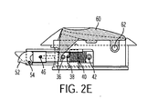
- Figure 2E shows the rocker actuated latch with cam assist as in Figures 1A to 1E .
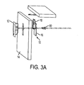
- Figure 3A to 3D shows the embodiment wherein the actuator is a generally rectangular paddle actuator 64 which is carried on paddle pin 66.
- the hammer 30 does not have a ramp and the bolt does not have an activating pin. Instead, the hammer presses down on the bolt spring when the paddle is rotated about pin 66, as shown in Figure 3F .
- the bolt spring may have a cap 68.
- the paddle actuator 76 is oval in shape.
- the oval paddle actuator 76 has a slot 70 which rides on pin 72 on the actuator housing. This allows the paddle actuator 76 together with hammer 30 to move as a whole.
- the oval paddle actuator 76 also has a linkage 74 connecting the underside of the oval paddle actuator 76 to the actuator housing. This arrangement affords smooth and easy operation of the oval paddle when the paddle is raised and pull out to work the bolt 20.
- the bolt mechanism assembly 10 and the actuator housing assembly 12 are screwed together.
- the back of the actuator housing assembly 12 has internally threads openings 78. Screws 80 are inserted in countersunk holes 58 in the backing 16 and into holes 80 to provide complementary means to enable attachment and detachment.
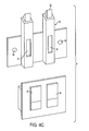
- the closure latching assembly may also contain dual bolt mechanism assemblies assembly and an actuator housing assembly having side-by-side paddles, as shown in Figures 4A and 4C .
- the construction and operation of the bolt is essentially the same as is discussed above in connection with the embodiment of Figures 3A to 3F .
- closure latching system of Figures 1A to 1F can also be modified to operate a pair of spaced apart side latches 82, providing three point latching. This is accomplished by the having two side openings 84 in the bolt housing 18. Linkages 86 connect the bolt with the two side or spaced apart latches 82 such that movement of the bolt to open the center latch also functions to open the two side latches.
- the bolt mechanism assembly is preferably comprised of a housing 18 in the form of extruded T shaped extrusion carrying a bolt assembly including the bolt 20 and the spring 40 and is self contained.
- An upper bolt pin 46 intersects and press is fitted to the bolt assembly and travels along slots 48 in the housing 18.
- spring retaining pin 42 keeps the spring 40 captured within the bolt housing 18.
- the housing 18 has a square hole along its length to allow the bolt 20 to slide.
- the flat part of the T on the housing 18 forms plate 16 which is secured with screws to the actuator housing assembly 12 when installed on to the panel 14 through two counter sunk holes 58 that line up with the actuator housing threaded holes 76.
- a window or access opening 34 is provided in the wall of the housing 18 opposite the backing plate 16 to allow the hammer 30 to advance.
- the sliding bolt 20 is a square rod with a determined length and a 45 degree beveled edge.
- the bolt end comprises space to accommodate the pivotally mounted cam 52 that assists the initial pushing down of the bolt 20 when the panel 14 is closed against the striker 24.
- the cam 52 rotates in the fork 50 about cam pin 54.
- the cam 52 is preferably made of plastic to reduce noise during opening and closing.
- the bolt assembly is accomplished by inserting the spring, then the bolt assembly, installing the upper bolt pin 46 through the slot 48 just below the cam assist device and installing a cam retaining pin 54 to support the cam 52 assist device.
- the shape and length of the extrusion and bolt may vary to accommodate the esthetic shape or function of the particular latch actuating housing assembly or to accommodate the placement of the latch with respect to the striker.
- the actuator housing assembly is the part of the closure latching system that can vary in shape, esthetic preference and in the function for actuation.
- the bolt mechanism assembly is designed to be used with any actuator housing assembly style, esthetic look or design with few changes to accommodate attachments or length of bolt.
- the same mechanism can be used with many latch assemblies, differing only in appearance.
- the actuator housing assembly provides for many styles, for example; a push button latch application, a rocker latch application, a paddle or lever style application, but is not limited to these applications.
- the actuator housing is the portion of the latch that is visible to its operator and can be designed in many forms and functions for each of the style applications.
- the esthetic designs for the actuator housing are many, and include finger grips formed therein or attached thereto having shapes that are oval, square, rounded, oblong, geometrical in shape or that are formed with a non-conforming shape and/or surfaces.
- the objective of the closure latching system is to allow flexibility of design, ease of assembly and simplification of manufacturing.
- This present invention provides the freedom to design a line of latches that is variable in appearance, function and style. Having the system designed in two parts as mentioned above allows an economic way to manufacture many styles having a variety of appearances.
- the invention provides for the changing of actuator housing assembly to accomplish any desired change in appearance.
- the underside of the paddle is preferably provided with rubber or silicone bumpers to eliminate noise from vibrations common in transportation vehicles.
- the rotatable sleeve 38 When the bolt activating pin 36 is tightly received in a lateral hole in bolt 20, the rotatable sleeve 38 is provided so that it can rotate around the pin under hammer pressure.
- the bolt activating pin 36 can be slightly smaller in diameter than the lateral hole in the bolt so that the pin itself can rotate under hammer pressure, in which case the sleeve is not necessary.
- This invention can be used for securing of doors, drawers, bins or it can be used for as a restraint system for the marine, household, transportation or the aerospace industries.
- the latches of this invention can have two, three or more point latching applied to the bolt mechanism while allowing the manufacturer the flexibility of providing esthetically different appearance to the portion of the latch that is visible to the user.
- the backing plate 16 is preferably an integral part of the bolt mechanism assembly which eliminates the need for and cost to the customer of providing a backing plate.
Abstract


Description
- Bolt latches are commonly used to secure doors, bins, overhead lockers, etc., particularly in the interior of aircraft and marine vessels to allow opening for access and closing to lock or secure.
- For decades the aerospace and marine industries has offered latches of similar appearance and operation leaving the users in the industry with few choices and a lack of variety in esthetic appearance from which to choose latches for aircraft, yachts or the like.
- One reason there is very little variety in the appearance and styles of latches is the cost of manufacture and tooling. Casting is the way to make latches affordable and to cover the complexity of a latch which is manufactured as a unitary assembly. An example of such a unitary assembly is described in Andrews United States Patent No.
3,243,336 . However, manufacturing costs for a unitary latch assembly are very costly due to the complexity of the parts. The unitary latch assembly requires a more expensive mold for casting and is complex to manufacture by machining. - Briefly, the present invention comprises a two assembly part latch system comprising the "actuator housing assembly" and the "bolt mechanism assembly", which provides the application of several actuating functions for the actuator housing assembly while maintaining the same bolt mechanism assembly for latching. The "actuator housing assembly" is the visible portion of the latch that is used to actuate the bolt mechanism assembly. The latch forming part of the bolt mechanism assembly can be activated by means of a paddle acting as a lever over a pivoting axis, a push button acting in a linear action, or a rocker push button, acting in arc motion by means of pushing over a pivot axis.
- It is a major feature of this invention that the two assemblies can be attached and detached from each other. In this way the one assembly can be changed, leaving the other in place. This permits, for example, the switching out of the actuator housing assembly to provide different activation means, viz., paddle, push button, rocker, as desired. This is significant since normally the activation means is visible within an aircraft or marine vessel and provides aesthetic effects as well as function. Thus, this invention makes it easier to accommodate a desired aesthetic choice of color or artwork.
- In one aspect, the invention comprises a bolt mechanism assembly comprising:
- means for mounting on a complementary surface of a panel,
- a bolt mechanism assembly housing carried by said means for mounting,
- a sliding bolt assembly carried by said bolt mechanism assembly housing including a bolt, one end of which has means adapted to engage and latch to a striker,
- a spring in said housing for keeping said end of the bolt extending out of the bolt mechanism assembly housing to latch to the striker,
- said bolt mechanism assembly housing including access means for a hammer adapted to compress said spring and withdraw said end of said bolt from latching to said striker,
- said backing plate having means adapted to enable attachment to and detachment from an actuator housing assembly having complementary means adapted to enable attachment and detachment.
- The invention further comprises a bolt mechanism assembly comprising:
- a backing plate adapted to be mounted on a complementary surface of a panel,
- a bolt mechanism assembly housing attached to said backing plate,
- a sliding bolt assembly carried by said bolt mechanism assembly housing including a bolt one end of which has means adapted to engage and latch to a striker, said bolt having a laterally extending projection,
- a spring in said housing for keeping said end of the bolt extending out of the bolt mechanism assembly housing to latch to the striker
- said bolt mechanism assembly housing including access means for a hammer adapted to compress said spring and withdraw said end of said bolt from latching to said striker
- said means for mounting adapted to enable attachment to and detachment from an actuator housing assembly having complementary means adapted to enable attachment and detachment.
- In another aspect, the invention comprises an actuator housing assembly comprising:
- an actuator housing having an opening therein,
- a movable actuator member, received in said opening, said actuator member having a front surface and a rear surface and being digitally movable in said opening,
- a hammer extending from said rear surface of said movable actuator member
- said actuator housing assembly having means adapted to enable the attachment to and detachment from a bolt mechanism assembly having complementary means adapted to enable attachment and detachment.
- In still another aspect, the invention comprises an easily modified closure latching system comprising the combination of a bolt mechanism assembly and an actuator housing assembly,
- said bolt mechanism assembly comprising
- a backing plate adapted to be mounted on a complementary surface of a panel,
- a bolt mechanism assembly housing attached to said backing plate,
- a sliding bolt assembly carried by said bolt mechanism assembly housing, said sliding bolt assembly including a bolt one end of which has means adapted to engage and latch to a striker,
- a spring in said housing for keeping said end of the bolt extending out of the housing to latch to the striker,
- said bolt mechanism assembly housing including access means for a hammer adapted to compress said spring and withdraw said end of the bolt from latching to said striker; and
- attachably and detachably connected to said bolt mechanism assembly in operative relationship,
- said actuator housing assembly comprising
- an actuator housing having an opening therein,
- a movable actuator member received in said opening, said actuator member having a front surface and a rear surface and being digitally movable in said opening,
- a hammer extending from said rear surface of said movable actuator member and adapted to move in said opening and to compress said spring upon movement of said actuator member and withdraw said bolt from latching to said striker.
- In one embodiment, the invention comprises an easily modified closure latching system comprising the combination of a bolt mechanism assembly and an actuator housing assembly,
- said bolt mechanism assembly comprising
- a backing plate adapted to be mounted on a complementary surface of a panel
- a pair of bolt mechanism assembly housings attached to said backing plate,
- a pair of side-by-side sliding bolt assemblies carried by said bolt assembly housing, each said sliding bolt assemblies including a bolt one end of each of which has means adapted to engage and latch to a striker,
- springs in said housing for keeping end of each the bolts extending out of the housing to latch to a striker,
- each said bolt mechanism assembly housing including access means for a hammer adapted to compress said spring and withdraw said end of the bolt from latching to said striker; and
- attachably and detachably connected to said bolt mechanism assembly in operative relationship,
- said actuator housing assembly comprising
- an actuator housing having a pair of openings therein,
- movable actuators member received in each said openings, each said actuator member having a front surface and a rear surface and being digitally movable in said opening,
- a hammer extending at an essentially right angle from said rear surface of each of said movable actuator members and adapted to move in said opening and to compress said spring upon movement of said actuator members and withdraw said bolts from latching to said strikers.
- In one preferred embodiment, the invention comprises an easily modified closure latching system comprising the combination of a bolt mechanism assembly and an actuator housing assembly,
- said bolt mechanism assembly comprising
- a backing plate adapted to be mounted on a complementary surface of a panel
- a bolt mechanism assembly housing attached to said backing plate,
- a sliding bolt assembly carried by said bolt mechanism assembly housing said sliding bolt assembly including a bolt one end of which has means adapted to engage and latch to a striker, said bolt having a laterally extending projection,
- a spring in said housing for keeping said end of the bolt out of the housing to latch to the striker
- said bolt mechanism assembly housing including passage access for a hammer adapted to compress said spring and withdraw said end of the bolt from latching to said striker; and
- attachably and detachably connected to said bolt mechanism assembly in cooperative relationship,
- said actuator housing assembly comprising
- an actuator housing having an opening therein,
- a movable push button actuator member received in said opening, said actuator member having a front surface and a rear surface and being digitally movable in said opening,
- a hammer extending at an essentially right angle from said rear surface of said movable push button actuator member and adapted to move in said opening and to compress_said spring by contact with said laterally extending projection upon inward movement of said push button actuator member and withdraw said bolt from latching to said striker.
- In another embodiment, the invention comprises an easily modified closure latching system comprising the combination of a bolt mechanism assembly and an actuator housing assembly,
- said bolt mechanism assembly comprising
- a backing plate adapted to be mounted on a complementary surface of a panel
- a bolt mechanism assembly housing attached to said backing plate,
- a sliding bolt assembly carried by said bolt mechanism assembly housing, said sliding bolt assembly including a bolt one end of which has means adapted to engage and latch to a striker, said bolt having a laterally extending projection,
- a spring in said housing for keeping said end of the bolt out of the housing to latch to the striker
- said bolt mechanism assembly housing including access means for a hammer adapted to compress said spring and withdraw said end of the bolt from latching to said striker; and
- attachably and detachably connected to said bolt mechanism assembly in operative relationship,
- said actuator housing assembly comprising
- an actuator housing having an opening therein,
- a movable rocker actuator member pivotally received in said opening and pivotally attached to said actuator housing, said actuator member having a front surface and a rear surface and being digitally movable in said opening,
- a hammer extending at an essentially right angle from said rear surface of said movable rocker actuator member and adapted to move in said opening and to compress said spring by contact with said laterally extending projection upon pivotal inward movement of said rocker actuator member and withdraw said bolt from latching to said striker.
- In still another embodiment, the invention comprises an easily modified closure latching system comprising the combination of a bolt mechanism assembly and an actuator housing assembly,
- said bolt mechanism assembly comprising
- a backing plate adapted to be mounted on a complementary surface of a panel
- a bolt mechanism assembly housing attached to said backing plate,
- a sliding bolt assembly carried by said bolt mechanism assembly housing, said sliding bolt assembly including a bolt one end of which has means adapted to engage and latch to a striker;
- a spring in said housing for keeping said end of the bolt out of the housing to latch to the striker
- said bolt mechanism assembly housing including access means for a hammer adapted to compress said spring and withdraw said end of the bolt from latching to said striker; and
- attachably and detachably connected to said bolt mechanism assembly in operative relationship,
- said actuator housing assembly comprising
- an actuator housing having an opening therein,
- a movable paddle actuator member pivotally received in said opening, said actuator member having a front surface and a rear surface and being digitally movable in said opening,
- a hammer extending at an essentially right angle from said rear surface of said movable paddle actuator member and adapted to move in said opening and to compress said spring upon pivotal movement of said paddle actuator member outwardly from said actuator housing and withdraw said bolt from latching to said striker.
- In another preferred embodiment, the invention comprises an easily modified three point closure latching system for engagement with three spaced apart strikers comprising the combination of a bolt mechanism assembly and an actuator housing assembly,
- said bolt mechanism assembly comprising
- a backing plate adapted to be mounted on a complementary surface of a panel
- a bolt mechanism assembly housing attached to said backing plate,
- a sliding bolt assembly carried by said bolt mechanism assembly housing, said sliding bolt assembly including a bolt one end of which has means adapted to engage and latch to a striker,
- a spring in said housing for keeping said end of the bolt out of the housing to latch to the striker
- said bolt assembly housing including access means for a hammer adapted to compress said spring and withdraw said end of the bolt from latching to said striker
- attachably and detachably connected to said bolt mechanism assembly in operative relationship,
- said actuator housing assembly comprising
- an actuator housing having an opening therein,
- a movable actuator member received in said opening, said actuator member having a front surface and a rear surface and being digitally movable in said opening,
- a hammer extending at an essentially right angle from said rear surface of said movable actuator member and adapted to move in said opening and to compress said spring upon movement of said actuator member and withdraw said bolt from latching to said striker,
- lateral openings in a said bolt assembly housing,
- two laterally spaced apart latch means; and
- linkage means through said lateral openings connecting said bolt to each of said spaced apart latch means,
- whereby when said spring is compressed, said bolt withdraws the end thereof from latching to said striker and simultaneously unlatches said two laterally spaced apart latch means.
- There are two main component assemblies forming the closure latching system of this invention, the bolt mechanism assembly (mechanism) and the actuator housing assembly. The actuator housing assembly includes a pivoting lever paddle or a pivoting elongated rocker button, or a push button. This assembly of the latch can be designed to take many forms and styles to accommodate different esthetic designs. The actuator housing assembly has a housing, carrying the paddle, rocker or push button, all equipped with a hammer projecting from the rear surface that is adapted to interface with the mechanism to pull down the latching bolt. In cases where the paddle or rocker lever applications are used, a pivot pin is used to activate the bolt with the hammer. The latch paddle when pulled over center of the pivot pin forces the bolt to move down, thus opening the latch assembly. In case the latch is a push button type, the hammer connected to the button has a hammer bevel or ramp which engages the bolt to move it down when the button is pushed.
- The actuator housing assembly preferably is equipped with two threaded helicoils on the back side of the actuator housing assembly to secure to the closure latching system upon installation of the system to the door or drawer panel. The mechanism is designed to be similar in every instance of use (except for derivatives that require length adjustment to accommodate the users requirements). The mechanism is comprised of an extruded aluminum housing that serves a guide for the sliding of a steel (nylon in some marine/other applications) bolt up and down, a spring is used to return the bolt to the up position and is retained in place by the use of the retaining pin. The bolt is designed with a cavity or access opening to accommodate the action of the hammer that is part of the push button or rocker. The bolt mechanism assembly extrusion has a flange having two counter sunk holes therein which are used to screw the bolt mechanism assembly to the latch actuating housing during installation to the cabinet door or panel.
- The closure latching system can be machined and/or cast to make latches affordable. Casting or machining is more affordable than the conventional one piece latch which requires complex casting techniques.
- In the drawings:
-
Figure 1A is an exploded perspective view of the push button actuated embodiment of the latch of this invention showing how the device is mounted on a panel and the bolt engage striker. -
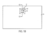
Figure 1B is a front plan view showing the push button actuated embodiment mounted on a panel. -
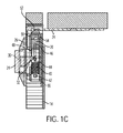
Figure 1C is a sectional view generally taken along theline 1C-1C inFigure 1B together with the striker, and showing the latch in the closed position. -
Figure 1D is also a sectional view differing fromFigure 1C in that the latch has been opened. -
Figure 1E is an exploded view of the bolt mechanism assembly with backing plate prior to mounting on a panel. -
Figure 2A is similar toFigure 1A and shows the rocker actuated embodiment of the latch of this invention. -
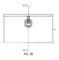
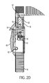
Figure 2B is a front plan view showing the rocker actuated embodiment mounted on a panel. -
Figure 2C is a sectional view generally taken along theline 2C-2C inFigure 2B together with the striker and showing the latch in the closed position. -
Figure 2D is also a sectional view taken from the opposite side and differing fromFigure 2C in that the latch has been opened. -
Figure 2E is a sectional view of an alternative embodiment of the rocker actuated latch. -
Figure 3A is similar toFigure 1A and shows a generally rectangular paddle actuated embodiment of this invention. -
Figure 3B is a front plan view showing the rectangular paddle actuated embodiment mounted on a panel. -
Figure 3C shows the bolt mechanism assembly and the actuator housing assembly of the embodiment ofFigures 3A and3B , ready for attachment to a panel. -
Figure 3D shows top, front and side views of the assemblies ofFigure 3C after being screwed together. -
Figure 3E is a sectional view taken along theline 3E-3E inFigure 3B together with the striker showing the latch in the closed position, with the further proviso that the bolt is cam assembled. -
Figure 3F is also a sectional view differing fromFigure 3E in that the latch has been opened. -
Figure 3G is a sectional view of an alternate embodiment of the paddle actuated latch wherein the actuator is oval in shape and the bolt is solid. -
Figure 4A is a front view of yet another embodiment of this invention having two bolts and two actuators or paddles, and otherwise similar to the embodiment ofFigures 3A to 3F , showing the closure latching system as disposed on a door panel. -
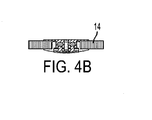
Figure 4B is a sectional view taken along theline 4B-4B inFigure 4A . -
Figure 4C shows the embodiment ofFigures 4A and4B in perspective views. -
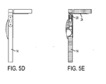
Figure 5A is a perspective view showing one embodiment of the closure latching system of this invention connected to two additional spaced-apart latches, each with a striker, and adapted when installed to provide three point latching actuated by a single actuator. -
Figure 5B is a top view of the parts shown inFigure 5A as installed on a flat panel. -
Figure 5C is a rear plan view of the installation shown inFigure 5B . -
Figure 5D is a side plan view of the structure shown inFigure 5C . -
Figure 5E is a sectional view taken along theline 5E-5E inFigure 5C . -
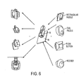
Figure 6 shows many of the different configurations of the invention, all based on the same bolt mechanism assembly while having different actuator housing assemblies. Each of the actuator housing assemblies shown can be attached to the same bolt mechanism assembly. -
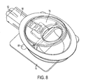
Figure 7 is an enlarged perspective view of the embodiment ofFigure 3G prior to being screwed together and mounted on a panel with the oval actuator in the raised or open position. -
Figure 8 is the same device asFigure 7 with the viewing angle shifted approximately 90° to the right. -
- bolt mechanism assembly
- 10
- actuator housing assembly
- 12
- panel
- 14
- bolt mechanism backing plate
- 16
- bolt housing
- 18
- bolt
- 20
- bolt end
- 22
- striker
- 24
- push button actuator
- 26
- push button actuator housing
- 28
- hammer
- 30
- ramp on hammer
- 32
- hammer access opening in bolt housing
- 34
- bolt actuating pin
- 36
- rotatable sleeve on bolt actuating pin
- 38
- bolt spring
- 40
- spring retaining pin
- 42
- lower bolt pin
- 44
- upper bolt pin
- 46
- slots in bolt housing
- 48
- fork
- 50
- cam
- 52
- cam pin
- 54
- cam support surface
- 56
- countersunk holes in backing plate
- 58
- rocker actuator
- 60
- rocker pivot pin
- 62
- paddle actuator
- 64
- paddle pin
- 66
- spring cap
- 68
- oval paddle actuator slot
- 70
- oval paddle slot pin
- 72
- oval paddle actuator linkage
- 74
- oval paddle actuator
- 76
- threaded openings in actuator
- 78
- screws
- 80
- side latches
- 82
- side openings in bolt housing
- 84
- linkages connecting to side latches
- 86
- Turning to the drawings in more detail, with particular reference to the push button actuated embodiment of
Figures 1A to 1E , thebolt mechanism assembly 10 andactuator housing assembly 12 are mounted onpanel 14. Thebolt mechanism 10 has abacking plate 16. Thebolt mechanism 10 also includes thebolt housing 18 in which is receivedbolt 20 withbolt end 22. Thebolt 20 reciprocates within thebolt housing 18. Thebolt end 22 is adapted to engage and latch tostriker 24 which is carried on any standard storage locker frame, drawer frame and the like. - The
push button actuator 26 is mounted in anactuator housing 28. The actuator has on its inner side a generally projectinghammer 30. Thehammer 30 has aramp 32 on its underside which serves to actuate thebolt 20, as explained below. - The
bolt housing 18 has ahammer access opening 34. Upon assembly of thebolt mechanism assembly 10 and theactuator assembly 12, thehammer 30 projects through the access opening 34 to engage thebolt activating pin 36. Thepin 36 is preferably fixed into thebolt 20 and carried around it, a rotatable sleeve orbushing 38. - The
ramp 32 on the hammer is adapted to engage therotatable sleeve 38 when theactuator 26 is pushed in. The rotatability of thesleeve 38 on thepin 36 provide for smooth action when opening the latch. - The
bolt 20 rides on acompressible coil spring 40. Thespring 40 is received within thebolt housing 18 in a fairly snug fashion. Thecoil spring 40 is held within thebolt housing 18 byspring retaining pin 42. The spring is normally not fastened to thepin 42, the pin serving as a stop or rest to keep the spring within the bolt housing. - The
lower bolt pin 44 is carried in side openings or through a hole at the lower extremity ofbolt 20.Pin 44 is adapted to engage the upper surface ofbolt coil spring 40 when to bolt is activated, that is, when the bolt moves down, thepin 44 presses down on the upper surface of thebolt spring 40, causing it to compress. - The
upper bolt pin 46 runs laterally throughbolt 20 with the ends ofpin 46 being slidably received in theslots 48 in thebolt housing 18 so that thepin 46 moves up and down in theslots 48 and thebolt 20 moves up and down in thebolt housing 18. Theend 22 of thebolt 20 which engages thestriker 24 in one preferred embodiment has aforklike configuration 50 having acam 52 received therein. Thecam 52 is pivotally carried bycam pin 54 which is carried by thebolt housing 18. As can be seen inFigure 1C , in the closed position, the free end ofcam 52 rests on thecam surface 56 of the bolt. As the bolt moves down, this support is withdrawn and thecam 52 pivots oncam pin 54 to withdrawn the cam from engagement withstriker 24, as shown inFigure 1D . - The bolt
mechanism backing plate 16 has countersunk holes therein whereby thebolt mechanism assembly 10 can be joined to theactuator housing assembly 12 and the two joined topanel 14. - In operation, upon assembly with the
bolt end 22 engaging thestriker 24, when thepush button actuator 26 is digitally pushed in, theramp 32 onhammer 30 engages therotatable sleeve 38 onbolt actuating pin 36, causing thebolt 20 to move down as theramp 32 advances onsleeve 38, compressing thebolt spring 40 which simultaneously allows thecam 52 to pivot aboutpin 54 and clear the striker. When the pressure on actuator is released, the bias of thespring 40 causes the various elements to return to the position shown inFigure 1C . - Turning to 2A to 2D, here the push button actuator is replaced by
rocker actuator 60 which is carried in the actuator housing byrocker pin 62 about which the rocker pivots. In this embodiment, theend 22 of thebolt 20 is solid square rod rather then being cam assisted. -
Figure 2E shows the rocker actuated latch with cam assist as inFigures 1A to 1E . -
Figure 3A to 3D shows the embodiment wherein the actuator is a generallyrectangular paddle actuator 64 which is carried onpaddle pin 66. In this embodiment, thehammer 30 does not have a ramp and the bolt does not have an activating pin. Instead, the hammer presses down on the bolt spring when the paddle is rotated aboutpin 66, as shown inFigure 3F . If desired, the bolt spring may have acap 68. - In the embodiment of
Figures 3E and3F , there is the cam assist. - In the alternate embodiment of
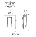
Figure 3G , thepaddle actuator 76 is oval in shape. Theoval paddle actuator 76 has a slot 70 which rides onpin 72 on the actuator housing. This allows thepaddle actuator 76 together withhammer 30 to move as a whole. Theoval paddle actuator 76 also has alinkage 74 connecting the underside of theoval paddle actuator 76 to the actuator housing. This arrangement affords smooth and easy operation of the oval paddle when the paddle is raised and pull out to work thebolt 20. - As can be seen in
Figure 3C , thebolt mechanism assembly 10 and theactuator housing assembly 12 are screwed together. The back of theactuator housing assembly 12 has internallythreads openings 78.Screws 80 are inserted in countersunkholes 58 in thebacking 16 and intoholes 80 to provide complementary means to enable attachment and detachment. - The closure latching assembly may also contain dual bolt mechanism assemblies assembly and an actuator housing assembly having side-by-side paddles, as shown in
Figures 4A and4C . The construction and operation of the bolt is essentially the same as is discussed above in connection with the embodiment ofFigures 3A to 3F . - Turning to
Figures 5A to 5E , the closure latching system ofFigures 1A to 1F can also be modified to operate a pair of spaced apart side latches 82, providing three point latching. This is accomplished by the having twoside openings 84 in thebolt housing 18.Linkages 86 connect the bolt with the two side or spaced apart latches 82 such that movement of the bolt to open the center latch also functions to open the two side latches. - The bolt mechanism assembly is preferably comprised of a
housing 18 in the form of extruded T shaped extrusion carrying a bolt assembly including thebolt 20 and thespring 40 and is self contained. Anupper bolt pin 46 intersects and press is fitted to the bolt assembly and travels alongslots 48 in thehousing 18. At the bottom of thehousing 18spring retaining pin 42 keeps thespring 40 captured within thebolt housing 18. - The
housing 18 has a square hole along its length to allow thebolt 20 to slide. The flat part of the T on thehousing 18forms plate 16 which is secured with screws to theactuator housing assembly 12 when installed on to thepanel 14 through two counter sunkholes 58 that line up with the actuator housing threaded holes 76. A window or access opening 34 is provided in the wall of thehousing 18 opposite thebacking plate 16 to allow thehammer 30 to advance. - The sliding
bolt 20 is a square rod with a determined length and a 45 degree beveled edge. In the cam assist embodiments, the bolt end comprises space to accommodate the pivotally mountedcam 52 that assists the initial pushing down of thebolt 20 when thepanel 14 is closed against thestriker 24. Thecam 52 rotates in thefork 50 aboutcam pin 54. Thecam 52 is preferably made of plastic to reduce noise during opening and closing. - The bolt assembly is accomplished by inserting the spring, then the bolt assembly, installing the
upper bolt pin 46 through theslot 48 just below the cam assist device and installing acam retaining pin 54 to support thecam 52 assist device. - The shape and length of the extrusion and bolt may vary to accommodate the esthetic shape or function of the particular latch actuating housing assembly or to accommodate the placement of the latch with respect to the striker.
- The actuator housing assembly is the part of the closure latching system that can vary in shape, esthetic preference and in the function for actuation.
- The bolt mechanism assembly is designed to be used with any actuator housing assembly style, esthetic look or design with few changes to accommodate attachments or length of bolt. The same mechanism can be used with many latch assemblies, differing only in appearance. The actuator housing assembly provides for many styles, for example; a push button latch application, a rocker latch application, a paddle or lever style application, but is not limited to these applications. The actuator housing is the portion of the latch that is visible to its operator and can be designed in many forms and functions for each of the style applications. The esthetic designs for the actuator housing are many, and include finger grips formed therein or attached thereto having shapes that are oval, square, rounded, oblong, geometrical in shape or that are formed with a non-conforming shape and/or surfaces.
- The objective of the closure latching system is to allow flexibility of design, ease of assembly and simplification of manufacturing. This present invention provides the freedom to design a line of latches that is variable in appearance, function and style. Having the system designed in two parts as mentioned above allows an economic way to manufacture many styles having a variety of appearances. The invention provides for the changing of actuator housing assembly to accomplish any desired change in appearance.
- In the paddle embodiment of the invention, the underside of the paddle is preferably provided with rubber or silicone bumpers to eliminate noise from vibrations common in transportation vehicles.
- When the
bolt activating pin 36 is tightly received in a lateral hole inbolt 20, therotatable sleeve 38 is provided so that it can rotate around the pin under hammer pressure. Alternatively, thebolt activating pin 36 can be slightly smaller in diameter than the lateral hole in the bolt so that the pin itself can rotate under hammer pressure, in which case the sleeve is not necessary. - This invention can be used for securing of doors, drawers, bins or it can be used for as a restraint system for the marine, household, transportation or the aerospace industries. The latches of this invention can have two, three or more point latching applied to the bolt mechanism while allowing the manufacturer the flexibility of providing esthetically different appearance to the portion of the latch that is visible to the user.
- In this invention, the
backing plate 16 is preferably an integral part of the bolt mechanism assembly which eliminates the need for and cost to the customer of providing a backing plate.
Claims (15)
- A bolt mechanism assembly comprising:means for mounting on a complementary surface of a panel,a bolt mechanism assembly housing carried by said means for mounting,a sliding bolt assembly carried by said bolt mechanism assembly housing including a bolt one end of which has means adapted to engage and latch to a striker,a spring in said housing for keeping said end of the bolt extending out of the bolt mechanism assembly housing to latch to the striker,said bolt mechanism assembly housing including access means for a hammer adapted to compress said spring and withdraw said end of said bolt from latching to said striker,said backing plate having means adapted to enable attachment to and detachment from an actuator housing assembly having complementary means adapted to enable attachment and detachment.
- A bolt mechanism assembly comprising:a backing plate adapted to be mounted on a complementary surface of a panel,a bolt mechanism assembly housing attached to said backing plate,a sliding bolt assembly carried by said bolt mechanism assembly housing including a bolt one end of which has means adapted to engage and latch to a striker, said bolt having a laterally extending projection,a spring in said housing for keeping said end of the bolt extending out of the bolt mechanism assembly housing to latch to the strikersaid bolt mechanism assembly housing including access means for a hammer adapted to compress said spring and withdraw said end of said bolt from latching to said strikersaid means for mounting adapted to enable attachment to and detachment from an actuator housing assembly having complementary means adapted to enable attachment and detachment.
- An actuator housing assembly comprising:an actuator housing having an opening therein,a movable actuator member, received in said opening, said actuator member having a front surface and a rear surface and being digitally movable in said opening,a hammer extending from said rear surface of said movable actuator membersaid actuator housing assembly having means adapted to enable the attachment to and detachment from a bolt mechanism assembly having complementary means adapted to enable attachment and detachment.
- An easily modified closure latching system comprising the combination of a bolt mechanism assembly and an actuator housing assembly,
said bolt mechanism assembly comprising
a backing plate adapted to be mounted on a complementary surface of a panel, a bolt mechanism assembly housing attached to said backing plate,
a sliding bolt assembly carried by said bolt mechanism assembly housing, said sliding bolt assembly including a bolt one end of which has means adapted to engage and latch to a striker,
a spring in said housing for keeping said end of the bolt extending out of the housing to latch to the striker,
said bolt mechanism assembly housing including access means for a hammer adapted to compress said spring and withdraw said end of the bolt from latching to said striker; and
attachably and detachably connected to said bolt mechanism assembly in operative relationship,
said actuator housing assembly comprising
an actuator housing having an opening therein,
a movable actuator member received in said opening, said actuator member having a front surface and a rear surface and being digitally movable in said opening,
a hammer extending from said rear surface of said movable actuator member and adapted to move in said opening and to compress said spring upon movement of said actuator member and withdraw said bolt from latching to said striker. - An easily modified closure latching system comprising the combination of a bolt mechanism assembly and an actuator housing assembly,
said bolt mechanism assembly comprising
a backing plate adapted to be mounted on a complementary surface of a panel a pair of bolt mechanism assembly housings attached to said backing plate,
a pair of side-by-side sliding bolt assemblies carried by said bolt assembly housing, each said sliding bolt assemblies including a bolt one end of each of which has means adapted to engage and latch to a striker,
springs in said housing for keeping end of each the bolts extending out of the housing to latch to a striker,
each said bolt mechanism assembly housing including access means for a hammer adapted to compress said spring and withdraw said end of the bolt from latching to said striker; and
attachably and detachably connected to said bolt mechanism assembly in operative relationship,
said actuator housing assembly comprising
an actuator housing having a pair of openings therein,
movable actuators member received in each said openings, each said actuator member having a front surface and a rear surface and being digitally movable in said opening,
a hammer extending at an essentially right angle from said rear surface of each of said movable actuator members and adapted to move in said opening and to compress said spring upon movement of said actuator members and withdraw said bolts from latching to said strikers. - An easily modified closure latching system comprising the combination of a bolt mechanism assembly and an actuator housing assembly,
said bolt mechanism assembly comprising
a backing plate adapted to be mounted on a complementary surface of a panel a bolt mechanism assembly housing attached to said backing plate,
a sliding bolt assembly carried by said bolt mechanism assembly housing said sliding bolt assembly including a bolt one end of which has means adapted to engage and latch to a striker, said bolt having a laterally extending projection,
a spring in said housing for keeping said end of the bolt out of the housing to latch to the striker
said bolt mechanism assembly housing including passage access for a hammer adapted to compress said spring and withdraw said end of the bolt from latching to said striker; and
attachably and detachably connected to said bolt mechanism assembly in cooperative relationship,
said actuator housing assembly comprising
an actuator housing having an opening therein,
a movable push button actuator member received in said opening, said actuator member having a front surface and a rear surface and being digitally movable in said opening,
a hammer extending at an essentially right angle from said rear surface of said movable push button actuator member and adapted to move in said opening and to compress said spring by contact with said laterally extending projection upon inward movement of said push button actuator member and withdraw said bolt from latching to said striker. - An easily modified closure latching system comprising the combination of a bolt mechanism assembly and an actuator housing assembly,
said bolt mechanism assembly comprising
a backing plate adapted to be mounted on a complementary surface of a panel
a bolt mechanism assembly housing attached to said backing plate,
a sliding bolt assembly carried by said bolt mechanism assembly housing, said sliding bolt assembly including a bolt one end of which has means adapted to engage and latch to a striker, said bolt having a laterally extending projection,
a spring in said housing for keeping said end of the bolt out of the housing to latch to the striker
said bolt mechanism assembly housing including access means for a hammer adapted to compress said spring and withdraw said end of the bolt from latching to said striker; and
attachably and detachably connected to said bolt mechanism assembly in operative relationship,
said actuator housing assembly comprising
an actuator housing having an opening therein,
a movable rocker actuator member pivotally received in said opening and pivotally attached to said actuator housing, said actuator member having a front surface and a rear surface and being digitally movable in said opening,
a hammer extending at an essentially right angle from said rear surface of said movable rocker actuator member and adapted to move in said opening and to compress said spring by contact with said laterally extending projection upon pivotal inward movement of said rocker actuator member and withdraw said bolt from latching to said striker. - An easily modified closure latching system comprising the combination of a bolt mechanism assembly and an actuator housing assembly,
said bolt mechanism assembly comprising
a backing plate adapted to be mounted on a complementary surface of a panel a bolt mechanism assembly housing attached to said backing plate,
a sliding bolt assembly carried by said bolt mechanism assembly housing, said sliding bolt assembly including a bolt one end of which has means adapted to engage and latch to a striker;
a spring in said housing for keeping said end of the bolt out of the housing to latch to the striker
said bolt mechanism assembly housing including access means for a hammer adapted to compress said spring and withdraw said end of the bolt from latching to said striker; and
attachably and detachably connected to said bolt mechanism assembly in operative relationship,
said actuator housing assembly comprising
an actuator housing having an opening therein,
a movable paddle actuator member pivotally received in said opening, said actuator member having a front surface and a rear surface and being digitally movable in said opening,
a hammer extending at an essentially right angle from said rear surface of said movable paddle actuator member and adapted to move in said opening and to compress said spring upon pivotal movement of said paddle actuator member outwardly from said actuator housing and withdraw said bolt from latching to said striker. - An easily modified three point closure latching system for engagement with three spaced apart strikers comprising the combination of a bolt mechanism assembly and an actuator housing assembly,
said bolt mechanism assembly comprising
a backing plate adapted to be mounted on a complementary surface of a panel a bolt mechanism assembly housing attached to said backing plate,
a sliding bolt assembly carried by said bolt mechanism assembly housing, said sliding bolt assembly including a bolt one end of which has means adapted to engage and latch to a striker,
a spring in said housing for keeping said end of the bolt out of the housing to latch to the striker
said bolt assembly housing including access means for a hammer adapted to compress said spring and withdraw said end of the bolt from latching to said striker
attachably and detachably connected to said bolt mechanism assembly in operative relationship,
said actuator housing assembly comprising
an actuator housing having an opening therein,
a movable actuator member received in said opening, said actuator member having a front surface and a rear surface and being digitally movable in said opening,
a hammer extending at an essentially right angle from said rear surface of said movable actuator member and adapted to move in said opening and to compress said spring upon movement of said actuator member and withdraw said bolt from latching to said striker,
lateral openings in a said bolt assembly housing,
two laterally spaced apart latch means; and
linkage means through said lateral openings connecting said bolt to each of said spaced apart latch means,
whereby when said spring is compressed, said bolt withdraws the end thereof from latching to said striker and simultaneously unlatches said two laterally spaced apart latch means. - The bolt mechanism assembly of claim 2 wherein:said bolt has a laterally extending projection snugly rotatably received in a hole in said bolt; and/orsaid bolt having a laterally extending projection is fixed in a lateral hole in said bolt and carries a sleeve rotatable about said pin.
- The bolt mechanism assembly of claim 1 wherein said means for mounting comprises a backing plate which extends beyond said housing.
- The bolt mechanism assembly of claim 1 wherein:said means to engage and latch to a striker includes a cam assist; and/orsaid means to engage and latch to a striker is the end of the bolt itself.
- The bolt mechanism assembly of claim 1 wherein said housing is integrally formed with said means for mounting.
- The actuator housing assembly of claim 3 wherein said actuator member is one or more of:a paddle;an oval paddle;a push button; ora rocker.
- The latching system of claim 4 wherein said bolt mechanism assembly and said actuator housing assembly has complementary means to enable attachment and detachment, wherein, optionally
said complementary means comprise a backing plate on said bolt mechanism assembly having screw holes therein and screw receiving openings on the actuator housing assembly and screws are received in said holes and are held by said openings.
Priority Applications (1)
| Application Number | Priority Date | Filing Date | Title |
|---|---|---|---|
| US13/325,633 US8789858B2 (en) | 2009-03-31 | 2011-12-14 | Two assembly parts latch system |
Applications Claiming Priority (1)
| Application Number | Priority Date | Filing Date | Title |
|---|---|---|---|
| US12/384,064 US8757675B2 (en) | 2009-03-31 | 2009-03-31 | Two assembly parts latch system |
Publications (3)
| Publication Number | Publication Date |
|---|---|
| EP2236712A2 true EP2236712A2 (en) | 2010-10-06 |
| EP2236712A3 EP2236712A3 (en) | 2015-04-22 |
| EP2236712B1 EP2236712B1 (en) | 2017-09-20 |
Family
ID=42315931
Family Applications (1)
| Application Number | Title | Priority Date | Filing Date |
|---|---|---|---|
| EP10250487.5A Active EP2236712B1 (en) | 2009-03-31 | 2010-03-16 | Combination of a panel and a latch sytem with two assembly parts |
Country Status (2)
| Country | Link |
|---|---|
| US (3) | US8757675B2 (en) |
| EP (1) | EP2236712B1 (en) |
Cited By (3)
| Publication number | Priority date | Publication date | Assignee | Title |
|---|---|---|---|---|
| WO2012155020A3 (en) * | 2011-05-12 | 2013-11-07 | Bombardier Inc. | Latch |
| WO2015131037A1 (en) * | 2014-02-27 | 2015-09-03 | Aai Corporation | Apparatus and method of attachment of a payload |
| GB2525898A (en) * | 2014-05-07 | 2015-11-11 | Widney Mfg Ltd | Handle assembly |
Families Citing this family (31)
| Publication number | Priority date | Publication date | Assignee | Title |
|---|---|---|---|---|
| US8757675B2 (en) * | 2009-03-31 | 2014-06-24 | The Young Engineers, Inc. | Two assembly parts latch system |
| US20110225890A1 (en) * | 2010-03-17 | 2011-09-22 | Mark Greenwood | Gate with foot-operated latching mechanism |
| EP2460962A1 (en) * | 2010-12-01 | 2012-06-06 | Orchidées Constructions S.A. | Locking device provided with at least one locking point for a sliding frame |
| CN102530437B (en) * | 2011-09-29 | 2014-04-30 | 上海鸿研物流技术有限公司 | Locking system suitable for large vessels |
| CN103163970B (en) * | 2011-12-08 | 2016-08-03 | 泰州市润扬电气有限公司 | Case of electronic device |
| DE102012001667A1 (en) * | 2012-01-28 | 2013-08-01 | Gm Global Technology Operations, Llc | Automotive cable actuator |
| US20130219793A1 (en) * | 2012-02-23 | 2013-08-29 | Master Lock Company Llc | Door locking assemblies and arrangements |
| US8887793B2 (en) | 2012-08-08 | 2014-11-18 | Milgard Manufacturing Incorporated | Screen attachment method for lineals |
| US20140167424A1 (en) * | 2012-12-19 | 2014-06-19 | The Young Engineers, Inc. | Magnetically Operated Latch |
| US9410348B1 (en) * | 2014-01-04 | 2016-08-09 | Carlson Pet Products, Inc. | Latch apparatus |
| US10161167B2 (en) * | 2014-04-16 | 2018-12-25 | GM Global Technlolgy Operations LLC | Lockable latching device |
| US9482751B2 (en) | 2014-10-13 | 2016-11-01 | Applied Concepts, Inc. | Collision detection system and method of operation |
| US9731827B2 (en) * | 2014-10-27 | 2017-08-15 | C&D Zodiac, Inc. | Overhead storage bin latch system |
| US20160168886A1 (en) * | 2014-12-11 | 2016-06-16 | Vision Industries Group, Inc. | Screwless Mounted Short-Throw Lock for Sliding Windows and Doors |
| CN204920551U (en) * | 2015-07-21 | 2015-12-30 | 安全保健有限公司 | A children safety lock mechanism for cupboard |
| EP3541703B1 (en) * | 2016-11-18 | 2022-08-24 | C&D Zodiac, Inc. | Overhead storage bin latch system |
| EP3369881B1 (en) * | 2017-03-02 | 2019-07-31 | Industrilås I Nässjö AB | Door handle arrangement with intermediate opening position |
| US10705105B2 (en) | 2017-07-21 | 2020-07-07 | Applied Concepts, Inc. | Absolute speed detector |
| US20200256091A1 (en) * | 2017-08-30 | 2020-08-13 | Bombardier Inc. | Latch assembly for aircraft monument |
| US10988963B2 (en) * | 2017-10-30 | 2021-04-27 | Bauer Products, Inc. | Door latch assembly |
| US10470561B2 (en) * | 2018-03-30 | 2019-11-12 | Lifetime Products, Inc. | Height adjustment mechanism |
| KR102525816B1 (en) * | 2018-05-02 | 2023-04-26 | 주식회사 위니아전자 | Device for locking home bar door in refrigerator |
| DE102018124159A1 (en) * | 2018-10-01 | 2020-04-02 | Hymer-Leichtmetallbau Gmbh & Co. Kg. | Flush operating handle for a locking device |
| EP3884130A4 (en) * | 2018-11-22 | 2022-07-27 | Huggan Co Pty Ltd | Latching mechanism |
| US11802428B2 (en) * | 2018-12-06 | 2023-10-31 | Overhead Door Corporation | Flush bolt assembly with bolt-contained spring |
| DE102019131209A1 (en) * | 2019-11-19 | 2021-05-20 | Dagmar Schöppl | Securing and unlocking devices and unlocking methods therefor |
| US11268296B2 (en) * | 2020-01-31 | 2022-03-08 | B/E Aerospace, Inc. | Toggle latch mechanism |
| US11732515B2 (en) * | 2020-03-06 | 2023-08-22 | Atieva, Inc. | Rotating flush vehicle door handle |
| CN111364832B (en) * | 2020-04-22 | 2021-03-23 | 武汉博畅通信设备有限责任公司 | Quick assembly disassembly handle |
| US20220299093A1 (en) * | 2021-03-16 | 2022-09-22 | Rockwell Automation Technologies, Inc. | Motion transformation |
| DE102021211644A1 (en) | 2021-10-14 | 2023-04-20 | B.PRO GmbH | Opening system for a car door |
Citations (1)
| Publication number | Priority date | Publication date | Assignee | Title |
|---|---|---|---|---|
| US3243336A (en) | 1964-11-30 | 1966-03-29 | John F Auge | Corsage assembly |
Family Cites Families (121)
| Publication number | Priority date | Publication date | Assignee | Title |
|---|---|---|---|---|
| US57423A (en) * | 1866-08-21 | Improvement in locks | ||
| US478556A (en) * | 1892-07-12 | Gate-latch | ||
| US107773A (en) * | 1870-09-27 | Improvement in sash-holders | ||
| US229995A (en) * | 1880-07-13 | freeman | ||
| US122061A (en) * | 1871-12-19 | Improvement in latches for gates | ||
| US233711A (en) * | 1880-10-26 | spencer | ||
| US529388A (en) * | 1894-11-20 | Thomas j | ||
| US161705A (en) | 1875-04-06 | Improvement in latches for doors | ||
| US545073A (en) | 1895-08-27 | Trolley | ||
| US708053A (en) | 1902-01-31 | 1902-09-02 | Anciens Etablissements Panhard | Apparatus for distributing the primary current for electric ignition by coils and igniters in explosive-engines. |
| US980630A (en) * | 1910-04-29 | 1911-01-03 | Edson Granger | Combined lock and latch. |
| US1111235A (en) * | 1914-01-02 | 1914-09-22 | Charles A Lindberg | Latch. |
| US1256992A (en) * | 1914-05-07 | 1918-02-19 | Linden E Edgar | Latch. |
| US1257998A (en) * | 1917-10-11 | 1918-03-05 | Archibald B Gruber | Push-button latch. |
| US1270288A (en) * | 1918-02-07 | 1918-06-25 | Archibald B Gruber | Push-button latch. |
| US1434373A (en) * | 1919-10-11 | 1922-11-07 | Crompton Edwin | Lock or latch |
| GB158780A (en) * | 1919-12-20 | 1921-02-17 | Harry Coombes | Improved locking device for spring latches |
| US1394681A (en) * | 1920-06-09 | 1921-10-25 | Duffa B Lauzon | Automobile-door latch |
| US1486998A (en) * | 1921-10-26 | 1924-03-18 | William R Wiley | Vehicle door lock |
| US1571453A (en) * | 1924-07-07 | 1926-02-02 | Maxon Curtis | Latch |
| US1746273A (en) | 1925-12-07 | 1930-02-11 | Graham Brothers | Latch mechanism |
| US1654256A (en) * | 1926-08-05 | 1927-12-27 | Automatic Lock And Closer Comp | Door fastener |
| US1828152A (en) * | 1928-10-31 | 1931-10-20 | William B Nonamaker | Push button latch |
| US1792154A (en) * | 1928-11-13 | 1931-02-10 | Cyrus E Miller | Doorlock |
| US1888238A (en) * | 1930-01-13 | 1932-11-22 | Bassick Co | Latch |
| US1965939A (en) * | 1931-11-09 | 1934-07-10 | Briggs & Stratton Corp | Compartment lock |
| US1964556A (en) * | 1932-09-02 | 1934-06-26 | Nat Mfg Co | Latch structure |
| US1989801A (en) * | 1933-06-26 | 1935-02-05 | Halinka George | Doorlatch |
| US1995338A (en) | 1934-04-17 | 1935-03-26 | William C Andrews | Door latching mechanism |
| US2055688A (en) * | 1935-03-22 | 1936-09-29 | Fred P Bock | Automobile door lock |
| US2036154A (en) * | 1935-05-02 | 1936-03-31 | Hickson F Littledale | Combined latch and lock structure |
| US2247937A (en) * | 1938-05-16 | 1941-07-01 | Nat Mfg Co | Latch structure |
| US2186666A (en) * | 1938-10-07 | 1940-01-09 | Cereda Jose Aurelio | Mechanism for operating locks, latches, and the like |
| US2201444A (en) * | 1938-10-12 | 1940-05-21 | Howard E Marsh | Automobile door latch operating means |
| US2383574A (en) * | 1943-11-17 | 1945-08-28 | Sargent & Co | Latch for hospital doors and the like |
| US2546703A (en) * | 1945-08-24 | 1951-03-27 | Eastern Malleable Iron Company | Automobile door lock |
| US2649322A (en) | 1946-05-20 | 1953-08-18 | Mack Grant | Flush door latching mechanism |
| US2573061A (en) * | 1947-01-22 | 1951-10-30 | Yale & Towne Mfg Co | Compartment lock |
| US2547108A (en) * | 1947-05-22 | 1951-04-03 | Carl E Anderson | Door latch |
| US2648561A (en) * | 1949-01-18 | 1953-08-11 | Robert W Landon | Push-button latch |
| US2780485A (en) * | 1954-05-14 | 1957-02-05 | Arnold A Dedoes | Reversable drawer and door pulls and latches |
| US2764440A (en) * | 1954-11-10 | 1956-09-25 | Soss Mfg Company | Door latch |
| US2893773A (en) * | 1955-07-25 | 1959-07-07 | American Art Metals Company | Latch and detent assembly |
| US2874986A (en) * | 1956-12-24 | 1959-02-24 | Clark Hartwell | Flush latch construction |
| US3055204A (en) * | 1960-01-05 | 1962-09-25 | Eastern Co | Latch mechanism |
| US3090643A (en) * | 1960-12-20 | 1963-05-21 | Ima Jean Barnes | Latch |
| US3385622A (en) * | 1966-05-16 | 1968-05-28 | Lorin D. Winger | Latch and lock mechanism |
| US3495862A (en) | 1968-03-08 | 1970-02-17 | Tridair Industries | Latch |
| US3659886A (en) | 1970-05-01 | 1972-05-02 | Sealth Aero Marine Co | Aircraft panels with precisely adjustable and easy action spring toggle latch |
| US3707862A (en) | 1971-02-19 | 1973-01-02 | Eastman Co | Key-controlled door lock |
| US3789550A (en) | 1972-06-12 | 1974-02-05 | Stahl Metal Prod Division | Corrosion-resistant, double-panel, lockable door |
| US3770306A (en) * | 1972-06-15 | 1973-11-06 | J Nystrom | Fire door lock assembly |
| US3743336A (en) | 1972-07-03 | 1973-07-03 | Sealth Aero Marine | Frictionless cabinet latch |
| DE7337299U (en) * | 1972-10-20 | 1976-05-20 | Neiman & Co Kg, 5600 Wuppertal | PUSH BUTTON OPERATED BOLT LOCK |
| US3782141A (en) | 1972-10-26 | 1974-01-01 | Hansen Mfg Co A L | Flush type door latch |
| US4116027A (en) | 1977-06-09 | 1978-09-26 | Theodore Bargman Company | Door lock |
| US4231597A (en) | 1978-05-05 | 1980-11-04 | The Eastern Company | Flush-type door lock |
| US4312205A (en) * | 1979-12-28 | 1982-01-26 | The Eastern Company | Paddle lock with rotatably-mounted handle disconnect member |
| US4335595A (en) | 1979-12-28 | 1982-06-22 | The Eastern Company | Paddle lock with handle disconnect |
| US4420954A (en) | 1981-12-14 | 1983-12-20 | Abex Corporation | Flush mountable door latch mechanism |
| JPS58153664U (en) * | 1982-04-08 | 1983-10-14 | タキゲン製造株式会社 | Door handle device |
| US4643469A (en) * | 1983-07-29 | 1987-02-17 | National Manufacturing Co. | Gate latch |
| JPS6080259U (en) * | 1983-11-05 | 1985-06-04 | タキゲン製造株式会社 | Door handle device |
| CA1235452A (en) * | 1984-04-18 | 1988-04-19 | Lee S. Weinerman | Cabinet lock with recessed handle |
| WO1988007616A1 (en) * | 1987-04-01 | 1988-10-06 | Willi Albrecht Althaus | Latch mechanism |
| USD303620S (en) | 1987-07-10 | 1989-09-26 | The Eastern Company | Flush mounted latch assembly |
| USD303621S (en) | 1987-07-10 | 1989-09-26 | The Eastern Company | Flush mounted latch assembly |
| US4818000A (en) * | 1987-12-09 | 1989-04-04 | The Stanley Works | Decorative surface bolt |
| GB8802495D0 (en) * | 1988-02-04 | 1988-03-02 | West Alloy Diecastings | Latch/lock for door |
| US4986576A (en) | 1988-12-27 | 1991-01-22 | The Hartwell Corporation | Locking door latch |
| US4951486A (en) * | 1989-11-07 | 1990-08-28 | Cleveland Hardware & Forging | Nested paddle lock assembly |
| JPH0438384A (en) * | 1990-05-31 | 1992-02-07 | Mita Ind Co Ltd | Locking device |
| US5072977A (en) * | 1991-07-29 | 1991-12-17 | Trans-Atlantic Company | Paddle latch device |
| US5201557A (en) * | 1991-09-24 | 1993-04-13 | Southco, Inc. | Slide fastener |
| JPH06257331A (en) * | 1993-03-04 | 1994-09-13 | Takigen Seizo Kk | Detachable type lock handle device |
| US5413391A (en) | 1993-07-12 | 1995-05-09 | Hartwell Corporation | Self-closing latch |
| US5657969A (en) | 1994-12-29 | 1997-08-19 | Illinois Tool Works Inc. | Snap-in push-push latch mechanism |
| KR960032597U (en) * | 1995-03-31 | 1996-10-24 | Tape recorder reservation recording switch | |
| JP3718823B2 (en) * | 1995-04-22 | 2005-11-24 | タキゲン製造株式会社 | Latch lock |
| US5823644A (en) * | 1995-06-14 | 1998-10-20 | Samsung Electronics Co., Ltd. | Personal computer with an easy assembly structure |
| US5823583A (en) | 1995-12-29 | 1998-10-20 | Nyx, Inc. | Latch mechanism for glove box door |
| US5689980A (en) * | 1996-01-29 | 1997-11-25 | The Eastern Company | Push button lock |
| US5927773A (en) * | 1997-02-19 | 1999-07-27 | Tri/Mark Corporation | Latch assembly for movable closure |
| US6231091B1 (en) * | 1998-06-09 | 2001-05-15 | Tri/Mark Corporation | Control mechanism for operating a latch |
| US6109669A (en) * | 1998-09-30 | 2000-08-29 | Southco, Inc. | Load floor slam-action paw latch |
| USD459973S1 (en) | 2000-10-11 | 2002-07-09 | The Eastern Company | Housing for latches and locks |
| US6460902B1 (en) * | 2000-10-27 | 2002-10-08 | Pompanette, Inc. | Slam latch and hatch assembly including a slam latch |
| WO2002044504A2 (en) * | 2000-12-03 | 2002-06-06 | Southco, Inc. | Load floor latch |
| US6722716B2 (en) | 2001-09-10 | 2004-04-20 | Owen Ralph Baser | Door handle assembly |
| US6877752B2 (en) | 2002-01-29 | 2005-04-12 | Anthony G. Edwards | Removable large wheel assembly for luggage with small wheels |
| US7175144B2 (en) * | 2002-06-18 | 2007-02-13 | Benq Corporation | Detachable base support |
| DE10392925T5 (en) * | 2002-07-01 | 2005-09-08 | Southco, Inc. | Two-point locking system |
| DE10343230A1 (en) | 2002-09-17 | 2004-09-23 | Southco, Inc. | Latch for e.g. securing panel in frame to keeper, has detent device pivoted to open position to move secondary pawl to open position away from frame to permit opening of closure member portion when main pawl is engaged with keeper or frame |
| US6708537B1 (en) | 2002-10-09 | 2004-03-23 | Tri/Mark Corporation | Door lock assembly with free floating paddle |
| US6854304B2 (en) * | 2002-10-22 | 2005-02-15 | S.P.E.P. Acquisition Corporation | Paddle lock |
| US6877782B2 (en) * | 2002-11-25 | 2005-04-12 | Southco, Inc. | Adjustable sliding bolt for a lock |
| US7111879B2 (en) | 2002-12-11 | 2006-09-26 | Tri/Mark Corporation | Latch assembly for movable closure element |
| US6938376B2 (en) * | 2003-03-11 | 2005-09-06 | Magdy Morssi Youssef | Door reinforcement system |
| USD502380S1 (en) * | 2003-05-15 | 2005-03-01 | The Eastern Company | Front portion of a paddle handle for operating latches |
| DE102004039930A1 (en) * | 2003-08-18 | 2005-05-19 | Southco, Inc. | loading area closure |
| KR20070029108A (en) * | 2003-09-11 | 2007-03-13 | 사우스코 인코포레이티드 | Load floor latch |
| DE20316663U1 (en) | 2003-10-29 | 2004-01-08 | Böllhoff GmbH | Lock with releasable locking |
| TWM249083U (en) * | 2003-12-26 | 2004-11-01 | Hon Hai Prec Ind Co Ltd | Mounting device for side panel of computer |
| JP4381831B2 (en) * | 2004-01-15 | 2009-12-09 | マツダ株式会社 | Door lock mechanism and door lock unit |
| DE202004005030U1 (en) | 2004-03-31 | 2004-06-03 | Emka Beschlagteile Gmbh & Co. Kg | Two-part cam lock |
| JP4446809B2 (en) * | 2004-06-18 | 2010-04-07 | 株式会社ニフコ | Lock mechanism |
| US7798540B1 (en) * | 2004-06-30 | 2010-09-21 | Southco, Inc. | Load-floor latch |
| CN100478541C (en) * | 2004-06-30 | 2009-04-15 | 索斯科公司 | Load-floor latch |
| US7261328B2 (en) * | 2004-10-18 | 2007-08-28 | Fastec Industrial Corp. | Push button latch release assembly |
| US7588211B2 (en) | 2004-11-03 | 2009-09-15 | Airbus Deutschland Gmbh | Baggage compartment in passenger transport system |
| US7201411B2 (en) * | 2004-11-18 | 2007-04-10 | Illinois Tool Works Inc | Push latch |
| US7267379B2 (en) | 2005-03-17 | 2007-09-11 | Architectural Builders Hardware Mfg., Inc. | Flush bolt |
| US20060255596A1 (en) * | 2005-05-10 | 2006-11-16 | Teng-Long Yong | Flush handle latch mechanism |
| CN2821662Y (en) * | 2005-07-02 | 2006-09-27 | 鸿富锦精密工业(深圳)有限公司 | Casing locking device |
| CN100530767C (en) * | 2005-07-09 | 2009-08-19 | 深圳富泰宏精密工业有限公司 | Cell cover dog-locking structure |
| US7393024B2 (en) * | 2005-11-14 | 2008-07-01 | Illinois Tool Works Inc. | Push latch |
| US7676990B2 (en) * | 2006-02-28 | 2010-03-16 | Truth Hardware Corporation | Positive action lock for sliding windows |
| TW200740169A (en) * | 2006-04-10 | 2007-10-16 | Benq Corp | A portable electronic device |
| US7603880B2 (en) * | 2007-12-10 | 2009-10-20 | Te-Ming Chen | Mortise lock |
| US8789858B2 (en) * | 2009-03-31 | 2014-07-29 | The Young Engineers, Inc. | Two assembly parts latch system |
| US8757675B2 (en) * | 2009-03-31 | 2014-06-24 | The Young Engineers, Inc. | Two assembly parts latch system |
-
2009
- 2009-03-31 US US12/384,064 patent/US8757675B2/en active Active
-
2010
- 2010-03-16 EP EP10250487.5A patent/EP2236712B1/en active Active
-
2011
- 2011-09-09 US US13/229,090 patent/US8534718B2/en active Active
-
2013
- 2013-08-14 US US13/967,192 patent/US8770634B2/en active Active
Patent Citations (1)
| Publication number | Priority date | Publication date | Assignee | Title |
|---|---|---|---|---|
| US3243336A (en) | 1964-11-30 | 1966-03-29 | John F Auge | Corsage assembly |
Cited By (5)
| Publication number | Priority date | Publication date | Assignee | Title |
|---|---|---|---|---|
| WO2012155020A3 (en) * | 2011-05-12 | 2013-11-07 | Bombardier Inc. | Latch |
| US10047549B2 (en) | 2011-05-12 | 2018-08-14 | Bombardier Inc. | Latch |
| WO2015131037A1 (en) * | 2014-02-27 | 2015-09-03 | Aai Corporation | Apparatus and method of attachment of a payload |
| US9308994B2 (en) | 2014-02-27 | 2016-04-12 | Aai Corporation | Apparatus and method of attachment of a payload |
| GB2525898A (en) * | 2014-05-07 | 2015-11-11 | Widney Mfg Ltd | Handle assembly |
Also Published As
| Publication number | Publication date |
|---|---|
| US20120013134A1 (en) | 2012-01-19 |
| EP2236712B1 (en) | 2017-09-20 |
| US8757675B2 (en) | 2014-06-24 |
| EP2236712A3 (en) | 2015-04-22 |
| US20130328327A1 (en) | 2013-12-12 |
| US20100244465A1 (en) | 2010-09-30 |
| US8534718B2 (en) | 2013-09-17 |
| US8770634B2 (en) | 2014-07-08 |
Similar Documents
| Publication | Publication Date | Title |
|---|---|---|
| US8770634B2 (en) | Two assembly parts latch system | |
| US8789858B2 (en) | Two assembly parts latch system | |
| EP1571029B1 (en) | Fuel door housing for automobiles | |
| US10004331B2 (en) | Drawer release | |
| EP2090468A1 (en) | Glove box assembly for a dashboard of a motor vehicle | |
| US20180223564A1 (en) | Rocker mechanism for locking door trim | |
| EP3112218B1 (en) | Roof box for vehicles | |
| KR20060069887A (en) | Exterior door handle with minimum surface intrusion | |
| KR101318564B1 (en) | Lock device | |
| US6554344B2 (en) | Fuel filler door catch for vehicles | |
| GB2536670A (en) | Rectractable handle arrangement | |
| US11591821B2 (en) | Modular closure device for different closure elements | |
| US4925222A (en) | Door latch actuating mechanism | |
| US20150135782A1 (en) | Push button lock | |
| CN111980508B (en) | Latch and catch assembly | |
| CA2778093C (en) | Privacy latch | |
| EP1932984A2 (en) | Lock for vehicle doors and hatches | |
| US8671623B2 (en) | Vehicle door manual lock assembly | |
| CN109072628A (en) | Improved full mortise handle and improved full mortice lock | |
| JP2019107265A (en) | Handle case in furniture | |
| KR200455331Y1 (en) | Grip Type Switch | |
| CN111101786A (en) | Door handle assembly | |
| US20230340804A1 (en) | Compression latch | |
| US20070028656A1 (en) | Lockable pull handle | |
| US11098507B2 (en) | Door handle assembly with retention feature |
Legal Events
| Date | Code | Title | Description |
|---|---|---|---|
| PUAI | Public reference made under article 153(3) epc to a published international application that has entered the european phase |
Free format text: ORIGINAL CODE: 0009012 |
|
| AK | Designated contracting states |
Kind code of ref document: A2 Designated state(s): AT BE BG CH CY CZ DE DK EE ES FI FR GB GR HR HU IE IS IT LI LT LU LV MC MK MT NL NO PL PT RO SE SI SK SM TR |
|
| AX | Request for extension of the european patent |
Extension state: AL BA ME RS |
|
| RAP1 | Party data changed (applicant data changed or rights of an application transferred) |
Owner name: LORET DE MOLA, MANUEL Owner name: THE YOUNG ENGINEERS, INC. |
|
| PUAL | Search report despatched |
Free format text: ORIGINAL CODE: 0009013 |
|
| AK | Designated contracting states |
Kind code of ref document: A3 Designated state(s): AT BE BG CH CY CZ DE DK EE ES FI FR GB GR HR HU IE IS IT LI LT LU LV MC MK MT NL NO PL PT RO SE SI SK SM TR |
|
| AX | Request for extension of the european patent |
Extension state: AL BA ME RS |
|
| RIC1 | Information provided on ipc code assigned before grant |
Ipc: E05C 1/12 20060101AFI20150313BHEP Ipc: E05B 63/14 20060101ALN20150313BHEP Ipc: E05C 9/00 20060101ALN20150313BHEP |
|
| 17P | Request for examination filed |
Effective date: 20151015 |
|
| RBV | Designated contracting states (corrected) |
Designated state(s): AT BE BG CH CY CZ DE DK EE ES FI FR GB GR HR HU IE IS IT LI LT LU LV MC MK MT NL NO PL PT RO SE SI SK SM TR |
|
| 17Q | First examination report despatched |
Effective date: 20160428 |
|
| STAA | Information on the status of an ep patent application or granted ep patent |
Free format text: STATUS: EXAMINATION IS IN PROGRESS |
|
| RIC1 | Information provided on ipc code assigned before grant |
Ipc: E05C 9/00 20060101ALN20170411BHEP Ipc: E05B 63/14 20060101ALN20170411BHEP Ipc: E05C 1/12 20060101AFI20170411BHEP |
|
| RIC1 | Information provided on ipc code assigned before grant |
Ipc: E05C 1/12 20060101AFI20170420BHEP Ipc: E05B 63/14 20060101ALN20170420BHEP Ipc: E05C 9/00 20060101ALN20170420BHEP |
|
| GRAP | Despatch of communication of intention to grant a patent |
Free format text: ORIGINAL CODE: EPIDOSNIGR1 |
|
| STAA | Information on the status of an ep patent application or granted ep patent |
Free format text: STATUS: GRANT OF PATENT IS INTENDED |
|
| INTG | Intention to grant announced |
Effective date: 20170606 |
|
| GRAS | Grant fee paid |
Free format text: ORIGINAL CODE: EPIDOSNIGR3 |
|
| GRAA | (expected) grant |
Free format text: ORIGINAL CODE: 0009210 |
|
| STAA | Information on the status of an ep patent application or granted ep patent |
Free format text: STATUS: THE PATENT HAS BEEN GRANTED |
|
| AK | Designated contracting states |
Kind code of ref document: B1 Designated state(s): AT BE BG CH CY CZ DE DK EE ES FI FR GB GR HR HU IE IS IT LI LT LU LV MC MK MT NL NO PL PT RO SE SI SK SM TR |
|
| REG | Reference to a national code |
Ref country code: GB Ref legal event code: FG4D |
|
| REG | Reference to a national code |
Ref country code: CH Ref legal event code: EP |
|
| REG | Reference to a national code |
Ref country code: AT Ref legal event code: REF Ref document number: 930253 Country of ref document: AT Kind code of ref document: T Effective date: 20171015 |
|
| REG | Reference to a national code |
Ref country code: IE Ref legal event code: FG4D |
|
| REG | Reference to a national code |
Ref country code: DE Ref legal event code: R096 Ref document number: 602010045337 Country of ref document: DE |
|
| REG | Reference to a national code |
Ref country code: NL Ref legal event code: MP Effective date: 20170920 |
|
| PG25 | Lapsed in a contracting state [announced via postgrant information from national office to epo] |
Ref country code: LT Free format text: LAPSE BECAUSE OF FAILURE TO SUBMIT A TRANSLATION OF THE DESCRIPTION OR TO PAY THE FEE WITHIN THE PRESCRIBED TIME-LIMIT Effective date: 20170920 Ref country code: FI Free format text: LAPSE BECAUSE OF FAILURE TO SUBMIT A TRANSLATION OF THE DESCRIPTION OR TO PAY THE FEE WITHIN THE PRESCRIBED TIME-LIMIT Effective date: 20170920 Ref country code: SE Free format text: LAPSE BECAUSE OF FAILURE TO SUBMIT A TRANSLATION OF THE DESCRIPTION OR TO PAY THE FEE WITHIN THE PRESCRIBED TIME-LIMIT Effective date: 20170920 Ref country code: NO Free format text: LAPSE BECAUSE OF FAILURE TO SUBMIT A TRANSLATION OF THE DESCRIPTION OR TO PAY THE FEE WITHIN THE PRESCRIBED TIME-LIMIT Effective date: 20171220 Ref country code: HR Free format text: LAPSE BECAUSE OF FAILURE TO SUBMIT A TRANSLATION OF THE DESCRIPTION OR TO PAY THE FEE WITHIN THE PRESCRIBED TIME-LIMIT Effective date: 20170920 |
|
| REG | Reference to a national code |
Ref country code: LT Ref legal event code: MG4D |
|
| REG | Reference to a national code |
Ref country code: AT Ref legal event code: MK05 Ref document number: 930253 Country of ref document: AT Kind code of ref document: T Effective date: 20170920 |
|
| REG | Reference to a national code |
Ref country code: FR Ref legal event code: PLFP Year of fee payment: 9 |
|
| PG25 | Lapsed in a contracting state [announced via postgrant information from national office to epo] |
Ref country code: GR Free format text: LAPSE BECAUSE OF FAILURE TO SUBMIT A TRANSLATION OF THE DESCRIPTION OR TO PAY THE FEE WITHIN THE PRESCRIBED TIME-LIMIT Effective date: 20171221 Ref country code: LV Free format text: LAPSE BECAUSE OF FAILURE TO SUBMIT A TRANSLATION OF THE DESCRIPTION OR TO PAY THE FEE WITHIN THE PRESCRIBED TIME-LIMIT Effective date: 20170920 Ref country code: BG Free format text: LAPSE BECAUSE OF FAILURE TO SUBMIT A TRANSLATION OF THE DESCRIPTION OR TO PAY THE FEE WITHIN THE PRESCRIBED TIME-LIMIT Effective date: 20171220 |
|
| PG25 | Lapsed in a contracting state [announced via postgrant information from national office to epo] |
Ref country code: NL Free format text: LAPSE BECAUSE OF FAILURE TO SUBMIT A TRANSLATION OF THE DESCRIPTION OR TO PAY THE FEE WITHIN THE PRESCRIBED TIME-LIMIT Effective date: 20170920 |
|
| PG25 | Lapsed in a contracting state [announced via postgrant information from national office to epo] |
Ref country code: CZ Free format text: LAPSE BECAUSE OF FAILURE TO SUBMIT A TRANSLATION OF THE DESCRIPTION OR TO PAY THE FEE WITHIN THE PRESCRIBED TIME-LIMIT Effective date: 20170920 Ref country code: RO Free format text: LAPSE BECAUSE OF FAILURE TO SUBMIT A TRANSLATION OF THE DESCRIPTION OR TO PAY THE FEE WITHIN THE PRESCRIBED TIME-LIMIT Effective date: 20170920 Ref country code: ES Free format text: LAPSE BECAUSE OF FAILURE TO SUBMIT A TRANSLATION OF THE DESCRIPTION OR TO PAY THE FEE WITHIN THE PRESCRIBED TIME-LIMIT Effective date: 20170920 Ref country code: PL Free format text: LAPSE BECAUSE OF FAILURE TO SUBMIT A TRANSLATION OF THE DESCRIPTION OR TO PAY THE FEE WITHIN THE PRESCRIBED TIME-LIMIT Effective date: 20170920 |
|
| PG25 | Lapsed in a contracting state [announced via postgrant information from national office to epo] |
Ref country code: SK Free format text: LAPSE BECAUSE OF FAILURE TO SUBMIT A TRANSLATION OF THE DESCRIPTION OR TO PAY THE FEE WITHIN THE PRESCRIBED TIME-LIMIT Effective date: 20170920 Ref country code: EE Free format text: LAPSE BECAUSE OF FAILURE TO SUBMIT A TRANSLATION OF THE DESCRIPTION OR TO PAY THE FEE WITHIN THE PRESCRIBED TIME-LIMIT Effective date: 20170920 Ref country code: AT Free format text: LAPSE BECAUSE OF FAILURE TO SUBMIT A TRANSLATION OF THE DESCRIPTION OR TO PAY THE FEE WITHIN THE PRESCRIBED TIME-LIMIT Effective date: 20170920 Ref country code: SM Free format text: LAPSE BECAUSE OF FAILURE TO SUBMIT A TRANSLATION OF THE DESCRIPTION OR TO PAY THE FEE WITHIN THE PRESCRIBED TIME-LIMIT Effective date: 20170920 Ref country code: IT Free format text: LAPSE BECAUSE OF FAILURE TO SUBMIT A TRANSLATION OF THE DESCRIPTION OR TO PAY THE FEE WITHIN THE PRESCRIBED TIME-LIMIT Effective date: 20170920 Ref country code: IS Free format text: LAPSE BECAUSE OF FAILURE TO SUBMIT A TRANSLATION OF THE DESCRIPTION OR TO PAY THE FEE WITHIN THE PRESCRIBED TIME-LIMIT Effective date: 20180120 |
|
| REG | Reference to a national code |
Ref country code: DE Ref legal event code: R097 Ref document number: 602010045337 Country of ref document: DE |
|
| PLBE | No opposition filed within time limit |
Free format text: ORIGINAL CODE: 0009261 |
|
| STAA | Information on the status of an ep patent application or granted ep patent |
Free format text: STATUS: NO OPPOSITION FILED WITHIN TIME LIMIT |
|
| PG25 | Lapsed in a contracting state [announced via postgrant information from national office to epo] |
Ref country code: DK Free format text: LAPSE BECAUSE OF FAILURE TO SUBMIT A TRANSLATION OF THE DESCRIPTION OR TO PAY THE FEE WITHIN THE PRESCRIBED TIME-LIMIT Effective date: 20170920 |
|
| 26N | No opposition filed |
Effective date: 20180621 |
|
| REG | Reference to a national code |
Ref country code: CH Ref legal event code: PL |
|
| PG25 | Lapsed in a contracting state [announced via postgrant information from national office to epo] |
Ref country code: MC Free format text: LAPSE BECAUSE OF FAILURE TO SUBMIT A TRANSLATION OF THE DESCRIPTION OR TO PAY THE FEE WITHIN THE PRESCRIBED TIME-LIMIT Effective date: 20170920 Ref country code: SI Free format text: LAPSE BECAUSE OF FAILURE TO SUBMIT A TRANSLATION OF THE DESCRIPTION OR TO PAY THE FEE WITHIN THE PRESCRIBED TIME-LIMIT Effective date: 20170920 |
|
| REG | Reference to a national code |
Ref country code: BE Ref legal event code: MM Effective date: 20180331 |
|
| REG | Reference to a national code |
Ref country code: IE Ref legal event code: MM4A |
|
| PG25 | Lapsed in a contracting state [announced via postgrant information from national office to epo] |
Ref country code: LU Free format text: LAPSE BECAUSE OF NON-PAYMENT OF DUE FEES Effective date: 20180316 |
|
| PG25 | Lapsed in a contracting state [announced via postgrant information from national office to epo] |
Ref country code: IE Free format text: LAPSE BECAUSE OF NON-PAYMENT OF DUE FEES Effective date: 20180316 |
|
| PG25 | Lapsed in a contracting state [announced via postgrant information from national office to epo] |
Ref country code: LI Free format text: LAPSE BECAUSE OF NON-PAYMENT OF DUE FEES Effective date: 20180331 Ref country code: BE Free format text: LAPSE BECAUSE OF NON-PAYMENT OF DUE FEES Effective date: 20180331 Ref country code: CH Free format text: LAPSE BECAUSE OF NON-PAYMENT OF DUE FEES Effective date: 20180331 |
|
| PG25 | Lapsed in a contracting state [announced via postgrant information from national office to epo] |
Ref country code: MT Free format text: LAPSE BECAUSE OF NON-PAYMENT OF DUE FEES Effective date: 20180316 |
|
| PG25 | Lapsed in a contracting state [announced via postgrant information from national office to epo] |
Ref country code: TR Free format text: LAPSE BECAUSE OF FAILURE TO SUBMIT A TRANSLATION OF THE DESCRIPTION OR TO PAY THE FEE WITHIN THE PRESCRIBED TIME-LIMIT Effective date: 20170920 |
|
| PG25 | Lapsed in a contracting state [announced via postgrant information from national office to epo] |
Ref country code: HU Free format text: LAPSE BECAUSE OF FAILURE TO SUBMIT A TRANSLATION OF THE DESCRIPTION OR TO PAY THE FEE WITHIN THE PRESCRIBED TIME-LIMIT; INVALID AB INITIO Effective date: 20100316 Ref country code: PT Free format text: LAPSE BECAUSE OF FAILURE TO SUBMIT A TRANSLATION OF THE DESCRIPTION OR TO PAY THE FEE WITHIN THE PRESCRIBED TIME-LIMIT Effective date: 20170920 |
|
| PG25 | Lapsed in a contracting state [announced via postgrant information from national office to epo] |
Ref country code: MK Free format text: LAPSE BECAUSE OF NON-PAYMENT OF DUE FEES Effective date: 20170920 Ref country code: CY Free format text: LAPSE BECAUSE OF FAILURE TO SUBMIT A TRANSLATION OF THE DESCRIPTION OR TO PAY THE FEE WITHIN THE PRESCRIBED TIME-LIMIT Effective date: 20170920 |
|
| PGFP | Annual fee paid to national office [announced via postgrant information from national office to epo] |
Ref country code: FR Payment date: 20230110 Year of fee payment: 14 |
|
| PGFP | Annual fee paid to national office [announced via postgrant information from national office to epo] |
Ref country code: GB Payment date: 20230126 Year of fee payment: 14 Ref country code: DE Payment date: 20230117 Year of fee payment: 14 |
|
| P01 | Opt-out of the competence of the unified patent court (upc) registered |
Effective date: 20240109 |