EP2237231A1 - Device for real-time determination of position and orientation data of the device in a real stage - Google Patents
Device for real-time determination of position and orientation data of the device in a real stage Download PDFInfo
- Publication number
- EP2237231A1 EP2237231A1 EP10165722A EP10165722A EP2237231A1 EP 2237231 A1 EP2237231 A1 EP 2237231A1 EP 10165722 A EP10165722 A EP 10165722A EP 10165722 A EP10165722 A EP 10165722A EP 2237231 A1 EP2237231 A1 EP 2237231A1
- Authority
- EP
- European Patent Office
- Prior art keywords
- orientation
- image
- sensor
- handle
- sphere
- Prior art date
- Legal status (The legal status is an assumption and is not a legal conclusion. Google has not performed a legal analysis and makes no representation as to the accuracy of the status listed.)
- Granted
Links
- 230000005540 biological transmission Effects 0.000 claims description 9
- 239000000463 material Substances 0.000 claims description 3
- 230000001419 dependent effect Effects 0.000 claims 1
- 238000000034 method Methods 0.000 abstract description 6
- 238000004590 computer program Methods 0.000 abstract description 3
- 238000004891 communication Methods 0.000 description 19
- 230000033001 locomotion Effects 0.000 description 13
- 230000004927 fusion Effects 0.000 description 7
- 238000012545 processing Methods 0.000 description 7
- 238000004364 calculation method Methods 0.000 description 6
- 238000001914 filtration Methods 0.000 description 6
- 230000006870 function Effects 0.000 description 6
- 230000003287 optical effect Effects 0.000 description 6
- 230000003190 augmentative effect Effects 0.000 description 5
- 230000011218 segmentation Effects 0.000 description 5
- 238000004458 analytical method Methods 0.000 description 4
- 230000015572 biosynthetic process Effects 0.000 description 4
- 238000004422 calculation algorithm Methods 0.000 description 4
- 238000006243 chemical reaction Methods 0.000 description 4
- 238000010586 diagram Methods 0.000 description 4
- 230000000694 effects Effects 0.000 description 4
- 230000004907 flux Effects 0.000 description 4
- 238000010191 image analysis Methods 0.000 description 4
- 238000005259 measurement Methods 0.000 description 4
- 238000003786 synthesis reaction Methods 0.000 description 4
- 230000008901 benefit Effects 0.000 description 3
- 230000008859 change Effects 0.000 description 3
- 230000000007 visual effect Effects 0.000 description 3
- PEDCQBHIVMGVHV-UHFFFAOYSA-N Glycerine Chemical compound OCC(O)CO PEDCQBHIVMGVHV-UHFFFAOYSA-N 0.000 description 2
- 239000002131 composite material Substances 0.000 description 2
- 238000000605 extraction Methods 0.000 description 2
- 238000007654 immersion Methods 0.000 description 2
- 230000008569 process Effects 0.000 description 2
- 238000009877 rendering Methods 0.000 description 2
- 238000012800 visualization Methods 0.000 description 2
- WHXSMMKQMYFTQS-UHFFFAOYSA-N Lithium Chemical compound [Li] WHXSMMKQMYFTQS-UHFFFAOYSA-N 0.000 description 1
- 241000699729 Muridae Species 0.000 description 1
- 241001080024 Telles Species 0.000 description 1
- 230000002159 abnormal effect Effects 0.000 description 1
- 230000003213 activating effect Effects 0.000 description 1
- 238000004026 adhesive bonding Methods 0.000 description 1
- 238000013459 approach Methods 0.000 description 1
- 238000012550 audit Methods 0.000 description 1
- 230000000295 complement effect Effects 0.000 description 1
- 125000004122 cyclic group Chemical group 0.000 description 1
- 230000005611 electricity Effects 0.000 description 1
- 238000005516 engineering process Methods 0.000 description 1
- 238000011156 evaluation Methods 0.000 description 1
- 238000013213 extrapolation Methods 0.000 description 1
- 230000002452 interceptive effect Effects 0.000 description 1
- 238000012417 linear regression Methods 0.000 description 1
- 239000007788 liquid Substances 0.000 description 1
- 239000004973 liquid crystal related substance Substances 0.000 description 1
- 229910052744 lithium Inorganic materials 0.000 description 1
- 238000012986 modification Methods 0.000 description 1
- 230000004048 modification Effects 0.000 description 1
- 239000008188 pellet Substances 0.000 description 1
- 230000002093 peripheral effect Effects 0.000 description 1
- 230000000135 prohibitive effect Effects 0.000 description 1
- 238000012887 quadratic function Methods 0.000 description 1
- 230000009257 reactivity Effects 0.000 description 1
- 230000002123 temporal effect Effects 0.000 description 1
- 238000012546 transfer Methods 0.000 description 1
Images


Classifications
-
- G—PHYSICS
- G06—COMPUTING; CALCULATING OR COUNTING
- G06T—IMAGE DATA PROCESSING OR GENERATION, IN GENERAL
- G06T1/00—General purpose image data processing
- G06T1/0007—Image acquisition
-
- G—PHYSICS
- G06—COMPUTING; CALCULATING OR COUNTING
- G06T—IMAGE DATA PROCESSING OR GENERATION, IN GENERAL
- G06T19/00—Manipulating 3D models or images for computer graphics
- G06T19/20—Editing of 3D images, e.g. changing shapes or colours, aligning objects or positioning parts
Definitions
- the present invention relates to the determination of the position and orientation of an object in a real scene and more particularly to a device allowing the real-time determination of position and orientation data of the device in a real scene represented by images, these images being received by a computer determining in real time data of position and orientation of the device.
- the mirror effect using a camera and a display screen is used in many applications, especially in the field of video games.
- the principle of this technology is to acquire an image from a webcam type camera connected to a computer or console. This image is preferably stored in the memory of the system to which the camera is connected.
- an object tracking algorithm also called blobs tracking, is used to calculate, in real time, the outlines of certain elements such as the user's head and hands. The position of these shapes in the image makes it possible to modify or deform certain parts of the displayed image. This solution makes it possible to locate an area of the image according to two degrees of freedom.
- a sphere can be used for this purpose.
- the size of the sphere must be sufficient to allow the calculation of its position in a three-dimensional space according to the position of the latter in a two-dimensional representation of this space and according to its apparent diameter.
- the orientation of the sphere can be evaluated by placing colored pellets on the surface of the sphere. This solution is effective if the sphere has a sufficiently large size and if the image capture system is of sufficiently good quality, which restricts the possibilities of movement of the user, particularly his rapid movements.
- the invention solves at least one of the problems discussed above.
- the device according to the invention thus allows the rapid and precise determination of its position and its orientation in a real scene without resorting to expensive means. It allows the combination of image analysis results, used to determine a position, with orientation data from a sensor related to this device.
- said geometric element is a sphere that is easily visible and identifiable in an image.
- said sphere is colored and its diameter is a few centimeters.
- the sphere is preferably made of a transparent or translucent material, the device further comprising, preferably, a light source disposed within said sphere so that it is easily visible and identifiable even in poor lighting conditions.
- said orientation sensor is a sensor capable of determining an orientation according to three degrees of freedom.
- a sensor is, for example, an angular sensor.
- the device further comprises a wireless transmission module for transmitting said at least one orientation datum of said device to said computer.
- the device is thus easier to manipulate by a user.
- said device preferably comprises a handle on which is fixed said geometric element, said device being notched to force a user to hold it in a predetermined direction.
- the device thus makes it possible to avoid uncertainty as to the relative orientation of the hand of a user with respect to that of the sensor used.
- the device further comprises an electrical source, said electrical source supplying at least said orientation sensor and, preferably, said light source, and at least one switch connected to said electrical source for controlling the light source. supplying electrical power to at least one electrical component of said device.
- Said electrical source is advantageously a rechargeable battery.
- the data relating to the positioning and the orientation of a virtual object to be inserted into a representation of a real scene are partially derived from a sensor located in the real scene.
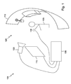
- the figure 1 illustrates a schematic representation of a first device 100 according to the invention.
- a user 105 is preferably located in an environment 110 that can include various elements such as furniture and plants, facing a screen 115 having a mirror role.
- the image projected on the screen 115 is the modified image of the real scene 120, filmed by the video camera 125.
- the video stream from the camera 125 is transmitted to a computer 130 which retransmits the video stream from the camera 125 on screen 115 after modifying it.
- the computer 130 has the particular role of inserting one or more virtual objects, animated or not, in the images of the video stream from the camera 125.
- the position and orientation of the virtual object are partially determined, in the actual scene 120, by a sensor 135 connected to the computer 130.
- the sensor 135 may be a sensor with 6 degrees of freedom for determining a position and an orientation (X, Y, Z, heading, pitch, roll). in the real scene 120.
- this sensor may be the "Fastrack” sensor of the company Polhemus (Fastrack is a registered trademark).
- the sensor 135 is a sensor with 3 degrees of freedom for determining an orientation (heading, pitch, roll), the position of the sensor (X, Y, Z) being determined by visual analysis of the images from the camera 125.
- the Fusion software thus makes it possible to visualize in real time the synthesis objects according to the determined position and orientation.
- the user can also interact with other virtual objects inserted into the video stream.
- the device 200 is for example a microcomputer, a workstation or a game console.
- the communication bus allows communication and interoperability between the various elements included in the device 200 or connected to it.
- the representation of the bus is not limiting and, in particular, the central unit is capable of communicating instructions to any element of the apparatus 200 directly or via another element of the apparatus 200.
- the executable code of each program allowing the programmable device to implement the processes for implementing the invention can be stored, for example, in the hard disk 220 or in the read-only memory 206.
- the executable code of the programs may be received via the communication network 228, via the interface 226, to be stored in the same manner as that described previously.
- the memory cards can be replaced by any information medium such as, for example, a compact disc (CD-ROM or DVD).
- memory cards can be replaced by information storage means, readable by a computer or by a microprocessor, integrated or not integrated into the device, possibly removable, and adapted to store one or more programs whose execution allows the implementation of the invention.
- program or programs may be loaded into one of the storage means of the device 200 before being executed.
- the central unit 204 will control and direct the execution of the instructions or portions of software code or programs for implementing the invention, instructions that are stored in the hard disk 220 or in the ROM 206 or in the other storage elements mentioned above.
- the program or programs that are stored in a non-volatile memory for example the hard disk 220 or the read-only memory 206, are transferred into the random access memory 208 which then contains the executable code of the program or programs enabling the implementation of the invention, as well as registers for storing the variables and parameters necessary for the implementation of the invention.
- the communication apparatus comprising the device according to the invention can also be a programmed apparatus.
- This device then contains the code of the computer program or programs for example frozen in a specific application integrated circuit (ASIC).
- ASIC application integrated circuit
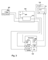
- the figure 3 schematically illustrates an example of the device, mentioned above, in which a sensor with six degrees of freedom is used.
- a screen 115 and a camera 125 are connected to a computer 130 '.
- a handle 300 is also connected to the computer 130 'via a housing 305.
- the video camera 125 is preferably a video camera provided with a wide angle optics to allow the user to be close to the screen.
- the video camera 125 is for example a Sony HDR HC1 camera equipped with a Sony VCLHG0737Y lens.
- the computer 130 comprises a video acquisition card 210 connected to the video camera 125, a graphics card 216 connected to the screen 115, a first communication port 214-1 (COM1) connected to the position sensor and orientation of the handle 300 via the housing 305 and a second communication port 214-2 (COM2) connected to a "trigger" type contactor of the handle 300, preferably via the housing 305.
- trigger type contactor It must be understood a switch to open or close the corresponding electrical circuit in a timely manner by exerting pressure on the trigger. The use of such a contactor increases the interactivity between the user and the computer software 130 '.
- the contactor 310 makes it possible, for example, to simulate a shot in a game software.
- the video acquisition card is, for example, a Decklinck PCIe card.
- the graphics card is a 3D graphics card for inserting computer graphics into a video stream, for example an ATI X1800XL card or an ATI 1900XT card.
- ATI X1800XL ATI X1800XL card
- ATI 1900XT ATI 1900XT card.
- the illustrated example uses two communication ports (COM1 and COM2), it should be understood that other communication interfaces may be used between the computer 130 'and the handle 300.
- the computer 130 'advantageously comprises a sound card 320 connected to speakers (HP) integrated in the screen 115.
- the link between the video acquisition card 210 and the video camera 125 can be established according to one of the following standards: composite video, SVideo, HDMI, YUV, YUV-HD, SDI, HD-SDI or USB / USB2.
- the connection between the graphics card 216 and the screen 115 can be established according to one of the following standards: composite video, Svideo, YUV, YUV-HD, SDI, HD-SDI, HDMI, VGA.
- the link between the communication ports 214-1 and 214-2, the sensor and the "trigger" type contactor of the handle 300 may be of the RS-232 type.
- the computer 130 is, for example, a standard PC equipped with an Intel Pentium IV processor having a frequency of 3GHz, 3Gbyte of RAM memory, a hard disk of 120Gbyte and two PCI express interfaces ( Peripheral Component Interconnect ) for the capture card and for the graphics card.
- Intel Pentium IV processor having a frequency of 3GHz, 3Gbyte of RAM memory, a hard disk of 120Gbyte and two PCI express interfaces ( Peripheral Component Interconnect ) for the capture card and for the graphics card.
- the handle 300 preferably comprises a position and orientation sensor with six degrees of freedom 135 ', for example a "Fastrack” sensor from the company Polhemus, and a "trigger" contactor 310.
- a position and orientation sensor with six degrees of freedom 135 ', for example a "Fastrack” sensor from the company Polhemus, and a "trigger” contactor 310.
- An example of the handle 300 is illustrated on the figure 4 .
- the housing 305 forms an interface between the handle 300 and the computer 130 '.
- the housing 305 associated with the position and orientation sensor, is intended to transform the signals from the sensor data usable by the computer 130 '.
- the housing 305 comprises a motion capture module 315 and, advantageously, a transmitter 320 enabling wireless transmission of the signals from the sensor 135 'to the housing 305.
- the figure 4 illustrates an example of a handle 300 comprising the sensor 135 'and the "trigger" type contactor 310.
- the handle 300 is typically a pistol used for indoor arcade games, such as the 45-caliber optical pistol marketed by the company. Happ in the United States of America.
- the barrel of the pistol is advantageously removed to obtain a handle and the original electronics is removed to keep only the trigger type contactor 310.
- the position and orientation sensor 135 ' is inserted into the handle.
- the sensor wire and the wire of the trigger are inserted into the electrical connecting duct between the handle and the capture box 305.
- a DB9 type connector is advantageously arranged at the other end of the electrical sheath so that when the user pulls the trigger, the contactor closes, and pins 8 and 7 of the serial port are connected to each other via a 4.7 K ⁇ resistor.
- the electrical sheath is removed and a wireless communication module is inserted into the handle 300.
- the data from the sensor 135 ' is transmitted to the housing 305 without wire connection.
- the "trigger" contactor is then inactive unless it is also coupled to a wireless communication module.
- the figure 5 illustrates an example of implementation of the device illustrated by the figures 3 and 4 (According to the embodiment in which the data is transmitted by a wired connection between the handle and the motion capture box).
- the figure 5a represents a side view, in section, of the device while the figure 5b illustrates a perspective view of this device.
- a user 105 is facing a device 500 comprising a screen 115 preferably located facing the user 105 and approximately at the height of his eyes.
- the device 500 also includes a video camera 125 located near the screen 125, a motion capture box 305 and a computer 130 'to which the video camera 125, the screen 115 and the motion capture box 305 are connected as shown. 'indicated above.
- the user 105 has a handle 300 'connected to the motion capture box 305 by a wire link.
- a background of uniform color for example a blue background or a green background, is placed behind the user.
- This uniform background is used by the software to "cut off" the user, that is to say to extract it from the images from the video camera 115, and to embed it in a synthesis scene or in a secondary video stream.
- the Fusion software uses its ability to perform a chroma key function (inlay of a second image in a first according to a color identified in the first) in real time thanks to a pixel shader function that performs processing on the video stream from the camera.
- the device described above gives any satisfaction in terms of result, the position sensor and orientation to six degrees of freedom has a price that can make it prohibitive for personal use.
- the device according to the invention is based on the use of an inexpensive motion sensor combined with an image processing module making it possible to obtain the position and the orientation of the sensor according to six degrees of freedom.
- the figure 6 schematically illustrates the device according to this embodiment.
- the device comprises a computer 130 "connected to a screen 115, a video camera 125 and a handle 600.
- the computer 130" differs from the computer 130 'in particular in that it comprises an image processing module 605 adapted to determine the position of the handle 600.
- the video rendering module 610 is similar to that present in the computer 130 '(not shown) and can also use the Fusion software.
- the characteristics of the 130 'and 130' computers are similar, software equivalent to the software Fusion can be used to combine video streams with virtual objects (3D rendering module 610), and capture the position information of the handle by image analysis (image processing module 605).
- the video camera 125 may be similar to the video camera shown previously or may be a simple webcam.
- the handle 600 is advantageously connected to the computer 130 "by a wireless link, without a motion capture box
- the handle 600 comprises an orientation sensor 135" capable of determining the orientation of the handle 600 in three degrees of freedom.
- the orientation sensor 135 is, for example, the angular sensor MT9B from the company Xsens or the angular sensor Inertia Cube 3 from the company Intersense, in its wired or non-wired version, the orientation data coming from the sensor can be transmitted via a COM port or by a specific wireless protocol
- one or more "trigger" type contactors 310 are present in the handle 600.
- the handle 600 also comprises a geometric element having a particular shape, making it possible to locate the handle 600 when it is visible on an image.
- This geometric shape is, for example, a colored sphere whose diameter is a few centimeters.However, other shapes may be used, in particular a cube, a plane or a polyhedron.
- the handle 600 is preferably notched forcing the user to hold it in a predetermined direction (the fingers are positioned according to the notch) for pe give consistent positioning of the angle sensor.
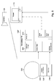
- FIG 7 illustrates an example of a 600 handle.
- figure 7a illustrates an overview of the handle 600 while the Figures 7b and 7c represent the electrical diagram of this handle.
- the handle 600 comprises a lower part, also called the handle, intended to be held by the user inside which there is a battery 700, for example a lithium battery, a wireless communication module 705 and trigger-type contactors 310.
- the angular sensor 135 is preferably attached to the upper part of the handle, and the upper part of the handle advantageously comprises a thread on its periphery for mounting the geometric element used to identify the position of the handle.
- the geometric element is the sphere 615 which comprises an opening adapted to be screwed onto the upper part of the handle. It should be understood that other means of fixing the geometric element on the handle can be used such as gluing or casing.
- a light source such as a bulb or a LED ( light-emitting diode ) is disposed within the sphere 615 which is preferably made of a transparent or translucent material.
- This light source and all the electrical components of the handle 600 are activated at the request of the user or, for example, as soon as the handle 600 is detached from the support 715 used for storing the handle and, advantageously, for charging the battery 700.
- the support 700 is connected to an electrical source.
- the figure 7b illustrates the circuit diagram of a first assembly of the electrical elements of the handle 600.
- the battery 700 is connected to the orientation sensor 135 ", the trigger type contactor 310, the wireless transmission module 705 and the source 710 to provide a power supply
- a switch 720 is disposed at the output of the battery 700 to allow to cut or activate the power supply of the orientation sensor 135 ", the trigger type contactor 310, the wireless transmission module 705 and the light source 710.
- the switch 720 can be controlled manually by the user or automatically, for example when the handle 600 is extracted from the support 715. It is also possible to modify the connection diagram of the battery 700 so that the switch only controls some of the aforementioned elements. It is also possible to use several switches to independently control these elements to allow, for example, to use the handle 600 without activating the light source 710.
- the orientation sensor 135 "and the" trigger “contactor 310 are connected to the wireless transmission module 705 to transfer the information from the sensor 135" and the contactor 310 to the computer 130 ".
- the wireless transmission module 705 is for example a high frequency (HF) module such as a Bluetooth or WiFi module.
- HF high frequency
- a corresponding wireless communication module is connected to the computer 130 "to receive the signals emitted by the handle 600. This module can be connected to the computer 130" using, for example, a USB interface / USB2 or RS-232.
- a sheath 725 comprising wires for feeding the handle 600 and for transmitting the signals from the sensor 135 "and the contactor 310 connects the handle 600 to the computer 130".
- the handle 600 avoids uncertainty as to the relative orientation of the hand relative to that of the sensor through the use of a notch on the handle.
- the geometric element used to determine the position of the handle is easily visible in an image while allowing a large number of movements to the user. This geometric element can be easily disassembled to change its color and shape. Finally, the presence of a light source placed in the geometric element or on its surface makes it possible to improve the tracking of this object in poor lighting conditions.
- the computer 130 "analyzes the images from the video camera or webcam 125 on which is present the geometric element of the handle 600. In this step, it is essential to find precisely the position of the center of the geometric element in the images from the camera used
- the solution used is based on a new color space and a new filtering approach to improve the quality of the results obtained.
- step 825 it is preferable to estimate the desired position theoretically (step 825) by linear extrapolation of the position of the geometric element over time and to compare the estimated position with the position obtained by analysis. of image (step 830).
- the principle of determining the position of the geometrical element consists, first of all, in detecting the zones of the image whose color corresponds to that of the searched geometric element.
- the HSL color space is preferred to the RGB color space.
- pixels After converting an RGB image to an HSL image, all pixels are selected and pixels whose luminance L is not in a predefined interval [ ⁇ L inf ; ⁇ L sup ] are deselected.
- the deselection of a pixel can be performed, for example, by imposing zero values for the luminance L, the saturation S and the hue H. Thus, all the selected pixels have non-zero values while the deselected pixels have values zero.
- Segmenting an image using an HSL color space gives results that are not entirely satisfactory because a very dark or very light pixel (but neither black nor white) can have almost any value hue (and change quickly because of the noise generated in the image during the acquisition) and therefore have a shade close to that sought.
- the HSL color space is modified to not take into account pixels that are too dark or too bright.
- a new saturation S ' is created.
- the weighting coefficient ⁇ preferably has a value between zero and one.
- the figure 9 illustrates the value of the weighting coefficient ⁇ as a function of luminance.
- the pixels whose saturation S 'is not greater than a predefined threshold ⁇ S' inf are then deselected.
- the pixels whose hue H does not correspond to the hue of the geometric element that is to say the pixels not belonging to an interval [ ⁇ H inf ; ⁇ H sup ] predetermined according to the hue of the geometric element, are deselected.
- the hue is theoretically expressed in degree, ranging from 0 to 360 °. Indeed, the hue is a cyclic concept, the "red" being at both ends (0 and 360).
- the value of the hue is recoded, according to the targeted applications, on the intervals [0,180 [, [0,240 [or [0,255].
- the interval [0.180] is preferred. It should be noted, however, that the loss caused by the change of scale has no significant effect on the results.
- the deselection of the pixels is preferably carried out according to the luminance order L, saturation S 'then hue H.
- the essential phase is the segmentation according to the hue H.
- the segmentation according to the luminance and the saturation makes it possible to improve the quality of the result as well as the overall performance, especially in that it allows to optimize the calculation time.
- Part of the pixel selection of the image represents the geometric element.
- a contour extraction step is implemented. This phase consists in extracting the contours of the groups of nonzero pixels using, for example, a convolution mask. It should be noted here that there are many contour extraction algorithms.
- the circle of minimum radius encompassing the contour is calculated and then the ratio between the area determined by the contour and the radius of the calculated circle is evaluated. It is then considered that the sought contour is the one offering the largest ratio. This ratio tends to represent the fact that the contour fully fills the circle that encompasses it and therefore simultaneously favors the contours with a circular tendency and the contours with the strongest radius.
- This criterion has the advantage of a relatively low calculation cost. Naturally, the selection criterion must be adapted to the shape of the geometric element.
- the colorimetric and geometric segmentations make it possible to obtain a circle representing approximately the projection of the sphere associated with the handle in the image.
- An advantage of this solution is that if the shape and color of the geometric element are unique in the environment, the recognition of this shape is robust to partial occlusions.
- the position of the geometric element in the space in which it is located is then determined from its projection in the image.
- the geometric element is located on the optical axis of the camera from which the image is derived.
- the projection of a sphere generally gives an ellipse.
- the circle is only obtained when the sphere is on the optical axis.
- such an approximation is sufficient to determine the position of the sphere by its apparent radius by a simple ratio of proportionality.
- the figure 10 illustrates the principle used to determine the distance of the sphere.
- C is the optical center, that is, the projection center corresponding to the position of the camera
- R is the physical radius of the sphere at a distance Z from the camera.
- this radius R is transformed into an apparent radius r m located on the screen plane at a distance f m which represents the metric focal length.
- the quality of the sphere radius estimation has a great influence on the Z positioning quality which, therefore, influences the quality of the X and Y positioning (which are also influenced by the quality of the estimated 2D position of the circle).
- This error in Z can be large metrically but also visually because the virtual object associated with the sensor is generally larger than the sphere and, consequently, an error by overestimation of the radius multiplies all the apparent size of the virtual object. inserted in the image that this object is larger (metrically) than the sphere.
- a major problem in finding the actual position of the geometric element is the lack of temporal stability of the estimated position (u, v) and radius of the circle. This problem results in a significant vibration of the position X, Y and Z of the virtual object associated with the sensor. To filter these vibrations, a particular filtering is used.
- This filtering is based on the principle that a low-pass filter prediction can be made and that if this prediction is close enough to the new measurement then this filtered value is applied. As soon as the prediction deviates from the measurement, a "wait-and-see" phase is implemented to check if the difference exists only on an isolated image of the video stream or if this difference is confirmed in time. The filtered value from the prediction is applied. If the first discrepancy is confirmed the actual value of the measurement is applied with a delay of an image in the video stream. Low-pass filtering is performed using orthogonal linear regression (orthogonal quadratic regression providing lower quality results) on the last n measures (excluding those considered abnormal).
- n is variable with a value that increases to a predetermined threshold as long as the predictions are consistent. As soon as a prediction is no longer correct, following a variation confirmed by the following image, the value of n drops to 4 for minimal filtering. This technique allows a better reactivity of the filtering and assumes that the vibrations are all the more visible as the radius is supposed to be rather constant. On the other hand, in movement, the vibrations are not very perceptible and it is thus possible to decrease the latency.
- the values a and b are estimated in order to predict a value for the coordinates (u, v) and for the apparent radius of the sphere, in order to deduce the coordinates (x, y, z) of the sphere in the real scene.
- These estimated values are used as a reference and are compared to the values determined by the the image as described previously. According to the result of the comparison, the values determined according to the analysis of the image are used in place of the predicted values or not.
- the augmented reality software determines the image of the virtual object to be inserted from the three-dimensional model of this object. object. This image of the virtual object is then inserted into the image of the real scene.
- the process of determining the position and orientation of the virtual object in the real scene, determining the image of the virtual object and inserting the image of the virtual object into an image of the actual scene is repeated for each image of the video stream from the camera.
- Augmented reality software can also be coupled to a game, allowing the user to see themselves in the game.
- a person skilled in the field of the invention may apply modifications in the foregoing description.
- a sensor present in the real scene, having at least three degrees of freedom.
- the only constraint is that the data from the sensor is complementary to the data from the image analysis. It is thus possible to use, for example, a sensor having two degrees of freedom and to obtain the information related to the other four degrees of freedom by image analysis.
- the handle comprising the position and orientation sensor may take other forms than those described.
Abstract
Description
La présente invention concerne la détermination de la position et de l'orientation d'un objet dans une scène réelle et plus particulièrement un dispositif permettant la détermination en temps réel de données de position et d'orientation du dispositif dans une scène réelle représentée par des images, ces images étant reçues par un ordinateur déterminant en temps réel des données de position et d'orientation du dispositif.The present invention relates to the determination of the position and orientation of an object in a real scene and more particularly to a device allowing the real-time determination of position and orientation data of the device in a real scene represented by images, these images being received by a computer determining in real time data of position and orientation of the device.
L'effet de miroir utilisant une caméra et un écran de visualisation est utilisé dans de nombreuses applications, notamment dans le domaine des jeux vidéo. Le principe de cette technologie consiste à acquérir une image en provenance d'une caméra de type webcam reliée à un ordinateur ou à une console. Cette image est de préférence stockée dans la mémoire du système auquel la caméra est reliée. Ensuite, un algorithme de suivi d'objet, aussi appelé blobs tracking, est utilisé pour calculer, en temps réel, les contours de certains éléments tels que la tête et les mains de l'utilisateur. La position de ces formes dans l'image permet de modifier ou de déformer certaines parties de l'image affichée. Cette solution permet de localiser une zone de l'image selon deux degrés de liberté.The mirror effect using a camera and a display screen is used in many applications, especially in the field of video games. The principle of this technology is to acquire an image from a webcam type camera connected to a computer or console. This image is preferably stored in the memory of the system to which the camera is connected. Then, an object tracking algorithm, also called blobs tracking, is used to calculate, in real time, the outlines of certain elements such as the user's head and hands. The position of these shapes in the image makes it possible to modify or deform certain parts of the displayed image. This solution makes it possible to locate an area of the image according to two degrees of freedom.
Pour déterminer la position et l'orientation selon lesquelles un objet virtuel doit être inséré dans une image représentant une scène réelle, une solution consiste à indiquer dans la scène réelle la position et l'orientation de l'objet virtuel. Une sphère peut être utilisée à cette fin. La taille de la sphère doit être suffisante pour permettre le calcul de sa position dans un espace tridimensionnel selon la position de celle-ci dans une représentation bidimensionnelle de cet espace et selon son diamètre apparent. L'orientation de la sphère peut être évaluée en plaçant des pastilles colorées sur la surface de celle-ci. Cette solution est efficace si la sphère a une taille suffisamment importante et si le système de capture d'image est de suffisamment bonne qualité, ce qui restreint les possibilités de mouvement de l'utilisateur, en particulier ses déplacements rapides.To determine the position and orientation by which a virtual object is to be inserted into an image representing a real scene, one solution is to indicate in the real scene the position and orientation of the virtual object. A sphere can be used for this purpose. The size of the sphere must be sufficient to allow the calculation of its position in a three-dimensional space according to the position of the latter in a two-dimensional representation of this space and according to its apparent diameter. The orientation of the sphere can be evaluated by placing colored pellets on the surface of the sphere. This solution is effective if the sphere has a sufficiently large size and if the image capture system is of sufficiently good quality, which restricts the possibilities of movement of the user, particularly his rapid movements.
Ces solutions n'offrent cependant pas les performances requises pour de nombreuses applications et il existe un besoin d'améliorer les performances de tels systèmes tout en maintenant leur prix à un niveau acceptable.These solutions, however, do not provide the performance required for many applications and there is a need to improve the performance of such systems while keeping their price at an acceptable level.
L'invention permet de résoudre au moins un des problèmes exposés précédemment.The invention solves at least one of the problems discussed above.
L'invention a ainsi pour objet un dispositif permettant la détermination en temps réel de données de position et d'orientation dudit dispositif dans une scène réelle représentée par des images, lesdites images étant reçues par un ordinateur déterminant en temps réel des données de position et d'orientation dudit dispositif, ce dispositif comprenant les moyens suivants,
- un élément géométrique, ledit élément géométrique étant adapté à la détermination, par analyse desdites images, d'au moins une donnée de position dudit dispositif dans ladite scène réelle lorsque ledit dispositif est visible dans lesdites images ; et,
- un capteur d'orientation, ledit capteur d'orientation déterminant au moins une donnée d'orientation dudit dispositif dans ladite scène réelle et transmettant ladite au moins une donnée d'orientation dudit dispositif audit ordinateur.
- a geometric element, said geometric element being adapted to determine, by analyzing said images, at least one position data of said device in said real scene when said device is visible in said images; and,
- an orientation sensor, said orientation sensor determining at least one orientation data of said device in said real scene and transmitting said at least one orientation data of said device to said computer.
Le dispositif selon l'invention permet ainsi la détermination rapide et précise de sa position et de son orientation dans une scène réelle sans recourir à des moyens onéreux. Il permet la combinaison de résultats d'analyse d'images, utilisée pour déterminer une position, avec des données d'orientation issues d'un capteur lié à ce dispositif.The device according to the invention thus allows the rapid and precise determination of its position and its orientation in a real scene without resorting to expensive means. It allows the combination of image analysis results, used to determine a position, with orientation data from a sensor related to this device.
Selon un mode de réalisation particulier, ledit élément géométrique est une sphère qui est facilement visible et identifiable dans une image. De façon avantageuse, ladite sphère est colorée et son diamètre est de quelques centimètres.According to a particular embodiment, said geometric element is a sphere that is easily visible and identifiable in an image. Advantageously, said sphere is colored and its diameter is a few centimeters.
La sphère est, de préférence, réalisée dans un matériau transparent ou translucide, le dispositif comprenant en outre, de préférence, une source de lumière disposée à l'intérieure de ladite sphère de telle sorte qu'elle soit facilement visible et identifiable même dans de mauvaises conditions d'éclairage.The sphere is preferably made of a transparent or translucent material, the device further comprising, preferably, a light source disposed within said sphere so that it is easily visible and identifiable even in poor lighting conditions.
Toujours selon un mode de réalisation particulier, ledit capteur d'orientation est un capteur capable de déterminer une orientation selon trois degrés de liberté. Un tel capteur est, par exemple, un capteur angulaire.Still according to a particular embodiment, said orientation sensor is a sensor capable of determining an orientation according to three degrees of freedom. Such a sensor is, for example, an angular sensor.
Toujours selon un mode de réalisation particulier, le dispositif comprend en outre un module de transmission sans fil pour transmettre ladite au moins une donnée d'orientation dudit dispositif audit ordinateur. Le dispositif est ainsi plus facilement manipulable par un utilisateur.Still according to a particular embodiment, the device further comprises a wireless transmission module for transmitting said at least one orientation datum of said device to said computer. The device is thus easier to manipulate by a user.
En outre, ledit dispositif comprend, de préférence, un manche sur lequel est fixé ledit élément géométrique, ledit dispositif étant cranté pour obliger un utilisateur à le tenir selon une direction prédéterminée. Le dispositif permet ainsi d'éviter une incertitude quant à l'orientation relative de la main d'un utilisateur par rapport à celle du capteur utilisé.In addition, said device preferably comprises a handle on which is fixed said geometric element, said device being notched to force a user to hold it in a predetermined direction. The device thus makes it possible to avoid uncertainty as to the relative orientation of the hand of a user with respect to that of the sensor used.
Selon un mode de réalisation particulier, le dispositif comprend en outre une source électrique, ladite source électrique alimentant au moins ledit capteur d'orientation et, de préférence, ladite source de lumière, et au moins un interrupteur relié à ladite source électrique pour contrôler l'alimentation électrique d'au moins un composant électrique dudit dispositif. Ladite source électrique est avantageusement une batterie rechargeable.According to a particular embodiment, the device further comprises an electrical source, said electrical source supplying at least said orientation sensor and, preferably, said light source, and at least one switch connected to said electrical source for controlling the light source. supplying electrical power to at least one electrical component of said device. Said electrical source is advantageously a rechargeable battery.
D'autres avantages, buts et caractéristiques de la présente invention ressortent de la description détaillée qui suit, faite à titre d'exemple non limitatif, au regard des dessins annexés dans lesquels :
- la
figure 1 représente schématiquement un premier dispositif selon l'invention ; - la
figure 2 montre un exemple d'appareil permettant de mettre en oeuvre au moins partiellement l'invention ; - la
figure 3 illustre schématiquement un exemple du dispositif dans lequel un capteur à six degrés de liberté est utilisé ; - la
figure 4 illustre un exemple de la poignée présenté sur lafigure 3 comprenant un capteur à six degrés de liberté et un contacteur de type « gâchette» ; - la
figure 5 , comprenant lesfigures 5a et5b , illustre un exemple de mise en oeuvre du dispositif illustré par lesfigures 3 et4 ; - la
figure 6 illustre schématiquement le dispositif selon l'invention ; - la
figure 7 , comprenant lesfigures 7a, 7b et 7c , illustre un exemple de la poignée représentée sur lafigure 6 . Lafigure 7a illustre une vue d'ensemble de la poignée tandis que lesfigures 7b et 7c représentent des exemples de schéma électrique de cette poignée ; - la
figure 8 illustre certaines étapes de l'algorithme utilisé pour déterminer laposition 3D d'un élément géométrique dans une représentation d'une scène réelle ; - la
figure 9 représente la variation du coefficient de pondération α utilisé pour pondérer la saturation en fonction de la luminance lors de la conversion d'une image ; et, - la
figure 10 illustre le principe utilisé pour déterminer la distance entre une sphère et une caméra à partir d'une image issue de cette caméra.
- the
figure 1 schematically represents a first device according to the invention; - the
figure 2 shows an example of apparatus for implementing at least partially the invention; - the
figure 3 schematically illustrates an example of the device in which a sensor with six degrees of freedom is used; - the
figure 4 illustrates an example of the handle presented on thefigure 3 comprising a sensor with six degrees of freedom and a trigger type contactor; - the
figure 5 , includingfigures 5a and5b , illustrates an example of implementation of the device illustrated by thefigures 3 and4 ; - the
figure 6 schematically illustrates the device according to the invention; - the
figure 7 , includingFigures 7a, 7b and 7c , illustrates an example of the handle shown on thefigure 6 . Thefigure 7a illustrates an overview of the handle while theFigures 7b and 7c represent examples of electrical diagram of this handle; - the
figure 8 illustrates some steps of the algorithm used to determine the 3D position of a geometric element in a representation of a real scene; - the
figure 9 represents the variation of the weighting coefficient α used to weight the saturation as a function of luminance during the conversion of an image; and, - the
figure 10 illustrates the principle used to determine the distance between a sphere and a camera from an image from this camera.
Selon l'invention, les données relatives au positionnement et à l'orientation d'un objet virtuel devant être inséré dans une représentation d'une scène réelle sont partiellement issues d'un capteur situé dans la scène réelle.According to the invention, the data relating to the positioning and the orientation of a virtual object to be inserted into a representation of a real scene are partially derived from a sensor located in the real scene.
La
Le capteur 135 peut être un capteur à 6 degrés de liberté permettant de déterminer une position et une orientation (X, Y, Z, cap, tangage, roulis) dans la scène réelle 120. A titre d'illustration, ce capteur peut être le capteur « Fastrack» de la société Polhemus (Fastrack est une marque déposée). Cependant, conformément à l'invention, le capteur 135 est un capteur à 3 degrés de liberté permettant de déterminer une orientation (cap, tangage, roulis), la position du capteur (X, Y, Z) étant déterminée par analyse visuelle des images issues de la caméra 125.The
Le système 100 est ainsi constitué des éléments suivants :
- un écran de visualisation (par exemple un écran LCD (Liquid cristal display), un écran plasma ou un écran de projection vidéo) ;
- un capteur permettant de définir une orientation selon trois degrés de liberté et optionnellement un capteur permettant de définir une position selon trois degrés de liberté ;
- une caméra vidéo située, de préférence, proche de l'écran et dans l'axe de celui-ci pour éviter des effets de parallaxe ;
- un ordinateur (par exemple un ordinateur de type PC, ou Personal Computer) en charge des opérations suivantes,
- acquisition vidéo en temps réel du signal vidéo en provenance de la caméra (le signal vidéo peut être, par exemple, un signal au format PAL (Phase Alternated Line), NTSC (National Television System Committee), YUV (Luminance-Bandwidth-Chrominance), YUV-HD (Luminance-Bandwidth-Chrominance High Definition), SDI (Serial Digital Interface) ou HD-SDI (High Definition Serial Digital Interface) transmis, par exemple, selon une connexion HDMI (High-Definition Multimedia Interface) ou USB/USB2 (Universal Serial Bus)) ;
- acquisition en temps réel du flux de données en provenance du capteur de mouvement et, selon le mode de réalisation, du capteur de position ;
- génération d'images de réalité augmentée, en temps réel, via la sortie de la carte graphique de l'ordinateur (cette sortie peut être, par exemple, du type VGA (Video Graphics Array), DVI (Digital Visual Interface), HDMI, SDI, HD-SDI, YUV, YUV-HD) ; et,
- opérer, de préférence, une symétrie sur l'image finale de telle sorte que le bord gauche de l'image devienne le bord droit afin de restituer l'effet « miroir ».
- a display screen (for example an LCD ( Liquid crystal display ), a plasma screen or a video projection screen);
- a sensor for defining an orientation with three degrees of freedom and optionally a sensor for defining a position with three degrees of freedom;
- a video camera preferably located near the screen and in the axis thereof to avoid parallax effects;
- a computer (for example a computer of PC type, or Personal Computer ) in charge of the following operations,
- real-time video acquisition of the video signal from the camera (the video signal can be, for example, a signal in PAL format ( Phase Alternated Line ), NTSC ( National Television System Committee ), YUV ( Luminance-Bandwidth-Chroma ) , YUV-HD ( Luminance-Bandwidth-Chrominance High Definition ), SDI ( Serial Digital Interface ) or HD-SDI ( High Definition Serial Digital Interface ) transmitted, for example, according to an HDMI connection ( High-Definition Multimedia Interface ) or USB / USB2 (Universal Serial Bus ));
- real-time acquisition of the data stream from the motion sensor and, depending on the embodiment, the position sensor;
- generation of augmented reality images, in real time, via the output of the graphics card of the computer (this output may be, for example, of the VGA type ( Video Graphics Array ), DVI ( Digital Visual Interface ), HDMI, SDI, HD-SDI, YUV, YUV-HD); and,
- operate, preferably, a symmetry on the final image so that the left edge of the image becomes the right edge in order to restore the effect "mirror".
L'ordinateur comprend une application de réalité augmentée telle que le logiciel D'Fusion de la société Total Immersion (D'Fusion est une marque de la société Total Immersion) pour générer une scène de réalité augmentée interactive à l'aide, par exemple, des fonctions suivantes :
- acquisition en temps réel du flux de données de mouvement ; et,
- ajout en temps réel de représentations bidimensionnelles d'objets de synthèse tridimensionnels dans le flux vidéo issu de la caméra et transmission du flux vidéo modifié à l'écran de visualisation.
- real-time acquisition of the motion data stream; and,
- adding in real time two-dimensional representations of three-dimensional synthesis objects in the video stream from the camera and transmission of the modified video stream to the display screen.
Le principe de ce type d'application est décrit dans la demande de brevet
Le logiciel D'Fusion permet ainsi de visualiser en temps réel les objets de synthèse selon la position et l'orientation déterminées. L'utilisateur peut également interagir avec d'autres objets virtuels insérés dans le flux vidéo.The Fusion software thus makes it possible to visualize in real time the synthesis objects according to the determined position and orientation. The user can also interact with other virtual objects inserted into the video stream.
Un appareil permettant de mettre en oeuvre l'invention ou une partie de l'invention est illustré sur la
L'appareil 200 comporte de préférence un bus de communication 202 auquel sont reliés :
- une unité centrale de traitement ou microprocesseur 204 (CPU, Central Processing Unit) ;
- une mémoire morte 206 (ROM, Read Only Memory) pouvant comporter le système d'exploitation et des programmes tels que "Prog" ;
- une mémoire vive ou mémoire cache 208 (RAM, Random Access Memory) comportant des registres adaptés à enregistrer des variables et paramètres créés et modifiés au cours de l'exécution des programmes précités ;
- une carte d'acquisition vidéo 210 reliée à une caméra 212 ;
- une carte d'acquisition de données 214 reliée à un capteur (non représenté) ; et,
- une carte graphique 216 reliée à un écran ou à
un projecteur 218.
- a central processing unit or microprocessor 204 (CPU, Central Processing Unit );
- a ROM 206 ( Read Only Memory ) which may include the operating system and programs such as "Prog";
- a random access memory or RAM ( Random Access Memory ) 208 having registers adapted to record variables and parameters created and modified during the execution of the aforementioned programs;
- a
video acquisition card 210 connected to acamera 212; - a
data acquisition card 214 connected to a sensor (not shown); and, - a
graphics card 216 connected to a screen or aprojector 218.
Optionnellement, l'appareil 200 peut également disposer des éléments suivants :
- un disque dur 220 pouvant comporter les programmes "Prog" précités et des données traitées ou à traiter permettant la mise en oeuvre de l'invention ;
un clavier 222 et une souris 224 ou tout autre dispositif de pointage comme un crayon optique, un écran tactile ou une télécommande permettant à l'utilisateur d'interagir avec les programmes permettant la mise en oeuvre de l'invention ;- une interface de
communication 226 reliée à un réseau decommunication distribué 228, par exemple le réseau Internet, l'interface étant apte à transmettre et à recevoir des données ; et, - un lecteur de cartes mémoires (non représenté) adapté à y lire ou à y écrire des données traitées ou à traiter permettant la mise en oeuvre de l'invention.
- a
hard disk 220 which may include the aforementioned "Prog" programs and data processed or to be processed allowing the implementation of the invention; - a
keyboard 222 and amouse 224 or any other pointing device such as an optical pen, a touch screen or a remote control allowing the user to interact with the programs for implementing the invention; - a
communication interface 226 connected to a distributedcommunication network 228, for example the Internet network, the interface being able to transmit and receive data; and, - a memory card reader (not shown) adapted to read or write processed or processed data allowing the implementation of the invention.
Le bus de communication permet la communication et l'interopérabilité entre les différents éléments inclus dans l'appareil 200 ou reliés à lui. La représentation du bus n'est pas limitative et, notamment, l'unité centrale est susceptible de communiquer des instructions à tout élément du l'appareil 200 directement ou par l'intermédiaire d'un autre élément du l'appareil 200.The communication bus allows communication and interoperability between the various elements included in the
Le code exécutable de chaque programme permettant à l'appareil programmable de mettre en oeuvre les processus permettant la mise en oeuvre de l'invention, peut être stocké, par exemple, dans le disque dur 220 ou en mémoire morte 206.The executable code of each program allowing the programmable device to implement the processes for implementing the invention can be stored, for example, in the
Selon une variante, le code exécutable des programmes pourra être reçu par l'intermédiaire du réseau de communication 228, via l'interface 226, pour être stocké de façon identique à celle décrite précédemment.According to one variant, the executable code of the programs may be received via the
Les cartes mémoires peuvent être remplacées par tout support d'information tel que, par exemple, un disque compact (CD-ROM ou DVD). De manière générale, les cartes mémoires peuvent être remplacées par des moyens de stockage d'information, lisibles par un ordinateur ou par un microprocesseur, intégrés ou non à l'appareil, éventuellement amovibles, et adaptés à mémoriser un ou plusieurs programmes dont l'exécution permet la mise en oeuvre de l'invention.The memory cards can be replaced by any information medium such as, for example, a compact disc (CD-ROM or DVD). In general, memory cards can be replaced by information storage means, readable by a computer or by a microprocessor, integrated or not integrated into the device, possibly removable, and adapted to store one or more programs whose execution allows the implementation of the invention.
De manière plus générale, le ou les programmes pourront être chargés dans un des moyens de stockage de l'appareil 200 avant d'être exécutés.More generally, the program or programs may be loaded into one of the storage means of the
L'unité centrale 204 va commander et diriger l'exécution des instructions ou portions de code logiciel du ou des programmes permettant la mise en oeuvre de l'invention, instructions qui sont stockées dans le disque dur 220 ou dans la mémoire morte 206 ou bien dans les autres éléments de stockage précités. Lors de la mise sous tension, le ou les programmes qui sont stockés dans une mémoire non volatile, par exemple le disque dur 220 ou la mémoire morte 206, sont transférés dans la mémoire vive 208 qui contient alors le code exécutable du ou des programmes permettant la mise en oeuvre de l'invention, ainsi que des registres pour mémoriser les variables et paramètres nécessaires à la mise en oeuvre de l'invention.The
Il convient de noter que l'appareil de communication comportant le dispositif selon l'invention peut également être un appareil programmé. Cet appareil contient alors le code du ou des programmes informatiques par exemple figé dans un circuit intégré à application spécifique (ASIC).It should be noted that the communication apparatus comprising the device according to the invention can also be a programmed apparatus. This device then contains the code of the computer program or programs for example frozen in a specific application integrated circuit (ASIC).
La
L'ordinateur 130' comprend une carte d'acquisition vidéo 210 reliée à la caméra vidéo 125, une carte graphique 216 reliée à l'écran 115, un premier port de communication 214-1 (COM1) relié au capteur de position et d'orientation de la poignée 300 via le boîtier 305 et un second port de communication 214-2 (COM2) relié à un contacteur de type « gâchette » de la poignée 300, de préférence via le boîtier 305. Par contacteur de type « gâchette » il doit être compris un interrupteur permettant d'ouvrir ou de fermer le circuit électrique correspondant de façon ponctuelle en exerçant une pression sur la gâchette. L'utilisation d'un tel contacteur permet d'accroître l'interactivité entre l'utilisateur et le logiciel de l'ordinateur 130'. Le contacteur 310 permet, par exemple, de simuler un tir dans un logiciel de jeu. La carte d'acquisition vidéo est, par exemple, une carte Decklinck PCIe. La carte graphique est une carte graphique 3D permettant d'insérer des images de synthèse dans un flux vidéo, par exemple une carte ATI X1800XL ou une carte ATI 1900XT. Bien que l'exemple illustré utilise deux ports de communication (COM1 et COM2), il doit être compris que d'autres interfaces de communication peuvent être utilisées entre l'ordinateur 130' et la poignée 300.The computer 130 'comprises a
L'ordinateur 130' comprend avantageusement une carte son 320 reliée à des haut-parleurs (HP) intégrés dans l'écran 115. La liaison entre la carte d'acquisition vidéo 210 et la caméra vidéo 125 peut être établie selon l'une des normes suivantes : vidéo composite, SVideo, HDMI, YUV, YUV-HD, SDI, HD-SDI ou USB/USB2. De même, la liaison entre la carte graphique 216 et l'écran 115 peut être établie selon l'une des normes suivantes : vidéo composite, Svideo, YUV, YUV-HD, SDI, HD-SDI, HDMI, VGA. La liaison entre les ports de communication 214-1 et 214-2, le capteur et le contacteur de type « gâchette » de la poignée 300 peut être du type RS-232. L'ordinateur 130' est, par exemple, un PC standard équipé d'un processeur Intel Pentium IV ayant une fréquence de 3GHz, de 3Gbyte de mémoire RAM, d'un disque dur de 120Gbyte et de deux interfaces PCI express (Peripheral Component Interconnect) pour la carte d'acquisition et pour la carte graphique.The computer 130 'advantageously comprises a
La poignée 300 comprend de préférence un capteur de position et d'orientation à six degrés de liberté 135', par exemple un capteur « Fastrack » de la société Polhemus, et un contacteur de type « gâchette » 310. Un exemple de la poignée 300 est illustré sur la
Le boîtier 305 constitue une interface entre la poignée 300 et l'ordinateur 130'. Le boîtier 305, associé au capteur de position et d'orientation, a pour objet de transformer les signaux issus du capteur en données exploitables par l'ordinateur 130'. Le boîtier 305 comprend un module 315 de capture de mouvement et, avantageusement, un émetteur 320 permettant une transmission sans fil des signaux du capteur 135' au boîtier 305.The
La
Alternativement, la gaine électrique est supprimée et un module de communication sans fil est inséré dans la poignée 300. Selon cette alternative, les données issues du capteur 135' sont transmises au boîtier 305 sans liaison filaire. Le contacteur de type « gâchette » est alors inactif à moins de la coupler également à un module de communication sans fil.Alternatively, the electrical sheath is removed and a wireless communication module is inserted into the
La
Selon un mode de réalisation particulier, un fond de couleur uniforme, par exemple un fond bleu ou un fond vert, est placé derrière l'utilisateur. Ce fond uniforme est utilisé par le logiciel pour « détourer » l'utilisateur, c'est-à-dire pour extraire celui-ci des images issues de la caméra vidéo 115, et pour l'incruster dans une scène de synthèse ou dans un flux vidéo secondaire. Pour insérer l'utilisateur dans une scène de synthèse, le logiciel D'Fusion utilise sa capacité à effectuer une fonction de chroma key (incrustation d'une seconde image dans une première selon une couleur identifiée dans la première) en temps réel grâce à une fonction de pixel shader (nuanceur de pixels) qui effectue des traitements sur le flux vidéo en provenance de la caméra.According to a particular embodiment, a background of uniform color, for example a blue background or a green background, is placed behind the user. This uniform background is used by the software to "cut off" the user, that is to say to extract it from the images from the
Alors que le dispositif décrit précédemment donne toute satisfaction en terme de résultat, le capteur de position et d'orientation à six degrés de liberté a un prix qui peut le rendre prohibitif pour un usage personnel. Pour surmonter cet inconvénient, le dispositif selon l'invention est basé sur l'usage d'un capteur de mouvement bon marché combiné avec un module de traitement d'image permettant d'obtenir la position et l'orientation du capteur selon six degrés de liberté.While the device described above gives any satisfaction in terms of result, the position sensor and orientation to six degrees of freedom has a price that can make it prohibitive for personal use. To overcome this drawback, the device according to the invention is based on the use of an inexpensive motion sensor combined with an image processing module making it possible to obtain the position and the orientation of the sensor according to six degrees of freedom.
La
La poignée 600 est avantageusement reliée à l'ordinateur 130" par une liaison sans fil, sans boîtier de capture de mouvement. La poignée 600 comprend un capteur d'orientation 135" capable de déterminer l'orientation de la poignée 600 selon trois degrés de liberté. Le capteur d'orientation 135" est, par exemple, le capteur angulaire MT9B de la société Xsens ou le capteur angulaire Inertia Cube 3 de la société Intersense, dans sa version filaire ou non filaire. Les données d'orientation issues du capteur peuvent être transmises via un port COM ou par un protocole spécifique sans fil. De préférence, un ou plusieurs contacteurs de type « gâchette » 310 sont présent dans la poignée 600. La poignée 600 comprend également un élément géométrique ayant une forme particulière, permettant de localiser la poignée 600 lorsque celle-ci est visible sur une image. Cette forme géométrique est, par exemple, une sphère colorée dont le diamètre est de quelques centimètres. Cependant, d'autres formes peuvent être utilisées, notamment un cube, un plan ou un polyèdre. La poignée 600 est de préférence crantée obligeant l'utilisateur à la tenir selon une direction prédéterminée (les doigts se positionnent selon le crantage) pour permettre un positionnement cohérent du capteur angulaire.The
La
Comme illustré, la poignée 600 comprend une partie inférieure, aussi appelée le manche, prévue pour être tenue par l'utilisateur à l'intérieure de laquelle se trouve une batterie 700, par exemple une batterie au lithium, un module de communication sans fil 705 et les contacteurs de type « gâchette » 310. Le capteur angulaire 135" est de préférence fixé sur la partie supérieure du manche. La partie supérieure du manche comprend avantageusement un filetage sur son pourtour permettant le montage de l'élément géométrique utilisé pour identifier la position de la poignée. Dans cet exemple, l'élément géométrique est la sphère 615 qui comprend une ouverture adaptée à être vissée sur la partie supérieure du manche. Il doit être compris que d'autres moyens de fixation de l'élément géométrique sur le manche peuvent être utilisés tels que le collage ou l'emboîtage. De façon avantageuse, une source de lumière telle qu'une ampoule ou une LED (light-emitting diode) est disposée à l'intérieur de la sphère 615 qui est de préférence constituée dans un matériau transparent ou translucide. Cette source lumineuse ainsi que l'ensemble des composants électriques de la poignée 600 sont activés à la demande de l'utilisateur ou, par exemple, dès que la poignée 600 est détachée du support 715 utilisé pour la rangement de la poignée et, avantageusement, pour le chargement de la batterie 700. Dans ce cas, le support 700 est connecté à une source électrique.As illustrated, the
La
Le capteur d'orientation 135" et le contacteur de type « gâchette » 310 sont reliés au module de transmission sans fil 705 pour transférer les informations issues du capteur 135" et du contacteur 310 à l'ordinateur 130". Le module de transmission sans fil 705 est par exemple un module haute fréquence (HF) tel qu'un module Bluetooth ou WiFi. Un module de communication sans fil correspondant est relié à l'ordinateur 130" pour recevoir les signaux émis par la poignée 600. Ce module peut être connecté à l'ordinateur 130" à l'aide, par exemple, d'une interface USB/USB2 ou RS-232.The
Alternativement, si une liaison filaire est utilisée entre la poignée 600 et l'ordinateur 130", la poignée 600 ne nécessite ni le module de communication sans fil 715 ni la batterie 700, l'ordinateur pouvant alimenter la poignée 600 en électricité. Cette alternative est illustrée sur la
La poignée 600 permet d'éviter une incertitude quant à l'orientation relative de la main par rapport à celle du capteur grâce à l'utilisation d'un crantage sur la poignée. L'élément géométrique utilisé pour déterminer la position de la poignée est aisément visible dans une image tout en permettant un grand nombre de mouvements à l'utilisateur. Cet élément géométrique peut être facilement démonté pour permettre de changer sa couleur et sa forme. Enfin, la présence d'une source lumineuse placée dans l'élément géométrique ou sur sa surface permet d'améliorer le suivi de cet objet dans des mauvaises conditions d'éclairage.The
Pour déterminer la position de la poignée, l'ordinateur 130" analyse les images issues de la caméra vidéo ou de la webcam 125 sur lesquelles est présent l'élément géométrique de la poignée 600. Dans cette étape, il est essentiel de trouver avec précision la position du centre de l'élément géométrique dans les images issues de la caméra utilisée. La solution utilisée est basée sur un nouvel espace de couleur et une nouvelle approche de filtrage pour améliorer la qualité des résultats obtenus.To determine the position of the handle, the
Certaines étapes de l'algorithme de recherche de la position de l'élément géométrique dans une image, illustrées sur la
- définition de seuils selon la couleur de l'élément géométrique (étape 800). Comme indiqué par l'utilisation de lignes pointillées, il n'est pas nécessaire de définir les seuils utilisés chaque fois qu'un élément géométrique est cherché dans une image. Ces seuils peuvent être prédéterminés lors du paramétrage de la poignée et/ou réévalués si nécessaire ;
- conversion de l'image RGB (Red-Green-Blue) vers un espace couleur de type HS'L (étape 805), dérivé de l'espace couleur de type HSL (Hue-Saturation-Luminance) et recherche par segmentation de l'image des régions de pixels qui correspondent à la couleur de l'élément géométrique (étape 810) ;
- reconstruction des contours de ces régions et recherche de celle qui se rapproche le plus de la forme de l'élément géométrique à traquer (étape 815); et,
- évaluation des dimensions de l'objet dans l'image afin de retrouver sa profondeur en fonction des dimensions mesurées initialement, recherche et calcul de la position du centre de l'élément géométrique dans l'image (étape 820).
- defining thresholds according to the color of the geometric element (step 800). As indicated by the use of dashed lines, it is not necessary to define the thresholds used each time a geometric element is searched in an image. These thresholds can be predetermined during the setting of the handle and / or reevaluated if necessary;
- conversion of the RGB ( Red-Green-Blue ) image to a color space of HS'L type (step 805), derived from HSL ( Hue-Saturation-Luminance ) color space and search by segmentation of the image of pixel regions that correspond to the color of the geometric element (step 810);
- reconstruction of the contours of these regions and search for the one that is closest to the shape of the geometric element to be tracked (step 815); and,
- evaluation of the dimensions of the object in the image in order to find its depth according to the dimensions measured initially, search and calculation of the position of the center of the geometric element in the image (step 820).
Pour améliorer la précision des résultats obtenus, il est préférable d'estimer la position recherchée de façon théorique (étape 825) par extrapolation linéaire de la position de l'élément géométrique dans le temps et de comparer la position estimée avec la position obtenue par analyse d'image (étape 830).To improve the accuracy of the results obtained, it is preferable to estimate the desired position theoretically (step 825) by linear extrapolation of the position of the geometric element over time and to compare the estimated position with the position obtained by analysis. of image (step 830).
Le principe de détermination de la position de l'élément géométrique consiste, dans un premier temps, à détecter les zones de l'image dont la couleur correspond à celle de l'élément géométrique recherché. Pour s'affranchir de la variabilité de luminosité, l'espace de couleur HSL est préféré à l'espace de couleur RGB.The principle of determining the position of the geometrical element consists, first of all, in detecting the zones of the image whose color corresponds to that of the searched geometric element. To overcome the brightness variability, the HSL color space is preferred to the RGB color space.
Après avoir converti une image RGB en image HSL, tous les pixels sont sélectionnés et les pixels dont la luminance L n'est pas dans un intervalle prédéfini [θLinf ;θLsup] sont désélectionnés. La désélection d'un pixel peut être réalisées, par exemple, en imposant des valeurs nulles pour la luminance L, la saturation S et la teinte H. Ainsi, tous les pixels sélectionnés ont des valeurs non nulles tandis que les pixels désélectionnés ont des valeurs nulles.After converting an RGB image to an HSL image, all pixels are selected and pixels whose luminance L is not in a predefined interval [θL inf ; θL sup ] are deselected. The deselection of a pixel can be performed, for example, by imposing zero values for the luminance L, the saturation S and the hue H. Thus, all the selected pixels have non-zero values while the deselected pixels have values zero.
La segmentation d'une image utilisant un espace de couleur HSL donne des résultats qui ne sont pas entièrement satisfaisants en raison du fait qu'un pixel très sombre ou très clair (mais ni noir, ni blanc) peut avoir quasi n'importe quelle valeur de teinte (et en changer rapidement à cause du bruit généré dans l'image lors de l'acquisition) et donc avoir une teinte proche de celle recherchée. Pour éviter cet inconvénient, l'espace de couleur HSL est modifié pour ne pas prendre en compte les pixels trop sombres ou trop clairs. Pour cela, une nouvelle saturation S' est créée. La saturation S' est dérivée de la saturation S à l'aide d'un coefficient de pondération α lié la luminance L selon la relation suivante S'= αS . Le coefficient de pondération α a de préférence une valeur comprise entre zéro et un. La
Les pixels dont la saturation S' n'est pas supérieure à un seuil prédéfini θS'inf sont ensuite désélectionnés. De même, les pixels dont la teinte H ne correspond pas à la teinte de l'élément géométrique, c'est-à-dire les pixels n'appartenant pas à un intervalle [θHinf ;θHsup] prédéterminé selon la teinte de l'élément géométrique, sont désélectionnés. Il convient de noter que la teinte est en théorie exprimée en degré, variant de 0 à 360°. En effet, la teinte est une notion cyclique le « rouge » étant au deux extrémités (0 et 360). D'un point de vue pratique 360 ne pouvant pas être codé sur un octet, la valeur de la teinte est recodée, selon les applications visées, sur les intervalles [0,180[, [0,240[ ou [0,255]. Pour optimiser le coût de calcul, l'intervalle [0,180[ est préféré. Il convient cependant de noter que la perte engendrée par le changement d'échelle n'a pas d'effet important sur les résultats.The pixels whose saturation S 'is not greater than a predefined threshold θS' inf are then deselected. Similarly, the pixels whose hue H does not correspond to the hue of the geometric element, that is to say the pixels not belonging to an interval [θH inf ; θH sup ] predetermined according to the hue of the geometric element, are deselected. It should be noted that the hue is theoretically expressed in degree, ranging from 0 to 360 °. Indeed, the hue is a cyclic concept, the "red" being at both ends (0 and 360). From a 360 practical point of view that can not be coded on a byte, the value of the hue is recoded, according to the targeted applications, on the intervals [0,180 [, [0,240 [or [0,255]. To optimize the calculation cost, the interval [0.180] is preferred. It should be noted, however, that the loss caused by the change of scale has no significant effect on the results.
La désélection des pixels est de préférence réalisée selon l'ordre luminance L, saturation S' puis teinte H. Cependant, la phase essentielle est la segmentation selon la teinte H. La segmentation selon la luminance et la saturation permet d'améliorer la qualité du résultat ainsi que les performances globales, notamment en ce qu'elle permet d'optimiser le temps de calcul.The deselection of the pixels is preferably carried out according to the luminance order L, saturation S 'then hue H. However, the essential phase is the segmentation according to the hue H. The segmentation according to the luminance and the saturation makes it possible to improve the quality of the result as well as the overall performance, especially in that it allows to optimize the calculation time.
Une partie de la sélection des pixels de l'image représente l'élément géométrique. Pour identifier cette partie, une étape d'extraction de contours est mise en oeuvre. Cette phase consiste à extraire les contours des groupes de pixels non nuls en utilisant, par exemple, un masque de convolution. Il convient de noter ici qu'il existe de nombreux algorithmes d'extraction de contours.Part of the pixel selection of the image represents the geometric element. To identify this part, a contour extraction step is implemented. This phase consists in extracting the contours of the groups of nonzero pixels using, for example, a convolution mask. It should be noted here that there are many contour extraction algorithms.
Il est ensuite nécessaire de déterminer parmi les contours celui qui se rapproche le plus de la forme de l'élément géométrique utilisé, ici un contour circulaire, l'élément géométrique utilisé étant une sphère.It is then necessary to determine among the contours that which is closest to the shape of the geometric element used, here a circular contour, the geometric element used being a sphere.
Tous les contours dont la taille, exprimée en nombre de pixels, est trop faible pour représenter un cercle de taille exploitable sont désélectionnés. Cette sélection est réalisée selon un seuil θT prédéterminé. De même, tous les contours dont l'aire, également exprimée en nombre de pixels, est trop faible sont supprimés. Cette sélection est à nouveau réalisée selon un seuil θA prédéterminé.All contours whose size, expressed in number of pixels, is too small to represent a circle of exploitable size are deselected. This selection is performed according to a predetermined threshold θ T. Similarly, all contours whose area, also expressed in number of pixels, is too small are deleted. This selection is again performed according to a predetermined threshold θ A.
Ensuite, pour chacun des contours restants, le cercle de rayon minimal englobant le contour est calculé puis le ratio entre l'aire déterminée par le contour et le rayon du cercle calculé est évalué. Il est alors considéré que le contour cherché est celui offrant le plus grand ratio. Ce ratio tend à représenter le fait que le contour rempli au maximum le cercle qui l'englobe et donc favorise simultanément les contours à tendance circulaire et les contours de plus fort rayon. Ce critère présente l'avantage d'un coût de calcul relativement faible. Naturellement, le critère de sélection doit être adapté à la forme de l'élément géométrique.Then, for each of the remaining contours, the circle of minimum radius encompassing the contour is calculated and then the ratio between the area determined by the contour and the radius of the calculated circle is evaluated. It is then considered that the sought contour is the one offering the largest ratio. This ratio tends to represent the fact that the contour fully fills the circle that encompasses it and therefore simultaneously favors the contours with a circular tendency and the contours with the strongest radius. This criterion has the advantage of a relatively low calculation cost. Naturally, the selection criterion must be adapted to the shape of the geometric element.
Les segmentations colorimétriques et géométriques permettent d'obtenir un cercle représentant approximativement la projection de la sphère associée à la poignée dans l'image. Un avantage de cette solution est que si la forme et la couleur de l'élément géométrique sont uniques dans l'environnement, la reconnaissance de cette forme est robuste aux occlusions partielles.The colorimetric and geometric segmentations make it possible to obtain a circle representing approximately the projection of the sphere associated with the handle in the image. An advantage of this solution is that if the shape and color of the geometric element are unique in the environment, the recognition of this shape is robust to partial occlusions.
La position de l'élément géométrique dans l'espace dans lequel il se trouve est ensuite déterminée à partir de sa projection dans l'image. Pour simplifier les calculs il est ici supposé que l'élément géométrique est situé sur l'axe optique de la caméra dont est issue l'image. En réalité, la projection d'une sphère donne en générale une ellipse. Le cercle n'est obtenu que lorsque la sphère se situe sur l'axe optique. Cependant, une telle approximation est suffisante pour déterminer la position de la sphère grâce à son rayon apparent par un simple rapport de proportionnalité.The position of the geometric element in the space in which it is located is then determined from its projection in the image. To simplify the calculations, it is assumed here that the geometric element is located on the optical axis of the camera from which the image is derived. In reality, the projection of a sphere generally gives an ellipse. The circle is only obtained when the sphere is on the optical axis. However, such an approximation is sufficient to determine the position of the sphere by its apparent radius by a simple ratio of proportionality.
La 
Il convient par ailleurs de noter que le ratio ![]()
![]()
où fp est la focale exprimée en pixel et rp est le rayon apparent de la sphère également exprimé en pixels. Il s'en déduit la relation suivante, 
![]()
![]()
where f p is the focal length expressed in pixels and r p is the apparent radius of the sphere also expressed in pixels. He deduces the following relation,
La projection d'un point de coordonnées (x, y, z) dans un repère dont l'origine est la caméra en coordonnées (u, v) dans l'image prise par la caméra s'exprime de la façon suivante, 
où (px, py) est la position, en pixels, du centre optique dans l'image. Cette relation permet d'en déduire les coordonnées réelles X et Y de la sphère lorsque sa coordonnée réelle Z et ses coordonnées u et v dans l'image, en pixels, sont connues, 
where (p x , p y ) is the position, in pixels, of the optical center in the image. This relation makes it possible to deduce the real coordinates X and Y of the sphere when its real coordinate Z and its coordinates u and v in the image, in pixels, are known,
Il est important de noter que la qualité de l'estimation du rayon de la sphère a une grande influence sur la qualité du positionnement Z qui, par conséquent, influe sur la qualité du positionnement X et Y (qui sont de surcroît aussi influencés par la qualité de la position 2D estimée du cercle). Cette erreur en Z peut être grande métriquement mais aussi visuellement car l'objet virtuel associé au capteur est en général plus gros que la sphère et, par conséquent, une erreur par surestimation du rayon démultiplie d'autant la taille apparente de l'objet virtuel inséré dans l'image que cet objet est plus grand (métriquement) que la sphère.It is important to note that the quality of the sphere radius estimation has a great influence on the Z positioning quality which, therefore, influences the quality of the X and Y positioning (which are also influenced by the quality of the estimated 2D position of the circle). This error in Z can be large metrically but also visually because the virtual object associated with the sensor is generally larger than the sphere and, consequently, an error by overestimation of the radius multiplies all the apparent size of the virtual object. inserted in the image that this object is larger (metrically) than the sphere.
Un problème important dans la recherche de la position réelle de l'élément géométrique vient du manque de stabilité temporelle de la position (u, v) et du rayon du cercle estimés. Ce problème se traduit en effet par une vibration importante de la position X, Y et Z de l'objet virtuel associé au capteur. Pour filtrer ces vibrations, un filtrage particulier est utilisé.A major problem in finding the actual position of the geometric element is the lack of temporal stability of the estimated position (u, v) and radius of the circle. This problem results in a significant vibration of the position X, Y and Z of the virtual object associated with the sensor. To filter these vibrations, a particular filtering is used.
Ce filtrage est basé sur le principe qu'une prédiction à base de filtre passe-bas peut être réalisée et que si cette prédiction est assez proche de la nouvelle mesure alors cette valeur filtrée est appliquée. Dès que la prédiction s'écarte de la mesure, une phase « attentiste » est mise en oeuvre pour vérifier si l'écart n'existe que sur une image isolée du flux vidéo ou si cet écart se confirme dans le temps. La valeur filtrée issue de la prédiction est appliquée. Si le premier écart est confirmé la valeur réelle de la mesure est appliquée avec un retard d'une image dans le flux vidéo. Le filtrage passe-bas est réalisé en utilisant une régression linéaire orthogonale (la régression quadratique orthogonale apportant des résultats de moindre qualité) sur les n dernières mesures (en excluant celles considérées comme anormales). La valeur de n est variable avec une valeur qui augmente jusqu'à un seuil prédéterminé tant que les prédictions sont conformes. Dès qu'une prédiction n'est plus conforme, suite à une variation confirmée par l'image suivante, la valeur de n chute à 4 pour un filtrage minimal. Cette technique permet une meilleur réactivité du filtrage et part du principe que les vibrations sont d'autant plus visibles que le rayon est censé être plutôt constant. Par contre, en mouvement, les vibrations sont peu perceptibles et il est donc possible de diminuer la latence.This filtering is based on the principle that a low-pass filter prediction can be made and that if this prediction is close enough to the new measurement then this filtered value is applied. As soon as the prediction deviates from the measurement, a "wait-and-see" phase is implemented to check if the difference exists only on an isolated image of the video stream or if this difference is confirmed in time. The filtered value from the prediction is applied. If the first discrepancy is confirmed the actual value of the measurement is applied with a delay of an image in the video stream. Low-pass filtering is performed using orthogonal linear regression (orthogonal quadratic regression providing lower quality results) on the last n measures (excluding those considered abnormal). The value of n is variable with a value that increases to a predetermined threshold as long as the predictions are consistent. As soon as a prediction is no longer correct, following a variation confirmed by the following image, the value of n drops to 4 for minimal filtering. This technique allows a better reactivity of the filtering and assumes that the vibrations are all the more visible as the radius is supposed to be rather constant. On the other hand, in movement, the vibrations are not very perceptible and it is thus possible to decrease the latency.
Les équation suivantes détaillent le calcul de régression orthogonale linéaire avec une droite d'équation y=a x + b, avec x correspondant à la valeur de la trame courante et y à la valeur des 3 paramètres u, v, et le rayon apparent de la sphère, devant être filtrer, chacun indépendamment.The following equations detail the computation of linear orthogonal regression with a line of equation y = ax + b, with x corresponding to the value of the current frame and y to the value of the 3 parameters u, v, and the apparent radius of the sphere, to be filtered, each independently.
L'erreur entre la régression orthogonale linéaire et la mesure du point pi(xi, yi) peut s'exprimer sous forme de la relation suivante, ![]()
![]()
Il est ainsi nécessaire de minimiser l'erreur quadratique totale E qui peut s'exprimer selon la relation suivante, 
en posant, 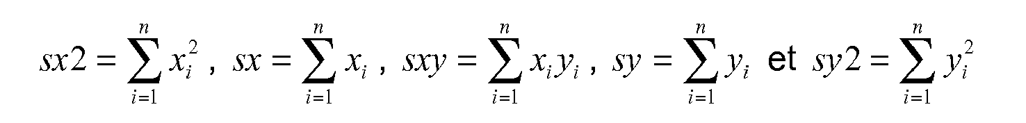
il en résulte que, ![]()
by asking,
it follows that, ![]()
La fonction E étant une fonction quadratique, elle admet son minimum lorsque, 
Par conséquent, 
avec det = sx2 · n - sx2 Therefore,
with det = sx2 · n - sx 2
Pour chaque image du flux vidéo issu de la caméra, les valeurs a et b sont estimées afin de prédire une valeur pour les coordonnées (u, v) et pour le rayon apparent de la sphère, afin d'en déduire les coordonnées (x, y, z) de la sphère dans la scène réelle. Ces valeurs estimées sont utilisées comme référence et sont comparées aux valeurs déterminées selon l'analyse de l'image comme décrit précédemment. Selon le résultat de la comparaison, les valeurs déterminées selon l'analyse de l'image sont utilisées à la place des valeurs prédites ou non.For each image of the video stream coming from the camera, the values a and b are estimated in order to predict a value for the coordinates (u, v) and for the apparent radius of the sphere, in order to deduce the coordinates (x, y, z) of the sphere in the real scene. These estimated values are used as a reference and are compared to the values determined by the the image as described previously. According to the result of the comparison, the values determined according to the analysis of the image are used in place of the predicted values or not.
Lorsque la position et l'orientation de l'objet virtuel sont déterminées dans la scène réelle, le logiciel de réalité augmentée, par exemple D'Fusion, détermine l'image de l'objet virtuel devant être insérée à partir du modèle tridimensionnel de cet objet. Cette image de l'objet virtuel est ensuite insérée dans l'image de la scène réelle.When the position and the orientation of the virtual object are determined in the real scene, the augmented reality software, for example D'Fusion, determines the image of the virtual object to be inserted from the three-dimensional model of this object. object. This image of the virtual object is then inserted into the image of the real scene.
Le processus de détermination de la position et de l'orientation de l'objet virtuel dans la scène réelle, de détermination de l'image de l'objet virtuel et d'insertion de l'image de l'objet virtuel dans une image de la scène réelle est répété pour chaque image du flux vidéo issu de la caméra.The process of determining the position and orientation of the virtual object in the real scene, determining the image of the virtual object and inserting the image of the virtual object into an image of the actual scene is repeated for each image of the video stream from the camera.
Le logiciel de réalité augmentée peut également être couplé à un jeu permettant ainsi à l'utilisateur de se voir « dans » le jeu.Augmented reality software can also be coupled to a game, allowing the user to see themselves in the game.
Naturellement, pour satisfaire des besoins spécifiques, une personne compétente dans le domaine de l'invention pourra appliquer des modifications dans la description précédente. En particulier, il n'est pas impératif d'utiliser un capteur, présent dans la scène réelle, ayant au moins trois degrés de liberté. La seule contrainte est que les données issues du capteur soient complémentaires des données issues de l'analyse d'image. Il est ainsi possible d'utiliser, par exemple, un capteur ayant deux degrés de liberté et d'obtenir les informations liées aux quatre autres degrés de liberté par analyse d'image. De même, la poignée comprenant le capteur de position et d'orientation peut prendre d'autres formes que celles décrites.Naturally, to meet specific needs, a person skilled in the field of the invention may apply modifications in the foregoing description. In particular, it is not imperative to use a sensor, present in the real scene, having at least three degrees of freedom. The only constraint is that the data from the sensor is complementary to the data from the image analysis. It is thus possible to use, for example, a sensor having two degrees of freedom and to obtain the information related to the other four degrees of freedom by image analysis. Similarly, the handle comprising the position and orientation sensor may take other forms than those described.
Claims (13)
Applications Claiming Priority (2)
| Application Number | Priority Date | Filing Date | Title |
|---|---|---|---|
| FR0752547A FR2911211B1 (en) | 2007-01-05 | 2007-01-05 | METHOD AND DEVICES FOR REAL-TIME INSERTING VIRTUAL OBJECTS IN AN IMAGE STREAM FROM DATA FROM THE REAL SCENE REPRESENTED BY THESE IMAGES |
| EP08761735.3A EP2104925B1 (en) | 2007-01-05 | 2008-01-03 | Method and device for the real time imbedding of virtual objects in an image stream using data from a real scene represented by said images |
Related Parent Applications (1)
| Application Number | Title | Priority Date | Filing Date |
|---|---|---|---|
| EP08761735.3 Division | 2008-01-03 |
Publications (2)
| Publication Number | Publication Date |
|---|---|
| EP2237231A1 true EP2237231A1 (en) | 2010-10-06 |
| EP2237231B1 EP2237231B1 (en) | 2013-05-01 |
Family
ID=38161918
Family Applications (2)
| Application Number | Title | Priority Date | Filing Date |
|---|---|---|---|
| EP08761735.3A Not-in-force EP2104925B1 (en) | 2007-01-05 | 2008-01-03 | Method and device for the real time imbedding of virtual objects in an image stream using data from a real scene represented by said images |
| EP10165722.9A Not-in-force EP2237231B1 (en) | 2007-01-05 | 2008-01-03 | Device for real-time determination of position and orientation data of the device in a real stage |
Family Applications Before (1)
| Application Number | Title | Priority Date | Filing Date |
|---|---|---|---|
| EP08761735.3A Not-in-force EP2104925B1 (en) | 2007-01-05 | 2008-01-03 | Method and device for the real time imbedding of virtual objects in an image stream using data from a real scene represented by said images |
Country Status (6)
| Country | Link |
|---|---|
| US (1) | US20100060632A1 (en) |
| EP (2) | EP2104925B1 (en) |
| JP (2) | JP5204126B2 (en) |
| KR (1) | KR101320134B1 (en) |
| FR (1) | FR2911211B1 (en) |
| WO (1) | WO2008099080A1 (en) |
Families Citing this family (38)
| Publication number | Priority date | Publication date | Assignee | Title |
|---|---|---|---|---|
| US8817045B2 (en) | 2000-11-06 | 2014-08-26 | Nant Holdings Ip, Llc | Interactivity via mobile image recognition |
| WO2007017598A2 (en) * | 2005-08-09 | 2007-02-15 | Total Immersion | Method and devices for visualising a digital model in a real environment |
| JP4890552B2 (en) * | 2005-08-29 | 2012-03-07 | エブリックス・テクノロジーズ・インコーポレイテッド | Interactivity via mobile image recognition |
| US8339418B1 (en) * | 2007-06-25 | 2012-12-25 | Pacific Arts Corporation | Embedding a real time video into a virtual environment |
| WO2010029553A1 (en) | 2008-09-11 | 2010-03-18 | Netanel Hagbi | Method and system for compositing an augmented reality scene |
| US20110279475A1 (en) * | 2008-12-24 | 2011-11-17 | Sony Computer Entertainment Inc. | Image processing device and image processing method |
| FR2947348B1 (en) * | 2009-06-25 | 2011-08-19 | Immersion | DEVICE FOR HANDLING AND VISUALIZING A VIRTUAL OBJECT |
| KR101642000B1 (en) * | 2009-11-20 | 2016-07-22 | 엘지전자 주식회사 | Mobile Terminal, Digital Television and Method Of Controlling DTV |
| WO2011106520A1 (en) | 2010-02-24 | 2011-09-01 | Ipplex Holdings Corporation | Augmented reality panorama supporting visually impaired individuals |
| JP5574852B2 (en) * | 2010-06-30 | 2014-08-20 | キヤノン株式会社 | Information processing apparatus, information processing method, system, and program |
| US9514654B2 (en) | 2010-07-13 | 2016-12-06 | Alive Studios, Llc | Method and system for presenting interactive, three-dimensional learning tools |
| KR101705122B1 (en) * | 2010-07-19 | 2017-02-23 | 주식회사 비즈모델라인 | Method for Operating Audio-Object by using Augmented Reality |
| US20120182313A1 (en) * | 2011-01-13 | 2012-07-19 | Pantech Co., Ltd. | Apparatus and method for providing augmented reality in window form |
| USD648390S1 (en) | 2011-01-31 | 2011-11-08 | Logical Choice Technologies, Inc. | Educational card |
| USD648796S1 (en) | 2011-01-31 | 2011-11-15 | Logical Choice Technologies, Inc. | Educational card |
| USD654538S1 (en) | 2011-01-31 | 2012-02-21 | Logical Choice Technologies, Inc. | Educational card |
| USD675648S1 (en) | 2011-01-31 | 2013-02-05 | Logical Choice Technologies, Inc. | Display screen with animated avatar |
| USD647968S1 (en) | 2011-01-31 | 2011-11-01 | Logical Choice Technologies, Inc. | Educational card |
| USD648391S1 (en) | 2011-01-31 | 2011-11-08 | Logical Choice Technologies, Inc. | Educational card |
| US8570320B2 (en) * | 2011-01-31 | 2013-10-29 | Microsoft Corporation | Using a three-dimensional environment model in gameplay |
| US8488011B2 (en) | 2011-02-08 | 2013-07-16 | Longsand Limited | System to augment a visual data stream based on a combination of geographical and visual information |
| EP3527121B1 (en) | 2011-02-09 | 2023-08-23 | Apple Inc. | Gesture detection in a 3d mapping environment |
| US8942917B2 (en) | 2011-02-14 | 2015-01-27 | Microsoft Corporation | Change invariant scene recognition by an agent |
| US8493353B2 (en) | 2011-04-13 | 2013-07-23 | Longsand Limited | Methods and systems for generating and joining shared experience |
| US9262950B2 (en) | 2011-04-20 | 2016-02-16 | Microsoft Technology Licensing, Llc | Augmented reality extrapolation techniques |
| US9377863B2 (en) * | 2012-03-26 | 2016-06-28 | Apple Inc. | Gaze-enhanced virtual touchscreen |
| US9430876B1 (en) | 2012-05-10 | 2016-08-30 | Aurasma Limited | Intelligent method of determining trigger items in augmented reality environments |
| US9064326B1 (en) | 2012-05-10 | 2015-06-23 | Longsand Limited | Local cache of augmented reality content in a mobile computing device |
| US9466121B2 (en) | 2012-09-11 | 2016-10-11 | Qualcomm Incorporated | Devices and methods for augmented reality applications |
| US9595083B1 (en) * | 2013-04-16 | 2017-03-14 | Lockheed Martin Corporation | Method and apparatus for image producing with predictions of future positions |
| US10055892B2 (en) | 2014-11-16 | 2018-08-21 | Eonite Perception Inc. | Active region determination for head mounted displays |
| US9916002B2 (en) | 2014-11-16 | 2018-03-13 | Eonite Perception Inc. | Social applications for augmented reality technologies |
| WO2016077798A1 (en) | 2014-11-16 | 2016-05-19 | Eonite Perception Inc. | Systems and methods for augmented reality preparation, processing, and application |
| CN107533376A (en) | 2015-05-14 | 2018-01-02 | 奇跃公司 | It is couple to the consumer cameras of the privacy-sensitive of augmented reality system |
| US11017712B2 (en) | 2016-08-12 | 2021-05-25 | Intel Corporation | Optimized display image rendering |
| US9928660B1 (en) | 2016-09-12 | 2018-03-27 | Intel Corporation | Hybrid rendering for a wearable display attached to a tethered computer |
| EP3599544A1 (en) * | 2018-07-25 | 2020-01-29 | Nokia Technologies Oy | An apparatus, method, computer program for enabling access to mediated reality content by a remote user |
| CN112750204B (en) * | 2019-10-30 | 2022-04-05 | 广东致创数字科技有限公司 | Data content real-time updating system |
Citations (2)
| Publication number | Priority date | Publication date | Assignee | Title |
|---|---|---|---|---|
| US20020095081A1 (en) * | 1995-09-28 | 2002-07-18 | Brainlab Med. Computersysteme Gmbh | Neuro-navigation system |
| WO2004012445A2 (en) | 2002-07-24 | 2004-02-05 | Total Immersion | Method and system enabling real time mixing of synthetic images and video images by a user |
Family Cites Families (17)
| Publication number | Priority date | Publication date | Assignee | Title |
|---|---|---|---|---|
| JP2000102036A (en) * | 1998-09-22 | 2000-04-07 | Mr System Kenkyusho:Kk | Composite actual feeling presentation system, composite actual feeling presentation method, man-machine interface device and man-machine interface method |
| JP4974319B2 (en) * | 2001-09-10 | 2012-07-11 | 株式会社バンダイナムコゲームス | Image generation system, program, and information storage medium |
| JP4032776B2 (en) * | 2002-03-04 | 2008-01-16 | ソニー株式会社 | Mixed reality display apparatus and method, storage medium, and computer program |
| JP2003264740A (en) * | 2002-03-08 | 2003-09-19 | Cad Center:Kk | Observation scope |
| JP2003281504A (en) * | 2002-03-22 | 2003-10-03 | Canon Inc | Image pickup portion position and attitude estimating device, its control method and composite reality presenting system |
| JP2003346190A (en) * | 2002-05-29 | 2003-12-05 | Canon Inc | Image processor |
| JP2004212163A (en) * | 2002-12-27 | 2004-07-29 | Kazuyoshi Tsukamoto | Virtual sport system |
| US7071970B2 (en) * | 2003-03-10 | 2006-07-04 | Charles Benton | Video augmented orientation sensor |
| JP2004287699A (en) * | 2003-03-20 | 2004-10-14 | Tama Tlo Kk | Image composition device and method |
| JP2005251118A (en) * | 2004-03-08 | 2005-09-15 | Canon Inc | Method and device for image processing |
| JP4380376B2 (en) * | 2004-03-17 | 2009-12-09 | 日本電信電話株式会社 | Image processing apparatus, image processing method, and image processing program |
| JP4137078B2 (en) * | 2005-04-01 | 2008-08-20 | キヤノン株式会社 | Mixed reality information generating apparatus and method |
| JPWO2006134778A1 (en) * | 2005-06-14 | 2009-01-08 | 国立大学法人 電気通信大学 | Position detection apparatus, position detection method, position detection program, and mixed reality providing system |
| FR2889761A1 (en) * | 2005-08-09 | 2007-02-16 | Total Immersion Sa | SYSTEM FOR USER TO LOCATE A CAMERA FOR QUICKLY ADJUSTED INSERTION OF VIRTUAL IMAGE IMAGES IN VIDEO IMAGES OF CAMERA-CAPTURED ACTUAL ELEMENTS |
| WO2007017598A2 (en) * | 2005-08-09 | 2007-02-15 | Total Immersion | Method and devices for visualising a digital model in a real environment |
| KR101465668B1 (en) * | 2008-06-24 | 2014-11-26 | 삼성전자주식회사 | Terminal and method for blogging thereof |
| US20110107216A1 (en) * | 2009-11-03 | 2011-05-05 | Qualcomm Incorporated | Gesture-based user interface |
-
2007
- 2007-01-05 FR FR0752547A patent/FR2911211B1/en not_active Expired - Fee Related
-
2008
- 2008-01-03 EP EP08761735.3A patent/EP2104925B1/en not_active Not-in-force
- 2008-01-03 KR KR1020097016349A patent/KR101320134B1/en active IP Right Grant
- 2008-01-03 JP JP2009544431A patent/JP5204126B2/en not_active Expired - Fee Related
- 2008-01-03 WO PCT/FR2008/000011 patent/WO2008099080A1/en active Application Filing
- 2008-01-03 EP EP10165722.9A patent/EP2237231B1/en not_active Not-in-force
- 2008-01-03 US US12/522,256 patent/US20100060632A1/en not_active Abandoned
-
2012
- 2012-12-07 JP JP2012268486A patent/JP2013061978A/en active Pending
Patent Citations (2)
| Publication number | Priority date | Publication date | Assignee | Title |
|---|---|---|---|---|
| US20020095081A1 (en) * | 1995-09-28 | 2002-07-18 | Brainlab Med. Computersysteme Gmbh | Neuro-navigation system |
| WO2004012445A2 (en) | 2002-07-24 | 2004-02-05 | Total Immersion | Method and system enabling real time mixing of synthetic images and video images by a user |
Non-Patent Citations (3)
| Title |
|---|
| BAJURA M ET AL: "DYNAMIC REGISTRATION CORRECTION IN AUGMENTED-REALITY SYSTEMS", PROCEEDINGS OF THE VIRTUAL REALITY ANNUAL INTERNATIONAL SYMPOSIUM. RESEARCH TRIANGLE PARK, MAR. 11 - 15, 1995; [PROCEEDINGS OF THE VIRTUAL REALITY ANNUAL INTERNATIONAL SYMPOSIUM], LOS ALAMITOS, IEEE COMP. SOC. PRESS, US, 11 March 1995 (1995-03-11), pages 189 - 196, XP000529985, ISBN: 978-0-7803-2543-2 * |
| NEUMANN U ET AL: "AUGMENTED REALITY TRACKING IN NATURAL ENVIRONMENTS", MIXED REALITY. MERGING REAL AND VIRTUAL WORLDS. PROCEEDINGS OFINTERNATIONAL SYMPOSIUM ON MIX REALITY. MERGING REAL AND VIRTUALWORLDS, XX, XX, 1 January 1999 (1999-01-01), pages 101 - 130, XP001118695 * |
| STATE A ET AL: "SUPERIOR AUGMENTED REALITY REGISTRATION BY INTEGRATING LANDMARK TRACKING AND MAGNETIC TRACKING", COMPUTER GRAPHICS PROCEEDINGS 1996 (SIGGRAPH). NEW ORLEANS, AUG. 4 - 9, 1996; [COMPUTER GRAPHICS PROCEEDINGS (SIGGRAPH)], NEW YORK, NY : ACM, US, 4 August 1996 (1996-08-04), pages 429 - 438, XP000682759 * |
Also Published As
| Publication number | Publication date |
|---|---|
| KR101320134B1 (en) | 2013-10-23 |
| EP2104925B1 (en) | 2013-04-24 |
| WO2008099080A1 (en) | 2008-08-21 |
| FR2911211A1 (en) | 2008-07-11 |
| FR2911211B1 (en) | 2009-06-12 |
| KR20090100436A (en) | 2009-09-23 |
| JP2013061978A (en) | 2013-04-04 |
| JP2010515189A (en) | 2010-05-06 |
| EP2104925A1 (en) | 2009-09-30 |
| JP5204126B2 (en) | 2013-06-05 |
| EP2237231B1 (en) | 2013-05-01 |
| US20100060632A1 (en) | 2010-03-11 |
Similar Documents
| Publication | Publication Date | Title |
|---|---|---|
| EP2237231B1 (en) | Device for real-time determination of position and orientation data of the device in a real stage | |
| US11604509B1 (en) | Event camera for eye tracking | |
| US10055889B2 (en) | Automatic focus improvement for augmented reality displays | |
| KR102231910B1 (en) | Stereoscopic display responsive to focal-point shift | |
| US8983233B2 (en) | Time-of-flight depth imaging | |
| KR102296122B1 (en) | Multi-step virtual object selection | |
| US9292973B2 (en) | Automatic variable virtual focus for augmented reality displays | |
| EP2652543B1 (en) | Optimized focal area for augmented reality displays | |
| EP2455916B1 (en) | Non-rigid tracking-based human-machine interface | |
| EP3252566B1 (en) | Face and eye tracking and facial animation using facial sensors within a head-mounted display | |
| US20120092328A1 (en) | Fusing virtual content into real content | |
| EP2582283B1 (en) | Method for estimating a reference posture | |
| EP2901209B1 (en) | Method for helping determine the vision parameters of a subject | |
| WO2015177461A1 (en) | Method of determining at least one behavioural parameter | |
| WO2017149254A1 (en) | Man/machine interface with 3d graphics applications | |
| WO2007017596A2 (en) | Device for visualising a virtual passenger compartment of a vehicle in a real situation | |
| Hamilton-Fletcher et al. | Accuracy and Usability of Smartphone-based Distance Estimation Approaches for Visual Assistive Technology Development | |
| FR3112639A1 (en) | Method, device and computer program for positioning assistance for an extended reality system | |
| CN117724240A (en) | Eye tracking system with in-plane illumination | |
| FR3043295A1 (en) | SPACE ENHANCED REALITY DEVICE FOR OFFICE ENVIRONMENT |
Legal Events
| Date | Code | Title | Description |
|---|---|---|---|
| PUAI | Public reference made under article 153(3) epc to a published international application that has entered the european phase |
Free format text: ORIGINAL CODE: 0009012 |
|
| AC | Divisional application: reference to earlier application |
Ref document number: 2104925 Country of ref document: EP Kind code of ref document: P |
|
| AK | Designated contracting states |
Kind code of ref document: A1 Designated state(s): AT BE BG CH CY CZ DE DK EE ES FI FR GB GR HR HU IE IS IT LI LT LU LV MC MT NL NO PL PT RO SE SI SK TR |
|
| 17P | Request for examination filed |
Effective date: 20110127 |
|
| 17Q | First examination report despatched |
Effective date: 20120216 |
|
| REG | Reference to a national code |
Ref country code: DE Ref legal event code: R079 Ref document number: 602008024354 Country of ref document: DE Free format text: PREVIOUS MAIN CLASS: G06T0017400000 Ipc: G06T0001000000 |
|
| RIC1 | Information provided on ipc code assigned before grant |
Ipc: G06T 1/00 20060101AFI20121106BHEP |
|
| GRAP | Despatch of communication of intention to grant a patent |
Free format text: ORIGINAL CODE: EPIDOSNIGR1 |
|
| GRAS | Grant fee paid |
Free format text: ORIGINAL CODE: EPIDOSNIGR3 |
|
| GRAA | (expected) grant |
Free format text: ORIGINAL CODE: 0009210 |
|
| RAP1 | Party data changed (applicant data changed or rights of an application transferred) |
Owner name: TOTAL IMMERSION |
|
| AC | Divisional application: reference to earlier application |
Ref document number: 2104925 Country of ref document: EP Kind code of ref document: P |
|
| AK | Designated contracting states |
Kind code of ref document: B1 Designated state(s): AT BE BG CH CY CZ DE DK EE ES FI FR GB GR HR HU IE IS IT LI LT LU LV MC MT NL NO PL PT RO SE SI SK TR |
|
| REG | Reference to a national code |
Ref country code: GB Ref legal event code: FG4D Free format text: NOT ENGLISH |
|
| REG | Reference to a national code |
Ref country code: AT Ref legal event code: REF Ref document number: 610336 Country of ref document: AT Kind code of ref document: T Effective date: 20130515 Ref country code: CH Ref legal event code: EP |
|
| REG | Reference to a national code |
Ref country code: IE Ref legal event code: FG4D Free format text: LANGUAGE OF EP DOCUMENT: FRENCH |
|
| REG | Reference to a national code |
Ref country code: DE Ref legal event code: R096 Ref document number: 602008024354 Country of ref document: DE Effective date: 20130627 |
|
| REG | Reference to a national code |
Ref country code: AT Ref legal event code: MK05 Ref document number: 610336 Country of ref document: AT Kind code of ref document: T Effective date: 20130501 |
|
| REG | Reference to a national code |
Ref country code: NL Ref legal event code: VDEP Effective date: 20130501 |
|
| REG | Reference to a national code |
Ref country code: LT Ref legal event code: MG4D |
|
| PG25 | Lapsed in a contracting state [announced via postgrant information from national office to epo] |
Ref country code: SI Free format text: LAPSE BECAUSE OF FAILURE TO SUBMIT A TRANSLATION OF THE DESCRIPTION OR TO PAY THE FEE WITHIN THE PRESCRIBED TIME-LIMIT Effective date: 20130501 Ref country code: LT Free format text: LAPSE BECAUSE OF FAILURE TO SUBMIT A TRANSLATION OF THE DESCRIPTION OR TO PAY THE FEE WITHIN THE PRESCRIBED TIME-LIMIT Effective date: 20130501 Ref country code: GR Free format text: LAPSE BECAUSE OF FAILURE TO SUBMIT A TRANSLATION OF THE DESCRIPTION OR TO PAY THE FEE WITHIN THE PRESCRIBED TIME-LIMIT Effective date: 20130802 Ref country code: FI Free format text: LAPSE BECAUSE OF FAILURE TO SUBMIT A TRANSLATION OF THE DESCRIPTION OR TO PAY THE FEE WITHIN THE PRESCRIBED TIME-LIMIT Effective date: 20130501 Ref country code: IS Free format text: LAPSE BECAUSE OF FAILURE TO SUBMIT A TRANSLATION OF THE DESCRIPTION OR TO PAY THE FEE WITHIN THE PRESCRIBED TIME-LIMIT Effective date: 20130901 Ref country code: PT Free format text: LAPSE BECAUSE OF FAILURE TO SUBMIT A TRANSLATION OF THE DESCRIPTION OR TO PAY THE FEE WITHIN THE PRESCRIBED TIME-LIMIT Effective date: 20130902 Ref country code: ES Free format text: LAPSE BECAUSE OF FAILURE TO SUBMIT A TRANSLATION OF THE DESCRIPTION OR TO PAY THE FEE WITHIN THE PRESCRIBED TIME-LIMIT Effective date: 20130812 Ref country code: SE Free format text: LAPSE BECAUSE OF FAILURE TO SUBMIT A TRANSLATION OF THE DESCRIPTION OR TO PAY THE FEE WITHIN THE PRESCRIBED TIME-LIMIT Effective date: 20130501 Ref country code: NO Free format text: LAPSE BECAUSE OF FAILURE TO SUBMIT A TRANSLATION OF THE DESCRIPTION OR TO PAY THE FEE WITHIN THE PRESCRIBED TIME-LIMIT Effective date: 20130801 Ref country code: AT Free format text: LAPSE BECAUSE OF FAILURE TO SUBMIT A TRANSLATION OF THE DESCRIPTION OR TO PAY THE FEE WITHIN THE PRESCRIBED TIME-LIMIT Effective date: 20130501 |
|
| PG25 | Lapsed in a contracting state [announced via postgrant information from national office to epo] |
Ref country code: BG Free format text: LAPSE BECAUSE OF FAILURE TO SUBMIT A TRANSLATION OF THE DESCRIPTION OR TO PAY THE FEE WITHIN THE PRESCRIBED TIME-LIMIT Effective date: 20130801 Ref country code: HR Free format text: LAPSE BECAUSE OF FAILURE TO SUBMIT A TRANSLATION OF THE DESCRIPTION OR TO PAY THE FEE WITHIN THE PRESCRIBED TIME-LIMIT Effective date: 20130501 Ref country code: CY Free format text: LAPSE BECAUSE OF FAILURE TO SUBMIT A TRANSLATION OF THE DESCRIPTION OR TO PAY THE FEE WITHIN THE PRESCRIBED TIME-LIMIT Effective date: 20130501 Ref country code: PL Free format text: LAPSE BECAUSE OF FAILURE TO SUBMIT A TRANSLATION OF THE DESCRIPTION OR TO PAY THE FEE WITHIN THE PRESCRIBED TIME-LIMIT Effective date: 20130501 |
|
| PG25 | Lapsed in a contracting state [announced via postgrant information from national office to epo] |
Ref country code: LV Free format text: LAPSE BECAUSE OF FAILURE TO SUBMIT A TRANSLATION OF THE DESCRIPTION OR TO PAY THE FEE WITHIN THE PRESCRIBED TIME-LIMIT Effective date: 20130501 |
|
| PG25 | Lapsed in a contracting state [announced via postgrant information from national office to epo] |
Ref country code: DK Free format text: LAPSE BECAUSE OF FAILURE TO SUBMIT A TRANSLATION OF THE DESCRIPTION OR TO PAY THE FEE WITHIN THE PRESCRIBED TIME-LIMIT Effective date: 20130501 Ref country code: SK Free format text: LAPSE BECAUSE OF FAILURE TO SUBMIT A TRANSLATION OF THE DESCRIPTION OR TO PAY THE FEE WITHIN THE PRESCRIBED TIME-LIMIT Effective date: 20130501 Ref country code: EE Free format text: LAPSE BECAUSE OF FAILURE TO SUBMIT A TRANSLATION OF THE DESCRIPTION OR TO PAY THE FEE WITHIN THE PRESCRIBED TIME-LIMIT Effective date: 20130501 Ref country code: CZ Free format text: LAPSE BECAUSE OF FAILURE TO SUBMIT A TRANSLATION OF THE DESCRIPTION OR TO PAY THE FEE WITHIN THE PRESCRIBED TIME-LIMIT Effective date: 20130501 |
|
| PG25 | Lapsed in a contracting state [announced via postgrant information from national office to epo] |
Ref country code: NL Free format text: LAPSE BECAUSE OF FAILURE TO SUBMIT A TRANSLATION OF THE DESCRIPTION OR TO PAY THE FEE WITHIN THE PRESCRIBED TIME-LIMIT Effective date: 20130501 Ref country code: RO Free format text: LAPSE BECAUSE OF FAILURE TO SUBMIT A TRANSLATION OF THE DESCRIPTION OR TO PAY THE FEE WITHIN THE PRESCRIBED TIME-LIMIT Effective date: 20130501 Ref country code: IT Free format text: LAPSE BECAUSE OF FAILURE TO SUBMIT A TRANSLATION OF THE DESCRIPTION OR TO PAY THE FEE WITHIN THE PRESCRIBED TIME-LIMIT Effective date: 20130501 |
|
| PLBE | No opposition filed within time limit |
Free format text: ORIGINAL CODE: 0009261 |
|
| STAA | Information on the status of an ep patent application or granted ep patent |
Free format text: STATUS: NO OPPOSITION FILED WITHIN TIME LIMIT |
|
| 26N | No opposition filed |
Effective date: 20140204 |
|
| REG | Reference to a national code |
Ref country code: DE Ref legal event code: R097 Ref document number: 602008024354 Country of ref document: DE Effective date: 20140204 |
|
| BERE | Be: lapsed |
Owner name: TOTAL IMMERSION Effective date: 20140131 |
|
| REG | Reference to a national code |
Ref country code: DE Ref legal event code: R119 Ref document number: 602008024354 Country of ref document: DE |
|
| PG25 | Lapsed in a contracting state [announced via postgrant information from national office to epo] |
Ref country code: LU Free format text: LAPSE BECAUSE OF FAILURE TO SUBMIT A TRANSLATION OF THE DESCRIPTION OR TO PAY THE FEE WITHIN THE PRESCRIBED TIME-LIMIT Effective date: 20140103 Ref country code: MC Free format text: LAPSE BECAUSE OF FAILURE TO SUBMIT A TRANSLATION OF THE DESCRIPTION OR TO PAY THE FEE WITHIN THE PRESCRIBED TIME-LIMIT Effective date: 20130501 |
|
| REG | Reference to a national code |
Ref country code: CH Ref legal event code: PL |
|
| GBPC | Gb: european patent ceased through non-payment of renewal fee |
Effective date: 20140103 |
|
| REG | Reference to a national code |
Ref country code: DE Ref legal event code: R119 Ref document number: 602008024354 Country of ref document: DE Effective date: 20140801 |
|
| PG25 | Lapsed in a contracting state [announced via postgrant information from national office to epo] |
Ref country code: LI Free format text: LAPSE BECAUSE OF NON-PAYMENT OF DUE FEES Effective date: 20140131 Ref country code: DE Free format text: LAPSE BECAUSE OF NON-PAYMENT OF DUE FEES Effective date: 20140801 Ref country code: CH Free format text: LAPSE BECAUSE OF NON-PAYMENT OF DUE FEES Effective date: 20140131 |
|
| REG | Reference to a national code |
Ref country code: IE Ref legal event code: MM4A |
|
| PG25 | Lapsed in a contracting state [announced via postgrant information from national office to epo] |
Ref country code: GB Free format text: LAPSE BECAUSE OF NON-PAYMENT OF DUE FEES Effective date: 20140103 |
|
| PG25 | Lapsed in a contracting state [announced via postgrant information from national office to epo] |
Ref country code: BE Free format text: LAPSE BECAUSE OF NON-PAYMENT OF DUE FEES Effective date: 20140131 Ref country code: IE Free format text: LAPSE BECAUSE OF NON-PAYMENT OF DUE FEES Effective date: 20140103 |
|
| REG | Reference to a national code |
Ref country code: FR Ref legal event code: TP Owner name: QUALCOMM CONNECTED EXPERIENCES, INC., US Effective date: 20150212 |
|
| REG | Reference to a national code |
Ref country code: FR Ref legal event code: PLFP Year of fee payment: 9 |
|
| PG25 | Lapsed in a contracting state [announced via postgrant information from national office to epo] |
Ref country code: MT Free format text: LAPSE BECAUSE OF FAILURE TO SUBMIT A TRANSLATION OF THE DESCRIPTION OR TO PAY THE FEE WITHIN THE PRESCRIBED TIME-LIMIT Effective date: 20130501 |
|
| PG25 | Lapsed in a contracting state [announced via postgrant information from national office to epo] |
Ref country code: HU Free format text: LAPSE BECAUSE OF FAILURE TO SUBMIT A TRANSLATION OF THE DESCRIPTION OR TO PAY THE FEE WITHIN THE PRESCRIBED TIME-LIMIT; INVALID AB INITIO Effective date: 20080103 Ref country code: TR Free format text: LAPSE BECAUSE OF FAILURE TO SUBMIT A TRANSLATION OF THE DESCRIPTION OR TO PAY THE FEE WITHIN THE PRESCRIBED TIME-LIMIT Effective date: 20130501 |
|
| REG | Reference to a national code |
Ref country code: FR Ref legal event code: PLFP Year of fee payment: 10 |
|
| REG | Reference to a national code |
Ref country code: FR Ref legal event code: PLFP Year of fee payment: 11 |
|
| PGFP | Annual fee paid to national office [announced via postgrant information from national office to epo] |
Ref country code: FR Payment date: 20211222 Year of fee payment: 15 |
|
| PG25 | Lapsed in a contracting state [announced via postgrant information from national office to epo] |
Ref country code: FR Free format text: LAPSE BECAUSE OF NON-PAYMENT OF DUE FEES Effective date: 20230131 |