EP2238989A1 - Refill for a volatile material - Google Patents
Refill for a volatile material Download PDFInfo
- Publication number
- EP2238989A1 EP2238989A1 EP10170385A EP10170385A EP2238989A1 EP 2238989 A1 EP2238989 A1 EP 2238989A1 EP 10170385 A EP10170385 A EP 10170385A EP 10170385 A EP10170385 A EP 10170385A EP 2238989 A1 EP2238989 A1 EP 2238989A1
- Authority
- EP
- European Patent Office
- Prior art keywords
- plug assembly
- wick
- refill
- container
- retaining ring
- Prior art date
- Legal status (The legal status is an assumption and is not a legal conclusion. Google has not performed a legal analysis and makes no representation as to the accuracy of the status listed.)
- Granted
Links
Images


Classifications
-
- A—HUMAN NECESSITIES
- A61—MEDICAL OR VETERINARY SCIENCE; HYGIENE
- A61L—METHODS OR APPARATUS FOR STERILISING MATERIALS OR OBJECTS IN GENERAL; DISINFECTION, STERILISATION OR DEODORISATION OF AIR; CHEMICAL ASPECTS OF BANDAGES, DRESSINGS, ABSORBENT PADS OR SURGICAL ARTICLES; MATERIALS FOR BANDAGES, DRESSINGS, ABSORBENT PADS OR SURGICAL ARTICLES
- A61L9/00—Disinfection, sterilisation or deodorisation of air
- A61L9/015—Disinfection, sterilisation or deodorisation of air using gaseous or vaporous substances, e.g. ozone
- A61L9/04—Disinfection, sterilisation or deodorisation of air using gaseous or vaporous substances, e.g. ozone using substances evaporated in the air without heating
- A61L9/12—Apparatus, e.g. holders, therefor
- A61L9/127—Apparatus, e.g. holders, therefor comprising a wick
-
- A—HUMAN NECESSITIES
- A01—AGRICULTURE; FORESTRY; ANIMAL HUSBANDRY; HUNTING; TRAPPING; FISHING
- A01M—CATCHING, TRAPPING OR SCARING OF ANIMALS; APPARATUS FOR THE DESTRUCTION OF NOXIOUS ANIMALS OR NOXIOUS PLANTS
- A01M1/00—Stationary means for catching or killing insects
- A01M1/20—Poisoning, narcotising, or burning insects
- A01M1/2022—Poisoning or narcotising insects by vaporising an insecticide
- A01M1/2027—Poisoning or narcotising insects by vaporising an insecticide without heating
- A01M1/2044—Holders or dispensers for liquid insecticide, e.g. using wicks
Definitions
- the present invention relates to refills for volatile materials, and more particularly, to refills for volatile materials and retention mechanisms therefor.
- Devices that release vapors into the air are well-known in the art. Generally, the purpose of such devices is to deodorize, disinfect, or add positive fragrance to the ambient air, or to distribute insect repellants or insecticides into the air to kill or repel unwanted pests, such as mosquitoes and gnats.
- Various types of devices have been employed to dispense vapors into the air.
- passive dispensing devices wherein a volatile material in a gel, liquid, or solid form is provided within a container.
- the volatile material is diffused into the surrounding atmosphere, and the diffusion may be assisted by the natural airflow within the surroundings.
- a vent may be included in such passive dispensing devices to increase and decrease the amount of volatile material emitted from the passive dispensing devices.
- Aerosol containers have also been employed to eject droplets of volatile material from a pressurized container into a surrounding atmosphere upon activation of a trigger.
- a container having a porous wick disposed therein in contact with a liquid volatile material and extending out a neck of the container is disposed within a diffusion device.
- the volatile material travels through the porous wick to an exposed end thereof.
- the diffusion device may include a heater and/or a fan disposed adjacent the exposed end of the wick to assist in the volatilization and/or dispersion of the liquid volatile material in the wick.
- Containers having wicks in contact with a volatile material generally include a reservoir portion for holding the volatile material and a neck portion that forms an opening in communication with the reservoir portion.
- a neck closure or plug is disposed within the neck portion, wherein the neck closure includes a hole through a central portion thereof.
- Various devices have been utilized to secure the wick within the neck closure.
- One such device includes sectors formed in the neck closure with downwardly extending semi-pyramidal-shaped projections having a triangular outline, wherein the projections extend into and clamp the wick to prevent removal of the wick from the neck closure.
- Another device comprises a retaining pin that extends through a portion of the wick below the neck closure to prevent removal of the wick through the neck closure.
- a cylindrical neck closure is disposed within a neck portion of the container and cylindrical portions of the retaining ring above and/or below the neck portion are crimped to form pressure points on the wick to preclude upward extraction of the wick from the neck closure.
- Still another device includes an annular groove formed in a lower portion of the wick and a flexible collar disposed within the annular groove. The collar includes opposing wings that help prevent removal of the wick from the container.
- a refill for a volatile material includes a container having a reservoir portion and a neck portion.
- the refill further includes a plug assembly disposed within the neck portion of the container and a channel through a central portion of the plug assembly.
- the refill includes a porous wick extending through the channel, wherein the wick includes an upper portion extending outside the container and a lower portion disposed within the reservoir portion.
- a slit is formed in the lower portion of the wick to form a barb that catches on the plug assembly to prevent removal of the wick from the container.
- a refill for a volatile material includes a container having a reservoir portion and a neck portion.
- the refill further includes a plug assembly disposed within the neck portion of the container and a channel through a central portion of the plug assembly.
- the refill includes a porous wick extending through the channel and a retaining ring extending outwardly from a bottom portion of the plug assembly.
- the retaining ring includes a plurality of flexible fingers extending outwardly therefrom, wherein the flexible fingers allow insertion of the plug assembly through the neck portion of the container but prevent extraction of the plug assembly through same.
- a refill for a volatile material includes a container having a reservoir portion and a neck portion.
- the refill further includes a plug assembly disposed within the neck portion of the container and a channel through a central portion of the plug assembly.
- a porous wick extends through the channel, wherein the wick includes an upper portion extending outside the container and a lower portion disposed within the reservoir portion.
- a slit is formed in the lower portion of the wick, wherein the slit forms a barb that catches on the plug assembly to prevent removal of the wick from the container.
- a retaining ring extends outwardly from a bottom portion of the plug assembly, wherein the retaining ring prevents extraction of the plug assembly through the neck portion.
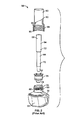
- FIG. 1 is a front elevational view of a refill for a volatile material
- FIG 2 is an exploded top isometric view of the refill of FIG. 1 with a partial cutaway of an overcap thereof to show threading in the overcap;
- FIG. 3 is a side elevational view of the refill of FIG. 1 ;
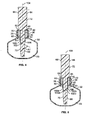
- FIG. 4 is a cross-sectional view of the refill of FIG. 1 taken generally along the lines 4-4 of FIG. 3 and with the overcap removed and incorporating a first embodiment of a retention mechanism;
- FIG. 5 is a cross-sectional view similar to FIG. 4 incorporating a second embodiment of a retention mechanism
- FIG. 6 is a cross-sectional view similar to FIG. 4 incorporating a third embodiment of a retention mechanism
- FIG. 7 is a cross-sectional view similar to FIG. 4 incorporating a fourth embodiment of a retention mechanism
- FIG. 8 is a top isometric view of a retaining ring of FIGS. 6 and 7 ;
- FIG. 9 is a plan view of the retaining ring of FIGS. 6 and 7 ;
- FIG. 10 is a cross-sectional view of the retaining ring of FIGS. 6 and 7 taken generally along the lines 10-10 of FIG. 8 .
- a refill for a volatile material 30 includes a container 32 having a volatile material disposed within a reservoir portion 33 of the container 32.
- the volatile material is preferably in liquid form and is preferably a fragrance.
- the volatile material may be an insecticide, an insect repellant, an insect attractant, a disinfectant, a sanitizer, an air purifier, an aromatherapy scent, an antiseptic, an odor eliminator, an air freshener, a deodorizer, or any other volatile material(s) that are usefully dispersed into the air.
- the container 32 is preferably, although not necessarily, made of a translucent plastic material.
- the container 32 includes an opening 34 forming a neck portion 36 of the container 32, wherein a plug assembly 38 is inserted into and secured in the neck portion 36.
- the plug assembly 38 includes an outer cylindrical wall 40 and an inner cylindrical wall 42 joined at end portions 44, 46, respectively, thereof by an annular radial planar member 50.
- An inner surface 51 of the inner cylindrical wall 42 defines a bore 52 that extends fully through the plug assembly 38.
- the plug assembly 38 is sized such that an outer surface 60 of the outer cylindrical wall 40 and an inner surface 62 of the neck portion 36 define an interference fit therebetween when the plug assembly 38 is placed into the neck portion 36 to retain the former in the latter.
- the plug assembly 38 may be retained on the neck portion 36 by a threaded connection, wherein the outer surface 60 of the outer cylindrical wall 40 and the inner surface 62 of the neck portion 36 include threads so the plug assembly 38 may be threaded into the neck portion 36.
- the plug assembly 38 may include vents (not shown) through the annular radial planar member 50 to allow air to enter and escape the reservoir portion 33 of the container 32.
- a porous wick 64 is disposed within the channel 52 such that a lower portion 66 of the wick 64 extends into the reservoir portion 33 in contact with the volatile material and an upper portion 68 of the wick 64 extends out of the container 32 and in contact with ambient air.
- the wick 64 serves to transport the volatile material in the reservoir portion 33 from the reservoir portion 33 to the upper portion 68 of the wick 64, wherein the upper portion 68 serves to disperse the volatile material into the ambient air.
- the wick 64 includes a first portion 70 having a first diameter and a second portion 72 having a second diameter, wherein the first diameter is less than the second diameter.
- the first and second diameters may be the same or the first diameter may be greater than the second diameter.
- the wick 64 is formed from a plastic material such as nylon, ultra high molecular weight high density polyethylene, or high density polypropylene.
- the first and second portions 70, 72 of the wick 64 may be formed of different materials to create portions 70, 72 with different properties. More generally, the wick 64 may have any number of portions of different or identical materials and/or dimensions and/or shapes, or a combination of different and identical materials, dimensions, and/or shapes, as desired
- the refill 30 further includes an overcap 80 that is disposed over the wick 64 when the refill 30 is not in use.
- the overcap 80 includes an upper cylindrical portion 82 and a lower cylindrical portion 84.
- an outer surface 86 of the neck portion 36 of the container 32 includes threads 88.
- An inner surface 90 of the lower cylindrical portion 84 of the overcap 80 includes corresponding threads 92 that engage the threads 88 of the neck portion 36 to allow the overcap 80 to be screwed onto the neck portion 36 of the container 32 to create a closure between the container 32 and the overcap 80.
- FIG. 4 A first embodiment of a retention mechanism of the present invention is depicted in FIG. 4 .
- the retention mechanism is implemented within the refill 30 of FIGS. 1-3 and includes a single slit 100 disposed in the lower portion 66 of the wick 64 below the plug assembly 38, wherein the slit 100 creates a barb 102.
- the barb 102 may be deformed outwardly to ensure that an interference is defined between the barb 102 and the plug assembly 38.
- the barb 102 catches on a lower portion 106 of the plug assembly 38, thereby preventing removal of the wick 64 from the plug assembly 38.
- the wick 64 may also break at an area adjacent the barb 102.
- the slit 100 is angled downwardly and inwardly at an angle and at a depth that prevents the barb 102 from breaking off due to shear forces on the barb 102 created upon an attempt to remove the wick 64 so that the barb 102 prevents removal of the wick 64.
- the slit 100 is formed at an angle A1 ( FIG. 4 ) with respect to a longitudinal axis 104 of the wick 64, wherein A1 is preferably between about 30 degrees and about 80 degrees, more preferably between about 55 degrees and about 65 degrees, and most preferably about 60 degrees.
- the slit 100 is also formed at a depth perpendicular to the longitudinal axis 104, wherein the depth is preferably between about 0.060 inch (1.52 mm) and about 0.125 inch (3.18 mm), more preferably between about 0.075 inch (1.91 mm) and about 0.085 inch (2.16 mm), and most preferably about 0.100 inch (2.54 mm).
- FIG. 5 depicts a second embodiment of a retention mechanism of the present invention.
- the retention mechanism is implemented within the refill 30 of FIGS. 1-3 and includes two slits 100a, 100b disposed in the lower portion 66 of the wick 64, below the plug assembly 38, wherein the slits 100a, 100b create corresponding barbs 102a, 102b.
- the slits 100a, 100b are disposed on diametrically opposite sides of the wick 64 opposite one another, although this need not be the case.
- one of the slits 100a, 100b may be disposed above or below the other slit 100a, 100b along the longitudinal axis 104 of the wick 64.
- any number of slits may be made in the wick 64 to form any number of barbs 102 at any locations on the wick 64, as desired, provided that the wick 64 is not unduly weakened by such slits.
- the barbs 102a, 102b catch on the lower portion 106 of the plug assembly 38, thereby preventing removal of the wick 64 from the plug assembly 38. If the pressure exerted on the wick 64 is great enough, the wick 64 may break at an area between the barbs 102a, 102b.
- the slits 100a, 100b are preferably both formed at an angle similar to the slit 100 of FIG. 4 and are preferably both formed at the same angle.
- the slits 100a, 100b may be formed at different angles within the ranges detailed above with respect to the embodiment of FIG. 4 .
- the slits 100a, 100b are formed at a depth perpendicular to the longitudinal axis 104, wherein the depth is preferably between about 0.060 inch (1.52 mm) and about 0.125 inch (3.18 mm), more preferably between about 0.075 inch (1.91 mm) and about 0.085 inch (2.16 mm), and most preferably about 0.080 inch (2.03 mm).
- FIG. 6 A third embodiment of a retention mechanism of the present invention is shown in FIG. 6 .
- the retention mechanism is employed within the refill 30 of FIGS. 1-3 .
- the retention mechanism includes a retaining ring 110 having an annular member 112 and a plurality of flexible fingers 114 integral with and extending upwardly and outwardly from the annular member 112.
- the retaining ring 110 also includes an inner annular member 116 that extends inwardly from the annular member 112 at a lower portion 118 of the annular member 112.
- the retaining ring 110 is preferably, although not necessarily, permanently secured to or integral with the inner cylindrical wall 42 of the plug assembly 38 such that a lower surface 124 of the inner cylindrical wall 42 of the plug assembly 38 is adjacent an upper surface 126 of the inner annular member 116 and an outer surface 128 of the inner cylindrical wall 42 is adjacent an inner surface 130 of the annular member 112. If the retaining ring 110 is secured to inner cylindrical wall 42, any adhesive or means for joining two components may be utilized to secure the retaining ring 110 and inner cylindrical wall 42 to one another.
- the plug assembly 38 and the retaining ring 110 are both made of a plastic material, such as for example, high density polyethylene (HDPE) or polypropylene (PP).
- the plug assembly 38 and the retaining ring 110 are preferably the same material to aid in joining the components or to aid in forming a single integral component.
- the wick 64 is inserted into the joined plug assembly 38 and retaining ring 110 and thereafter the plug assembly 38, the retaining ring 110, and the wick 64 are inserted through the neck portion 36 of the container 32.
- the flexible fingers 114 flex inwardly toward the longitudinal axis 104 of the wick 64 as the plug assembly 38, the retaining ring 110, and the wick 64 are inserted through the neck portion 36 of the container 32 and the flexible fingers 114 expand outwardly as soon as the fingers 114 pass from the neck portion 36 into the reservoir portion 33 of the container 32 (i.e., as soon as the fingers 114 clear the bore 52 of the neck portion 36).
- the fingers 114 expand outwardly such that the retaining ring 110 with expanded fingers 114 has a diameter D1 ( FIG. 10 ) that is greater than an inner diameter D2 ( FIGS. 6 and 7 ) of the bore 52 of the neck portion 36, thereby preventing removal of the plug assembly 38 and the retaining ring 110 from the container 32.
- the fingers 114 are disposed at an angle A2 from a lateral axis 115 ( FIG. 10 ) in an expanded position, wherein the lateral axis 115 is aligned with a lower edge 140 of the retaining ring 110.
- the angle A2 is between about 30 degrees and about 80 degrees, more preferably between about 45 degrees and about 55 degrees, and most preferably about 50 degrees.
- sixteen flexible fingers 114 are depicted, one or more flexible fingers 114 could be utilized to resist removal of the plug assembly 38 from the container 32 and still create balance around a circumference of the retaining ring 114.
- the finger may extend around a large portion or the entire retaining ring 114.
- FIG. 7 depicts a fourth embodiment of a retention mechanism of the present invention.
- the retention mechanism includes one or more slits 100a, 100b disposed in the wick 64 and forming corresponding barbs 102a, 102b, wherein the slit(s) 100a, 100b are discussed in detail above with respect to the first and second embodiments of FIGS. 4 and 5 .
- the retention mechanism of FIG. 7 further includes a retaining ring 110, as discussed in detail above with respect to the third embodiment of FIG. 6 .
- the barb 102 In use, if a user attempts to extract the wick 64 from the plug assembly 38, the barb 102 catches on a lower portion 106 of the plug assembly 38 and/or the retaining ring 110, thereby preventing removal of the wick 64 from the plug assembly 38.
- the retaining ring 110 prevents removal of the plug assembly 38 from the neck portion 36 of the container 32 that might occur if there is resistance to removal of the wick 64 from the plug assembly 38.
- the retention mechanisms as disclosed herein may be employed in any number of refills and may be utilized with any number of diffusion devices. Examples of some of such refills and diffusion devices are disclosed in. Schroeder et al. U.S. Patent No. 5,647,053, issued July 8, 1997 , and entitled “Vapor Dispensing Device," Greatbatch et al. U.S. Patent No. 5,909,845, issued June 8, 1999 , and entitled “Wick-based Liquid Emanation System with Child-resistant Overcap,” Pedrotti et al. U.S. Patent No. 6,862,403, issued March 1, 2005 , and entitled “Rotatable Plug Assembly Including an Extra Outlet,” Helf et al. U.S. Patent No.
- the present invention provides various features incorporated into a refill, wherein the features facilitate retention of a wick within a container.
- the wick is secured within an opening of the container by a plug assembly, wherein the container holds a volatile material in liquid form.
- the features described herein prevent removal of the wick from the plug assembly and/or prevent removal of the plug assembly through the container opening.
Abstract
Description
- Not applicable.
- The present invention relates to refills for volatile materials, and more particularly, to refills for volatile materials and retention mechanisms therefor.
- Devices that release vapors into the air are well-known in the art. Generally, the purpose of such devices is to deodorize, disinfect, or add positive fragrance to the ambient air, or to distribute insect repellants or insecticides into the air to kill or repel unwanted pests, such as mosquitoes and gnats.
- Various types of devices have been employed to dispense vapors into the air. For example, passive dispensing devices are known, wherein a volatile material in a gel, liquid, or solid form is provided within a container. The volatile material is diffused into the surrounding atmosphere, and the diffusion may be assisted by the natural airflow within the surroundings. A vent may be included in such passive dispensing devices to increase and decrease the amount of volatile material emitted from the passive dispensing devices. Aerosol containers have also been employed to eject droplets of volatile material from a pressurized container into a surrounding atmosphere upon activation of a trigger.
- Other devices have utilized mechanical or electrical devices to disperse volatile materials into the atmosphere. In one such device, a container having a porous wick disposed therein in contact with a liquid volatile material and extending out a neck of the container is disposed within a diffusion device. The volatile material travels through the porous wick to an exposed end thereof. The diffusion device may include a heater and/or a fan disposed adjacent the exposed end of the wick to assist in the volatilization and/or dispersion of the liquid volatile material in the wick.
- Containers having wicks in contact with a volatile material generally include a reservoir portion for holding the volatile material and a neck portion that forms an opening in communication with the reservoir portion. A neck closure or plug is disposed within the neck portion, wherein the neck closure includes a hole through a central portion thereof. Various devices have been utilized to secure the wick within the neck closure. One such device includes sectors formed in the neck closure with downwardly extending semi-pyramidal-shaped projections having a triangular outline, wherein the projections extend into and clamp the wick to prevent removal of the wick from the neck closure. Another device comprises a retaining pin that extends through a portion of the wick below the neck closure to prevent removal of the wick through the neck closure. In another embodiment, a cylindrical neck closure is disposed within a neck portion of the container and cylindrical portions of the retaining ring above and/or below the neck portion are crimped to form pressure points on the wick to preclude upward extraction of the wick from the neck closure. Still another device includes an annular groove formed in a lower portion of the wick and a flexible collar disposed within the annular groove. The collar includes opposing wings that help prevent removal of the wick from the container.
- According to one aspect of the present invention, a refill for a volatile material includes a container having a reservoir portion and a neck portion. The refill further includes a plug assembly disposed within the neck portion of the container and a channel through a central portion of the plug assembly. Still further the refill includes a porous wick extending through the channel, wherein the wick includes an upper portion extending outside the container and a lower portion disposed within the reservoir portion. A slit is formed in the lower portion of the wick to form a barb that catches on the plug assembly to prevent removal of the wick from the container.
- According to another aspect of the present invention, a refill for a volatile material includes a container having a reservoir portion and a neck portion. The refill further includes a plug assembly disposed within the neck portion of the container and a channel through a central portion of the plug assembly. Still further, the refill includes a porous wick extending through the channel and a retaining ring extending outwardly from a bottom portion of the plug assembly. The retaining ring includes a plurality of flexible fingers extending outwardly therefrom, wherein the flexible fingers allow insertion of the plug assembly through the neck portion of the container but prevent extraction of the plug assembly through same.
- According to yet another aspect of the present invention, a refill for a volatile material includes a container having a reservoir portion and a neck portion. The refill further includes a plug assembly disposed within the neck portion of the container and a channel through a central portion of the plug assembly. A porous wick extends through the channel, wherein the wick includes an upper portion extending outside the container and a lower portion disposed within the reservoir portion. A slit is formed in the lower portion of the wick, wherein the slit forms a barb that catches on the plug assembly to prevent removal of the wick from the container. A retaining ring extends outwardly from a bottom portion of the plug assembly, wherein the retaining ring prevents extraction of the plug assembly through the neck portion.
- Other aspects and advantages of the present invention will become apparent upon consideration of the following detailed description.
-
FIG. 1 is a front elevational view of a refill for a volatile material; -
FIG 2 is an exploded top isometric view of the refill ofFIG. 1 with a partial cutaway of an overcap thereof to show threading in the overcap; -
FIG. 3 is a side elevational view of the refill ofFIG. 1 ; -
FIG. 4 is a cross-sectional view of the refill ofFIG. 1 taken generally along the lines 4-4 ofFIG. 3 and with the overcap removed and incorporating a first embodiment of a retention mechanism; -
FIG. 5 is a cross-sectional view similar toFIG. 4 incorporating a second embodiment of a retention mechanism; -
FIG. 6 is a cross-sectional view similar toFIG. 4 incorporating a third embodiment of a retention mechanism; -
FIG. 7 is a cross-sectional view similar toFIG. 4 incorporating a fourth embodiment of a retention mechanism; -
FIG. 8 is a top isometric view of a retaining ring ofFIGS. 6 and 7 ; -
FIG. 9 is a plan view of the retaining ring ofFIGS. 6 and 7 ; and -
FIG. 10 is a cross-sectional view of the retaining ring ofFIGS. 6 and 7 taken generally along the lines 10-10 ofFIG. 8 . - Throughout the figures, like or corresponding reference numerals have been used for like or corresponding parts.
- As depicted in
FIGS. 1-3 , a refill for avolatile material 30 includes acontainer 32 having a volatile material disposed within areservoir portion 33 of thecontainer 32. The volatile material is preferably in liquid form and is preferably a fragrance. Alternatively, the volatile material may be an insecticide, an insect repellant, an insect attractant, a disinfectant, a sanitizer, an air purifier, an aromatherapy scent, an antiseptic, an odor eliminator, an air freshener, a deodorizer, or any other volatile material(s) that are usefully dispersed into the air. - The
container 32 is preferably, although not necessarily, made of a translucent plastic material. Thecontainer 32 includes anopening 34 forming aneck portion 36 of thecontainer 32, wherein aplug assembly 38 is inserted into and secured in theneck portion 36. Referring toFIGS. 4-6 , theplug assembly 38 includes an outercylindrical wall 40 and an innercylindrical wall 42 joined atend portions planar member 50. Aninner surface 51 of the innercylindrical wall 42 defines abore 52 that extends fully through theplug assembly 38. Theplug assembly 38 is sized such that anouter surface 60 of the outercylindrical wall 40 and aninner surface 62 of theneck portion 36 define an interference fit therebetween when theplug assembly 38 is placed into theneck portion 36 to retain the former in the latter. Optionally, theplug assembly 38 may be retained on theneck portion 36 by a threaded connection, wherein theouter surface 60 of the outercylindrical wall 40 and theinner surface 62 of theneck portion 36 include threads so theplug assembly 38 may be threaded into theneck portion 36. Theplug assembly 38 may include vents (not shown) through the annular radialplanar member 50 to allow air to enter and escape thereservoir portion 33 of thecontainer 32. - A
porous wick 64 is disposed within thechannel 52 such that alower portion 66 of thewick 64 extends into thereservoir portion 33 in contact with the volatile material and anupper portion 68 of thewick 64 extends out of thecontainer 32 and in contact with ambient air. Thewick 64 serves to transport the volatile material in thereservoir portion 33 from thereservoir portion 33 to theupper portion 68 of thewick 64, wherein theupper portion 68 serves to disperse the volatile material into the ambient air. - In the refill of
FIGS. 1-3 , thewick 64 includes afirst portion 70 having a first diameter and asecond portion 72 having a second diameter, wherein the first diameter is less than the second diameter. Optionally, the first and second diameters may be the same or the first diameter may be greater than the second diameter. Thewick 64 is formed from a plastic material such as nylon, ultra high molecular weight high density polyethylene, or high density polypropylene. Optionally, the first andsecond portions wick 64 may be formed of different materials to createportions wick 64 may have any number of portions of different or identical materials and/or dimensions and/or shapes, or a combination of different and identical materials, dimensions, and/or shapes, as desired - As seen in
FIGS. 1-3 , therefill 30 further includes anovercap 80 that is disposed over thewick 64 when therefill 30 is not in use. Theovercap 80 includes an uppercylindrical portion 82 and a lowercylindrical portion 84. Referring toFIG. 1 , anouter surface 86 of theneck portion 36 of thecontainer 32 includes threads 88. Aninner surface 90 of the lowercylindrical portion 84 of theovercap 80 includes correspondingthreads 92 that engage the threads 88 of theneck portion 36 to allow theovercap 80 to be screwed onto theneck portion 36 of thecontainer 32 to create a closure between thecontainer 32 and theovercap 80. - A first embodiment of a retention mechanism of the present invention is depicted in
FIG. 4 . The retention mechanism is implemented within therefill 30 ofFIGS. 1-3 and includes asingle slit 100 disposed in thelower portion 66 of thewick 64 below theplug assembly 38, wherein theslit 100 creates abarb 102. In any of the embodiments described herein, prior to or after insertion into theplug assembly 38, thebarb 102 may be deformed outwardly to ensure that an interference is defined between thebarb 102 and theplug assembly 38. In use, if a user attempts to extract thewick 64 from theplug assembly 38, thebarb 102 catches on alower portion 106 of theplug assembly 38, thereby preventing removal of thewick 64 from theplug assembly 38. If enough pressure is exerted on thewick 64, thewick 64 may also break at an area adjacent thebarb 102. Theslit 100 is angled downwardly and inwardly at an angle and at a depth that prevents thebarb 102 from breaking off due to shear forces on thebarb 102 created upon an attempt to remove thewick 64 so that thebarb 102 prevents removal of thewick 64. In particular, theslit 100 is formed at an angle A1 (FIG. 4 ) with respect to alongitudinal axis 104 of thewick 64, wherein A1 is preferably between about 30 degrees and about 80 degrees, more preferably between about 55 degrees and about 65 degrees, and most preferably about 60 degrees. Theslit 100 is also formed at a depth perpendicular to thelongitudinal axis 104, wherein the depth is preferably between about 0.060 inch (1.52 mm) and about 0.125 inch (3.18 mm), more preferably between about 0.075 inch (1.91 mm) and about 0.085 inch (2.16 mm), and most preferably about 0.100 inch (2.54 mm). -
FIG. 5 depicts a second embodiment of a retention mechanism of the present invention. The retention mechanism is implemented within therefill 30 ofFIGS. 1-3 and includes twoslits lower portion 66 of thewick 64, below theplug assembly 38, wherein theslits barbs slits wick 64 opposite one another, although this need not be the case. Optionally, one of theslits other slit longitudinal axis 104 of thewick 64. In fact, in any of the embodiments disclosed herein, any number of slits may be made in thewick 64 to form any number ofbarbs 102 at any locations on thewick 64, as desired, provided that thewick 64 is not unduly weakened by such slits. As with the embodiment ofFIG. 4 , if a user attempts to extract thewick 64 from theplug assembly 38, thebarbs lower portion 106 of theplug assembly 38, thereby preventing removal of thewick 64 from theplug assembly 38. If the pressure exerted on thewick 64 is great enough, thewick 64 may break at an area between thebarbs slits slit 100 ofFIG. 4 and are preferably both formed at the same angle. Optionally, theslits FIG. 4 . Theslits longitudinal axis 104, wherein the depth is preferably between about 0.060 inch (1.52 mm) and about 0.125 inch (3.18 mm), more preferably between about 0.075 inch (1.91 mm) and about 0.085 inch (2.16 mm), and most preferably about 0.080 inch (2.03 mm). - A third embodiment of a retention mechanism of the present invention is shown in
FIG. 6 . The retention mechanism is employed within therefill 30 ofFIGS. 1-3 . As best seen inFIGS. 8-10 , the retention mechanism includes a retainingring 110 having anannular member 112 and a plurality offlexible fingers 114 integral with and extending upwardly and outwardly from theannular member 112. The retainingring 110 also includes an innerannular member 116 that extends inwardly from theannular member 112 at alower portion 118 of theannular member 112. The retainingring 110 is preferably, although not necessarily, permanently secured to or integral with the innercylindrical wall 42 of theplug assembly 38 such that alower surface 124 of the innercylindrical wall 42 of theplug assembly 38 is adjacent anupper surface 126 of the innerannular member 116 and anouter surface 128 of the innercylindrical wall 42 is adjacent aninner surface 130 of theannular member 112. If the retainingring 110 is secured to innercylindrical wall 42, any adhesive or means for joining two components may be utilized to secure the retainingring 110 and innercylindrical wall 42 to one another. Preferably, although not necessarily, theplug assembly 38 and the retainingring 110 are both made of a plastic material, such as for example, high density polyethylene (HDPE) or polypropylene (PP). Also, theplug assembly 38 and the retainingring 110 are preferably the same material to aid in joining the components or to aid in forming a single integral component. - During assembly of the
refill 30 and the retention mechanism ofFIG. 6 , thewick 64 is inserted into the joinedplug assembly 38 and retainingring 110 and thereafter theplug assembly 38, the retainingring 110, and thewick 64 are inserted through theneck portion 36 of thecontainer 32. Theflexible fingers 114 flex inwardly toward thelongitudinal axis 104 of thewick 64 as theplug assembly 38, the retainingring 110, and thewick 64 are inserted through theneck portion 36 of thecontainer 32 and theflexible fingers 114 expand outwardly as soon as thefingers 114 pass from theneck portion 36 into thereservoir portion 33 of the container 32 (i.e., as soon as thefingers 114 clear thebore 52 of the neck portion 36). Thefingers 114 expand outwardly such that the retainingring 110 with expandedfingers 114 has a diameter D1 (FIG. 10 ) that is greater than an inner diameter D2 (FIGS. 6 and 7 ) of thebore 52 of theneck portion 36, thereby preventing removal of theplug assembly 38 and the retainingring 110 from thecontainer 32. Thefingers 114 are disposed at an angle A2 from a lateral axis 115 (FIG. 10 ) in an expanded position, wherein thelateral axis 115 is aligned with alower edge 140 of the retainingring 110. Preferably, the angle A2 is between about 30 degrees and about 80 degrees, more preferably between about 45 degrees and about 55 degrees, and most preferably about 50 degrees. - Although sixteen
flexible fingers 114 are depicted, one or moreflexible fingers 114 could be utilized to resist removal of theplug assembly 38 from thecontainer 32 and still create balance around a circumference of the retainingring 114. In an embodiment including one flexible finger, the finger may extend around a large portion or theentire retaining ring 114. -
FIG. 7 depicts a fourth embodiment of a retention mechanism of the present invention. The retention mechanism includes one ormore slits wick 64 and formingcorresponding barbs FIGS. 4 and 5 . The retention mechanism ofFIG. 7 further includes a retainingring 110, as discussed in detail above with respect to the third embodiment ofFIG. 6 . In use, if a user attempts to extract thewick 64 from theplug assembly 38, thebarb 102 catches on alower portion 106 of theplug assembly 38 and/or the retainingring 110, thereby preventing removal of thewick 64 from theplug assembly 38. The retainingring 110 prevents removal of theplug assembly 38 from theneck portion 36 of thecontainer 32 that might occur if there is resistance to removal of thewick 64 from theplug assembly 38. - The retention mechanisms as disclosed herein may be employed in any number of refills and may be utilized with any number of diffusion devices. Examples of some of such refills and diffusion devices are disclosed in.
Schroeder et al. U.S. Patent No. 5,647,053, issued July 8, 1997 , and entitled "Vapor Dispensing Device,"Greatbatch et al. U.S. Patent No. 5,909,845, issued June 8, 1999 , and entitled "Wick-based Liquid Emanation System with Child-resistant Overcap,"Pedrotti et al. U.S. Patent No. 6,862,403, issued March 1, 2005 , and entitled "Rotatable Plug Assembly Including an Extra Outlet,"Helf et al. U.S. Patent No. 6,706,988, issued March 16, 2004 , and entitled "Switch Actuating Mechanism and Electrically Controlled Device Using Same,"Martens, III et al. U.S. Patent No. 6,752,327, issued June 22, 2004 , and entitled "Atomizer with Tilted Orifice Plate and Replacement Reservoir for Same,"Schram et al. U.S. Patent No. 6,786,427, issued September 7, 2004 , and entitled "Liquid Sealing Arrangements for Replaceable Liquid Reservoirs," andMajerowski et al. U.S. Patent Application Serial No. 11/442,802, filed May 30, 2006 - The present invention provides various features incorporated into a refill, wherein the features facilitate retention of a wick within a container. Generally, the wick is secured within an opening of the container by a plug assembly, wherein the container holds a volatile material in liquid form. The features described herein prevent removal of the wick from the plug assembly and/or prevent removal of the plug assembly through the container opening.
- Numerous modifications to the present invention will be apparent to those skilled in the art in view of the foregoing description. Accordingly, this description is to be construed as illustrative only and is presented for the purpose of enabling those skilled in the art to make and use the invention and to teach the best mode of carrying out same. The exclusive rights to all modifications which come within the scope of the appended claims are reserved. Further embodiments forming part of the present disclosure are set out in the paragraphs that follow:
- Paragraph 1 A refill for a volatile material, comprising: a container having a reservoir portion and a neck portion; a plug assembly disposed within the neck portion of the container and further including a channel through a central portion of the plug assembly; a porous wick extending through the channel, wherein the wick includes an upper portion extending outside the container and a lower portion disposed within the reservoir portion; and a slit formed in the lower portion of the wick to form a barb that catches on the plug assembly to prevent removal of the wick from the container.
- Paragraph 2 The refill of paragraph 1, wherein the slit is formed in the wick at a downward angle.
- Paragraph 3 The refill of paragraph 2, wherein the slit is formed at an angle of about 60 degrees with respect to a longitudinal axis of the wick to allow the barb to catch on the plug assembly.
-
Paragraph 4 The refill of paragraph 1, wherein a second slit is formed in the lower portion of the wick to form a second barb that catches on the plug assembly to prevent removal of the wick from the container. - Paragraph 5 The refill of
paragraph 4, wherein the first-named and second slits are disposed on diametrically opposite sides of the wick.
Claims (15)
- A refill for a volatile material (32), comprising:a container (32) having a reservoir portion (33) and a neck portion (36);a plug assembly (38) disposed within the neck portion (36)of the container (32) and further including a channel (52) through a central portion of the plug assembly (38);a porous wick (64) extending through the channel (52); anda retaining ring (110) extending outwardly from a bottom portion of the plug assembly (38), wherein the retaining ring (110) includes at least one flexible finger (114) extending outwardly therefrom and wherein the flexible finger (114) allows insertion of the plug assembly (38) through the neck portion (36) but prevents extraction of the plug assembly (38) through the neck portion (36).
- The refill of claim 1, wherein the at least one flexible finger (114) extends outwardly and upwardly toward a top portion of the container (32).
- The refill of claim 2, wherein the at least one flexible finger (114) extends outwardly and upwardly at an angle of about 50 degrees from a lateral axis aligned with a lower edge of the retaining ring.
- The refill of any of claims 1-3, wherein the at least one flexible finger (114) comprises a plurality of flexible fingers (114).
- The refill of claim 4, wherein the at least one flexible finger (114) comprises twelve fingers fingers.
- The refill of any of claims 1-5, wherein the wick (64) has a slit formed at a downward angle of about 60 degrees with respect to a longitudinal axis of the wick to form a barb that catches on the plug assembly to prevent removal of the wick (64) from the container (32).
- The refill of any of claims 1-6, wherein the retaining ring (110) is secured to the plug assembly (38).
- The refill of claim 7, wherein the retaining ring (110) is integral with the plug assembly (38).
- A refill for a volatile material (32), comprising:a container (32) having a reservoir portion (33) and a neck portion (36);a plug assembly (38) disposed within the neck portion (36) of the container (32) and further including a channel (52) through a central portion of the plug assembly (38);a porous wick (64) extending through the channel (58), wherein the wick (64) includes an upper portion extending outside the container (32) and a lower portion (66) disposed within the reservoir portion (33);a slit (100) formed in the lower portion (66) of the wick (64), wherein the slit (100) forms a barb (102) that catches on the plug assembly (38) to prevent removal of the wick (64) from the container (32); anda retaining ring (110) extending outwardly from a bottom portion of the plug assembly (38), wherein the retaining ring (110) prevents extraction of the plug assembly (38) through the neck portion (36).
- The refill of claim 9, wherein the retaining ring includes a plurality of flexible fingers (114) extending outwardly therefrom and wherein the flexible fingers (114) allow insertion of the plug assembly (38) through the neck portion (36) but prevent extraction of the plug assembly (38) through the neck portion (36).
- The refill of claims 9 or 10, wherein the slit is formed at a downward angle of about 60 degrees with respect to a longitudinal axis of the wick to allow the barb to catch on the retaining ring.
- The refill of any of claims 9-11, further including a second slit (100b) formed in the wick (64) at a downward angle, wherein the first-named and second slits (100a, 100b) are disposed in diametrically opposite sides of the wick (64).
- The refill of claim 10, wherein the flexible fingers (114) extend outwardly and upwardly toward a top portion of the container (32) at an angle of about 50 degrees from a lateral axis aligned with a lower edge of the retaining ring (110).
- The refill of any of claims 9-13, wherein the retaining ring (110) is secured to the plug assembly (38).
- The refill of claim 14, wherein the retaining ring (110) is integral with the plug assembly (38).
Applications Claiming Priority (2)
| Application Number | Priority Date | Filing Date | Title |
|---|---|---|---|
| US11/522,641 US7628338B2 (en) | 2006-09-18 | 2006-09-18 | Refill for a volatile material |
| EP07838407A EP2068945B1 (en) | 2006-09-18 | 2007-09-18 | Refill for a volatile material |
Related Parent Applications (1)
| Application Number | Title | Priority Date | Filing Date |
|---|---|---|---|
| EP07838407.0 Division | 2007-09-18 |
Publications (2)
| Publication Number | Publication Date |
|---|---|
| EP2238989A1 true EP2238989A1 (en) | 2010-10-13 |
| EP2238989B1 EP2238989B1 (en) | 2011-12-07 |
Family
ID=38920492
Family Applications (2)
| Application Number | Title | Priority Date | Filing Date |
|---|---|---|---|
| EP07838407A Not-in-force EP2068945B1 (en) | 2006-09-18 | 2007-09-18 | Refill for a volatile material |
| EP10170385A Not-in-force EP2238989B1 (en) | 2006-09-18 | 2007-09-18 | Refill for a volatile material |
Family Applications Before (1)
| Application Number | Title | Priority Date | Filing Date |
|---|---|---|---|
| EP07838407A Not-in-force EP2068945B1 (en) | 2006-09-18 | 2007-09-18 | Refill for a volatile material |
Country Status (9)
| Country | Link |
|---|---|
| US (1) | US7628338B2 (en) |
| EP (2) | EP2068945B1 (en) |
| CN (1) | CN101516410B (en) |
| AT (2) | ATE536191T1 (en) |
| AU (1) | AU2007297745A1 (en) |
| DE (1) | DE602007012909D1 (en) |
| ES (1) | ES2378509T3 (en) |
| MX (1) | MX2009002851A (en) |
| WO (1) | WO2008036263A2 (en) |
Families Citing this family (21)
| Publication number | Priority date | Publication date | Assignee | Title |
|---|---|---|---|---|
| US20090101730A1 (en) * | 2007-10-19 | 2009-04-23 | Davis Brian T | Vented Dispensing Bottle/Cap Assembly |
| US20090261179A1 (en) * | 2008-04-16 | 2009-10-22 | Ashland Licensing And Intellectual Property Llc | Bottle cap seal for wicked air freshener |
| US7997508B2 (en) | 2008-08-15 | 2011-08-16 | Le Cherche Midi | Spill-proof aerator for low volatile compound solutions |
| USD666705S1 (en) * | 2010-09-09 | 2012-09-04 | S.C. Johnson & Son, Inc. | Wick |
| GB2492154B (en) * | 2011-06-24 | 2016-02-17 | Reckitt & Colman Overseas | Devices and methods for emanating liquids |
| CN106455534B (en) | 2014-05-12 | 2019-12-10 | 约翰逊父子公司 | Volatile material dispenser with atomizer and atomizer assembly |
| CN111315416A (en) * | 2017-09-08 | 2020-06-19 | 宝洁公司 | Device and method for delivering volatile materials |
| WO2020023129A2 (en) * | 2018-07-25 | 2020-01-30 | S. C. Johnson & Son, Inc. | Refill for holding volatile materials |
| US10258710B1 (en) * | 2017-09-22 | 2019-04-16 | S. C. Johnson & Son, Inc. | Container for holding volatile materials |
| USD846725S1 (en) | 2017-10-23 | 2019-04-23 | S. C. Johnson & Son, Inc. | Dispenser |
| USD846724S1 (en) | 2017-10-23 | 2019-04-23 | S. C. Johnson & Son, Inc. | Dispenser |
| USD859163S1 (en) | 2017-10-23 | 2019-09-10 | S. C. Johnson & Son, Inc. | Container with cover |
| USD871226S1 (en) | 2017-10-23 | 2019-12-31 | S. C. Johnson & Son, Inc. | Container |
| ES2718118A1 (en) * | 2017-12-27 | 2019-06-27 | Zobele Espana Sa | Support for volatile substances diffusion wicks (Machine-translation by Google Translate, not legally binding) |
| USD872245S1 (en) | 2018-02-28 | 2020-01-07 | S. C. Johnson & Son, Inc. | Dispenser |
| USD880670S1 (en) | 2018-02-28 | 2020-04-07 | S. C. Johnson & Son, Inc. | Overcap |
| USD872847S1 (en) | 2018-02-28 | 2020-01-14 | S. C. Johnson & Son, Inc. | Dispenser |
| USD881365S1 (en) | 2018-02-28 | 2020-04-14 | S. C. Johnson & Son, Inc. | Dispenser |
| USD852938S1 (en) | 2018-05-07 | 2019-07-02 | S. C. Johnson & Son, Inc. | Dispenser |
| USD853548S1 (en) | 2018-05-07 | 2019-07-09 | S. C. Johnson & Son, Inc. | Dispenser |
| ES2836874A1 (en) * | 2019-12-27 | 2021-06-28 | Zobele Espana Sa | Volatile substance diffusion device (Machine-translation by Google Translate, not legally binding) |
Citations (11)
| Publication number | Priority date | Publication date | Assignee | Title |
|---|---|---|---|---|
| US4621768A (en) * | 1984-10-09 | 1986-11-11 | Reckitt & Colman S.A. | Device for diffusing volatile liquids |
| US5647053A (en) | 1995-10-11 | 1997-07-08 | S. C. Johnson & Son, Inc. | Vapor dipensing device |
| US5909845A (en) | 1996-06-28 | 1999-06-08 | S. C. Johnson & Son, Inc. | Wick-based liquid emanation system with child-resistant overcap |
| EP1103479A1 (en) * | 1999-02-15 | 2001-05-30 | DBK Espana, S.A. | Plug for receptacles containing evaporable liquids |
| US6446880B1 (en) * | 2000-08-02 | 2002-09-10 | S.C. Johnson & Son, Inc. | Replaceable reservoir for an atomizing apparatus |
| US6706988B1 (en) | 2002-11-08 | 2004-03-16 | S. C. Johnson & Son, Inc. | Switch actuating mechanism and electrically controlled device using same |
| US6752327B2 (en) | 2002-10-16 | 2004-06-22 | S. C. Johnson & Son, Inc. | Atomizer with tilted orifice plate and replacement reservoir for same |
| US6786427B2 (en) | 2002-12-19 | 2004-09-07 | S. C. Johnson & Son, Inc. | Liquid sealing arrangements for replaceable liquid reservoirs |
| US6862403B2 (en) | 2001-08-07 | 2005-03-01 | S.C. Johnson & Son, Inc. | Rotatable plug assembly including an extra outlet |
| US20060016904A1 (en) * | 2003-06-12 | 2006-01-26 | Zobele Espana, S.A. | Adjustable non-electric liquid air freshener device |
| US20060163376A1 (en) * | 2002-10-08 | 2006-07-27 | Lakatos Kara L | Breakable wick for use in a dispenser for a volatile liquid |
Family Cites Families (12)
| Publication number | Priority date | Publication date | Assignee | Title |
|---|---|---|---|---|
| US2474607A (en) * | 1946-06-13 | 1949-06-28 | Airkem Inc | Liquid diffuser |
| US2474605A (en) * | 1948-10-26 | 1949-06-28 | Airkem Inc | Liquid diffuser |
| US3089182A (en) * | 1960-02-11 | 1963-05-14 | Sanford Corp Of Liberia | Marking device |
| US3091396A (en) * | 1961-09-20 | 1963-05-28 | Vanderburgh County Soc For Cri | Wick assembly |
| US3345674A (en) * | 1964-10-02 | 1967-10-10 | Sanford Res Company | Marking device |
| FR2761959B1 (en) * | 1997-04-15 | 1999-05-21 | Oreal | PACKAGING AND APPLICATION ASSEMBLY OF A FLUID PRODUCT |
| US6236807B1 (en) * | 2000-01-07 | 2001-05-22 | Bath & Body Works, Inc. | Wick-based liquid emanation system with child-resistant and miniaturization features |
| WO2002031413A2 (en) * | 2000-10-09 | 2002-04-18 | The Dial Corporation | Method and apparatus for fastening a fluid transport mechanism to a container |
| US6896196B2 (en) * | 2002-01-16 | 2005-05-24 | C.T.R. Consultoria Tecnica E Representacoes Lda | Evaporative container for volatile substances |
| US6619560B1 (en) * | 2002-07-19 | 2003-09-16 | Blyth, Inc. | Bottle assembly with wick holder assembly |
| US20040262419A1 (en) * | 2003-06-27 | 2004-12-30 | Kotary Kara L. | Breakable wick for use in a dispenser for a volatile liquid |
| US6899280B2 (en) * | 2002-10-08 | 2005-05-31 | S. C. Johnson & Son, Inc. | Wick-based delivery system with wick having sections of varying porosities |
-
2006
- 2006-09-18 US US11/522,641 patent/US7628338B2/en not_active Expired - Fee Related
-
2007
- 2007-09-18 CN CN200780034664.8A patent/CN101516410B/en not_active Expired - Fee Related
- 2007-09-18 WO PCT/US2007/020190 patent/WO2008036263A2/en active Application Filing
- 2007-09-18 MX MX2009002851A patent/MX2009002851A/en not_active Application Discontinuation
- 2007-09-18 AT AT10170385T patent/ATE536191T1/en active
- 2007-09-18 EP EP07838407A patent/EP2068945B1/en not_active Not-in-force
- 2007-09-18 DE DE602007012909T patent/DE602007012909D1/en active Active
- 2007-09-18 AT AT07838407T patent/ATE499952T1/en not_active IP Right Cessation
- 2007-09-18 EP EP10170385A patent/EP2238989B1/en not_active Not-in-force
- 2007-09-18 AU AU2007297745A patent/AU2007297745A1/en not_active Abandoned
- 2007-09-18 ES ES10170385T patent/ES2378509T3/en active Active
Patent Citations (11)
| Publication number | Priority date | Publication date | Assignee | Title |
|---|---|---|---|---|
| US4621768A (en) * | 1984-10-09 | 1986-11-11 | Reckitt & Colman S.A. | Device for diffusing volatile liquids |
| US5647053A (en) | 1995-10-11 | 1997-07-08 | S. C. Johnson & Son, Inc. | Vapor dipensing device |
| US5909845A (en) | 1996-06-28 | 1999-06-08 | S. C. Johnson & Son, Inc. | Wick-based liquid emanation system with child-resistant overcap |
| EP1103479A1 (en) * | 1999-02-15 | 2001-05-30 | DBK Espana, S.A. | Plug for receptacles containing evaporable liquids |
| US6446880B1 (en) * | 2000-08-02 | 2002-09-10 | S.C. Johnson & Son, Inc. | Replaceable reservoir for an atomizing apparatus |
| US6862403B2 (en) | 2001-08-07 | 2005-03-01 | S.C. Johnson & Son, Inc. | Rotatable plug assembly including an extra outlet |
| US20060163376A1 (en) * | 2002-10-08 | 2006-07-27 | Lakatos Kara L | Breakable wick for use in a dispenser for a volatile liquid |
| US6752327B2 (en) | 2002-10-16 | 2004-06-22 | S. C. Johnson & Son, Inc. | Atomizer with tilted orifice plate and replacement reservoir for same |
| US6706988B1 (en) | 2002-11-08 | 2004-03-16 | S. C. Johnson & Son, Inc. | Switch actuating mechanism and electrically controlled device using same |
| US6786427B2 (en) | 2002-12-19 | 2004-09-07 | S. C. Johnson & Son, Inc. | Liquid sealing arrangements for replaceable liquid reservoirs |
| US20060016904A1 (en) * | 2003-06-12 | 2006-01-26 | Zobele Espana, S.A. | Adjustable non-electric liquid air freshener device |
Also Published As
| Publication number | Publication date |
|---|---|
| WO2008036263A3 (en) | 2008-08-21 |
| CN101516410A (en) | 2009-08-26 |
| EP2068945B1 (en) | 2011-03-02 |
| US20080093475A1 (en) | 2008-04-24 |
| AU2007297745A1 (en) | 2008-03-27 |
| DE602007012909D1 (en) | 2011-04-14 |
| ES2378509T3 (en) | 2012-04-13 |
| ATE499952T1 (en) | 2011-03-15 |
| EP2068945A2 (en) | 2009-06-17 |
| EP2238989B1 (en) | 2011-12-07 |
| WO2008036263A2 (en) | 2008-03-27 |
| MX2009002851A (en) | 2009-03-27 |
| CN101516410B (en) | 2014-01-15 |
| ATE536191T1 (en) | 2011-12-15 |
| US7628338B2 (en) | 2009-12-08 |
Similar Documents
| Publication | Publication Date | Title |
|---|---|---|
| EP2238989B1 (en) | Refill for a volatile material | |
| AU2003275010B9 (en) | Wick-based delivery system with wick having sections of varying porosities | |
| US8657139B1 (en) | System for delivering deodorizer and repellent for a container | |
| AU2008219204B2 (en) | Active material diffuser and method of providing and using same | |
| EP2931321B1 (en) | Refill | |
| CA2574872A1 (en) | Vapor dispersing device and method | |
| WO1999003514A1 (en) | Liquid air freshener dispenser device with nonporous capillary wicking function | |
| EP1558298B1 (en) | Device for diffusing volatile substances to ambient air comprising a wick with predetermined porosity | |
| US20150083755A1 (en) | Dispensing System with Bracket | |
| US20140161428A1 (en) | Devices And Methods For Emanating Liquids | |
| US20150135503A1 (en) | Method of attaching two or more different refills to a volatile material dispenser | |
| KR20150100918A (en) | Activating a volatile reservoir using a lateral force | |
| WO2003101499A1 (en) | Passive vapor-dispensing device | |
| US20200114036A1 (en) | Liquid air freshener and delivery system |
Legal Events
| Date | Code | Title | Description |
|---|---|---|---|
| PUAI | Public reference made under article 153(3) epc to a published international application that has entered the european phase |
Free format text: ORIGINAL CODE: 0009012 |
|
| 17P | Request for examination filed |
Effective date: 20100722 |
|
| AC | Divisional application: reference to earlier application |
Ref document number: 2068945 Country of ref document: EP Kind code of ref document: P |
|
| AK | Designated contracting states |
Kind code of ref document: A1 Designated state(s): AT BE BG CH CY CZ DE DK EE ES FI FR GB GR HU IE IS IT LI LT LU LV MC MT NL PL PT RO SE SI SK TR |
|
| GRAP | Despatch of communication of intention to grant a patent |
Free format text: ORIGINAL CODE: EPIDOSNIGR1 |
|
| RIC1 | Information provided on ipc code assigned before grant |
Ipc: A01M 1/20 20060101ALI20110511BHEP Ipc: A61L 9/12 20060101AFI20110511BHEP |
|
| GRAS | Grant fee paid |
Free format text: ORIGINAL CODE: EPIDOSNIGR3 |
|
| GRAA | (expected) grant |
Free format text: ORIGINAL CODE: 0009210 |
|
| AC | Divisional application: reference to earlier application |
Ref document number: 2068945 Country of ref document: EP Kind code of ref document: P |
|
| AK | Designated contracting states |
Kind code of ref document: B1 Designated state(s): AT BE BG CH CY CZ DE DK EE ES FI FR GB GR HU IE IS IT LI LT LU LV MC MT NL PL PT RO SE SI SK TR |
|
| REG | Reference to a national code |
Ref country code: GB Ref legal event code: FG4D |
|
| REG | Reference to a national code |
Ref country code: CH Ref legal event code: EP |
|
| REG | Reference to a national code |
Ref country code: IE Ref legal event code: FG4D |
|
| REG | Reference to a national code |
Ref country code: DE Ref legal event code: R096 Ref document number: 602007019256 Country of ref document: DE Effective date: 20120202 |
|
| REG | Reference to a national code |
Ref country code: NL Ref legal event code: VDEP Effective date: 20111207 |
|
| REG | Reference to a national code |
Ref country code: ES Ref legal event code: FG2A Ref document number: 2378509 Country of ref document: ES Kind code of ref document: T3 Effective date: 20120413 |
|
| PG25 | Lapsed in a contracting state [announced via postgrant information from national office to epo] |
Ref country code: LT Free format text: LAPSE BECAUSE OF FAILURE TO SUBMIT A TRANSLATION OF THE DESCRIPTION OR TO PAY THE FEE WITHIN THE PRESCRIBED TIME-LIMIT Effective date: 20111207 |
|
| LTIE | Lt: invalidation of european patent or patent extension |
Effective date: 20111207 |
|
| PG25 | Lapsed in a contracting state [announced via postgrant information from national office to epo] |
Ref country code: GR Free format text: LAPSE BECAUSE OF FAILURE TO SUBMIT A TRANSLATION OF THE DESCRIPTION OR TO PAY THE FEE WITHIN THE PRESCRIBED TIME-LIMIT Effective date: 20120308 Ref country code: LV Free format text: LAPSE BECAUSE OF FAILURE TO SUBMIT A TRANSLATION OF THE DESCRIPTION OR TO PAY THE FEE WITHIN THE PRESCRIBED TIME-LIMIT Effective date: 20111207 Ref country code: SI Free format text: LAPSE BECAUSE OF FAILURE TO SUBMIT A TRANSLATION OF THE DESCRIPTION OR TO PAY THE FEE WITHIN THE PRESCRIBED TIME-LIMIT Effective date: 20111207 Ref country code: SE Free format text: LAPSE BECAUSE OF FAILURE TO SUBMIT A TRANSLATION OF THE DESCRIPTION OR TO PAY THE FEE WITHIN THE PRESCRIBED TIME-LIMIT Effective date: 20111207 Ref country code: NL Free format text: LAPSE BECAUSE OF FAILURE TO SUBMIT A TRANSLATION OF THE DESCRIPTION OR TO PAY THE FEE WITHIN THE PRESCRIBED TIME-LIMIT Effective date: 20111207 |
|
| PG25 | Lapsed in a contracting state [announced via postgrant information from national office to epo] |
Ref country code: BE Free format text: LAPSE BECAUSE OF FAILURE TO SUBMIT A TRANSLATION OF THE DESCRIPTION OR TO PAY THE FEE WITHIN THE PRESCRIBED TIME-LIMIT Effective date: 20111207 Ref country code: CY Free format text: LAPSE BECAUSE OF FAILURE TO SUBMIT A TRANSLATION OF THE DESCRIPTION OR TO PAY THE FEE WITHIN THE PRESCRIBED TIME-LIMIT Effective date: 20111207 |
|
| PG25 | Lapsed in a contracting state [announced via postgrant information from national office to epo] |
Ref country code: SK Free format text: LAPSE BECAUSE OF FAILURE TO SUBMIT A TRANSLATION OF THE DESCRIPTION OR TO PAY THE FEE WITHIN THE PRESCRIBED TIME-LIMIT Effective date: 20111207 Ref country code: EE Free format text: LAPSE BECAUSE OF FAILURE TO SUBMIT A TRANSLATION OF THE DESCRIPTION OR TO PAY THE FEE WITHIN THE PRESCRIBED TIME-LIMIT Effective date: 20111207 Ref country code: CZ Free format text: LAPSE BECAUSE OF FAILURE TO SUBMIT A TRANSLATION OF THE DESCRIPTION OR TO PAY THE FEE WITHIN THE PRESCRIBED TIME-LIMIT Effective date: 20111207 Ref country code: BG Free format text: LAPSE BECAUSE OF FAILURE TO SUBMIT A TRANSLATION OF THE DESCRIPTION OR TO PAY THE FEE WITHIN THE PRESCRIBED TIME-LIMIT Effective date: 20120307 Ref country code: IS Free format text: LAPSE BECAUSE OF FAILURE TO SUBMIT A TRANSLATION OF THE DESCRIPTION OR TO PAY THE FEE WITHIN THE PRESCRIBED TIME-LIMIT Effective date: 20120407 |
|
| PG25 | Lapsed in a contracting state [announced via postgrant information from national office to epo] |
Ref country code: PT Free format text: LAPSE BECAUSE OF FAILURE TO SUBMIT A TRANSLATION OF THE DESCRIPTION OR TO PAY THE FEE WITHIN THE PRESCRIBED TIME-LIMIT Effective date: 20120409 Ref country code: PL Free format text: LAPSE BECAUSE OF FAILURE TO SUBMIT A TRANSLATION OF THE DESCRIPTION OR TO PAY THE FEE WITHIN THE PRESCRIBED TIME-LIMIT Effective date: 20111207 Ref country code: RO Free format text: LAPSE BECAUSE OF FAILURE TO SUBMIT A TRANSLATION OF THE DESCRIPTION OR TO PAY THE FEE WITHIN THE PRESCRIBED TIME-LIMIT Effective date: 20111207 |
|
| REG | Reference to a national code |
Ref country code: AT Ref legal event code: MK05 Ref document number: 536191 Country of ref document: AT Kind code of ref document: T Effective date: 20111207 |
|
| PLBE | No opposition filed within time limit |
Free format text: ORIGINAL CODE: 0009261 |
|
| STAA | Information on the status of an ep patent application or granted ep patent |
Free format text: STATUS: NO OPPOSITION FILED WITHIN TIME LIMIT |
|
| PG25 | Lapsed in a contracting state [announced via postgrant information from national office to epo] |
Ref country code: DK Free format text: LAPSE BECAUSE OF FAILURE TO SUBMIT A TRANSLATION OF THE DESCRIPTION OR TO PAY THE FEE WITHIN THE PRESCRIBED TIME-LIMIT Effective date: 20111207 |
|
| 26N | No opposition filed |
Effective date: 20120910 |
|
| REG | Reference to a national code |
Ref country code: DE Ref legal event code: R097 Ref document number: 602007019256 Country of ref document: DE Effective date: 20120910 |
|
| PG25 | Lapsed in a contracting state [announced via postgrant information from national office to epo] |
Ref country code: AT Free format text: LAPSE BECAUSE OF FAILURE TO SUBMIT A TRANSLATION OF THE DESCRIPTION OR TO PAY THE FEE WITHIN THE PRESCRIBED TIME-LIMIT Effective date: 20111207 |
|
| PG25 | Lapsed in a contracting state [announced via postgrant information from national office to epo] |
Ref country code: MC Free format text: LAPSE BECAUSE OF NON-PAYMENT OF DUE FEES Effective date: 20120930 |
|
| REG | Reference to a national code |
Ref country code: CH Ref legal event code: PL |
|
| REG | Reference to a national code |
Ref country code: IE Ref legal event code: MM4A |
|
| PG25 | Lapsed in a contracting state [announced via postgrant information from national office to epo] |
Ref country code: FI Free format text: LAPSE BECAUSE OF FAILURE TO SUBMIT A TRANSLATION OF THE DESCRIPTION OR TO PAY THE FEE WITHIN THE PRESCRIBED TIME-LIMIT Effective date: 20111207 |
|
| REG | Reference to a national code |
Ref country code: FR Ref legal event code: ST Effective date: 20130531 |
|
| PG25 | Lapsed in a contracting state [announced via postgrant information from national office to epo] |
Ref country code: DE Free format text: LAPSE BECAUSE OF NON-PAYMENT OF DUE FEES Effective date: 20130403 Ref country code: LI Free format text: LAPSE BECAUSE OF NON-PAYMENT OF DUE FEES Effective date: 20120930 Ref country code: CH Free format text: LAPSE BECAUSE OF NON-PAYMENT OF DUE FEES Effective date: 20120930 Ref country code: IE Free format text: LAPSE BECAUSE OF NON-PAYMENT OF DUE FEES Effective date: 20120918 |
|
| PG25 | Lapsed in a contracting state [announced via postgrant information from national office to epo] |
Ref country code: FR Free format text: LAPSE BECAUSE OF NON-PAYMENT OF DUE FEES Effective date: 20121001 |
|
| REG | Reference to a national code |
Ref country code: DE Ref legal event code: R119 Ref document number: 602007019256 Country of ref document: DE Effective date: 20130403 |
|
| PG25 | Lapsed in a contracting state [announced via postgrant information from national office to epo] |
Ref country code: MT Free format text: LAPSE BECAUSE OF FAILURE TO SUBMIT A TRANSLATION OF THE DESCRIPTION OR TO PAY THE FEE WITHIN THE PRESCRIBED TIME-LIMIT Effective date: 20111207 |
|
| PG25 | Lapsed in a contracting state [announced via postgrant information from national office to epo] |
Ref country code: TR Free format text: LAPSE BECAUSE OF FAILURE TO SUBMIT A TRANSLATION OF THE DESCRIPTION OR TO PAY THE FEE WITHIN THE PRESCRIBED TIME-LIMIT Effective date: 20111207 |
|
| PG25 | Lapsed in a contracting state [announced via postgrant information from national office to epo] |
Ref country code: LU Free format text: LAPSE BECAUSE OF NON-PAYMENT OF DUE FEES Effective date: 20120918 |
|
| PG25 | Lapsed in a contracting state [announced via postgrant information from national office to epo] |
Ref country code: HU Free format text: LAPSE BECAUSE OF FAILURE TO SUBMIT A TRANSLATION OF THE DESCRIPTION OR TO PAY THE FEE WITHIN THE PRESCRIBED TIME-LIMIT Effective date: 20070918 |
|
| PGFP | Annual fee paid to national office [announced via postgrant information from national office to epo] |
Ref country code: GB Payment date: 20200819 Year of fee payment: 14 |
|
| PGFP | Annual fee paid to national office [announced via postgrant information from national office to epo] |
Ref country code: IT Payment date: 20200824 Year of fee payment: 14 |
|
| PGFP | Annual fee paid to national office [announced via postgrant information from national office to epo] |
Ref country code: ES Payment date: 20201001 Year of fee payment: 14 |
|
| GBPC | Gb: european patent ceased through non-payment of renewal fee |
Effective date: 20210918 |
|
| PG25 | Lapsed in a contracting state [announced via postgrant information from national office to epo] |
Ref country code: GB Free format text: LAPSE BECAUSE OF NON-PAYMENT OF DUE FEES Effective date: 20210918 |
|
| PG25 | Lapsed in a contracting state [announced via postgrant information from national office to epo] |
Ref country code: IT Free format text: LAPSE BECAUSE OF NON-PAYMENT OF DUE FEES Effective date: 20210918 |
|
| REG | Reference to a national code |
Ref country code: ES Ref legal event code: FD2A Effective date: 20221102 |
|
| PG25 | Lapsed in a contracting state [announced via postgrant information from national office to epo] |
Ref country code: ES Free format text: LAPSE BECAUSE OF NON-PAYMENT OF DUE FEES Effective date: 20210919 |