EP2239997A1 - Power control circuit and method - Google Patents
Power control circuit and method Download PDFInfo
- Publication number
- EP2239997A1 EP2239997A1 EP10159471A EP10159471A EP2239997A1 EP 2239997 A1 EP2239997 A1 EP 2239997A1 EP 10159471 A EP10159471 A EP 10159471A EP 10159471 A EP10159471 A EP 10159471A EP 2239997 A1 EP2239997 A1 EP 2239997A1
- Authority
- EP
- European Patent Office
- Prior art keywords
- voltage
- power
- current
- led
- light
- Prior art date
- Legal status (The legal status is an assumption and is not a legal conclusion. Google has not performed a legal analysis and makes no representation as to the accuracy of the status listed.)
- Granted
Links
Images


Classifications
-
- H—ELECTRICITY
- H05—ELECTRIC TECHNIQUES NOT OTHERWISE PROVIDED FOR
- H05B—ELECTRIC HEATING; ELECTRIC LIGHT SOURCES NOT OTHERWISE PROVIDED FOR; CIRCUIT ARRANGEMENTS FOR ELECTRIC LIGHT SOURCES, IN GENERAL
- H05B45/00—Circuit arrangements for operating light-emitting diodes [LED]
- H05B45/10—Controlling the intensity of the light
- H05B45/14—Controlling the intensity of the light using electrical feedback from LEDs or from LED modules
-
- H—ELECTRICITY
- H05—ELECTRIC TECHNIQUES NOT OTHERWISE PROVIDED FOR
- H05B—ELECTRIC HEATING; ELECTRIC LIGHT SOURCES NOT OTHERWISE PROVIDED FOR; CIRCUIT ARRANGEMENTS FOR ELECTRIC LIGHT SOURCES, IN GENERAL
- H05B45/00—Circuit arrangements for operating light-emitting diodes [LED]
- H05B45/10—Controlling the intensity of the light
- H05B45/18—Controlling the intensity of the light using temperature feedback
Definitions
- the present invention relates to a power control circuit for providing a substantially constant intensity light source and a corresponding method using this control circuit.
- traffic signal lamps typically use either incandescent or LED (light-emitting diode) lamps.
- LED traffic signals are more reliable, more mechanically stable, safer, more energy efficient and more environmentally friendly than incandescent lamps.
- LED traffic signals are gaining in popularity.
- the voltage and current characteristics of an LED lamp are sensitive to temperature.
- the LEDs used will have a forward voltage specified at an intended operating current.
- the forward voltage changes with the temperature, and, consequently, the current follows the variation.
- the forward voltage increases, then the forward current will decrease.
- the forward voltage decreases, then the forward current increases.
- a constant voltage of 1.8 volts will produce in the LED a current of about 7.5 mA at a temperature of -25° C, a current of about 20.5 mA at a temperature of +25° C, and a current of about 30 mA at a temperature of +60° C.
- the magnitude of the current through the light-emitting diode at a temperature of +60° C is therefore, for a constant voltage of 1.8 volt, about 1.6 times higher than the magnitude of the current at a temperature of +25° C.
- a constant voltage may be maintained such that the voltage across the LEDs is constant for all environments (e.g., -40 to 74 °C). It is known that at high temperatures the forward voltage of the LEDs decreases, and because the driver or the power supply maintains the voltage across the LEDs constant, the LED current will increase exponentially and stress the LEDs (bright LEDs).
- a fixed LED output current presents the following drawbacks: at higher temperature the LED forward voltage decreases and then the output LED power decreases, which means light out decreases; and at lower temperatures the LED forward voltage increases and then the output LED power increases, which means light out increases.
- a light source includes a controllable power source for supplying power to a non-linear light-emitting load; a current sensing circuit connected to the non-linear light-emitting load that generates a current signal representing the current flowing through the non-linear light-emitting load; a voltage sensing circuit connected to the non-linear light-emitting load that generates a voltage signal representing the voltage across the non-linear light-emitting load; a power sensing circuit connected to the current and voltage sensing circuits that receives the current and voltage signals and measures the power consumption of the light-emitting load and generates a variable power-representative signal; and a power feedback control circuit connected between the power sensing circuit and the controllable power source through which the power source is controlled in relation to the variable power-representative signal to maintain the power consumption of the light source substantially constant.
- a method of maintaining the intensity and power consumption of a light source substantially constant includes supplying a controllable dc voltage and current to a non-linear light-emitting load; multiplying an output forward voltage and a variable current-representative signal from the light-emitting load to generate a variable power-representative signal; and feedback controlling the controllable dc voltage and current in relation to the variable power-representative signal to keep the light intensity produced by the light source substantially constant.
- a substantially constant intensity LED lamp includes a controllable dc voltage and current source for supplying an LED load with dc voltage and current; a current sensing circuit connected with the LED load that generates a current signal representing the current flowing through the LED load; a voltage sensing circuit connected with the LED load that generates a voltage signal representing the voltage across the LED load; a multiplier circuit that receives the current signal and the voltage signal and generates a variable-power representative signal; and a voltage and current control feedback circuit connected between the power sense circuit and the controllable dc voltage and current source that receives the variable-power representative signal and controls the dc voltage and current source in relation to the variable power-representative signal to thereby adjust the dc voltage and current to keep the light intensity and power consumption produced by the LED load substantially constant.
- the power consumption of the light-emitting load varies as a result of at least one of an environmental condition of operation, manufacturer forward voltage binning batch and age of the light-emitting load
- the voltage sensing circuit produces a voltage representative signal, the voltage varying with the temperature, binning batch and aging of the light-emitting load.
- the power feedback control circuit comprises: a comparator having a first input for receiving the variable power-representative signal, a second input for receiving a fixed power-representative reference signal, and an output for producing a comparison-representative signal representative of a comparison between the variable power-representative signal and the fixed power-representative reference signal; and a controller through which the power source is controlled in relation to the comparison-representative signal to adjust the output of the power supply such that the power consumption and light intensity produced by the light source are substantially constant.
- the power consumption and light source intensity are kept substantially constant within a given temperature range.
- the non-linear light-emitting load comprises a plurality of subsets of serially interconnected LEDs.
- the non-linear light-emitting load comprises a plurality of subsets of serially interconnected LEDs that are connected in parallel.
- the LED lamp further comprises at least one of the following circuits:
- feedback controlling further comprises:
- the method comprises a non-linear light-emitting load that comprises a plurality of subsets of serially interconnected LEDs.
- the method comprises a non-linear light-emitting load that comprises subsets of serially interconnected LEDs that are generally connected in parallel.
- substantially constant means that the power consumption and/or the light intensity produced by the light source varies by less than +/- 10% of the stated value for the power consumption and/or for the light intensity.
- the power consumption and/or the light intensity produced by the light source varies by less than +/- 7% of the stated values; suitably by less than +/- 5%; suitably by less than +/- 4%; suitably by less than +/- 3%; suitably by less than +/- 2%; suitably by less than +/- 1 %; suitably by less than +/- 0.5%.
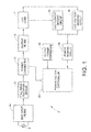
- FIG. 1 is a block diagram of an LED lamp incorporating a power control system according to aspects of the invention
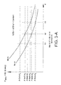
- FIG. 2A is a graph showing LED current as a function of LED forward voltage at different temperatures and different binning
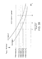
- FIG. 2B is a graph showing LED current as a function of LED voltage at different temperatures and different aging
- FIG. 3A is a graph showing LED power as a function of temperature and V F binning
- FIG. 3B is a graph showing LED output power as a function of temperature and LED aging
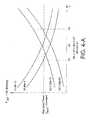
- FIG. 4A is a graph showing LED regulated power as a function of temperature and how the LED current is adjusted by a controllable dc voltage and current source as a function of the LED forward voltage variations due to temperature;
- FIG. 4B is a graph showing LED regulated power as a function of temperature and how the LED current is adjusted by a controllable dc voltage and current source as a function of the LED forward voltage variations due to aging;
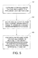
- FIG. 5 is a flow chart illustrating an exemplary method of maintaining the intensity and power consumption of a light source substantially constant.
- LED light-emitting diode
- a light source such as a light-emitting diode (LED) traffic signal lamp
- LED lighting applications such as rail signals, signage, commercial refrigeration, general illumination, vehicle lighting, variable message and many other applications, and it should be understood that this example is not intended to limit the range of applications of the present invention.
- FIG. 1 shows a block diagram of a light source 2, such as an LED traffic signal lamp.
- the light source 2 includes a non-linear load 4 comprising at least one set of LEDs.
- the set is typically formed of a plurality of subsets of LEDs, wherein the LEDs within each subset are serially interconnected.
- the subsets of serially interconnected LEDs are generally connected in parallel to form the set.
- the light source 2 is supplied by an ac input line 6.
- the voltage and current from the ac input line 6 is rectified by a full wave rectifier bridge 8 and is supplied to the LED load 4 through a power converter (or power supply) 10 and an output filter 12.
- the power converter 10 takes the ac voltage from the ac input line 6 and transforms it into dc voltage, with a regulated current, to power the LED load 4.
- a switching power supply may be used.
- an electromagnetic compatibility (EMC) input filter 14 may be added between the ac source 6 and the full wave rectifier bridge 8.
- the EMC input filter 14 typically contains an arrangement of capacitors, inductors and common mode chokes to reduce conducted electromagnetic emissions. Filtering is necessary due to the noisy nature of a switching power supply.
- the current flowing through the EMC input filter 14 is proportional to the full-wave rectified voltage at the output of the rectifier bridge 8.
- the current waveform is sinusoidal and in phase with the voltage waveform so that the power factor is, if not equal to, close to unity.
- the LED load 4 is connected to an LED current sensing circuit 16 that can be employed to verify that the current drawn by the LED load 4 is within acceptable operating parameters. Also, the LED load 4 is connected to an LED voltage sensing circuit 18. The outputs of the LED current sensing circuit 16 and the LED voltage sensing circuit 18, respectively, are connected to a power sensing (or multiplier) circuit 20.
- the fixed output power reference signal P REF for each subset of LEDs is represented in FIG. 1 by reference numeral 22.
- the power drawn by the LED load 4 is thus measured by the power sensing circuit 20, which is serially interconnected between the terminals of a power factor controller 24 and the LED current sensing circuit 16 and the LED voltage sensing circuit 18.
- the power sensing circuit 20 generally multiplies the LED current I LED and the LED voltage V LED ( i.e., I LED x V LED ) sensed by the current sensing circuit 16 and the voltage sensing circuit 18, respectively. In this manner, the power sensing circuit 20 converts the total power drawn by the LED load 4 to a corresponding power-representative voltage signal P MEAS present on an output of the power sensing circuit 20.
- the power sensing circuit 20 may comprise an analog multiplier circuit or a digital multiplier circuit.
- the corresponding power-representative voltage signal from the power sensing circuit 20 is connected to a power factor controller 24.
- a function of the power factor controller 24 is to ensure that the input current follows the input voltage in time and amplitude proportionally. This means that, for steady-state constant output power conditions, the input current amplitude will follow the input voltage amplitude in the same proportion at any instant in time.
- the power factor controller 24 requires on its input at least two parameters: (1) the power representative feedback signal P MEAS (generated by the power sensing circuit 20) that varies with the LED load variation and (2) the output power reference P REF .
- the output power control loop which comprises at least three circuits (in this case, the LED current sensing circuit 16, the LED voltage sensing circuit 18 and the power sensing circuit 20), is forced to have a slow response to allow the input current to follow the input voltage. Because of this slow power loop response, it is necessary to optimize the power factor controller 24 with respect to its action on the power converter 10 as a function of the temperature and forward voltage variation.
- the power sensing circuit 22 multiplies the output current and the output voltage.
- the power-representative feedback signal P MEAS is then compared to P REF in a comparator within the power factor controller 24.
- the light source 2 may also include other circuits and components, including, but not limited to, an electronic safeguarding circuit, an input under/over voltage circuit, a start-up circuit, an input reference current sense, a dimming option circuit, and/or a light-out detection circuit, all as known to a person having ordinary skill in the art.
- LED manufacturers typically bin or separate LEDs subsequent to a production run. Due to typical variations during manufacturing, each LED may possess and exhibit a unique set of characteristics. LED manufactures normally bin according to three primary characteristics. The intensity bins segregate components in accordance with luminous output. Color bins provide separation for variations in optical wavelength or color temperature. Voltage bins divide components according to variations of their forward voltage rating.
- FIG. 2A is a graph showing LED current (I LED ) measurements at various binnings with respect to LED forward voltage variations when no power control circuitry according to the present invention is incorporated.
- temperature ⁇ 1 is lower than temperature ⁇ 2 , which is itself lower than temperature ⁇ 3 .
- I LEDref the LED voltage corresponding to Bin A V F1 is greater than the LED voltage corresponding to Bin A V F2 , which is itself greater than the LED voltage corresponding to Bin A V F3 , and the same characteristics hold for the LED voltages corresponding to Bin B V' F1 , V' F2 and V' F3 , respectively.
- FIG. 2B LED current (I LED ) measurements at various agings are shown with respect to LED forward voltage variations when no power control circuitry according to the present invention is incorporated.
- temperature ⁇ 1 is lower than temperature ⁇ 2 , which is itself lower than temperature ⁇ 3 .
- I LEDref the LED voltage corresponding to Aging1 V FA1 is greater than the LED voltage corresponding to Aging1 V FA2 , which is itself greater than the LED voltage corresponding to Aging1 V FA3 , and the same characteristics hold for the LED voltages corresponding to Aging2 V' FA1 , V' FA2 and V' FA3 , respectively.
- FIG. 3A is a graph of LED Power (P MEAS ) measurements at various binnings with respect to LED forward voltage when no power control circuitry according to the present invention is incorporated.
- temperature ⁇ 1 is lower than temperature ⁇ 2 , which is itself lower than temperature ⁇ 3 .
- I LEDref reference LED constant current
- the LED power corresponding to Bin A P-BinA- ⁇ 1 is greater than the LED power corresponding to Bin A P-BinA- ⁇ 2, which is itself greater than the LED power corresponding to Bin A P-BinA- ⁇ 3, and the same thing holds for Bin B: P-BinB- ⁇ 1 > P-BinB- ⁇ 2> P-BinB- ⁇ 3.
- FIG. 3B is a graph of LED Power (P MEAS ) measurements at various agings with respect to LED forward voltage when no power control circuitry according to the present invention is incorporated.
- P MEAS LED Power
- FIG. 3A shows that without the power sense circuit 20 of this invention, at a lower temperature ( ⁇ 1 ), the LED output power P MEAS1 at a given V F binning is higher, and at the higher temperature ( ⁇ 3 ), the LED output power P MEAS3 is lower at a given V F binning. Also, at a lower temperature ( ⁇ 1 ), the LED output power P MEASA1 at a given aging is higher, and at the higher temperature ( ⁇ 3 ), the LED output power P MEASA3 is lower at given aging, that is: P MEAS ⁇ 1 > P MEAS ⁇ 2 > P MEAS ⁇ 3
- the LED power-representative voltage signal P MEAS is given by the product of LED current I LED (from the LED current sensing circuit 16) and LED Forward Voltage V LED (from the LED voltage sensing circuit 18).
- the LED power-representative voltage signal P MEAS has an amplitude that is proportional to the magnitude of the current flowing through the LEDs 14 and the voltage across the LEDs 14.
- the power sensing circuit 20 enables regulation of the dc power supplied to the LEDs as a function of temperature ⁇ , V F binning and aging. When the temperature ⁇ is constant, P MEAS as generated by the power sensing circuit 20 will depend only on V F binning and aging.
- FIGS. 4A and 4B represent the effect of the power control circuitry being incorporated into the light source 2.
- the power drawn by the LED load 4 is therefore limited by the choice of P REF . This, in turn, maintains a roughly constant power output from the LED load 4.
- the power factor controller 24 increases the LED current by sending a signal to the power converter 10 to increase the current to maintain the power constant and equal to P REF .
- P MEAS increases, and the difference E decreases so that the power converter 10 decreases the current in the LED load 4 until the difference E is again equal to zero.
- the LED lamp power output regulation is based on the variation of forward voltage measurement with temperature and aging as shown in FIGS. 4A and 4B .
- the power of the LEDs may be adjusted so that if any of the LED electrical characteristics changes, the LED power consumption stays constant. If the LED forward voltage varies, for example, with (a) temperature, (b) a manufacturer batch to batch, (c) manufacturer V F binning, or (d) age, the LED current may be adjusted to maintain the same power consumption.
- the LED power consumption can also be changed in function of the line input voltage resulting in LED efficiency having a low variation in terms of lumen per watt but having a high variation in terms of voltage for a specific current.
- the output power reference can be adjusted by the customer as a dimming option.
- An input reference current sensor is generally proportional to the output power P MEAS , so by fixing the reference current, the output power reference can be fixed proportionally and then the dimming option can be executed with the same power consumption in all temperature environments, binning V F variations and age variations (time).
- FIG. 5 An exemplary method of maintaining the intensity and power consumption of a light source substantially constant, in accordance with the exemplary embodiment shown in FIG. 1 and described above, is presented in FIG. 5 .
- the method includes (a) supplying power from a controllable power source to a non-linear light-emitting load such as a set of LEDs (101); (b) multiplying an output forward voltage and a variable current-representative signal from the light-emitting load to generate a variable power-representative signal (102); and (c) feedback controlling the power source in relation to the variable power-representative signal to maintain the light intensity produced by the light source substantially constant (103).
Abstract
Description
- The present invention relates to a power control circuit for providing a substantially constant intensity light source and a corresponding method using this control circuit.
- By way of background, traffic signal lamps typically use either incandescent or LED (light-emitting diode) lamps. LED traffic signals are more reliable, more mechanically stable, safer, more energy efficient and more environmentally friendly than incandescent lamps. Thus, LED traffic signals are gaining in popularity.
- The voltage and current characteristics of an LED lamp are sensitive to temperature. The LEDs used will have a forward voltage specified at an intended operating current. In particular, the forward voltage changes with the temperature, and, consequently, the current follows the variation. Thus, if the forward voltage increases, then the forward current will decrease. Likewise, if the forward voltage decreases, then the forward current increases.
- For example, for a given type of LED widely used in the fabrication of traffic lights and signals, rail signals, signage, commercial refrigeration lighting, general Illumination, vehicle lighting, variable message and many other applications, a constant voltage of 1.8 volts will produce in the LED a current of about 7.5 mA at a temperature of -25° C, a current of about 20.5 mA at a temperature of +25° C, and a current of about 30 mA at a temperature of +60° C. The magnitude of the current through the light-emitting diode at a temperature of +60° C is therefore, for a constant voltage of 1.8 volt, about 1.6 times higher than the magnitude of the current at a temperature of +25° C.
- A constant voltage may be maintained such that the voltage across the LEDs is constant for all environments (e.g., -40 to 74 °C). It is known that at high temperatures the forward voltage of the LEDs decreases, and because the driver or the power supply maintains the voltage across the LEDs constant, the LED current will increase exponentially and stress the LEDs (bright LEDs).
- At low temperatures the forward voltage of the LEDs increases, and because the driver of the power supply maintains the voltage across the LEDs constant, the LED current will decrease exponentially and the light will be dim (dim LEDs). Therefore, voltage feedback control may be detrimental to the service life of such an LED.
- Also, a fixed LED output current presents the following drawbacks: at higher temperature the LED forward voltage decreases and then the output LED power decreases, which means light out decreases; and at lower temperatures the LED forward voltage increases and then the output LED power increases, which means light out increases.
- Thus, there is a need for a device and method that eliminates the above-discussed drawbacks of the prior art by regulating the output power, and hence the light intensity, of non-linear light emitting loads such as light-emitting diodes.
- The following patents, the disclosures of each being totally incorporated herein by reference, are mentioned:
-
U.S. Patent No. 6,091,614 to Malenfant , entitled "VOLTAGE BOOSTER FOR ENABLING THE POWER FACTOR CONTROLLER OF A LED LAMP UPON LOW AC OR DC SUPPLY;" -
U.S. Patent No. 6,285,139 to Ghanem , entitled "NON-LINEAR LIGHT-EMITTING LOAD CURRENT CONTROL;" and -
U.S. Patent No. 6,400,102 to Ghanem , entitled "NON-LINEAR LIGHT-EMITTING LOAD CURRENT CONTROL." - In accordance with an aspect of the present invention a light source is provided. The light source includes a controllable power source for supplying power to a non-linear light-emitting load; a current sensing circuit connected to the non-linear light-emitting load that generates a current signal representing the current flowing through the non-linear light-emitting load; a voltage sensing circuit connected to the non-linear light-emitting load that generates a voltage signal representing the voltage across the non-linear light-emitting load; a power sensing circuit connected to the current and voltage sensing circuits that receives the current and voltage signals and measures the power consumption of the light-emitting load and generates a variable power-representative signal; and a power feedback control circuit connected between the power sensing circuit and the controllable power source through which the power source is controlled in relation to the variable power-representative signal to maintain the power consumption of the light source substantially constant.
- In accordance with another aspect of the present invention a method of maintaining the intensity and power consumption of a light source substantially constant is provided. The method includes supplying a controllable dc voltage and current to a non-linear light-emitting load; multiplying an output forward voltage and a variable current-representative signal from the light-emitting load to generate a variable power-representative signal; and feedback controlling the controllable dc voltage and current in relation to the variable power-representative signal to keep the light intensity produced by the light source substantially constant.
- In accordance with yet another aspect of the present invention a substantially constant intensity LED lamp is provided. The lamp includes a controllable dc voltage and current source for supplying an LED load with dc voltage and current; a current sensing circuit connected with the LED load that generates a current signal representing the current flowing through the LED load; a voltage sensing circuit connected with the LED load that generates a voltage signal representing the voltage across the LED load; a multiplier circuit that receives the current signal and the voltage signal and generates a variable-power representative signal; and a voltage and current control feedback circuit connected between the power sense circuit and the controllable dc voltage and current source that receives the variable-power representative signal and controls the dc voltage and current source in relation to the variable power-representative signal to thereby adjust the dc voltage and current to keep the light intensity and power consumption produced by the LED load substantially constant.
- Suitably, the power consumption of the light-emitting load varies as a result of at least one of an environmental condition of operation, manufacturer forward voltage binning batch and age of the light-emitting load
- Suitably, the voltage sensing circuit produces a voltage representative signal, the voltage varying with the temperature, binning batch and aging of the light-emitting load.
- Suitably the power feedback control circuit comprises: a comparator having a first input for receiving the variable power-representative signal, a second input for receiving a fixed power-representative reference signal, and an output for producing a comparison-representative signal representative of a comparison between the variable power-representative signal and the fixed power-representative reference signal; and
a controller through which the power source is controlled in relation to the comparison-representative signal to adjust the output of the power supply such that the power consumption and light intensity produced by the light source are substantially constant. - Suitably, the power consumption and light source intensity are kept substantially constant within a given temperature range.
- Suitably, the non-linear light-emitting load comprises a plurality of subsets of serially interconnected LEDs.
- Suitably, the non-linear light-emitting load comprises a plurality of subsets of serially interconnected LEDs that are connected in parallel.
- Suitably, the LED lamp further comprises at least one of the following circuits:
- an electronic safeguarding circuit;
- an input under/over voltage circuit;
- a start-up circuit;
- an input reference current sense circuit;
- a dimming option circuit; and
- a light-out detection circuit.
- Suitably, feedback controlling further comprises:
- comparing the variable power-representative signal and a fixed power-representative reference signal to produce a comparison-representative signal representative of a comparison between the variable power-representative signal and the fixed power-representative reference signal; and
- controlling the controllable dc voltage and current in relation to the comparison-representative signal to adjust the dc voltage and current such that the power consumption and light intensity produced by the light source are substantially constant.
- Suitably, the method comprises a non-linear light-emitting load that comprises a plurality of subsets of serially interconnected LEDs.
- Suitably, the method comprises a non-linear light-emitting load that comprises subsets of serially interconnected LEDs that are generally connected in parallel.
- The term "substantially constant" means that the power consumption and/or the light intensity produced by the light source varies by less than +/- 10% of the stated value for the power consumption and/or for the light intensity. Suitably, the power consumption and/or the light intensity produced by the light source varies by less than +/- 7% of the stated values; suitably by less than +/- 5%; suitably by less than +/- 4%; suitably by less than +/- 3%; suitably by less than +/- 2%; suitably by less than +/- 1 %; suitably by less than +/- 0.5%.
- The present invention exists in the construction, arrangement, and combination of the various parts of the device, and steps of the method, whereby the objects contemplated are attained as hereinafter more fully set forth, specifically pointed out in the claims, and illustrated in the accompanying drawings in which:
-
FIG. 1 is a block diagram of an LED lamp incorporating a power control system according to aspects of the invention; -
FIG. 2A is a graph showing LED current as a function of LED forward voltage at different temperatures and different binning; -
FIG. 2B is a graph showing LED current as a function of LED voltage at different temperatures and different aging; -
FIG. 3A is a graph showing LED power as a function of temperature and VF binning; -
FIG. 3B is a graph showing LED output power as a function of temperature and LED aging; -
FIG. 4A is a graph showing LED regulated power as a function of temperature and how the LED current is adjusted by a controllable dc voltage and current source as a function of the LED forward voltage variations due to temperature; -
FIG. 4B is a graph showing LED regulated power as a function of temperature and how the LED current is adjusted by a controllable dc voltage and current source as a function of the LED forward voltage variations due to aging; and -
FIG. 5 is a flow chart illustrating an exemplary method of maintaining the intensity and power consumption of a light source substantially constant. - Although the exemplary embodiments of the present invention will be described hereinafter with reference to a light source such as a light-emitting diode (LED) traffic signal lamp, it may be used in other LED lighting applications such as rail signals, signage, commercial refrigeration, general illumination, vehicle lighting, variable message and many other applications, and it should be understood that this example is not intended to limit the range of applications of the present invention.
- Referring now to the drawings wherein the showings are for purposes of illustrating the exemplary embodiments only and not for purposes of limiting the claimed subject matter,
FIG. 1 shows a block diagram of alight source 2, such as an LED traffic signal lamp. Thelight source 2 includes anon-linear load 4 comprising at least one set of LEDs. The set is typically formed of a plurality of subsets of LEDs, wherein the LEDs within each subset are serially interconnected. The subsets of serially interconnected LEDs are generally connected in parallel to form the set. - The
light source 2 is supplied by an ac input line 6. The voltage and current from the ac input line 6 is rectified by a fullwave rectifier bridge 8 and is supplied to theLED load 4 through a power converter (or power supply) 10 and anoutput filter 12. - The
power converter 10 takes the ac voltage from the ac input line 6 and transforms it into dc voltage, with a regulated current, to power theLED load 4. A switching power supply may be used. - To smooth out the ac current waveform and withdraw the switching high frequencies therefrom, an electromagnetic compatibility (EMC)
input filter 14 may be added between the ac source 6 and the fullwave rectifier bridge 8.
TheEMC input filter 14 typically contains an arrangement of capacitors, inductors and common mode chokes to reduce conducted electromagnetic emissions. Filtering is necessary due to the noisy nature of a switching power supply. The current flowing through theEMC input filter 14 is proportional to the full-wave rectified voltage at the output of therectifier bridge 8. The current waveform is sinusoidal and in phase with the voltage waveform so that the power factor is, if not equal to, close to unity. - The
LED load 4 is connected to an LEDcurrent sensing circuit 16 that can be employed to verify that the current drawn by theLED load 4 is within acceptable operating parameters. Also, theLED load 4 is connected to an LEDvoltage sensing circuit 18. The outputs of the LEDcurrent sensing circuit 16 and the LEDvoltage sensing circuit 18, respectively, are connected to a power sensing (or multiplier)circuit 20. - The fixed output power reference signal PREF for each subset of LEDs is represented in
FIG. 1 byreference numeral 22. The power drawn by theLED load 4 is thus measured by thepower sensing circuit 20, which is serially interconnected between the terminals of apower factor controller 24 and the LEDcurrent sensing circuit 16 and the LEDvoltage sensing circuit 18. Thepower sensing circuit 20 generally multiplies the LED current ILED and the LED voltage VLED (i.e., ILED x VLED) sensed by thecurrent sensing circuit 16 and thevoltage sensing circuit 18, respectively. In this manner, thepower sensing circuit 20 converts the total power drawn by theLED load 4 to a corresponding power-representative voltage signal PMEAS present on an output of thepower sensing circuit 20. Thepower sensing circuit 20 may comprise an analog multiplier circuit or a digital multiplier circuit. The corresponding power-representative voltage signal from thepower sensing circuit 20 is connected to apower factor controller 24. - A function of the
power factor controller 24 is to ensure that the input current follows the input voltage in time and amplitude proportionally. This means that, for steady-state constant output power conditions, the input current amplitude will follow the input voltage amplitude in the same proportion at any instant in time. Thepower factor controller 24 requires on its input at least two parameters: (1) the power representative feedback signal PMEAS (generated by the power sensing circuit 20) that varies with the LED load variation and (2) the output power reference PREF. - The output power control loop, which comprises at least three circuits (in this case, the LED
current sensing circuit 16, the LEDvoltage sensing circuit 18 and the power sensing circuit 20), is forced to have a slow response to allow the input current to follow the input voltage. Because of this slow power loop response, it is necessary to optimize thepower factor controller 24 with respect to its action on thepower converter 10 as a function of the temperature and forward voltage variation. - As noted earlier, to obtain the power-representative feedback signal PMEAS, the
power sensing circuit 22 multiplies the output current and the output voltage. The power-representative feedback signal PMEAS is then compared to PREF in a comparator within thepower factor controller 24. - Although not shown in
FIG. 1 , it is to be understood that thelight source 2 may also include other circuits and components, including, but not limited to, an electronic safeguarding circuit, an input under/over voltage circuit, a start-up circuit, an input reference current sense, a dimming option circuit, and/or a light-out detection circuit, all as known to a person having ordinary skill in the art. - It is to be appreciated that LED manufacturers typically bin or separate LEDs subsequent to a production run. Due to typical variations during manufacturing, each LED may possess and exhibit a unique set of characteristics. LED manufactures normally bin according to three primary characteristics. The intensity bins segregate components in accordance with luminous output. Color bins provide separation for variations in optical wavelength or color temperature. Voltage bins divide components according to variations of their forward voltage rating.
- Referring now to
FIG. 2A , which is a graph showing LED current (ILED) measurements at various binnings with respect to LED forward voltage variations when no power control circuitry according to the present invention is incorporated. InFIG. 2A , note that temperature θ1 is lower than temperature θ2, which is itself lower than temperature θ3. Note that at a reference LED current (ILEDref), the LED voltage corresponding to Bin A VF1 is greater than the LED voltage corresponding to Bin A VF2, which is itself greater than the LED voltage corresponding to Bin A VF3, and the same characteristics hold for the LED voltages corresponding to Bin B V'F1, V'F2 and V'F3, respectively. - Turning now to
FIG. 2B , LED current (ILED) measurements at various agings are shown with respect to LED forward voltage variations when no power control circuitry according to the present invention is incorporated. InFIG. 2B , temperature θ1 is lower than temperature θ2, which is itself lower than temperature θ3. Note that at a reference LED current (ILEDref), the LED voltage corresponding to Aging1 VFA1 is greater than the LED voltage corresponding to Aging1 VFA2, which is itself greater than the LED voltage corresponding to Aging1 VFA3, and the same characteristics hold for the LED voltages corresponding to Aging2 V'FA1, V'FA2 and V'FA3, respectively. -
FIG. 3A is a graph of LED Power (PMEAS) measurements at various binnings with respect to LED forward voltage when no power control circuitry according to the present invention is incorporated. InFIG. 3A , temperature θ1 is lower than temperature θ2, which is itself lower than temperature θ3. Note that at a reference LED constant current (ILEDref), the LED power corresponding to Bin A P-BinA-θ1 is greater than the LED power corresponding to Bin A P-BinA-θ2, which is itself greater than the LED power corresponding to Bin A P-BinA-θ3, and the same thing holds for Bin B: P-BinB-θ1 > P-BinB-θ2> P-BinB-θ3. -
FIG. 3B is a graph of LED Power (PMEAS) measurements at various agings with respect to LED forward voltage when no power control circuitry according to the present invention is incorporated. InFIG. 3B , note that at a reference LED constant current (ILEDref), the LED power corresponding to Aging1, P-Aging1-θ 1 is greater than the corresponding to LED power corresponding to Aging1, P-Aging1-θ 2, which is itself greater than the LED power corresponding to Aging1, P-Agingl-θ 3, and the same thing holds for Aging2: P-Aging2-θ 1 > Aging2, P-Aging2-θ 2 > Aging2, P-Aging1- θ 3. -
FIG. 3A shows that without thepower sense circuit 20 of this invention, at a lower temperature (θ1), the LED output power PMEAS1 at a given VF binning is higher, and at the higher temperature (θ3), the LED output power PMEAS3 is lower at a given VF binning. Also, at a lower temperature (θ1), the LED output power PMEASA1 at a given aging is higher, and at the higher temperature (θ3), the LED output power PMEASA3 is lower at given aging, that is:

- Accordingly, in order to avoid variations in the LED output power PMEAS with temperature θ1, aging and VF binning at a fixed current, the
power sensing circuit 20 has been introduced. The LED power-representative voltage signal PMEAS is given by the product of LED current ILED (from the LED current sensing circuit 16) and LED Forward Voltage VLED (from the LED voltage sensing circuit 18). - The LED power-representative voltage signal PMEAS has an amplitude that is proportional to the magnitude of the current flowing through the
LEDs 14 and the voltage across theLEDs 14. Thepower sensing circuit 20 enables regulation of the dc power supplied to the LEDs as a function of temperature θ, VF binning and aging. When the temperature θ is constant, PMEAS as generated by thepower sensing circuit 20 will depend only on VF binning and aging. - We refer now to
FIGS. 4A and4B , which represent the effect of the power control circuitry being incorporated into thelight source 2. As shown inFIGS. 4A and4B , when the temperature θ rises, the forward voltage decreases, and then thepower factor controller 24 increases the LED current by sending a signal to thepower converter 10 to increase the current) to maintain the power consumption constant such that:
and the current on the LEDs is:
where PREF is the fixed LED power reference. - As a result, the LED voltage VLED diminishes, and the difference E between the fixed reference power PREF and the filtered LED load power measurement PMEAS increases, so that the LED current is increased by the
power converter 10 until the difference E is equal to zero:
- The power drawn by the
LED load 4 is therefore limited by the choice of PREF. This, in turn, maintains a roughly constant power output from theLED load 4. - Conversely, if the temperature θ drops, the LED voltage VLED increases, and the
power factor controller 24 increases the LED current by sending a signal to thepower converter 10 to increase the current to maintain the power constant and equal to PREF. As a result, PMEAS increases, and the difference E decreases so that thepower converter 10 decreases the current in theLED load 4 until the difference E is again equal to zero. - The LED lamp power output regulation is based on the variation of forward voltage measurement with temperature and aging as shown in
FIGS. 4A and4B . - Thus, in accordance with aspects of the present invention, the power of the LEDs may be adjusted so that if any of the LED electrical characteristics changes, the LED power consumption stays constant. If the LED forward voltage varies, for example, with (a) temperature, (b) a manufacturer batch to batch, (c) manufacturer VF binning, or (d) age, the LED current may be adjusted to maintain the same power consumption. The LED power consumption can also be changed in function of the line input voltage resulting in LED efficiency having a low variation in terms of lumen per watt but having a high variation in terms of voltage for a specific current.
- The output power reference can be adjusted by the customer as a dimming option. An input reference current sensor is generally proportional to the output power PMEAS, so by fixing the reference current, the output power reference can be fixed proportionally and then the dimming option can be executed with the same power consumption in all temperature environments, binning VF variations and age variations (time).
- An exemplary method of maintaining the intensity and power consumption of a light source substantially constant, in accordance with the exemplary embodiment shown in
FIG. 1 and described above, is presented inFIG. 5 . The method includes (a) supplying power from a controllable power source to a non-linear light-emitting load such as a set of LEDs (101); (b) multiplying an output forward voltage and a variable current-representative signal from the light-emitting load to generate a variable power-representative signal (102); and (c) feedback controlling the power source in relation to the variable power-representative signal to maintain the light intensity produced by the light source substantially constant (103). - The above description merely provides a disclosure of particular embodiments of the invention and is not intended for the purposes of limiting the same thereto. As such, the invention is not limited to only the above-described embodiments. Rather, it is recognized that one of ordinary skill in the art could conceive alternative embodiments that fall within the scope of the invention.
Claims (13)
- A light source comprising:a controllable power source for supplying power to a non-linear light-emitting load;a current sensing circuit connected to the non-linear light-emitting load that generates a current signal representing the current flowing through the non-linear light-emitting load;a voltage sensing circuit connected to the non-linear light-emitting load that generates a voltage signal representing the voltage across the non-linear light-emitting load;a power sensing circuit connected to the current and voltage sensing circuits that receives the current and voltage signals and measures the power consumption of the light-emitting load and generates a variable power-representative signal; anda power feedback control circuit connected between the power sensing circuit and the controllable power source through which the power source is controlled in relation to the variable power-representative signal to maintain the power consumption of the light source substantially constant.
- A substantially constant intensity LED lamp comprising:a controllable dc voltage and current source for supplying an LED load with dc voltage and current;a current sensing circuit connected with the LED load that generates a current signal representing the current flowing through the LED load;a voltage sensing circuit connected with the LED load that generates a voltage signal representing the voltage across the LED load;a multiplier circuit that receives the current signal and the voltage signal and generates a variable-power representative signal; anda voltage and current control feedback circuit connected between the power sense circuit and the controllable dc voltage and current source that receives the variable-power representative signal and controls the dc voltage and current source in relation to the variable power-representative signal to thereby adjust the dc voltage and current to keep the light intensity and power consumption produced by the LED load substantially constant.
- The LED lamp as defined in one of the preceding claims, wherein the power consumption of the light-emitting load varies as a result of at least one of an environmental condition of operation, manufacturer forward voltage binning batch and age of the light-emitting load.
- The LED lamp as defined in one of the preceding claims, wherein the voltage sensing circuit produces a voltage representative signal, the voltage varying with the temperature, binning batch and aging of the light-emitting load.
- The LED lamp as defined in one of the preceding claims, wherein the power feedback control circuit comprises:a comparator having a first input for receiving the variable power-representative signal, a second input for receiving a fixed power-representative reference signal, and an output for producing a comparison-representative signal representative of a comparison between the variable power-representative signal and the fixed power-representative reference signal; anda controller through which the power source is controlled in relation to the comparison-representative signal to adjust the output of the power supply such that the power consumption and light intensity produced by the light source are substantially constant.
- The LED lamp as defined in one of the preceding claims, wherein the power consumption and light source intensity are kept substantially constant within a given temperature range.
- LED lamp as defined in one of the preceding claims, wherein the non-linear light-emitting load comprises a plurality of subsets of serially interconnected LEDs.
- The LED lamp as defined in one of the preceding claim, wherein the non-linear light-emitting load comprises a plurality of subsets of serially interconnected LEDs that are connected in parallel.
- The LED lamp as defined in one of the preceding claims, further comprising at least one of the following circuits:an electronic safeguarding circuit;an input under/over voltage circuit;a start-up circuit;an input reference current sense circuit;a dimming option circuit; anda light-out detection circuit.
- A method of maintaining the intensity and power consumption of a light source substantially constant, the method comprising:supplying a controllable dc voltage and current to a non-linear light-emitting load;multiplying an output forward voltage and a variable current-representative signal from the light-emitting load to generate a variable power-representative signal; andfeedback controlling the controllable dc voltage and current in relation to the variable power-representative signal to keep the light intensity produced by the light source substantially constant.
- The method as defined in claim 10, wherein feedback controlling further comprises:comparing the variable power-representative signal and a fixed power-representative reference signal to produce a comparison-representative signal representative of a comparison between the variable power-representative signal and the fixed power-representative reference signal; andcontrolling the controllable dc voltage and current in relation to the comparison-representative signal to adjust the dc voltage and current such that the power consumption and light intensity produced by the light source are substantially constant.
- The method as defined in claim 11, wherein the non-linear light-emitting load comprises a plurality of subsets of serially interconnected LEDs.
- The method as defined in claim 11 or 12, wherein the non-linear light-emitting load comprises a plurality of subsets of serially interconnected LEDs that are connected in parallel.
Applications Claiming Priority (1)
| Application Number | Priority Date | Filing Date | Title |
|---|---|---|---|
| US12/420,923 US8174197B2 (en) | 2009-04-09 | 2009-04-09 | Power control circuit and method |
Publications (2)
| Publication Number | Publication Date |
|---|---|
| EP2239997A1 true EP2239997A1 (en) | 2010-10-13 |
| EP2239997B1 EP2239997B1 (en) | 2015-05-20 |
Family
ID=42272054
Family Applications (1)
| Application Number | Title | Priority Date | Filing Date |
|---|---|---|---|
| EP20100159471 Active EP2239997B1 (en) | 2009-04-09 | 2010-04-09 | Power control circuit and method |
Country Status (3)
| Country | Link |
|---|---|
| US (1) | US8174197B2 (en) |
| EP (1) | EP2239997B1 (en) |
| CN (1) | CN101861007B (en) |
Cited By (8)
| Publication number | Priority date | Publication date | Assignee | Title |
|---|---|---|---|---|
| EP2645815A1 (en) * | 2012-03-27 | 2013-10-02 | Koninklijke Philips N.V. | LED lighting system |
| EP2765829A3 (en) * | 2013-02-08 | 2015-10-21 | Hep Tech Co. Ltd. | Constant-power power supply apparatus and method of supplying constant-power power |
| EP2785144A3 (en) * | 2013-03-27 | 2015-10-21 | Hep Tech Co. Ltd. | Driving apparatus for LED chips of different specifications |
| EP2876978A3 (en) * | 2013-09-16 | 2015-11-04 | Hep Tech Co. Ltd. | Method of driving LED chips of same power but different rated voltages and currents |
| US9554436B2 (en) | 2013-07-24 | 2017-01-24 | Philips Lighting Holding B.V. | Power supply for LED lighting system |
| WO2018114931A3 (en) * | 2016-12-20 | 2018-08-16 | Osram Opto Semiconductors Gmbh | Video wall module |
| WO2021013699A1 (en) * | 2019-07-24 | 2021-01-28 | Eldolab Holding B.V. | Smart starting up method by an led driver |
| EP4123894A1 (en) * | 2021-07-19 | 2023-01-25 | Infineon Technologies Austria AG | Power supply system and current control based on consumption by dynamic loads |
Families Citing this family (60)
| Publication number | Priority date | Publication date | Assignee | Title |
|---|---|---|---|---|
| US9509525B2 (en) | 2008-09-05 | 2016-11-29 | Ketra, Inc. | Intelligent illumination device |
| US8773336B2 (en) | 2008-09-05 | 2014-07-08 | Ketra, Inc. | Illumination devices and related systems and methods |
| US9276766B2 (en) | 2008-09-05 | 2016-03-01 | Ketra, Inc. | Display calibration systems and related methods |
| US10210750B2 (en) | 2011-09-13 | 2019-02-19 | Lutron Electronics Co., Inc. | System and method of extending the communication range in a visible light communication system |
| US8358085B2 (en) | 2009-01-13 | 2013-01-22 | Terralux, Inc. | Method and device for remote sensing and control of LED lights |
| US9326346B2 (en) | 2009-01-13 | 2016-04-26 | Terralux, Inc. | Method and device for remote sensing and control of LED lights |
| EP2233826B1 (en) * | 2009-03-17 | 2015-12-16 | Thorn Europhane S.A. | Lighting unit and luminaire for road and/or street lighting |
| US8502476B2 (en) * | 2009-10-16 | 2013-08-06 | Samsung Electronics Co., Ltd | Method and apparatus for controlling power consumption of light source in mobile projector |
| EP2501393B1 (en) | 2009-11-17 | 2016-07-27 | Terralux, Inc. | Led power-supply detection and control |
| KR20120020481A (en) * | 2010-08-30 | 2012-03-08 | 삼성전자주식회사 | Luminescence driving apparatus, display apparatus and driving method thereof |
| US9342058B2 (en) | 2010-09-16 | 2016-05-17 | Terralux, Inc. | Communication with lighting units over a power bus |
| US9596738B2 (en) | 2010-09-16 | 2017-03-14 | Terralux, Inc. | Communication with lighting units over a power bus |
| USRE49454E1 (en) | 2010-09-30 | 2023-03-07 | Lutron Technology Company Llc | Lighting control system |
| US9386668B2 (en) | 2010-09-30 | 2016-07-05 | Ketra, Inc. | Lighting control system |
| WO2012129243A1 (en) | 2011-03-21 | 2012-09-27 | Digital Lumens Incorporated | Methods, apparatus and systems for providing occupancy-based variable lighting |
| DE102011110720A1 (en) * | 2011-08-16 | 2013-02-21 | Austriamicrosystems Ag | Driver arrangement and method for driving at least one light emitting diode |
| CA2854784C (en) | 2011-11-03 | 2021-07-20 | Digital Lumens Incorporated | Methods, systems, and apparatus for intelligent lighting |
| US8896231B2 (en) | 2011-12-16 | 2014-11-25 | Terralux, Inc. | Systems and methods of applying bleed circuits in LED lamps |
| JP5464204B2 (en) * | 2011-12-28 | 2014-04-09 | 株式会社デンソー | Light emission drive device |
| EP2829160B1 (en) * | 2012-03-19 | 2021-04-21 | Digital Lumens Incorporated | Methods, systems, and apparatus for providing variable illumination |
| PT2873299T (en) * | 2012-07-16 | 2019-05-03 | Signify Holding Bv | Driver device and driving method for driving a load, in particular a light unit including controlling input supply current to meet predefined conditions |
| CN102749507B (en) * | 2012-07-25 | 2015-08-05 | 浙江大学 | Light source power detection device |
| US8974077B2 (en) | 2012-07-30 | 2015-03-10 | Ultravision Technologies, Llc | Heat sink for LED light source |
| US9078325B2 (en) | 2012-08-17 | 2015-07-07 | Trw Automotive U.S. Llc | Method and apparatus to control light intensity as voltage fluctuates |
| CN105247961B (en) * | 2012-11-21 | 2021-02-05 | 港大科侨有限公司 | Driver for led lighting and method of driving led lighting |
| WO2014121662A1 (en) * | 2013-02-08 | 2014-08-14 | 东林科技股份有限公司 | Constant-power supply apparatus and constant-power output control method |
| CN103987147B (en) * | 2013-02-08 | 2016-09-28 | 东林科技股份有限公司 | Determine the light emitting diode illuminating apparatus of power and determine the control method of power output |
| CN104080243B (en) * | 2013-03-28 | 2017-06-09 | 东林科技股份有限公司 | Light-emitting diode chip for backlight unit driving method |
| CN104219822A (en) * | 2013-05-31 | 2014-12-17 | 海洋王(东莞)照明科技有限公司 | Heat dissipation circuit |
| US9265119B2 (en) | 2013-06-17 | 2016-02-16 | Terralux, Inc. | Systems and methods for providing thermal fold-back to LED lights |
| US9155155B1 (en) | 2013-08-20 | 2015-10-06 | Ketra, Inc. | Overlapping measurement sequences for interference-resistant compensation in light emitting diode devices |
| US9237620B1 (en) | 2013-08-20 | 2016-01-12 | Ketra, Inc. | Illumination device and temperature compensation method |
| USRE48955E1 (en) | 2013-08-20 | 2022-03-01 | Lutron Technology Company Llc | Interference-resistant compensation for illumination devices having multiple emitter modules |
| USRE48956E1 (en) | 2013-08-20 | 2022-03-01 | Lutron Technology Company Llc | Interference-resistant compensation for illumination devices using multiple series of measurement intervals |
| US9247605B1 (en) | 2013-08-20 | 2016-01-26 | Ketra, Inc. | Interference-resistant compensation for illumination devices |
| US9360174B2 (en) | 2013-12-05 | 2016-06-07 | Ketra, Inc. | Linear LED illumination device with improved color mixing |
| US9345097B1 (en) | 2013-08-20 | 2016-05-17 | Ketra, Inc. | Interference-resistant compensation for illumination devices using multiple series of measurement intervals |
| US9578724B1 (en) | 2013-08-20 | 2017-02-21 | Ketra, Inc. | Illumination device and method for avoiding flicker |
| US9651632B1 (en) | 2013-08-20 | 2017-05-16 | Ketra, Inc. | Illumination device and temperature calibration method |
| US9332598B1 (en) | 2013-08-20 | 2016-05-03 | Ketra, Inc. | Interference-resistant compensation for illumination devices having multiple emitter modules |
| US9769899B2 (en) | 2014-06-25 | 2017-09-19 | Ketra, Inc. | Illumination device and age compensation method |
| US9736895B1 (en) | 2013-10-03 | 2017-08-15 | Ketra, Inc. | Color mixing optics for LED illumination device |
| WO2015051590A1 (en) * | 2013-10-10 | 2015-04-16 | 东林科技股份有限公司 | Drive method applied to light-emitting diode chip with same power but different voltage and current specifications |
| US9736903B2 (en) | 2014-06-25 | 2017-08-15 | Ketra, Inc. | Illumination device and method for calibrating and controlling an illumination device comprising a phosphor converted LED |
| US10161786B2 (en) | 2014-06-25 | 2018-12-25 | Lutron Ketra, Llc | Emitter module for an LED illumination device |
| US9557214B2 (en) | 2014-06-25 | 2017-01-31 | Ketra, Inc. | Illumination device and method for calibrating an illumination device over changes in temperature, drive current, and time |
| US9392663B2 (en) | 2014-06-25 | 2016-07-12 | Ketra, Inc. | Illumination device and method for controlling an illumination device over changes in drive current and temperature |
| US9510416B2 (en) | 2014-08-28 | 2016-11-29 | Ketra, Inc. | LED illumination device and method for accurately controlling the intensity and color point of the illumination device over time |
| US9392660B2 (en) | 2014-08-28 | 2016-07-12 | Ketra, Inc. | LED illumination device and calibration method for accurately characterizing the emission LEDs and photodetector(s) included within the LED illumination device |
| US9237612B1 (en) | 2015-01-26 | 2016-01-12 | Ketra, Inc. | Illumination device and method for determining a target lumens that can be safely produced by an illumination device at a present temperature |
| US9485813B1 (en) | 2015-01-26 | 2016-11-01 | Ketra, Inc. | Illumination device and method for avoiding an over-power or over-current condition in a power converter |
| US9237623B1 (en) | 2015-01-26 | 2016-01-12 | Ketra, Inc. | Illumination device and method for determining a maximum lumens that can be safely produced by the illumination device to achieve a target chromaticity |
| US9660114B2 (en) | 2015-06-25 | 2017-05-23 | International Business Machines Corporation | Temperature stabilization of an on-chip temperature-sensitive element |
| CN105448248B (en) * | 2016-01-15 | 2018-05-08 | 深圳市华星光电技术有限公司 | Power conditioning circuitry and liquid crystal display device |
| CN106655828A (en) * | 2016-12-30 | 2017-05-10 | 广东美的制冷设备有限公司 | Ion purifier, and control method and apparatus thereof |
| CN106602903A (en) * | 2016-12-30 | 2017-04-26 | 广东美的制冷设备有限公司 | Air purifier and control device and method of ion generator |
| US11272599B1 (en) | 2018-06-22 | 2022-03-08 | Lutron Technology Company Llc | Calibration procedure for a light-emitting diode light source |
| CN109195254A (en) * | 2018-09-27 | 2019-01-11 | 厦门普为光电科技有限公司 | A kind of anti-flashing light protection system and method |
| USD926944S1 (en) | 2019-11-25 | 2021-08-03 | Joseph P. Marcilese | Fluid connector |
| CN113163547A (en) * | 2021-02-02 | 2021-07-23 | 上汽大众汽车有限公司 | Self-learning diagnosis system and diagnosis method of LED light source |
Citations (6)
| Publication number | Priority date | Publication date | Assignee | Title |
|---|---|---|---|---|
| US6091614A (en) | 1997-12-17 | 2000-07-18 | Ecolux Inc. | Voltage booster for enabling the power factor controller of a LED lamp upon low ac or dc supply |
| US6285139B1 (en) | 1999-12-23 | 2001-09-04 | Gelcore, Llc | Non-linear light-emitting load current control |
| US20050002134A1 (en) * | 2003-07-02 | 2005-01-06 | Toko, Inc. | Switching-type constant current power supply device |
| WO2006096638A2 (en) * | 2005-03-04 | 2006-09-14 | International Rectifier Corporation | Automotive high intensity discharge lamp ballast circuit |
| US20070024213A1 (en) * | 2005-07-28 | 2007-02-01 | Synditec, Inc. | Pulsed current averaging controller with amplitude modulation and time division multiplexing for arrays of independent pluralities of light emitting diodes |
| US20080018261A1 (en) * | 2006-05-01 | 2008-01-24 | Kastner Mark A | LED power supply with options for dimming |
Family Cites Families (6)
| Publication number | Priority date | Publication date | Assignee | Title |
|---|---|---|---|---|
| US6618031B1 (en) * | 1999-02-26 | 2003-09-09 | Three-Five Systems, Inc. | Method and apparatus for independent control of brightness and color balance in display and illumination systems |
| US6153985A (en) * | 1999-07-09 | 2000-11-28 | Dialight Corporation | LED driving circuitry with light intensity feedback to control output light intensity of an LED |
| US6762563B2 (en) * | 1999-11-19 | 2004-07-13 | Gelcore Llc | Module for powering and monitoring light-emitting diodes |
| US6577072B2 (en) * | 1999-12-14 | 2003-06-10 | Takion Co., Ltd. | Power supply and LED lamp device |
| CN100558203C (en) * | 2002-12-19 | 2009-11-04 | 皇家飞利浦电子股份有限公司 | The method that is used for the power supply and the operation led light source of led light source |
| WO2008120019A1 (en) * | 2007-03-30 | 2008-10-09 | Holdip Limited | Improvements relating to lighting systems |
-
2009
- 2009-04-09 US US12/420,923 patent/US8174197B2/en active Active
-
2010
- 2010-04-09 EP EP20100159471 patent/EP2239997B1/en active Active
- 2010-04-09 CN CN201010148159.XA patent/CN101861007B/en not_active Expired - Fee Related
Patent Citations (7)
| Publication number | Priority date | Publication date | Assignee | Title |
|---|---|---|---|---|
| US6091614A (en) | 1997-12-17 | 2000-07-18 | Ecolux Inc. | Voltage booster for enabling the power factor controller of a LED lamp upon low ac or dc supply |
| US6285139B1 (en) | 1999-12-23 | 2001-09-04 | Gelcore, Llc | Non-linear light-emitting load current control |
| US6400102B1 (en) | 1999-12-23 | 2002-06-04 | Gelcore, Llc | Non-linear light-emitting load current control |
| US20050002134A1 (en) * | 2003-07-02 | 2005-01-06 | Toko, Inc. | Switching-type constant current power supply device |
| WO2006096638A2 (en) * | 2005-03-04 | 2006-09-14 | International Rectifier Corporation | Automotive high intensity discharge lamp ballast circuit |
| US20070024213A1 (en) * | 2005-07-28 | 2007-02-01 | Synditec, Inc. | Pulsed current averaging controller with amplitude modulation and time division multiplexing for arrays of independent pluralities of light emitting diodes |
| US20080018261A1 (en) * | 2006-05-01 | 2008-01-24 | Kastner Mark A | LED power supply with options for dimming |
Cited By (17)
| Publication number | Priority date | Publication date | Assignee | Title |
|---|---|---|---|---|
| RU2623497C2 (en) * | 2012-03-27 | 2017-06-27 | Филипс Лайтинг Холдинг Б.В. | Led lighting system |
| WO2013144745A1 (en) * | 2012-03-27 | 2013-10-03 | Koninklijke Philips N.V. | Led lighting system |
| CN104206013A (en) * | 2012-03-27 | 2014-12-10 | 皇家飞利浦有限公司 | Led lighting system |
| EP2645815A1 (en) * | 2012-03-27 | 2013-10-02 | Koninklijke Philips N.V. | LED lighting system |
| CN104206013B (en) * | 2012-03-27 | 2017-07-04 | 飞利浦灯具控股公司 | LED illumination System and the method for operating one or more LED modules |
| US9210750B2 (en) | 2012-03-27 | 2015-12-08 | Koninklijke Philips N.V. | LED lighting system |
| EP2765829A3 (en) * | 2013-02-08 | 2015-10-21 | Hep Tech Co. Ltd. | Constant-power power supply apparatus and method of supplying constant-power power |
| EP2785144A3 (en) * | 2013-03-27 | 2015-10-21 | Hep Tech Co. Ltd. | Driving apparatus for LED chips of different specifications |
| US9554436B2 (en) | 2013-07-24 | 2017-01-24 | Philips Lighting Holding B.V. | Power supply for LED lighting system |
| EP2876978A3 (en) * | 2013-09-16 | 2015-11-04 | Hep Tech Co. Ltd. | Method of driving LED chips of same power but different rated voltages and currents |
| WO2018114931A3 (en) * | 2016-12-20 | 2018-08-16 | Osram Opto Semiconductors Gmbh | Video wall module |
| US10861837B2 (en) | 2016-12-20 | 2020-12-08 | Osram Oled Gmbh | Video-wall module with different light-emitting diode chips arranged in different areas |
| WO2021013699A1 (en) * | 2019-07-24 | 2021-01-28 | Eldolab Holding B.V. | Smart starting up method by an led driver |
| NL2023562B1 (en) * | 2019-07-24 | 2021-02-10 | Eldolab Holding Bv | Smart starting up method by an LED driver |
| EP4005348B1 (en) | 2019-07-24 | 2023-05-31 | eldoLAB Holding B.V. | Smart starting up method by an led driver |
| US11825578B2 (en) | 2019-07-24 | 2023-11-21 | Eldolab Holding B.V. | Smart starting up method by an LED driver |
| EP4123894A1 (en) * | 2021-07-19 | 2023-01-25 | Infineon Technologies Austria AG | Power supply system and current control based on consumption by dynamic loads |
Also Published As
| Publication number | Publication date |
|---|---|
| US20100259191A1 (en) | 2010-10-14 |
| CN101861007A (en) | 2010-10-13 |
| US8174197B2 (en) | 2012-05-08 |
| CN101861007B (en) | 2014-09-10 |
| EP2239997B1 (en) | 2015-05-20 |
Similar Documents
| Publication | Publication Date | Title |
|---|---|---|
| EP2239997A1 (en) | Power control circuit and method | |
| US8319445B2 (en) | Modified dimming LED driver | |
| CN108337764B (en) | Constant voltage output AC phase dimmable LED driver | |
| EP2451250B1 (en) | Lighting control circuit | |
| CN103327682B (en) | For the method and apparatus that the light modulation of LED is controlled | |
| CN102099621B (en) | LED lamp | |
| US6683419B2 (en) | Electrical control for an LED light source, including dimming control | |
| CN102752907B (en) | Lighting driver circuit and light fixture | |
| EP2592903B1 (en) | Lighting system and luminaire | |
| EP2369897B1 (en) | Load determination device and illumination apparatus using the same | |
| KR101111387B1 (en) | Power integrated circuit for LED lighting | |
| CN114666939A (en) | Load control device with wide output range | |
| CN105359624B (en) | Circuit stability apparatus and method | |
| TW201340776A (en) | Controllers and circuits for powering | |
| JP2011065980A (en) | System and method in order to drive light source | |
| US20140049177A1 (en) | Method and Apparatus To Control Light Intensity As Voltage Fluctuates | |
| US20150022109A1 (en) | Driving circuit with dimming controller for driving light sources | |
| CN102668712A (en) | LED drive electric source device and LED illumination device | |
| EP2579689A1 (en) | Led turn-on circuit, lamp, and illumination apparatus | |
| CN105009690A (en) | Output current compensation for jitter in input voltage for dimmable led lamps | |
| US20130099671A1 (en) | Power supply device and driving device | |
| CN101663922B (en) | Illumination lamp ignition device and lighting device | |
| JP6108143B2 (en) | Overcurrent prevention type power supply device and lighting fixture using the same | |
| CN101146393B (en) | Ignition of gas discharge lamps in variable ambient conditions | |
| EP3007521A2 (en) | Driving circuit with dimming controller for driving light sources |
Legal Events
| Date | Code | Title | Description |
|---|---|---|---|
| PUAI | Public reference made under article 153(3) epc to a published international application that has entered the european phase |
Free format text: ORIGINAL CODE: 0009012 |
|
| AK | Designated contracting states |
Kind code of ref document: A1 Designated state(s): AT BE BG CH CY CZ DE DK EE ES FI FR GB GR HR HU IE IS IT LI LT LU LV MC MK MT NL NO PL PT RO SE SI SK SM TR |
|
| AX | Request for extension of the european patent |
Extension state: AL BA ME RS |
|
| 17P | Request for examination filed |
Effective date: 20110406 |
|
| RAP1 | Party data changed (applicant data changed or rights of an application transferred) |
Owner name: GE LIGHTING SOLUTIONS, LLC |
|
| 17Q | First examination report despatched |
Effective date: 20120720 |
|
| GRAP | Despatch of communication of intention to grant a patent |
Free format text: ORIGINAL CODE: EPIDOSNIGR1 |
|
| INTG | Intention to grant announced |
Effective date: 20141124 |
|
| GRAS | Grant fee paid |
Free format text: ORIGINAL CODE: EPIDOSNIGR3 |
|
| GRAA | (expected) grant |
Free format text: ORIGINAL CODE: 0009210 |
|
| AK | Designated contracting states |
Kind code of ref document: B1 Designated state(s): AT BE BG CH CY CZ DE DK EE ES FI FR GB GR HR HU IE IS IT LI LT LU LV MC MK MT NL NO PL PT RO SE SI SK SM TR |
|
| REG | Reference to a national code |
Ref country code: GB Ref legal event code: FG4D |
|
| REG | Reference to a national code |
Ref country code: CH Ref legal event code: EP |
|
| REG | Reference to a national code |
Ref country code: AT Ref legal event code: REF Ref document number: 728307 Country of ref document: AT Kind code of ref document: T Effective date: 20150615 |
|
| REG | Reference to a national code |
Ref country code: IE Ref legal event code: FG4D |
|
| REG | Reference to a national code |
Ref country code: DE Ref legal event code: R096 Ref document number: 602010024710 Country of ref document: DE |
|
| REG | Reference to a national code |
Ref country code: AT Ref legal event code: MK05 Ref document number: 728307 Country of ref document: AT Kind code of ref document: T Effective date: 20150520 |
|
| REG | Reference to a national code |
Ref country code: LT Ref legal event code: MG4D |
|
| REG | Reference to a national code |
Ref country code: NL Ref legal event code: MP Effective date: 20150520 |
|
| PG25 | Lapsed in a contracting state [announced via postgrant information from national office to epo] |
Ref country code: LT Free format text: LAPSE BECAUSE OF FAILURE TO SUBMIT A TRANSLATION OF THE DESCRIPTION OR TO PAY THE FEE WITHIN THE PRESCRIBED TIME-LIMIT Effective date: 20150520 Ref country code: NO Free format text: LAPSE BECAUSE OF FAILURE TO SUBMIT A TRANSLATION OF THE DESCRIPTION OR TO PAY THE FEE WITHIN THE PRESCRIBED TIME-LIMIT Effective date: 20150820 Ref country code: ES Free format text: LAPSE BECAUSE OF FAILURE TO SUBMIT A TRANSLATION OF THE DESCRIPTION OR TO PAY THE FEE WITHIN THE PRESCRIBED TIME-LIMIT Effective date: 20150520 Ref country code: HR Free format text: LAPSE BECAUSE OF FAILURE TO SUBMIT A TRANSLATION OF THE DESCRIPTION OR TO PAY THE FEE WITHIN THE PRESCRIBED TIME-LIMIT Effective date: 20150520 Ref country code: PT Free format text: LAPSE BECAUSE OF FAILURE TO SUBMIT A TRANSLATION OF THE DESCRIPTION OR TO PAY THE FEE WITHIN THE PRESCRIBED TIME-LIMIT Effective date: 20150921 Ref country code: FI Free format text: LAPSE BECAUSE OF FAILURE TO SUBMIT A TRANSLATION OF THE DESCRIPTION OR TO PAY THE FEE WITHIN THE PRESCRIBED TIME-LIMIT Effective date: 20150520 |
|
| PG25 | Lapsed in a contracting state [announced via postgrant information from national office to epo] |
Ref country code: GR Free format text: LAPSE BECAUSE OF FAILURE TO SUBMIT A TRANSLATION OF THE DESCRIPTION OR TO PAY THE FEE WITHIN THE PRESCRIBED TIME-LIMIT Effective date: 20150821 Ref country code: AT Free format text: LAPSE BECAUSE OF FAILURE TO SUBMIT A TRANSLATION OF THE DESCRIPTION OR TO PAY THE FEE WITHIN THE PRESCRIBED TIME-LIMIT Effective date: 20150520 Ref country code: LV Free format text: LAPSE BECAUSE OF FAILURE TO SUBMIT A TRANSLATION OF THE DESCRIPTION OR TO PAY THE FEE WITHIN THE PRESCRIBED TIME-LIMIT Effective date: 20150520 Ref country code: BG Free format text: LAPSE BECAUSE OF FAILURE TO SUBMIT A TRANSLATION OF THE DESCRIPTION OR TO PAY THE FEE WITHIN THE PRESCRIBED TIME-LIMIT Effective date: 20150820 Ref country code: IS Free format text: LAPSE BECAUSE OF FAILURE TO SUBMIT A TRANSLATION OF THE DESCRIPTION OR TO PAY THE FEE WITHIN THE PRESCRIBED TIME-LIMIT Effective date: 20150920 |
|
| PG25 | Lapsed in a contracting state [announced via postgrant information from national office to epo] |
Ref country code: DK Free format text: LAPSE BECAUSE OF FAILURE TO SUBMIT A TRANSLATION OF THE DESCRIPTION OR TO PAY THE FEE WITHIN THE PRESCRIBED TIME-LIMIT Effective date: 20150520 Ref country code: EE Free format text: LAPSE BECAUSE OF FAILURE TO SUBMIT A TRANSLATION OF THE DESCRIPTION OR TO PAY THE FEE WITHIN THE PRESCRIBED TIME-LIMIT Effective date: 20150520 |
|
| REG | Reference to a national code |
Ref country code: DE Ref legal event code: R097 Ref document number: 602010024710 Country of ref document: DE |
|
| PG25 | Lapsed in a contracting state [announced via postgrant information from national office to epo] |
Ref country code: RO Free format text: LAPSE BECAUSE OF NON-PAYMENT OF DUE FEES Effective date: 20150520 Ref country code: PL Free format text: LAPSE BECAUSE OF FAILURE TO SUBMIT A TRANSLATION OF THE DESCRIPTION OR TO PAY THE FEE WITHIN THE PRESCRIBED TIME-LIMIT Effective date: 20150520 Ref country code: SK Free format text: LAPSE BECAUSE OF FAILURE TO SUBMIT A TRANSLATION OF THE DESCRIPTION OR TO PAY THE FEE WITHIN THE PRESCRIBED TIME-LIMIT Effective date: 20150520 Ref country code: CZ Free format text: LAPSE BECAUSE OF FAILURE TO SUBMIT A TRANSLATION OF THE DESCRIPTION OR TO PAY THE FEE WITHIN THE PRESCRIBED TIME-LIMIT Effective date: 20150520 |
|
| PLBE | No opposition filed within time limit |
Free format text: ORIGINAL CODE: 0009261 |
|
| STAA | Information on the status of an ep patent application or granted ep patent |
Free format text: STATUS: NO OPPOSITION FILED WITHIN TIME LIMIT |
|
| REG | Reference to a national code |
Ref country code: FR Ref legal event code: PLFP Year of fee payment: 7 |
|
| 26N | No opposition filed |
Effective date: 20160223 |
|
| PG25 | Lapsed in a contracting state [announced via postgrant information from national office to epo] |
Ref country code: IT Free format text: LAPSE BECAUSE OF FAILURE TO SUBMIT A TRANSLATION OF THE DESCRIPTION OR TO PAY THE FEE WITHIN THE PRESCRIBED TIME-LIMIT Effective date: 20150520 |
|
| PG25 | Lapsed in a contracting state [announced via postgrant information from national office to epo] |
Ref country code: SI Free format text: LAPSE BECAUSE OF FAILURE TO SUBMIT A TRANSLATION OF THE DESCRIPTION OR TO PAY THE FEE WITHIN THE PRESCRIBED TIME-LIMIT Effective date: 20150520 |
|
| PG25 | Lapsed in a contracting state [announced via postgrant information from national office to epo] |
Ref country code: BE Free format text: LAPSE BECAUSE OF FAILURE TO SUBMIT A TRANSLATION OF THE DESCRIPTION OR TO PAY THE FEE WITHIN THE PRESCRIBED TIME-LIMIT Effective date: 20150520 |
|
| REG | Reference to a national code |
Ref country code: CH Ref legal event code: PL |
|
| PG25 | Lapsed in a contracting state [announced via postgrant information from national office to epo] |
Ref country code: LU Free format text: LAPSE BECAUSE OF FAILURE TO SUBMIT A TRANSLATION OF THE DESCRIPTION OR TO PAY THE FEE WITHIN THE PRESCRIBED TIME-LIMIT Effective date: 20160409 |
|
| REG | Reference to a national code |
Ref country code: IE Ref legal event code: MM4A |
|
| PG25 | Lapsed in a contracting state [announced via postgrant information from national office to epo] |
Ref country code: CH Free format text: LAPSE BECAUSE OF NON-PAYMENT OF DUE FEES Effective date: 20160430 Ref country code: LI Free format text: LAPSE BECAUSE OF NON-PAYMENT OF DUE FEES Effective date: 20160430 |
|
| REG | Reference to a national code |
Ref country code: FR Ref legal event code: PLFP Year of fee payment: 8 |
|
| PG25 | Lapsed in a contracting state [announced via postgrant information from national office to epo] |
Ref country code: IE Free format text: LAPSE BECAUSE OF NON-PAYMENT OF DUE FEES Effective date: 20160409 |
|
| PG25 | Lapsed in a contracting state [announced via postgrant information from national office to epo] |
Ref country code: SE Free format text: LAPSE BECAUSE OF FAILURE TO SUBMIT A TRANSLATION OF THE DESCRIPTION OR TO PAY THE FEE WITHIN THE PRESCRIBED TIME-LIMIT Effective date: 20150520 Ref country code: NL Free format text: LAPSE BECAUSE OF FAILURE TO SUBMIT A TRANSLATION OF THE DESCRIPTION OR TO PAY THE FEE WITHIN THE PRESCRIBED TIME-LIMIT Effective date: 20150520 |
|
| REG | Reference to a national code |
Ref country code: FR Ref legal event code: PLFP Year of fee payment: 9 |
|
| PG25 | Lapsed in a contracting state [announced via postgrant information from national office to epo] |
Ref country code: SM Free format text: LAPSE BECAUSE OF FAILURE TO SUBMIT A TRANSLATION OF THE DESCRIPTION OR TO PAY THE FEE WITHIN THE PRESCRIBED TIME-LIMIT Effective date: 20150520 Ref country code: CY Free format text: LAPSE BECAUSE OF FAILURE TO SUBMIT A TRANSLATION OF THE DESCRIPTION OR TO PAY THE FEE WITHIN THE PRESCRIBED TIME-LIMIT Effective date: 20150520 Ref country code: HU Free format text: LAPSE BECAUSE OF FAILURE TO SUBMIT A TRANSLATION OF THE DESCRIPTION OR TO PAY THE FEE WITHIN THE PRESCRIBED TIME-LIMIT; INVALID AB INITIO Effective date: 20100409 |
|
| PG25 | Lapsed in a contracting state [announced via postgrant information from national office to epo] |
Ref country code: MK Free format text: LAPSE BECAUSE OF FAILURE TO SUBMIT A TRANSLATION OF THE DESCRIPTION OR TO PAY THE FEE WITHIN THE PRESCRIBED TIME-LIMIT Effective date: 20150520 Ref country code: MT Free format text: LAPSE BECAUSE OF NON-PAYMENT OF DUE FEES Effective date: 20160430 Ref country code: TR Free format text: LAPSE BECAUSE OF FAILURE TO SUBMIT A TRANSLATION OF THE DESCRIPTION OR TO PAY THE FEE WITHIN THE PRESCRIBED TIME-LIMIT Effective date: 20150520 Ref country code: MC Free format text: LAPSE BECAUSE OF FAILURE TO SUBMIT A TRANSLATION OF THE DESCRIPTION OR TO PAY THE FEE WITHIN THE PRESCRIBED TIME-LIMIT Effective date: 20150520 |
|
| REG | Reference to a national code |
Ref country code: DE Ref legal event code: R079 Ref document number: 602010024710 Country of ref document: DE Free format text: PREVIOUS MAIN CLASS: H05B0033080000 Ipc: H05B0045000000 |
|
| REG | Reference to a national code |
Ref country code: DE Ref legal event code: R082 Ref document number: 602010024710 Country of ref document: DE Representative=s name: D YOUNG & CO LLP, DE |
|
| PGFP | Annual fee paid to national office [announced via postgrant information from national office to epo] |
Ref country code: DE Payment date: 20210323 Year of fee payment: 12 |
|
| REG | Reference to a national code |
Ref country code: DE Ref legal event code: R119 Ref document number: 602010024710 Country of ref document: DE |
|
| PG25 | Lapsed in a contracting state [announced via postgrant information from national office to epo] |
Ref country code: DE Free format text: LAPSE BECAUSE OF NON-PAYMENT OF DUE FEES Effective date: 20221103 |
|
| PGFP | Annual fee paid to national office [announced via postgrant information from national office to epo] |
Ref country code: FR Payment date: 20230321 Year of fee payment: 14 |
|
| PGFP | Annual fee paid to national office [announced via postgrant information from national office to epo] |
Ref country code: GB Payment date: 20230321 Year of fee payment: 14 |
|
| P01 | Opt-out of the competence of the unified patent court (upc) registered |
Effective date: 20230518 |