EP2241261A1 - Magnetically retained incision closure devices - Google Patents
Magnetically retained incision closure devices Download PDFInfo
- Publication number
- EP2241261A1 EP2241261A1 EP10250786A EP10250786A EP2241261A1 EP 2241261 A1 EP2241261 A1 EP 2241261A1 EP 10250786 A EP10250786 A EP 10250786A EP 10250786 A EP10250786 A EP 10250786A EP 2241261 A1 EP2241261 A1 EP 2241261A1
- Authority
- EP
- European Patent Office
- Prior art keywords
- connector
- closure device
- incision closure
- handle portion
- section
- Prior art date
- Legal status (The legal status is an assumption and is not a legal conclusion. Google has not performed a legal analysis and makes no representation as to the accuracy of the status listed.)
- Granted
Links
Images


Classifications
-
- A—HUMAN NECESSITIES
- A61—MEDICAL OR VETERINARY SCIENCE; HYGIENE
- A61B—DIAGNOSIS; SURGERY; IDENTIFICATION
- A61B17/00—Surgical instruments, devices or methods, e.g. tourniquets
- A61B17/0057—Implements for plugging an opening in the wall of a hollow or tubular organ, e.g. for sealing a vessel puncture or closing a cardiac septal defect
-
- A—HUMAN NECESSITIES
- A61—MEDICAL OR VETERINARY SCIENCE; HYGIENE
- A61B—DIAGNOSIS; SURGERY; IDENTIFICATION
- A61B17/00—Surgical instruments, devices or methods, e.g. tourniquets
- A61B17/08—Wound clamps or clips, i.e. not or only partly penetrating the tissue ; Devices for bringing together the edges of a wound
- A61B17/085—Wound clamps or clips, i.e. not or only partly penetrating the tissue ; Devices for bringing together the edges of a wound with adhesive layer
-
- A—HUMAN NECESSITIES
- A61—MEDICAL OR VETERINARY SCIENCE; HYGIENE
- A61B—DIAGNOSIS; SURGERY; IDENTIFICATION
- A61B17/00—Surgical instruments, devices or methods, e.g. tourniquets
- A61B17/0057—Implements for plugging an opening in the wall of a hollow or tubular organ, e.g. for sealing a vessel puncture or closing a cardiac septal defect
- A61B2017/00575—Implements for plugging an opening in the wall of a hollow or tubular organ, e.g. for sealing a vessel puncture or closing a cardiac septal defect for closure at remote site, e.g. closing atrial septum defects
- A61B2017/00606—Implements H-shaped in cross-section, i.e. with occluders on both sides of the opening
-
- A—HUMAN NECESSITIES
- A61—MEDICAL OR VETERINARY SCIENCE; HYGIENE
- A61B—DIAGNOSIS; SURGERY; IDENTIFICATION
- A61B17/00—Surgical instruments, devices or methods, e.g. tourniquets
- A61B17/0057—Implements for plugging an opening in the wall of a hollow or tubular organ, e.g. for sealing a vessel puncture or closing a cardiac septal defect
- A61B2017/00575—Implements for plugging an opening in the wall of a hollow or tubular organ, e.g. for sealing a vessel puncture or closing a cardiac septal defect for closure at remote site, e.g. closing atrial septum defects
- A61B2017/00615—Implements with an occluder on one side of the opening and holding means therefor on the other
-
- A—HUMAN NECESSITIES
- A61—MEDICAL OR VETERINARY SCIENCE; HYGIENE
- A61B—DIAGNOSIS; SURGERY; IDENTIFICATION
- A61B17/00—Surgical instruments, devices or methods, e.g. tourniquets
- A61B17/0057—Implements for plugging an opening in the wall of a hollow or tubular organ, e.g. for sealing a vessel puncture or closing a cardiac septal defect
- A61B2017/00575—Implements for plugging an opening in the wall of a hollow or tubular organ, e.g. for sealing a vessel puncture or closing a cardiac septal defect for closure at remote site, e.g. closing atrial septum defects
- A61B2017/00623—Introducing or retrieving devices therefor
-
- A—HUMAN NECESSITIES
- A61—MEDICAL OR VETERINARY SCIENCE; HYGIENE
- A61B—DIAGNOSIS; SURGERY; IDENTIFICATION
- A61B17/00—Surgical instruments, devices or methods, e.g. tourniquets
- A61B17/0057—Implements for plugging an opening in the wall of a hollow or tubular organ, e.g. for sealing a vessel puncture or closing a cardiac septal defect
- A61B2017/00637—Implements for plugging an opening in the wall of a hollow or tubular organ, e.g. for sealing a vessel puncture or closing a cardiac septal defect for sealing trocar wounds through abdominal wall
-
- A—HUMAN NECESSITIES
- A61—MEDICAL OR VETERINARY SCIENCE; HYGIENE
- A61B—DIAGNOSIS; SURGERY; IDENTIFICATION
- A61B17/00—Surgical instruments, devices or methods, e.g. tourniquets
- A61B2017/00743—Type of operation; Specification of treatment sites
- A61B2017/00818—Treatment of the gastro-intestinal system
-
- A—HUMAN NECESSITIES
- A61—MEDICAL OR VETERINARY SCIENCE; HYGIENE
- A61B—DIAGNOSIS; SURGERY; IDENTIFICATION
- A61B17/00—Surgical instruments, devices or methods, e.g. tourniquets
- A61B2017/00831—Material properties
- A61B2017/00862—Material properties elastic or resilient
-
- A—HUMAN NECESSITIES
- A61—MEDICAL OR VETERINARY SCIENCE; HYGIENE
- A61B—DIAGNOSIS; SURGERY; IDENTIFICATION
- A61B17/00—Surgical instruments, devices or methods, e.g. tourniquets
- A61B2017/00831—Material properties
- A61B2017/00867—Material properties shape memory effect
-
- A—HUMAN NECESSITIES
- A61—MEDICAL OR VETERINARY SCIENCE; HYGIENE
- A61B—DIAGNOSIS; SURGERY; IDENTIFICATION
- A61B17/00—Surgical instruments, devices or methods, e.g. tourniquets
- A61B2017/00831—Material properties
- A61B2017/00876—Material properties magnetic
-
- A—HUMAN NECESSITIES
- A61—MEDICAL OR VETERINARY SCIENCE; HYGIENE
- A61B—DIAGNOSIS; SURGERY; IDENTIFICATION
- A61B17/00—Surgical instruments, devices or methods, e.g. tourniquets
- A61B17/064—Surgical staples, i.e. penetrating the tissue
- A61B2017/0641—Surgical staples, i.e. penetrating the tissue having at least three legs as part of one single body
Abstract
Description
- This patent application claims priority to, and the benefit of,
U.S. Provisional Application Serial No. 61/169,927 filed on April 16, 2009 - The present disclosure relates to surgical devices for closing surgical access sites or other wounds and, more particularly, to surgical devices and methods suitable for use in the closure of gastric or colonic incisions.
- Endoscopic or minimally invasive surgical approaches utilize small incisions. Surgical instruments of various kinds are guided through these small incisions. Typically, when performing tissue approximation during endoscopic surgery, the incision is closed with sutures, surgical staples, or clips.
- Natural Orifice Translumenal Endoscopic Surgery (NOTES) represents a new phase of minimally invasive surgery. The secure closure of the gastrotomy or colotomy site in transluminal surgery is difficult. NOTES has the potential to eliminate complications associated with traditional surgery, such as postoperative abdominal wall pain, wound-related and pulmonary complications, hernias, adhesions, and possibly impaired immune function. Challenges to the advancement and clinical acceptance of NOTES include the need for secure enterotomy closure.
- The secure closure of gastric or colonic incisions in endoscopy and transluminal endoscopy is important. A need exists for surgical devices suitable for closure of wounds and incisions such as gastric or colonic incisions.
- The present disclosure relates to an incision closure device including an elongated handle portion including a distal end, a first connector detachably affixed to the distal end of the handle portion, and a second connector adapted to be axially moveable along the handle portion. The first and second connectors are magnetically attracted to one another.
- The present disclosure relates to an incision closure device including a first connector capable of producing a magnetic field, a second connector capable of producing a magnetic field, and a handle portion including a first section having a first diameter and a second section disposed proximal to the first section. The second section has a second diameter that is larger than the first diameter. The first connector is configured to be detachably affixed to a distal end of the first section of the handle portion.
- The present disclosure also relates to a method of incision closure that includes the initial step of positioning an incision closure device relative to a surgical access site. The incision closure device includes a first connector, a second connector, and a deployment member. The first connector is detachably mounted on the distal end of the deployment member, and the second connector is slideably mounted on the deployment member proximal to the first connector. The first and second connectors are magnetically attracted to one another. The method also includes the steps of causing the first connector to pass through an incision at the surgical access site by moving the deployment member a first distance in a first direction, placing the second connector in contact with tissue by moving the deployment member a second distance in the first direction, and placing the first connector in contact with tissue by moving the deployment member a third distance in a second direction opposite to the first direction.
- Objects and features of the presently disclosed incision closure devices and methods of incision closure using the same will become apparent to those of ordinary skill in the art when descriptions of various embodiments thereof are read with reference to the accompanying drawings, of which:
-
FIG. 1 is a perspective view of an incision closure device according to an embodiment of the present disclosure; -
FIG. 2 is an exploded view of the incision closure device illustrated inFIG. 1 according to an embodiment of the present disclosure; -
FIG. 3 is a perspective view in partial relief of an incision closure device according to another embodiment of the present disclosure; -
FIG. 4 is an exploded view of the incision closure device illustrated inFIG. 3 according to an embodiment of the present disclosure; -
FIG. 5 is a perspective view of an incision closure device according to another embodiment of the present disclosure; -
FIG. 6 is an exploded view of the incision closure device illustrated inFIG. 5 according to an embodiment of the present disclosure; -
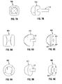
FIGS. 7A and 7B are frontal and side perspective views respectively of a first connector of an incision closure device according to an embodiment of the present disclosure; -
FIGS. 8A and 8B are frontal and side perspective views respectively of a first connector of an incision closure device according to another embodiment of the present disclosure; -
FIG. 8C is a side perspective view of the first connector illustratedFIGS. 8A and 8B shown with pin elements according to an embodiment of the present disclosure; -
FIGS. 9A and 9B are frontal and side perspective views respectively of a first connector of an incision closure device according to yet another embodiment of the present disclosure; -
FIG. 9C is a side perspective view of the first connector illustratedFIGS. 9A and 8B shown with apertures according to an embodiment of the present disclosure; -
FIG. 10 is an exploded view of first and second connectors of an incision closure device according to an embodiment of the present disclosure; -
FIG. 11 is a cross-sectional view of the first and second connector assemblies illustrated inFIG. 10 shown in a deployed configuration according to an embodiment of the present disclosure; -
FIGS. 12A through 12G illustrate a method of incision closure using the incision closure device shown inFIGS. 1 and 2 according to an embodiment of the present disclosure; -
FIGS. 13 and 14 are perspective views of the first and second connector assemblies illustrated inFIGS. 1 and 2 shown in a deployed configuration, according to an embodiment of the present disclosure; -
FIG. 15 is a perspective view of the first and second connector assemblies illustrated inFIGS. 3 and 4 shown with another embodiment of a deployment member in accordance with the present disclosure; -
FIGS. 16A through 16E illustrate a method of incision closure using the incision closure device shown inFIG. 15 according to an embodiment of the present disclosure; and -
FIG. 17 is a flowchart illustrating a method of incision closure according to an embodiment of the present disclosure. - Hereinafter, embodiments of the presently disclosed incision closure device and methods of incision closure using the same will be described with reference to the accompanying drawings. Like reference numerals may refer to similar or identical elements throughout the description of the figures. As shown in the drawings and as used in this description, and as is traditional when referring to relative positioning on an object, the term "proximal" refers to that portion of the device, or component thereof, closer to the user and the term "distal" refers to that portion of the device, or component thereof, farther from the user.
- This description may use the phrases "in an embodiment," "in embodiments," "in some embodiments," or "in other embodiments," which may each refer to one or more of the same or different embodiments in accordance with the present disclosure. For the purposes of this description, a phrase in the form "A/B" means A or B. For the purposes of the description, a phrase in the form "A and/or B" means "(A), (B), or (A and B)". For the purposes of this description, a phrase in the form "at least one of A, B, or C" means "(A), (B), (C), (A and B), (A and C), (B and C), or (A, B and C)".
- As used herein, the phrase "magnetic material" and the term "magnet" generally refer to any material capable of producing a magnetic field. Although it may be convenient for the purposes of this disclosure to refer to a magnet as having distinct north and south magnetic poles, it is to be understood that this is merely a way of referring to the two different ends of a magnet.
- In various embodiments, the presently disclosed incision closure device includes first and second connectors, which are configured to be magnetically attracted to one another, and a delivery and/or deployment member (also referred to herein as a "handle portion") adapted to axially align the first and second connectors to facilitate closure of incisions, e.g., gastric or colonic incisions, or other wounds. Although various methods described hereinbelow are targeted toward closure of gastric or colonic incisions, it is to be understood that methods of incision closure may be used with other procedures.
-
FIGS. 1 and 2 show anincision closure device 100 according to an embodiment of the present disclosure that includes anelongated handle portion 110, afirst connector 120 detachably affixed to the distal end of thehandle portion 110, and asecond connector 130 adapted to be axially moveable along thehandle portion 110. The shape and size of thefirst connector 120 and thesecond connector 130 may be varied from the configurations depicted inFIGS. 1 and 2 . -
Handle portion 110 may be formed of any suitable material, e.g., metal, such as aluminum, or plastic, such as polyethylene, polycarbonate, or polyvinyl chloride (PVC), or combination thereof.Handle portion 110 may be formed as a substantially solid member having a cylindrical or rod-like shape having a length "L", and may have a uniform or substantially uniform diameter "D1" throughout the entire length "L". In embodiments, thehandle portion 110 is formed entirely of a substantially rigid material, such as, for example, metal, synthetic or compound materials. In embodiments, thehandle portion 110 may include a flexible, malleable or shape memory material. The shape and size of thehandle portion 110 may be varied from the configuration depicted inFIGS. 1 and 2 . According to embodiments of the present disclosure, thehandle portion 110, or portions thereof, may have a curved shape, e.g., to facilitate desirable placement and positioning of the first andsecond connectors -
First connector 120 according to various embodiments includes afirst portion 122 and asecond portion 124.First portion 122 is generally formed as a hollow body having an open end with aperipheral edge 127, and may be formed of any suitable material, such as metal or biocompatible plastic or combination thereof.First portion 122 may include material that is resistant to gastric acid and/or other bodily fluids. In embodiments, thefirst portion 122 has a substantially half-spherical or dome-like shape defining aninterior chamber 129 configured to receive one ormore magnets 170 therein, ) and may include one or more separating arms orwalls 121. - Separating
arms 121 may be configured to partition theinterior chamber 129 into a plurality of compartments configured to receive one ormore magnets 170 therein. For example, as shown inFIG. 2 , theinterior chamber 129 of thefirst portion 122 may be configured to contain fourmagnets 170, individually disposed in separate compartments defined by four separatingarms 121. In various embodiments, the separatingarms 121 may be integrally formed with thefirst portion 122, e.g., injection molded, or separately formed and then joined to thefirst portion 122 by a wide variety of adhesive and bonding techniques including soldering. Separatingarms 121, or portions thereof, may be formed of non-magnetic materials. - Although the
first connector 120 illustrated inFIGS. 1 and 2 has a substantially half-sphericalfirst portion 122, it is to be understood that thefirst connector 120 may be formed in various sizes and shapes. In some cases, the particular procedure and/or the size of the incision to be closed may dictate a particular first connector configuration in order to achieve a desired surgical outcome. Some examples of first connector configurations are shown generally as 720, 820, 880, 920, and 980 are shown inFIGS. 7A, 7B, 8A, 8B, 8C, 9A, 9B and 9C . -
Second portion 124 of thefirst connector 120 generally includes anopening 125 formed therein configured to receive thehandle portion 110 therethrough. In some embodiments, thesecond portion 124 of thefirst connector 120 is formed substantially entirely of a suitable magnetic material.Second portion 124 may include any material capable of producing a magnetic field. Examples of magnetic materials that may be used to form thesecond portion 124 include, but are not limited to, NdFeB (Neodymium Iron Boron), AlNiCo (Aluminum Nickel Cobalt), SmCo (Samarium Cobalt), strontium ferrite, and barium ferrite. In some embodiments, thesecond portion 124, or portions thereof, includes one or more non-magnetic materials.Second portion 124 may include any combination of magnetic and non-magnetic materials. In some embodiments, thesecond portion 124 may include paramagnetic materials, e.g., magnesium, molybdenum, lithium and/or tantalum. -
Second connector 130 of the presently disclosedincision closure device 100 includes ahousing 160 configured to be axially moveable along thehandle 110. In embodiments, thehousing 160 has a substantially half-spherical or dome-like shape defining aninterior chamber 169 extending from aperipheral edge 167.Interior chamber 169 according to various embodiments is configured to receive one ormore magnets 140 therein.Second connector 130 may also include acover 180 and asupport member 150 adapted to be slideably moveable along thehandle portion 110. In embodiments, the one ormore magnets 140 each have a substantially spherical shape. Cover 180 generally includes anopening 181 formed therein configured to receive thehandle portion 110 therethrough. Cover 180 may also include one ormore apertures 182 formed therethrough. -
Housing 160 generally includes aninner surface 161 and anouter surface 162, and may be formed to accommodate various number, sizes and shapes ofmagnets 140.Housing 160 includes anopening 164 formed therein configured to receive thehandle portion 110 therethrough.Housing 160 may be formed of any suitable material, such as metal, biocompatible plastic, or combination thereof. In embodiments, thehousing 160 includes a recessedwall portion 166 spaced from theperipheral edge 167 of thehousing 160 and configured to receive aperipheral edge area 184 of thecover 180 therein. Recessedwall portion 166 may be provided with an adhesive film (not shown) or other material for bonding or otherwise securing thecover 180 to thehousing 160. In embodiments where thehousing 160 and thecover 180 are formed of thermoplastic, theperipheral edge area 184 of thecover 180 and the recessedwall portion 166 of thehousing 160 may be heat welded together. -
Support member 150 according to various embodiments includes acollar portion 155 defining anopening 156, which is advantageously dimensioned to receive thehandle portion 110 therethrough. In embodiments, thesupport member 150 includes one or more separating arms orwalls 151 extending generally radially outward from thecollar portion 155 toward thehousing 160. In an embodiment, four, substantially equallength separating arms 151 are each connected to a separate respective portion of thehousing 160. For example, each separatingarm 151 may be connected to a separate respective portion of theinner surface 161 of thehousing 160. As shown inFIG. 1 , theinterior chamber 169 of thehousing 160 may be configured to contain fourmagnets 140, e.g., individually disposed in separate compartments defined by four separatingarms 151. Separatingarms 151, or portions thereof, may be formed of non-magnetic materials. -
Second connector 130 may be provided with one ormore pin elements 153 configured to extend distally beyond theperipheral edge 167 of thehousing 160 toward thefirst connector 120.Pin elements 153 are generally arranged to align with theapertures 182 in thecover 180, and may extend substantially perpendicular to adistal surface 152 of the separatingarms 151.Pin elements 153 may extend substantially parallel to a longitudinal axis of thehandle portion 110. In embodiments, thepin elements 153 are attached to the separatingarms 151.Pin elements 153 are advantageously shaped and dimensioned to penetrate into body tissue. In an embodiment of the presently disclosed incision closure device, a first connector (e.g., 980 shown inFIG. 9C ) includes apertures configured to receive at least a portion of thepin elements 153.Pin elements 153 may be formed of any suitable material, e.g., metal or plastic. The thickness of thecover 180 may be varied depending on various factors, such as, for example, the length of thepin elements 153, materials used to form thecover 180 and thepin elements 153, tissue, characteristics, and/or incision size or other incision characteristics. It is to be understood that the number, position, length, and shape of thepin elements 153 may be varied from the configurations depicted inFIGS. 1 and 2 . Although fourpin elements 153 are illustrated inFIGS. 1 and 2 , it is be understood that thesecond connector 130 may include various number of pin elements. -
Support member 150 may be formed of any suitable material. In some embodiments, thesupport member 150 may be formed of a substantially rigid material, such as metal (e.g., stainless steel) or plastic (e.g., polyvinyl chloride (PVC), polystyrenes, polyurethanes, thermoplastic elastomers, and acrylics). - Procedures for the delivery and deployment of the first and
second connectors incision closure device 100 are described later in this disclosure with reference toFIGS. 12A through 12G . -
FIGS. 3 and 4 show anincision closure device 300 according to an embodiment of the present disclosure that includes anelongated handle portion 310, afirst connector 320 detachably affixed to the distal end of thehandle portion 310, and asecond connector 330 adapted to be axially moveable along thehandle portion 310.Handle portion 310 may be formed of any suitable material, such as metal or plastic or combination thereof.Handle portion 310 is similar to thehandle portion 110 shown inFIGS. 1 and 2 and further description thereof is omitted in the interests of brevity. -
First connector 320 includes afirst portion 322 and asecond portion 324.First portion 322 is generally formed as a hollow body having an open end with aperipheral edge 367, and may be formed of any suitable material, such as metal or biocompatible plastic or combination thereof. In an embodiment of the presently disclosedincision closure device 300, thefirst connector 320 is substantially the same as thefirst connector 120 illustrated inFIGS. 1 and 2 . For example, in one instance, the first andsecond portions first connector 320 are substantially the same, respectively, as the first andsecond portions FIGS. 1 and 2 . - In embodiments, the
first portion 322 has a substantially half-spherical or dome-like shape defining aninterior chamber 329 configured to receive one or more magnets (e.g., fourmagnets 350 shown inFIG. 4 ) therein, and may include one or more separating arms orwalls 321. Separatingarms 321 may be configured to partition theinterior chamber 329 into a plurality of compartments configured to receive one ormore magnets 350 therein.Second portion 324 of thefirst connector 320 generally includes anopening 325 formed therein configured to receive thehandle portion 310 therethrough.Second portion 324 may be formed from magnetic materials, non-magnetic materials, or combinations thereof. -
Second connector 330 according to various embodiments includes an axiallymoveable housing 360 defining aninterior chamber 369 configured to receive one or more magnets (e.g., fourmagnets 340 shown inFIG. 4 ) therein, and a wall portion or cover 370 adapted to be slideably moveable along thehandle portion 310. In an embodiment of the presently disclosedincision closure device 300, themagnets 340 are substantially the same as themagnets 140 shown inFIGS. 1 and 2 . - In embodiments, the
housing 360 has a substantially half-spherical or dome-like shape.Housing 360 may be formed of any suitable material, such as metal or biocompatible plastic or combination thereof.Housing 360 includes anopening 364 formed therein configured to receive thehandle portion 110 therethrough. In embodiments, thehousing 360 includes a recessedwall portion 366 spaced from aperipheral edge 367 of thehousing 360 and configured to receive aperipheral edge area 384 of thewall portion 170 therein. Recessedwall portion 366 may be provided with an adhesive film (not shown) or other material for bonding or otherwise securing thecover wall portion 170 to thehousing 360. -
Wall portion 370 generally includes anopening 371 formed therein configured to receive thehandle portion 310 therethrough. In some embodiments, thewall portion 370 includes at least threepin elements 373 extending forwardly toward thefirst connector 320.Pin elements 373 may extend substantially perpendicular to adistal surface 372 of thewall portion 370.Pin elements 373 are advantageously shaped and dimensioned to penetrate into body tissue. Although sixpin elements 373 are illustrated inFIG. 4 , it is be understood that thewall portion 370 may include various number of pin elements and/or pin shapes. -
FIGS. 5 and 6 show anincision closure device 500 according to an embodiment of the present disclosure that includes anelongated handle portion 510, afirst connector 520 detachably affixed to the distal end of thehandle portion 510, asecond connector 530 adapted to be axially moveable along thehandle portion 510.Handle portion 510 may be formed of any suitable material, such as metal or plastic or combination thereof.Handle portion 510 is similar to thehandle portion 110 shown inFIGS. 1 and 2 and further description thereof is omitted in the interests of brevity. - The
first connector 520 includes afirst portion 522 and asecond portion 524. In embodiments, thesecond portion 524 of thefirst connector 520 is formed substantially entirely of a magnetic material. In embodiments, thesecond portion 524 includes one or more non-magnetic materials. For example, non-magnetic materials may be used to partition thesecond portion 524 into two or more separate regions of magnetic material.Second portion 524 generally includes anopening 525 formed therein configured to receive thehandle portion 510 therethrough.First portion 522 of thefirst connector 520 may be advantageously shaped and dimensioned to house thesecond portion 524 therein. For example, as shown inFIG. 6 , thefirst portion 522 may define a cavity orchamber 529 configured to receive thesecond portion 524 therein.Chamber 529, or portions thereof, may be provided with an adhesive film (not shown) or other material for bonding thesecond portion 524 to thefirst portion 522. -
Second connector 530 includes an axiallymoveable housing 560 defining an interior chamber 569 configured to receive one ormore magnets 540 therein, acover 580, and asupport member 550 adapted to be slideably moveable along thehandle portion 510. Cover 580 is arranged between thehousing 560 and thesecond portion 524 of thefirst connector 520.Housing 560 generally includes aninner surface 561 and anouter surface 562, and may be formed to accommodate various number, sizes and shapes ofmagnets 540. In an embodiment of the presently disclosedincision closure 500, thehousing 560 is substantially the same as thehousing 160 shown inFIGS. 1 and 2 . For example, in one instance, thesupport member 550 of thesecond connector 530 is substantially the same as thesupport member 150 shown inFIGS. 1 and 2 . -
Support member 550 according to various embodiments includes acollar portion 555 defining anopening 556 configured to receive thehandle portion 110 therethrough, and may include one or more separating arms orwalls 551 extending generally radially outward from thecollar portion 555 toward thehousing 560. In embodiments, a plurality of substantially equallength separating arms 551 are each connected to a separate respective portion of theinner surface 561 of thehousing 560. -
Second connector 130 may be provided with one ormore pin elements 553 configured to extend distally beyond theperipheral edge 567 of thehousing 560 toward thefirst connector 520. In embodiments, thepin elements 553 are coupled to the separatingarms 151. - Cover 580 includes an
opening 581 formed therein that is advantageously dimensioned to receive thehandle portion 510. Cover 580 may also include one ormore apertures 582 configured to receive thepin elements 553 therethrough. In embodiments, the pin elements 553 a nd theapertures 582 may be designed and configured to be interlocking. Although the distal and proximal surfaces of thecover 580 shown inFIGS. 5 and 6 are generally flat, it is to be understood that the distal and proximal surfaces ofcover 580 according to various embodiments may be curved or may include a combination of flat, sloped or curved portions. The thickness of thecover 580 may be varied depending on various factors, such as, for example, the length of thepin elements 553, materials used to form thecover 580 and thepin elements 553, tissue, characteristics, and/or incision size or other incision characteristics. - In embodiments, the
housing 560 has a substantially half-spherical or dome-like shape.Housing 560 may be formed of any suitable material, such as metal or biocompatible plastic or combination thereof.Housing 560 includes anopening 564 formed therein configured to receive thehandle portion 110 therethrough. In embodiments, thehousing 560 includes a recessedwall portion 566 configured to receive aperipheral edge area 584 of thecover 580 therein. Recessedwall portion 566 may be provided with an adhesive film (not shown) or other material for bonding thecover wall portion 170 to thehousing 360. - The shape and size of the
first connector 520 and thesecond connector 530 may be varied from the configurations depicted inFIGS. 5 and 6 . For example, in lieu of thefirst connector 520, the presently disclosed incision closure device may be configured with one of the first connector embodiments (e.g., 720, 820, 880, 920, or 980) shown inFIGS. 7A through 9C . As shown inFIG. 8C , the presently disclosed first connector may include one ormore pin elements 882.Pin elements 882 are similar thepin elements 373 shown inFIG. 4 and further description thereof is omitted in the interests of brevity. As shown inFIG. 9C , the presently disclosed first connector may include one ormore apertures 982, which may be configured to receive pin elements (e.g., 553 shown inFIG. 4 ) therein. According to various embodiments, the presently disclosed first connector may include one or more pin elements and/or apertures, and the presently disclosed second connector may include one or more pin elements and/or apertures. -
FIGS. 10 and 11 show anincision closure device 1000 according to an embodiment of the present disclosure that includes afirst connector 1020 configured to be detachably affixed to the distal end of a handle portion (e.g., 710 shown inFIG. 15 ) and asecond connector 1030 adapted to be axially moveable along the handle portion. InFIGS. 10 and 11 , the first andsecond connector assemblies second connectors incision closure device 1000 are described later in this disclosure with reference toFIGS. 12A through 12G andFIGS. 16A through 16E . -
FIG. 10 is an exploded view of thefirst connector assembly 1020 and thesecond connector assembly 1030 of the presently disclosedincision closure device 1000. As shown inFIG. 10 , thefirst connector assembly 1020 may include afirst cap 1022, afirst member 1024 including anopening 1024a defined therein, and afirst housing portion 1026 defining aninterior chamber 1029 configured to receive thefirst member 1024 therein. -
First housing portion 1026 according to various embodiments includes aconnector portion 1028 extending into thechamber 1029. In embodiments, theconnector portion 1028 defines a recess (e.g., 1026a shown inFIG. 11 ) configured to receive a distal end of a handle portion (e.g., 710 shown inFIG. 15 ) therein. As cooperatively shown inFIGS. 10 and 11 , theconnector portion 1028 of thehousing portion 1026 may be configured to fit within theopening 1024a of thefirst member 1024 when thefirst member 1024 and thehousing portion 1026 are coupled together. - In embodiments, the
second connector assembly 1030 includes asecond cap 1032, asecond member 1034 including anopening 1034a defined therein, and asecond housing portion 1036 defining an interior chamber 1039 (shown inFIG. 11 ) configured to receive thesecond member 1034 therein. -
First cap 1022 of thefirst connector 1020 and thesecond cap 1032 of thesecond connector assembly 1030 may be formed of any suitable material, such as metal or biocompatible plastic or combination thereof.Second cap 1032 generally includes anopening 1032a formed therein configured to receive a handle portion (not shown) therethrough. As cooperatively shown inFIGS. 10 and 11 , thefirst cap 1022 includes aflange portion 1021 configured to engage an innerperipheral edge 1027 of thefirst housing portion 1026, and thesecond cap 1032 includes aflange portion 1031 configured to engage an innerperipheral edge 1035 of thesecond housing portion 1036. The shape and size of thefirst cap 1022 and thesecond cap 1032 may be varied from the configurations depicted inFIGS. 10 and 11 . - In embodiments, each of the first and
second members second members second members - First and
second members FIG. 10 each have a generally annular body including a distal surface, which may be regarded as corresponding to its north pole "N", a proximal surface, which may be regarded as corresponding to its south pole "S", and an outer diameter wall. In embodiments, the outer diameter wall of thefirst member 1024 is advantageously dimensioned to fit within theinterior chamber 1029 of thefirst housing portion 1026 of thefirst connector assembly 1020. In embodiments, the outer diameter wall of thesecond member 1034 is advantageously dimensioned to fit within theinterior chamber 1039 of thesecond housing portion 1036 of thesecond connector assembly 1030. -
Second housing portion 1036 may include at least threepin elements 1037 extending forwardly toward thefirst connector 1020.Pin elements 1037 may extend substantially perpendicular to a surface of thesecond housing portion 1036.Pin elements 1037 are advantageously shaped and dimensioned to penetrate into body tissue. Although sixpin elements 1037 are illustrated inFIG. 10 , it is be understood that thesecond housing portion 1036 may include various number of pin elements, such as three pin elements to establish a plane. -
FIG. 11 is a cross-sectional view of the first and second connector assemblies illustrated inFIG. 10 shown in a deployed configuration, according to an embodiment of the present disclosure. The magnetic attraction between opposite poles of the axially-aligned first andsecond connector assemblies FIG. 10 ) of the firstmagnetic member 1024 and the distal end (e.g., "N" shown inFIG. 10 ) of the secondmagnetic member 1034 maintains the first andsecond connector assemblies - The amount of compression force exerted by the axially-aligned first and
second connector assemblies second members first housing portion 1026 of thefirst connector assembly 1020, the materials (magnetic and/or non-magnetic) used to form thesecond housing portion 1036 of thesecond connector assembly 1030, and/or tissue characteristics, e.g., cellular density. -
FIGS. 12A through 12G illustrate a method of incision closure using the presently disclosedincision closure device 100 shown inFIGS. 1 and 2 ). It is to be understood, however, that other incision closure device embodiments may also be used (e.g., 300, 500 and 1000 shown inFIGS. 3 ,5 and10 , respectively). As shown inFIGS. 12C through 12F , anouter sleeve member 105, configured to slideably engage thehandle portion 110, may be used to exert a biasing force against thesecond connector 130, e.g., to move thesecond connector 130 along thehandle portion 110 toward the surgical access site "S". In embodiments, theouter sleeve member 105 includes a hollow cylindrical body having an inner surface with an inner diameter, which is larger than the outer diameter of thehandle portion 110.Outer sleeve member 105 may include a grip portion (not shown) configured for grasping by the surgeon. - Referring to
FIG. 12A , thefirst connector 120 at the distal end of thehandle portion 110 is delivered to a surgical access site "S", e.g., near an outer or proximal surface of tissue "T", and the surgeon aligns thefirst connector 120 and/or thehandle portion 110 with the incision or opening "O" in the tissue "T". For example, the surgeon may position theincision closure device 100 relative to the surgical access site "S" such that a longitudinal axis "A" of thehandle portion 110 is centrally aligned with the opening "O" in the tissue "T". - After the
first connector 120 is aligned with the opening, the surgeon moves the handle portion 110 a first length "L1" in a first direction (also referred to herein as a distal or forward direction), as indicated by the left arrow inFIG. 12B , so that thefirst connector 120 is moved through the opening "O" to a position near the inner or distal surface of tissue "T", e.g., close to the opening "O". - As shown in
FIGS. 12C and 12D , the surgeon may use the presently disclosedouter sleeve member 105 to move thesecond connector 130 in a forward direction, as indicated by the left arrows inFIGS. 12C and 12D , along thehandle portion 110. As shown inFIG. 12D , thesecond connector 130 may be moved a length "L2" along thehandle portion 110 to place thesecond connector 130 in contact with the proximal surface of the tissue "T". - After the
second connector 130 is placed in contact with the proximal surface of the tissue "T", theouter sleeve member 105 may be moved in a second direction (also referred to herein as a proximal direction), as indicated by the right arrows inFIGS. 12E and 12F , to partially, or entirely, remove theouter sleeve member 105 from thehandle portion 110. - While the
second connector 130 is in contact with the proximal surface of tissue "T", thehandle portion 110 is moved in the second direction, as indicated by the right arrows inFIG. 12G , to move thefirst connector 120 toward the distal surface of the tissue "T". In embodiments, by moving the handle portion 110 a third distance "L3" in the second direction, thefirst connector 120 is brought into contact with the distal surface of the tissue "T". Magnetic attraction between the presently disclosed first andsecond connectors incision closure device 100 in intimate contact with the tissue "T". - While the axially-aligned first and
second connectors handle portion 110 is retracted free of the first andsecond connectors FIG. 12G. FIGS. 13 and 14 show the deployed first andsecond connectors incision closure device 100. - According to another embodiment of the present disclosure, an incision closure device, shown generally as 301 in
FIG. 15 , includes thefirst connector 320 and thesecond connector 330 illustrated inFIGS. 3 and 4 , and a delivery and/or deployment member 710 (also referred to herein as a "handle portion"). In embodiments, thehandle portion 710 may be formed of metal, synthetic or compound materials. The shape and size of thehandle portion 710 may be varied from the configuration depicted inFIG. 15 . - In embodiments, the
handle portion 710 includes afirst section 713 having adistal end 711, and asecond section 715 having adistal end 714 disposed adjacent aproximal end 712 of thefirst section 713. As shown inFIG. 15 , thefirst section 713 has a first length "L5" and a first diameter "D2", and thesecond section 715 has a second length "L6" and a second diameter "D3", where "D3" > "D2". In embodiments, the first diameter "D2" of thehandle portion 710 may be the same as the diameter "D1" of thehandle portion 110 shown inFIG. 1 . -
FIGS. 16A through 16E illustrate a method of incision closure using the presently disclosedincision closure device 301 shown inFIG. 15 . In embodiments, in an initial step, thesecond connector 330 is axially positioned on thefirst section 713 of thehandle portion 710 adjacent thedistal end 714 of thesecond section 715 of thehandle portion 710, and thesecond connector 330 is detachably affixed to thedistal end 711 of thefirst section 713, as cooperatively shown inFIGS. 15 and 16A . - Referring to
FIG. 16A , thefirst connector 120 at the distal end 713a of thehandle portion 110 is delivered to a surgical access site "S", e.g., near an outer or proximal surface of tissue "T", and the surgeon aligns thefirst connector 120 and/or thehandle portion 110 with the incision or opening "O" in the tissue "T". For example, the surgeon may position theincision closure device 100 relative to the surgical access site "S" such that a longitudinal axis "A" of thehandle portion 110 is centrally aligned with the opening "O" in the tissue "T". - After the
first connector 120 is aligned with the opening, the surgeon moves the handle portion 110 a first length "L1" in a first direction (also referred to herein as a distal or forward direction), as indicated by the left arrow inFIG. 12B , so that thefirst connector 120 is moved through the opening "O" to a position near the inner or distal surface of tissue "T", e.g., in close proximity to the opening "O". - Hereinafter, a method of incision closure, in accordance with the present disclosure, is described with reference to
FIG. 17 . It is to be understood that the steps of the method provided herein may be performed in combination and in a different order than presented herein without departing from the scope of the disclosure. -
FIG. 17 is a flowchart illustrating a method of incision closure according to an embodiment of the present disclosure. Instep 1710, an incision closure device (e.g., 301 shown inFIG. 15 ) is positioned relative to a surgical access site (e.g., "S" shown inFIG. 16A ). The incision closure device includes a first connector (e.g., 320 shown inFIG. 15 ), a second connector (e.g., 330 shown inFIG. 15 ) and a deployment member (e.g., 710 shown inFIG. 15 ). The first connector is detachably mounted on the distal end (e.g., 713a shown inFIG. 15 ) of the deployment member. The second connector is slideably mounted on the deployment member proximal to the first connector. The first and second connectors are magnetically attracted to one another. - In
step 1720, the deployment member is moved a first distance in a first direction (e.g., as indicated by the left arrows inFIG. 16A ), causing the first connector to pass through an incision (e.g., "O" shown inFIG. 16A ) at the surgical access site (e.g., "S" shown inFIG. 16A ). - In
step 1730, the deployment member is moved a second distance in the first direction, placing the second connector in contact with tissue (e.g., "T" shown inFIG. 16C ). - In
step 1740, the deployment member is moved a third distance in a second direction (e.g., as indicated by the right arrows inFIG. 16D ) that is opposite to the first direction, placing the first connector in contact with tissue. In embodiments, the magnetic attraction between the magnets (e.g., 170 shown inFIG. 2 ) of the first connector and the magnets (e.g., 140 shown inFIG. 2 ) of the second connector maintains the first and second connectors in intimate contact with tissue (e.g., "T" shown inFIG. 16E ) at the surgical access site, forming a secure incision closure. - In
step 1750, the deployment member is moved a fourth distance in the second direction, removing the deployment member from the surgical access site. - In various embodiments, the presently disclosed incision closure device includes first and second connectors, which are configured to be magnetically attracted to one another, and a delivery and/or deployment member (also referred to herein as a "handle portion") adapted to axially align the first and second connectors to facilitate closure of incisions or other wounds. In various embodiments of the presently disclosed incision closure device and methods of incision closure using the same, the magnetic attraction between the axially-aligned first and second connectors may help to facilitate the formation of a reliable, secure incision closure.
- The presently disclosed first connector and/or the second connector may be provided with one or more pin elements configured to penetrate tissue, which may help to facilitate the formation of a reliable, secure incision closure. In embodiments, the first connector and/or the second connector may include one or more apertures configured to receive the pin elements therein, which may enhance the reliability of the incision closure, e.g., by inhibiting lateral movement of the first connector relative to the second connector.
- Although embodiments have been described in detail with reference to the accompanying drawings for the purpose of illustration and description, it is to be understood that the inventive processes and apparatus are not to be construed as limited thereby. It will be apparent to those of ordinary skill in the art that various modifications to the foregoing embodiments may be made without departing from the scope of the disclosure.
Claims (17)
- An incision closure device, comprising:an elongated handle portion including a distal end;a first connector detachably affixed to the distal end of the handle portion; anda second connector adapted to be axially moveable along the handle portion,wherein the first and second connectors are magnetically attracted to one another.
- The incision closure device of claim 1, wherein the first connector includes a first portion formed as a hollow body having an open end with a peripheral edge, and a second portion disposed over the open end.
- The incision closure device of claim 1 or 2, wherein the first portion has a substantially half-spherical shape defining an interior chamber configured to receive one or more magnets therein.
- The incision closure device of claim 3, wherein the first portion includes at least one separating wall configured to separate the interior chamber of the first portion into a plurality of compartments configured to receive the one or more magnets therein.
- The incision closure device of any preceding claim, wherein the second connector includes a housing defining an interior chamber configured to receive one or more magnets therein.
- The incision closure device of claim 5, wherein the housing includes an opening formed therein configured to receive the handle portion therethrough.
- The incision closure device of claim 6, wherein the housing further includes a support member, the support member including a collar portion defining an opening configured to receive the handle portion therethrough.
- The incision closure device of claim 7, wherein the support member further includes a plurality of separating arms extending generally radially outward from the collar portion toward the housing.
- The incision closure device of claim 8, wherein each of the separating arms includes at least one non-magnetic material.
- The incision closure device of claim 8 or claim 9, wherein each of the separating arms includes at least one pin element configured to penetrate tissue.
- The incision closure device of claim 10, wherein the second portion each of the first connector includes at least one aperture configured to receive the at least one pin element therein.
- The incision closure device of any preceding claim, wherein the handle portion has a first section having a first diameter, and a second section disposed proximal to the first section, the second section having a second diameter larger than the first diameter.
- The incision closure device of claim 12, wherein the first connector is detachably affixed to a distal end of the first section of the handle portion.
- The incision closure device of any preceding claim, wherein the handle portion includes at least one of a flexible material, a malleable material, or a shape memory material.
- The incision closure device of claim 14, wherein the handle portion has a length and a substantially uniform diameter throughout the length.
- An incision closure device, comprising:a first connector capable of producing a magnetic field;a second connector capable of producing a magnetic field; anda handle portion including a first section having a first diameter and a second section disposed proximal to the first section, the second section having a second diameter larger than the first diameter,wherein the first connector is configured to be detachably affixed to a distal end of the first section of the handle portion.
- The incision closure device of claim 16, wherein the second connector is positionable adjacent to a distal end of the second section of the handle portion, and/or the incision closure device of claim 16, wherein at least one of the first connector and the second connector includes at least one non-magnetic material.
Applications Claiming Priority (2)
| Application Number | Priority Date | Filing Date | Title |
|---|---|---|---|
| US16992709P | 2009-04-16 | 2009-04-16 | |
| US12/721,651 US9402605B2 (en) | 2009-04-16 | 2010-03-11 | Magnetically retained incision closure devices and methods of incision closure using same |
Publications (2)
| Publication Number | Publication Date |
|---|---|
| EP2241261A1 true EP2241261A1 (en) | 2010-10-20 |
| EP2241261B1 EP2241261B1 (en) | 2018-01-10 |
Family
ID=42470546
Family Applications (1)
| Application Number | Title | Priority Date | Filing Date |
|---|---|---|---|
| EP10250786.0A Not-in-force EP2241261B1 (en) | 2009-04-16 | 2010-04-16 | Magnetically retained incision closure devices |
Country Status (4)
| Country | Link |
|---|---|
| US (2) | US9402605B2 (en) |
| EP (1) | EP2241261B1 (en) |
| AU (1) | AU2010201123A1 (en) |
| CA (1) | CA2698016A1 (en) |
Cited By (1)
| Publication number | Priority date | Publication date | Assignee | Title |
|---|---|---|---|---|
| EP2978379A4 (en) * | 2013-03-27 | 2016-11-02 | Freudenberg Medical Llc | Septal perforation prosthesis |
Families Citing this family (22)
| Publication number | Priority date | Publication date | Assignee | Title |
|---|---|---|---|---|
| EP1909655A2 (en) | 2005-06-20 | 2008-04-16 | Sutura, Inc. | Method and apparatus for applying a knot to a suture |
| JP5411125B2 (en) | 2007-03-29 | 2014-02-12 | ノーブルズ メディカル テクノロジーズ、インコーポレイテッド | Suture device and system for closing a patent foramen ovale |
| EP2291125B1 (en) | 2008-05-09 | 2021-04-21 | Nobles Medical Technologies, Inc. | Suturing devices for suturing an anatomic valve |
| JP2012500098A (en) | 2008-08-19 | 2012-01-05 | ウィルソン−クック・メディカル・インコーポレーテッド | Instrument for excision of lymph nodes or attachment to tissue during transluminal procedures |
| US8192461B2 (en) | 2008-09-11 | 2012-06-05 | Cook Medical Technologies Llc | Methods for facilitating closure of a bodily opening using one or more tacking devices |
| WO2010068589A1 (en) | 2008-12-09 | 2010-06-17 | Wilson-Cook Medical Inc. | Retractable tacking device |
| CA2747233C (en) | 2008-12-19 | 2014-08-12 | John A. Karpiel | Clip devices and methods of delivery and deployment |
| US9402605B2 (en) | 2009-04-16 | 2016-08-02 | Covidien Lp | Magnetically retained incision closure devices and methods of incision closure using same |
| AU2010254151B2 (en) | 2009-05-28 | 2013-11-28 | Cook Medical Technologies Llc | Tacking device and methods of deployment |
| EP3644194B1 (en) | 2011-04-15 | 2022-12-07 | Heartstitch, Inc. | Suturing devices for suturing an anatomic valve |
| EP2852332B1 (en) | 2012-05-11 | 2019-06-26 | Heartstitch, Inc. | Suturing devices for suturing an anatomic structure |
| WO2014205269A2 (en) * | 2013-06-20 | 2014-12-24 | Curaseal Inc. | Enteroatmospheric fistula treatment devices |
| JP6431534B2 (en) | 2013-07-02 | 2018-11-28 | メッド − ベンチャー インベストメンツ、エルエルシー | Suture device and method for suturing anatomic tissue |
| US9486217B2 (en) | 2013-09-23 | 2016-11-08 | Moustafa Moustafa | Magnetic wound closure device and method of use |
| EP3079602B1 (en) | 2013-12-06 | 2020-01-22 | Med-venture Investments, LLC | Suturing apparatuses |
| US10178993B2 (en) | 2014-07-11 | 2019-01-15 | Cardio Medical Solutions, Inc. | Device and method for assisting end-to-side anastomosis |
| WO2017180092A1 (en) | 2016-04-11 | 2017-10-19 | Nobles Medical Technologies Ii, Inc. | Suture spools for tissue suturing device |
| US10729439B2 (en) | 2016-12-16 | 2020-08-04 | Moustafa Moustafa | Magnetic wound closure device and method of use |
| US9693776B1 (en) | 2016-12-16 | 2017-07-04 | Moustafa Moustafa | Magnetic wound closure device and method of use |
| US11839370B2 (en) | 2017-06-19 | 2023-12-12 | Heartstitch, Inc. | Suturing devices and methods for suturing an opening in the apex of the heart |
| EP4115818A3 (en) | 2017-06-19 | 2023-04-05 | Heartstitch, Inc. | Suturing systems and methods for suturing body tissue |
| WO2019035095A1 (en) | 2017-08-18 | 2019-02-21 | Nobles Medical Technologies Ii, Inc. | Apparatus for applying a knot to a suture |
Citations (6)
| Publication number | Priority date | Publication date | Assignee | Title |
|---|---|---|---|---|
| US4338937A (en) * | 1980-12-05 | 1982-07-13 | Lerman Sheldon H | Mechanical continent ileostomy or colostomy |
| US5342393A (en) * | 1992-08-27 | 1994-08-30 | Duke University | Method and device for vascular repair |
| US20030055455A1 (en) * | 2001-09-20 | 2003-03-20 | Scimed Life Systems, Inc. | Method and apparatus for treating septal defects |
| WO2004105693A2 (en) * | 2003-05-23 | 2004-12-09 | Ventrica, Inc. | Components, systems and methods for forming anastomoses using magnetism or other coupling means |
| WO2007016261A2 (en) * | 2005-07-29 | 2007-02-08 | Cvdevices, Llc | Magnetic devices and methods for septal occlusion |
| WO2009029228A2 (en) * | 2007-08-27 | 2009-03-05 | Torax Medical, Inc. | Magnetic gastric band or the like, and related methods |
Family Cites Families (23)
| Publication number | Priority date | Publication date | Assignee | Title |
|---|---|---|---|---|
| US3986493A (en) * | 1975-07-28 | 1976-10-19 | Hendren Iii William Hardy | Electromagnetic bougienage method |
| NL7906691A (en) | 1979-09-07 | 1981-03-10 | Jansen Anton | MEDICAL DEVICE FOR COUPLING TWO Bowel Sections, Auxiliary Device For Using It And Method Of Laying A Gut Knot Using This Device. |
| US4917114A (en) * | 1986-10-17 | 1990-04-17 | United States Surgical Corporation | Surgical fastener and surgical stapling apparatus |
| US5336233A (en) * | 1989-01-26 | 1994-08-09 | Chen Fusen H | Anastomotic device |
| GR1002290B (en) | 1991-06-03 | 1996-05-02 | Ethicon Inc. | Absorbable anastomosic fastener means. |
| US5376098A (en) | 1992-10-09 | 1994-12-27 | United States Surgical Corporation | Fragmentable anastomosis ring applier |
| US5346501A (en) * | 1993-02-05 | 1994-09-13 | Ethicon, Inc. | Laparoscopic absorbable anastomosic fastener and means for applying |
| US6068637A (en) * | 1995-10-03 | 2000-05-30 | Cedar Sinai Medical Center | Method and devices for performing vascular anastomosis |
| FR2760627A1 (en) | 1997-03-14 | 1998-09-18 | Jean Pierre Pozzi | Suturing system for human tissue sections or similar |
| US6352543B1 (en) * | 2000-04-29 | 2002-03-05 | Ventrica, Inc. | Methods for forming anastomoses using magnetic force |
| JP3901421B2 (en) * | 1999-08-19 | 2007-04-04 | 有限会社 パックス オプティカ ジャパン | Organ anastomosis device |
| US7232449B2 (en) * | 2000-04-29 | 2007-06-19 | Medtronic, Inc. | Components, systems and methods for forming anastomoses using magnetism or other coupling means |
| US7909837B2 (en) * | 2000-12-13 | 2011-03-22 | Medtronic, Inc. | Methods, devices and systems for forming magnetic anastomoses |
| US20020143347A1 (en) * | 2000-12-13 | 2002-10-03 | Ventrica, Inc. | Extravascular anastomotic components and methods for forming vascular anastomoses |
| US6503259B2 (en) * | 2000-12-27 | 2003-01-07 | Ethicon, Inc. | Expandable anastomotic device |
| JP3930757B2 (en) | 2002-04-10 | 2007-06-13 | 有限会社 パックス オプティカ ジャパン | Organ anastomosis device |
| US8142454B2 (en) * | 2004-09-29 | 2012-03-27 | The Regents Of The University Of California, San Francisco | Apparatus and method for magnetic alteration of anatomical features |
| US20060271107A1 (en) * | 2004-09-29 | 2006-11-30 | Harrison Michael R | Apparatus and methods for magnetic alteration of anatomical features |
| US8162974B2 (en) * | 2006-02-02 | 2012-04-24 | Boston Scientific Scimed, Inc. | Occlusion apparatus, system, and method |
| US20080114384A1 (en) * | 2006-11-10 | 2008-05-15 | Wilson-Cook Medical Inc. | Ring magnets for surgical procedures |
| US20080200934A1 (en) * | 2007-02-15 | 2008-08-21 | Fox William D | Surgical devices and methods using magnetic force to form an anastomosis |
| US8506516B2 (en) | 2007-05-29 | 2013-08-13 | Cvdevices, Llc | Devices, systems, and methods for achieving magnetic gastric bypass |
| US9402605B2 (en) | 2009-04-16 | 2016-08-02 | Covidien Lp | Magnetically retained incision closure devices and methods of incision closure using same |
-
2010
- 2010-03-11 US US12/721,651 patent/US9402605B2/en not_active Expired - Fee Related
- 2010-03-22 AU AU2010201123A patent/AU2010201123A1/en not_active Abandoned
- 2010-03-30 CA CA2698016A patent/CA2698016A1/en not_active Abandoned
- 2010-04-16 EP EP10250786.0A patent/EP2241261B1/en not_active Not-in-force
-
2016
- 2016-06-27 US US15/193,200 patent/US10039537B2/en not_active Expired - Fee Related
Patent Citations (6)
| Publication number | Priority date | Publication date | Assignee | Title |
|---|---|---|---|---|
| US4338937A (en) * | 1980-12-05 | 1982-07-13 | Lerman Sheldon H | Mechanical continent ileostomy or colostomy |
| US5342393A (en) * | 1992-08-27 | 1994-08-30 | Duke University | Method and device for vascular repair |
| US20030055455A1 (en) * | 2001-09-20 | 2003-03-20 | Scimed Life Systems, Inc. | Method and apparatus for treating septal defects |
| WO2004105693A2 (en) * | 2003-05-23 | 2004-12-09 | Ventrica, Inc. | Components, systems and methods for forming anastomoses using magnetism or other coupling means |
| WO2007016261A2 (en) * | 2005-07-29 | 2007-02-08 | Cvdevices, Llc | Magnetic devices and methods for septal occlusion |
| WO2009029228A2 (en) * | 2007-08-27 | 2009-03-05 | Torax Medical, Inc. | Magnetic gastric band or the like, and related methods |
Cited By (1)
| Publication number | Priority date | Publication date | Assignee | Title |
|---|---|---|---|---|
| EP2978379A4 (en) * | 2013-03-27 | 2016-11-02 | Freudenberg Medical Llc | Septal perforation prosthesis |
Also Published As
| Publication number | Publication date |
|---|---|
| AU2010201123A1 (en) | 2010-11-04 |
| US20100268270A1 (en) | 2010-10-21 |
| US9402605B2 (en) | 2016-08-02 |
| EP2241261B1 (en) | 2018-01-10 |
| CA2698016A1 (en) | 2010-10-16 |
| US10039537B2 (en) | 2018-08-07 |
| US20160302781A1 (en) | 2016-10-20 |
Similar Documents
| Publication | Publication Date | Title |
|---|---|---|
| US10039537B2 (en) | Magnetically retained incision closure devices and methods of incision closure using same | |
| US11344308B2 (en) | Modular magnetic devices for use in creating tissue anastomosis | |
| JP4961534B2 (en) | Medical holder and method of using medical holder | |
| US8828031B2 (en) | Apparatus for forming an anastomosis | |
| US8685046B2 (en) | Magnetic compression anastomosis device | |
| US8532747B2 (en) | Biopsy marker delivery device | |
| US20110284014A1 (en) | Medical Devices That Include Removable Magnet Units and Related Methods | |
| US20090078736A1 (en) | Surgical stapler with magnetically secured components | |
| WO2009036094A2 (en) | Magnetic prosthetic materials for implantation using natural orifice transluminal endoscopic methods | |
| US10682143B2 (en) | Applicators for modular magnetic anastomosis device | |
| US20190015090A1 (en) | Method of lifting diseased part, tissue lifting system, and indwelling tool | |
| US20130253256A1 (en) | Apparatuses, systems, and methods for use and transport of magnetic medical devices with transport fixtures or safety cages | |
| WO2008131128A1 (en) | Magnetic manipulation and retraction for surgical procedures | |
| CN111031934A (en) | Magnetic device, system and method | |
| US20220015789A1 (en) | Directable traction systems and methods | |
| JP2013502276A (en) | Apparatus for accommodating a plurality of needles and method of use thereof | |
| US20190261998A1 (en) | Anastomosis device | |
| WO2018138615A1 (en) | Elongated tissue compression device system with smooth outer contour and orthogonal curved aligning surfaces | |
| EP3182904B1 (en) | Anastomosis suturing device | |
| US20130345727A1 (en) | Medical device | |
| ES2759983T3 (en) | Magnetic self-assembly anastomosis device that has an exoskeleton | |
| WO2024059540A2 (en) | Suture retrieval device | |
| WO2021229210A1 (en) | An anastomosis device | |
| WO2018078589A1 (en) | Compression anastomosis device and mechanism for positioning and connecting same | |
| JP2016049136A (en) | Surgical needle |
Legal Events
| Date | Code | Title | Description |
|---|---|---|---|
| PUAI | Public reference made under article 153(3) epc to a published international application that has entered the european phase |
Free format text: ORIGINAL CODE: 0009012 |
|
| AK | Designated contracting states |
Kind code of ref document: A1 Designated state(s): AT BE BG CH CY CZ DE DK EE ES FI FR GB GR HR HU IE IS IT LI LT LU LV MC MK MT NL NO PL PT RO SE SI SK SM TR |
|
| AX | Request for extension of the european patent |
Extension state: AL BA ME RS |
|
| 17P | Request for examination filed |
Effective date: 20110419 |
|
| RAP1 | Party data changed (applicant data changed or rights of an application transferred) |
Owner name: COVIDIEN LP |
|
| 17Q | First examination report despatched |
Effective date: 20151208 |
|
| GRAP | Despatch of communication of intention to grant a patent |
Free format text: ORIGINAL CODE: EPIDOSNIGR1 |
|
| INTG | Intention to grant announced |
Effective date: 20170712 |
|
| GRAJ | Information related to disapproval of communication of intention to grant by the applicant or resumption of examination proceedings by the epo deleted |
Free format text: ORIGINAL CODE: EPIDOSDIGR1 |
|
| GRAR | Information related to intention to grant a patent recorded |
Free format text: ORIGINAL CODE: EPIDOSNIGR71 |
|
| GRAS | Grant fee paid |
Free format text: ORIGINAL CODE: EPIDOSNIGR3 |
|
| GRAA | (expected) grant |
Free format text: ORIGINAL CODE: 0009210 |
|
| INTC | Intention to grant announced (deleted) | ||
| AK | Designated contracting states |
Kind code of ref document: B1 Designated state(s): AT BE BG CH CY CZ DE DK EE ES FI FR GB GR HR HU IE IS IT LI LT LU LV MC MK MT NL NO PL PT RO SE SI SK SM TR |
|
| INTG | Intention to grant announced |
Effective date: 20171204 |
|
| REG | Reference to a national code |
Ref country code: GB Ref legal event code: FG4D |
|
| REG | Reference to a national code |
Ref country code: CH Ref legal event code: EP Ref country code: AT Ref legal event code: REF Ref document number: 961524 Country of ref document: AT Kind code of ref document: T Effective date: 20180115 |
|
| REG | Reference to a national code |
Ref country code: IE Ref legal event code: FG4D |
|
| REG | Reference to a national code |
Ref country code: DE Ref legal event code: R096 Ref document number: 602010047911 Country of ref document: DE |
|
| REG | Reference to a national code |
Ref country code: FR Ref legal event code: PLFP Year of fee payment: 9 |
|
| PGFP | Annual fee paid to national office [announced via postgrant information from national office to epo] |
Ref country code: GB Payment date: 20180321 Year of fee payment: 9 |
|
| REG | Reference to a national code |
Ref country code: NL Ref legal event code: MP Effective date: 20180110 |
|
| PGFP | Annual fee paid to national office [announced via postgrant information from national office to epo] |
Ref country code: FR Payment date: 20180322 Year of fee payment: 9 Ref country code: IE Payment date: 20180323 Year of fee payment: 9 |
|
| REG | Reference to a national code |
Ref country code: AT Ref legal event code: MK05 Ref document number: 961524 Country of ref document: AT Kind code of ref document: T Effective date: 20180110 |
|
| PG25 | Lapsed in a contracting state [announced via postgrant information from national office to epo] |
Ref country code: NL Free format text: LAPSE BECAUSE OF FAILURE TO SUBMIT A TRANSLATION OF THE DESCRIPTION OR TO PAY THE FEE WITHIN THE PRESCRIBED TIME-LIMIT Effective date: 20180110 |
|
| PG25 | Lapsed in a contracting state [announced via postgrant information from national office to epo] |
Ref country code: CY Free format text: LAPSE BECAUSE OF FAILURE TO SUBMIT A TRANSLATION OF THE DESCRIPTION OR TO PAY THE FEE WITHIN THE PRESCRIBED TIME-LIMIT Effective date: 20180110 Ref country code: FI Free format text: LAPSE BECAUSE OF FAILURE TO SUBMIT A TRANSLATION OF THE DESCRIPTION OR TO PAY THE FEE WITHIN THE PRESCRIBED TIME-LIMIT Effective date: 20180110 Ref country code: NO Free format text: LAPSE BECAUSE OF FAILURE TO SUBMIT A TRANSLATION OF THE DESCRIPTION OR TO PAY THE FEE WITHIN THE PRESCRIBED TIME-LIMIT Effective date: 20180410 Ref country code: LT Free format text: LAPSE BECAUSE OF FAILURE TO SUBMIT A TRANSLATION OF THE DESCRIPTION OR TO PAY THE FEE WITHIN THE PRESCRIBED TIME-LIMIT Effective date: 20180110 Ref country code: HR Free format text: LAPSE BECAUSE OF FAILURE TO SUBMIT A TRANSLATION OF THE DESCRIPTION OR TO PAY THE FEE WITHIN THE PRESCRIBED TIME-LIMIT Effective date: 20180110 Ref country code: ES Free format text: LAPSE BECAUSE OF FAILURE TO SUBMIT A TRANSLATION OF THE DESCRIPTION OR TO PAY THE FEE WITHIN THE PRESCRIBED TIME-LIMIT Effective date: 20180110 |
|
| PGFP | Annual fee paid to national office [announced via postgrant information from national office to epo] |
Ref country code: DE Payment date: 20180320 Year of fee payment: 9 |
|
| PG25 | Lapsed in a contracting state [announced via postgrant information from national office to epo] |
Ref country code: LV Free format text: LAPSE BECAUSE OF FAILURE TO SUBMIT A TRANSLATION OF THE DESCRIPTION OR TO PAY THE FEE WITHIN THE PRESCRIBED TIME-LIMIT Effective date: 20180110 Ref country code: SE Free format text: LAPSE BECAUSE OF FAILURE TO SUBMIT A TRANSLATION OF THE DESCRIPTION OR TO PAY THE FEE WITHIN THE PRESCRIBED TIME-LIMIT Effective date: 20180110 Ref country code: AT Free format text: LAPSE BECAUSE OF FAILURE TO SUBMIT A TRANSLATION OF THE DESCRIPTION OR TO PAY THE FEE WITHIN THE PRESCRIBED TIME-LIMIT Effective date: 20180110 Ref country code: BG Free format text: LAPSE BECAUSE OF FAILURE TO SUBMIT A TRANSLATION OF THE DESCRIPTION OR TO PAY THE FEE WITHIN THE PRESCRIBED TIME-LIMIT Effective date: 20180410 Ref country code: GR Free format text: LAPSE BECAUSE OF FAILURE TO SUBMIT A TRANSLATION OF THE DESCRIPTION OR TO PAY THE FEE WITHIN THE PRESCRIBED TIME-LIMIT Effective date: 20180411 Ref country code: IS Free format text: LAPSE BECAUSE OF FAILURE TO SUBMIT A TRANSLATION OF THE DESCRIPTION OR TO PAY THE FEE WITHIN THE PRESCRIBED TIME-LIMIT Effective date: 20180510 Ref country code: PL Free format text: LAPSE BECAUSE OF FAILURE TO SUBMIT A TRANSLATION OF THE DESCRIPTION OR TO PAY THE FEE WITHIN THE PRESCRIBED TIME-LIMIT Effective date: 20180110 |
|
| REG | Reference to a national code |
Ref country code: DE Ref legal event code: R097 Ref document number: 602010047911 Country of ref document: DE |
|
| PG25 | Lapsed in a contracting state [announced via postgrant information from national office to epo] |
Ref country code: IT Free format text: LAPSE BECAUSE OF FAILURE TO SUBMIT A TRANSLATION OF THE DESCRIPTION OR TO PAY THE FEE WITHIN THE PRESCRIBED TIME-LIMIT Effective date: 20180110 Ref country code: RO Free format text: LAPSE BECAUSE OF FAILURE TO SUBMIT A TRANSLATION OF THE DESCRIPTION OR TO PAY THE FEE WITHIN THE PRESCRIBED TIME-LIMIT Effective date: 20180110 Ref country code: EE Free format text: LAPSE BECAUSE OF FAILURE TO SUBMIT A TRANSLATION OF THE DESCRIPTION OR TO PAY THE FEE WITHIN THE PRESCRIBED TIME-LIMIT Effective date: 20180110 |
|
| PLBE | No opposition filed within time limit |
Free format text: ORIGINAL CODE: 0009261 |
|
| STAA | Information on the status of an ep patent application or granted ep patent |
Free format text: STATUS: NO OPPOSITION FILED WITHIN TIME LIMIT |
|
| PG25 | Lapsed in a contracting state [announced via postgrant information from national office to epo] |
Ref country code: SM Free format text: LAPSE BECAUSE OF FAILURE TO SUBMIT A TRANSLATION OF THE DESCRIPTION OR TO PAY THE FEE WITHIN THE PRESCRIBED TIME-LIMIT Effective date: 20180110 Ref country code: SK Free format text: LAPSE BECAUSE OF FAILURE TO SUBMIT A TRANSLATION OF THE DESCRIPTION OR TO PAY THE FEE WITHIN THE PRESCRIBED TIME-LIMIT Effective date: 20180110 Ref country code: DK Free format text: LAPSE BECAUSE OF FAILURE TO SUBMIT A TRANSLATION OF THE DESCRIPTION OR TO PAY THE FEE WITHIN THE PRESCRIBED TIME-LIMIT Effective date: 20180110 Ref country code: MC Free format text: LAPSE BECAUSE OF FAILURE TO SUBMIT A TRANSLATION OF THE DESCRIPTION OR TO PAY THE FEE WITHIN THE PRESCRIBED TIME-LIMIT Effective date: 20180110 Ref country code: CZ Free format text: LAPSE BECAUSE OF FAILURE TO SUBMIT A TRANSLATION OF THE DESCRIPTION OR TO PAY THE FEE WITHIN THE PRESCRIBED TIME-LIMIT Effective date: 20180110 |
|
| REG | Reference to a national code |
Ref country code: CH Ref legal event code: PL |
|
| 26N | No opposition filed |
Effective date: 20181011 |
|
| REG | Reference to a national code |
Ref country code: BE Ref legal event code: MM Effective date: 20180430 |
|
| PG25 | Lapsed in a contracting state [announced via postgrant information from national office to epo] |
Ref country code: LU Free format text: LAPSE BECAUSE OF NON-PAYMENT OF DUE FEES Effective date: 20180416 |
|
| PG25 | Lapsed in a contracting state [announced via postgrant information from national office to epo] |
Ref country code: LI Free format text: LAPSE BECAUSE OF NON-PAYMENT OF DUE FEES Effective date: 20180430 Ref country code: BE Free format text: LAPSE BECAUSE OF NON-PAYMENT OF DUE FEES Effective date: 20180430 Ref country code: SI Free format text: LAPSE BECAUSE OF FAILURE TO SUBMIT A TRANSLATION OF THE DESCRIPTION OR TO PAY THE FEE WITHIN THE PRESCRIBED TIME-LIMIT Effective date: 20180110 Ref country code: CH Free format text: LAPSE BECAUSE OF NON-PAYMENT OF DUE FEES Effective date: 20180430 |
|
| REG | Reference to a national code |
Ref country code: DE Ref legal event code: R119 Ref document number: 602010047911 Country of ref document: DE |
|
| GBPC | Gb: european patent ceased through non-payment of renewal fee |
Effective date: 20190416 |
|
| PG25 | Lapsed in a contracting state [announced via postgrant information from national office to epo] |
Ref country code: DE Free format text: LAPSE BECAUSE OF NON-PAYMENT OF DUE FEES Effective date: 20191101 Ref country code: MT Free format text: LAPSE BECAUSE OF NON-PAYMENT OF DUE FEES Effective date: 20180416 Ref country code: GB Free format text: LAPSE BECAUSE OF NON-PAYMENT OF DUE FEES Effective date: 20190416 |
|
| PG25 | Lapsed in a contracting state [announced via postgrant information from national office to epo] |
Ref country code: FR Free format text: LAPSE BECAUSE OF NON-PAYMENT OF DUE FEES Effective date: 20190430 |
|
| PG25 | Lapsed in a contracting state [announced via postgrant information from national office to epo] |
Ref country code: TR Free format text: LAPSE BECAUSE OF FAILURE TO SUBMIT A TRANSLATION OF THE DESCRIPTION OR TO PAY THE FEE WITHIN THE PRESCRIBED TIME-LIMIT Effective date: 20180110 |
|
| PG25 | Lapsed in a contracting state [announced via postgrant information from national office to epo] |
Ref country code: IE Free format text: LAPSE BECAUSE OF NON-PAYMENT OF DUE FEES Effective date: 20190416 |
|
| PG25 | Lapsed in a contracting state [announced via postgrant information from national office to epo] |
Ref country code: HU Free format text: LAPSE BECAUSE OF FAILURE TO SUBMIT A TRANSLATION OF THE DESCRIPTION OR TO PAY THE FEE WITHIN THE PRESCRIBED TIME-LIMIT; INVALID AB INITIO Effective date: 20100416 Ref country code: PT Free format text: LAPSE BECAUSE OF FAILURE TO SUBMIT A TRANSLATION OF THE DESCRIPTION OR TO PAY THE FEE WITHIN THE PRESCRIBED TIME-LIMIT Effective date: 20180110 |
|
| PG25 | Lapsed in a contracting state [announced via postgrant information from national office to epo] |
Ref country code: MK Free format text: LAPSE BECAUSE OF NON-PAYMENT OF DUE FEES Effective date: 20180110 |