EP2241361B1 - Counter Top Water Filtration System - Google Patents
Counter Top Water Filtration System Download PDFInfo
- Publication number
- EP2241361B1 EP2241361B1 EP10161996A EP10161996A EP2241361B1 EP 2241361 B1 EP2241361 B1 EP 2241361B1 EP 10161996 A EP10161996 A EP 10161996A EP 10161996 A EP10161996 A EP 10161996A EP 2241361 B1 EP2241361 B1 EP 2241361B1
- Authority
- EP
- European Patent Office
- Prior art keywords
- pressure vessel
- filter media
- media cartridge
- end cap
- cartridge
- Prior art date
- Legal status (The legal status is an assumption and is not a legal conclusion. Google has not performed a legal analysis and makes no representation as to the accuracy of the status listed.)
- Not-in-force
Links
- 238000001914 filtration Methods 0.000 title claims abstract description 230
- XLYOFNOQVPJJNP-UHFFFAOYSA-N water Substances O XLYOFNOQVPJJNP-UHFFFAOYSA-N 0.000 title abstract description 182
- 238000000034 method Methods 0.000 claims abstract description 23
- 238000007789 sealing Methods 0.000 claims description 25
- 238000006722 reduction reaction Methods 0.000 claims description 12
- 230000008901 benefit Effects 0.000 claims description 10
- 230000009467 reduction Effects 0.000 claims description 7
- 239000003638 chemical reducing agent Substances 0.000 claims description 5
- 238000013519 translation Methods 0.000 claims description 4
- 239000012092 media component Substances 0.000 claims description 2
- 238000009428 plumbing Methods 0.000 abstract description 29
- 238000000926 separation method Methods 0.000 abstract description 9
- 230000011664 signaling Effects 0.000 abstract description 3
- OKTJSMMVPCPJKN-UHFFFAOYSA-N Carbon Chemical compound [C] OKTJSMMVPCPJKN-UHFFFAOYSA-N 0.000 description 70
- 229910052799 carbon Inorganic materials 0.000 description 62
- 238000005374 membrane filtration Methods 0.000 description 32
- 239000012530 fluid Substances 0.000 description 21
- 230000008859 change Effects 0.000 description 10
- 230000002452 interceptive effect Effects 0.000 description 10
- 239000000126 substance Substances 0.000 description 10
- 238000012360 testing method Methods 0.000 description 10
- 239000012535 impurity Substances 0.000 description 9
- 239000012528 membrane Substances 0.000 description 8
- 235000014676 Phragmites communis Nutrition 0.000 description 6
- 239000003651 drinking water Substances 0.000 description 6
- 238000009434 installation Methods 0.000 description 6
- ORQBXQOJMQIAOY-UHFFFAOYSA-N nobelium Chemical compound [No] ORQBXQOJMQIAOY-UHFFFAOYSA-N 0.000 description 6
- 235000012206 bottled water Nutrition 0.000 description 5
- 238000004891 communication Methods 0.000 description 4
- 239000000356 contaminant Substances 0.000 description 4
- 238000011109 contamination Methods 0.000 description 4
- 230000008878 coupling Effects 0.000 description 4
- 238000010168 coupling process Methods 0.000 description 4
- 238000005859 coupling reaction Methods 0.000 description 4
- 238000013461 design Methods 0.000 description 4
- 238000011161 development Methods 0.000 description 4
- 230000018109 developmental process Effects 0.000 description 4
- 230000006872 improvement Effects 0.000 description 4
- 239000013049 sediment Substances 0.000 description 4
- 230000001580 bacterial effect Effects 0.000 description 3
- 230000002829 reductive effect Effects 0.000 description 3
- 230000004397 blinking Effects 0.000 description 2
- 238000009833 condensation Methods 0.000 description 2
- 230000005494 condensation Effects 0.000 description 2
- 238000010276 construction Methods 0.000 description 2
- 235000020188 drinking water Nutrition 0.000 description 2
- 230000009977 dual effect Effects 0.000 description 2
- 238000005516 engineering process Methods 0.000 description 2
- 230000001965 increasing effect Effects 0.000 description 2
- 239000002991 molded plastic Substances 0.000 description 2
- 230000036961 partial effect Effects 0.000 description 2
- 238000003825 pressing Methods 0.000 description 2
- 230000008569 process Effects 0.000 description 2
- 239000007921 spray Substances 0.000 description 2
- ZAMOUSCENKQFHK-UHFFFAOYSA-N Chlorine atom Chemical compound [Cl] ZAMOUSCENKQFHK-UHFFFAOYSA-N 0.000 description 1
- 206010011732 Cyst Diseases 0.000 description 1
- 241000588756 Raoultella terrigena Species 0.000 description 1
- 241000098700 Sarcocheilichthys parvus Species 0.000 description 1
- -1 Turbidity Substances 0.000 description 1
- 230000004913 activation Effects 0.000 description 1
- 239000000654 additive Substances 0.000 description 1
- 230000002411 adverse Effects 0.000 description 1
- 239000010425 asbestos Substances 0.000 description 1
- 230000000712 assembly Effects 0.000 description 1
- 238000000429 assembly Methods 0.000 description 1
- 239000006229 carbon black Substances 0.000 description 1
- 229910052801 chlorine Inorganic materials 0.000 description 1
- 239000000460 chlorine Substances 0.000 description 1
- 230000002860 competitive effect Effects 0.000 description 1
- 208000031513 cyst Diseases 0.000 description 1
- 238000002242 deionisation method Methods 0.000 description 1
- 238000012938 design process Methods 0.000 description 1
- 230000003292 diminished effect Effects 0.000 description 1
- 238000006073 displacement reaction Methods 0.000 description 1
- 238000004821 distillation Methods 0.000 description 1
- 238000005538 encapsulation Methods 0.000 description 1
- 230000002708 enhancing effect Effects 0.000 description 1
- 230000007613 environmental effect Effects 0.000 description 1
- 230000003203 everyday effect Effects 0.000 description 1
- 238000011010 flushing procedure Methods 0.000 description 1
- 238000003780 insertion Methods 0.000 description 1
- 230000037431 insertion Effects 0.000 description 1
- 230000003993 interaction Effects 0.000 description 1
- 238000005342 ion exchange Methods 0.000 description 1
- 230000000670 limiting effect Effects 0.000 description 1
- 239000007788 liquid Substances 0.000 description 1
- 230000007257 malfunction Effects 0.000 description 1
- 230000013011 mating Effects 0.000 description 1
- 150000002894 organic compounds Chemical class 0.000 description 1
- 239000004033 plastic Substances 0.000 description 1
- 238000011045 prefiltration Methods 0.000 description 1
- 230000001681 protective effect Effects 0.000 description 1
- 239000008213 purified water Substances 0.000 description 1
- 238000001223 reverse osmosis Methods 0.000 description 1
- 230000002441 reversible effect Effects 0.000 description 1
- 229910052895 riebeckite Inorganic materials 0.000 description 1
- 238000005549 size reduction Methods 0.000 description 1
- 239000007787 solid Substances 0.000 description 1
- 238000003860 storage Methods 0.000 description 1
- 230000003612 virological effect Effects 0.000 description 1
- 238000003466 welding Methods 0.000 description 1
Images


Classifications
-
- B—PERFORMING OPERATIONS; TRANSPORTING
- B01—PHYSICAL OR CHEMICAL PROCESSES OR APPARATUS IN GENERAL
- B01D—SEPARATION
- B01D29/00—Filters with filtering elements stationary during filtration, e.g. pressure or suction filters, not covered by groups B01D24/00 - B01D27/00; Filtering elements therefor
- B01D29/11—Filters with filtering elements stationary during filtration, e.g. pressure or suction filters, not covered by groups B01D24/00 - B01D27/00; Filtering elements therefor with bag, cage, hose, tube, sleeve or like filtering elements
- B01D29/114—Filters with filtering elements stationary during filtration, e.g. pressure or suction filters, not covered by groups B01D24/00 - B01D27/00; Filtering elements therefor with bag, cage, hose, tube, sleeve or like filtering elements arranged for inward flow filtration
-
- B—PERFORMING OPERATIONS; TRANSPORTING
- B01—PHYSICAL OR CHEMICAL PROCESSES OR APPARATUS IN GENERAL
- B01D—SEPARATION
- B01D29/00—Filters with filtering elements stationary during filtration, e.g. pressure or suction filters, not covered by groups B01D24/00 - B01D27/00; Filtering elements therefor
- B01D29/50—Filters with filtering elements stationary during filtration, e.g. pressure or suction filters, not covered by groups B01D24/00 - B01D27/00; Filtering elements therefor with multiple filtering elements, characterised by their mutual disposition
- B01D29/56—Filters with filtering elements stationary during filtration, e.g. pressure or suction filters, not covered by groups B01D24/00 - B01D27/00; Filtering elements therefor with multiple filtering elements, characterised by their mutual disposition in series connection
- B01D29/58—Filters with filtering elements stationary during filtration, e.g. pressure or suction filters, not covered by groups B01D24/00 - B01D27/00; Filtering elements therefor with multiple filtering elements, characterised by their mutual disposition in series connection arranged concentrically or coaxially
-
- B—PERFORMING OPERATIONS; TRANSPORTING
- B01—PHYSICAL OR CHEMICAL PROCESSES OR APPARATUS IN GENERAL
- B01D—SEPARATION
- B01D29/00—Filters with filtering elements stationary during filtration, e.g. pressure or suction filters, not covered by groups B01D24/00 - B01D27/00; Filtering elements therefor
- B01D29/60—Filters with filtering elements stationary during filtration, e.g. pressure or suction filters, not covered by groups B01D24/00 - B01D27/00; Filtering elements therefor integrally combined with devices for controlling the filtration
- B01D29/603—Filters with filtering elements stationary during filtration, e.g. pressure or suction filters, not covered by groups B01D24/00 - B01D27/00; Filtering elements therefor integrally combined with devices for controlling the filtration by flow measuring
-
- B—PERFORMING OPERATIONS; TRANSPORTING
- B01—PHYSICAL OR CHEMICAL PROCESSES OR APPARATUS IN GENERAL
- B01D—SEPARATION
- B01D29/00—Filters with filtering elements stationary during filtration, e.g. pressure or suction filters, not covered by groups B01D24/00 - B01D27/00; Filtering elements therefor
- B01D29/96—Filters with filtering elements stationary during filtration, e.g. pressure or suction filters, not covered by groups B01D24/00 - B01D27/00; Filtering elements therefor in which the filtering elements are moved between filtering operations; Particular measures for removing or replacing the filtering elements; Transport systems for filters
-
- B—PERFORMING OPERATIONS; TRANSPORTING
- B01—PHYSICAL OR CHEMICAL PROCESSES OR APPARATUS IN GENERAL
- B01D—SEPARATION
- B01D35/00—Filtering devices having features not specifically covered by groups B01D24/00 - B01D33/00, or for applications not specifically covered by groups B01D24/00 - B01D33/00; Auxiliary devices for filtration; Filter housing constructions
- B01D35/14—Safety devices specially adapted for filtration; Devices for indicating clogging
- B01D35/143—Filter condition indicators
-
- B—PERFORMING OPERATIONS; TRANSPORTING
- B01—PHYSICAL OR CHEMICAL PROCESSES OR APPARATUS IN GENERAL
- B01D—SEPARATION
- B01D35/00—Filtering devices having features not specifically covered by groups B01D24/00 - B01D33/00, or for applications not specifically covered by groups B01D24/00 - B01D33/00; Auxiliary devices for filtration; Filter housing constructions
- B01D35/30—Filter housing constructions
- B01D35/301—Constructions of two or more housings
-
- C—CHEMISTRY; METALLURGY
- C02—TREATMENT OF WATER, WASTE WATER, SEWAGE, OR SLUDGE
- C02F—TREATMENT OF WATER, WASTE WATER, SEWAGE, OR SLUDGE
- C02F9/00—Multistage treatment of water, waste water or sewage
- C02F9/20—Portable or detachable small-scale multistage treatment devices, e.g. point of use or laboratory water purification systems
-
- B—PERFORMING OPERATIONS; TRANSPORTING
- B01—PHYSICAL OR CHEMICAL PROCESSES OR APPARATUS IN GENERAL
- B01D—SEPARATION
- B01D2201/00—Details relating to filtering apparatus
- B01D2201/04—Supports for the filtering elements
- B01D2201/0415—Details of supporting structures
-
- B—PERFORMING OPERATIONS; TRANSPORTING
- B01—PHYSICAL OR CHEMICAL PROCESSES OR APPARATUS IN GENERAL
- B01D—SEPARATION
- B01D2201/00—Details relating to filtering apparatus
- B01D2201/30—Filter housing constructions
- B01D2201/301—Details of removable closures, lids, caps, filter heads
- B01D2201/304—Seals or gaskets
-
- B—PERFORMING OPERATIONS; TRANSPORTING
- B01—PHYSICAL OR CHEMICAL PROCESSES OR APPARATUS IN GENERAL
- B01D—SEPARATION
- B01D2201/00—Details relating to filtering apparatus
- B01D2201/40—Special measures for connecting different parts of the filter
- B01D2201/4015—Bayonet connecting means
-
- B—PERFORMING OPERATIONS; TRANSPORTING
- B01—PHYSICAL OR CHEMICAL PROCESSES OR APPARATUS IN GENERAL
- B01D—SEPARATION
- B01D2201/00—Details relating to filtering apparatus
- B01D2201/40—Special measures for connecting different parts of the filter
- B01D2201/4076—Anti-rotational means
-
- C—CHEMISTRY; METALLURGY
- C02—TREATMENT OF WATER, WASTE WATER, SEWAGE, OR SLUDGE
- C02F—TREATMENT OF WATER, WASTE WATER, SEWAGE, OR SLUDGE
- C02F1/00—Treatment of water, waste water, or sewage
- C02F1/001—Processes for the treatment of water whereby the filtration technique is of importance
-
- C—CHEMISTRY; METALLURGY
- C02—TREATMENT OF WATER, WASTE WATER, SEWAGE, OR SLUDGE
- C02F—TREATMENT OF WATER, WASTE WATER, SEWAGE, OR SLUDGE
- C02F1/00—Treatment of water, waste water, or sewage
- C02F1/28—Treatment of water, waste water, or sewage by sorption
- C02F1/283—Treatment of water, waste water, or sewage by sorption using coal, charred products, or inorganic mixtures containing them
-
- C—CHEMISTRY; METALLURGY
- C02—TREATMENT OF WATER, WASTE WATER, SEWAGE, OR SLUDGE
- C02F—TREATMENT OF WATER, WASTE WATER, SEWAGE, OR SLUDGE
- C02F1/00—Treatment of water, waste water, or sewage
- C02F1/44—Treatment of water, waste water, or sewage by dialysis, osmosis or reverse osmosis
- C02F1/444—Treatment of water, waste water, or sewage by dialysis, osmosis or reverse osmosis by ultrafiltration or microfiltration
-
- C—CHEMISTRY; METALLURGY
- C02—TREATMENT OF WATER, WASTE WATER, SEWAGE, OR SLUDGE
- C02F—TREATMENT OF WATER, WASTE WATER, SEWAGE, OR SLUDGE
- C02F2201/00—Apparatus for treatment of water, waste water or sewage
- C02F2201/002—Construction details of the apparatus
- C02F2201/006—Cartridges
Landscapes
- Chemical & Material Sciences (AREA)
- Chemical Kinetics & Catalysis (AREA)
- Hydrology & Water Resources (AREA)
- Health & Medical Sciences (AREA)
- Engineering & Computer Science (AREA)
- Environmental & Geological Engineering (AREA)
- Water Supply & Treatment (AREA)
- Life Sciences & Earth Sciences (AREA)
- Organic Chemistry (AREA)
- Clinical Laboratory Science (AREA)
- Water Treatment By Sorption (AREA)
- Separation Using Semi-Permeable Membranes (AREA)
- Treatment Of Water By Ion Exchange (AREA)
- Filtration Of Liquid (AREA)
- Farming Of Fish And Shellfish (AREA)
Abstract
Description
- The present disclosure relates to a multi component counter top water filtration system having several new and unique features, more specifically to a counter top water filtration system having two filtration media cartridges, one media cartridge being replaceable at least twice before the second media cartridge exceeds its useful life and requires replacement and most specifically to a counter top water filtration system that separates the plumbing and electronic components wherein the lower housing unit houses the plumbing components such as the water filtration pressure vessel, tubing and flow indication signaling device and the upper unit houses the electronics component and filtration methods related thereto.
- In the past, various types of filtration systems including apparatus have been used to filter water. Over the years, a number of water filtration systems and devices have been developed to meet the needs of the users who desire to filter their water beyond that provided by various other means including municipal water filtration efforts. It seems that as technology advances to ease man's every day burdens; our society seems to generate more contaminants and additives, which then find their way into our water supplies. Thus, in order to reduce our exposure to the contaminants and impurities now found in our water supply it has become increasingly important to take additional steps beyond municipal water treatment in order to remove contaminates from our water before it is consumed.
- In that regard, many end users have expressed increasing concerns regarding the extent of the contamination in their drinking water supplies. To address these concerns, end users have taken a variety of measures to ensure removal of the maximum amount of contamination from their drinking water. In order to accomplish this, some end users now purchase bottled water while others have installed water filtration systems in their homes.
- Presently there are numerous types of home water filtration systems that are commercially available. Some of these systems utilize distillation, activated carbon filtration, sediment filters, deionization, ion exchange, reverse osmosis separation, and other types of filtration and separation systems for removing impurities from potable water. The types of systems available to the homeowner range from simple filters with limited capacities that remove impurities to elaborate and expensive systems, which may be complex and cumbersome. Some systems/units attach directly to and hang from the faucet or tap. There are also units, which require complex plumbing attachments prior to connection with the faucet or tap. Additionally, there are countertop units which can be connected to the faucet or tap, but occupy countertop space near the faucet or tap.
- Most water filtration systems require a pressure vessel connected to an influent supply of potable water. The water enters the pressure vessel and the impurities in the water are filtered and/or separated out by the water being forced under pressure through a filtering or separating medium. Reject water is then allowed to drain from the system, and the effluent purified water is directed to an outlet for consumer use. Typically, the pressure vessel is contained in an outer housing, which is more aesthetically pleasing in appearance than the pressure vessel. In addition, the usual apparatus has the inlet at one end of the pressure vessel and the outlet at the other end of such vessel. Thus, it is not unusual that significant plumbing considerations are encountered to accommodate the pipes, tubes or hoses needed to connect the filtration system to the homeowner's present plumbing.
- It has always been the case that certain types of filters or separation mediums are more efficient at removing certain types of impurities in the water. Thus, although an activated carbon filter may filter out unwanted dissolved organic compounds, it does not eliminate bacterial or viral impurities. Consequently, all single stage filtration systems are limited to filtration that can be effectively accomplished by the single filtering medium within the pressure vessel.
- In an attempt to address, the limitations of single stage filtration systems, several multistage filtration systems have been developed which combine at least two filtering mediums into one device or into a series of separate devices to incorporate the advantages of each medium in the filtration process. A major drawback to multistage filtration of water in a system to be available to the homeowner is that such systems can be complex and costly and require elaborate tubing between the water source and filtering mediums. Additionally, the amount or degree of impurities contained in the potable water supplied to a home may vary dramatically from one location to another location. Thus, while one homeowner may have a need for eliminating bacterial contamination, another homeowner may have a need to remove a high degree of contaminant particulate. Consequently, end users in each community may face very different filtration needs. For example, end users in one community may have no need for a system to remove bacterial contamination, and end users in that community certainly would not desire to purchase that capability if it is not needed.
- Furthermore, with usage, the filtration system collects the impurities, which are captured within the filters and the like. This impurities collection can dramatically reduce the efficiency of the filtration system. Some of these prior filtration systems do not have replaceable filtration mediums. Thus, instead of just replacing the clogged medium with a new clean medium, a new total filtration system must be purchased.
- There are systems that the end cap that is attached to the filter media and is part of the pressure boundary yet has no fluid port because its function is only to close the pressure vessel and not to act as a fluid flow outlet. Fluid communication is through the opposite end of the pressure vessel, as in
U.S. Patent No. 6,325,929 to Bassett . - Although there have been a number of developments in household water filtration systems, it would be an improvement to provide a filtration system in which the filtration mediums can be individually replaced without compromising the integrity of the total filtration system so that a homeowner user may maximize the useful life of each filter medium.
- Yet another improvement would be to provide a filtration system in which filtration mediums can be removed in order to replace a clogged or dirty filtration medium with a fresh, new filtration medium thereby enhancing the operating efficiency of the system and maximizing the number of permanent system components.
- It would be a further improvement to provide a multistage filtration system, which directs the influent potable water through filtration and separation stages within a single, compact container, which would utilize a minimum of countertop space and eliminate the need for interconnecting tubing between filtration stages.
- It has been known in the state of the art for manufactures to balance the various stages of a multi stage filter. As is known in the art, balancing refers to a design process where the performance and life for each filter media of each filter stage is first measured. Then, either the life or the performance of the filter media of each filter stage is matched in an effort to insure that the filter media of each of the filter stages are effectively simultaneously depleted. Previously, it has proven difficult to overcome the problem as to when the life or performance of one media in one stage is significantly longer in life or better in performance than the filter media of one or more of the other filter stages. As will be explained below, the typical particulate filter media stage has a life 6 times that of the typical chemical reduction filter media stage. This substantial difference in filter media life has been the cause of considerable compromises when traditional media balance methods were applied.
- As will be described below, the present disclosure provides solutions that combine the greatest life particulate reduction media stage (a life of about 2 years) combined with a cost competitive chemical reduction filter media in a new and innovative manner. If the chemical reduction media were required to have the same life as the particulate reduction filter media , it has been shown that few consumers could afford the resulting filter system nor would they be willing to accept the resulting relatively large filter housing that would be required to house the resulting relatively large amount of filter media.
- The in novation of the present disclosure would solve the problem of filtration media balancing by allowing the consumer to change the filtration media that has the shortest life at a different rate than the filtration media having the greater life. As one representative example, one filtration media cartridge contains a carbon block media and another filtration media cartridge contains a pleated membrane media. Depending on the filter performance specifications, the carbon block filtration media cartridge for VOC's, Pb, Hg, Chlorine, TTHM's, and more could be spent in about 4 months, while the pleated membrane filtration media cartridge for Cyst, Asbestos, Turbidity, Sediment, E Coli, R. terrigena, B diminuta, Psuedonomas Aeruginosa might have a useful life as long as 2 years. If both filtration media were in a typical single cartridge, disposing of the cartridge at the 4 month point would result in the loss of 20 months of membrane life. By using the cartridge in cartridge innovation of the multi component counter top water filtration system of the present disclosure, the multi component counter top water filtration system of the present disclosure is capable of meeting rigorous performance specifications for the carbon block filtration media cartridge with significantly high efficiency due to the enhanced ability to economically change the carbon block filtration media cartridge frequently. Being able to meet such rigorous performance specifications for the carbon block filtration cartridge in traditional cartridge filtration systems would be more limited with a significant efficiency reduction when compared to the multi component counter top water filtration system of the present disclosure.
- The design challenges for a counter top dual filter filtration system wherein the filtration media consist of very different performance characteristics include the encapsulation of both filter media in a single pressure vessel while minimizing the size of the pressure vessel.
- One filtration media, the mechanical reduction filtration media, such as, for example, a pleated membrane, is capable of much greater life and typically costs more then the chemical reduction filter media, such as, for example, carbon block. As would be understood by those skilled in the art, in order to produce a chemical filter that matches the mechanical filters life, the chemical filter would have to be extremely large. Such an arrangement, in addition to being inconvenient to the end user, would entail greater cost to produce the carbon block and to encapsulate both filtration media in a single pressure vessel and thus would ultimately increase the cost to end-users.
- There have been many attempts to produce dual stage filtration units. However, such attempts have always faced the problem of how to balance the filtration stages within a singular pressure vessel to optimize performance, pressure drop and chemicals/mechanical performance while maintaining control of the size of the unit. In the past, the entire pressure vessel has been replaced when one of the filtration stages became exhausted. However, this practice has proven costly when the other filtration stage has useful remaining life or where relatively small size is a primary consideration.
- This basic design problem has previously been solved by others by making all larger pressure vessels or by producing multi stage filtration systems. With most prior multi stage filtration system, mechanical and chemical filters are housed in separate pressure vessels. When either of the filtration media is exhausted, that particular filter cartridge is replaced while leaving the other filtration media in the system.
- One representative possible solution to the above problems is to provide a singular pressure vessel, sump enclosure, wherein the center filter media is replaceable while maintaining the second filter media in place. Moreover, with this arrangement, the mechanical filter media is contained in and encapsulated in a pressure vessel with inlet and outlet ports attached to the neck of the closure portion. The closure portion also features an opening to the center or core around the mechanical filter to allow a chemical filter media to be inserted therebetween. This chemical filtration media is operatively connected to the pressure vessel by seals and locking lugs. When utilizing both the mechanical filtration units and a chemical filtration unit, pressure vessel size reduction was achieved by permanently operatively positioning and encapsulating the mechanical filtration media within the pressure vessel and providing for the location of a chemical filtration media to be removably inserted within the opening within the center core of the mechanical filtration media, the chemical filtration media being attached to the pressure vessel by the previously mentioned seals and locking locks. Such arrangements reduce the size of the pressure vessel that would otherwise be required. It has been found that this particular arrangement works well utilizing a mechanical filter media having a life about six times the life of the chemical filtration media.
- The innovative pressure vessel has a removable center core cartridge that would allow the changing of the carbon block cartridge at the 4 month point and leave the outer membrane filtration cartridge in place within the pressure vessel. Once the useful life of the carbon block cartridge has been reached, the exhausted carbon block cartridge is removed and a new carbon block cartridge is inserted into the pressure vessel while the membrane portion operatively positioned in the pressure vessel still has useful life remaining. In one representative system, the carbon block component would be changed 6 times more often than the membrane component.
- The major benefit to the end user is that they are only changing the filtration media that is exhausted and not the filtration media that still has remaining useful filter life.
- In view of the foregoing needs and problems experienced by end users desiring water filtration systems, it is a primary object of the present disclosure to provide an improved water filtration system that can offer the homeowner the flexibility to filter water according to the homeowner's need by interchangeably introducing various types of filtration mediums into the system or replacing soiled mediums, without compromising the integrity of the system, to accomplish the most efficient water filtration for that homeowner's needs.
- It is another object of the present disclosure to provide an apparatus which can be placed on a countertop near the faucet or tap from which the water is taken for treatment, such countertop filtration system having its inlet and outlet connections proximate to one end of the system to reduce the need for significant plumbing.
- A further object of the present disclosure is to provide an apparatus which is attractive and compact such that it occupies a minimum of countertop space and offers an outward appearance which is aesthetically pleasing to the homeowner.
- Still another object of the present disclosure is to be configured to provide an enclosed storage compartment beneath the pressure vessel for storing the tubes and connections away from the homeowner's view, and wherein such configuration provides a stable base, upon which the pressure vessel can securely rest upon a countertop or any level surface.
- Yet another object of the present disclosure to provide multistage filtration of water in a compact, appliance-like container to maximize filtration capabilities while eliminating interconnecting tubing between filtration stages and occupying a minimum amount of space.
- The above and other objectives are accomplished in one aspect of the present disclosure which includes A fluid filtration system comprising: an upper housing; electrical components operatively positioned in the upper housing; a lower housing a pressure vessel operatively positioned in the lower housing, the pressure vessel comprising: at least two different filter media components, each being operatively positioned in the lower housing; and plumbing components for operatively connecting the pressure vessel to a fluid supply and at least one filtered fluid delivery structure.
-
-
Figure 1 is an exploded representative perspective view of the multi component counter top water filtration system of the present disclosure; -
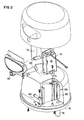
Figure 2 is an exploded perspective view of a representative upper housing of the multi component counter top water filtration of the present disclosure; -
Figure 3 is an exploded perspective view of a representative system monitor of the multi component counter top water filtration system of the present disclosure -
Figure 4 is a perspective view of a representative circuit board utilized in the representative system monitor ofFigure 3 ; -
Figure 5 is a perspective view of a representative system monitor ofFigure 3 ; -
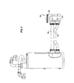
Figure 6 is a perspective view of the a representative section of the lower housing of the multi component counter top water filtration system of the present disclosure; -
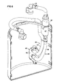
Figure 7 is a perspective view of the representative section of the lower housing ofFigure 6 viewed from a different perspective including a representative diverter valve and associated tubing; -
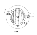
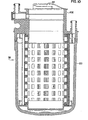
Figure 8 is a top view of a representative pressure vessel of the multi component counter top water filtration system of the present disclosure; -
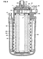
Figure 9 is a cross sectional view taken all along line 9-9 ofFigure 8 of the representative pressure vessel of the multi component counter top water filtration system ofFigure 8 ; -
Figure 10 is a partial cross sectional view similar to that ofFigure 9 but including the center core divider separating the filter media cartridges of the pressure vessel; -
Figure 11 is a perspective view of the upper portion of the pressure vessel ofFigures 8-10 ; -
Figure 12 is the top few of the upper portion of the pressure vessel ofFigure 11 ; -
Figure 13 is a cross-section of a representative pressure relief valve take along line 13-13 ofFigure 12 ; -
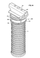
Figure 14 is a perspective view of a representative inner filter cartridge assembly of the pressure vessel of the multi component counter top water filtration system of the present disclosure; -
Figure 15 is a perspective view of a representative new and innovative end cap for interaction with the inner filter cartridge for sealing the pressure vessel and for providing a path for filtered water out of the pressure vessel; -
Figure 16 is a top few of the representative end cap ofFigure 15 ; -
Figure 17 is a cross sectional view of the end cap ofFigure 15 and 16 taken along lines 17-17 ofFigure 16 ; -
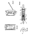
Figure 18 is a top view of a representative flow control device/magnet of the multi component counter top water filtration system of the present disclosure; -
Figure 19 is a cross sectional view of the flow control/magnet ofFigure 18 taken along line 19-19; -
Figure 20 is a planned view of the representative battery box for use with the multi component counter top water filtration system of the present disclosure; -
Figure 21 is a perspective view of the battery box theFigure 20 ; -
Figure 22 is a partial perspective view of the battery compartment and the circuit board housing positioned inside the representative upper housing of the multi component counter top water filtration system of the present disclosure; -
Figure 23 is a representation of the various stages displayed by the representative system monitor of the multi component counter top water filtration system of the present disclosure; -
Figures 24A and 24B illustrate the insertion of the carbon filter cartridge into the pleated membrane filtration media cartridge of the multi component counter top water filtration system of the present disclosure; -
Figures 25 A-C illustrates the assembly of the representative pressure vessel into the lower housing of the multi component counter top water filtration system of the present disclosure; -
Figures 26 A and 26 B illustrate connection of the hose snap on assemblies to the inlet of the representative pressure vessel of the multi component counter top water filtration system of the present disclosure; -
Figure 27 illustrates the connection of the outlet of the representative pressure vessel of the multi component counter top water filtration system of the present disclosure; -
Figure 28 illustrates a representative operable connection between the water source and a representative diverter valve of the multi component counter top water filtration system of the present disclosure; -
Figures 29 A and 29 B illustrates the installation of the representative upper housing to the representative lower housing of the multi component counter top water filtration system of the present disclosure; -
Figure 30 illustrates a representative first setting of the diverter valve of the multi component counter top water filtration system of the present disclosure used for obtaining unfiltered spray hot and cold water; -
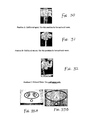
Figure 31 illustrates a representative a second setting of the diverter valve of the multi component counter top water filtration system of the present disclosure used for obtaining unfiltered stream hot and cold water; -
Figure 32 illustrates a representative a third setting of the diverter valve of the multi component counter top water filtration system of the present disclosure used for obtaining filtered and cold water only; -
Figures 33 A and B illustrate the interactive display of the system monitor in the activated condition which indicates that water is running thru the system or the test button has been pushed and indicates the capacity remaining in each of the filters of the multi component counter top water filtration system of the present disclosure; -
Figure 34 illustrates the battery life indicator blinking indicating that there is approximately two weeks of battery life remaining in the representative system monitor of the multi component counter top water filtration system of the present disclosure; -
Figures 35 A and B illustrate the method for resetting the representative monitor to the start position by pressing the test button below the monitor and the reset button under the upper housing simultaneously such that all lights are illuminated of the multi component counter top water filtration system of the present disclosure; -
Figures 36 A and B illustrate the display of viewable on the representative monitor that indicates that the inner carbon filter requires replacement; -
Figures 37 and 38 illustrate the procedure for removing carbon block filter cartridge from the pressure vessel of the multi component counter top water filtration system of the present disclosure; -
Figures 39 A and B illustrates the procedure for reinserting the carbon block filter cartridge back into the pressure vessel of the multi component counter top water filtration system of the present disclosure; -
Figures 40 A and B illustrate the display viewable on the interactive monitor after the reinsertion of the court to block filter cartridge into the pressure vessel of the multi component counter top water filtration system of the present disclosure; -
Figure 41 illustrates the procedure for utilizing the pressure relief valve to remove any air that may be trapped in the pressure vessel in the vicinity of the pleated membrane filtration media cartridge of the multi component counter top water filtration system of the present disclosure; -
Figures 42 A and B illustrate the display viewable on the system monitor that indicates that the countdown for replacement of the pleated membrane filtration media cartridge has begun for the multi component counter top water filtration system of the present disclosure; -
Figure 43 illustrates the display viewable on the system monitored that indicates that both the carbon filter and the pleated membrane filtration media cartridges require replacement in the multi component counter top water filtration system of the present disclosure; -
Figures 44 A-F illustrates a representative procedure for replacing the replacement pressure vessel consisting of both the pleated membrane filtration media cartridge and the carbon block filtration media cartridges in the lower housing after removal thereof; -
Figures 45 A in the illustrate the procedure for resetting the interactive display to ensure the correct countdown for the next sequence for the multi component counter top water filtration system of the present disclosure; and -
Figure 46 illustrates the flushing of the replacement carbon block filtration media cartridge and the replacement pleated membrane filtration media cartridge in order to remove any carbon residue and trapped air bubbles in the system with the diverter valve being set to the filtered water position of the multi component counter top water filtration system of the present disclosure. - The present disclosure relates to a multi component counter top water filtration system having several new and unique features, including but not limited to, a counter top
water filtration system 50 having two filtration media, one media being replaceable at least twice before the second media exceeds its useful life and requires replacement, presently preferably, both filtration media being housed in a single pressure vessel and, including but not limited to, a counter top water filtration system wherein the plumbing and electronic components are separated such that the lower housing component houses the plumbing components, including but not limited to, the water filtration pressure vessel, tubing and flow indication signaling device and the upper housing component houses the electronics components, including but not limited to,th e monitor 180, batteries and the flow indication receiving device and filtration methods related thereto. - As illustrated in
Figure 1 , thesystem 50 of the present disclosure includes four major components, those being anupper housing 52, for housing the electrical components, alower housing 54, for housing apressure vessel 56, thepressure vessel 56 being operatively positioned in thelower housing 54 and comprising at least two different filter media cartridges and plumbing components for connecting thepressure vessel 56 to the end users water supply. Each of these major components will now be described in detail. - As illustrated in
Figures 1-2 , theupper housing component 52 comprises anopen area 60 for encasing theupper portion 62 of thepressure vessel 56 and for operatively cooperating with thelower housing component 54. As illustrated, the electronic components 66 of thesystem 50 are operatively positioned therein including the circuit board and other conventional components. As illustrated inFigures 3-5 , thecircuit board 70 andbattery compartment 72 for housing the batteries that power the electrical system are operatively positioned internal of theupper housing 52. Adjacent to thebattery compartment 72 is aprotrusion 74 that extends from and beyond thelower surface 76 of theupper housing component 52 which is adapted for mating with a correspondingfirst aperture 77 operatively formed in thelower housing component 54. Areed switch 80 is operatively positioned inprotrusion 74 of theupper housing component 52 with amagnet 82 being operatively positioned in thelower housing 54 for cooperation therewith. - The
lower housing component 54 comprises a generallyhollow container 84 presently preferably made of plastic, and includingstructure 86 for accommodatingplumbing 88 such as, forexample tubing 89, for interfacing with thepressure vessel 56 that contains the filter cartridges. As illustrated inFigure 6 , thelower housing component 54 includes asec ond aperture 90 formed in the side thereof for routing theplumbing tubing 89 into the interior 92 of thelower housing component 54. -
Inlet 94 andoutlet 96 tubing, for operatively connecting the end users water supply (not shown) to thepressure vessel 56, is illustrated inFigures 1 and7 .Structure 99 for operatively connecting to the end users water supply is operatively positioned at one end of both theinlet 94 and theoutlet 96 tubing. Thestructure 99 includes a conventional selectableposition diverter valve 98 for selectively routing water from the water supply to thepressure vessel 56 and back to the selectable positioneddiverter valve 98. - As illustrated in
Figures 1 and8-13 , thepressure vessel 56 of the present disclosure comprises a lower pressure element 100, presently preferably made of injected molded plastic, and anupper pressure element 102, also presently preferably, made of injected molded plastic. The lower and the upper injected moldedpressure elements - The
lower pressure element 100 comprises an outer hollow area 104 for encasing a first filter media cartridge (membrane) 106 and a secondhollow area 108 interior of the outer hollow area 104 for removably receiving a second filter media cartridge 110 (carbon block). As illustrated, theopen end 112 of theupper pressure element 102 of thepressure vessel 56 comprisesstructure 114 for operatively removably positioning the secondfilter media cartridge 110 interior of the firstfilter media cartridge 106. - The
inlet 94 plumbing tubing is operatively connected to thepressure vessel 56 via aninlet port 116 operatively positioned in theupper pressure element 102 of thepressure vessel 56. As illustrated inFigures 1 ,8-13 , aconventional connector 118 is operatively connected to aninlet port 116 such that the water is routed into aspace 120 formed between theinner wall 122 of thelower pressure element 100 of thepressure vessel 56 and the first filter media. As illustrated, anoutlet port 128 for transferring filtered water from thepressure vessel 56 back to the selectableposition diverter valve 98 is operatively positioned so that the filtered water exits thepressure vessel 56 via theupper end 130 of acenter core assembly 132 operatively removably positioned in theupper pressure element 102, as will be explained in more detail below, and then through theoutlet 96 plumbing tubing operatively connected to theoutlet port 128 in theneck 131 of theupper pressure element 102 of thepressure vessel 56. Additionally, apressure relief value 133 is operatively positioned on theupper surface 134 of theupper pressure element 102 of thepressure vessel 56 for allowing any air that may become trapped on the backside of the first orouter filter cartridge 106 to be bleed out of the system so that water can efficiently flow through theouter filter cartridge 106. As is known to those skilled in the art, when air becomes trapped, there is not sufficient pressure to overcome the bubble point and allow the water to displace the air through the filter medium so that the water can flow through the filter medium. - Now that we have described the overall system generally, a more detailed description of the
overall system 50 and each sub component follow. - One unique feature of the present disclosure relates to the filtration cartridge construction and the filtration media performance balancing scheme. As is known, cartridges typically house a singular media type such as, for example, sediment, carbon block or membrane. Known prior combination filters that house several media types, such as, for example, a split prefilter have typically consisted of a carbon media and a sediment filter in a singular component housing. In these type combination filters, when a combination filter cartridge was replaced, all media types were changed at the same time. Each filter cartridge was considered depleted based on the filtration media that was exhausted first. As would be understood by those skilled in the art, there was usually still some useful life remaining in one of the media that was disposed of when the cartridge was changed.
- In order to maximize filter performance in known combination filters, the different filtration media utilized therein must be balanced to insure that the end user does not dispose of the filtration media having an unacceptable amount of useful filtration life remaining or excessive having filtration life that has not yet been exhausted. Some filtration media have a much greater potential useful life than other filtration media. As mention above, the useful filtration life disparity between various filtration media causes a balance problem when the size of one or more of the filtration media is a limiting factor. For example, if the useful filtration life disparity between to filter media is 6x, than the choice becomes whether to increase the size of the lower useful life filtration media by 6 times, thereby resulting in a significantly larger housing or, to decrease the size of the greater useful life filtration media by 1/6th. As is known in the art, there are numerous situations where either alternative is either impossible or unacceptable.
- The present disclosure provides an acceptable solution to the filtration media balancing problem by allowing the end user to change the filtration media that has the shortest useful life at a different rate than the filtration media having the greater useful life. One specific representative example includes, but is not limited to, a
pressure vessel 56 co mprising a carbon blockfiltration media cartridge 110 and a pleated membranefiltration media cartridge 106. Depending on the filtration media performance, the carbonblock filtration media 110 cartridge could exceed its useful life in about 4 months, while the pleated membrane filtration media cartridge might not exceed its useful life for as long as 2 years, a 6x disparity. If both filtration media were in a typicalsingle pressure vessel 56, disposing of thesingle pressure vessel 56 containing the two different filtration media at about the 4 month point would result in the loss of about 20 months of useful membrane life. - In an effort to address this problem, the
pressure vessel 56 of the present disclosure includes a removablecenter core assembly 132 including the carbon blockfiltration media cartridge 110 that would provide for the changing of the carbon blockfiltration media cartridge 110 mentioned above at about the 4 month point and leaves the pleated membrane filtration media cartridge in place in thepressure vessel 56. At this point, a new removablecenter core assembly 132 including the carbon blockfiltration media cartridge 110 would be operatively inserted into thepressure vessel 56 while the membrane filtration media cartridge still has useful life. In this representative example, the carbon blockfiltration media cartridge 110 component would be changed about 6 times more often than the membrane filtration media cartridge component. An additional feature of the preferredcenter core assembly 132 including the carbon blockfiltration media cartridge 110 is that, as presently constructed, the end user does not have to disconnect anyplumbing 88 or electronic components 66 in order to change out the carbon block componentfiltration media cartridge 110 component, as will be discussed in more detail below. - As should be readily apparent, the
representative pressure vessel 56 structure described above provides a major benefit to the end user in that the end user is only changing the filtration media cartridge that has exhausted its useful life and not the filtration media cartridge that still has useful life. - As illustrated in
Figures 14-17 , another representative and unique feature of the present disclosure is the structural design of thecenter core assembly 132end cap 140 which includes anupper plate 142 and alower plate 144, thelower plate 144 includes aflow path 146 for the fluid communication outside of thepressure vessel 56 without the need for a separate fluid port being position in theend cap 140. - One especially useful benefit of this particular design is that the changing of the
center core assembly 132 filtration media cartridge is accomplished without disconnecting any of the multi component counter top water filtration systems plumbing 88 fittings. As should be apparent, when an end user changes thecenter core assembly 132 filtration media cartridge at a frequency greater than theouter pressure vessel 56 filtration media cartridge, a previously unattained convenience ofbeing able to change thatcenter core assembly 132 filter, simply and without disconnecting any plumbing connections is highly desirable and is achieved by the multi component counter topwater filtration system 50 of the present disclosure. - In the prior Cuno
U.S. patent No. 6,325,929 to Bassett , an end cap is attached to the filter media and is part of the pressure boundary. This end cap has no fluid port because its sole function is to close thepressure vessel 56. Thus, fluid communication outside thepressure vessel 56 is achieved through the opposite end or other locations of thepressure vessel 56. - In the case of the new counter top
water filtration system 50 of the present disclosure, thecenter core assembly 132 filter or filtration media cartridge is replaced through the top or fluid connection end of thepressure vessel 56. As it would be rather inconvenient to disconnect any of theplumbing 88 fittings when the end user needed to replace thecenter core assembly 132 filter or filtration media cartridge, the new andinnovative end cap 140 of the present disclosure fluidly communicates outside thepressure vessel 56 via aport 128 operatively positioned on theneck 131 of thepressure vessel 56 which is then operatively connected to theoutlet 96 fitting and tubing. - Because the outlet of a filter media cartridge is typically in the center, and in this case, the outlet is on the
neck 131 or side of thepressure vessel 56, a new and innovativecenter core assembly 132 lowerend cap plate 144 was developed to specifically address this situation. As shown inFigure 14-17 , thelower plate 144 of thecenter core assembly 132upper end cap 140 is operatively connected to the filter media cartridge and serves as the media cartridge end cap. Thelower plate 144 is sealed to the inside of theneck 131 by an O-Ring seal. In addition, the lower plate includes at least oneaperture 146 operatively positioned, presently preferably, in the center thereof in order to allow the filtered water to pass through thelower plate 144 and out of the multi component counter topwater filtration system 50 of the present disclosure via theoutlet 128 operatively positioned in fluid communication therewith. - As shown in
Figures 1 and14-17 , theupper plate 142 of thecenter core assembly 132upper end cap 140 is located parallel to and above thelower plate 144. As shown, theupper plate 142 is also sealed to the inside of theneck 131 by an O-Ring seal. Theupper plate 142 is solid with no fluid passageways therein and thus, becomes the closure element of thepressure vessel 56. The two plates, upper 142 and lower 144, are held together bysupport ribs 148 such that a substantially rigid component results. - As illustrated, the
outlet port 128 and theplumbing 88 fitting related thereto is operatively positioned between the upper 142 and lower 144 plates on theneck 131 of thepressure vessel 56. The filtered fluid from thecenter core assembly 132 filtration media cartridge passes through the fluid passage means or at least oneaperture 146 formed in thelower plate 144 into anarea 150 formed between the upper 142 and lower 144 plates. From thearea 150 between the two plates, the filtered fluid is allowed to pass though theoutlet port 128 to theoutlet plumbing 88 operatively positioned between the outlet port and the end userselectable valve 98 at the point of use. - This new and innovative
center core assembly 132upper end cap 140 configuration of the present disclosure that includes the upper and lower plates as described above, facilitates the removal and replacement of thecenter core assembly 132 filtration media cartridge by an end user without having to disconnect the fluid outlet fitting. Another benefit of the new andinnovative end cap 140 configuration of the present disclosure is the reliability improvement and cost reduction resulting from the reduction in the number of parts that constitute thecenter core assembly 132upper end cap 140. Having anend cap 140 whose function is to insure that fluid passes through the filter media, to also be thepressure vessel 56 closure, and be the method of communicating with the outlet plumbing 88 saves both part count and labor versus assembling various possible different configurations. - Another new, unique and innovative feature of the present disclosure comprises a
handle 160 configuration that is configured such that the O-Ring seals are disengaged without rotation in order to reduce the breakout force required to remove and replace thecenter core assembly 132 filter media cartridge. - In order to meet certain filter performance specifications related to the amount of contaminants removed, one representative embodiment of the
center core assembly 132 filtration media cartridge required an about 5.7cm (2.25 inch) outside diameter. Such a sized outside diameter means that theopening 112 in the top of thepressure vessel 56 need ed to be some what larger in diameter. It is known that as the diameter of an O-Ring sealing area increases so does the force required to dislodge the O-Ring seal from their closed operating position. As is also known, the longer the O-Ring seal remains in the closed operative position, the force required to break the seal out from the closed operating position increases. Thus, there is a finite limit to the sealing diameter where it is no longer possible to overcome the breakout force by hand and additional force, such as, for example, a wrench is required in order to provide sufficient force to break the O-Ring seal. - In order to reduce the torque required to be transmitted to the
center core assembly 132 filtration media cartridge to overcome the breakout force in order to remove thecenter core assembly 132 filtration media cartridge, a swivelinghandle 160 configuration was developed. In the case where the filtration media cartridge is removed from fluid connection by a quarter turn method, the O-Ring seal is rotationally turned as it is translated out of the O-Ring sealing area. As the filtration media cartridge is removed from the operating position, there are at least two force components to overcome, the rotationally turning force or rotation component (most difficult to overcome) and the translating force component (less difficult to overcome). Further, each of these components has breakout forces that must also be overcome. Together these two force components have traditionally proven to be very difficult to overcome especially if the sealing area/diameter is large, and the O-Ring has been operatively engaged in the operating position for a long time. By assembling the sealingend cap 140 and the removinghandle 160 as two components and operatively connecting them with a swiveling joint 162, the two force componen ts required to remove thecenter core assembly 132 filtr ation media cartridge is effectively reduced to the translation force component and its breakout force component only. Additionally, the swivel joint 162 provides a mechanical advantage. - In this case, the rotational force component is effectively significantly reduced from a theoretical value of 250 to a working value of about 2.3cm (20 in* lbs) by use of the
swivel joint 162. By providing for thehandle 160 to swivel with respect to theend cap 140, thehandle 160 swivels to engage the filter media cartridge removal ramps 137 while theend cap 140 remains in place in the operating position, as thehandle 160 continues to rotate and starts to translate due to the removal ramps 137. Since thehandle 160 is attached to theend cap 140 and thus theend cap 140 follows thehandle 160 in the translation. Since the ramp profile is not angular but is instead has a cam profile where the beginning of the cam is very shallow in order to apply the greatest mechanical advantage such that the breakout force is overcome. Since the required force is reduced as soon as the O-Ring begins to move, the cam ramps become steeper toward the end thereof. The converse is also true, as when the end user inserts a newcenter core assembly 132 filter into the operating position, theend cap 140 does not rotate during installation, reducing the effort required to accomplish installation. - Another new and innovative feature of the present counter top
water filtration system 50 is the effective separation of the electronic components 66 and theplumbing 88. - It has been observed during the development and deployment of other prior counter top water filtration devices that housing the electronic components 66 in the same location as the
pressure vessel 56 can cause condensation to accumulate on the printed circuit board 70 (PCB) and short out the electrical components 66. For this and other reasons, the counter topwater filtration system 50 of the present disclosure houses the electronic components 66 in theupper housing 52 and theplumbing 88 components in thelower housing 54. In this way, the electronic components 66 are isolated from possible condensation and other environmental factors that might cause the electronic components 66 to malfunction, such as, for example, short out. In order to accomplish this goal, the flow sensing sendingcomponent 67 and the flow sensing receivingcomponent 69 housed inprotrusion 74, have been designed to be housed in separate housings components of thesystem 50. - Typically when designing a prior counter top system, the flow switch had been a singular component. As is known, two components comprise a typical conventional singular component flow switch. One component comprises a flow sensing sending
component 67 and amagnet 82 that typically resides in aflow chamber 81. When flow occurs, themagnet 82 displaces in the direction of the flow. This displacement puts the magnet's magnetic field in proximity to a flow sensing receivingcomponent 67 andreed switch 80. Thereed switch 80 senses the magnetic field and closes to complete an electronic circuit. Because the typical magnets used in flow switches are relatively weak, thereed switch 80 needs to be located in very close proximity to themagnet 82. The need to be so proximity located is the primary reason flow switches have conventionally been sold as a singular component. - The counter top
water filtration system 50 of the present disclosure operatively positions themagnet 82 in aflow chamber 81 operatively connected to thelower housing 54 with thereed switch 80 being operatively connected to theupper housing 52. However, such location of the two components presented several problems that needed to be overcome in order to provide a robust counter topwater filtration system 50. The first problem encountered during the development of the counter topwater filtration system 50 of the present disclosure was that initially it was determined that themagnet 82 and thereed switch 80 need ed to separated by about 3 times the normal distance. This increased separation distance required a relativelystronger magnet 82 and the development of a new method for insuring that when the two components of the flow switch effectively operatively interact together, the two components are always positioned safely within the flow switch activation zone. - Without the above described
flow switch 80 configuration, when the end user needed to replace thecore assembly 132 fluid filtering media cartridge, the end user would be required to either disconnect theplumbing 88 or disconnect the electronic connectors. In the presently preferred embodiment of the present disclosure, the end user simply disassembles theupper housing 52 from thelower housing 54 without disconnecting either theplumbing 88 or the electronic connections. Removing theupper housing 52 exposes theplumbing 88 and fluid filtering media cartridges orpressure vessel 56 housed in thelower housing 54. This new and innovative configuration is a great convenience to the end user, as they do not need to remember to disconnect something or have to remember to reconnect something. Thus, the above described configuration that requires the separation of the two flow switch components is believed new and unique with respect to prior flow switch technology. - Now that we have described the various components of the multi component counter top
water filtration system 50 of the present disclosure, we will describe how an end user would place thesystem 50 in operation in the environment of use. First, the end user would separate theupper housing 52 from thelower housing 54 of the multi component counter topwater filtration system 50, turn theupper housing 52 over and locate the battery compartment 72 (seeFigures 2 and20-21 ) inside the multi component counter topwater filtration system 50upper housing 52 and remove thebattery compartment cover 73. Install 2 AA batteries in thebattery compartment 72 insuring that the orientation of the (+) and (-) terminals for each battery is correctly installed. - Replace the
cover 73 of thebattery compartment 72 once the batteries are installed. To test the battery connections and to ensure that the system monitor 180 is functioning, push thebutton 182 on the front of theupper housing 52 and hold it in for about 6 seconds. The system monitor 180 should cycle through its functions with all lights activated in sequence. If the system monitor 180 does not work, the the batteries should be checked (seeFigures 20 and22 ; note that sequence represented byFigure 23 will occur each time before the next bar will disappear from the filter symbol 2 display.) - Remove the pleated membrane filtration media cartridge, (the larger of the two cartridges) from the box. Remove the
carbon filter cartridge 110 from the box and insert the carbon filter cartridge into the center portion of the pleated membranefiltration media cartridge 106. As best illustrated inFigure 23 A and B , insert the carbon filter cartridge all the way down into the pleated membrane filtration media cartridge and rotate the carbon block filtration media cartridge handle 160 all the way to the right until rotations stops. - As best illustrated in
Figure 24 A-C , first, insure that the hoses in thelower housing 54 are clear; second, align the two vertical ribs on the lower housing 54 t with the cut out in the opening of thelower housing 54 in order to allow thepressure vessel 56 to fit completely into thelower housing 54 of the multi component counter topwater filtration system 50; and then insert the assembled two filter assembly, which constitutes thesystem pressure vessel 56, into thelower housing 54 of the multi component counter topwater filtration system 50.. - Next, as best illustrated in
Figures 25 A and B , and30 , take the longer of the two hoses and guide it around the side of the assembledpressure vessel 56 and snap the end connector over theinlet 116 fitting on the other side of the assembledpressure vessel 56. Then, push the hose into the circular cut-out in the base of the remaining fitting. Snap the shorter hose onto the remainingoutlet 128 fitting. - Do not re-install the
upper housing 52 at this time. Theupper housing 52 will be installed after the multi component counter topwater filtration system 50 has been completely connected to the water supply structure, such as, for example, the faucet. - As best illustrated in
Figure 28 , connection to the water supply structure is accomplished by use of adiverter valve 98 at the end of the hoses. Thediverter valve 98 is then connected to the faucet chosen to supply cold water to the multi component counter topwater filtration system 50. The configuration of the end of the faucet should be matched to the appropriate adaptor (not shown) provided with the multi component counter topwater filtration system 50. Install the correct adaptor and connect thediverter valve 98 securely to the end of the faucet. Then, test thediverter valve 98 connection for leaks. At this point caution should be exercised to ensure that hot water is never used in the multi component counter topwater filtration system 50, as hot water will reduce the carbon filter's efficiency, among other potential adverse results thereof - Very slowly turn the cold water faucet on. Look for any water leaks at the
diverter valve 98 and in thelower housing 54 of the multi component counter topwater filtration system 50 where the hoses snap onto the fittings. If thediverter valve 98 orlower housing 54 fittings are leaking, reassemble the connections. If no leaks are observed, as best illustrated inFigures 29 A and B , install theupper housing 52 onto thelower housing 54 of the multi component counter topwater filtration system 50 making sure that theupper housing 52 snaps into place. - Before using the multi component counter top
water filtration system 50 for the first time and after every carbon filter replacement, the user must flush water through thecarbon filter cartridge 110 in order to remove any carbon residue and trapped air bubbles. While conducting the flush, be sure that thediverter valve 98 is set to the filtered water position. - The
diverter valve 98 has three settings that control the flow of water from the water source that a user may require. A user can access each setting by turning the control handle 101 on the right side of thediverter valve 98 to any one of three positions. As best illustrated inFigures 30-32 , Position A is for unfiltered spray, which is used for hot and cold water. Position B is for unfiltered stream, which is also used for hot and cold water. Position C is for filtered cold water only. Once thediverter valve 98 is confirmed to be in the correct position, position C, turn on and flush the system for at least 5 minutes. - In the event that the
diverter valve 98 is set for filtered flow and the diverted flow appears to be slower than expected or there is no water flowing from the filtered water outlet, air may be trapped in the pleated membrane filtration media cartridge filter housing. To resolve this situation, insure that the incoming cold water flow is on and that thediverter valve 98 is set to the filtered water position. Locate the red coloredpressure relief valve 131 button on the side to thepressure vessel 56 and push the button until water just begins to flow from thediverter valve 98 when set to the filtered water position. When water just begins to flow from thediverter valve 98, it indicates that the trapped air has been evacuated form thepressure vessel 56 and that thepressure vessel 56 is full of water. Filtered water should now flow normally from thediverter valve 98 when in the filtered water position. - As best illustrated in
Figure 33 A and B , the multi component counter topwater filtration system 50 includes an advanced system monitor 180. To test the monitor function, a user would press and hold thebutton 182 under themonitor 180 for about 6 seconds. Themonitor 180 should cycle through all its light functions and emit a "beep" at the end of the cycle to indicate that thesystem 50 is functioning properly. - The interactive display on the face of the multi component counter top
water filtration system 50 keeps a record of the remaining life in both the inner carbon filter cartridge (filter symbol 1), the outer pleated membrane filtration media cartridge (filter symbol 2) and the batteries, (2 AA). The display is only activated whenever water is running through thepressure vessel 56 of thesystem 50 or when the test button 182 (round button below the display) is pushed. When both of the filters are new, all lights for the filter symbol 1 and the filter symbol 2 will be illuminated on both sides as shown inFigure 33B . Illuminated green lights indicate the amount of filtration capacity remaining in each of the respective filters. - As filter capacity is diminished, the display for the inner carbon filter cartridge will change over a period of approximately 4 months or after the use of about 500 liters of water. The five green lights around the filter symbol 1 display will go out in sequence until only the symbol for the filter symbol 1 remains and flashes red, as best illustrated in
Figure 36 A . This red flashing display indicates that the inner carbon filter, the filter symbol 1, requires replacement. After each replacement of the inner carbon filter cartridge, one green light of the outer pleated membrane filtration media cartridge display will no longer illuminate during use with the exception of the first replacement. When the sixth carbon filter, inner carbon filter cartridge, has exhausted its useful life, all the green lights around the filter symbol 2 display will no longer illuminate during use and the filter symbol 2 will flash red, as best illustrated inFigure 36 B . At that time, the outer pleated membrane filtration media cartridge will require replacement along with the inner carbon filter cartridge , as represented in the following tables and in the Figures described above.Table 1 Liters consumed Filter Symbol 1 - Number of Green Lights Displayed 0 5 100 4 200 3 300 2 400 1 500 0 (Filter 1 Icon blinks Red indicating that it is time to change filter) Table 2 Liters Consumed Filter Symbol 2 - Number of Green Lights Displayed 0 5 500 5 1000 4 1500 3 2000 2 2500 1 3000 0 (Filter 2 Icon blinks Red indicating that it is time to change filter) - The battery life indicator appears at the bottom center of the oval faceplate of the
monitor 180. The indicator will not light under normal use except during amonitor 180 test cycle. The battery indicator will emit one red flash during the test cycle. As battery power is depleted and replacement is required, the indicator will blink red when the multi component counter topwater filtration system 50 is dispensing water. The blinking red battery light indicates that the user has approximately 2 weeks to replace the batteries. - If necessary, the
monitor 180 can be reset to the start position. Any history of water consumed and/or previous cartridge changes will be erased. To completely reset themonitor 180 to the start position, press both thetest button 182 below themonitor 180 and thereset button 184 under the cover at the same time and hold for about 2 seconds until you hear a "beep". Themonitor 180 circuitry will reset to 0 liters consumed and all green lights will be displayed. - We will next discuss the procedure used to change the filters beginning with the interior or the first carbon black filter cartridge, as best illustrated in
Figures 39 A and B . When the filter symbol 1 is flashing red, it indicates that the inner carbon filter cartridge requires replacement, as shown inFigure 36-B . - The inner carbon filter cartridge, when removed from the multi component counter top
water filtration system 50, will be wet. To avoid the possibility of any water dripping onto the countertop, the multi component counter topwater filtration system 50 should be placed in an empty sink or next to a sink. However, care should be taken to ensure that theupper housing 52 is not accidentally dropped. Further care should be taken to ensure that theupper housing 52 is never immersed in water or any liquid. - The inner carbon block
filtration media cartridge 110 is located in the center thepressure vessel 56 and is identified by its swivel handle 160 which has a hole in the center. At this point, it should be noted that there is no need to touch the wet portion of the filter. - As best illustrated in
Figure 39 A and B , hold thepressure vessel 56 with one hand and turn thehandle 160 of the cartridge counter-clock-wise. Lift the inner carbon block filtration media cartridge up and out of thepressure vessel 56. Be sure to empty any water remaining insidepressure vessel 56 andlower housing 54 by carefully inverting same over a sink before inserting a new inner carbon filter cartridge, in order to avoid possible overflow onto the counter during new filter cartridge installation. - Discard the used filter cartridge. Remove any protective sanitary wrapping from the new cartridge. Hold onto the
handle 160 to avoid touching the filter cartridge itself. In reverse order of cartridge removal, insert the new cartridge into thepressure vessel 56 and push down and turn thehandle 160 clockwise until thehandle 160 stop is felt. At this point, the replacement cartridge is now installed. - Before replacing the
upper housing 52 , the interactive display must be reset to ensure the correct countdown for the next carbon filter cartridge change. Thereset button 184 is located on the bottom of theupper housing 52. As best illustrated inFigure 40 A and B , to reset the interactive display, push and hold thebutton 184 in until a "beep" is heard (approximately 3 seconds). At this time, the interactive display will be reset to begin the countdown for the filter symbol 1, the carbon filter cartridge, to be replaced for the second time. Subsequent replacements of the filter symbol 1 will be carried out in the same manner as the initial replacement. - After replacing the
upper housing 52 and before resuming use of the multi component counter topwater filtration system 50, flush water must be run through the replaced carbon block filtration media cartridge in order to remove any carbon residue and trapped air bubbles. During this process, thediverter valve 98 must be set to the filtered water position. Next, the multi component counter topwater filtration system 50 is turned on and the system is flushed for at least 2 minutes. - As during initial installation, in the event that the
diverter valve 98 is set for filtered flow and the divert flow appears to be slower than expected or there is no water flowing from the diverter, air may be trapped in the pleated membrane filtration media cartridge filter housing. As before, to resolve this problem, insure that the incoming cold water flow is on and that the diverter flow is set to filtered water. As best illustrated inFigure 41 , locate the red coloredpressure relief valve 131 button on the side to thepressure vessel 56 and push the button until water just begins to flow from thediverter valve 98. When this occurs, it indicates that the trapped air has been evacuated form thepressure vessel 56 and that thepressure vessel 56 is full of water. Filtered water should now flow normally from thediverter valve 98. - At the end of this process, the re-set display now shows only 4 lights remaining around the filter symbol 2. This indicates that the countdown for the replacement of the outer pleated membrane filtration media cartridge has begun. When the sixth inner carbon filter cartridge has expired, all the lights around the filter symbol 2 will no longer illuminate during use and the filter symbol 2 will flash red. At that time, the outer pleated membrane filtration media cartridge will require replacement along with the inner carbon filter cartridge.
- When the sixth inner carbon filter cartridge has expired, the
interactive monitor 180 will alert the user that the outer pleated membrane filtration media cartridge also requires replacement. This should occur after approximately 2 years or after the consumption of about 3,000 liters of water. At that time, themonitor 180 will display both the filter symbol 1 and the filter symbol 2 symbols in red as shown inFigure 43 . - Outer pleated membrane filtration media cartridge replacement is somewhat similar to the inner carbon block filtration media cartridge replacement procedure. As mentioned above, in order to avoid the possibility of any water dripping onto your countertop, it is suggested that the end user place the multi component counter top
water filtration system 50 in an empty sink or next to a sink. As with the initial filter replacement, remove theupper housing 52 from thelower housing 54 and set theupper housing 52 aside. - The end user will now be changing the inner carbon block filtration media cartridge at the same time the outer pleated membrane filtration media cartridge is being changed. The end user will remove both cartridges together as an assembly, the
pressure vessel 56, from thelower housing 54. The carbon block filtration media cartridge is the filter that fits into the center of the pleated membrane filtration media cartridge housing portion of thepressure vessel 56. Thelower housing 54 includes two hoses operatively attached thereto. These two hoses are disconnected by pressing the grey button on each coupling and lifting the couplings from the fittings. During this operation, care should be taken to also remove the longer tube from its push-in fitting under the base of the other coupling. At this point, make sure that both hoses are pushed aside and lift the complete pleated membrane filtration media cartridge/carbon block filtration media assembly/pressure vessel 56 out of thelower housing 54 of the multi component counter topwater filtration system 50. - At this point, the exhausted filters should be properly discarded. The next step is to unwrap and otherwise prepare both new filters for use. Once accomplished, insert the new carbon block filtration media cartridge into the new pleated membrane filtration media cartridge filter housing portion of the
pressure vessel 56, turn the carbon filter block filtration media cartridge handle 160 clockwise until one feels it stop, which completes the assembly of thenew pressure vessel 56. - Before replacing the new assembly/
pressure vessel 56, the two vertical ribs on the pleated membrane filtration media cartridge housing must align with the cut out in the opening of thelower housing 54 in order to allow the filter assembly/pressure vessel 56 to fit completely into thelower housing 54 of the multi component counter topwater filtration system 50, as best illustrated inFigures 44 A-C . During reassembly, these ribs should be lined up with the corresponding cut-out in thelower housing 54 of the multi component counter topwater filtration system 50 and place the cartridge assembly/pressure vessel 56 into thelower housing 54 and position the hose back into the cut-out in the base of the fitting. At this point, both hoses are re-connected to their corresponding fittings by pushing the tube end couplings all the way down onto the housing fittings until they "click" in place, as best illustrated inFigures 45 A-C . - Before replacing the
upper housing 52, the user must reset the interactive display to ensure the correct countdown for the next two year sequence via thereset button 184 located on the bottom of theupper housing 52, as best illustrated inFigures 46 A-B . In order to accomplish this, the user pushes and holds both the test and resetbutton 184 simultaneously until a "beep" is heard (approximately 3 seconds). At this point, the interactive display is reset to begin the countdown for both Filter 1 and Filter 2. Replace theupper housing 52 as before. - Before using the multi component counter top
water filtration system 50 for the first time, the user must flush water through the replaced carbon filter cartridge and the replaced pleated membrane filtration media cartridge in order to remove any carbon residue and trapped air bubbles. While conducting the flush, be sure that thediverter valve 98 is set to the filtered water position. Once thediverter valve 98 is confirmed to be in the correct position, turn on and flush the system for at least 5 minutes as best illustrated in Figure 47. - As during initial installation, in the event that the
diverter valve 98 is set for filtered flow and the divert flow appears to be slower than expected or there is no water flowing from thediverter valve 98, air may be trapped in the pleated membrane filtration media cartridge filter housing. As before, to resolve this problem, insure that the incoming cold water flow is on and that the diverter flow is set to filtered water. Locate the red coloredpressure relief valve 131 button on the side to thepressure vessel 56 and push the button until water just begins to flow from thediverter valve 98. When this occurs, it indicates that the trapped air has been evacuated form thepressure vessel 56 and that thepressure vessel 56 is full of water. Filtered water should now flow normally from thediverter valve 98. - Now that we have described the various components of the multi component counter top
water filtration system 50 of the present disclosure and how an end user would place thesystem 50 in operation in the environment of use, we will know describe the operation of the multi component counter topwater filtration system 50 of the present disclosure. - As best illustrated in
Figure 7 , thediverter valve 98 is operatively connected to water source, such as, for example, a faucet (not shown). When the end user wants to filter water, the diverter valve is placed in the filter water position and water flows from the diverter valve to the pressure vessel viatubing 94. As best illustrated inFigure 6 ,tubing 94 is routed inside oflower housing 54 and eventually toinlet 116, throughouter cartridge 106 andinner cartridge 110 intohollow area 150 and out throughoutlet 128, as illustrated inFigure 9 . - Returning again to
Figures 6 and7 , the filtered water exists thelower housing 54 viatubing 96 after passing through thecomponent 67housing magnet 82 and eventually exits' thediverter valve 98 via filteredwater exit 170. The flow sensing sendingcomponent 67 is conventional and comprises anupper housing 190, alower housing 192, themagnet 82, aspring 194, aspring retainer washer 196, aflow washer 198, aflow washer seat 200 and ametering piston 202. This flow sending sensing component operates in conjunction with the flow receiving sensing component in a conventional manner, as would be known to those skilled in the art. - The most recently developed embodiment of the present disclosure includes the relocation of the
flow washer 198, as shown inFigure 19 , to theposition 199, as now indicated inFigure 9 , as it has been determined that such relocation of theflow washer 198 results in a quieter operation of the multi component counter top water filtration system of the preset disclosure. - While the systems, articles, apparatus and methods for using and making the articles contained herein constitute preferred embodiments of the invention, it is to be understood that the invention is not limited to these precise articles, apparatus and methods, and that changes may be made therein without departing from the scope of the embodiments appended hereto.
Claims (11)
- An apparatus for reducing the breakout force required to remove an installed filter media cartridge (110) from a pressure vessel (56), the apparatus comprising:a sealing end cap (140) attached to the filter media cartridge for sealing the filter media cartridge into the pressure vessel;a handle (160) attached to and rotatable with respect to the sealing end cap;wherein the handle (160) is rotatable to engage a removal ramp (137) on the pressure vessel, the removal ramp comprising a cam profile having a shallow portion and a steeper portion for translating the filtration media cartridge from the pressure vessel such that rotation of the handle engages the removal ramp to cause translation, but not rotation, of the sealing end cap to remove the filter media cartridge from the pressure vessel, wherein the sealing end cap (140) comprises one or more O-Ring seals; andthe handle (160) is rotatable to initially engage the shallow portion of the cam profile to apply the greatest mechanical advantage such that the breakout force of the sealing end cap is overcome and the sealing end cap begins to translate.
- The apparatus of claim 1 wherein the handle (160) is further rotatable to engage the steeper portion of the cam profile to translate the sealing end cap (140) out of the pressure vessel.
- The apparatus of any claim 1 or claim 2 wherein the handle (160) is rotatable through a quarter turn to disengage the sealing end cap (140) from the pressure vessel.
- The apparatus of any of claims 1-3 wherein the pressure vessel (56) comprises at least two different replaceable filter media components (110, 106), wherein the filter media cartridge is removably inserted within an opening (112) within a center core (132) of a second filter media cartridge (106).
- The apparatus of claim 4 wherein the filter media cartridge (110) comprises a chemical reduction filter media and the second filter media cartridge (106) comprises a particulate reduction filter media.
- The apparatus of any of claims 4-5 wherein the filter media with the shortest life can be changed at a different rate than the filter media having the greater life.
- A method of removing a filter media cartridge (110) from a pressure vessel (56)comprising:providing a sealing end cap (140) attached to the filter media cartridge, the sealing end cap sealing the filter media cartridge into the pressure vessel;providing a handle (160) attached to and rotatable with respect to the sealing end cap;providing a removal ramp (137) on the pressure vessel, the removal ramp comprising a cam profile having a shallow portion and a steeper portion ;rotating the handle to engage the removal ramp such that rotation of the handle causes translation, but not rotation, of the sealing end cap to remove the filter media cartridge from the pressure vessel,wherein the sealing end cap (140) comprises one or more O-Ring seals, and the step of rotating the handle comprises the step of:rotating the handle (160) to initially engage the shallow portion of the cam profile to apply the greatest mechanical advantage such that the breakout force of the sealing end cap (140) is overcome and the sealing end cap begins to translate.
- The method of claim 7 comprising further rotating the handle (160) to engage the steeper portion of the cam profile to translate the sealing end cap (140) out of the pressure vessel.
- The method of any of claims 7-8 comprising rotating the handle (160) through a quarter turn to disengage the sealing end cap (140) from the pressure vessel.
- The method of any of claims 7-9 wherein removing the filter media cartridge (110) from the pressure vessel comprises removing the filter media cartridge from an opening (112) within a center core of a second filter media cartridge (106).
- The method of claim 10 comprising changing the filter media with the shortest life at a different rate than the filter media having the greater life.
Applications Claiming Priority (2)
| Application Number | Priority Date | Filing Date | Title |
|---|---|---|---|
| US61431604P | 2004-09-29 | 2004-09-29 | |
| EP05800186A EP1793908B1 (en) | 2004-09-29 | 2005-09-29 | Counter top water filtration system |
Related Parent Applications (1)
| Application Number | Title | Priority Date | Filing Date |
|---|---|---|---|
| EP05800186.8 Division | 2005-09-29 |
Publications (2)
| Publication Number | Publication Date |
|---|---|
| EP2241361A1 EP2241361A1 (en) | 2010-10-20 |
| EP2241361B1 true EP2241361B1 (en) | 2011-11-09 |
Family
ID=35510981
Family Applications (2)
| Application Number | Title | Priority Date | Filing Date |
|---|---|---|---|
| EP05800186A Not-in-force EP1793908B1 (en) | 2004-09-29 | 2005-09-29 | Counter top water filtration system |
| EP10161996A Not-in-force EP2241361B1 (en) | 2004-09-29 | 2005-09-29 | Counter Top Water Filtration System |
Family Applications Before (1)
| Application Number | Title | Priority Date | Filing Date |
|---|---|---|---|
| EP05800186A Not-in-force EP1793908B1 (en) | 2004-09-29 | 2005-09-29 | Counter top water filtration system |
Country Status (9)
| Country | Link |
|---|---|
| US (1) | US8216466B2 (en) |
| EP (2) | EP1793908B1 (en) |
| JP (1) | JP2008514427A (en) |
| CN (1) | CN100540108C (en) |
| AT (2) | ATE470493T1 (en) |
| AU (1) | AU2005291873B2 (en) |
| BR (1) | BRPI0516180A (en) |
| DE (1) | DE602005021799D1 (en) |
| WO (1) | WO2006039538A2 (en) |
Cited By (1)
| Publication number | Priority date | Publication date | Assignee | Title |
|---|---|---|---|---|
| WO2021127215A1 (en) * | 2019-12-17 | 2021-06-24 | Jonell filtration Products, Inc. | Confined space sealing system and method |
Families Citing this family (32)
| Publication number | Priority date | Publication date | Assignee | Title |
|---|---|---|---|---|
| US20070221561A1 (en) * | 2006-03-22 | 2007-09-27 | 3M Innovative Properties Company | Liquid filtration systems |
| KR20080083903A (en) * | 2007-03-13 | 2008-09-19 | 삼성전자주식회사 | Water purifying device |
| GB0715269D0 (en) | 2007-08-04 | 2007-09-12 | Parker Hannifin Ltd | Filter assembly |
| GB0715247D0 (en) * | 2007-08-04 | 2007-09-12 | Parker Hannifin Ltd | Filter assembly |
| US7935255B2 (en) * | 2007-09-06 | 2011-05-03 | Cummins Filtration Ip, Inc. | Filter cartridge |
| US7749383B2 (en) * | 2007-09-06 | 2010-07-06 | Cummins Filtration Ip, Inc. | Filter cartridge with crush ribs |
| EP2373394B1 (en) | 2008-11-04 | 2016-04-20 | 3M Innovative Properties Company | Fluid interconnect |
| EP2349526B1 (en) | 2008-11-04 | 2014-04-23 | 3M Innovative Properties Company | Filter element and seal therefor |
| TWI516451B (en) * | 2009-01-12 | 2016-01-11 | 通路實業集團國際公司 | Point-of-use water treatment system |
| US8308942B2 (en) * | 2010-05-14 | 2012-11-13 | Paragon Water Systems, Inc. | Filter system with removable enhancement media |
| US8261919B2 (en) | 2010-08-25 | 2012-09-11 | Dow Global Technologies Llc | Fluid filter module including handle |
| EP2680245B1 (en) * | 2011-02-25 | 2018-12-19 | Panasonic Corporation | Wireless device for automated meter reading |
| EP2719668A4 (en) * | 2011-06-10 | 2014-11-12 | Mitsubishi Rayon Co | Water purification cartridge and pitcher-type water purifier |
| EP3620221A1 (en) | 2013-01-21 | 2020-03-11 | A.O. Smith Water Treatment (North America), Inc. | Method of assembling a liquid filtration system |
| US9994459B2 (en) | 2013-03-15 | 2018-06-12 | Zero Technoligies, Llc | Gravity-fed and dual ion-exchange water filtration bottle |
| US9815725B2 (en) * | 2014-08-08 | 2017-11-14 | Multipure International | Self-contained water filtration system and method of using the same |
| US9783430B2 (en) | 2014-08-12 | 2017-10-10 | Multipure International | Self-contained water filtration system including wireless communication and filter verification and method of using the same |
| US10434453B2 (en) | 2014-12-31 | 2019-10-08 | Ingersoll-Rand Company | Compressor system having filter assembly with replaceable filter element holder |
| US10183870B2 (en) | 2015-05-22 | 2019-01-22 | Access Business Group International Llc | Point-of-use water treatment system |
| CN105107256B (en) * | 2015-08-04 | 2016-11-16 | 达格玛(厦门)环保科技有限公司 | Facilitate mounting or dismounting water purifier |
| US10363502B2 (en) * | 2015-08-14 | 2019-07-30 | 3M Innovative Properties Company | Electromagnetic sensor for active monitoring of filter media within a filtration system |
| BR112017008639A2 (en) * | 2015-09-02 | 2018-01-30 | Foshan Midea Chungho Water Purification Equipment Co Ltd | water purifier, and method for detecting the life of a filter cartridge |
| CN105107254B (en) * | 2015-09-02 | 2018-01-02 | 佛山市美的清湖净水设备有限公司 | Water purifier and method for detecting service life of filter element |
| CN105582734B (en) * | 2016-02-18 | 2019-03-08 | 佛山市顺德区美的饮水机制造有限公司 | Filter core and water purification system with filter core |
| US10240327B2 (en) | 2016-07-18 | 2019-03-26 | Haier Us Appliance Solutions, Inc. | Passive-fluid dosing assembly |
| USD868693S1 (en) * | 2017-08-23 | 2019-12-03 | Synaptive Medical (Barbados) Inc. | Snap connector |
| CN110523125B (en) * | 2019-09-27 | 2021-08-24 | 广东科创智水科技有限公司 | Intelligent sewage treatment filter and working method thereof |
| USD969964S1 (en) | 2020-03-06 | 2022-11-15 | Pentair Residential Filtration, Llc | Filtration system |
| US11897788B2 (en) | 2021-10-05 | 2024-02-13 | Paragon Water Systems, Inc. | Filter system with enhanced display |
| USD991395S1 (en) | 2021-10-06 | 2023-07-04 | Paragon Water Systems, Inc. | Filter system housing with display |
| CN113856291B (en) * | 2021-10-21 | 2023-05-16 | 枣阳惠祥有机硅有限公司 | Processing filtering treatment system |
| CN117160105B (en) * | 2023-11-03 | 2024-01-02 | 瀚玛斯(山西)医药科技有限公司 | Filter equipment is produced to eye drops |
Family Cites Families (21)
| Publication number | Priority date | Publication date | Assignee | Title |
|---|---|---|---|---|
| US3533509A (en) * | 1968-11-21 | 1970-10-13 | Marvel Eng Co | Universal filter housing head construction |
| US4487691A (en) * | 1984-01-09 | 1984-12-11 | Thermo Electron Corporation | Deep fat fryer with swivel filter element |
| US4555337A (en) * | 1984-10-23 | 1985-11-26 | The Wooster Brush Company | Plug and filter assembly for paint sprayer |
| US5151180A (en) * | 1989-10-17 | 1992-09-29 | Cuno, Incorporated | Radial and axial flow stage filter device |
| US5078876A (en) * | 1990-01-17 | 1992-01-07 | Trysan Research, Inc. | Apparatus for multistage purification of water |
| US5128034A (en) * | 1991-03-21 | 1992-07-07 | Amway Corporation | Pressure vessel for housing a water filter |
| US5275213A (en) * | 1993-01-22 | 1994-01-04 | Perko, Inc. | Fuel filling and venting device |
| US5529201A (en) * | 1994-05-20 | 1996-06-25 | Stant Manufacturing Inc. | Cam-on filler neck cap |
| DE19502020C2 (en) * | 1995-01-24 | 2002-02-28 | Mann & Hummel Filter | liquid filters |
| US5876610A (en) * | 1997-03-19 | 1999-03-02 | Clack Corporation | Method and apparatus for monitoring liquid flow through an enclosed stream |
| US5888381A (en) * | 1997-05-16 | 1999-03-30 | United States Filter Corporation | Water filter with pressure actuated flow monitor |
| US6149801A (en) * | 1997-08-08 | 2000-11-21 | Water Pik, Inc,. | Water treatment device with volumetric monitoring features |
| BR9914768A (en) | 1998-10-08 | 2005-05-31 | Cuno Inc | Water Filtration System Filter Spare Cartridge And Filtration Device |
| US6120685A (en) * | 1999-02-26 | 2000-09-19 | Maytag Corporation | Water filtering system with replaceable cartridge for a refrigerator |
| US6602412B2 (en) * | 2001-03-01 | 2003-08-05 | Inflos Designs | Single cartridge filter housing |
| US6627078B1 (en) * | 2001-08-22 | 2003-09-30 | Nelson Industries, Inc. | Filter element cover grip |
| US7615152B2 (en) * | 2001-08-23 | 2009-11-10 | Pur Water Purification Products, Inc. | Water filter device |
| US6780316B2 (en) | 2001-10-13 | 2004-08-24 | Professional Dental Manufacturing | Water filtering apparatus with element support |
| JP3827997B2 (en) * | 2001-11-20 | 2006-09-27 | 大阪ガスケミカル株式会社 | Purifier |
| US7081201B2 (en) * | 2002-04-19 | 2006-07-25 | 3M Innovative Properties Company | Encapsulated filter cartridge |
| US20060207948A1 (en) * | 2003-01-28 | 2006-09-21 | Hacker John R | Filter assemblies and methods |
-
2005
- 2005-09-29 WO PCT/US2005/035267 patent/WO2006039538A2/en active Application Filing
- 2005-09-29 AT AT05800186T patent/ATE470493T1/en not_active IP Right Cessation
- 2005-09-29 US US11/239,607 patent/US8216466B2/en not_active Expired - Fee Related
- 2005-09-29 AT AT10161996T patent/ATE532568T1/en active
- 2005-09-29 CN CNB2005800329855A patent/CN100540108C/en not_active Expired - Fee Related
- 2005-09-29 JP JP2007534814A patent/JP2008514427A/en active Pending
- 2005-09-29 DE DE602005021799T patent/DE602005021799D1/en active Active
- 2005-09-29 AU AU2005291873A patent/AU2005291873B2/en not_active Ceased
- 2005-09-29 BR BRPI0516180-0A patent/BRPI0516180A/en not_active Application Discontinuation
- 2005-09-29 EP EP05800186A patent/EP1793908B1/en not_active Not-in-force
- 2005-09-29 EP EP10161996A patent/EP2241361B1/en not_active Not-in-force
Cited By (1)
| Publication number | Priority date | Publication date | Assignee | Title |
|---|---|---|---|---|
| WO2021127215A1 (en) * | 2019-12-17 | 2021-06-24 | Jonell filtration Products, Inc. | Confined space sealing system and method |
Also Published As
| Publication number | Publication date |
|---|---|
| US20060065607A1 (en) | 2006-03-30 |
| ATE532568T1 (en) | 2011-11-15 |
| EP2241361A1 (en) | 2010-10-20 |
| AU2005291873B2 (en) | 2010-07-29 |
| AU2005291873A1 (en) | 2006-04-13 |
| ATE470493T1 (en) | 2010-06-15 |
| US8216466B2 (en) | 2012-07-10 |
| CN101031345A (en) | 2007-09-05 |
| EP1793908A2 (en) | 2007-06-13 |
| BRPI0516180A (en) | 2008-08-26 |
| JP2008514427A (en) | 2008-05-08 |
| WO2006039538A3 (en) | 2006-10-12 |
| CN100540108C (en) | 2009-09-16 |
| WO2006039538A2 (en) | 2006-04-13 |
| DE602005021799D1 (en) | 2010-07-22 |
| EP1793908B1 (en) | 2010-06-09 |
Similar Documents
| Publication | Publication Date | Title |
|---|---|---|
| EP2241361B1 (en) | Counter Top Water Filtration System | |
| US7743788B2 (en) | Faucet assembly with water quality indicator | |
| US6241103B1 (en) | Filter cartridge for water treatment device | |
| RU2429200C2 (en) | Device for drinking water | |
| CA2666742C (en) | Filter housing apparatus with rotating filter replacement mechanism | |
| EP1121187B1 (en) | Fluid filtration unit | |
| KR100804302B1 (en) | Connecting structure of filter cartridge for water purifier | |
| EP0947231A1 (en) | Water treatment device | |
| US20060037893A1 (en) | Single-use long-life faucet-mounted water filtration devices | |
| KR19990045055A (en) | Multistage water filter system | |
| KR20180072879A (en) | Point-of-use water treatment system | |
| JP2008514427A5 (en) | ||
| US20070221561A1 (en) | Liquid filtration systems | |
| CN216863814U (en) | Water purifying and drinking machine with detachable water tank | |
| CN114105236A (en) | Modular water purifying and drinking device | |
| JPH11253936A (en) | Water purifier | |
| CN112441632B (en) | Water purifier | |
| CN212089241U (en) | Water purification and soybean milk integrated machine | |
| CN208684593U (en) | Water purifier | |
| CN217015609U (en) | Filter core and water purification unit | |
| US11897788B2 (en) | Filter system with enhanced display | |
| JP2606777Y2 (en) | Water purifier | |
| JP2569491Y2 (en) | Water purifier | |
| JP2604026Y2 (en) | Water purifier | |
| KR970006098Y1 (en) | Water purifier |
Legal Events
| Date | Code | Title | Description |
|---|---|---|---|
| PUAI | Public reference made under article 153(3) epc to a published international application that has entered the european phase |
Free format text: ORIGINAL CODE: 0009012 |
|
| AC | Divisional application: reference to earlier application |
Ref document number: 1793908 Country of ref document: EP Kind code of ref document: P |
|
| AK | Designated contracting states |
Kind code of ref document: A1 Designated state(s): AT BE BG CH CY CZ DE DK EE ES FI FR GB GR HU IE IS IT LI LT LU LV MC NL PL PT RO SE SI SK TR |
|
| GRAP | Despatch of communication of intention to grant a patent |
Free format text: ORIGINAL CODE: EPIDOSNIGR1 |
|
| 17P | Request for examination filed |
Effective date: 20110420 |
|
| GRAS | Grant fee paid |
Free format text: ORIGINAL CODE: EPIDOSNIGR3 |
|
| GRAA | (expected) grant |
Free format text: ORIGINAL CODE: 0009210 |
|
| AC | Divisional application: reference to earlier application |
Ref document number: 1793908 Country of ref document: EP Kind code of ref document: P |
|
| AK | Designated contracting states |
Kind code of ref document: B1 Designated state(s): AT BE BG CH CY CZ DE DK EE ES FI FR GB GR HU IE IS IT LI LT LU LV MC NL PL PT RO SE SI SK TR |
|
| REG | Reference to a national code |
Ref country code: GB Ref legal event code: FG4D |
|
| REG | Reference to a national code |
Ref country code: CH Ref legal event code: EP |
|
| REG | Reference to a national code |
Ref country code: IE Ref legal event code: FG4D |
|
| REG | Reference to a national code |
Ref country code: DE Ref legal event code: R096 Ref document number: 602005031179 Country of ref document: DE Effective date: 20120119 |
|
| REG | Reference to a national code |
Ref country code: NL Ref legal event code: VDEP Effective date: 20111109 |
|
| LTIE | Lt: invalidation of european patent or patent extension |
Effective date: 20111109 |
|
| PG25 | Lapsed in a contracting state [announced via postgrant information from national office to epo] |
Ref country code: IS Free format text: LAPSE BECAUSE OF FAILURE TO SUBMIT A TRANSLATION OF THE DESCRIPTION OR TO PAY THE FEE WITHIN THE PRESCRIBED TIME-LIMIT Effective date: 20120309 Ref country code: LT Free format text: LAPSE BECAUSE OF FAILURE TO SUBMIT A TRANSLATION OF THE DESCRIPTION OR TO PAY THE FEE WITHIN THE PRESCRIBED TIME-LIMIT Effective date: 20111109 |
|
| PG25 | Lapsed in a contracting state [announced via postgrant information from national office to epo] |
Ref country code: PT Free format text: LAPSE BECAUSE OF FAILURE TO SUBMIT A TRANSLATION OF THE DESCRIPTION OR TO PAY THE FEE WITHIN THE PRESCRIBED TIME-LIMIT Effective date: 20120309 Ref country code: SE Free format text: LAPSE BECAUSE OF FAILURE TO SUBMIT A TRANSLATION OF THE DESCRIPTION OR TO PAY THE FEE WITHIN THE PRESCRIBED TIME-LIMIT Effective date: 20111109 Ref country code: SI Free format text: LAPSE BECAUSE OF FAILURE TO SUBMIT A TRANSLATION OF THE DESCRIPTION OR TO PAY THE FEE WITHIN THE PRESCRIBED TIME-LIMIT Effective date: 20111109 Ref country code: PL Free format text: LAPSE BECAUSE OF FAILURE TO SUBMIT A TRANSLATION OF THE DESCRIPTION OR TO PAY THE FEE WITHIN THE PRESCRIBED TIME-LIMIT Effective date: 20111109 Ref country code: BE Free format text: LAPSE BECAUSE OF FAILURE TO SUBMIT A TRANSLATION OF THE DESCRIPTION OR TO PAY THE FEE WITHIN THE PRESCRIBED TIME-LIMIT Effective date: 20111109 Ref country code: NL Free format text: LAPSE BECAUSE OF FAILURE TO SUBMIT A TRANSLATION OF THE DESCRIPTION OR TO PAY THE FEE WITHIN THE PRESCRIBED TIME-LIMIT Effective date: 20111109 Ref country code: GR Free format text: LAPSE BECAUSE OF FAILURE TO SUBMIT A TRANSLATION OF THE DESCRIPTION OR TO PAY THE FEE WITHIN THE PRESCRIBED TIME-LIMIT Effective date: 20120210 Ref country code: LV Free format text: LAPSE BECAUSE OF FAILURE TO SUBMIT A TRANSLATION OF THE DESCRIPTION OR TO PAY THE FEE WITHIN THE PRESCRIBED TIME-LIMIT Effective date: 20111109 |
|
| PG25 | Lapsed in a contracting state [announced via postgrant information from national office to epo] |
Ref country code: CY Free format text: LAPSE BECAUSE OF FAILURE TO SUBMIT A TRANSLATION OF THE DESCRIPTION OR TO PAY THE FEE WITHIN THE PRESCRIBED TIME-LIMIT Effective date: 20111109 |
|
| PG25 | Lapsed in a contracting state [announced via postgrant information from national office to epo] |
Ref country code: EE Free format text: LAPSE BECAUSE OF FAILURE TO SUBMIT A TRANSLATION OF THE DESCRIPTION OR TO PAY THE FEE WITHIN THE PRESCRIBED TIME-LIMIT Effective date: 20111109 Ref country code: BG Free format text: LAPSE BECAUSE OF FAILURE TO SUBMIT A TRANSLATION OF THE DESCRIPTION OR TO PAY THE FEE WITHIN THE PRESCRIBED TIME-LIMIT Effective date: 20120209 Ref country code: CZ Free format text: LAPSE BECAUSE OF FAILURE TO SUBMIT A TRANSLATION OF THE DESCRIPTION OR TO PAY THE FEE WITHIN THE PRESCRIBED TIME-LIMIT Effective date: 20111109 Ref country code: DK Free format text: LAPSE BECAUSE OF FAILURE TO SUBMIT A TRANSLATION OF THE DESCRIPTION OR TO PAY THE FEE WITHIN THE PRESCRIBED TIME-LIMIT Effective date: 20111109 Ref country code: SK Free format text: LAPSE BECAUSE OF FAILURE TO SUBMIT A TRANSLATION OF THE DESCRIPTION OR TO PAY THE FEE WITHIN THE PRESCRIBED TIME-LIMIT Effective date: 20111109 |
|
| PG25 | Lapsed in a contracting state [announced via postgrant information from national office to epo] |
Ref country code: IT Free format text: LAPSE BECAUSE OF FAILURE TO SUBMIT A TRANSLATION OF THE DESCRIPTION OR TO PAY THE FEE WITHIN THE PRESCRIBED TIME-LIMIT Effective date: 20111109 Ref country code: RO Free format text: LAPSE BECAUSE OF FAILURE TO SUBMIT A TRANSLATION OF THE DESCRIPTION OR TO PAY THE FEE WITHIN THE PRESCRIBED TIME-LIMIT Effective date: 20111109 |
|
| PLBE | No opposition filed within time limit |
Free format text: ORIGINAL CODE: 0009261 |
|
| STAA | Information on the status of an ep patent application or granted ep patent |
Free format text: STATUS: NO OPPOSITION FILED WITHIN TIME LIMIT |
|
| REG | Reference to a national code |
Ref country code: AT Ref legal event code: MK05 Ref document number: 532568 Country of ref document: AT Kind code of ref document: T Effective date: 20111109 |
|
| 26N | No opposition filed |
Effective date: 20120810 |
|
| REG | Reference to a national code |
Ref country code: DE Ref legal event code: R097 Ref document number: 602005031179 Country of ref document: DE Effective date: 20120810 |
|
| PG25 | Lapsed in a contracting state [announced via postgrant information from national office to epo] |
Ref country code: AT Free format text: LAPSE BECAUSE OF FAILURE TO SUBMIT A TRANSLATION OF THE DESCRIPTION OR TO PAY THE FEE WITHIN THE PRESCRIBED TIME-LIMIT Effective date: 20111109 |
|
| PG25 | Lapsed in a contracting state [announced via postgrant information from national office to epo] |
Ref country code: MC Free format text: LAPSE BECAUSE OF NON-PAYMENT OF DUE FEES Effective date: 20120930 Ref country code: ES Free format text: LAPSE BECAUSE OF FAILURE TO SUBMIT A TRANSLATION OF THE DESCRIPTION OR TO PAY THE FEE WITHIN THE PRESCRIBED TIME-LIMIT Effective date: 20120220 |
|
| REG | Reference to a national code |
Ref country code: CH Ref legal event code: PL |
|
| GBPC | Gb: european patent ceased through non-payment of renewal fee |
Effective date: 20120929 |
|
| REG | Reference to a national code |
Ref country code: IE Ref legal event code: MM4A |
|
| PG25 | Lapsed in a contracting state [announced via postgrant information from national office to epo] |
Ref country code: FI Free format text: LAPSE BECAUSE OF FAILURE TO SUBMIT A TRANSLATION OF THE DESCRIPTION OR TO PAY THE FEE WITHIN THE PRESCRIBED TIME-LIMIT Effective date: 20111109 |
|
| REG | Reference to a national code |
Ref country code: FR Ref legal event code: ST Effective date: 20130531 |
|
| PG25 | Lapsed in a contracting state [announced via postgrant information from national office to epo] |
Ref country code: CH Free format text: LAPSE BECAUSE OF NON-PAYMENT OF DUE FEES Effective date: 20120930 Ref country code: IE Free format text: LAPSE BECAUSE OF NON-PAYMENT OF DUE FEES Effective date: 20120929 Ref country code: GB Free format text: LAPSE BECAUSE OF NON-PAYMENT OF DUE FEES Effective date: 20120929 Ref country code: LI Free format text: LAPSE BECAUSE OF NON-PAYMENT OF DUE FEES Effective date: 20120930 |
|
| PG25 | Lapsed in a contracting state [announced via postgrant information from national office to epo] |
Ref country code: FR Free format text: LAPSE BECAUSE OF NON-PAYMENT OF DUE FEES Effective date: 20121001 |
|
| PG25 | Lapsed in a contracting state [announced via postgrant information from national office to epo] |
Ref country code: TR Free format text: LAPSE BECAUSE OF FAILURE TO SUBMIT A TRANSLATION OF THE DESCRIPTION OR TO PAY THE FEE WITHIN THE PRESCRIBED TIME-LIMIT Effective date: 20111109 |
|
| PG25 | Lapsed in a contracting state [announced via postgrant information from national office to epo] |
Ref country code: LU Free format text: LAPSE BECAUSE OF NON-PAYMENT OF DUE FEES Effective date: 20120929 |
|
| PG25 | Lapsed in a contracting state [announced via postgrant information from national office to epo] |
Ref country code: HU Free format text: LAPSE BECAUSE OF FAILURE TO SUBMIT A TRANSLATION OF THE DESCRIPTION OR TO PAY THE FEE WITHIN THE PRESCRIBED TIME-LIMIT Effective date: 20050929 |
|
| PGFP | Annual fee paid to national office [announced via postgrant information from national office to epo] |
Ref country code: DE Payment date: 20150922 Year of fee payment: 11 |
|
| REG | Reference to a national code |
Ref country code: DE Ref legal event code: R119 Ref document number: 602005031179 Country of ref document: DE |
|
| PG25 | Lapsed in a contracting state [announced via postgrant information from national office to epo] |
Ref country code: DE Free format text: LAPSE BECAUSE OF NON-PAYMENT OF DUE FEES Effective date: 20170401 |