EP2241690A2 - Insulated foundation element for mounting on precast base foundation - Google Patents
Insulated foundation element for mounting on precast base foundation Download PDFInfo
- Publication number
- EP2241690A2 EP2241690A2 EP10388004A EP10388004A EP2241690A2 EP 2241690 A2 EP2241690 A2 EP 2241690A2 EP 10388004 A EP10388004 A EP 10388004A EP 10388004 A EP10388004 A EP 10388004A EP 2241690 A2 EP2241690 A2 EP 2241690A2
- Authority
- EP
- European Patent Office
- Prior art keywords
- foundation
- columns
- cast
- foundation element
- load
- Prior art date
- Legal status (The legal status is an assumption and is not a legal conclusion. Google has not performed a legal analysis and makes no representation as to the accuracy of the status listed.)
- Granted
Links
- 238000009413 insulation Methods 0.000 claims abstract description 36
- 238000000034 method Methods 0.000 claims abstract description 7
- 230000002787 reinforcement Effects 0.000 claims description 21
- 238000005266 casting Methods 0.000 claims description 8
- 239000000835 fiber Substances 0.000 claims description 3
- 238000010276 construction Methods 0.000 description 9
- 238000009416 shuttering Methods 0.000 description 3
- 238000009435 building construction Methods 0.000 description 2
- 239000012774 insulation material Substances 0.000 description 2
- 239000011505 plaster Substances 0.000 description 2
- 229910052704 radon Inorganic materials 0.000 description 2
- SYUHGPGVQRZVTB-UHFFFAOYSA-N radon atom Chemical compound [Rn] SYUHGPGVQRZVTB-UHFFFAOYSA-N 0.000 description 2
- 230000007704 transition Effects 0.000 description 2
- 239000004793 Polystyrene Substances 0.000 description 1
- 238000000151 deposition Methods 0.000 description 1
- 238000009422 external insulation Methods 0.000 description 1
- 238000005187 foaming Methods 0.000 description 1
- 238000011065 in-situ storage Methods 0.000 description 1
- 238000009421 internal insulation Methods 0.000 description 1
- 238000004519 manufacturing process Methods 0.000 description 1
- 239000013521 mastic Substances 0.000 description 1
- 239000000463 material Substances 0.000 description 1
- 229920002223 polystyrene Polymers 0.000 description 1
- 230000003068 static effect Effects 0.000 description 1
Images


Classifications
-
- E—FIXED CONSTRUCTIONS
- E04—BUILDING
- E04B—GENERAL BUILDING CONSTRUCTIONS; WALLS, e.g. PARTITIONS; ROOFS; FLOORS; CEILINGS; INSULATION OR OTHER PROTECTION OF BUILDINGS
- E04B1/00—Constructions in general; Structures which are not restricted either to walls, e.g. partitions, or floors or ceilings or roofs
- E04B1/0007—Base structures; Cellars
-
- E—FIXED CONSTRUCTIONS
- E02—HYDRAULIC ENGINEERING; FOUNDATIONS; SOIL SHIFTING
- E02D—FOUNDATIONS; EXCAVATIONS; EMBANKMENTS; UNDERGROUND OR UNDERWATER STRUCTURES
- E02D27/00—Foundations as substructures
- E02D27/01—Flat foundations
- E02D27/02—Flat foundations without substantial excavation
-
- E—FIXED CONSTRUCTIONS
- E04—BUILDING
- E04B—GENERAL BUILDING CONSTRUCTIONS; WALLS, e.g. PARTITIONS; ROOFS; FLOORS; CEILINGS; INSULATION OR OTHER PROTECTION OF BUILDINGS
- E04B1/00—Constructions in general; Structures which are not restricted either to walls, e.g. partitions, or floors or ceilings or roofs
- E04B1/16—Structures made from masses, e.g. of concrete, cast or similarly formed in situ with or without making use of additional elements, such as permanent forms, substructures to be coated with load-bearing material
- E04B1/167—Structures made from masses, e.g. of concrete, cast or similarly formed in situ with or without making use of additional elements, such as permanent forms, substructures to be coated with load-bearing material with permanent forms made of particular materials, e.g. layered products
-
- E—FIXED CONSTRUCTIONS
- E04—BUILDING
- E04B—GENERAL BUILDING CONSTRUCTIONS; WALLS, e.g. PARTITIONS; ROOFS; FLOORS; CEILINGS; INSULATION OR OTHER PROTECTION OF BUILDINGS
- E04B1/00—Constructions in general; Structures which are not restricted either to walls, e.g. partitions, or floors or ceilings or roofs
- E04B1/62—Insulation or other protection; Elements or use of specified material therefor
- E04B1/74—Heat, sound or noise insulation, absorption, or reflection; Other building methods affording favourable thermal or acoustical conditions, e.g. accumulating of heat within walls
- E04B1/76—Heat, sound or noise insulation, absorption, or reflection; Other building methods affording favourable thermal or acoustical conditions, e.g. accumulating of heat within walls specifically with respect to heat only
- E04B2001/7679—Means preventing cold bridging at the junction of an exterior wall with an interior wall or a floor
-
- E—FIXED CONSTRUCTIONS
- E04—BUILDING
- E04B—GENERAL BUILDING CONSTRUCTIONS; WALLS, e.g. PARTITIONS; ROOFS; FLOORS; CEILINGS; INSULATION OR OTHER PROTECTION OF BUILDINGS
- E04B5/00—Floors; Floor construction with regard to insulation; Connections specially adapted therefor
- E04B5/16—Load-carrying floor structures wholly or partly cast or similarly formed in situ
- E04B5/32—Floor structures wholly cast in situ with or without form units or reinforcements
- E04B2005/322—Floor structures wholly cast in situ with or without form units or reinforcements with permanent forms for the floor edges
-
- Y—GENERAL TAGGING OF NEW TECHNOLOGICAL DEVELOPMENTS; GENERAL TAGGING OF CROSS-SECTIONAL TECHNOLOGIES SPANNING OVER SEVERAL SECTIONS OF THE IPC; TECHNICAL SUBJECTS COVERED BY FORMER USPC CROSS-REFERENCE ART COLLECTIONS [XRACs] AND DIGESTS
- Y02—TECHNOLOGIES OR APPLICATIONS FOR MITIGATION OR ADAPTATION AGAINST CLIMATE CHANGE
- Y02A—TECHNOLOGIES FOR ADAPTATION TO CLIMATE CHANGE
- Y02A30/00—Adapting or protecting infrastructure or their operation
-
- Y—GENERAL TAGGING OF NEW TECHNOLOGICAL DEVELOPMENTS; GENERAL TAGGING OF CROSS-SECTIONAL TECHNOLOGIES SPANNING OVER SEVERAL SECTIONS OF THE IPC; TECHNICAL SUBJECTS COVERED BY FORMER USPC CROSS-REFERENCE ART COLLECTIONS [XRACs] AND DIGESTS
- Y02—TECHNOLOGIES OR APPLICATIONS FOR MITIGATION OR ADAPTATION AGAINST CLIMATE CHANGE
- Y02B—CLIMATE CHANGE MITIGATION TECHNOLOGIES RELATED TO BUILDINGS, e.g. HOUSING, HOUSE APPLIANCES OR RELATED END-USER APPLICATIONS
- Y02B30/00—Energy efficient heating, ventilation or air conditioning [HVAC]
- Y02B30/90—Passive houses; Double facade technology
Landscapes
- Engineering & Computer Science (AREA)
- Architecture (AREA)
- Civil Engineering (AREA)
- Structural Engineering (AREA)
- Mining & Mineral Resources (AREA)
- Electromagnetism (AREA)
- Physics & Mathematics (AREA)
- Life Sciences & Earth Sciences (AREA)
- General Life Sciences & Earth Sciences (AREA)
- Paleontology (AREA)
- General Engineering & Computer Science (AREA)
- Foundations (AREA)
- Joining Of Building Structures In Genera (AREA)
Abstract
Description
- The present invention relates to a foundation element for mounting on a precast base foundation.
- The present invention also relates to a method of mounting as well as use of the foundation element.
- It is generally known to cast a foundation at the site where it is to be used, usually by casting it in a shuttering or in foundation blocks with an applied external and/or internal insulation covered by earth.
- One of the drawbacks of this is the line loss (thermal loss in the edge zones). Where for instance wall elements and masonry stand on top of a cast uninsulated foundation edge, thermal bridges will occur, and thereby an undesirable thermal loss at the level of ground deck/floor. An example of such a structure can be seen in
WO 98/39530 A1 - A similar structure of a wall/floor/ceiling panel is described in
US 4942707 A , where vertical and horizontal reinforced ribs reinforce the concrete panel, and where recesses in the insulation element constitute a form for the casting of the reinforced horizontal and vertical ribs. The insulation layer behind these ribs is not sufficient to avoid thermal bridges, just as the element does not have the right structure or strength to be used as a foundation for one storey or multi-storey houses. - In order to avoid thermal losses at foundations, inter alia insulation materials are used, for instance incorporated between two layers of Leca stones.
- The load-bearing capacity of such foundations, however, limits the building construction to a height of one to two storeys.
- It is the object of the invention to provide a foundation element of the type mentioned in the opening paragraph, which both insulates, supports and minimizes the line loss in the foundation structure, thereby avoiding thermal bridges in the foundation itself and at the area at the connection between walls, foundation and ground deck.
- It is a further object of the invention to minimize the consumption of concrete significantly relative to the normal consumption of corresponding foundations.
- Finally, it is an object of the invention to minimize the amount of time spent on this normally time-consuming work by supplying finished elements with insulation and reinforcement, which are mounted on a base foundation cast in advance.
- The object stated above is achieved by a foundation element as described in the introductory portion of claim 1, the foundation element (1) comprises a front plate (2), an insulation element (3) as well as a plurality of load-bearing columns (6) and beams (7), said insulation element (3) having vertical recesses (5a) in which a reinforcement (4) is mounted, and in which a plurality of load-bearing concrete columns (6) may be cast, as well as one or more horizontal recesses (5b) along the upper edge of the insulation element (3) in which a reinforcement (4b) is likewise mounted, and in which one or more load-bearing concrete beams (7) may be cast. This structure makes it possible to insulate, support and minimize line losses and thereby thermal bridges in the foundation structure.
- As stated in the characterizing portion of
claim 2, the recesses are present on the side of the insulation element which faces away from the front plate, and, optionally, recesses are also provided on the side of the insulation element which faces inwardly toward the front plate, as stated inclaim 3, which makes it possible to position the column and beam reinforcement as desired and needed. - It appears from claim 4 that the front plate has dowels which extend through the insulating element to recesses, wherein the dowels secure the front plate to the insulation element with lock washers, which makes it possible to secure the position of the front plate relative to the insulation element, and that the free edge of the dowels may be embedded in columns and/or beams, whereby the front plate is fixed in the element.
- As appears from claim 5, in a preferred embodiment, the front plate is of soft-cast fibre concrete or fibre-reinforced plaster.
- Another object is achieved by a method according to the invention for the mounting of a foundation element, as described in
claim 6, wherein the foundation element is mounted on a precast base foundation, wherein dowels in the base foundation are disposed corresponding to columns of the foundation element, wherein load-bearing columns are cast of concrete around a reinforcement in vertical recesses in the foundation element, and wherein at least one load-bearing beam is cast of concrete around at least one reinforcement in at least one horizontal recess along the upper edge of the insulation element, said foundation element being connected with the base foundation by embedding the dowels in the reinforced load-bearing columns of the foundation element. The supply of finished elements with insulation and reinforcement minimizes the amount of time spent on this normally time-consuming work. - As stated in
claim 7, the columns of the foundation element may advantageously be cast in a first step and then harden completely or partly, and then at least one beam is cast together with a ground deck in one and the same operation. - As stated in
claim 8, the columns and beams of the element may also be cast in one and the same operation together with a ground deck. - Finally, claim 9 discloses use of the foundation element according to the invention, said element being used for structures where both a front wall and a rear wall may be supported, which makes the use of the element very flexible.
- The invention will be explained more fully below with reference to the drawing, in which:
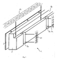
- fig. 1
- shows an isometric view of the foundation element,
- fig. 2
- shows a foundation element seen in a horizontal section at column level,
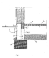
- fig. 3
- shows a foundation element in cross-section, incorporated in a building structure,
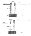
- fig. 4
- shows a foundation element for a load-bearing rear wall and a front wall with a load, where the load-bearing beams have their upper sides at the same level,
- fig. 5
- shows a foundation element for a load-bearing rear wall and a front wall with a load, where the load-bearing beams have their upper sides at different levels,
- fig. 6
- shows an alternative embodiment of the foundation element, which is dimensioned for mounting on a point foundation.
- A foundation element according to the invention is shown in
figures 1 - 6 . -
Figure 1 shows an isometric drawing of the various construction parts which are included in an embodiment of a foundation element 1 according to the invention, in which afront plate 2, aninsulation element 3 and areinforcement 4a, 4b are shown separately. Theinsulation element 3 is made e.g. of polystyrene. It is indicated by arrows how the parts are to be mounted and thereby cooperate in a finished foundation element 1. Thefront plate 2 may be of soft-cast fibre concrete, fibre-reinforced plaster or another suitable plate material which is provided with dowels 8 (figure 2 ). When theinsulation element 3 is mounted subsequently on thefront plate 2, this takes place in that thedowels 8 pass through theinsulation element 3 to therecesses reinforcement 4a forcolumns 6 and the reinforcement 4b forbeams 7 are to be mounted, and thedowels 8 are then secured in theserecesses insulation element 3 both during transport and during the further mounting at the construction site. Thecolumn reinforcement 4a extends right into therecess 5b of theinsulation element 3 to thebeam 7 and is connected with the reinforcement 4b for thebeam 7, so thatcolumns 6 andbeams 7 are statically connected in the cast foundation element 1. Thereinforcement 4a, 4b forcolumns 6 andbeams 7 are secured against theinsulation element 3, so that the foundation element 1 may be transported as a whole to the construction site and be positioned on thebase foundation 10 directly from the truck. - A cast foundation element 1 with a horizontal section below the lower side of the beam through the
columns 6 is shown infigure 2 , from which it appears clearly that thedowels 8 of thefront plate 2 extend through theinsulation element 3 and out into the recesses 5 to thecolumn reinforcement 4a. where the ends of thedowels 8 are embedded in thecolumns 6 and/or thebeam 7 in connection with the subsequent mounting and casting. - The assembled reinforced foundation element is thus intended to be mounted at the site of its use on top of the
precast base foundation 10, in whichdowels 9 are secured corresponding tocolumns 6. Thedowels 9 are connected /cast firmly to thecolumns 6 of the foundation element 1, which is indicated infigure 3 , in the subsequent depositing of concrete in thecolumns 6. When thecolumns 6 have been cast, the shuttering, which has e.g. been mounted on the foundation elements 1 at the delivery from the element factory, is removed. The connections between the foundation elements 1 are jointed e.g. by a mastic joint between thefront plates 2 and foaming between theinsulation elements 3, so that the connections between the foundation elements 1 are tight and insulating, it being possible to perform the jointing both before and after the casting of thecolumns 6. Adrain layer 12 and aninsulation 13 as well as reinforcement for a ground deck 11 are provided. Thebeams 7 and the ground deck 11 are then cast and preferably in one and the same operation. It is ensured hereby that the transition between the foundation 1 and the ground deck 11 is tight, and that the construction is thereby protected as best as possible against the ingress of radon. At the casting ofbeam 7 and ground deck 11, theinsulation 13 of the ground deck may serve as a permanent shuttering for thebeam 7. - Alternatively,
columns 6 and overlyingreinforced beams 7 may be cast in one and the same operation with the ground deck 11, which likewise ensures that the transition between these elements is tight, and that the construction is thereby protected as best as possible against the ingress of radon. - The foundation element 1 is intended to be disposed on a
precast base foundation 10, which may be a line foundation, as shown infigures 1 - 5 .Figure 6 shows an alternative embodiment of the foundation element 1, which is mounted on a point foundation 10', In this embodiment,columns 6 are present only at the point foundations 10', and thebeam 7 is moreover dimensioned more strongly, as it is dimensioned for a greater static impact. - The foundation element 1 is constructed such that there is a suitable layer of the
insulation element 3 between thefront plate 2 and the load-bearingcolumns 6 andbeams 7, as thermal bridges may be eliminated hereby. It has been found in practice that an insulation layer of about 100 mm in front of columns and beams is sufficient to avoid the occurrence of thermal bridges in the finished foundation or at the connection between the foundation and a ground deck 11 and/or walls. - Thus, the foundation element 1 according to the invention also uses the
insulation material 3 to minimize the amount of concrete. Instead of using unreinforced or reinforced structures in great thicknesses and consequently large amounts of concrete, reinforced structures with statically optimized dimensions are used here, and consequently smaller thicknesses and smaller amounts of concrete. - Thus, the foundation element 1 according to the invention minimizes the amount of concrete relative to the traditionally used in situ works with the same strength in all types of constructions. At the same time, the foundation element 1 provides a solution to the great insulation requirements which are made with respect to building constructions today. With the foundation elements 1, it is possible to use incorporated prefabricated welded reinforcement 4 to a great extent, so that the elements 1 arrive at the construction site with reinforcement 4. This will accelerate the production rate considerably at the construction site, it having been found that the foundation works may be finished in approximately half the time compared to traditionally built block structures or shuttered structures.
- The foundation element 1 according to the invention may be configured for all types of front structures, including faced structures and other structures, where load-bearing capacity is required in the foundation below the front covering, and in combinations of these (with both a load-bearing front wall and rear wall), just as the two load-bearing beams may be constructed with the upper sides of the beams at the same or at different levels (see
figures 4-5 ).
Claims (10)
- A foundation element (1) for mounting on a precast base foundation (10, 10'), characterized in that the foundation element (1) comprises a front plate (2), an insulation element (3) as well as a plurality of load-bearing columns (6) and beams (7), said insulation element (3) having vertical recesses (5a) in which a reinforcement (4a) is mounted, and in which a plurality of load-bearing concrete columns (6) may be cast, as well as one or more horizontal recesses (5b) along the upper edge of the insulation element (3), in which a reinforcement (4b) is likewise mounted, and in which one or more load-bearing concrete beams (7) may be cast.
- A foundation element according to claim 1, characterized in that the recesses (5a, 5b) are present on the side of the insulation element (3) which faces away from the front plate (2).
- A foundation element according to claim 2, characterized in that recesses (5a, 5b) are also provided on the side of the insulation element (3) which faces inwardly toward the front plate (2).
- A foundation element according to any one of claims 1 - 3, characterized in that the front plate (2) has dowels (8) which extend through the insulation element (3) to recesses (5a, 5b), wherein the dowels (8) secure the front plate (2) to the insulation element (3) with lock washers, and wherein the free end of the dowels (8) may be embedded in columns (6) and/or beams (7).
- A foundation element according to any one of claims 1-4, characterized in that the front plate (2) is preferably of soft-cast fibre concrete or fibre-reinforced render.
- A method of mounting a foundation element (1) according to claims 1 - 5, characterized in- that the foundation element (1) is mounted on a precast base foundation (10, 10'), wherein dowels (9) in the base foundation (10, 10') are disposed corresponding to columns (6) of the foundation element (1),- that load-bearing columns (6) are cast of concrete around a reinforcement (4a) in the recesses (5a) in the foundation element (1),- and that at least one load-bearing beam (7) is cast of concrete around at least one reinforcement (4b) in at least one horizontal recess (5b) along the upper edge of the insulation element (3),- said foundation element (1) being connected with the base foundation (10, 10') by embedding the dowels (9) in the reinforced load-bearing columns (6) of the foundation element (1).
- A method according to claim 6, characterized in that the columns (6) of the foundation element (1) are cast in a first step and then harden completely or partly, and that at least one beam (7) is then cast together with a ground deck (11) in one and the same operation.
- A method according to claim 6, characterized in that the columns (6) and beams (7) of the foundation element (1) are cast together with a ground deck (11) in one and the same operation.
- A method according to any one of claims 6-8, characterized in that the connections between the foundation elements (1) are sealed prior to the casting of the columns (6) or after the casting of the columns (6) and prior to the casting of beams (7) and ground deck (11).
- Use of a foundation element according to any one of claims 1-5, characterized in that the foundation element (1) may be used for structures having a load-bearing front wall and/or rear wall.
Applications Claiming Priority (2)
| Application Number | Priority Date | Filing Date | Title |
|---|---|---|---|
| DKPA200900259 | 2009-02-25 | ||
| DKPA200900633 | 2009-05-19 |
Publications (5)
| Publication Number | Publication Date |
|---|---|
| EP2241690A2 true EP2241690A2 (en) | 2010-10-20 |
| EP2241690A8 EP2241690A8 (en) | 2010-12-01 |
| EP2241690A3 EP2241690A3 (en) | 2011-03-02 |
| EP2241690B1 EP2241690B1 (en) | 2014-12-31 |
| EP2241690B8 EP2241690B8 (en) | 2015-02-25 |
Family
ID=42124217
Family Applications (1)
| Application Number | Title | Priority Date | Filing Date |
|---|---|---|---|
| EP10388004.3A Not-in-force EP2241690B8 (en) | 2009-02-25 | 2010-02-22 | Insulated foundation element for mounting on precast base foundation |
Country Status (2)
| Country | Link |
|---|---|
| EP (1) | EP2241690B8 (en) |
| DK (1) | DK2241690T5 (en) |
Cited By (4)
| Publication number | Priority date | Publication date | Assignee | Title |
|---|---|---|---|---|
| EP2405065A1 (en) * | 2010-11-19 | 2012-01-11 | Georg Koch | Insulating connection element for bearing compressive loads |
| WO2013000470A1 (en) * | 2011-06-28 | 2013-01-03 | Holm Oestergaard Hansen Thomas | Edge insulation structure |
| ITTO20130151A1 (en) * | 2013-02-25 | 2013-05-27 | Torino Politecnico | INSULATING STRUCTURAL ELEMENT FOR BUILDING CONSTRUCTION. |
| EP2871297A1 (en) * | 2013-10-02 | 2015-05-13 | E G Bygg AB | Building structure comprising an energy efficient foundation structure and a method of forming a foundation structure |
Citations (6)
| Publication number | Priority date | Publication date | Assignee | Title |
|---|---|---|---|---|
| WO1991009180A1 (en) * | 1988-12-12 | 1991-06-27 | Vaessmar Lars Goeran | Edge element |
| US5596855A (en) * | 1994-11-14 | 1997-01-28 | Batch; Juan R. | Insitu insulated concrete wall structure |
| US5803669A (en) * | 1996-01-16 | 1998-09-08 | Bullard; Waymon | Thermal-insulated concrete forming system |
| DE202004005226U1 (en) * | 2004-04-02 | 2004-08-19 | Massiv-Elementebau A.R.T.U.S. Gmbh | Building foundation with thermal insulation includes bottom slab, intervening sealing sheet and recyclable insulation layer |
| GB2425318A (en) * | 2005-04-20 | 2006-10-25 | Ultraframe Uk Ltd | Formation for building foundation |
| WO2007046718A2 (en) * | 2005-10-19 | 2007-04-26 | Craig Wallace Lonsdale | Concrete floor system, incorporating foundation footing |
-
2010
- 2010-02-22 DK DK10388004.3T patent/DK2241690T5/en active
- 2010-02-22 EP EP10388004.3A patent/EP2241690B8/en not_active Not-in-force
Patent Citations (6)
| Publication number | Priority date | Publication date | Assignee | Title |
|---|---|---|---|---|
| WO1991009180A1 (en) * | 1988-12-12 | 1991-06-27 | Vaessmar Lars Goeran | Edge element |
| US5596855A (en) * | 1994-11-14 | 1997-01-28 | Batch; Juan R. | Insitu insulated concrete wall structure |
| US5803669A (en) * | 1996-01-16 | 1998-09-08 | Bullard; Waymon | Thermal-insulated concrete forming system |
| DE202004005226U1 (en) * | 2004-04-02 | 2004-08-19 | Massiv-Elementebau A.R.T.U.S. Gmbh | Building foundation with thermal insulation includes bottom slab, intervening sealing sheet and recyclable insulation layer |
| GB2425318A (en) * | 2005-04-20 | 2006-10-25 | Ultraframe Uk Ltd | Formation for building foundation |
| WO2007046718A2 (en) * | 2005-10-19 | 2007-04-26 | Craig Wallace Lonsdale | Concrete floor system, incorporating foundation footing |
Cited By (9)
| Publication number | Priority date | Publication date | Assignee | Title |
|---|---|---|---|---|
| EP2405065A1 (en) * | 2010-11-19 | 2012-01-11 | Georg Koch | Insulating connection element for bearing compressive loads |
| EP2455557A1 (en) | 2010-11-19 | 2012-05-23 | Georg Koch | Connection element for transferring pressure |
| EP2455556A1 (en) | 2010-11-19 | 2012-05-23 | Georg Koch | Insulating connection element for transferring compression |
| US8590241B2 (en) | 2010-11-19 | 2013-11-26 | TebeTec AG | Compressive force transmitting connection element |
| US8733050B2 (en) | 2010-11-19 | 2014-05-27 | TebeTec AG | Compressive force transmitting connection element |
| WO2013000470A1 (en) * | 2011-06-28 | 2013-01-03 | Holm Oestergaard Hansen Thomas | Edge insulation structure |
| ITTO20130151A1 (en) * | 2013-02-25 | 2013-05-27 | Torino Politecnico | INSULATING STRUCTURAL ELEMENT FOR BUILDING CONSTRUCTION. |
| WO2014128741A1 (en) * | 2013-02-25 | 2014-08-28 | Politecnico Di Torino | Structural insulating element for building constructions |
| EP2871297A1 (en) * | 2013-10-02 | 2015-05-13 | E G Bygg AB | Building structure comprising an energy efficient foundation structure and a method of forming a foundation structure |
Also Published As
| Publication number | Publication date |
|---|---|
| EP2241690B8 (en) | 2015-02-25 |
| DK2241690T3 (en) | 2015-07-13 |
| DK2241690T5 (en) | 2015-08-10 |
| EP2241690A3 (en) | 2011-03-02 |
| EP2241690A8 (en) | 2010-12-01 |
| EP2241690B1 (en) | 2014-12-31 |
Similar Documents
| Publication | Publication Date | Title |
|---|---|---|
| EP0454690B1 (en) | Prefabricated building foundation element | |
| CN108138481B (en) | Prefabricated column and beam structure type | |
| US9487943B2 (en) | Component building system | |
| EP2241690B1 (en) | Insulated foundation element for mounting on precast base foundation | |
| JP3780816B2 (en) | Seismic isolation method for existing buildings | |
| US7124545B1 (en) | Tilt-up panel and method | |
| JP5865567B2 (en) | Connecting slab and its construction method | |
| JP2005105531A (en) | Foundation structure of building and its construction method | |
| JPH11148231A (en) | Assembled and laid building reinforcing structure, its reinforcing method, and base isolating construction method | |
| JP2915897B1 (en) | Building construction method | |
| CN114635503A (en) | Fair-faced concrete wall flexibly connected with concrete frame column and construction method | |
| JP3057466B2 (en) | How to build underground structures | |
| KR100992038B1 (en) | Architectural beam by filled concrete | |
| JP6684088B2 (en) | Seismic retrofitting structure and method for existing buildings | |
| JP7455931B1 (en) | Precast board manufacturing method and precast board | |
| JP4511080B2 (en) | Construction method of underground structure | |
| JP7231523B2 (en) | Concrete building and its construction method | |
| JP2001193290A (en) | Seismic isolation method for existing building | |
| JP2004197400A (en) | Construction method of earthquake-resistant wall | |
| JP3941899B2 (en) | Reinforced concrete beam and column members and construction method | |
| JP2579944Y2 (en) | Load-bearing wall assembly structure | |
| JPH07103620B2 (en) | Construction method for steel structure | |
| JP2004225291A (en) | Construction method of earthquake resisting wall | |
| JP2501709B2 (en) | Foundation structure | |
| JPH0337603B2 (en) |
Legal Events
| Date | Code | Title | Description |
|---|---|---|---|
| PUAI | Public reference made under article 153(3) epc to a published international application that has entered the european phase |
Free format text: ORIGINAL CODE: 0009012 |
|
| AK | Designated contracting states |
Kind code of ref document: A2 Designated state(s): AT BE BG CH CY CZ DE DK EE ES FI FR GB GR HR HU IE IS IT LI LT LU LV MC MK MT NL NO PL PT RO SE SI SK SM TR |
|
| AX | Request for extension of the european patent |
Extension state: AL BA RS |
|
| RAP1 | Party data changed (applicant data changed or rights of an application transferred) |
Owner name: KLAUS NIELSEN RADGIVENDE INGENIORFIRMA F.R.I. I/S |
|
| PUAL | Search report despatched |
Free format text: ORIGINAL CODE: 0009013 |
|
| AK | Designated contracting states |
Kind code of ref document: A3 Designated state(s): AT BE BG CH CY CZ DE DK EE ES FI FR GB GR HR HU IE IS IT LI LT LU LV MC MK MT NL NO PL PT RO SE SI SK SM TR |
|
| AX | Request for extension of the european patent |
Extension state: AL BA RS |
|
| RIC1 | Information provided on ipc code assigned before grant |
Ipc: E04B 1/76 20060101ALN20100830BHEP Ipc: E04B 1/16 20060101ALI20110126BHEP Ipc: E04B 1/00 20060101AFI20100507BHEP Ipc: E04B 5/32 20060101ALN20100830BHEP Ipc: E02D 27/02 20060101ALI20110126BHEP |
|
| 17P | Request for examination filed |
Effective date: 20110902 |
|
| RAP1 | Party data changed (applicant data changed or rights of an application transferred) |
Owner name: KLAUS NIELSEN RADGIVENDE INGENIOERFIRMA F.R.I. A/S |
|
| GRAP | Despatch of communication of intention to grant a patent |
Free format text: ORIGINAL CODE: EPIDOSNIGR1 |
|
| INTG | Intention to grant announced |
Effective date: 20140728 |
|
| GRAS | Grant fee paid |
Free format text: ORIGINAL CODE: EPIDOSNIGR3 |
|
| GRAA | (expected) grant |
Free format text: ORIGINAL CODE: 0009210 |
|
| AK | Designated contracting states |
Kind code of ref document: B1 Designated state(s): AT BE BG CH CY CZ DE DK EE ES FI FR GB GR HR HU IE IS IT LI LT LU LV MC MK MT NL NO PL PT RO SE SI SK SM TR |
|
| REG | Reference to a national code |
Ref country code: CH Ref legal event code: EP Ref country code: GB Ref legal event code: FG4D |
|
| REG | Reference to a national code |
Ref country code: IE Ref legal event code: FG4D |
|
| RAP2 | Party data changed (patent owner data changed or rights of a patent transferred) |
Owner name: HIBE A/S |
|
| REG | Reference to a national code |
Ref country code: AT Ref legal event code: REF Ref document number: 704508 Country of ref document: AT Kind code of ref document: T Effective date: 20150215 |
|
| REG | Reference to a national code |
Ref country code: DE Ref legal event code: R096 Ref document number: 602010021387 Country of ref document: DE Effective date: 20150219 |
|
| REG | Reference to a national code |
Ref country code: SE Ref legal event code: TRGR |
|
| PG25 | Lapsed in a contracting state [announced via postgrant information from national office to epo] |
Ref country code: FI Free format text: LAPSE BECAUSE OF FAILURE TO SUBMIT A TRANSLATION OF THE DESCRIPTION OR TO PAY THE FEE WITHIN THE PRESCRIBED TIME-LIMIT Effective date: 20141231 Ref country code: LT Free format text: LAPSE BECAUSE OF FAILURE TO SUBMIT A TRANSLATION OF THE DESCRIPTION OR TO PAY THE FEE WITHIN THE PRESCRIBED TIME-LIMIT Effective date: 20141231 Ref country code: NO Free format text: LAPSE BECAUSE OF FAILURE TO SUBMIT A TRANSLATION OF THE DESCRIPTION OR TO PAY THE FEE WITHIN THE PRESCRIBED TIME-LIMIT Effective date: 20150331 |
|
| REG | Reference to a national code |
Ref country code: NL Ref legal event code: VDEP Effective date: 20141231 |
|
| REG | Reference to a national code |
Ref country code: DE Ref legal event code: R081 Ref document number: 602010021387 Country of ref document: DE Owner name: HIBE A/S, DK Free format text: FORMER OWNER: KLAUS NIELSEN RADGIVENDE INGENIORFIRMA F.R.I. A/S, NIVA, DK Effective date: 20150326 |
|
| REG | Reference to a national code |
Ref country code: LT Ref legal event code: MG4D |
|
| PG25 | Lapsed in a contracting state [announced via postgrant information from national office to epo] |
Ref country code: HR Free format text: LAPSE BECAUSE OF FAILURE TO SUBMIT A TRANSLATION OF THE DESCRIPTION OR TO PAY THE FEE WITHIN THE PRESCRIBED TIME-LIMIT Effective date: 20141231 Ref country code: LV Free format text: LAPSE BECAUSE OF FAILURE TO SUBMIT A TRANSLATION OF THE DESCRIPTION OR TO PAY THE FEE WITHIN THE PRESCRIBED TIME-LIMIT Effective date: 20141231 Ref country code: GR Free format text: LAPSE BECAUSE OF FAILURE TO SUBMIT A TRANSLATION OF THE DESCRIPTION OR TO PAY THE FEE WITHIN THE PRESCRIBED TIME-LIMIT Effective date: 20150401 |
|
| REG | Reference to a national code |
Ref country code: AT Ref legal event code: MK05 Ref document number: 704508 Country of ref document: AT Kind code of ref document: T Effective date: 20141231 |
|
| PG25 | Lapsed in a contracting state [announced via postgrant information from national office to epo] |
Ref country code: NL Free format text: LAPSE BECAUSE OF FAILURE TO SUBMIT A TRANSLATION OF THE DESCRIPTION OR TO PAY THE FEE WITHIN THE PRESCRIBED TIME-LIMIT Effective date: 20141231 |
|
| REG | Reference to a national code |
Ref country code: DK Ref legal event code: EGE Effective date: 20150706 Ref country code: DK Ref legal event code: T3 Effective date: 20150706 |
|
| PG25 | Lapsed in a contracting state [announced via postgrant information from national office to epo] |
Ref country code: SK Free format text: LAPSE BECAUSE OF FAILURE TO SUBMIT A TRANSLATION OF THE DESCRIPTION OR TO PAY THE FEE WITHIN THE PRESCRIBED TIME-LIMIT Effective date: 20141231 Ref country code: RO Free format text: LAPSE BECAUSE OF FAILURE TO SUBMIT A TRANSLATION OF THE DESCRIPTION OR TO PAY THE FEE WITHIN THE PRESCRIBED TIME-LIMIT Effective date: 20141231 Ref country code: ES Free format text: LAPSE BECAUSE OF FAILURE TO SUBMIT A TRANSLATION OF THE DESCRIPTION OR TO PAY THE FEE WITHIN THE PRESCRIBED TIME-LIMIT Effective date: 20141231 Ref country code: CZ Free format text: LAPSE BECAUSE OF FAILURE TO SUBMIT A TRANSLATION OF THE DESCRIPTION OR TO PAY THE FEE WITHIN THE PRESCRIBED TIME-LIMIT Effective date: 20141231 |
|
| REG | Reference to a national code |
Ref country code: DK Ref legal event code: T5 Effective date: 20150804 |
|
| PG25 | Lapsed in a contracting state [announced via postgrant information from national office to epo] |
Ref country code: AT Free format text: LAPSE BECAUSE OF FAILURE TO SUBMIT A TRANSLATION OF THE DESCRIPTION OR TO PAY THE FEE WITHIN THE PRESCRIBED TIME-LIMIT Effective date: 20141231 Ref country code: PL Free format text: LAPSE BECAUSE OF FAILURE TO SUBMIT A TRANSLATION OF THE DESCRIPTION OR TO PAY THE FEE WITHIN THE PRESCRIBED TIME-LIMIT Effective date: 20141231 Ref country code: IS Free format text: LAPSE BECAUSE OF FAILURE TO SUBMIT A TRANSLATION OF THE DESCRIPTION OR TO PAY THE FEE WITHIN THE PRESCRIBED TIME-LIMIT Effective date: 20150430 |
|
| PG25 | Lapsed in a contracting state [announced via postgrant information from national office to epo] |
Ref country code: LU Free format text: LAPSE BECAUSE OF FAILURE TO SUBMIT A TRANSLATION OF THE DESCRIPTION OR TO PAY THE FEE WITHIN THE PRESCRIBED TIME-LIMIT Effective date: 20150222 |
|
| REG | Reference to a national code |
Ref country code: CH Ref legal event code: PL |
|
| REG | Reference to a national code |
Ref country code: DE Ref legal event code: R097 Ref document number: 602010021387 Country of ref document: DE |
|
| PG25 | Lapsed in a contracting state [announced via postgrant information from national office to epo] |
Ref country code: LI Free format text: LAPSE BECAUSE OF NON-PAYMENT OF DUE FEES Effective date: 20150228 Ref country code: MC Free format text: LAPSE BECAUSE OF FAILURE TO SUBMIT A TRANSLATION OF THE DESCRIPTION OR TO PAY THE FEE WITHIN THE PRESCRIBED TIME-LIMIT Effective date: 20141231 Ref country code: CH Free format text: LAPSE BECAUSE OF NON-PAYMENT OF DUE FEES Effective date: 20150228 Ref country code: EE Free format text: LAPSE BECAUSE OF FAILURE TO SUBMIT A TRANSLATION OF THE DESCRIPTION OR TO PAY THE FEE WITHIN THE PRESCRIBED TIME-LIMIT Effective date: 20141231 |
|
| PLBE | No opposition filed within time limit |
Free format text: ORIGINAL CODE: 0009261 |
|
| STAA | Information on the status of an ep patent application or granted ep patent |
Free format text: STATUS: NO OPPOSITION FILED WITHIN TIME LIMIT |
|
| REG | Reference to a national code |
Ref country code: IE Ref legal event code: MM4A |
|
| GBPC | Gb: european patent ceased through non-payment of renewal fee |
Effective date: 20150331 |
|
| REG | Reference to a national code |
Ref country code: FR Ref legal event code: ST Effective date: 20151030 |
|
| 26N | No opposition filed |
Effective date: 20151001 |
|
| PG25 | Lapsed in a contracting state [announced via postgrant information from national office to epo] |
Ref country code: IT Free format text: LAPSE BECAUSE OF FAILURE TO SUBMIT A TRANSLATION OF THE DESCRIPTION OR TO PAY THE FEE WITHIN THE PRESCRIBED TIME-LIMIT Effective date: 20141231 |
|
| PG25 | Lapsed in a contracting state [announced via postgrant information from national office to epo] |
Ref country code: GB Free format text: LAPSE BECAUSE OF NON-PAYMENT OF DUE FEES Effective date: 20150331 Ref country code: IE Free format text: LAPSE BECAUSE OF NON-PAYMENT OF DUE FEES Effective date: 20150222 |
|
| PG25 | Lapsed in a contracting state [announced via postgrant information from national office to epo] |
Ref country code: FR Free format text: LAPSE BECAUSE OF NON-PAYMENT OF DUE FEES Effective date: 20150302 Ref country code: SI Free format text: LAPSE BECAUSE OF FAILURE TO SUBMIT A TRANSLATION OF THE DESCRIPTION OR TO PAY THE FEE WITHIN THE PRESCRIBED TIME-LIMIT Effective date: 20141231 |
|
| PG25 | Lapsed in a contracting state [announced via postgrant information from national office to epo] |
Ref country code: BE Free format text: LAPSE BECAUSE OF FAILURE TO SUBMIT A TRANSLATION OF THE DESCRIPTION OR TO PAY THE FEE WITHIN THE PRESCRIBED TIME-LIMIT Effective date: 20141231 |
|
| PG25 | Lapsed in a contracting state [announced via postgrant information from national office to epo] |
Ref country code: MT Free format text: LAPSE BECAUSE OF FAILURE TO SUBMIT A TRANSLATION OF THE DESCRIPTION OR TO PAY THE FEE WITHIN THE PRESCRIBED TIME-LIMIT Effective date: 20141231 |
|
| PG25 | Lapsed in a contracting state [announced via postgrant information from national office to epo] |
Ref country code: HU Free format text: LAPSE BECAUSE OF FAILURE TO SUBMIT A TRANSLATION OF THE DESCRIPTION OR TO PAY THE FEE WITHIN THE PRESCRIBED TIME-LIMIT; INVALID AB INITIO Effective date: 20100222 Ref country code: BG Free format text: LAPSE BECAUSE OF FAILURE TO SUBMIT A TRANSLATION OF THE DESCRIPTION OR TO PAY THE FEE WITHIN THE PRESCRIBED TIME-LIMIT Effective date: 20141231 Ref country code: SM Free format text: LAPSE BECAUSE OF FAILURE TO SUBMIT A TRANSLATION OF THE DESCRIPTION OR TO PAY THE FEE WITHIN THE PRESCRIBED TIME-LIMIT Effective date: 20141231 |
|
| PG25 | Lapsed in a contracting state [announced via postgrant information from national office to epo] |
Ref country code: CY Free format text: LAPSE BECAUSE OF FAILURE TO SUBMIT A TRANSLATION OF THE DESCRIPTION OR TO PAY THE FEE WITHIN THE PRESCRIBED TIME-LIMIT Effective date: 20141231 |
|
| PG25 | Lapsed in a contracting state [announced via postgrant information from national office to epo] |
Ref country code: PT Free format text: LAPSE BECAUSE OF FAILURE TO SUBMIT A TRANSLATION OF THE DESCRIPTION OR TO PAY THE FEE WITHIN THE PRESCRIBED TIME-LIMIT Effective date: 20150501 |
|
| PG25 | Lapsed in a contracting state [announced via postgrant information from national office to epo] |
Ref country code: TR Free format text: LAPSE BECAUSE OF FAILURE TO SUBMIT A TRANSLATION OF THE DESCRIPTION OR TO PAY THE FEE WITHIN THE PRESCRIBED TIME-LIMIT Effective date: 20141231 |
|
| PG25 | Lapsed in a contracting state [announced via postgrant information from national office to epo] |
Ref country code: MK Free format text: LAPSE BECAUSE OF FAILURE TO SUBMIT A TRANSLATION OF THE DESCRIPTION OR TO PAY THE FEE WITHIN THE PRESCRIBED TIME-LIMIT Effective date: 20141231 |
|
| PGFP | Annual fee paid to national office [announced via postgrant information from national office to epo] |
Ref country code: DE Payment date: 20190227 Year of fee payment: 10 |
|
| PGFP | Annual fee paid to national office [announced via postgrant information from national office to epo] |
Ref country code: DK Payment date: 20190227 Year of fee payment: 10 Ref country code: SE Payment date: 20190227 Year of fee payment: 10 |
|
| REG | Reference to a national code |
Ref country code: DE Ref legal event code: R119 Ref document number: 602010021387 Country of ref document: DE |
|
| REG | Reference to a national code |
Ref country code: DK Ref legal event code: EBP Effective date: 20200229 |
|
| REG | Reference to a national code |
Ref country code: SE Ref legal event code: EUG |
|
| PG25 | Lapsed in a contracting state [announced via postgrant information from national office to epo] |
Ref country code: SE Free format text: LAPSE BECAUSE OF NON-PAYMENT OF DUE FEES Effective date: 20200223 |
|
| PG25 | Lapsed in a contracting state [announced via postgrant information from national office to epo] |
Ref country code: DE Free format text: LAPSE BECAUSE OF NON-PAYMENT OF DUE FEES Effective date: 20200901 Ref country code: DK Free format text: LAPSE BECAUSE OF NON-PAYMENT OF DUE FEES Effective date: 20200229 |