EP2244155A1 - Information processor - Google Patents
Information processor Download PDFInfo
- Publication number
- EP2244155A1 EP2244155A1 EP09710076A EP09710076A EP2244155A1 EP 2244155 A1 EP2244155 A1 EP 2244155A1 EP 09710076 A EP09710076 A EP 09710076A EP 09710076 A EP09710076 A EP 09710076A EP 2244155 A1 EP2244155 A1 EP 2244155A1
- Authority
- EP
- European Patent Office
- Prior art keywords
- hand
- protrusion
- user
- information processing
- processing device
- Prior art date
- Legal status (The legal status is an assumption and is not a legal conclusion. Google has not performed a legal analysis and makes no representation as to the accuracy of the status listed.)
- Granted
Links
Images


Classifications
-
- G—PHYSICS
- G06—COMPUTING; CALCULATING OR COUNTING
- G06F—ELECTRIC DIGITAL DATA PROCESSING
- G06F1/00—Details not covered by groups G06F3/00 - G06F13/00 and G06F21/00
- G06F1/16—Constructional details or arrangements
- G06F1/1613—Constructional details or arrangements for portable computers
- G06F1/1626—Constructional details or arrangements for portable computers with a single-body enclosure integrating a flat display, e.g. Personal Digital Assistants [PDAs]
-
- G—PHYSICS
- G06—COMPUTING; CALCULATING OR COUNTING
- G06F—ELECTRIC DIGITAL DATA PROCESSING
- G06F1/00—Details not covered by groups G06F3/00 - G06F13/00 and G06F21/00
- G06F1/16—Constructional details or arrangements
- G06F1/1613—Constructional details or arrangements for portable computers
- G06F1/1615—Constructional details or arrangements for portable computers with several enclosures having relative motions, each enclosure supporting at least one I/O or computing function
- G06F1/1616—Constructional details or arrangements for portable computers with several enclosures having relative motions, each enclosure supporting at least one I/O or computing function with folding flat displays, e.g. laptop computers or notebooks having a clamshell configuration, with body parts pivoting to an open position around an axis parallel to the plane they define in closed position
-
- G—PHYSICS
- G06—COMPUTING; CALCULATING OR COUNTING
- G06F—ELECTRIC DIGITAL DATA PROCESSING
- G06F1/00—Details not covered by groups G06F3/00 - G06F13/00 and G06F21/00
- G06F1/16—Constructional details or arrangements
- G06F1/1613—Constructional details or arrangements for portable computers
- G06F1/1633—Constructional details or arrangements of portable computers not specific to the type of enclosures covered by groups G06F1/1615 - G06F1/1626
- G06F1/1656—Details related to functional adaptations of the enclosure, e.g. to provide protection against EMI, shock, water, or to host detachable peripherals like a mouse or removable expansions units like PCMCIA cards, or to provide access to internal components for maintenance or to removable storage supports like CDs or DVDs, or to mechanically mount accessories
-
- A—HUMAN NECESSITIES
- A45—HAND OR TRAVELLING ARTICLES
- A45F—TRAVELLING OR CAMP EQUIPMENT: SACKS OR PACKS CARRIED ON THE BODY
- A45F2200/00—Details not otherwise provided for in A45F
- A45F2200/05—Holder or carrier for specific articles
- A45F2200/0525—Personal portable computing devices, e.g. laptop, tablet, netbook, game boy, navigation system, calculator
Definitions
- the present invention relates to a portable information processing device such as a notebook computer, and more particularly, to a portable information processing device having a belt allowing the user to hold it in one hand, thereby improving portability.
- a belt is generally also referred to as a suspending strap, a hand strap, or the like, and hereinafter uniformly referred to as a "hand strap".
- a notebook computer generally includes a rear casing for housing a notebook computer body, a keyboard as an input part, and other components, and a front casing for housing a flat display.
- the front casing is folded over the rear casing by a hinge part.
- Patent Documents 1 and 2 To solve this problem, it has been suggested (see, for example, Patent Documents 1 and 2) to provide a notebook computer with a hand strap on the rear surface of the rear casing, thereby allowing the user to slide one hand through the hand strap to securely hold the computer.
- the hand strap is a mere belt whose both ends are fixed to the rear casing of the notebook computer.
- the hand strap has too small a contact area with the back of the hand to allow the user to tightly hold the computer with the hand.
- the computer may wobble or slip from the hand, and the wobbling may cause the user to press wrong keys on the keyboard.
- the information processing device of the present invention includes a rear casing; a front casing facing the rear casing; a protrusion protruding outwardly on a surface of the rear casing; and a belt fixed to the rear casing so as to cover the protrusion.
- Fig. 1A is a perspective view of a notebook computer as the information processing device according to a first embodiment when seen from below, that is, from the rear side.
- Fig. 1B is a sectional view taken along a line A-A, which is parallel to the longitudinal direction of rear casing 13 of Fig. 1A .
- the notebook computer includes notebook computer body 10 formed of front casing 11 and rear casing 13 facing each other and connected openably and closably by hinge part 14.
- Front casing 11 houses a display part such as a liquid crystal display (not shown), and rear casing 13 houses a CPU, a HDD, and an input part such as keyboard 12.
- front casing 11 is in an open state so that the user can see the display on front casing 11.
- Rear casing 13 is provided on its rear surface 15 with belt (hereinafter, hand strap) 16, with which the user holds and supports computer body 10.
- Hand strap 16 is a substantially T-shaped belt fixed to rear casing 13 at three points: fixed parts 17a, 17b, and 17c, and is provided substantially at its center with substantially circular through hole 18.
- substantially T-shaped means that fixed part 17c is formed in a position perpendicular to the segment which is parallel to hinge part 14 and connects fixed parts 17a and 17b.
- Rear surface 15 has protrusion 19 with a substantially spherical surface as shown in Fig. 1B .
- Through hole 18 of hand strap 16 is formed in the position corresponding to top 19a of protrusion 19.
- Hand strap 16 is made of stretchable hard rubber or an elastic resin such as polybutylene terephthalate or elastomeric material.
- Rear surface 15 also has fixed-part positioning parts 20 in order to change the positions of fixed parts 17a, 17b, and 17c of hand strap 16 according to the size and desired position of the hand of the user, or in order to remove hand strap 16.
- Hand strap 16 has a pair of fixed ends 16a and 16b, which are engaged with fixed parts 17a and 17b, respectively. Fixed ends 16a and 16b are thicker than sliding part 16d through which the user slides the back of the hand.
- Fig. 2 is a perspective view of computer body 10 of the notebook computer as the information processing device according to the first embodiment when held in one hand.
- the user slides one hand 21 between hand strap 16 and rear surface 15 of computer body 10, and holds protrusion 19 having a spherical surface with the palm of one hand 21.
- third joints 22 of the index, middle, and annular fingers of one hand 21 protrude from through hole 18.
- the palm of one hand 21 is in contact with protrusion 19 in a large area
- the back of one hand 21 is in contact with hand strap 16 in a large area, thus establishing a firm contact between one hand 21 and computer body 10.
- the part of the back of one hand 21 that corresponds to protrusion 19 protrude from through hole 18. This reduces the incidence of compression and numbness of one hand 21.
- the friction force between the peripheral edge of through hole 18 and the back of one hand 21 exposed from through hole 18 assists the user to securely hold computer body 10 in a desired direction without extra force.
- hand strap 16 is substantially T-shaped in the present embodiment, the user can hold computer body 10 at an inclination of about 45 degrees with respect to one hand 21.
- the notebook computer allows the user to hold computer body 10 comfortably in one hand just in front of his/her face and to perform key inputs without feeling fatigue.
- hand strap 16 is substantially T-shaped to be fixed to rear surface 15 of computer body 10 at three points, and has substantially circular through hole 18 substantially at its center. This allows the user to position one hand 21 after sliding it between two adjacent fixed parts 17b and 17c to hold computer body 10. This also allows the user to limit the rotational degrees of freedom of one hand 21 by pressing third joints 22 and their vicinity on the back of one hand 21 protruding from through hole 18 against the outer periphery of through hole 18.
- the elastic force of hand strap 16 made of stretchable rubber, elastomeric material, or the like assists the user to further firmly hold computer body 10 in one hand 21.
- Hand strap 16 having the bilaterally symmetrical shape (T-shape) can be used by both right-handed and left-handed people. When sliding one hand 21 between adjacent fixed parts 17b and 17c of substantially T-shaped hand strap 16, the user can hold computer body 10 at an inclination of about 45 degrees on the palm of one hand 21. This results in an improvement in input operability and display visibility.
- the user when using the computer while standing, the user can firmly hold computer body 10 i n one hand without feeling fatigue, resulting in a reduction in the risk of dropping it, and hence, in an improvement in operability and visibility.
- fixed ends 16a and 16b of hand strap 16 are preferably thicker than sliding part 16d.
- the distance between rear surface 15 and the tips of fixed ends 16a and 16b can be larger than the distance between rear surface 15 and top 19a of protrusion 19 because of the following reason.
- sliding part 16d of hand strap 16 is an elastic body, and fixed ends 16a and 16b, which are also elastic bodies, are thicker than sliding part 16d so as to be rigid. Therefore, when computer body 10 is put on a flat desk, the back of computer body 10, that is, the hinge part 14 side of Fig. 1A becomes higher than the front side so that keyboard 12 can be tilted. With this structure, the compressive force applied by the user when pressing keys is absorbed in fixed ends 16a and 16b to improve operability. Furthermore, the elasticity of sliding part 16d absorbs the impact when computer body 10 is placed on the desk.
- fixed part 17c is engaged with fixed end 16c of hand strap 16, which is preferably as thick as sliding part 16d so that keyboard 12 is tilted as expected.
- fixed ends 16a, 16b, and 16c function as foot rubbers of computer body 10 for reducing the impact when it is placed on a flat surface.
- keyboard 12 can be tilted by satisfying the following three conditions.
- Fixed parts 17a and 17b are equal in height from rear surface 15 and larger in height than top 19a of protrusion 19; fixed part 17c is smaller in height from rear surface 15 than fixed parts 17a and 17b; and fixed parts 17a and 17b are provided with resin or metallic rims having a higher rigidity than hand strap 16. By making them of an elastic material, fixed parts 17a and 17b can be functioned as foot rubbers in the same manner as fixed ends 16a, 16b, and 16c.
- the information processing device allows the user to hold computer body 10 with the palm and back of one hand 21, leaving the thumb and fingers free. Therefore, the user can place the tips of the thumb and fingers on the surface having hinge part 14 as shown in Fig. 2 . This results in a further improvement in the stability of computer body 10 while it is being held. It is also possible that second auxiliary keys having the same function as the auxiliary keys on keyboard 12 are arranged in positions within the reach of fingertips so as to further improve operability.
- the information processing device allows the user to securely hold the computer body in one hand and to perform key inputs with the other hand, thereby improving operability and visibility.
- Figs. 3A and 3B show a second embodiment of a notebook computer.
- Fig. 3A is a perspective view of a notebook computer as the information processing device according to the second embodiment when held in one hand.
- Fig. 3B is a sectional view taken along a line B-B, which is parallel to the longitudinal direction of the rear casing of Fig. 3A .
- like components are labeled with like reference numerals with respect to Figs. 1A, 1B , and Fig. 2 , and hence the description thereof will be omitted.
- a notebook computer as the information processing device includes notebook computer body 101.
- computer body 101 is provided on rear surface 15 of rear casing 13 with protrusion 19 having a spherical surface similar to the one shown in Fig. 1B .
- the present embodiment includes hand strap 30 fixed at two points instead of hand strap 16 fixed at three points of the first embodiment.
- Hand strap 30 is a belt which has substantially oval through hole 31 in a position corresponding to top 19a of protrusion 19 and is fixed at both ends thereof to fixed parts 32a and 32b on rear surface 15. Through hole 31 can be formed in other shapes as long as it is large enough to allow the back of one hand 21 holding computer body 101 to project therefrom. Fixed parts 32a and 32b can be changed in position so as to adjust the length of hand strap 30 according to the size of one hand 21 and the angle at which the user wants to hold computer body 101.
- hand strap 30 is made of stretchable hard rubber or an elastic resin such as polybutylene terephthalate or elastomeric material.
- Hand strap 30 has fixed ends 30a and 30b, which are engaged with fixed parts 32a and 32b, respectively, on rear surface 15. Fixed ends 30a and 30b are thicker than sliding part 30c through which the user slide the back of the hand. The height of fixed ends 30a and 30b from rear surface 15 to their tips is larger than the height of protrusion 19 from rear surface 15 to top 19a.
- the following is a description of how to hold notebook computer body 101 of the present embodiment in one hand and to operate it with the other hand.
- the user slides one hand 21 between hand strap 30 and rear surface 15 of computer body 101, and holds protrusion 19 along its outer periphery with the palm of one hand 21.
- third joints 22 of the index, middle, and annular fingers project from through hole 31.
- the palm of one hand 21 is in contact with protrusion 19 in a large area
- the back of one hand 21 is in contact with hand strap 30 in a large area, thus establishing a firm contact between one hand 21 and computer body 101.
- Hand strap 30 used in the present embodiment which is a belt fixed at two points, occupies so small a space that it is suitable for use in, for example, compact portable information processing devices and game machines having a liquid crystal display of about 8.9 inches.
- the user presses protrusion 19 by the palm bent along the outer periphery of protrusion 19 while protruding third joints 22 of the index, middle, and annular fingers from through hole 31 with these fingers bent.
- the user can tightly hold computer body 101.
- the user can firmly hold computer body 101 in one hand 21, resulting in a reduction in the risk of dropping it.
- sliding part 30c of hand strap 30 made of rubber, elastomer, or the like bends and allows the tips of fixed ends 30a and 30b to come into contact with the flat surface of the desk.
- keyboard 12 is placed tilted on the desk so as to improve input operability and to make fixed ends 30a and 30b function as foot rubbers in the same manner as in the first embodiment.
- hand strap 30 has through hole 31 from which third joints 22 of one hand 21 project.
- the user can securely hold computer body 101 even at an inclination of about 45 degrees with respect to one hand 21.
- the notebook computer allows the user to hold computer body 101 comfortably in one hand just in front of his/her face, thereby improving operability in, for example, key input and display visibility.
- the information processing device allows the user to hold computer body 101 with the palm and back of the hand, leaving the thumb and fingers free. Therefore, the user can place the tips of the thumb and fingers on the surface having hinge part 14 (see Fig. 1A ) as shown in Fig. 3A . This results in a further improvement in the stability of computer body 101 while it is being held. It is also possible that second auxiliary keys having the same function as the auxiliary keys on keyboard 12 are arranged in positions within the reach of fingertips so as to further improve operability.
- the first and second embodiments have described information processing devices including front casing 11 having a display part and rear casing 13 having an input part, front and rear casings 11 and 13 being supported rotatably by hinge part 14.
- a third embodiment will describe an information processing device in which a display part and an input part are arranged in the same casing.
- Fig. 4 is a perspective view of the information processing device according to the third embodiment when seen from the front side.
- Fig. 5 is a perspective view of the information processing device when seen from the rear side.
- Fig. 6 is a sectional view taken along a line C-C of Fig. 5 .
- the information processing device includes display part 53 and operation buttons 55 on the front side.
- the information processing device can be, for example, a portable navigation system (hereinafter, NAVI), a personal digital assistant (hereinafter, PDA), or a game machine.
- NAVI 50 is formed of front casing 51 and rear casing 52, which are molded from a resin or the like.
- front casing 51 includes display part 53 such as a liquid crystal display for displaying visual information and operation buttons 55 or control buttons for controlling the visual information such as menu selection on the display screen.
- display part 53 such as a liquid crystal display for displaying visual information
- operation buttons 55 or control buttons for controlling the visual information such as menu selection on the display screen.
- molded rear casing 52 has substantially rectangular low surface area 56, and high surface area 57, which is contiguous with and is thicker than low surface area 56. On the boundary between low and high surface areas 56 and 57, there is provided inclined, stepped portion 58.
- High surface area 57 having a large thickness includes an internal space for housing, for example, batteries as the power supply of NAVI 50.
- rear casing 52 is provided on a side surface thereof with cover 59 opened for battery replacement or with a connection terminal of an external device such as a USB flash drive according to the need.
- High surface area 57 is provided substantially at its center with protrusion 60 having a spherical surface. Part of the bottom of protrusion 60 crosses stepped portion 58 and projects toward low surface area 56.
- High surface area 57 is further provided with hand strap 62, which covers protrusion 60 and has through hole 61 in a position facing top 60a of protrusion 60.
- Hand strap 62 is fixed at both ends thereof to rear casing 52 by fixed parts 63a and 63b.
- hand strap 62 is made of stretchable rubber or an elastic resin such as polybutylene terephthalate or elastomeric material.
- hand strap 62 includes fixed ends 62a and 62b, which are thicker than sliding part 62c through which the user slides the back of the hand.
- Fixed ends 62a and 62b are equal in height from high surface area 57, and larger in height than top 60a of protrusion 60 from high surface area 57.
- sliding part 62c of hand strap 62 is elastically deformed by the weight of NAVI 50 and flattened because it is thinner than fixed ends 62a and 62b.
- Fixed ends 62a and 62b are thicker than sliding part 62c so as to be rigid, and have an equal or larger height than top 60a of protrusion 60 from high surface area 57.
- NAVI 50 can be placed tilted securely on the desk.
- NAVI 50 can be placed tilted further securely on the desk by making fixed ends 62a and 62b lower from high surface area 57 toward low surface area 56 as shown in Fig. 5 .
- display part 53 is tilted to improve visibility and the operability of operation buttons 55.
- NAVI 50 When made of the same elastic material as sliding part 62c, fixed ends 62a and 62b perform the function as foot rubbers of NAVI 50. As a result, NAVI 50 does not receive a large impact when the user places rear casing 52 on a flat surface such as a desk, operates display part 53, or presses operation buttons 55, thus further improving operability.
- NAVI 50 The following is a description of how to hold NAVI 50 according to the present embodiment in one hand and to operate it with the other hand.
- the user slides one hand between hand strap 62 and rear casing 52 of NAVI 50, and holds protrusion 60 along its outer periphery with the palm of the hand while protruding the third joints of the index, middle, and annular fingers from through hole 61.
- the palm of the hand (see Fig. 3A ) holding NAVI 50 is in contact with protrusion 60 in a large area, and the back of the hand is in contact with hand strap 62 in a large area, thus establishing a firm contact between the hand and NAVI 50.
- Hand strap 62 used in the present embodiment which is a belt fixed at two points, occupies so small a space that it is suitable for use in, for example, further compact NAVIs and game machines.
- hand strap 62 is a mere single belt, there is little risk of NAVI 50 being dropped because the user can press protrusion 60 by the palm bent along the outer periphery of protrusion 60 while protruding the third joints of the index, middle, and annular fingers from through hole 61 with these fingers bent.
- NAVI 50 while standing, the user can hold it firmly and securely in one hand, resulting in a reduction in the risk of dropping it.
- NAVI 50 allows the user to hold it with the palm and back of one hand, leaving the thumb and fingers free. Therefore, the user can place the tips of the thumb and fingers on the top end surface of rear casing 52 in the same manner as in Fig. 3A . This results in a further improvement in the stability of NAVI 50 while it is being held. It is also possible that auxiliary buttons are arranged, for example, on a side surface within the reach of fingertips so as to further improve the operability of NAVI 50.
- hand strap 62 has through hole 61 from which third joints of one hand project.
- NAVI 50 allows the user to hold it comfortably in one hand just in front of his/her face, thereby improving operability in, for example, key input and the visibility of display part 53.
- rear casing 52 is provided on the rear surface with substantially rectangular low surface area 56, high surface area 57 contiguous with low surface area 56, and inclined stepped portion 58 on the boundary between low and high surface areas 56 and 57.
- Part of the bottom of protrusion 60 formed on high surface area 57 crosses stepped portion 58 and projects toward low surface area 56. This allows the user to place the part extending from third joints to the wrist of the hand on low surface area 56 when bending the palm of the hand along protrusion 60.
- the user is provided with a higher degree of freedom in adjusting the angle perpendicular to the palm holding NAVI 50, thereby feeling much less fatigue.
- Fig. 7 is a perspective view of an example, other than NAVI 50, of the information processing device according to the present third embodiment.
- NAVI 501 is identical to NAVI 50 of Fig. 4 except in having handle 64 on the upper end of NAVI 50, that is, above display part 53.
- Handle 64 includes grip 66 and space 65. The presence of handle 64 facilitates the portability of NAVI 501 and the transition from a state in which NAVI 501 is held in one hand using hand strap 62 to a state in which NAVI 501 is placed on the desk.
- the user can slide the thumb and fingers of the hand into space 65 to hold NAVI 501 more securely.
- NAVIs 50 and 501 allow the user to securely hold them in one hand slid between hand strap 62 and rear casing 52, and to operate operation buttons 55 with the other hand. This results in an improvement in operability and the visibility of display part 53.
- the third embodiment has described a NAVI, in which display part 53 and operation buttons 55 are arranged on the same side of the same casing.
- a fourth embodiment will describe a PDA, in which a keyboard is also arranged on the same side as the display part.
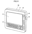
- Fig. 8 is a perspective view of PDA 80 according to the fourth embodiment when seen from the front side.
- Fig. 9 is a perspective view of PDA 801 as another example of the fourth embodiment.
- PDAs 80 and 801 according to the present embodiment are provided on the front side with display part 83, keyboard 84, and operation buttons 85.
- PDA 80 is formed of front casing 81 and rear casing 82, which are molded from a resin or the like.
- Front casing 81 includes display part 83 such as a liquid crystal display, keyboard 84 for input, and operation buttons 85 for controlling visual information such as menu selection on the display screen.
- display part 83 such as a liquid crystal display
- keyboard 84 for input
- operation buttons 85 for controlling visual information such as menu selection on the display screen.
- the user can perform all the operations of PDA 80 on the front side.
- PDA 801 includes, in addition to the structure of PDA 80 of Fig. 8 , handle 86 on the upper end of PDA 80, that is, above display part 83.
- Handle 86 includes grip 88 with space 87.
- Rear casing 82 of PDA 80 according to the present embodiment will be described using Figs. 5 and 6 because it has the same structure as rear casing 52 of NAVI 50 according to the third embodiment shown in Figs. 5 and. 6 .
- Rear casing 82 is provided on the rear surface with substantially rectangular low surface area 56, high surface area 57 contiguous with low surface area 56, and stepped portion 58 on the boundary between low and high surface areas 56 and 57.
- High surface area 57 having a large thickness includes an internal space for housing, for example, batteries as the power supply of PDA 80.
- rear casing 52 is provided on a side surface thereof with cover 89 opened for battery replacement or with a connection terminal of an external device such as a USB flash device.
- High surface area 57 is provided substantially at its center with protrusion 60 having a spherical surface. Part of the bottom of protrusion 60 crosses stepped portion 58 and projects toward low surface area 56.
- High surface area 57 is further provided with hand strap 62, which covers protrusion 60 and has through hole 61 in a position facing the top of protrusion 60.
- Hand strap 62 is fixed at both ends thereof to rear casing 52 by fixed parts 63a and 63b.
- Hand strap 62 is made of stretchable rubber or an elastic resin such as polybutylene terephthalate or elastomeric material.
- hand strap 62 includes fixed ends 62a and 62b, which are thicker than sliding part 62c through which the user slides the back of the hand. Fixed ends 62a and 62b are equal in height from high surface area 57, and larger in height than top 60a of protrusion 60 from high surface area 57.
- sliding part 62c of hand strap 62 is elastically deformed by the weight of PDA 80 and flattened because it is thinner than fixed ends 62a and 62b.
- Fixed ends 62a and 62b are thicker than sliding part 62c so as to be rigid, and have an equal or larger height than top 60a of protrusion 60 from high surface area 57.
- PDA 80 can be placed tilted securely on the desk.
- display part 83 is tilted to improve visibility and the operability of keyboard 84 and operation buttons 85.
- fixed ends 62a and 62b perform the function as foot rubbers of PDA 80 so as to absorb impact caused by a placing operation and/or an input operation, resulting in an improvement in stability and/or operability.
- Such an impact can be caused, for example, when the user places PDA 80 on a desk, operates display part 83, or presses keyboard 84 or operation buttons 85.
- the user slides one hand between hand strap 62 and rear casing 82 of PDA 80, and holds protrusion 60 along its outer periphery with the palm of the hand while protruding the third joints of the index, middle, and annular fingers from through hole 61.
- the palm of the hand (see Fig. 3A ) holding PDA 80 is in contact with protrusion 60 in a large area, and the back of the hand is in contact with hand strap 62 in a large area, thus establishing a firm contact between the hand and PDA 80.
- Hand strap 62 used in the present embodiment which is a belt fixed at two points, occupies so small a space that it is suitable for use in, for example, further compact PDAs and game machines.
- hand strap 62 used in the present embodiment is a mere single belt, there is little risk of PDA 80 being dropped while the user holds it with the hand slid between PDA 80 and hand strap 62. This is because the user can press protrusion 60 by the palm bent along the outer periphery of protrusion 60 while protruding the third joints of the index, middle, and annular fingers from through hole 61 with these fingers bent. Thus, when using PDA 80 while standing, the user can hold it firmly and securely with one hand, resulting in a reduction in the risk of dropping it.
- the user can hold PDA 80 with the palm and back of one hand, leaving the thumb and fingers free. Therefore, the user can place the tips of the thumb and fingers on the top end surface of rear casing 52 in the same manner as in Fig. 3A . This results in a further improvement in the stability of PDA 80 while it is being held. It is also possible that auxiliary buttons are arranged within the reach of fingertips so as to further improve operability.
- hand strap 62 has through hole 61 from which third joints of one hand project.
- PDA 80 allows the user to hold it comfortably in one hand just in front of his/her face, thereby improving operability in, for example, key input and the visibility of display part 83.
- rear casing 52 is provided on the rear surface with substantially rectangular low surface area 56, high surface area 57 contiguous with low surface area 56, and inclined stepped portion 58 on the boundary between low and high surface areas 56 and 57.
- Part of the bottom of protrusion 60 crosses stepped portion 58 and projects toward low surface area 56. This allows the user to place the part extending from third joints to the wrist of the hand on low surface area 56 when bending the palm of the hand along protrusion 60.
- the user is provided with a higher degree of freedom in adjusting the angle perpendicular to the palm holding PDA 80, thereby feeling much less fatigue.
- PDA 80 as the information processing device according to the present embodiment allows the user to securely hold it in one hand slid between hand strap 62 and rear casing 82, and to operate operation buttons 85 with the other hand. This results in an improvement in operability and the visibility of display part 83. In addition, when inputting from keyboard 84, the user can see display part 83 and operate keyboard 84 in a comfortable position.
- Fig. 9 is a perspective view of an example, other than PDA 80, of the information processing device according to the present fourth embodiment.
- PDA 801 is identical to PDA 80 of Fig. 8 except in having handle 86 on the upper end of PDA 80, that is, above display part 83.
- Handle 86 includes grip 88 and space 87.
- the presence of handle 86 facilitates the portability of PDA 801 and the transition from a state in which PDA 801 is held in one hand using hand strap 62 to a state in which PDA 801 is placed on the desk.
- the user can slide the thumb and fingers of the hand into space 87 to hole PDA 801 more securely.
- PDA 801 allows the user to securely hold it in one hand slid between hand strap 62 and rear casing 82, and to operate keyboard 84 and operation buttons 85 with the other hand. This results in an improvement in operability and the visibility of display part 83.
- the display part is arranged in the front casing together with the keyboard and the operation buttons, which is a controller for controlling display signals displayed on the display part.
- Such structures of the third and fourth embodiments can also be applied, besides NAVIs and PDAs, to game machines and portable terminals used, for example, by nurses for inventory management or patient nursing care.
- the controller can be applied, besides control buttons, to a touch panel.
- the information processing device of the present invention is particularly suitable for use in portable information processing devices because it allows the user to hold it firmly and securely in one hand, and to operate it with the other hand, thereby improving operability in, for example, key input.
Abstract
Description
- The present invention relates to a portable information processing device such as a notebook computer, and more particularly, to a portable information processing device having a belt allowing the user to hold it in one hand, thereby improving portability. Such a belt is generally also referred to as a suspending strap, a hand strap, or the like, and hereinafter uniformly referred to as a "hand strap".
- In recent years, highly portable information processing devices such as notebook computers have come into widespread use, and some of them have a hand strap to improve portability.
- A notebook computer generally includes a rear casing for housing a notebook computer body, a keyboard as an input part, and other components, and a front casing for housing a flat display. The front casing is folded over the rear casing by a hinge part.
- These notebook computers have been reduced in weight and size in recent years, allowing the user to hold and operate them while standing in more and more situations. The user holds edges of the casings of a notebook computer in one hand, and operates the keyboard with the other hand. It is not easy, however, for the user to operate the keyboard with one hand while precariously holding and supporting the computer in the other hand.
- To solve this problem, it has been suggested (see, for example, Patent Documents 1 and 2) to provide a notebook computer with a hand strap on the rear surface of the rear casing, thereby allowing the user to slide one hand through the hand strap to securely hold the computer.
- In the conventional structures shown in Patent Documents 1 and 2, however, the hand strap is a mere belt whose both ends are fixed to the rear casing of the notebook computer. The hand strap has too small a contact area with the back of the hand to allow the user to tightly hold the computer with the hand. As a result, the computer may wobble or slip from the hand, and the wobbling may cause the user to press wrong keys on the keyboard.
- It is preferable that when holding the notebook computer in one hand and operating the keyboard or the like with the other hand, the user can hold the computer inclined with respect to the hand holding the computer in terms of keyboard input and display visibility. In the conventional structures of the hand straps shown in Patent Documents 1 and 2, however, it is difficult for the user to securely hold the notebook computer in a state inclined with respect to the hand.
- Patent Document 1: Japanese Patent Unexamined Publication No.
2000-105630 - Patent Document 2: Japanese Patent Unexamined Publication No.
2007-102532 - The information processing device of the present invention includes a rear casing; a front casing facing the rear casing; a protrusion protruding outwardly on a surface of the rear casing; and a belt fixed to the rear casing so as to cover the protrusion.
- With this structure, when the user slides one hand between the rear casing and the belt and holds the protrusion with the palm of the hand, the compressive force of the belt allows the user to support the rear casing with the hand without feeling fatigue, and hence, to securely hold the notebook computer.
-
-
Fig. 1A is a perspective view of a notebook computer as the information processing device according to a first embodiment when seen from below, that is, from the rear side. -
Fig. 1B is a sectional view taken along a line A-A, which is parallel to the longitudinal direction ofrear casing 13 ofFig. 1A . -
Fig. 2 is a perspective view of the notebook computer as the information processing device according to the first embodiment when held in one hand. -
Fig. 3A is a perspective view of a notebook computer as the information processing device according to a second embodiment when held in one hand. -
Fig. 3B is a sectional view taken along a line B-B, which is parallel to the longitudinal direction of the rear casing ofFig. 3A . -
Fig. 4 is a perspective view of an information processing device according to a third embodiment when seen from the front side. -
Fig. 5 is a perspective view of the information processing device according to the third embodiment when seen from the rear side. -
Fig. 6 is a sectional view taken along a line C-C ofFig. 5 . -
Fig. 7 is a perspective view of another example of the information processing device according to the third embodiment. -
Fig. 8 is a perspective view of an information processing device according to a fourth embodiment when seen from the front side. -
Fig. 9 is a perspective view of another example of the information processing device according to the fourth embodiment. -
- 10, 101
- notebook computer body
- 11, 51, 81
- front casing
- 12, 84
- keyboard
- 13, 52, 82
- rear casing
- 14
- hinge part
- 15
- rear surface
- 16, 30, 62
- belt (hand strap)
- 16a, 16b, 16c, 30a, 30b, 62a, 62b
- fixed end
- 16d, 30c, 62c
- sliding part
- 17a, 17b, 17c, 32a, 32b, 63a, 63b
- fixed part
- 18, 31, 61
- through hole
- 19, 60
- protrusion
- 19a, 60a
- top
- 20
- fixed-part positioning parts
- 21
- one hand
- 22
- third joint
- 50, 501
- NAVI
- 53, 83
- display part
- 55, 85
- operation button
- 56
- low surface area
- 57
- high surface area
- 58
- stepped portion
- 59, 89
- cover
- 64, 86
- handle
- 65, 87
- space
- 66, 88
- grip
- 80, 801
- PDA
- Embodiments of the present invention will be described as follows with reference to drawings.
-
Fig. 1A is a perspective view of a notebook computer as the information processing device according to a first embodiment when seen from below, that is, from the rear side.Fig. 1B is a sectional view taken along a line A-A, which is parallel to the longitudinal direction ofrear casing 13 ofFig. 1A . The notebook computer includesnotebook computer body 10 formed offront casing 11 andrear casing 13 facing each other and connected openably and closably byhinge part 14.Front casing 11 houses a display part such as a liquid crystal display (not shown), andrear casing 13 houses a CPU, a HDD, and an input part such askeyboard 12. InFig. 1A ,front casing 11 is in an open state so that the user can see the display onfront casing 11. -
Rear casing 13 is provided on itsrear surface 15 with belt (hereinafter, hand strap) 16, with which the user holds and supportscomputer body 10.Hand strap 16 is a substantially T-shaped belt fixed torear casing 13 at three points: fixedparts hole 18. The term "substantially T-shaped" means thatfixed part 17c is formed in a position perpendicular to the segment which is parallel to hingepart 14 and connects fixedparts -
Rear surface 15 hasprotrusion 19 with a substantially spherical surface as shown inFig. 1B . Throughhole 18 ofhand strap 16 is formed in the position corresponding to top 19a ofprotrusion 19.Hand strap 16 is made of stretchable hard rubber or an elastic resin such as polybutylene terephthalate or elastomeric material.Rear surface 15 also has fixed-part positioning parts 20 in order to change the positions of fixedparts hand strap 16 according to the size and desired position of the hand of the user, or in order to removehand strap 16.Hand strap 16 has a pair of fixed ends 16a and 16b, which are engaged with fixedparts part 16d through which the user slides the back of the hand. - The following is a description of how to hold
notebook computer body 10 of the notebook computer according to the present embodiment in one hand and to operate it with the other hand.Fig. 2 is a perspective view ofcomputer body 10 of the notebook computer as the information processing device according to the first embodiment when held in one hand. - As shown in
Fig. 2 , the user slides onehand 21 betweenhand strap 16 andrear surface 15 ofcomputer body 10, and holdsprotrusion 19 having a spherical surface with the palm of onehand 21. At this moment,third joints 22 of the index, middle, and annular fingers of onehand 21 protrude from throughhole 18. As a result, the palm of onehand 21 is in contact withprotrusion 19 in a large area, and the back of onehand 21 is in contact withhand strap 16 in a large area, thus establishing a firm contact between onehand 21 andcomputer body 10. When onehand 21 is slid betweenhand strap 16 andrear surface 15, the part of the back of onehand 21 that corresponds to protrusion 19 protrude from throughhole 18. This reduces the incidence of compression and numbness of onehand 21. In addition, the friction force between the peripheral edge of throughhole 18 and the back of onehand 21 exposed from throughhole 18 assists the user to securely holdcomputer body 10 in a desired direction without extra force. - Since
hand strap 16 is substantially T-shaped in the present embodiment, the user can holdcomputer body 10 at an inclination of about 45 degrees with respect to onehand 21. Thus, the notebook computer allows the user to holdcomputer body 10 comfortably in one hand just in front of his/her face and to perform key inputs without feeling fatigue. - As described above,
hand strap 16 is substantially T-shaped to be fixed torear surface 15 ofcomputer body 10 at three points, and has substantially circular throughhole 18 substantially at its center. This allows the user to position onehand 21 after sliding it between two adjacentfixed parts computer body 10. This also allows the user to limit the rotational degrees of freedom of onehand 21 by pressingthird joints 22 and their vicinity on the back of onehand 21 protruding from throughhole 18 against the outer periphery of throughhole 18. The elastic force ofhand strap 16 made of stretchable rubber, elastomeric material, or the like assists the user to further firmly holdcomputer body 10 in onehand 21.Hand strap 16 having the bilaterally symmetrical shape (T-shape) can be used by both right-handed and left-handed people. When sliding onehand 21 between adjacentfixed parts hand strap 16, the user can holdcomputer body 10 at an inclination of about 45 degrees on the palm of onehand 21. This results in an improvement in input operability and display visibility. - Thus, when using the computer while standing, the user can firmly hold
computer body 10 i n one hand without feeling fatigue, resulting in a reduction in the risk of dropping it, and hence, in an improvement in operability and visibility. - As shown in
Fig. 1B , fixed ends 16a and 16b ofhand strap 16 are preferably thicker than slidingpart 16d. In addition, the distance betweenrear surface 15 and the tips of fixed ends 16a and 16b can be larger than the distance betweenrear surface 15 and top 19a ofprotrusion 19 because of the following reason. As described above, slidingpart 16d ofhand strap 16 is an elastic body, and fixed ends 16a and 16b, which are also elastic bodies, are thicker than slidingpart 16d so as to be rigid. Therefore, whencomputer body 10 is put on a flat desk, the back ofcomputer body 10, that is, thehinge part 14 side ofFig. 1A becomes higher than the front side so thatkeyboard 12 can be tilted. With this structure, the compressive force applied by the user when pressing keys is absorbed in fixed ends 16a and 16b to improve operability. Furthermore, the elasticity of slidingpart 16d absorbs the impact whencomputer body 10 is placed on the desk. - In this case, fixed
part 17c is engaged with fixedend 16c ofhand strap 16, which is preferably as thick as slidingpart 16d so thatkeyboard 12 is tilted as expected. With this structure, fixed ends 16a, 16b, and 16c function as foot rubbers ofcomputer body 10 for reducing the impact when it is placed on a flat surface. - Alternatively,
keyboard 12 can be tilted by satisfying the following three conditions.Fixed parts rear surface 15 and larger in height than top 19a ofprotrusion 19; fixedpart 17c is smaller in height fromrear surface 15 than fixedparts parts hand strap 16. By making them of an elastic material, fixedparts - The information processing device according to the present embodiment allows the user to hold
computer body 10 with the palm and back of onehand 21, leaving the thumb and fingers free. Therefore, the user can place the tips of the thumb and fingers on the surface havinghinge part 14 as shown inFig. 2 . This results in a further improvement in the stability ofcomputer body 10 while it is being held. It is also possible that second auxiliary keys having the same function as the auxiliary keys onkeyboard 12 are arranged in positions within the reach of fingertips so as to further improve operability. - As described above, the information processing device according to the present embodiment allows the user to securely hold the computer body in one hand and to perform key inputs with the other hand, thereby improving operability and visibility.
-
Figs. 3A and 3B show a second embodiment of a notebook computer.Fig. 3A is a perspective view of a notebook computer as the information processing device according to the second embodiment when held in one hand.Fig. 3B is a sectional view taken along a line B-B, which is parallel to the longitudinal direction of the rear casing ofFig. 3A . InFigs. 3A and 3B , like components are labeled with like reference numerals with respect toFigs. 1A, 1B , andFig. 2 , and hence the description thereof will be omitted. - As shown in
Fig. 3A , a notebook computer as the information processing device according to the present embodiment includesnotebook computer body 101. In the same manner as in the first embodiment, as shown inFig. 3B ,computer body 101 is provided onrear surface 15 ofrear casing 13 withprotrusion 19 having a spherical surface similar to the one shown inFig. 1B . - The present embodiment includes
hand strap 30 fixed at two points instead ofhand strap 16 fixed at three points of the first embodiment.Hand strap 30 is a belt which has substantially oval throughhole 31 in a position corresponding to top 19a ofprotrusion 19 and is fixed at both ends thereof to fixedparts rear surface 15. Throughhole 31 can be formed in other shapes as long as it is large enough to allow the back of onehand 21 holdingcomputer body 101 to project therefrom.Fixed parts hand strap 30 according to the size of onehand 21 and the angle at which the user wants to holdcomputer body 101. Similar tohand strap 16 of the first embodiment,hand strap 30 is made of stretchable hard rubber or an elastic resin such as polybutylene terephthalate or elastomeric material. -
Hand strap 30 has fixed ends 30a and 30b, which are engaged with fixedparts rear surface 15. Fixed ends 30a and 30b are thicker than slidingpart 30c through which the user slide the back of the hand. The height of fixed ends 30a and 30b fromrear surface 15 to their tips is larger than the height ofprotrusion 19 fromrear surface 15 to top 19a. - The following is a description of how to hold
notebook computer body 101 of the present embodiment in one hand and to operate it with the other hand. The user slides onehand 21 betweenhand strap 30 andrear surface 15 ofcomputer body 101, and holdsprotrusion 19 along its outer periphery with the palm of onehand 21. At this moment,third joints 22 of the index, middle, and annular fingers project from throughhole 31. As a result, the palm of onehand 21 is in contact withprotrusion 19 in a large area, and the back of onehand 21 is in contact withhand strap 30 in a large area, thus establishing a firm contact between onehand 21 andcomputer body 101. When onehand 21 is slid betweenhand strap 30 andrear surface 15, the part of the back of onehand 21 that corresponds to protrusion 19 projects from throughhole 31. This reduces the incidence of compression and numbness of the hand. In addition, the friction force between the peripheral edge of throughhole 31 and the back of onehand 21 exposed from throughhole 31 assists the user to securely holdcomputer body 101 in a desired direction without extra force. -
Hand strap 30 used in the present embodiment, which is a belt fixed at two points, occupies so small a space that it is suitable for use in, for example, compact portable information processing devices and game machines having a liquid crystal display of about 8.9 inches. - In the present embodiment using
hand strap 30, which is a belt fixed at two points, the user pressesprotrusion 19 by the palm bent along the outer periphery ofprotrusion 19 while protrudingthird joints 22 of the index, middle, and annular fingers from throughhole 31 with these fingers bent. As a result, the user can tightly holdcomputer body 101. Thus, when using the computer while standing, the user can firmly holdcomputer body 101 in onehand 21, resulting in a reduction in the risk of dropping it. - When
computer body 101 is placed on a flat desk, slidingpart 30c ofhand strap 30 made of rubber, elastomer, or the like bends and allows the tips of fixed ends 30a and 30b to come into contact with the flat surface of the desk. As a result,keyboard 12 is placed tilted on the desk so as to improve input operability and to makefixed ends 30a and 30b function as foot rubbers in the same manner as in the first embodiment. - In the present second embodiment,
hand strap 30 has throughhole 31 from which third joints 22 of onehand 21 project. As a result, the user can securely holdcomputer body 101 even at an inclination of about 45 degrees with respect to onehand 21. Thus, the notebook computer allows the user to holdcomputer body 101 comfortably in one hand just in front of his/her face, thereby improving operability in, for example, key input and display visibility. - The information processing device according to the present embodiment allows the user to hold
computer body 101 with the palm and back of the hand, leaving the thumb and fingers free. Therefore, the user can place the tips of the thumb and fingers on the surface having hinge part 14 (seeFig. 1A ) as shown inFig. 3A . This results in a further improvement in the stability ofcomputer body 101 while it is being held. It is also possible that second auxiliary keys having the same function as the auxiliary keys onkeyboard 12 are arranged in positions within the reach of fingertips so as to further improve operability. - The first and second embodiments have described information processing devices including
front casing 11 having a display part andrear casing 13 having an input part, front andrear casings hinge part 14. A third embodiment, on the other hand, will describe an information processing device in which a display part and an input part are arranged in the same casing.Fig. 4 is a perspective view of the information processing device according to the third embodiment when seen from the front side.Fig. 5 is a perspective view of the information processing device when seen from the rear side.Fig. 6 is a sectional view taken along a line C-C ofFig. 5 . - As shown in
Figs. 4 ,5, and 6 , the information processing device according to the present embodiment includesdisplay part 53 andoperation buttons 55 on the front side. The information processing device can be, for example, a portable navigation system (hereinafter, NAVI), a personal digital assistant (hereinafter, PDA), or a game machine. In the present embodiment, a NAVI will be described as the information processing device.NAVI 50 is formed offront casing 51 andrear casing 52, which are molded from a resin or the like. As shown inFig. 4 ,front casing 51 includesdisplay part 53 such as a liquid crystal display for displaying visual information andoperation buttons 55 or control buttons for controlling the visual information such as menu selection on the display screen. Thus, the user can perform all the operations ofNAVI 50 on the front side. - As shown in
Fig. 5 , moldedrear casing 52 has substantially rectangularlow surface area 56, andhigh surface area 57, which is contiguous with and is thicker thanlow surface area 56. On the boundary between low andhigh surface areas portion 58.High surface area 57 having a large thickness includes an internal space for housing, for example, batteries as the power supply ofNAVI 50. In this case,rear casing 52 is provided on a side surface thereof withcover 59 opened for battery replacement or with a connection terminal of an external device such as a USB flash drive according to the need.High surface area 57 is provided substantially at its center withprotrusion 60 having a spherical surface. Part of the bottom ofprotrusion 60 crosses steppedportion 58 and projects towardlow surface area 56. -
High surface area 57 is further provided withhand strap 62, which coversprotrusion 60 and has throughhole 61 in a position facing top 60a ofprotrusion 60.Hand strap 62 is fixed at both ends thereof torear casing 52 by fixedparts -
Fixed parts hand strap 62. Similar to handstraps hand strap 62 is made of stretchable rubber or an elastic resin such as polybutylene terephthalate or elastomeric material. - As shown in
Fig. 6 ,hand strap 62 includes fixed ends 62a and 62b, which are thicker than slidingpart 62c through which the user slides the back of the hand. Fixed ends 62a and 62b are equal in height fromhigh surface area 57, and larger in height than top 60a ofprotrusion 60 fromhigh surface area 57. WhenNAVI 50 is placed on a flat desk, slidingpart 62c ofhand strap 62 is elastically deformed by the weight ofNAVI 50 and flattened because it is thinner than fixed ends 62a and 62b. Fixed ends 62a and 62b, on the other hand, are thicker than slidingpart 62c so as to be rigid, and have an equal or larger height than top 60a ofprotrusion 60 fromhigh surface area 57. As a result,NAVI 50 can be placed tilted securely on the desk.NAVI 50 can be placed tilted further securely on the desk by making fixed ends 62a and 62b lower fromhigh surface area 57 towardlow surface area 56 as shown inFig. 5 . Thus, whenNAVI 50 is placed on the desk,display part 53 is tilted to improve visibility and the operability ofoperation buttons 55. - When made of the same elastic material as sliding
part 62c, fixed ends 62a and 62b perform the function as foot rubbers ofNAVI 50. As a result,NAVI 50 does not receive a large impact when the user placesrear casing 52 on a flat surface such as a desk, operatesdisplay part 53, or pressesoperation buttons 55, thus further improving operability. - The following is a description of how to hold
NAVI 50 according to the present embodiment in one hand and to operate it with the other hand. The user slides one hand betweenhand strap 62 andrear casing 52 ofNAVI 50, and holdsprotrusion 60 along its outer periphery with the palm of the hand while protruding the third joints of the index, middle, and annular fingers from throughhole 61. As a result, the palm of the hand (seeFig. 3A ) holdingNAVI 50 is in contact withprotrusion 60 in a large area, and the back of the hand is in contact withhand strap 62 in a large area, thus establishing a firm contact between the hand andNAVI 50. When the hand is slid betweenhand strap 62 andrear casing 52, the back of the hand corresponding to protrusion 60 projects from throughhole 61. This reduces the incidence of compression and numbness of the hand. In addition, the friction force between the peripheral edge of throughhole 61 and the back of the hand exposed from throughhole 61 assists the user to securely holdNAVI 50 in a desired direction without extra force. -
Hand strap 62 used in the present embodiment, which is a belt fixed at two points, occupies so small a space that it is suitable for use in, for example, further compact NAVIs and game machines. - Although
hand strap 62 is a mere single belt, there is little risk ofNAVI 50 being dropped because the user can pressprotrusion 60 by the palm bent along the outer periphery ofprotrusion 60 while protruding the third joints of the index, middle, and annular fingers from throughhole 61 with these fingers bent. Thus, when usingNAVI 50 while standing, the user can hold it firmly and securely in one hand, resulting in a reduction in the risk of dropping it. -
NAVI 50 allows the user to hold it with the palm and back of one hand, leaving the thumb and fingers free. Therefore, the user can place the tips of the thumb and fingers on the top end surface ofrear casing 52 in the same manner as inFig. 3A . This results in a further improvement in the stability ofNAVI 50 while it is being held. It is also possible that auxiliary buttons are arranged, for example, on a side surface within the reach of fingertips so as to further improve the operability ofNAVI 50. - In the present embodiment,
hand strap 62 has throughhole 61 from which third joints of one hand project. As a result, the user can securely holdNAVI 50 at an arbitrary inclination (for example, 45 degrees) with respect to the hand. Thus,NAVI 50 allows the user to hold it comfortably in one hand just in front of his/her face, thereby improving operability in, for example, key input and the visibility ofdisplay part 53. - In the present embodiment,
rear casing 52 is provided on the rear surface with substantially rectangularlow surface area 56,high surface area 57 contiguous withlow surface area 56, and inclined steppedportion 58 on the boundary between low andhigh surface areas protrusion 60 formed onhigh surface area 57 crosses steppedportion 58 and projects towardlow surface area 56. This allows the user to place the part extending from third joints to the wrist of the hand onlow surface area 56 when bending the palm of the hand alongprotrusion 60. As a result, the user is provided with a higher degree of freedom in adjusting the angle perpendicular to thepalm holding NAVI 50, thereby feeling much less fatigue. -
Fig. 7 is a perspective view of an example, other thanNAVI 50, of the information processing device according to the present third embodiment. InFig. 7 ,NAVI 501 is identical toNAVI 50 ofFig. 4 except in havinghandle 64 on the upper end ofNAVI 50, that is, abovedisplay part 53.Handle 64 includesgrip 66 andspace 65. The presence ofhandle 64 facilitates the portability ofNAVI 501 and the transition from a state in whichNAVI 501 is held in one hand usinghand strap 62 to a state in whichNAVI 501 is placed on the desk. When holdingrear casing 52 in one hand as mentioned above, the user can slide the thumb and fingers of the hand intospace 65 to holdNAVI 501 more securely. - As described above,
NAVIs hand strap 62 andrear casing 52, and to operateoperation buttons 55 with the other hand. This results in an improvement in operability and the visibility ofdisplay part 53. - The third embodiment has described a NAVI, in which display
part 53 andoperation buttons 55 are arranged on the same side of the same casing. A fourth embodiment, on the other hand, will describe a PDA, in which a keyboard is also arranged on the same side as the display part.Fig. 8 is a perspective view ofPDA 80 according to the fourth embodiment when seen from the front side.Fig. 9 is a perspective view ofPDA 801 as another example of the fourth embodiment. As shown inFigs. 8 and9 ,PDAs display part 83,keyboard 84, andoperation buttons 85. - As shown in
Fig. 8 ,PDA 80 is formed offront casing 81 andrear casing 82, which are molded from a resin or the like.Front casing 81 includesdisplay part 83 such as a liquid crystal display,keyboard 84 for input, andoperation buttons 85 for controlling visual information such as menu selection on the display screen. Thus, the user can perform all the operations ofPDA 80 on the front side. As shown inFig. 9 ,PDA 801 includes, in addition to the structure ofPDA 80 ofFig. 8 , handle 86 on the upper end ofPDA 80, that is, abovedisplay part 83.Handle 86 includesgrip 88 withspace 87. - Rear casing 82 of
PDA 80 according to the present embodiment will be described usingFigs. 5 and 6 because it has the same structure asrear casing 52 ofNAVI 50 according to the third embodiment shown inFigs. 5 and. 6 . -
Rear casing 82 is provided on the rear surface with substantially rectangularlow surface area 56,high surface area 57 contiguous withlow surface area 56, and steppedportion 58 on the boundary between low andhigh surface areas High surface area 57 having a large thickness includes an internal space for housing, for example, batteries as the power supply ofPDA 80. In this case,rear casing 52 is provided on a side surface thereof withcover 89 opened for battery replacement or with a connection terminal of an external device such as a USB flash device.High surface area 57 is provided substantially at its center withprotrusion 60 having a spherical surface. Part of the bottom ofprotrusion 60 crosses steppedportion 58 and projects towardlow surface area 56. -
High surface area 57 is further provided withhand strap 62, which coversprotrusion 60 and has throughhole 61 in a position facing the top ofprotrusion 60.Hand strap 62 is fixed at both ends thereof torear casing 52 by fixedparts -
Fixed parts hand strap 62.Hand strap 62 is made of stretchable rubber or an elastic resin such as polybutylene terephthalate or elastomeric material. - As shown in
Fig. 6 ,hand strap 62 includes fixed ends 62a and 62b, which are thicker than slidingpart 62c through which the user slides the back of the hand. Fixed ends 62a and 62b are equal in height fromhigh surface area 57, and larger in height than top 60a ofprotrusion 60 fromhigh surface area 57. WhenPDA 80 is placed on a flat desk, slidingpart 62c ofhand strap 62 is elastically deformed by the weight ofPDA 80 and flattened because it is thinner than fixed ends 62a and 62b. Fixed ends 62a and 62b, on the other hand, are thicker than slidingpart 62c so as to be rigid, and have an equal or larger height than top 60a ofprotrusion 60 fromhigh surface area 57. As a result,PDA 80 can be placed tilted securely on the desk. Thus, whenPDA 80 is placed on the desk,display part 83 is tilted to improve visibility and the operability ofkeyboard 84 andoperation buttons 85. - With this structure, fixed ends 62a and 62b perform the function as foot rubbers of
PDA 80 so as to absorb impact caused by a placing operation and/or an input operation, resulting in an improvement in stability and/or operability. Such an impact can be caused, for example, when the user placesPDA 80 on a desk, operatesdisplay part 83, or presseskeyboard 84 oroperation buttons 85. - The following is a description of how to hold
PDA 80 according to the present embodiment in one hand and to operate it with the other hand. The user slides one hand betweenhand strap 62 andrear casing 82 ofPDA 80, and holdsprotrusion 60 along its outer periphery with the palm of the hand while protruding the third joints of the index, middle, and annular fingers from throughhole 61. As a result, the palm of the hand (seeFig. 3A ) holdingPDA 80 is in contact withprotrusion 60 in a large area, and the back of the hand is in contact withhand strap 62 in a large area, thus establishing a firm contact between the hand andPDA 80. When the hand is slid betweenhand strap 62 andrear casing 82, the back of the hand corresponding to protrusion 60 projects from throughhole 61. This reduces the incidence of compression and numbness of the hand. In addition, the friction force between the peripheral edge of throughhole 61 and the back of the hand assists the user to securely holdPDA 80 in a desired direction without extra force. -
Hand strap 62 used in the present embodiment, which is a belt fixed at two points, occupies so small a space that it is suitable for use in, for example, further compact PDAs and game machines. - Although
hand strap 62 used in the present embodiment is a mere single belt, there is little risk ofPDA 80 being dropped while the user holds it with the hand slid betweenPDA 80 andhand strap 62. This is because the user can pressprotrusion 60 by the palm bent along the outer periphery ofprotrusion 60 while protruding the third joints of the index, middle, and annular fingers from throughhole 61 with these fingers bent. Thus, when usingPDA 80 while standing, the user can hold it firmly and securely with one hand, resulting in a reduction in the risk of dropping it. - The user can hold
PDA 80 with the palm and back of one hand, leaving the thumb and fingers free. Therefore, the user can place the tips of the thumb and fingers on the top end surface ofrear casing 52 in the same manner as inFig. 3A . This results in a further improvement in the stability ofPDA 80 while it is being held. It is also possible that auxiliary buttons are arranged within the reach of fingertips so as to further improve operability. - In the present embodiment,
hand strap 62 has throughhole 61 from which third joints of one hand project. As a result, the user can securely holdPDA 80 at an arbitrary inclination (for example, 45 degrees) with respect to the hand. Thus,PDA 80 allows the user to hold it comfortably in one hand just in front of his/her face, thereby improving operability in, for example, key input and the visibility ofdisplay part 83. - In the present embodiment,
rear casing 52 is provided on the rear surface with substantially rectangularlow surface area 56,high surface area 57 contiguous withlow surface area 56, and inclined steppedportion 58 on the boundary between low andhigh surface areas protrusion 60 crosses steppedportion 58 and projects towardlow surface area 56. This allows the user to place the part extending from third joints to the wrist of the hand onlow surface area 56 when bending the palm of the hand alongprotrusion 60. As a result, the user is provided with a higher degree of freedom in adjusting the angle perpendicular to thepalm holding PDA 80, thereby feeling much less fatigue. - As described above,
PDA 80 as the information processing device according to the present embodiment allows the user to securely hold it in one hand slid betweenhand strap 62 andrear casing 82, and to operateoperation buttons 85 with the other hand. This results in an improvement in operability and the visibility ofdisplay part 83. In addition, when inputting fromkeyboard 84, the user can seedisplay part 83 and operatekeyboard 84 in a comfortable position. -
Fig. 9 is a perspective view of an example, other thanPDA 80, of the information processing device according to the present fourth embodiment. InFig. 9 ,PDA 801 is identical toPDA 80 ofFig. 8 except in havinghandle 86 on the upper end ofPDA 80, that is, abovedisplay part 83.Handle 86 includesgrip 88 andspace 87. The presence ofhandle 86 facilitates the portability ofPDA 801 and the transition from a state in whichPDA 801 is held in one hand usinghand strap 62 to a state in whichPDA 801 is placed on the desk. When holdingrear casing 82 in one hand as mentioned above, the user can slide the thumb and fingers of the hand intospace 87 to holePDA 801 more securely. - As described above,
PDA 801 according to the present embodiment allows the user to securely hold it in one hand slid betweenhand strap 62 andrear casing 82, and to operatekeyboard 84 andoperation buttons 85 with the other hand. This results in an improvement in operability and the visibility ofdisplay part 83. - In the third and fourth embodiments, the display part is arranged in the front casing together with the keyboard and the operation buttons, which is a controller for controlling display signals displayed on the display part. Such structures of the third and fourth embodiments can also be applied, besides NAVIs and PDAs, to game machines and portable terminals used, for example, by nurses for inventory management or patient nursing care. The controller can be applied, besides control buttons, to a touch panel.
- The information processing device of the present invention is particularly suitable for use in portable information processing devices because it allows the user to hold it firmly and securely in one hand, and to operate it with the other hand, thereby improving operability in, for example, key input.
Claims (5)
- An information processing device comprising:a rear casing;a front casing facing the rear casing;a protrusion protruding outwardly on a surface of the rear casing; anda belt fixed to the rear casing so as to cover the protrusion.
- The information processing device of claim 1, wherein
the front casing includes:a display part for displaying visual information; anda control button for controlling the visual information. - The information processing device of claim 1, wherein
the belt has a through hole facing a top of the protrusion. - The information processing device of claim 1, wherein
a shape of the protrusion is a spherical surface. - The information processing device of one of claims 1 to 4, wherein
the rear surface includes:a low area which shapes a rectangular surface;a high area contiguous with the low area;a stepped portion at a boundary between the low area and the high area,the protrusion is formed in the high area; anda part of a bottom of the protrusion crosses the stepped portion so as to protrude toward the low area.
Applications Claiming Priority (2)
| Application Number | Priority Date | Filing Date | Title |
|---|---|---|---|
| JP2008034139 | 2008-02-15 | ||
| PCT/JP2009/000546 WO2009101800A1 (en) | 2008-02-15 | 2009-02-12 | Information processor |
Publications (3)
| Publication Number | Publication Date |
|---|---|
| EP2244155A1 true EP2244155A1 (en) | 2010-10-27 |
| EP2244155A4 EP2244155A4 (en) | 2013-10-23 |
| EP2244155B1 EP2244155B1 (en) | 2018-10-17 |
Family
ID=40956831
Family Applications (1)
| Application Number | Title | Priority Date | Filing Date |
|---|---|---|---|
| EP09710076.2A Active EP2244155B1 (en) | 2008-02-15 | 2009-02-12 | Information processor |
Country Status (4)
| Country | Link |
|---|---|
| US (1) | US8405981B2 (en) |
| EP (1) | EP2244155B1 (en) |
| JP (1) | JP4687821B2 (en) |
| WO (1) | WO2009101800A1 (en) |
Cited By (4)
| Publication number | Priority date | Publication date | Assignee | Title |
|---|---|---|---|---|
| US20110205696A1 (en) * | 2010-02-19 | 2011-08-25 | Panasonic Corporation | Electronic equipment provided with grip mechanism |
| CN102913722A (en) * | 2011-08-02 | 2013-02-06 | 瀚斯宝丽股份有限公司 | Suspension, supporting and holding structure integrated device |
| US8740270B1 (en) | 2010-06-09 | 2014-06-03 | John Mizell | Portable electronic device holder |
| WO2017178265A1 (en) * | 2016-04-12 | 2017-10-19 | Torsten Kehl | Mobile device, book, sleeve for same, holding device for holding the mobile device or the book, and method for producing same |
Families Citing this family (38)
| Publication number | Priority date | Publication date | Assignee | Title |
|---|---|---|---|---|
| US20140216954A1 (en) * | 2007-06-06 | 2014-08-07 | Belkin International, Inc. | Case for electrical device and method of using same |
| JP4980317B2 (en) * | 2008-08-22 | 2012-07-18 | パナソニック株式会社 | Information processing device |
| US20110267748A1 (en) * | 2010-04-28 | 2011-11-03 | Belkin International, Inc. | Case Configured to Removably Couple to a Portable Electrical Device and Method of Providing and Use Thereof |
| JP5163992B2 (en) * | 2010-06-04 | 2013-03-13 | Jb Trust株式会社 | carrying case |
| US9581291B2 (en) | 2010-07-29 | 2017-02-28 | Octa Llc | Positioning grip for a mobile electronic device |
| US9074725B2 (en) * | 2010-07-29 | 2015-07-07 | Kevin Trotsky | Mobile electronic device positioning unit |
| JP5681894B2 (en) | 2010-08-31 | 2015-03-11 | パナソニックIpマネジメント株式会社 | Electronic equipment |
| JP5623999B2 (en) * | 2010-08-31 | 2014-11-12 | パナソニック株式会社 | Electronic equipment |
| CA2714130A1 (en) * | 2010-08-31 | 2012-02-29 | Ervis Hyseni | Electronic device case gripper |
| US20120097831A1 (en) * | 2010-10-21 | 2012-04-26 | Lollygig LLC | Display device case, stand and accessory system |
| JP5645626B2 (en) * | 2010-12-06 | 2014-12-24 | キヤノン株式会社 | Display control apparatus, display control method, program, and storage medium |
| US9033384B2 (en) | 2011-03-09 | 2015-05-19 | Kernelope Holdings, Llc | Holding aid for a personal, hand-held, tablet-shaped device and methods of use |
| US8480144B2 (en) | 2011-03-09 | 2013-07-09 | Christine Potter | Holding aid for a personal, hand-held, tablet-shaped device and methods of use |
| JP5622328B2 (en) * | 2011-03-25 | 2014-11-12 | パナソニック株式会社 | Electronic device with gripping device |
| TW201305479A (en) * | 2011-07-25 | 2013-02-01 | Hannspree Inc | Device with hanging, supporting and holding structures |
| KR101209386B1 (en) * | 2011-07-29 | 2012-12-06 | 김영선 | Gripper structure of mobile terminal |
| KR101125325B1 (en) * | 2011-09-27 | 2012-03-27 | 정준엽 | Case for mobile device |
| JP2013131166A (en) * | 2011-12-22 | 2013-07-04 | Sony Corp | Electronic equipment |
| WO2013158057A1 (en) * | 2012-04-16 | 2013-10-24 | World Richman Manufacturing Corporation | Rotating mechanism for computer or similar device |
| JP6103422B2 (en) | 2012-08-23 | 2017-03-29 | パナソニックIpマネジメント株式会社 | Information processing device |
| KR101447457B1 (en) | 2012-08-31 | 2014-10-07 | (주)블루버드 | Tablet pc |
| EP2915416A4 (en) * | 2012-11-05 | 2016-11-02 | Gui Global Products Ltd | Devices and accessories employing a living hinge |
| TWI492026B (en) * | 2012-12-07 | 2015-07-11 | Twinhead Int Corp | Portable electronic device set |
| US20140166706A1 (en) * | 2012-12-17 | 2014-06-19 | Philip J Leisey-Bartsch | Electronic device case with rotating and sliding strap |
| US20140166707A1 (en) * | 2012-12-17 | 2014-06-19 | Philip J. Leisey-Bartsch | Apparatus with rotating disc for electronic devices and the like |
| JP5370600B1 (en) | 2013-02-01 | 2013-12-18 | 禪 定井 | Portable electronic terminal holder |
| JP5468696B2 (en) * | 2013-05-13 | 2014-04-09 | 株式会社ジョイパレット | Case for portable information terminal |
| GB201310408D0 (en) * | 2013-06-12 | 2013-07-24 | It Luggage Ltd | Improvement to an article of luggage |
| USD747321S1 (en) | 2013-07-02 | 2016-01-12 | Hand Held Products, Inc. | Electronic device enclosure |
| US9250652B2 (en) * | 2013-07-02 | 2016-02-02 | Hand Held Products, Inc. | Electronic device case |
| US9183526B2 (en) * | 2013-09-11 | 2015-11-10 | Oracle International Corporation | Metadata-driven audit reporting system that applies data security to audit data |
| JP6547935B2 (en) | 2013-12-25 | 2019-07-24 | パナソニックIpマネジメント株式会社 | Strap, electronic equipment |
| US9653934B2 (en) | 2014-02-23 | 2017-05-16 | Kathryn Celeste Forristall | Mobile device case with finger grips |
| US10849413B2 (en) | 2015-05-22 | 2020-12-01 | Havoc Tactical Solutions, LLC | Finger grip |
| JP6112495B1 (en) | 2016-02-19 | 2017-04-12 | パナソニックIpマネジメント株式会社 | Hand strap for electronic devices |
| JP6534109B1 (en) * | 2018-12-25 | 2019-06-26 | パナソニックIpマネジメント株式会社 | strap |
| US11219299B1 (en) * | 2020-08-11 | 2022-01-11 | Melissa Pimentel | Electronic tablet holder assembly |
| KR102376645B1 (en) * | 2021-11-03 | 2022-03-21 | 주식회사 나우로보틱스 | Teaching pendent |
Citations (3)
| Publication number | Priority date | Publication date | Assignee | Title |
|---|---|---|---|---|
| JP2000105630A (en) * | 1998-09-28 | 2000-04-11 | Matsushita Electric Ind Co Ltd | Portable computer |
| US6545667B1 (en) * | 1999-08-23 | 2003-04-08 | David M. Lilenfield | Apparatus for a convenient and comfortable cursor control device |
| US20040226973A1 (en) * | 2003-05-14 | 2004-11-18 | Adomax Technology Co., Ltd. | One-hand-holding aid for tablet personal computer |
Family Cites Families (25)
| Publication number | Priority date | Publication date | Assignee | Title |
|---|---|---|---|---|
| US3682352A (en) * | 1970-01-19 | 1972-08-08 | Theodore A Doucette | Detachable handle for cylindrical containers |
| US20070007353A1 (en) * | 1986-08-08 | 2007-01-11 | Danielson Arvin D | Laser scanner module having integral interface with hand-held data capture terminal, proximity and label sensing, and enhanced sensitivity and power efficiency |
| JPH0420168U (en) | 1990-06-07 | 1992-02-20 | ||
| US5339239A (en) * | 1989-10-13 | 1994-08-16 | Mitsubishi Plastics Industries Limited | Information collecting and/or service furnishing systems by which a user can request information from a central data base using a portable personal terminal and an access terminal |
| JPH0420168A (en) * | 1990-05-15 | 1992-01-23 | Oki Electric Ind Co Ltd | Facsimile communication equipment |
| US6266685B1 (en) * | 1991-07-11 | 2001-07-24 | Intermec Ip Corp. | Hand-held data collection system with stylus input |
| US5169191A (en) * | 1991-10-30 | 1992-12-08 | Benz Arthur F | Hand scoop for leaves and grass |
| US6049813A (en) * | 1993-02-26 | 2000-04-11 | Intermec Ip Corp. | Portable work station-type data collection system |
| US5479001A (en) * | 1994-07-22 | 1995-12-26 | Khyber Technologies Corporation | Right- and left-handed operable, grip-held pen computing device with removable data entry modules |
| JPH08123417A (en) * | 1994-10-25 | 1996-05-17 | Yamaha Corp | Grip type musical sound controller |
| US5779292A (en) * | 1994-12-30 | 1998-07-14 | Lucent Technologies Inc. | Manipulation aid for attachment to human body parts |
| WO1997004369A1 (en) * | 1995-07-22 | 1997-02-06 | Kuka Roboter Gmbh | Programming device |
| US6543695B1 (en) * | 1996-08-02 | 2003-04-08 | Symbol Technologies, Inc. | Housing for hand held scanner |
| JP2976964B2 (en) * | 1998-03-23 | 1999-11-10 | 松下電器産業株式会社 | Portable information terminal equipment |
| US6724618B1 (en) * | 2001-08-09 | 2004-04-20 | Symbol Technologies, Inc. | Housing for a portable electronic device |
| US7494064B2 (en) * | 2001-12-28 | 2009-02-24 | Symbol Technologies, Inc. | ASIC for supporting multiple functions of a portable data collection device |
| US7286803B2 (en) * | 2002-10-21 | 2007-10-23 | Matsushita Electric Industrial Co., Ltd. | Palm-sized mobile information terminal with finger-insertion hooking portion |
| JP2004164613A (en) * | 2002-10-21 | 2004-06-10 | Matsushita Electric Ind Co Ltd | Personal digital assistant |
| US20060011682A1 (en) * | 2004-07-06 | 2006-01-19 | Christensen Joseph W | Load stabilizing device |
| US7446753B2 (en) * | 2004-09-10 | 2008-11-04 | Hand Held Products, Inc. | Hand held computer device |
| JP2006251177A (en) * | 2005-03-09 | 2006-09-21 | Sony Corp | Holding device for imaging equipment |
| JP2007033941A (en) * | 2005-07-27 | 2007-02-08 | Olympus Imaging Corp | Portable imaging apparatus, and hand grip for portable imaging apparatus |
| JP2007102532A (en) | 2005-10-05 | 2007-04-19 | Matsushita Electric Ind Co Ltd | Hand strap for information processor |
| FR2896071A1 (en) | 2006-01-11 | 2007-07-13 | Airbus France Sas | METHOD AND DEVICE FOR AIDING THE CONTROL OF AN AIRCRAFT DURING AN AUTONOMOUS APPROACH |
| US7950980B2 (en) * | 2006-10-19 | 2011-05-31 | Medela Holding Ag | System and device for supporting a breast shield |
-
2009
- 2009-02-12 WO PCT/JP2009/000546 patent/WO2009101800A1/en active Application Filing
- 2009-02-12 JP JP2009523095A patent/JP4687821B2/en active Active
- 2009-02-12 US US12/594,876 patent/US8405981B2/en active Active
- 2009-02-12 EP EP09710076.2A patent/EP2244155B1/en active Active
Patent Citations (3)
| Publication number | Priority date | Publication date | Assignee | Title |
|---|---|---|---|---|
| JP2000105630A (en) * | 1998-09-28 | 2000-04-11 | Matsushita Electric Ind Co Ltd | Portable computer |
| US6545667B1 (en) * | 1999-08-23 | 2003-04-08 | David M. Lilenfield | Apparatus for a convenient and comfortable cursor control device |
| US20040226973A1 (en) * | 2003-05-14 | 2004-11-18 | Adomax Technology Co., Ltd. | One-hand-holding aid for tablet personal computer |
Non-Patent Citations (1)
| Title |
|---|
| See also references of WO2009101800A1 * |
Cited By (5)
| Publication number | Priority date | Publication date | Assignee | Title |
|---|---|---|---|---|
| US20110205696A1 (en) * | 2010-02-19 | 2011-08-25 | Panasonic Corporation | Electronic equipment provided with grip mechanism |
| US8243444B2 (en) * | 2010-02-19 | 2012-08-14 | Panasonic Corporation | Electronic equipment provided with grip mechanism |
| US8740270B1 (en) | 2010-06-09 | 2014-06-03 | John Mizell | Portable electronic device holder |
| CN102913722A (en) * | 2011-08-02 | 2013-02-06 | 瀚斯宝丽股份有限公司 | Suspension, supporting and holding structure integrated device |
| WO2017178265A1 (en) * | 2016-04-12 | 2017-10-19 | Torsten Kehl | Mobile device, book, sleeve for same, holding device for holding the mobile device or the book, and method for producing same |
Also Published As
| Publication number | Publication date |
|---|---|
| US20100296235A1 (en) | 2010-11-25 |
| US8405981B2 (en) | 2013-03-26 |
| JP4687821B2 (en) | 2011-05-25 |
| JPWO2009101800A1 (en) | 2011-06-09 |
| EP2244155B1 (en) | 2018-10-17 |
| WO2009101800A1 (en) | 2009-08-20 |
| EP2244155A4 (en) | 2013-10-23 |
Similar Documents
| Publication | Publication Date | Title |
|---|---|---|
| EP2244155B1 (en) | Information processor | |
| JP5270930B2 (en) | Electronic device with strap device | |
| US6967836B2 (en) | Device for accommodating a tablet PC | |
| US7428143B1 (en) | Tablet computer palette with extended bezel | |
| JP2009205531A5 (en) | ||
| US5831819A (en) | Hand-held data collection terminal with a contoured protrusion | |
| US20020126440A1 (en) | Miniature keyboard for a hand held computer | |
| WO2007014041A1 (en) | An apparatus for stabilizing an electronic device during data input and device control | |
| US20090289893A1 (en) | Finger appliance for data entry in electronic devices | |
| US20060133881A1 (en) | Mobile computing device form factor | |
| US20030043118A1 (en) | Compact keyboard for handheld computer | |
| US6898073B2 (en) | Hand-held electronic device | |
| TW201308050A (en) | Portable electronic device | |
| EP1227387A1 (en) | Notebook computer | |
| US20070036603A1 (en) | Portable keyboard | |
| US6773179B2 (en) | Input device | |
| EP2056657B1 (en) | Electronic devices with surface features | |
| JPH1115587A (en) | Notebook-type information processor | |
| JP2006024175A (en) | Mobile terminal and adapter | |
| US20180074604A1 (en) | Flat mouse and usage method thereof | |
| JP2000105630A (en) | Portable computer | |
| US20120050168A1 (en) | Handheld input device | |
| WO2004019597A1 (en) | Mobile phone with display disposed below the keyboard | |
| US8947360B2 (en) | Set of handheld adjustable panels of ergonomic keys and mouse | |
| JP3416934B2 (en) | Finger sack mouse |
Legal Events
| Date | Code | Title | Description |
|---|---|---|---|
| PUAI | Public reference made under article 153(3) epc to a published international application that has entered the european phase |
Free format text: ORIGINAL CODE: 0009012 |
|
| 17P | Request for examination filed |
Effective date: 20091019 |
|
| AK | Designated contracting states |
Kind code of ref document: A1 Designated state(s): AT BE BG CH CY CZ DE DK EE ES FI FR GB GR HR HU IE IS IT LI LT LU LV MC MK MT NL NO PL PT RO SE SI SK TR |
|
| AX | Request for extension of the european patent |
Extension state: AL BA RS |
|
| DAX | Request for extension of the european patent (deleted) | ||
| A4 | Supplementary search report drawn up and despatched |
Effective date: 20130923 |
|
| RIC1 | Information provided on ipc code assigned before grant |
Ipc: H05K 5/02 20060101ALI20130917BHEP Ipc: G06F 1/16 20060101AFI20130917BHEP |
|
| 17Q | First examination report despatched |
Effective date: 20160208 |
|
| STAA | Information on the status of an ep patent application or granted ep patent |
Free format text: STATUS: EXAMINATION IS IN PROGRESS |
|
| GRAP | Despatch of communication of intention to grant a patent |
Free format text: ORIGINAL CODE: EPIDOSNIGR1 |
|
| STAA | Information on the status of an ep patent application or granted ep patent |
Free format text: STATUS: GRANT OF PATENT IS INTENDED |
|
| INTG | Intention to grant announced |
Effective date: 20180507 |
|
| GRAS | Grant fee paid |
Free format text: ORIGINAL CODE: EPIDOSNIGR3 |
|
| GRAA | (expected) grant |
Free format text: ORIGINAL CODE: 0009210 |
|
| STAA | Information on the status of an ep patent application or granted ep patent |
Free format text: STATUS: THE PATENT HAS BEEN GRANTED |
|
| AK | Designated contracting states |
Kind code of ref document: B1 Designated state(s): AT BE BG CH CY CZ DE DK EE ES FI FR GB GR HR HU IE IS IT LI LT LU LV MC MK MT NL NO PL PT RO SE SI SK TR |
|
| REG | Reference to a national code |
Ref country code: GB Ref legal event code: FG4D |
|
| REG | Reference to a national code |
Ref country code: CH Ref legal event code: EP |
|
| REG | Reference to a national code |
Ref country code: IE Ref legal event code: FG4D |
|
| REG | Reference to a national code |
Ref country code: DE Ref legal event code: R096 Ref document number: 602009055093 Country of ref document: DE Ref country code: AT Ref legal event code: REF Ref document number: 1054759 Country of ref document: AT Kind code of ref document: T Effective date: 20181115 |
|
| REG | Reference to a national code |
Ref country code: NL Ref legal event code: MP Effective date: 20181017 |
|
| REG | Reference to a national code |
Ref country code: LT Ref legal event code: MG4D |
|
| REG | Reference to a national code |
Ref country code: AT Ref legal event code: MK05 Ref document number: 1054759 Country of ref document: AT Kind code of ref document: T Effective date: 20181017 |
|
| PG25 | Lapsed in a contracting state [announced via postgrant information from national office to epo] |
Ref country code: NL Free format text: LAPSE BECAUSE OF FAILURE TO SUBMIT A TRANSLATION OF THE DESCRIPTION OR TO PAY THE FEE WITHIN THE PRESCRIBED TIME-LIMIT Effective date: 20181017 |
|
| PG25 | Lapsed in a contracting state [announced via postgrant information from national office to epo] |
Ref country code: LT Free format text: LAPSE BECAUSE OF FAILURE TO SUBMIT A TRANSLATION OF THE DESCRIPTION OR TO PAY THE FEE WITHIN THE PRESCRIBED TIME-LIMIT Effective date: 20181017 Ref country code: HR Free format text: LAPSE BECAUSE OF FAILURE TO SUBMIT A TRANSLATION OF THE DESCRIPTION OR TO PAY THE FEE WITHIN THE PRESCRIBED TIME-LIMIT Effective date: 20181017 Ref country code: PL Free format text: LAPSE BECAUSE OF FAILURE TO SUBMIT A TRANSLATION OF THE DESCRIPTION OR TO PAY THE FEE WITHIN THE PRESCRIBED TIME-LIMIT Effective date: 20181017 Ref country code: BG Free format text: LAPSE BECAUSE OF FAILURE TO SUBMIT A TRANSLATION OF THE DESCRIPTION OR TO PAY THE FEE WITHIN THE PRESCRIBED TIME-LIMIT Effective date: 20190117 Ref country code: AT Free format text: LAPSE BECAUSE OF FAILURE TO SUBMIT A TRANSLATION OF THE DESCRIPTION OR TO PAY THE FEE WITHIN THE PRESCRIBED TIME-LIMIT Effective date: 20181017 Ref country code: NO Free format text: LAPSE BECAUSE OF FAILURE TO SUBMIT A TRANSLATION OF THE DESCRIPTION OR TO PAY THE FEE WITHIN THE PRESCRIBED TIME-LIMIT Effective date: 20190117 Ref country code: IS Free format text: LAPSE BECAUSE OF FAILURE TO SUBMIT A TRANSLATION OF THE DESCRIPTION OR TO PAY THE FEE WITHIN THE PRESCRIBED TIME-LIMIT Effective date: 20190217 Ref country code: ES Free format text: LAPSE BECAUSE OF FAILURE TO SUBMIT A TRANSLATION OF THE DESCRIPTION OR TO PAY THE FEE WITHIN THE PRESCRIBED TIME-LIMIT Effective date: 20181017 Ref country code: LV Free format text: LAPSE BECAUSE OF FAILURE TO SUBMIT A TRANSLATION OF THE DESCRIPTION OR TO PAY THE FEE WITHIN THE PRESCRIBED TIME-LIMIT Effective date: 20181017 Ref country code: FI Free format text: LAPSE BECAUSE OF FAILURE TO SUBMIT A TRANSLATION OF THE DESCRIPTION OR TO PAY THE FEE WITHIN THE PRESCRIBED TIME-LIMIT Effective date: 20181017 |
|
| PG25 | Lapsed in a contracting state [announced via postgrant information from national office to epo] |
Ref country code: SE Free format text: LAPSE BECAUSE OF FAILURE TO SUBMIT A TRANSLATION OF THE DESCRIPTION OR TO PAY THE FEE WITHIN THE PRESCRIBED TIME-LIMIT Effective date: 20181017 Ref country code: GR Free format text: LAPSE BECAUSE OF FAILURE TO SUBMIT A TRANSLATION OF THE DESCRIPTION OR TO PAY THE FEE WITHIN THE PRESCRIBED TIME-LIMIT Effective date: 20190118 Ref country code: PT Free format text: LAPSE BECAUSE OF FAILURE TO SUBMIT A TRANSLATION OF THE DESCRIPTION OR TO PAY THE FEE WITHIN THE PRESCRIBED TIME-LIMIT Effective date: 20190217 |
|
| REG | Reference to a national code |
Ref country code: DE Ref legal event code: R097 Ref document number: 602009055093 Country of ref document: DE |
|
| PG25 | Lapsed in a contracting state [announced via postgrant information from national office to epo] |
Ref country code: IT Free format text: LAPSE BECAUSE OF FAILURE TO SUBMIT A TRANSLATION OF THE DESCRIPTION OR TO PAY THE FEE WITHIN THE PRESCRIBED TIME-LIMIT Effective date: 20181017 Ref country code: DK Free format text: LAPSE BECAUSE OF FAILURE TO SUBMIT A TRANSLATION OF THE DESCRIPTION OR TO PAY THE FEE WITHIN THE PRESCRIBED TIME-LIMIT Effective date: 20181017 Ref country code: CZ Free format text: LAPSE BECAUSE OF FAILURE TO SUBMIT A TRANSLATION OF THE DESCRIPTION OR TO PAY THE FEE WITHIN THE PRESCRIBED TIME-LIMIT Effective date: 20181017 |
|
| PLBE | No opposition filed within time limit |
Free format text: ORIGINAL CODE: 0009261 |
|
| STAA | Information on the status of an ep patent application or granted ep patent |
Free format text: STATUS: NO OPPOSITION FILED WITHIN TIME LIMIT |
|
| PG25 | Lapsed in a contracting state [announced via postgrant information from national office to epo] |
Ref country code: RO Free format text: LAPSE BECAUSE OF FAILURE TO SUBMIT A TRANSLATION OF THE DESCRIPTION OR TO PAY THE FEE WITHIN THE PRESCRIBED TIME-LIMIT Effective date: 20181017 Ref country code: SK Free format text: LAPSE BECAUSE OF FAILURE TO SUBMIT A TRANSLATION OF THE DESCRIPTION OR TO PAY THE FEE WITHIN THE PRESCRIBED TIME-LIMIT Effective date: 20181017 Ref country code: EE Free format text: LAPSE BECAUSE OF FAILURE TO SUBMIT A TRANSLATION OF THE DESCRIPTION OR TO PAY THE FEE WITHIN THE PRESCRIBED TIME-LIMIT Effective date: 20181017 |
|
| 26N | No opposition filed |
Effective date: 20190718 |
|
| REG | Reference to a national code |
Ref country code: CH Ref legal event code: PL |
|
| PG25 | Lapsed in a contracting state [announced via postgrant information from national office to epo] |
Ref country code: MC Free format text: LAPSE BECAUSE OF FAILURE TO SUBMIT A TRANSLATION OF THE DESCRIPTION OR TO PAY THE FEE WITHIN THE PRESCRIBED TIME-LIMIT Effective date: 20181017 Ref country code: LU Free format text: LAPSE BECAUSE OF NON-PAYMENT OF DUE FEES Effective date: 20190212 Ref country code: SI Free format text: LAPSE BECAUSE OF FAILURE TO SUBMIT A TRANSLATION OF THE DESCRIPTION OR TO PAY THE FEE WITHIN THE PRESCRIBED TIME-LIMIT Effective date: 20181017 |
|
| REG | Reference to a national code |
Ref country code: BE Ref legal event code: MM Effective date: 20190228 |
|
| REG | Reference to a national code |
Ref country code: IE Ref legal event code: MM4A |
|
| PG25 | Lapsed in a contracting state [announced via postgrant information from national office to epo] |
Ref country code: LI Free format text: LAPSE BECAUSE OF NON-PAYMENT OF DUE FEES Effective date: 20190228 Ref country code: CH Free format text: LAPSE BECAUSE OF NON-PAYMENT OF DUE FEES Effective date: 20190228 |
|
| PG25 | Lapsed in a contracting state [announced via postgrant information from national office to epo] |
Ref country code: IE Free format text: LAPSE BECAUSE OF NON-PAYMENT OF DUE FEES Effective date: 20190212 |
|
| PG25 | Lapsed in a contracting state [announced via postgrant information from national office to epo] |
Ref country code: BE Free format text: LAPSE BECAUSE OF NON-PAYMENT OF DUE FEES Effective date: 20190228 |
|
| PG25 | Lapsed in a contracting state [announced via postgrant information from national office to epo] |
Ref country code: TR Free format text: LAPSE BECAUSE OF FAILURE TO SUBMIT A TRANSLATION OF THE DESCRIPTION OR TO PAY THE FEE WITHIN THE PRESCRIBED TIME-LIMIT Effective date: 20181017 |
|
| PG25 | Lapsed in a contracting state [announced via postgrant information from national office to epo] |
Ref country code: MT Free format text: LAPSE BECAUSE OF NON-PAYMENT OF DUE FEES Effective date: 20190212 |
|
| PG25 | Lapsed in a contracting state [announced via postgrant information from national office to epo] |
Ref country code: CY Free format text: LAPSE BECAUSE OF FAILURE TO SUBMIT A TRANSLATION OF THE DESCRIPTION OR TO PAY THE FEE WITHIN THE PRESCRIBED TIME-LIMIT Effective date: 20181017 |
|
| PG25 | Lapsed in a contracting state [announced via postgrant information from national office to epo] |
Ref country code: HU Free format text: LAPSE BECAUSE OF FAILURE TO SUBMIT A TRANSLATION OF THE DESCRIPTION OR TO PAY THE FEE WITHIN THE PRESCRIBED TIME-LIMIT; INVALID AB INITIO Effective date: 20090212 |
|
| PG25 | Lapsed in a contracting state [announced via postgrant information from national office to epo] |
Ref country code: MK Free format text: LAPSE BECAUSE OF FAILURE TO SUBMIT A TRANSLATION OF THE DESCRIPTION OR TO PAY THE FEE WITHIN THE PRESCRIBED TIME-LIMIT Effective date: 20181017 |
|
| PGFP | Annual fee paid to national office [announced via postgrant information from national office to epo] |
Ref country code: FR Payment date: 20230220 Year of fee payment: 15 |
|
| PGFP | Annual fee paid to national office [announced via postgrant information from national office to epo] |
Ref country code: GB Payment date: 20230220 Year of fee payment: 15 Ref country code: DE Payment date: 20230216 Year of fee payment: 15 |