EP2246092A1 - Method for manufacturing an electrode cable - Google Patents
Method for manufacturing an electrode cable Download PDFInfo
- Publication number
- EP2246092A1 EP2246092A1 EP10157044A EP10157044A EP2246092A1 EP 2246092 A1 EP2246092 A1 EP 2246092A1 EP 10157044 A EP10157044 A EP 10157044A EP 10157044 A EP10157044 A EP 10157044A EP 2246092 A1 EP2246092 A1 EP 2246092A1
- Authority
- EP
- European Patent Office
- Prior art keywords
- electrode
- lead body
- lead
- electrode lead
- proximal end
- Prior art date
- Legal status (The legal status is an assumption and is not a legal conclusion. Google has not performed a legal analysis and makes no representation as to the accuracy of the status listed.)
- Withdrawn
Links
Images


Classifications
-
- A—HUMAN NECESSITIES
- A61—MEDICAL OR VETERINARY SCIENCE; HYGIENE
- A61N—ELECTROTHERAPY; MAGNETOTHERAPY; RADIATION THERAPY; ULTRASOUND THERAPY
- A61N1/00—Electrotherapy; Circuits therefor
- A61N1/02—Details
- A61N1/04—Electrodes
- A61N1/05—Electrodes for implantation or insertion into the body, e.g. heart electrode
-
- A—HUMAN NECESSITIES
- A61—MEDICAL OR VETERINARY SCIENCE; HYGIENE
- A61N—ELECTROTHERAPY; MAGNETOTHERAPY; RADIATION THERAPY; ULTRASOUND THERAPY
- A61N1/00—Electrotherapy; Circuits therefor
- A61N1/02—Details
- A61N1/04—Electrodes
-
- Y—GENERAL TAGGING OF NEW TECHNOLOGICAL DEVELOPMENTS; GENERAL TAGGING OF CROSS-SECTIONAL TECHNOLOGIES SPANNING OVER SEVERAL SECTIONS OF THE IPC; TECHNICAL SUBJECTS COVERED BY FORMER USPC CROSS-REFERENCE ART COLLECTIONS [XRACs] AND DIGESTS
- Y10—TECHNICAL SUBJECTS COVERED BY FORMER USPC
- Y10T—TECHNICAL SUBJECTS COVERED BY FORMER US CLASSIFICATION
- Y10T29/00—Metal working
- Y10T29/49—Method of mechanical manufacture
- Y10T29/49002—Electrical device making
- Y10T29/49117—Conductor or circuit manufacturing
- Y10T29/49204—Contact or terminal manufacturing
- Y10T29/49208—Contact or terminal manufacturing by assembling plural parts
Definitions
- the subject of the patent application relates to methods for producing an electrode lead comprising an electrically active electrode element with an electrode with an outwardly facing electrically active electrode surface and an elongate electrical lead, the electrode element at its proximal end an electrical connection to an electrically active implant can produce and which is continuously formed as an electrically conductive rope.
- Such electrode elements in the broadest sense are already known from the prior art. So already revealed the US 7,174,220 B1 such an electrode element as a combination of an electrode and an elongated lead electrically connecting the electrode to an electrode plug at the proximal end of an electrode lead.
- the supply line is not the usual helical supply line known to those skilled in the art, but rather an elongated, longitudinal supply line which establishes a connection between the electrode and the plug in the longest possible direction. This improves the flexibility and bendability required by an implantable electrode lead for which such an electrode element is suitable. Furthermore, the diameter of an electrode line is reduced by this elongated structure.
- a rope in the context of the invention is an elongated, flexible and elastic element consisting of twisted individual wires, in this case for the transmission of energy.
- the rope is made of one or more strands (typically 1, 3, 7 or 12 strands) by means of "stranding", which are produced in a separate manufacturing step from single wires (typically 3, 7, 19 strands) by "stranding".
- materials for the solid wire and the core material are preferably biocompatible and biostable metals such as platinum-iridium alloys, tantalum, niobium, zirconium and molybdenum including their alloys.
- materials for the solid wire and the core material are preferably biocompatible and biostable metals such as platinum-iridium alloys, tantalum, niobium, zirconium and molybdenum including their alloys.
- platinum-iridium alloys are generally suitable, in particular for the jacket material, and cobalt-chromium base alloys, for example MP35N, for the core material.
- the ratios of the cross-sectional areas from core to sheath are 25-95%.
- An electrode according to the invention is an electrically active element which is suitable for delivering electrical energy or electrical impulses (such as stimulation pulses or defibrillation shocks) or for receiving and relaying signals from the surroundings of the electrode.
- electrical energy or electrical impulses such as stimulation pulses or defibrillation shocks
- Such stimulation and sensing electrodes exist in the prior art as the US 7,174,220 B1 from a rigid metal sleeve (for example, from pipe sections), which is electrically connected by means of welding (laser welding, resistance welding), soldering or crimping with the supply line.
- an electrode preferably a shock electrode, consists of an exposed coil portion of a helical lead. Such a construction results in a large diameter and low flexibility.
- an electrode can deliver energy or impulses or can absorb body signals such as temperature, impedance, heart or brain signals, it has an outwardly - ie in the direction of the environment of the electrode - facing electrically active surface, which in the installed state in an electrode line opposite the environment is uninsulated.
- the described prior art electrode element has the particular disadvantage that the lead or the transition between the lead and electrode has an increased susceptibility to breakage.
- high and constant bending loads occur, which arise as a result of body movement or heartbeat or else different cardiac pressures.
- the transition from a flexible lead to the rigid electrode of particular disadvantage since form at this transition point at bending loads high forces.
- DE 197 58 368 A1 discloses such an electrically active electrode element for a medical electrode lead, which has an electrode with an outwardly facing electrically active electrode surface and an elongated electrical lead, which can establish an electrical connection to an electrically active medical device at its proximal end and which continuously as electrical conductive rope is formed having.
- This electrode element is characterized in that the cable of the supply line forms the electrode at its distal end.
- An electrical medical device may be both an external device such as an external defibrillator or other device for stimulating a human or animal body or for diagnosing body signals.
- an external device such as an external defibrillator or other device for stimulating a human or animal body or for diagnosing body signals.
- electrically active implants such as pacemakers, cardioverter / defibrillators or nerve stimulators.
- other implants are included, which are used, for example, only to collect intracorporeal signals and send to a receiver located outside the body. Also included may be implants that receive electrical signals via electrode leads but do not produce electrotherapeutic stimulation, such as drug delivery.
- the said electrode element and the electrode line are characterized by excellent resistance to fracture, since a strand of material continuously forms the feed line and the electrode. Thus, there is no susceptible to breakage under alternating load joint or junction and no transition from a flexible to a rigid section.
- said electrode element is characterized by the fact that for the first time a completely flexible electrode for small diameters and small stimulation surfaces can be provided.
- electrode elements in which the elongate lead and the electrode are made of a strand of material have a high dielectric strength, whereby a flexible use can be provided both defibrillation electrodes and stimulation electrodes.
- the distal end of the supply cable can be tubular or cylindrical shaped and thus forms the electrode with the outwardly facing electrically active electrode surface, wherein preferably the longitudinal axis of the tubular or cylinder-shaped electrode is in extension to the elongate supply line.
- the tubular electrode is formed helical, by the cable is wound or wound around the longitudinal axis.
- the distal end of the feed cable is formed meander-shaped and the electrode designed as a flat surface with two mutually perpendicular imaginary outer edges, whereby the outwardly facing electrically active electrode surface is formed.
- the electrode is preferably in extension of the supply line, wherein particularly preferably the flat electrode is tubular or cylindrical shaped.
- Electrodes elements can be used as an implantable lead intracardiac, epicardial, in the coronary sinus or for the stimulation of nerves. These have a round cross section over their entire length.
- the electrode elements also be used in patch electrode leads, which are a special embodiment of epicardial electrode leads and which allow large-area stimulation outside the heart.
- external applications for example as external defibrillation electrode lines or electrode lines with which non-invasive body signals can be measured.
- the cable in the region of the electrode forms a plurality of helical or adjacent gears, which are preferably welded at least in sections.
- the rope of the electrode element is formed of cladding wires and / or wires of solid material, wherein the core wire of each cladding wire or of the single wire of solid material consists of one of the materials selected from molybdenum, tantalum, niobium, zirconium or a platinum-iridium alloy.
- the implantable electrode lead comprises an electrode lead body having a proximal and a distal end, a plug located at the proximal end of the electrode lead body for fixed electrical contact with an electrically active implant, and at least one just-mentioned electrode element.
- the use of the electrode element gives the electrode line the same positive properties as high resistance to breakage, small diameter of the electrode line body and high dielectric strength.
- the proximal end of the lead of the electrode element is electrically conductively connected to the plug at the proximal end of the electrode lead body, wherein the electrode at the distal end and / or in the distal end region of the electrode lead body.
- the distal end region is the region that is at or in the body, body medium and / or body tissue where signals are to be acquired and / or the body is to be stimulated.
- the electrode line body at the distal end or in the distal region at least one recess, preferably an annular groove or transverse groove in which the electrode is dimensionally stable and positionally stable, wherein the outwardly facing electrically active electrode surface is fitted into the electrode line body, that this with the outer insulated surface is isodiametric or isoplanar.
- the lead of the electrode element within the electrode lead body can be insulated and led out in the region of its distal end from the electrode body, so that the electrode, preferably the outwardly facing electrically active electrode surface, uninsulated contact with body medium and / or body tissue.
- the electrode line of the electrode line body may be flexible and bendable and preferably made of a plastic such as silicone or polyurethane.
- the electrode lead body of the electrode lead has at least a first bore for receiving the lead and a second bore for temporarily receiving a guide wire, wherein the first bore has a proximal end at or in the proximal end of the electrode lead body and a distal end in or at an associated recess having.
- This innovative arrangement facilitates the production of the electrode line.
- the production in a few steps enables a highly automated and economical production of all implantable electrode leads.
- an adapted and flexible production of various implantable electrodes is made possible.
- the patent application is based on the object to provide an economical, flexible and easy manufacturing method for such electrode lines with said electrode element.
- the step of forming the electrode member comprises winding or winding or meandering the distal end of the cord.
- the step of forming the electrode lead body comprises an injection molding process wherein recess and the first and second bores are formed.
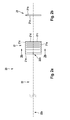
- Fig. 1a and 1b show an electrode member 10 according to a first embodiment with an electrode 11 and a lead 12 and a section through the electrode 11.
- the lead 12 consists of a rope of solid or stranded wire strands or - fibers of the type cited above.
- the distal end of the rope forms the electrode 11, in this embodiment, the wire along a central longitudinal axis 13 is helically wound or wound.
- the supply line 12 is in extension of this longitudinal axis 13 and may be either parallel to this or on this longitudinal axis.
- the electrode 11 is thus located immediately distal to the distal end 12b of the feed line 12.
- the electrode 11 further forms an outwardly (opposite to the longitudinal axis 13) facing electrically active electrode surface 11a, which is in an installed state with body medium and / or body tissue in contact. Due to the helical wound type, the rope forms gears 11b. As gear while a rotation of the wire around the longitudinal axis 13 around. At each additional turn another gear is formed.
- the aisles 11b are preferably adjacent directly following the distal or proximal preceding passage, but may also be designed differently, for example by a gap filled with insulating material between each gait 11b.
- the electrode surface 11 a is generally interrupted by a gap between each gear 11 b.
- FIGS Fig. 2a and 2b Another embodiment of the electrode element 20 is shown in FIGS Fig. 2a and 2b shown.
- the electrode 21 is not formed by helical winding or winding the rope, but by a meandering zig-zag forming consisting of rectilinear portions 21d, the opposite ends on the one hand with the distal preceding and on the other hand with the proximal subsequent rectilinear portion 21 d by opposite bent portions 21e are connected.
- a flat outwardly facing electrode surface 21a with two mutually perpendicular, imaginary outer edges 21c This arrangement also forms passageways 21b which extend through a rectilinear portion from a bent portion at one end to the bent portion at the other end of the rectilinear portion.
- the electrode 21 is in extension to the elongated lead 22 at its distal end 22b and is also formed by the distal end of the lead rope.
- this electrode element can be used, for example, in a so-called patch electrode line or else in an external sense electrode line which can be placed on the body.
- the planar, flat electrode 21 is tubular or cylindrical shaped along a longitudinal axis, wherein the elongate supply line 22 is located on or parallel to this longitudinal axis. This results in an easily manufactured configuration which can be used, for example, in an implantable electrode lead.
- individual, multiple or all gears 11b and 21b may be welded together, for example, by laser or resistance welding. This can be done, for example, alternately pairwise welding of gears 11b at circumferentially opposite locations, so as not to reduce the flexibility.
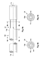
- Fig. 3 shows the portion of an implantable electrode lead 100 having an electrode element 10.
- the electrode element 10 is incorporated in an electrode lead body 110 so that the electrode 11 is isodiametric to the outer insulated surface 110a of the electrode lead body.
- the lead 12 extends to be electrically connected to a plug located and attached to the distal end of the electrode lead body.
- This plug corresponds to one of the standards IS-1, DF-1, IS-4, by means of which an electrical connection to an electrically active implant of the type mentioned above can be produced.
- the electrode lead body 110 is inserted into the Fig. 4a to 4c shown.
- the electrode lead body has at or near its distal, facing away from the plug End a recess 111 in the form of an annular groove, which has a radial depth which corresponds to the thickness of the rope and thus the electrode 11. That is, the diameter of the outward-facing electrically active surface 11a corresponds to the largest diameter of the electrode lead body 110 in its largest diameter position on the outer insulated surface, while the inner diameter of the electrode 11 corresponds to the outer diameter of the recess 111.
- first bore 112 In contact with the recess 111 is a first bore 112 with its distal end, wherein this bore extends parallel to the longitudinal axis 114 to the proximal end of the electrode line body 110.
- this bore 112 accommodates the feed line 12, which is led out of the bore of the electrode line body 110 into the recess 111 at its distal end 12b. Both the electrode 11 and the feed line 12 can be glued into the recess 111 or into the bore 112.
- an electrode lead body 110 additionally has a second bore 113, by means of which the implantable electrode lead 100 can be guided with the aid of a guide wire. This is usually on the longitudinal axis 114.
- the electrode may have the usual, known from the prior art active and passive fasteners.
- this can be multi-pole, that is to say designed with two or more electrodes.
- this for example, in a three-pole electrode line of the electrode line body 210 in the Fig. 5a to 5d have shown construction. He then points three in Fig. 4a to 4c described combinations of recesses 211a, 211b and 211 c, which are associated with each of these recesses in conjunction holes 212a, 212b and 212c. Each of these bores extends from a distal end located in or on the associated recesses along the longitudinal axis 214 of the electrode lead body 210 to the proximal end of the electrode lead body to which a known plug for electrical connection to an implant is attached.
- the bores 212a, 212b, and 212c are of different lengths. So that given necessary insulation with respect to the other leads 12, the holes are as in fig. 5b to 5d shown in the circumferential direction around the longitudinal axis 214 or around the bore 213 around advantageously distributed regularly. With this structure, implantable electrode leads with even more electrodes are possible.
Abstract
Description
Der Gegenstand der Patentanmeldung betrifft Verfahren zur Herstellung einer Elektrodenleitung, welches ein elektrisch aktives Elektrodenelement mit einer Elektrode mit einer nach außen weisenden elektrisch aktiven Elektrodenfläche und einer lang gestreckte elektrische Zuleitung umfasst, wobei das Elektrodenelement an seinem proximalen Ende eine elektrische Verbindung zu einem elektrisch aktiven Implantat herstellen kann und welche durchgehend als elektrisch leitendes Seil ausgebildet ist.The subject of the patent application relates to methods for producing an electrode lead comprising an electrically active electrode element with an electrode with an outwardly facing electrically active electrode surface and an elongate electrical lead, the electrode element at its proximal end an electrical connection to an electrically active implant can produce and which is continuously formed as an electrically conductive rope.
Solche Elektrodenelemente im weitestgehenden Sinne sind bereits aus dem Stand der Technik bekannt. So offenbart bereits die
Aus der genannten Schrift ist bekannt, diese Zuleitung aus einem Seil zu fertigen. Ein Seil im Sinne der Erfindung ist ein aus zusammengedrehten Einzeldrähten bestehendes längliches, flexibles und elastisches Element, in diesem Fall zur Übertragung von Energie. Das Seil wird aus einer oder mehreren Litzen (typischerweise 1, 3, 7 oder 12 Litzen) mittels "Verseilen" gefertigt, die in einem separaten Fertigungsschritt aus Einzeldrähten (typischerweise 3, 7, 19 Einzeldrähte) mittels "Verlitzen" hergestellt werden. Die Einzeldrähte können dabei aus Vollmaterial oder aus so genannten Mantel- oder DFT-Drähten (DFT = Drawn Filled Tube) bestehen, wobei Letztere Drähte mit einem Kernmaterial und einem vom Kernmaterial verschiedenen Mantelmaterial ist. Als Materialien für den Volldraht und das Kernmaterial eignen sich bevorzugt biokompatible und biostabile Metalle wie beispielsweise Platin-Iridium Legierungen, Tantal, Niob, Zirkonium und Molybdän einschließlich deren Legierungen. Zusätzlich eignen sich bei Manteldrähten generell besonders für das Mantelmaterial Platin-Iridium-Legierungen und für das Kernmaterial Kobalt-Chrom-Basislegierungen wie beispielsweise MP35N.
Bezüglich des Manteldrahtes betragen die Verhältniszahlen der Querschnittsflächen von Kern zu Mantel 25 - 95%.From the cited document is known to manufacture this lead from a rope. A rope in the context of the invention is an elongated, flexible and elastic element consisting of twisted individual wires, in this case for the transmission of energy. The rope is made of one or more strands (typically 1, 3, 7 or 12 strands) by means of "stranding", which are produced in a separate manufacturing step from single wires (typically 3, 7, 19 strands) by "stranding". The individual wires can be made of solid material or of so-called sheath or DFT wires (DFT = Drawn Filled Tube), the latter being wires with a core material and a sheath material other than the core material. As materials for the solid wire and the core material are preferably biocompatible and biostable metals such as platinum-iridium alloys, tantalum, niobium, zirconium and molybdenum including their alloys. In addition, in the case of jacket wires, platinum-iridium alloys are generally suitable, in particular for the jacket material, and cobalt-chromium base alloys, for example MP35N, for the core material.
With regard to the sheathed wire, the ratios of the cross-sectional areas from core to sheath are 25-95%.
Eine Elektrode im Sinne der Erfindung ist ein elektrisch aktives Element, welches geeignet ist, elektrische Energie oder elektrische Impulse (wie Stimulationsimpulse oder Defibrillationsschocks) abzugeben oder aber um Signale aus der Umgebung der Elektrode aufzunehmen und weiterzuleiten. Solche Stimulations- und Wahrnehmungselektroden bestehen im Stand der Technik wie der
Damit eine Elektrode Energie oder Impulse abgeben kann oder Körpersignale wie beispielsweise Temperatur, Impedanz, Herz- oder Hirnsignale aufnehmen kann, weist sie eine nach außen - also in Richtung der Umgebung der Elektrode - weisende elektrisch aktive Fläche auf, welche im Einbauzustand in eine Elektrodenleitung gegenüber der Umgebung unisoliert ist.So that an electrode can deliver energy or impulses or can absorb body signals such as temperature, impedance, heart or brain signals, it has an outwardly - ie in the direction of the environment of the electrode - facing electrically active surface, which in the installed state in an electrode line opposite the environment is uninsulated.
Das beschriebene Elektrodenelement aus dem Stand der Technik hat jedoch den besonderen Nachteil, dass die Zuleitung bzw. der Übergang zwischen Zuleitung und Elektrode eine erhöhte Bruchanfälligkeit aufweist. Am Implantationsort einer mit einem Elektrodenelement bestückten Elektrodenleitung wirken hohe und immerwährende Biegebelastungen, die durch Körperbewegung oder Herzschlag oder aber unterschiedliche Herzdrücke entstehen. Bei solchen Biegebelastungen ist der Übergang von einer flexiblen Zuleitung zu der starren Elektrode von besonderem Nachteil, da sich an dieser Übergangsstelle bei Biegebelastungen hohe Kräfte bilden. Durch die starren, fast schön spröden gefügten Übergangsstellen entsteht bei solchen Elektrodenelementen aus dem Stand der Technik ein Zuverlässigkeitsproblem, was sich an diesen Stellen in Brüchen und Wackelkontakten widerspiegelt. Solche Defekte sind für den Patienten lebensbedrohend und nicht reparabel. Folge ist der Austausch der kompletten Elektrodenleitung, welcher ebenfalls sehr riskant ist.
Des Weiteren weisen namentlich Crimp-Verbindungen zwischen Zuleitung und Elektrode eines Elektrodenlementes aus dem Stand der Technik zur sicheren Verbindung als Gegenlager notwendige zusätzliche Verbindungshülsen bzw. -stifte auf. Dadurch wird eine Durchmesservergrößerung bewirkt, was sich insofern nachteilig auswirkt, dass der Blutfluss von intravaskulär implantierbaren Elektroden gestört wird beziehungsweise ein Einsatz in einem Herzkranzgefäß zur Stimulation der linken Herzhälfte nicht mehr möglich ist.However, the described prior art electrode element has the particular disadvantage that the lead or the transition between the lead and electrode has an increased susceptibility to breakage. At the implantation site of an electrode lead equipped with an electrode element, high and constant bending loads occur, which arise as a result of body movement or heartbeat or else different cardiac pressures. In such bending loads, the transition from a flexible lead to the rigid electrode of particular disadvantage, since form at this transition point at bending loads high forces. Due to the rigid, almost brittle joined transition points arises in such electrode elements of the prior art, a reliability problem, which is reflected in these places in fractures and loose contacts. Such defects are life threatening to the patient and are not repairable. The result is the replacement of the complete electrode line, which is also very risky.
Furthermore, in particular crimp connections between the feed line and the electrode of an electrode element from the prior art for secure connection as an abutment necessary additional connecting sleeves or pins. This causes an increase in diameter, which is disadvantageous in that the blood flow is disturbed by intravascularly implantable electrodes or an insert in a coronary vessel for stimulation of the left half of the heart is no longer possible.
Ein elektrisch medizinisches Gerät kann sowohl ein externes Gerät wie ein externe Defibrillator oder andere Geräte zum Stimulieren eines menschlichen oder tierischen Körpers oder zum diagnostischen Messen von Körpersignalen sein. Besonders bevorzugt sind elektrisch aktive Implantate wie Herzschrittmacher, Kardioverter/Defibrillatoren oder Nervenstimulatoren. Auch sind andere Implantate umfasst, welche beispielsweise nur dazu dienen, intrakorporal Signale zu sammeln und an einen außerhalb des Körpers befindlichen Empfänger zu senden. Ebenfalls können Implantate umfasst sein, die mithilfe von Elektrodenleitungen elektrische Signale aufnehmen, aber keine elektrotherapeutische Stimulation erzeugen, beispielsweise durch Medikamentenabgabe.An electrical medical device may be both an external device such as an external defibrillator or other device for stimulating a human or animal body or for diagnosing body signals. Particularly preferred are electrically active implants such as pacemakers, cardioverter / defibrillators or nerve stimulators. Also, other implants are included, which are used, for example, only to collect intracorporeal signals and send to a receiver located outside the body. Also included may be implants that receive electrical signals via electrode leads but do not produce electrotherapeutic stimulation, such as drug delivery.
Das genannteElektrodenelement und die Elektrodenleitung zeichnen sich durch eine hervorragende Bruchsicherheit aus, da ein Materialstrang durchgehend die Zuleitung und die Elektrode bildet. Es entsteht also keine für Brüche unter Wechselbelastung anfällige Füge- oder Verbindungsstelle und auch kein Übergang von einem flexiblen zu einem starren Abschnitt.The said electrode element and the electrode line are characterized by excellent resistance to fracture, since a strand of material continuously forms the feed line and the electrode. Thus, there is no susceptible to breakage under alternating load joint or junction and no transition from a flexible to a rigid section.
Weiterhin zeichnet sich das genannte Elektrodenelement dadurch aus, dass erstmals eine komplett flexible Elektrode für geringe Durchmesser und kleine Stimulationsflächen vorgesehen werden können.Furthermore, said electrode element is characterized by the fact that for the first time a completely flexible electrode for small diameters and small stimulation surfaces can be provided.
Zudem hat sich vorteilhafterweise herausgestellt, dass Elektrodenelemente, bei denen die lang gestreckte Zuleitung und die Elektrode aus einem Materialstrang bestehen, eine hohe Spannungsfestigkeit aufweisen, wodurch ein flexibler Einsatz sowohl bei Defibrillationselektroden als auch Stimulationselektroden vorgesehen werden kann.In addition, it has advantageously been found that electrode elements in which the elongate lead and the electrode are made of a strand of material, have a high dielectric strength, whereby a flexible use can be provided both defibrillation electrodes and stimulation electrodes.
Das distale Ende des Zuleitungsseiles kann rohr- oder zylinderartig geformt sein und bildet so die Elektrode mit der nach außen weisenden elektrisch aktiven Elektrodenfläche, wobei vorzugsweise die Längsachse der rohr- oder zylinderartig geformten Elektrode in Verlängerung zur lang gestreckten Zuleitung liegt.The distal end of the supply cable can be tubular or cylindrical shaped and thus forms the electrode with the outwardly facing electrically active electrode surface, wherein preferably the longitudinal axis of the tubular or cylinder-shaped electrode is in extension to the elongate supply line.
Bevorzugt ist die rohrförmige Elektrode helixförmig ausgebildet, indem das Seil um die Längsachse herum aufgewickelt oder aufgespult ist.Preferably, the tubular electrode is formed helical, by the cable is wound or wound around the longitudinal axis.
Gemäß einer weiteren Alternative des Elektrodenelements ist das distale Ende des Zuleitungsseiles mäanderförmig geformt und die Elektrode als eine ebene Fläche mit zwei rechtwinklig zueinander liegenden gedachten Außenkanten ausgestaltet, wodurch die nach außen weisende elektrisch aktive Elektrodenfläche gebildet ist. Die Elektrode liegt dabei vorzugsweise in Verlängerung der Zuleitung, wobei besonders bevorzugt die flache Elektrode rohr- oder zylinderartig geformt ist.According to a further alternative of the electrode element, the distal end of the feed cable is formed meander-shaped and the electrode designed as a flat surface with two mutually perpendicular imaginary outer edges, whereby the outwardly facing electrically active electrode surface is formed. The electrode is preferably in extension of the supply line, wherein particularly preferably the flat electrode is tubular or cylindrical shaped.
Beide Alternativen zeugen von der flexiblen Einsetzbarkeit solcher Elektrodenelemente. Zum einen können sie als implantierbare Elektrodenleitung intrakardial, epikardial, im Koronarsinus oder zur Stimulation von Nerven eingesetzt werden. Diese weisen über ihre komplette Länge einen runden Querschnitt auf. Zum anderen können die Elektrodenelemente auch in Patch-Elektrodenleitungen eingesetzt werden, welche eine besondere Ausgestaltung von epikardialen Elektrodenleitungen sind und welche eine großflächige Stimulation außerhalb des Herzens erlauben. Denkbar sind auch externe Anwendungen, beispielsweise als externe Defibrillationselektrodenleitungen oder aber Elektrodenleitungen, mit denen nicht invasiv Körpersignale gemessen werden können.Both alternatives testify to the flexible applicability of such electrode elements. First, they can be used as an implantable lead intracardiac, epicardial, in the coronary sinus or for the stimulation of nerves. These have a round cross section over their entire length. On the other hand, the electrode elements also be used in patch electrode leads, which are a special embodiment of epicardial electrode leads and which allow large-area stimulation outside the heart. Also conceivable are external applications, for example as external defibrillation electrode lines or electrode lines with which non-invasive body signals can be measured.
Bei beiden Alternativen bildet das Seil im Bereich der Elektrode eine Vielzahl helixförmiger oder nebeneinander liegender Gänge, welche vorzugsweise zumindest abschnittsweise verschweißt sind.In both alternatives, the cable in the region of the electrode forms a plurality of helical or adjacent gears, which are preferably welded at least in sections.
Durch diese Anordnung wird der elektrische Widerstand verringert, was auch weiter zu einer weiteren Erhöhung der Spannungsfestigkeit und Zuverlässigkeit führt.By this arrangement, the electrical resistance is reduced, which further leads to a further increase in the dielectric strength and reliability.
Das Seil des Elektrodenelements ist aus Manteldrähten und/oder Drähten aus Vollmaterial gebildet, wobei der Kerndraht jedes einzelnen Manteldrahtes oder des einzelnen Drahtes aus Vollmaterial aus einem der Materialien ausgewählt aus Molybdän, Tantal, Niob, Zirkonium oder einer Platin-Iridium-Legierung besteht.The rope of the electrode element is formed of cladding wires and / or wires of solid material, wherein the core wire of each cladding wire or of the single wire of solid material consists of one of the materials selected from molybdenum, tantalum, niobium, zirconium or a platinum-iridium alloy.
Die implantierbare Elektrodenleitung umfasst einen Elektrodenleitungskörper mit einem proximalen und einem distalen Ende, einen am proximalen Ende des Elektrodenleitungskörpers befindlichen Stecker zur festen elektrischen Kontaktierung mit einem elektrisch aktiven Implantat, und mindestens ein soeben genanntes Elektrodenelement.The implantable electrode lead comprises an electrode lead body having a proximal and a distal end, a plug located at the proximal end of the electrode lead body for fixed electrical contact with an electrically active implant, and at least one just-mentioned electrode element.
Dadurch wird eine flexible und möglichst dünne Elektrodenleitung geschaffen, welche zuverlässig, bruchsicher und einfach herzustellen ist.As a result, a flexible and thin as possible electrode line is created, which is reliable, unbreakable and easy to manufacture.
Durch den Einsatz des Elektrodenelements erhält die Elektrodenleitung dieselben positiven Eigenschaften wie hohe Bruchsicherheit, geringe Durchmesser des Elektrodenleitungskörpers und hohe Spannungsfestigkeit.The use of the electrode element gives the electrode line the same positive properties as high resistance to breakage, small diameter of the electrode line body and high dielectric strength.
Das proximale Ende der Zuleitung des Elektrodenelements ist am proximalen Ende des Elektrodenleitungskörpers mit dem Stecker elektrisch leitend verbunden, wobei die Elektrode am distalen Ende und/oder im distalen Endbereich des Elektrodenleitungskörpers liegt.The proximal end of the lead of the electrode element is electrically conductively connected to the plug at the proximal end of the electrode lead body, wherein the electrode at the distal end and / or in the distal end region of the electrode lead body.
Der distale Endbereich ist der Bereich, der sich an der Stelle im oder am Körper, Körpermedium und/oder Körpergewebe befindet, an dem Signale aufgenommen werden sollen und/oder an dem der Körper stimuliert werden soll.The distal end region is the region that is at or in the body, body medium and / or body tissue where signals are to be acquired and / or the body is to be stimulated.
Weiterhin weist der Elektrodenleitungskörper am distalen Ende oder im distalen Bereich mindestens eine Aussparung, vorzugsweise eine Ringnut oder Quernut auf, in der die Elektrode form- und lagestabil liegt, wobei die nach außen weisende elektrisch aktive Elektrodenfläche so in den Elektrodenleitungskörper eingepasst ist, dass diese mit der nach äußeren isolierten Oberfläche isodiametrisch oder isoplanar ist.Furthermore, the electrode line body at the distal end or in the distal region at least one recess, preferably an annular groove or transverse groove in which the electrode is dimensionally stable and positionally stable, wherein the outwardly facing electrically active electrode surface is fitted into the electrode line body, that this with the outer insulated surface is isodiametric or isoplanar.
Durch diese Anordnung ist es möglich, eine Elektrodenleitung herzustellen, welche keine Absätze oder hervorstehenden, bei der Implantation und im Körper störenden Teile aufweist. Eine sichere und zielgerichtete Positionierung und ein sicherer Betrieb wird dadurch gewährleistet.By this arrangement, it is possible to produce an electrode line which has no paragraphs or protruding, disturbing during implantation and in the body parts. A secure and targeted positioning and safe operation is ensured.
Auch kann die Zuleitung des Elektrodenelements innerhalb des Elektrodenleitungskörpers isoliert verlaufen und im Bereich seines distalen Endes aus dem Elektrodenleitungskörper herausgeführt werden, damit die Elektrode, vorzugsweise die nach außen weisende elektrisch aktive Elektrodenfläche, unisoliert Kontakt zu Körpermedium und/oder Körpergewebe hat.Also, the lead of the electrode element within the electrode lead body can be insulated and led out in the region of its distal end from the electrode body, so that the electrode, preferably the outwardly facing electrically active electrode surface, uninsulated contact with body medium and / or body tissue.
Weiterhin kann in allen Ausführungsformen der Elektrodenleitung der Elektrodenleitungskörper flexibel und biegbar sein und vorzugsweise aus einem Kunststoff wie Silikon oder Polyurethan bestehen. Zusätzlich weist der Elektrodenleitungskörper der Elektrodenleitung mindestens eine erste Bohrung zur Aufnahme der Zuleitung und eine zweite Bohrung zur vorübergehenden Aufnahme eines Führungsdrahtes auf, wobei die erste Bohrung ein proximales Ende am oder im proximalen Ende des Elektrodenleitungskörpers und ein distales Ende in oder an einer ihr zugeordneten Aussparung aufweist.Furthermore, in all embodiments of the electrode line of the electrode line body may be flexible and bendable and preferably made of a plastic such as silicone or polyurethane. In addition, the electrode lead body of the electrode lead has at least a first bore for receiving the lead and a second bore for temporarily receiving a guide wire, wherein the first bore has a proximal end at or in the proximal end of the electrode lead body and a distal end in or at an associated recess having.
Durch diese innovative Anordnung wird die Herstellung der Elektrodenleitung erleichtert. Die Herstellung mit wenigen Schritten ermöglicht eine hochautomatisierte und ökonomische Herstellung von sämtlichen implantierbaren Elektrodenleitungen. Weiterhin wird eine angepasste und flexible Produktion von verschiedenartigen implantierbaren Elektroden ermöglicht.This innovative arrangement facilitates the production of the electrode line. The production in a few steps enables a highly automated and economical production of all implantable electrode leads. Furthermore, an adapted and flexible production of various implantable electrodes is made possible.
Der Patentanmeldung liegt die Aufgabe zugrunde, ein ökonomisches, flexibles und leichtes Herstellverfahren für solche Elektrodenleitungen mit dem genannten Elektrodenelement zu schaffen.The patent application is based on the object to provide an economical, flexible and easy manufacturing method for such electrode lines with said electrode element.
Diese Aufgabe wird durch den Gegenstand des Anspruchs 1 gelöst, indem das Herstellverfahren für das Elektrodenelement und die implantierbare Elektrodenleitung die folgenden Schritte umfasst:
- Herstellen des Elektrodenelements durch Formen der Elektrode aus dem Seil der Zuleitung
- Formen des Elektrodenleitungskörpers
- Montieren des Steckers und des Elektrodenelementes an den Elektrodenleitungskörper.
- Producing the electrode element by shaping the electrode from the cable of the supply line
- Shapes of the electrode lead body
- Mounting the plug and the electrode element to the electrode lead body.
Vorzugsweise umfasst der Formungsschritt der Herstellung des Elektrodenelements das Wickeln oder Spulen oder mäanderförmiges Formen des distalen Endes des Seiles.Preferably, the step of forming the electrode member comprises winding or winding or meandering the distal end of the cord.
Weiter bevorzugt umfasst der Schritt zur Formung des Elektrodenleitungskörpers ein Spritzgussverfahren, wobei Aussparung und die erste und zweite Bohrung geformt werden.More preferably, the step of forming the electrode lead body comprises an injection molding process wherein recess and the first and second bores are formed.
Besonders bevorzugt umfasst der Montageschritt zusätzlich die folgenden Schritte:
- Einfädeln des proximalen Endes der Zuleitung in die erste Bohrung in oder an der zugeordneten Aussparung und Schieben der Zuleitung in Richtung des proximalen Endes des Elektrodenleitungskörpers, bis die Elektrode in der zugeordneten Aussparung zu liegen kommt,
- Kleben der Elektrode an den Elektrodenleitungskörper in der Aussparung,
- elektrisches Verbinden des proximalen Endes der Zuleitung mit dem Stecker und Befestigen des Steckers am Elektrodenleitungskörper.
- Threading the proximal end of the lead into the first bore in or at the associated recess and sliding the lead toward the proximal end of the electrode lead body until the electrode comes to lie in the associated recess,
- Bonding the electrode to the electrode lead body in the recess,
- electrically connecting the proximal end of the lead to the plug and attaching the plug to the electrode lead body.
Weitere Ausführungsmöglichkeiten sind in der Beschreibung oder den Zeichnungen aufgeführt.Other possible embodiments are listed in the description or the drawings.
Anhand der Figuren wird im Folgenden die Erfindung beschrieben. Es zeigen:
- Fig. 1a
- eine Ausführungsform des Elektrodenelements
- Fig. 1b
- eine Schnittdarstellung durch die Elektrode des Elektrodenelements aus
Fig. 1a entlang der der Schnittlinie 1b - Fig. 2a
- eine weitere Ausführungsform des Elektrodenelements
- Fig. 2b
- eine Schnittdarstellung durch die Elektrode des Elektrodenelements aus
Fig. 2a entlang der Schnittlinie 2b - Fig. 3
- eine implantierbare Elektrodenleitung mit einem Elektrodenelement
- Fig. 4a
- einen Elektrodenleitungskörper für eine Elektrodenleitung mit einem Elektrodenelement
- Fig. 4b
- eine Schnittdarstellung durch die Aussparung des Elektrodenlei- tungskörpers entlang der Schnittlinie 4b
- Fig. 4c
- eine Schnittdarstellung durch den Elektrodenleitungskörper entlang der
Schnittlinie 4c - Fig. 5a
- einen Elektrodenleitungskörper für eine mehrpolige implantierbare Elektrodenleitung
- Fig. 5b bis Fig. 5d
- Schnittdarstellungen des Elektrodenleitungskörpers für mehrpolige implantierbare Elektrodenleitungen entlang der Schnittlinien
5b bis 5d
- Fig. 1a
- an embodiment of the electrode element
- Fig. 1b
- a sectional view through the electrode of the electrode element
Fig. 1a along thesection line 1b - Fig. 2a
- a further embodiment of the electrode element
- Fig. 2b
- a sectional view through the electrode of the electrode element
Fig. 2a along thesection line 2b - Fig. 3
- an implantable electrode lead with an electrode element
- Fig. 4a
- an electrode lead body for an electrode lead having an electrode member
- Fig. 4b
- a sectional view through the recess of the Elektrodenleit- body along the
section line 4b - Fig. 4c
- a sectional view through the electrode line body along the
section line 4c - Fig. 5a
- an electrode lead body for a multipolar implantable electrode lead
- Fig. 5b to Fig. 5d
- Sectional views of the electrode lead body for multipolar implantable electrode leads along the
section lines 5b to 5d
Die Elektrode 11 bildet weiterhin eine nach außen (von der Längsachse 13 entgegengesetzt) weisende elektrisch aktive Elektrodenfläche 11a, welche in einem eingebauten Zustand mit Körpermedium und/oder Körpergewebe in Kontakt steht. Durch die helixförmig aufgewickelte Art bildet das Seil Gänge 11b. Als Gang gilt dabei eine Umdrehung des Drahtes um die Längsachse 13 herum. Bei jeder weiteren Umdrehung wird ein weiterer Gang gebildet. Die Gänge 11b sind bevorzugt direkt distal folgenden oder proximal vorhergehenden Gang anliegend, können aber auch andersartig ausgebildet sein, beispielsweise indem ein mit Isolationsmaterial aufgefüllter Zwischenraum zwischen jedem Gang 11b besteht. Somit wird die Elektrodenoberfläche 11 a generell von einem Zwischenraum zwischen jedem Gang 11b unterbrochen.
The
Eine weitere Ausführungsform des Elektrodenelements 20 ist in den
Die Elektrode 21 befindet sich in Verlängerung zur lang gestreckten Zuleitung 22 an dessen distalem Ende 22b und wird ebenfalls durch das distale Ende des Zuleitungsseils gebildet.The
In der genannten Konfiguration kann dieses Elektrodenelement beispielsweise Einsatz in einer so genannten Patch-Elektrodenleitung oder aber in einer externen, auf den Körper auflegbaren Wahrnehmungselektrodenleitung eingesetzt werden. Bevorzugt ist die ebene, flache Elektrode 21 jedoch rohr- oder zylinderförmig entlang einer Längsachse geformt, wobei die lang gestreckte Zuleitung 22 auf oder parallel dieser Längsachse liegt. So entsteht eine einfach herstellbare Konfiguration, welche beispielsweise in einer implantierbaren Elektrodenleitung eingesetzt werden kann.In the configuration mentioned, this electrode element can be used, for example, in a so-called patch electrode line or else in an external sense electrode line which can be placed on the body. Preferably, however, the planar,
Bei beiden Ausführungen können einzelne, mehrere oder alle Gänge 11b und 21b beispielsweise durch Laser- oder Widerstandsschweißen miteinander verschweißt sein. Dies kann beispielsweise ein abwechselnd paarweises Verschweißen von Gängen 11b an im Umfangsrichtung entgegengesetzten Stellen erfolgen, um die Flexibilität nicht zu vermindern.In both embodiments, individual, multiple or all
Im Detail wird der Elektrodenleitungskörper 110 in den
Mit der Aussparung 111 in Kontakt steht eine erste Bohrung 112 mit ihrem distalen Ende, wobei diese Bohrung parallel zur Längsachse 114 bis zum proximalen Ende des Elektrodenleitungskörpers 110 verläuft. Diese Bohrung 112 nimmt im zusammengesetzten Zustand der implantierbaren Elektrodenleitung 100 die Zuleitung 12 auf, welche an deren distalen Ende 12b aus der Bohrung des Elektrodenleitungskörpers 110 in die Aussparung 111 herausgeführt ist. Sowohl die Elektrode 11 als auch die Zuleitung 12 können in die Aussparung 111 bzw. in die Bohrung 112 eingeklebt sein.In contact with the
Des Weiteren kann ein solcher Elektrodenleitungskörper 110 zusätzlich eine zweite Bohrung 113 aufweisen, anhand derer die implantierbare Elektrodenleitung 100 mit Hilfe eines Führungsdrahtes geführt werden kann. Diese liegt üblicherweise auf der Längsachse 114. Zusätzlich kann die Elektrode die üblichen, aus dem Stand der Technik bekannten aktiven und passiven Befestigungen aufweisen.In addition, such an
In einer weiteren Ausgestaltung der implantierbaren Elektrodenleitung kann diese mehrpolig, das heißt mit zwei oder mehreren Elektroden ausgeführt sein. Dazu kann beispielsweise bei einer drei-poligen Elektrodenleitung der Elektrodenleitungskörper 210 den in
Claims (4)
wobei das Elektrodenelement eine Elektrode (11, 12) mit einer nach außen weisenden elektrisch aktiven Elektrodenfläche (11a, 21a), und eine lang gestreckte elektrische Zuleitung (12, 22), welche an seinem proximalen Ende (12a, 22a) eine elektrische Verbindung zu einem elektrisch aktiven medizinischen Gerät herstellen kann und welche durchgehend als elektrisch leitendes Seil ausgebildet ist und bei der das Seil an seinem distalen Ende die Elektrode bildet;
und wobei Elektrodenleitung (100) neben dem Elektrodenelement (10, 20) einen Elektrodenleitungskörper (110) mit einem proximalen und einem distalen Ende und einen am proximalen Ende des Elektrodenleitungskörpers befindlichen Stecker zur festen elektrischen Kontaktierung mit einem elektrisch aktiven Implantat, umfasst; wobei das Verfahren folgende Schritte umfasst:
wherein the electrode element comprises an electrode (11, 12) with an outwardly facing electrically active electrode surface (11a, 21a), and an elongated electrical supply line (12, 22) which at its proximal end (12a, 22a) an electrical connection to an electrically active medical device and which is continuously formed as an electrically conductive cable and in which the cable forms the electrode at its distal end;
and wherein electrode lead (100) adjacent to the electrode member (10, 20) comprises an electrode lead body (110) having proximal and distal ends and a plug located at the proximal end of the electrode lead body for fixed electrical contact with an electrically active implant; the method comprising the steps of:
Applications Claiming Priority (1)
| Application Number | Priority Date | Filing Date | Title |
|---|---|---|---|
| DE102009002707A DE102009002707A1 (en) | 2009-04-29 | 2009-04-29 | Electrode element, electrode line with an electrode element and manufacturing method of an electrode line |
Publications (1)
| Publication Number | Publication Date |
|---|---|
| EP2246092A1 true EP2246092A1 (en) | 2010-11-03 |
Family
ID=42126058
Family Applications (1)
| Application Number | Title | Priority Date | Filing Date |
|---|---|---|---|
| EP10157044A Withdrawn EP2246092A1 (en) | 2009-04-29 | 2010-03-19 | Method for manufacturing an electrode cable |
Country Status (3)
| Country | Link |
|---|---|
| US (1) | US20100280583A1 (en) |
| EP (1) | EP2246092A1 (en) |
| DE (1) | DE102009002707A1 (en) |
Cited By (1)
| Publication number | Priority date | Publication date | Assignee | Title |
|---|---|---|---|---|
| EP3292885A1 (en) * | 2016-09-06 | 2018-03-14 | BIOTRONIK SE & Co. KG | Stretchable electrode conductor assembly and medical implant |
Citations (6)
| Publication number | Priority date | Publication date | Assignee | Title |
|---|---|---|---|---|
| US3788329A (en) * | 1972-04-17 | 1974-01-29 | Medtronic Inc | Body implantable lead |
| DE3530269A1 (en) * | 1985-08-22 | 1987-02-26 | Biotronik Mess & Therapieg | Implantable electrode for cardiac stimulation |
| EP0408358A2 (en) * | 1989-07-14 | 1991-01-16 | Case Western Reserve University | Intramuscular electrode for neuromuscular stimulation system |
| DE19758368A1 (en) | 1997-12-29 | 1999-07-01 | Biotronik Mess & Therapieg | Defibrillation electrode assembly |
| WO2000056399A1 (en) * | 1999-03-23 | 2000-09-28 | Cardiac Pacemakers, Inc. | Adaptable electrode for coronary venous leads |
| US7174220B1 (en) | 2004-03-16 | 2007-02-06 | Pacesetter, Inc. | Construction of a medical electrical lead |
Family Cites Families (5)
| Publication number | Priority date | Publication date | Assignee | Title |
|---|---|---|---|---|
| US4860769A (en) * | 1987-11-12 | 1989-08-29 | Thomas J. Fogarty | Implantable defibrillation electrode |
| US5397342A (en) * | 1993-06-07 | 1995-03-14 | Cardiac Pacemakers, Inc. | Resilient structurally coupled and electrically independent electrodes |
| DE19930268A1 (en) * | 1999-06-25 | 2001-01-04 | Biotronik Mess & Therapieg | Flexible, rollable flat electrode for defibrillator, used with implantation catheter for introduction and release in pericardial cavity, has elasticity such that it is self-unrolling by elastic resilience |
| DE102004048991B4 (en) * | 2004-10-04 | 2010-01-28 | Biotronik Crm Patent Ag | electrode line |
| US7930038B2 (en) * | 2005-05-27 | 2011-04-19 | Cardiac Pacemakers, Inc. | Tubular lead electrodes and methods |
-
2009
- 2009-04-29 DE DE102009002707A patent/DE102009002707A1/en not_active Withdrawn
-
2010
- 2010-03-19 EP EP10157044A patent/EP2246092A1/en not_active Withdrawn
- 2010-04-23 US US12/766,097 patent/US20100280583A1/en not_active Abandoned
Patent Citations (7)
| Publication number | Priority date | Publication date | Assignee | Title |
|---|---|---|---|---|
| US3788329A (en) * | 1972-04-17 | 1974-01-29 | Medtronic Inc | Body implantable lead |
| DE3530269A1 (en) * | 1985-08-22 | 1987-02-26 | Biotronik Mess & Therapieg | Implantable electrode for cardiac stimulation |
| EP0408358A2 (en) * | 1989-07-14 | 1991-01-16 | Case Western Reserve University | Intramuscular electrode for neuromuscular stimulation system |
| DE19758368A1 (en) | 1997-12-29 | 1999-07-01 | Biotronik Mess & Therapieg | Defibrillation electrode assembly |
| EP0927561A2 (en) * | 1997-12-29 | 1999-07-07 | BIOTRONIK Mess- und Therapiegeräte GmbH & Co Ingenieurbüro Berlin | Defibrillation electrode device |
| WO2000056399A1 (en) * | 1999-03-23 | 2000-09-28 | Cardiac Pacemakers, Inc. | Adaptable electrode for coronary venous leads |
| US7174220B1 (en) | 2004-03-16 | 2007-02-06 | Pacesetter, Inc. | Construction of a medical electrical lead |
Cited By (1)
| Publication number | Priority date | Publication date | Assignee | Title |
|---|---|---|---|---|
| EP3292885A1 (en) * | 2016-09-06 | 2018-03-14 | BIOTRONIK SE & Co. KG | Stretchable electrode conductor assembly and medical implant |
Also Published As
| Publication number | Publication date |
|---|---|
| DE102009002707A1 (en) | 2010-11-04 |
| US20100280583A1 (en) | 2010-11-04 |
Similar Documents
| Publication | Publication Date | Title |
|---|---|---|
| DE60017716T2 (en) | COEXTRUDED MEDICAL MULTILUMENLINE | |
| DE69820418T2 (en) | COIL WIRE INSULATION FOR BIOMEDICAL LADDERS | |
| DE60111222T2 (en) | ELECTRICALLY INSULATED CABLE WITH MULTIPLE LADDERS | |
| EP2711046B1 (en) | Electrode wire and connector piece for electromedical implants | |
| DE602004005066T2 (en) | IMPLANTABLE MEDICAL AND MANUFACTURING PROCESS | |
| DE19957241B4 (en) | Electric cable for medical purposes and system for introducing same | |
| DE112010001330T5 (en) | MRI-compatible implantable connection electrode interface | |
| EP2110154B1 (en) | Device for reducing the interference susceptibility of elongate impants | |
| DE69820889T2 (en) | Management for medical purposes | |
| DE102009033767B4 (en) | Connection element for conduction coil | |
| EP1285678B1 (en) | Single electrode lead for pacemaker systems | |
| EP2604312B1 (en) | Conductive coil arrangement and electrode catheter arrangement, in particular for cardiac therapy | |
| DE102009033770B4 (en) | Connection between stimulation electrode and conduction coil | |
| CH656313A5 (en) | Electrode with an electrical conductor which is connected to a contact provided for forming a connection with tissue | |
| DE102009033769B4 (en) | Crimp connection between stimulation electrode and conduction coil | |
| EP1955729A2 (en) | Electrode wire and connector piece for an implantable heart stimulator | |
| EP2985053A1 (en) | Implantable electrical line | |
| EP2110156B1 (en) | Field decoupling element for use with an implantable lead and implantable medical device | |
| EP2246092A1 (en) | Method for manufacturing an electrode cable | |
| DE3304506A1 (en) | Electrode plug for a pacemaker electrode | |
| EP2478933A2 (en) | Implantable device | |
| EP3630266B1 (en) | Electromedical adapter, electromedical electrode and electromedical pulse generator | |
| EP2465569B1 (en) | Implantable device | |
| EP0306442B1 (en) | Implantation electrode for heart stimulation | |
| EP2918308A1 (en) | Insulation tube for an electrical lead for medical use, and method for producing such a tube |
Legal Events
| Date | Code | Title | Description |
|---|---|---|---|
| PUAI | Public reference made under article 153(3) epc to a published international application that has entered the european phase |
Free format text: ORIGINAL CODE: 0009012 |
|
| AK | Designated contracting states |
Kind code of ref document: A1 Designated state(s): AT BE BG CH CY CZ DE DK EE ES FI FR GB GR HR HU IE IS IT LI LT LU LV MC MK MT NL NO PL PT RO SE SI SK SM TR |
|
| AX | Request for extension of the european patent |
Extension state: AL BA ME RS |
|
| 17P | Request for examination filed |
Effective date: 20110502 |
|
| 17Q | First examination report despatched |
Effective date: 20170320 |
|
| STAA | Information on the status of an ep patent application or granted ep patent |
Free format text: STATUS: THE APPLICATION IS DEEMED TO BE WITHDRAWN |
|
| 18D | Application deemed to be withdrawn |
Effective date: 20171003 |