EP2248455A1 - Floor cleaning machine - Google Patents
Floor cleaning machine Download PDFInfo
- Publication number
- EP2248455A1 EP2248455A1 EP09006278A EP09006278A EP2248455A1 EP 2248455 A1 EP2248455 A1 EP 2248455A1 EP 09006278 A EP09006278 A EP 09006278A EP 09006278 A EP09006278 A EP 09006278A EP 2248455 A1 EP2248455 A1 EP 2248455A1
- Authority
- EP
- European Patent Office
- Prior art keywords
- cleaning machine
- floor cleaning
- elongated element
- machine according
- squeegee
- Prior art date
- Legal status (The legal status is an assumption and is not a legal conclusion. Google has not performed a legal analysis and makes no representation as to the accuracy of the status listed.)
- Granted
Links
Images


Classifications
-
- A—HUMAN NECESSITIES
- A47—FURNITURE; DOMESTIC ARTICLES OR APPLIANCES; COFFEE MILLS; SPICE MILLS; SUCTION CLEANERS IN GENERAL
- A47L—DOMESTIC WASHING OR CLEANING; SUCTION CLEANERS IN GENERAL
- A47L11/00—Machines for cleaning floors, carpets, furniture, walls, or wall coverings
- A47L11/29—Floor-scrubbing machines characterised by means for taking-up dirty liquid
- A47L11/30—Floor-scrubbing machines characterised by means for taking-up dirty liquid by suction
- A47L11/302—Floor-scrubbing machines characterised by means for taking-up dirty liquid by suction having rotary tools
- A47L11/305—Floor-scrubbing machines characterised by means for taking-up dirty liquid by suction having rotary tools the tools being disc brushes
-
- A—HUMAN NECESSITIES
- A47—FURNITURE; DOMESTIC ARTICLES OR APPLIANCES; COFFEE MILLS; SPICE MILLS; SUCTION CLEANERS IN GENERAL
- A47L—DOMESTIC WASHING OR CLEANING; SUCTION CLEANERS IN GENERAL
- A47L11/00—Machines for cleaning floors, carpets, furniture, walls, or wall coverings
- A47L11/40—Parts or details of machines not provided for in groups A47L11/02 - A47L11/38, or not restricted to one of these groups, e.g. handles, arrangements of switches, skirts, buffers, levers
- A47L11/4036—Parts or details of the surface treating tools
- A47L11/4044—Vacuuming or pick-up tools; Squeegees
-
- A—HUMAN NECESSITIES
- A47—FURNITURE; DOMESTIC ARTICLES OR APPLIANCES; COFFEE MILLS; SPICE MILLS; SUCTION CLEANERS IN GENERAL
- A47L—DOMESTIC WASHING OR CLEANING; SUCTION CLEANERS IN GENERAL
- A47L11/00—Machines for cleaning floors, carpets, furniture, walls, or wall coverings
- A47L11/40—Parts or details of machines not provided for in groups A47L11/02 - A47L11/38, or not restricted to one of these groups, e.g. handles, arrangements of switches, skirts, buffers, levers
- A47L11/4061—Steering means; Means for avoiding obstacles; Details related to the place where the driver is accommodated
-
- A—HUMAN NECESSITIES
- A47—FURNITURE; DOMESTIC ARTICLES OR APPLIANCES; COFFEE MILLS; SPICE MILLS; SUCTION CLEANERS IN GENERAL
- A47L—DOMESTIC WASHING OR CLEANING; SUCTION CLEANERS IN GENERAL
- A47L11/00—Machines for cleaning floors, carpets, furniture, walls, or wall coverings
- A47L11/40—Parts or details of machines not provided for in groups A47L11/02 - A47L11/38, or not restricted to one of these groups, e.g. handles, arrangements of switches, skirts, buffers, levers
- A47L11/4063—Driving means; Transmission means therefor
- A47L11/4069—Driving or transmission means for the cleaning tools
Definitions
- the present invention relates to a floor cleaning machine, preferably for industrial field.
- the present floor cleaning machine is of the type comprising a brush that is drivable via a substantially vertical shaft to rotate and a squeegee that is arranged to the rear of such a brush, opposite to the travel direction of the floor cleaning machine.
- a kind of flooring machine that can be moved by an operator or preferably provided with independent drive, comprises means for rotating the squeegee around the brush as a consequence of directional changes of the machine.
- the squeegee which is a strip or blade of elastic material such as, rubber or the like, collects the washing liquid and the dirt removed by the action of the brush, being provided with suction means to suction the dirt and the washing liquid in order to leave the floor clear and dry.
- the aim of the present invention therefore, is to provide a floor cleaning machine that can be quickly assembled and disassembled.
- Further object of the present invention is to provide a floor cleaning machine that is provided with rotating means that can be manufactured just in one piece and, at same time, provided with reduced inertial moment.
- the present floor cleaning machine that comprises at least one brush that is drivable via a substantially vertical shaft to rotate, at least one squeegee that is arranged to the rear of said at least one brush, opposite to the travel direction of said floor cleaning machine, and means for rotating said at least one squeegee, at least in part, around said at least one brush, characterized in that said rotating means comprise an elongated element that is provided with a first portion, rotatably freely coupled to said vertical shaft, and a second portion, coupled directly, or indirectly, to said at least one squeegee.
- said rotating means comprise an elongated element that is provided with a first portion, rotatably freely coupled to said vertical shaft, and a second portion, coupled directly, or indirectly, to said at least one squeegee.
- said elongated element is arranged horizontally and is substantially flat; besides said first portion is provided with a hole that is concentric to said vertical shaft so that the elongated element can be manufactured just in one piece. It should be remarked that substantially flat means that the thickness of said elongated element has dimensions negligible with respect to the other two spatial dimensions. Therefore said elongated element is similar to a thin and narrow plate that rotates around an axis perpendicular to the two base surfaces of the plate.
- said rotating means comprise a connecting element that is provided with a first end rotatably freely coupled around a first horizontal axis to the second portion of said elongated element, and a second end freely rotatably coupled about a second horizontal axis to said at least one squeegee.
- the squeegee can be moved up and down by the operator or automatically adjusts in case the floor is not perfectly smooth.
- both first and second embodiment of said floor cleaning machine comprise means for reducing the friction between said horizontal elongated element and said vertical shaft, at least during their relative rotation.
- Said friction reducing means are arranged into the inner portion of said hole and comprise a bushing or a ball bearing which are preferably formed in one piece with said hole.
- said friction reducing means comprise a plurality of spherical balls that roll on the external surface of said shaft, along a track for said plurality of balls.
- Each ball being is radially arranged into the inner portion of said hole and housed in a cavity of said inner portion.
- the first portion of said horizontal elongated element is substantially circular and the second portion of said horizontal elongated element is substantially rectangular, wherein the ratio of the transversal dimensions of the first portion of said horizontal elongated element to the transversal dimensions of the second portion of said elongated element is comprised between 1 and 5, preferably 4.
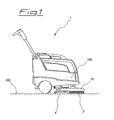
- the floor cleaning machine 1 comprises a chassis 100 that supports a brush 2 that is drivable by means of an electrical motor 200 via a substantially vertical shaft 3 to rotate, a squeegee 4 that is arranged to the rear of said brush 2, opposite to the travel direction of said floor cleaning machine 1, and means 5 for rotating said at least one squeegee 4, at least in part, around said a brush 2.
- the brush 2 is protected by an housing 70 that completely surrounds and in operation is integral with the brush during its rotation.
- the floor cleaning machine 1 can also comprise more than one brush without falling out from the scope of protection of the present invention.
- the above mentioned rotating means 5 comprise an elongated element 6 that is provided with a first portion 6a, rotatably freely coupled to said vertical shaft 3, and a second portion 6b, directly coupled to said squeegee.
- said elongated element 6 is arranged horizontal, i.e. parallel to the floor 300 to be cleaned, and it is substantially flat. Therefore said elongated element 6 is shaped as a plate, i.e. it is provided with a thickness that has dimensions negligible with respect to the other two dimensions, which rotates around an axis perpendicular to the two base surfaces 6e, 6f ( figure 6 ) of the elongated element 6.
- Such a configuration of the elongated element 6 is particularly advantageous as the inertial momentum is extremely low and the elongated element can be manufactured very quickly. Furthermore such a configuration allows the elongated element to be lightly and elastically bent in case the machine 1 slides on a floor 300 which is not perfectly smooth. In practise, the flattened shape of the elongated element, consequently its capacity of lightly bending, allows the squeegee to adapt to the different surfaces of the floor without any rotational coupling between the squeegee and the elongated element.
- first portion 6a of said elongated element 6 is provided with a hole 6c that is concentric to said vertical shaft 3. Said hole 6c can be obtained during the same operation for manufacturing the elongated element thus reducing costs and saving money.
- said rotating means 5 comprise a connecting element 9 that is provided with a first end 9a rotatably freely coupled around a first horizontal axis X to the second portion 6b of said elongated element 6, and a second end 9b freely rotatably coupled about a second horizontal axis Y to said at least one squeegee 4.
- Said connecting element 9 comprises two different rods 60, 61 that pivot about two hinges 30, 31 connected to the end 50 of the second portion 6b of said elongated element 6. In such a case said elongated element 6 is coupled indirectly to said squeegee 4.
- the second embodiment allows the squeegee 4 to be moved up and down during any working condition of the machine 1 or to automatically adjust in case the floor is not perfectly smooth.
- said machine 1 comprises means 10 for reducing the friction between said horizontal elongated element 6 and said vertical shaft 3, at least during their relative rotation.
- Said friction reducing means 10 are arranged into the inner portion 6d of said hole 6c and they can be chosen between a bushing or a ball bearing (both alternatives not shown), which can be separated from the hole 6 or formed in one piece with said hole 6.
- said friction reducing means 10 comprise a plurality 14 of spherical balls 14a that roll on the external surface 18 of said shaft 3.
- each ball 14a is radially arranged into the inner portion 6d of said hole 6c and housed in a cavity 16 of said inner portion 6d.
- said shaft 3 comprises a track 17 for said plurality 14 of balls.
- said first portion 6a of said elongated element 6 is substantially circular and the second portion 6b of said horizontal elongated element 6 is substantially rectangular.
- the applicant has advantageously found out that the ratio of the transversal dimensions D of the first portion 6a of said horizontal elongated element 6 to the transversal dimensions L of the second portion 6b of said elongated element has to be comprised between 1 and 5, preferably 4, in order to obtain the most efficient rotation of said rotating means 5 around the shaft 3.
Abstract
Description
- The present invention relates to a floor cleaning machine, preferably for industrial field. In particular the present floor cleaning machine is of the type comprising a brush that is drivable via a substantially vertical shaft to rotate and a squeegee that is arranged to the rear of such a brush, opposite to the travel direction of the floor cleaning machine. Furthermore such a kind of flooring machine, that can be moved by an operator or preferably provided with independent drive, comprises means for rotating the squeegee around the brush as a consequence of directional changes of the machine. Even more in detail the squeegee, which is a strip or blade of elastic material such as, rubber or the like, collects the washing liquid and the dirt removed by the action of the brush, being provided with suction means to suction the dirt and the washing liquid in order to leave the floor clear and dry.
- The solutions of prior art floor cleaning machines present the drawback that the shaft around that the squeegee pivots is different from the shaft around that the brush pivots, thus making very hard and time consuming both the assembly and disassembly of the machine in case of maintenance. Another drawback of the prior art floor cleaning machines is that the means for rotating the squeegee, albeit provided with a relative low inertial moment, are manufactured in more than one component welded or coupled each other to form said means for rotating the squeegee. Such a configuration of the rotating means increases the costs and the time for manufacturing the floor cleaning machine.
- The aim of the present invention therefore, is to provide a floor cleaning machine that can be quickly assembled and disassembled.
- Further object of the present invention is to provide a floor cleaning machine that is provided with rotating means that can be manufactured just in one piece and, at same time, provided with reduced inertial moment.
- These and other aims are achieved by the present floor cleaning machine that comprises at least one brush that is drivable via a substantially vertical shaft to rotate, at least one squeegee that is arranged to the rear of said at least one brush, opposite to the travel direction of said floor cleaning machine, and means for rotating said at least one squeegee, at least in part, around said at least one brush, characterized in that said rotating means comprise an elongated element that is provided with a first portion, rotatably freely coupled to said vertical shaft, and a second portion, coupled directly, or indirectly, to said at least one squeegee. In this way the assembly and disassembly of the machine is extremely quick since all components of the floor cleaning machine are mounted on the vertical shaft for rotating said brush and said squeegee.
- Furthermore said elongated element is arranged horizontally and is substantially flat; besides said first portion is provided with a hole that is concentric to said vertical shaft so that the elongated element can be manufactured just in one piece. It should be remarked that substantially flat means that the thickness of said elongated element has dimensions negligible with respect to the other two spatial dimensions. Therefore said elongated element is similar to a thin and narrow plate that rotates around an axis perpendicular to the two base surfaces of the plate.
- According to a second embodiment of the invention, said rotating means comprise a connecting element that is provided with a first end rotatably freely coupled around a first horizontal axis to the second portion of said elongated element, and a second end freely rotatably coupled about a second horizontal axis to said at least one squeegee. In such a way the squeegee can be moved up and down by the operator or automatically adjusts in case the floor is not perfectly smooth.
- Again both first and second embodiment of said floor cleaning machine comprise means for reducing the friction between said horizontal elongated element and said vertical shaft, at least during their relative rotation. Said friction reducing means are arranged into the inner portion of said hole and comprise a bushing or a ball bearing which are preferably formed in one piece with said hole.
- Alternatively, said friction reducing means comprise a plurality of spherical balls that roll on the external surface of said shaft, along a track for said plurality of balls. Each ball being is radially arranged into the inner portion of said hole and housed in a cavity of said inner portion.
- According to a preferable embodiment, the first portion of said horizontal elongated element is substantially circular and the second portion of said horizontal elongated element is substantially rectangular, wherein the ratio of the transversal dimensions of the first portion of said horizontal elongated element to the transversal dimensions of the second portion of said elongated element is comprised between 1 and 5, preferably 4.
- A description of certain embodiments of the present invention will now be provided purely as a non-limiting example, with reference to the appended drawings, wherein:
-
figure 1 shows a perspective view of the floor cleaning machine; -
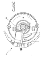
figure 2 shows a top view of the floor cleaning machine according tofigure 1 , wherein only the inferior part of the floor cleaning machine is visible; -
figure 3 shows a top perspective view of the friction reducing means of the machine according tofigure 2 ; -
figure 4a shows a top view of the machine according tofigure 2 , wherein the squeegee is placed in a first angular position with respect to the brush; -
figure 4b shows a top view of the machine according tofigure 2 , wherein the squeegee is placed in a second angular position with respect to the brush; -
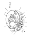
figure 5 shows a perspective view of the floor cleaning machine according to a second embodiment of the invention, wherein only the inferior part of the floor cleaning machine is visible; -
figure 6 shows a perspective view of the elongated element. - In all figures, the floor cleaning machine according to the invention is identified throughout by the numeral 1.
- The floor cleaning machine 1 comprises a
chassis 100 that supports abrush 2 that is drivable by means of anelectrical motor 200 via a substantiallyvertical shaft 3 to rotate, asqueegee 4 that is arranged to the rear of saidbrush 2, opposite to the travel direction of said floor cleaning machine 1, and means 5 for rotating said at least onesqueegee 4, at least in part, around said abrush 2. Thebrush 2 is protected by anhousing 70 that completely surrounds and in operation is integral with the brush during its rotation. - It should be noted that the floor cleaning machine 1 can also comprise more than one brush without falling out from the scope of protection of the present invention.
- The above mentioned
rotating means 5 comprise anelongated element 6 that is provided with afirst portion 6a, rotatably freely coupled to saidvertical shaft 3, and asecond portion 6b, directly coupled to said squeegee. - As shown in
figure 1 , saidelongated element 6 is arranged horizontal, i.e. parallel to thefloor 300 to be cleaned, and it is substantially flat. Therefore saidelongated element 6 is shaped as a plate, i.e. it is provided with a thickness that has dimensions negligible with respect to the other two dimensions, which rotates around an axis perpendicular to the twobase surfaces figure 6 ) of theelongated element 6. - Such a configuration of the
elongated element 6 is particularly advantageous as the inertial momentum is extremely low and the elongated element can be manufactured very quickly. Furthermore such a configuration allows the elongated element to be lightly and elastically bent in case the machine 1 slides on afloor 300 which is not perfectly smooth. In practise, the flattened shape of the elongated element, consequently its capacity of lightly bending, allows the squeegee to adapt to the different surfaces of the floor without any rotational coupling between the squeegee and the elongated element. - Indeed, even if it has been herein described an
elongated element 6 of the type wherein the base surfaces are perpendicular to the rotational axis, as it will be apparent to the skilled person in the art from the description, the inventive object of the invention might be applied in the same way in the floor cleaning machine too wherein thebase surfaces elongated element 6 are parallel to the rotational axis. - Furthermore the
first portion 6a of saidelongated element 6 is provided with ahole 6c that is concentric to saidvertical shaft 3. Saidhole 6c can be obtained during the same operation for manufacturing the elongated element thus reducing costs and saving money. - In operation said
elongated element 6 freely rotates around theshaft 3 during the functioning of the machine 1. In particular, such a rotation of theelongated element 6 occurs when the apparatus changes its direction, due to the friction caused by the sliding of thesqueegee 4 on thefloor 300, so as to follow the machine in every directional change and avoid some regions of the floor not to be dried by thesqueegee 4.Figures 4a and4b show two different angular positions of the squeegee with respect to the brush as consequences of the rotation of theelongated element 6 about theshaft 3. According to a second embodiment (figure 5 ), said rotatingmeans 5 comprise a connectingelement 9 that is provided with afirst end 9a rotatably freely coupled around a first horizontal axis X to thesecond portion 6b of saidelongated element 6, and asecond end 9b freely rotatably coupled about a second horizontal axis Y to said at least onesqueegee 4. Said connectingelement 9 comprises twodifferent rods hinges end 50 of thesecond portion 6b of saidelongated element 6. In such a case saidelongated element 6 is coupled indirectly to saidsqueegee 4. The second embodiment allows thesqueegee 4 to be moved up and down during any working condition of the machine 1 or to automatically adjust in case the floor is not perfectly smooth. According to both first and second embodiment, said machine 1 comprises means 10 for reducing the friction between said horizontalelongated element 6 and saidvertical shaft 3, at least during their relative rotation. Saidfriction reducing means 10 are arranged into theinner portion 6d of saidhole 6c and they can be chosen between a bushing or a ball bearing (both alternatives not shown), which can be separated from thehole 6 or formed in one piece with saidhole 6. - Alternatively, said
friction reducing means 10 comprise aplurality 14 ofspherical balls 14a that roll on the external surface 18 of saidshaft 3. According to a preferable embodiment of the invention, eachball 14a is radially arranged into theinner portion 6d of saidhole 6c and housed in acavity 16 of saidinner portion 6d. In order to minimize the friction of the balls that roll on theshaft 3, saidshaft 3 comprises a track 17 for saidplurality 14 of balls. - According to any one of the disclosed embodiments, said
first portion 6a of saidelongated element 6 is substantially circular and thesecond portion 6b of said horizontalelongated element 6 is substantially rectangular. The applicant has advantageously found out that the ratio of the transversal dimensions D of thefirst portion 6a of said horizontalelongated element 6 to the transversal dimensions L of thesecond portion 6b of said elongated element has to be comprised between 1 and 5, preferably 4, in order to obtain the most efficient rotation of said rotatingmeans 5 around theshaft 3.
Claims (13)
- Floor cleaning machine (1) comprising at least one brush (2) that is drivable via a substantially vertical shaft (3) to rotate, at least one squeegee (4) that is arranged to the rear of said at least one brush (2), opposite to the travel direction of said floor cleaning machine (1), and means (5) for rotating said at least one squeegee (4), at least in part, around said at least one brush (2), characterized in that said rotating means (5) comprise an elongated element (6) that is provided with a first portion (6a), rotatably freely coupled to said vertical shaft (3), and a second (6b) portion, coupled directly, or indirectly, to said at least one squeegee (4).
- Floor cleaning machine according to claim 1, characterized in that said elongated element (6) is arranged horizontally and is substantially flat.
- Floor cleaning machine according to claim 1 or 2, characterized in that said first portion (6a) of said elongated element (6) is provided with a hole (6c) that is concentric to said vertical shaft (3).
- Floor cleaning machine according to one or more of the previous claims, characterized in that said rotating means (5) comprise a connecting element (9) that is provided with a first end (9a) rotatably freely coupled around a first horizontal axis (X) to the second portion (6b) of said elongated element (6), and a second end (9b) freely rotatably coupled about a second horizontal axis (Y) to said at least one squeegee (4).
- Floor cleaning machine according to one or more of the previous claims, characterized in that it comprises means (10) for reducing the friction between said horizontal elongated element (6) and said vertical shaft (3), at least during their relative rotation, said friction reducing means (10) being arranged into the inner portion (6d) of said hole (6c).
- Floor cleaning machine according to claim 5, characterized in that said friction reducing means (10) comprise a bushing.
- Floor cleaning machine according to claim 5, characterized in that said friction reducing means (10) comprise a ball bearing.
- Floor cleaning machine according to any one of the claims from 5 to 7, characterized in that said friction reducing means (10) are formed in one piece with said hole (6).
- Floor cleaning machine according to claim 5, characterized in that said friction reducing means (10) comprise a plurality (14) of spherical balls that roll on the external surface (18) of said shaft (3), each ball (14) being radially arranged into the inner portion (6d) of said hole (6c) and housed in a cavity (16) of said inner portion (6d).
- Floor cleaning machine according to claim 9, characterized in that said shaft (3) comprises a track (17) for said plurality of balls.
- Floor cleaning machine according to any one of the previous claims, characterized in that it comprises an electrical motor (5) for actuating in rotation said vertical shaft (3).
- Floor cleaning machine according to any one of the previous claims, characterized in that the first portion (6a) of said elongated element (6) is substantially circular and the second portion (6b) of said horizontal elongated element (6) is substantially rectangular.
- Floor cleaning machine according to any one of the previous claims, characterized in that the ratio of the transversal dimensions D of the first portion (6a) of said horizontal elongated element (6) to the transversal dimensions of the second portion (6b) L of said elongated element is comprised between 1 and 5.
Priority Applications (3)
| Application Number | Priority Date | Filing Date | Title |
|---|---|---|---|
| DK09006278.7T DK2248455T3 (en) | 2009-05-08 | 2009-05-08 | Floor cleaning machine |
| AT09006278T ATE555709T1 (en) | 2009-05-08 | 2009-05-08 | FLOOR CLEANING MACHINE |
| EP09006278A EP2248455B1 (en) | 2009-05-08 | 2009-05-08 | Floor cleaning machine |
Applications Claiming Priority (1)
| Application Number | Priority Date | Filing Date | Title |
|---|---|---|---|
| EP09006278A EP2248455B1 (en) | 2009-05-08 | 2009-05-08 | Floor cleaning machine |
Publications (2)
| Publication Number | Publication Date |
|---|---|
| EP2248455A1 true EP2248455A1 (en) | 2010-11-10 |
| EP2248455B1 EP2248455B1 (en) | 2012-05-02 |
Family
ID=41136698
Family Applications (1)
| Application Number | Title | Priority Date | Filing Date |
|---|---|---|---|
| EP09006278A Not-in-force EP2248455B1 (en) | 2009-05-08 | 2009-05-08 | Floor cleaning machine |
Country Status (3)
| Country | Link |
|---|---|
| EP (1) | EP2248455B1 (en) |
| AT (1) | ATE555709T1 (en) |
| DK (1) | DK2248455T3 (en) |
Cited By (9)
| Publication number | Priority date | Publication date | Assignee | Title |
|---|---|---|---|---|
| ITPN20100059A1 (en) * | 2010-10-12 | 2012-04-13 | Nilfisk Advance S P A | FLOOR-WASHING FLOOR MACHINE WITH AUTOMATIC ADJUSTABLE WASHING |
| CN102835938A (en) * | 2011-06-24 | 2012-12-26 | 广东白云清洁科技有限公司 | Water scraper assembly structure of ground washing car |
| WO2013064179A1 (en) * | 2011-11-02 | 2013-05-10 | Alfred Kärcher Gmbh & Co. Kg | Manually controlled floor-cleaning machine |
| WO2013123174A1 (en) * | 2012-02-16 | 2013-08-22 | Tennant Company | Surface maintenance vehicle with quick release squeegee assembly |
| ITFI20130152A1 (en) * | 2013-06-27 | 2014-12-28 | O Fiorentini S P A Ing | FLOOR CLEANING MACHINE |
| ITNO20130007A1 (en) * | 2013-11-13 | 2015-05-14 | Bianca Montaldi | SELF PROPELLED MACHINE FOR WASHING AND FLOOR DRYING |
| JP2015536175A (en) * | 2012-10-30 | 2015-12-21 | ベットロック・アー・ゲー | Floor cleaning equipment |
| US9420930B2 (en) | 2011-11-02 | 2016-08-23 | Alfred Kärcher Gmbh & Co. Kg | Manually guided floor cleaning machine |
| EP4275569A1 (en) * | 2022-05-10 | 2023-11-15 | Hako GmbH | Suction foot assembly for a floor-render |
Families Citing this family (1)
| Publication number | Priority date | Publication date | Assignee | Title |
|---|---|---|---|---|
| WO2016191175A2 (en) | 2015-05-22 | 2016-12-01 | Tennant Company | Surface maintenance machine with a quick alignment mechanism for a cleaning tool |
Citations (7)
| Publication number | Priority date | Publication date | Assignee | Title |
|---|---|---|---|---|
| US4380844A (en) * | 1980-09-12 | 1983-04-26 | Wetrok, Inc. | Automatic floor cleaning machine |
| US4805256A (en) * | 1987-10-02 | 1989-02-21 | Tennant Company | Scrubber squeegee pivoted concentric with brush drive |
| FR2735005A1 (en) * | 1995-06-07 | 1996-12-13 | France Mat Ind | Machine to clean floor with rotating brushes and having variable working width |
| WO1998043527A1 (en) * | 1997-03-27 | 1998-10-08 | Georg Hefter Maschinenbau | Soil processing machine |
| US20030070252A1 (en) * | 2001-10-12 | 2003-04-17 | Roger Pedlar | Scrubbing machine passive recycling |
| US20050223514A1 (en) * | 2004-04-09 | 2005-10-13 | Alto U.S. Inc. | Floor cleaning machine |
| EP1595487A1 (en) * | 2004-05-11 | 2005-11-16 | Comac S.p.A. | Floor cleaning machine, particularly for industrial applications |
-
2009
- 2009-05-08 AT AT09006278T patent/ATE555709T1/en active
- 2009-05-08 EP EP09006278A patent/EP2248455B1/en not_active Not-in-force
- 2009-05-08 DK DK09006278.7T patent/DK2248455T3/en active
Patent Citations (7)
| Publication number | Priority date | Publication date | Assignee | Title |
|---|---|---|---|---|
| US4380844A (en) * | 1980-09-12 | 1983-04-26 | Wetrok, Inc. | Automatic floor cleaning machine |
| US4805256A (en) * | 1987-10-02 | 1989-02-21 | Tennant Company | Scrubber squeegee pivoted concentric with brush drive |
| FR2735005A1 (en) * | 1995-06-07 | 1996-12-13 | France Mat Ind | Machine to clean floor with rotating brushes and having variable working width |
| WO1998043527A1 (en) * | 1997-03-27 | 1998-10-08 | Georg Hefter Maschinenbau | Soil processing machine |
| US20030070252A1 (en) * | 2001-10-12 | 2003-04-17 | Roger Pedlar | Scrubbing machine passive recycling |
| US20050223514A1 (en) * | 2004-04-09 | 2005-10-13 | Alto U.S. Inc. | Floor cleaning machine |
| EP1595487A1 (en) * | 2004-05-11 | 2005-11-16 | Comac S.p.A. | Floor cleaning machine, particularly for industrial applications |
Cited By (17)
| Publication number | Priority date | Publication date | Assignee | Title |
|---|---|---|---|---|
| US8966699B2 (en) | 2010-10-12 | 2015-03-03 | Nilfisk-Advance A/S | Floor washing-drying machine with automatically orienting scraping device |
| WO2012049057A1 (en) * | 2010-10-12 | 2012-04-19 | Nilfisk-Advance S.P.A. | Floor washing-drying machine with automatically orienting scraping device |
| CN103153151B (en) * | 2010-10-12 | 2016-08-24 | 力奇有限公司 | There is the floor-scrubbing-drying machine of automatic orientation scratch device |
| CN103153151A (en) * | 2010-10-12 | 2013-06-12 | 力奇先进清洁设备有限公司 | Floor washing-drying machine with automatically orienting scraping device |
| ITPN20100059A1 (en) * | 2010-10-12 | 2012-04-13 | Nilfisk Advance S P A | FLOOR-WASHING FLOOR MACHINE WITH AUTOMATIC ADJUSTABLE WASHING |
| CN102835938A (en) * | 2011-06-24 | 2012-12-26 | 广东白云清洁科技有限公司 | Water scraper assembly structure of ground washing car |
| RU2592484C2 (en) * | 2011-11-02 | 2016-07-20 | Альфред Кэрхер Гмбх Унд Ко. Кг | Harvesting machine with manual control |
| US9420930B2 (en) | 2011-11-02 | 2016-08-23 | Alfred Kärcher Gmbh & Co. Kg | Manually guided floor cleaning machine |
| WO2013064179A1 (en) * | 2011-11-02 | 2013-05-10 | Alfred Kärcher Gmbh & Co. Kg | Manually controlled floor-cleaning machine |
| US9931013B2 (en) | 2011-11-02 | 2018-04-03 | Alfred Kärcher Gmbh & Co. Kg | Manually guided floor cleaning machine |
| US9049975B2 (en) | 2012-02-16 | 2015-06-09 | Tennant Company | Surface maintenance vehicle with quick release squeegee assembly |
| WO2013123174A1 (en) * | 2012-02-16 | 2013-08-22 | Tennant Company | Surface maintenance vehicle with quick release squeegee assembly |
| JP2015536175A (en) * | 2012-10-30 | 2015-12-21 | ベットロック・アー・ゲー | Floor cleaning equipment |
| ITFI20130152A1 (en) * | 2013-06-27 | 2014-12-28 | O Fiorentini S P A Ing | FLOOR CLEANING MACHINE |
| ITNO20130007A1 (en) * | 2013-11-13 | 2015-05-14 | Bianca Montaldi | SELF PROPELLED MACHINE FOR WASHING AND FLOOR DRYING |
| WO2015071814A1 (en) | 2013-11-13 | 2015-05-21 | Montaldi Bianca | Self-moving machine for washing and drying floors |
| EP4275569A1 (en) * | 2022-05-10 | 2023-11-15 | Hako GmbH | Suction foot assembly for a floor-render |
Also Published As
| Publication number | Publication date |
|---|---|
| DK2248455T3 (en) | 2012-08-13 |
| ATE555709T1 (en) | 2012-05-15 |
| EP2248455B1 (en) | 2012-05-02 |
Similar Documents
| Publication | Publication Date | Title |
|---|---|---|
| EP2248455B1 (en) | Floor cleaning machine | |
| JP6108745B2 (en) | Floor wiping device and main body driven to swing relative to fixed part | |
| JP2005324020A (en) | Floor cleaning machine, especially for industrial applications | |
| JP6963027B2 (en) | Washing assembly and shoe washing machine | |
| JP6586156B2 (en) | Window cleaning robot with a closed wiper | |
| US20190082901A1 (en) | Glass cleaner | |
| JP5656327B2 (en) | Cleaning fan for ceiling fan | |
| JP2008104627A (en) | Cleaner suction tool and vacuum cleaner | |
| CN111528736B (en) | Side brush installation mechanism, side brush device and cleaning robot | |
| CN109381131B (en) | Mop driving mechanism on automatic mopping machine | |
| EP1927310A1 (en) | Vacuum cleaner having moveable blade | |
| CN111152109A (en) | Polishing device for negative plate conductive head | |
| EP3636130A1 (en) | Surface cleaning device with a spin drying fabric roller | |
| CN101487240A (en) | A floor-cleaning machine | |
| CN217069810U (en) | Ceramic tile cleaning device | |
| CN210383783U (en) | Mop driving mechanism on automatic mopping machine | |
| CN114451843A (en) | Rotary mop cleaning tool with lifting support mechanism | |
| KR100732567B1 (en) | Windowpane cleaning apparatus having blade | |
| KR100683070B1 (en) | Robot Cleaner | |
| CN204182628U (en) | Cleaner blower avoiding device | |
| CN211728709U (en) | Polishing device for negative plate conductive head | |
| CN115027154B (en) | Panel spray-painting device of digital spray-painting machine | |
| CN216020833U (en) | Water-absorbing raking centering structure and cleaning robot | |
| CN216101337U (en) | Roller braking mechanism and high-pressure cleaning machine with same | |
| CN217013839U (en) | Cleaning structure and robot of sweeping floor |
Legal Events
| Date | Code | Title | Description |
|---|---|---|---|
| PUAI | Public reference made under article 153(3) epc to a published international application that has entered the european phase |
Free format text: ORIGINAL CODE: 0009012 |
|
| AK | Designated contracting states |
Kind code of ref document: A1 Designated state(s): AT BE BG CH CY CZ DE DK EE ES FI FR GB GR HR HU IE IS IT LI LT LU LV MC MK MT NL NO PL PT RO SE SI SK TR |
|
| AX | Request for extension of the european patent |
Extension state: AL BA RS |
|
| 17P | Request for examination filed |
Effective date: 20110505 |
|
| REG | Reference to a national code |
Ref country code: DE Ref legal event code: R079 Ref document number: 602009006674 Country of ref document: DE Free format text: PREVIOUS MAIN CLASS: A47L0011300000 Ipc: A47L0011400000 |
|
| GRAP | Despatch of communication of intention to grant a patent |
Free format text: ORIGINAL CODE: EPIDOSNIGR1 |
|
| RIC1 | Information provided on ipc code assigned before grant |
Ipc: A47L 11/30 20060101ALI20111019BHEP Ipc: A47L 11/40 20060101AFI20111019BHEP |
|
| GRAS | Grant fee paid |
Free format text: ORIGINAL CODE: EPIDOSNIGR3 |
|
| GRAA | (expected) grant |
Free format text: ORIGINAL CODE: 0009210 |
|
| AK | Designated contracting states |
Kind code of ref document: B1 Designated state(s): AT BE BG CH CY CZ DE DK EE ES FI FR GB GR HR HU IE IS IT LI LT LU LV MC MK MT NL NO PL PT RO SE SI SK TR |
|
| REG | Reference to a national code |
Ref country code: GB Ref legal event code: FG4D |
|
| REG | Reference to a national code |
Ref country code: AT Ref legal event code: REF Ref document number: 555709 Country of ref document: AT Kind code of ref document: T Effective date: 20120515 Ref country code: CH Ref legal event code: EP |
|
| REG | Reference to a national code |
Ref country code: IE Ref legal event code: FG4D |
|
| REG | Reference to a national code |
Ref country code: DE Ref legal event code: R096 Ref document number: 602009006674 Country of ref document: DE Effective date: 20120628 |
|
| REG | Reference to a national code |
Ref country code: CH Ref legal event code: NV Representative=s name: DR. LUSUARDI AG |
|
| REG | Reference to a national code |
Ref country code: DK Ref legal event code: T3 |
|
| REG | Reference to a national code |
Ref country code: NL Ref legal event code: VDEP Effective date: 20120502 |
|
| REG | Reference to a national code |
Ref country code: LT Ref legal event code: MG4D Effective date: 20120502 |
|
| PG25 | Lapsed in a contracting state [announced via postgrant information from national office to epo] |
Ref country code: FI Free format text: LAPSE BECAUSE OF FAILURE TO SUBMIT A TRANSLATION OF THE DESCRIPTION OR TO PAY THE FEE WITHIN THE PRESCRIBED TIME-LIMIT Effective date: 20120502 Ref country code: IS Free format text: LAPSE BECAUSE OF FAILURE TO SUBMIT A TRANSLATION OF THE DESCRIPTION OR TO PAY THE FEE WITHIN THE PRESCRIBED TIME-LIMIT Effective date: 20120902 Ref country code: NO Free format text: LAPSE BECAUSE OF FAILURE TO SUBMIT A TRANSLATION OF THE DESCRIPTION OR TO PAY THE FEE WITHIN THE PRESCRIBED TIME-LIMIT Effective date: 20120802 Ref country code: LT Free format text: LAPSE BECAUSE OF FAILURE TO SUBMIT A TRANSLATION OF THE DESCRIPTION OR TO PAY THE FEE WITHIN THE PRESCRIBED TIME-LIMIT Effective date: 20120502 Ref country code: SE Free format text: LAPSE BECAUSE OF FAILURE TO SUBMIT A TRANSLATION OF THE DESCRIPTION OR TO PAY THE FEE WITHIN THE PRESCRIBED TIME-LIMIT Effective date: 20120502 Ref country code: CY Free format text: LAPSE BECAUSE OF FAILURE TO SUBMIT A TRANSLATION OF THE DESCRIPTION OR TO PAY THE FEE WITHIN THE PRESCRIBED TIME-LIMIT Effective date: 20120502 Ref country code: PL Free format text: LAPSE BECAUSE OF FAILURE TO SUBMIT A TRANSLATION OF THE DESCRIPTION OR TO PAY THE FEE WITHIN THE PRESCRIBED TIME-LIMIT Effective date: 20120502 |
|
| REG | Reference to a national code |
Ref country code: AT Ref legal event code: MK05 Ref document number: 555709 Country of ref document: AT Kind code of ref document: T Effective date: 20120502 |
|
| PG25 | Lapsed in a contracting state [announced via postgrant information from national office to epo] |
Ref country code: SI Free format text: LAPSE BECAUSE OF FAILURE TO SUBMIT A TRANSLATION OF THE DESCRIPTION OR TO PAY THE FEE WITHIN THE PRESCRIBED TIME-LIMIT Effective date: 20120502 Ref country code: HR Free format text: LAPSE BECAUSE OF FAILURE TO SUBMIT A TRANSLATION OF THE DESCRIPTION OR TO PAY THE FEE WITHIN THE PRESCRIBED TIME-LIMIT Effective date: 20120502 Ref country code: LV Free format text: LAPSE BECAUSE OF FAILURE TO SUBMIT A TRANSLATION OF THE DESCRIPTION OR TO PAY THE FEE WITHIN THE PRESCRIBED TIME-LIMIT Effective date: 20120502 Ref country code: GR Free format text: LAPSE BECAUSE OF FAILURE TO SUBMIT A TRANSLATION OF THE DESCRIPTION OR TO PAY THE FEE WITHIN THE PRESCRIBED TIME-LIMIT Effective date: 20120803 Ref country code: PT Free format text: LAPSE BECAUSE OF FAILURE TO SUBMIT A TRANSLATION OF THE DESCRIPTION OR TO PAY THE FEE WITHIN THE PRESCRIBED TIME-LIMIT Effective date: 20120903 |
|
| PG25 | Lapsed in a contracting state [announced via postgrant information from national office to epo] |
Ref country code: BE Free format text: LAPSE BECAUSE OF FAILURE TO SUBMIT A TRANSLATION OF THE DESCRIPTION OR TO PAY THE FEE WITHIN THE PRESCRIBED TIME-LIMIT Effective date: 20120502 Ref country code: MC Free format text: LAPSE BECAUSE OF NON-PAYMENT OF DUE FEES Effective date: 20120531 |
|
| PG25 | Lapsed in a contracting state [announced via postgrant information from national office to epo] |
Ref country code: RO Free format text: LAPSE BECAUSE OF FAILURE TO SUBMIT A TRANSLATION OF THE DESCRIPTION OR TO PAY THE FEE WITHIN THE PRESCRIBED TIME-LIMIT Effective date: 20120502 Ref country code: AT Free format text: LAPSE BECAUSE OF FAILURE TO SUBMIT A TRANSLATION OF THE DESCRIPTION OR TO PAY THE FEE WITHIN THE PRESCRIBED TIME-LIMIT Effective date: 20120502 Ref country code: EE Free format text: LAPSE BECAUSE OF FAILURE TO SUBMIT A TRANSLATION OF THE DESCRIPTION OR TO PAY THE FEE WITHIN THE PRESCRIBED TIME-LIMIT Effective date: 20120502 Ref country code: NL Free format text: LAPSE BECAUSE OF FAILURE TO SUBMIT A TRANSLATION OF THE DESCRIPTION OR TO PAY THE FEE WITHIN THE PRESCRIBED TIME-LIMIT Effective date: 20120502 Ref country code: SK Free format text: LAPSE BECAUSE OF FAILURE TO SUBMIT A TRANSLATION OF THE DESCRIPTION OR TO PAY THE FEE WITHIN THE PRESCRIBED TIME-LIMIT Effective date: 20120502 Ref country code: CZ Free format text: LAPSE BECAUSE OF FAILURE TO SUBMIT A TRANSLATION OF THE DESCRIPTION OR TO PAY THE FEE WITHIN THE PRESCRIBED TIME-LIMIT Effective date: 20120502 |
|
| REG | Reference to a national code |
Ref country code: IE Ref legal event code: MM4A |
|
| PG25 | Lapsed in a contracting state [announced via postgrant information from national office to epo] |
Ref country code: MK Free format text: LAPSE BECAUSE OF FAILURE TO SUBMIT A TRANSLATION OF THE DESCRIPTION OR TO PAY THE FEE WITHIN THE PRESCRIBED TIME-LIMIT Effective date: 20120502 |
|
| PLBE | No opposition filed within time limit |
Free format text: ORIGINAL CODE: 0009261 |
|
| STAA | Information on the status of an ep patent application or granted ep patent |
Free format text: STATUS: NO OPPOSITION FILED WITHIN TIME LIMIT |
|
| 26N | No opposition filed |
Effective date: 20130205 |
|
| PG25 | Lapsed in a contracting state [announced via postgrant information from national office to epo] |
Ref country code: IE Free format text: LAPSE BECAUSE OF NON-PAYMENT OF DUE FEES Effective date: 20120508 Ref country code: ES Free format text: LAPSE BECAUSE OF FAILURE TO SUBMIT A TRANSLATION OF THE DESCRIPTION OR TO PAY THE FEE WITHIN THE PRESCRIBED TIME-LIMIT Effective date: 20120813 |
|
| REG | Reference to a national code |
Ref country code: DE Ref legal event code: R097 Ref document number: 602009006674 Country of ref document: DE Effective date: 20130205 |
|
| REG | Reference to a national code |
Ref country code: HU Ref legal event code: AG4A Ref document number: E015790 Country of ref document: HU |
|
| PG25 | Lapsed in a contracting state [announced via postgrant information from national office to epo] |
Ref country code: MT Free format text: LAPSE BECAUSE OF FAILURE TO SUBMIT A TRANSLATION OF THE DESCRIPTION OR TO PAY THE FEE WITHIN THE PRESCRIBED TIME-LIMIT Effective date: 20120502 Ref country code: BG Free format text: LAPSE BECAUSE OF FAILURE TO SUBMIT A TRANSLATION OF THE DESCRIPTION OR TO PAY THE FEE WITHIN THE PRESCRIBED TIME-LIMIT Effective date: 20120802 |
|
| REG | Reference to a national code |
Ref country code: DE Ref legal event code: R082 Ref document number: 602009006674 Country of ref document: DE Representative=s name: GODEMEYER BLUM LENZE PARTNERSCHAFT, PATENTANWA, DE Ref country code: DE Ref legal event code: R082 Ref document number: 602009006674 Country of ref document: DE Representative=s name: GODEMEYER BLUM LENZE PATENTANWAELTE, PARTNERSC, DE |
|
| PG25 | Lapsed in a contracting state [announced via postgrant information from national office to epo] |
Ref country code: TR Free format text: LAPSE BECAUSE OF FAILURE TO SUBMIT A TRANSLATION OF THE DESCRIPTION OR TO PAY THE FEE WITHIN THE PRESCRIBED TIME-LIMIT Effective date: 20120502 |
|
| PG25 | Lapsed in a contracting state [announced via postgrant information from national office to epo] |
Ref country code: LU Free format text: LAPSE BECAUSE OF NON-PAYMENT OF DUE FEES Effective date: 20120508 |
|
| REG | Reference to a national code |
Ref country code: FR Ref legal event code: PLFP Year of fee payment: 7 |
|
| PGFP | Annual fee paid to national office [announced via postgrant information from national office to epo] |
Ref country code: GB Payment date: 20150421 Year of fee payment: 7 Ref country code: DK Payment date: 20150520 Year of fee payment: 7 Ref country code: DE Payment date: 20150424 Year of fee payment: 7 Ref country code: CH Payment date: 20150421 Year of fee payment: 7 |
|
| PGFP | Annual fee paid to national office [announced via postgrant information from national office to epo] |
Ref country code: FR Payment date: 20150424 Year of fee payment: 7 Ref country code: IT Payment date: 20150511 Year of fee payment: 7 Ref country code: HU Payment date: 20150520 Year of fee payment: 7 |
|
| REG | Reference to a national code |
Ref country code: DE Ref legal event code: R119 Ref document number: 602009006674 Country of ref document: DE |
|
| REG | Reference to a national code |
Ref country code: CH Ref legal event code: PL |
|
| REG | Reference to a national code |
Ref country code: DK Ref legal event code: EBP Effective date: 20160531 |
|
| GBPC | Gb: european patent ceased through non-payment of renewal fee |
Effective date: 20160508 |
|
| PG25 | Lapsed in a contracting state [announced via postgrant information from national office to epo] |
Ref country code: LI Free format text: LAPSE BECAUSE OF NON-PAYMENT OF DUE FEES Effective date: 20160531 Ref country code: CH Free format text: LAPSE BECAUSE OF NON-PAYMENT OF DUE FEES Effective date: 20160531 |
|
| PG25 | Lapsed in a contracting state [announced via postgrant information from national office to epo] |
Ref country code: IT Free format text: LAPSE BECAUSE OF NON-PAYMENT OF DUE FEES Effective date: 20160508 |
|
| REG | Reference to a national code |
Ref country code: FR Ref legal event code: ST Effective date: 20170131 |
|
| PG25 | Lapsed in a contracting state [announced via postgrant information from national office to epo] |
Ref country code: FR Free format text: LAPSE BECAUSE OF NON-PAYMENT OF DUE FEES Effective date: 20160531 Ref country code: HU Free format text: LAPSE BECAUSE OF NON-PAYMENT OF DUE FEES Effective date: 20160509 Ref country code: DE Free format text: LAPSE BECAUSE OF NON-PAYMENT OF DUE FEES Effective date: 20161201 |
|
| PG25 | Lapsed in a contracting state [announced via postgrant information from national office to epo] |
Ref country code: GB Free format text: LAPSE BECAUSE OF NON-PAYMENT OF DUE FEES Effective date: 20160508 Ref country code: DK Free format text: LAPSE BECAUSE OF NON-PAYMENT OF DUE FEES Effective date: 20160531 |