EP2252136A2 - Rack enclosure - Google Patents
Rack enclosure Download PDFInfo
- Publication number
- EP2252136A2 EP2252136A2 EP10173917A EP10173917A EP2252136A2 EP 2252136 A2 EP2252136 A2 EP 2252136A2 EP 10173917 A EP10173917 A EP 10173917A EP 10173917 A EP10173917 A EP 10173917A EP 2252136 A2 EP2252136 A2 EP 2252136A2
- Authority
- EP
- European Patent Office
- Prior art keywords
- enclosure
- air
- equipment
- rack
- airflow
- Prior art date
- Legal status (The legal status is an assumption and is not a legal conclusion. Google has not performed a legal analysis and makes no representation as to the accuracy of the status listed.)
- Granted
Links
- 238000001816 cooling Methods 0.000 abstract description 147
- 238000013021 overheating Methods 0.000 abstract description 7
- 238000005516 engineering process Methods 0.000 abstract description 4
- 239000003570 air Substances 0.000 description 298
- 238000005192 partition Methods 0.000 description 165
- 230000004888 barrier function Effects 0.000 description 16
- 239000000463 material Substances 0.000 description 10
- 239000000203 mixture Substances 0.000 description 10
- 238000004891 communication Methods 0.000 description 8
- 239000012530 fluid Substances 0.000 description 8
- 230000000903 blocking effect Effects 0.000 description 6
- 238000009423 ventilation Methods 0.000 description 5
- -1 e.g. Substances 0.000 description 4
- 238000000034 method Methods 0.000 description 4
- 239000012080 ambient air Substances 0.000 description 3
- 238000013461 design Methods 0.000 description 3
- 238000009434 installation Methods 0.000 description 3
- 238000013022 venting Methods 0.000 description 3
- 229920002799 BoPET Polymers 0.000 description 2
- 238000010276 construction Methods 0.000 description 2
- 230000001419 dependent effect Effects 0.000 description 2
- 229910052751 metal Inorganic materials 0.000 description 2
- 239000002184 metal Substances 0.000 description 2
- 230000006855 networking Effects 0.000 description 2
- 230000004044 response Effects 0.000 description 2
- 238000000926 separation method Methods 0.000 description 2
- 239000004698 Polyethylene Substances 0.000 description 1
- 239000004743 Polypropylene Substances 0.000 description 1
- 230000004075 alteration Effects 0.000 description 1
- 229910052782 aluminium Inorganic materials 0.000 description 1
- XAGFODPZIPBFFR-UHFFFAOYSA-N aluminium Chemical compound [Al] XAGFODPZIPBFFR-UHFFFAOYSA-N 0.000 description 1
- 239000006260 foam Substances 0.000 description 1
- 239000011888 foil Substances 0.000 description 1
- 230000006872 improvement Effects 0.000 description 1
- 238000007689 inspection Methods 0.000 description 1
- 238000012423 maintenance Methods 0.000 description 1
- 238000007726 management method Methods 0.000 description 1
- 238000012986 modification Methods 0.000 description 1
- 230000004048 modification Effects 0.000 description 1
- 238000013439 planning Methods 0.000 description 1
- 229920006255 plastic film Polymers 0.000 description 1
- 229920000573 polyethylene Polymers 0.000 description 1
- 229920001155 polypropylene Polymers 0.000 description 1
- 230000001737 promoting effect Effects 0.000 description 1
- 239000002990 reinforced plastic Substances 0.000 description 1
- 230000008439 repair process Effects 0.000 description 1
- 238000009420 retrofitting Methods 0.000 description 1
- 229920001169 thermoplastic Polymers 0.000 description 1
Images


Classifications
-
- H—ELECTRICITY
- H05—ELECTRIC TECHNIQUES NOT OTHERWISE PROVIDED FOR
- H05K—PRINTED CIRCUITS; CASINGS OR CONSTRUCTIONAL DETAILS OF ELECTRIC APPARATUS; MANUFACTURE OF ASSEMBLAGES OF ELECTRICAL COMPONENTS
- H05K7/00—Constructional details common to different types of electric apparatus
- H05K7/20—Modifications to facilitate cooling, ventilating, or heating
- H05K7/20536—Modifications to facilitate cooling, ventilating, or heating for racks or cabinets of standardised dimensions, e.g. electronic racks for aircraft or telecommunication equipment
- H05K7/20554—Forced ventilation of a gaseous coolant
- H05K7/20572—Forced ventilation of a gaseous coolant within cabinets for removing heat from sub-racks, e.g. plenum
Landscapes
- Engineering & Computer Science (AREA)
- Aviation & Aerospace Engineering (AREA)
- Physics & Mathematics (AREA)
- Thermal Sciences (AREA)
- Microelectronics & Electronic Packaging (AREA)
- Cooling Or The Like Of Electrical Apparatus (AREA)
- Glass Compositions (AREA)
- Packaging Of Annular Or Rod-Shaped Articles, Wearing Apparel, Cassettes, Or The Like (AREA)
- Control Of Motors That Do Not Use Commutators (AREA)
- Automatic Analysis And Handling Materials Therefor (AREA)
Abstract
Description
- The invention relates to an enclosure for use with rack-mounted equipment.
- Advancements in information technology (IT) equipment present challenges in creating a more effective IT environment in data centers and networking facilities.
- Equipment enclosures designed for high power density applications employing servers and networking equipment typically must provide not only effective cable management and power distribution, but also adequate cooling and ventilation to assure proper and reliable operation of equipment. Equipment rack enclosures for use in such high heat generating applications are primarily configured and equipped to provide front-to-back airflow to accommodate the standard front-to-back airflow pattern used by IT equipment for cooling and ventilation. However, IT equipment racks and enclosures generally cannot provide adequate cooling and ventilation for equipment that typically uses a side-to-side airflow, such as certain types oftelecommunications equipment. When an IT equipment enclosure includes equipment using side-to-side airflow and equipment using front-to-back airflow, the air intakes of the side-to-side equipment typically share the enclosure interior with the exhaust vents of all of the equipment. As a result, the air intakes of equipment using side-to- side airflow often do not receive sufficient cooling air required for proper operation of the equipment. Insufficient cooling air can cause overtemperature shutdown and unreliable performance and reduced lifetime of the equipment. IT equipment enclosures and racks configured to provide front-to-back airflow, therefore, are essentially incompatible with airflow patterns of some types of electronic equipment using side-to-side airflow for cooling and ventilating, such as certain types of telecommunications components.
- Conventional solutions to this problem include mounting, for example, telecommunications equipment in open-frame racks to promote air circulation through components. Open-frame configurations do not confine hot and warm exhaust air within an enclosure or around equipment air intakes; however, such configurations do not prevent circulation of exhaust air to equipment air intakes and, therefore, do not overcome problems of insufficient cooling and overheating of equipment. Telecommunications equipment disposed in side-by-side rack configurations are susceptible to direct intake of exhaust air vented from adjacent or neighboring equipment and, as a result, have an increased risk of overheating during operation.
- Another solution includes incorporating fans in a top of a housing of an enclosure to draw hot and warm air vertically upward from within a rack to vent exhaust air through the enclosure top. Such top-mounted fans, however, do not assure sufficient cooling air will be provided to air intakes of all equipments components mounted in a rack. Nor do top-mounted fans prevent exhaust air from circulating to air intakes of such components. Top-mounted fans can further overdrive airflow through a rack and can cause significant mixing of exhaust air with cooling air. Mixing exhaust air with cooling air can reduce the efficiency of a network room or data center's cooling system. Using top-mounted fans limits the space available on an enclosure top for other functions, including data and power cabling. In addition, top-mounted fans restrict the size and location of equipment that can be mounted in upper sections of the enclosure due to interference with fan airflow.
- Examples of systems employing fans are
FR 2193303 US 6459579 describes a system which employs a fan to draw airflow from the bottom of an enclosure to then be expelled from the top of the enclosure.FR 2831019 - Further, the overall efficiency, cost, reliability and cooling capacity of a cooling system of a network room or data center is directly related to the ability to separate cooling air from hot and warm exhaust air within an equipment enclosure during operation of equipment. Separation of exhaust air from cooling air is a result of proper installation of rack enclosures; however, present enclosure and rack designs and cooling solutions for electronic equipment using side-by-side airflow do not separate exhaust air from cooling air. In the past, circulation of exhaust air with cooling air was not problematic because the power density of equipment, for instance, telecommunications equipment was significantly less than an average of 1kW per rack. Current designs of telecommunications equipment, however, 5 may consume 6 kW or more per rack, and, thus, require effective cooling methods.
- In general, in an aspect, the disclosure provides an improved enclosure means for electronic equipment that accommodates cooling and ventilating requirements of different types of equipment. In one aspect, the disclosure provides an enclosure means configured to separate cooling intake air from exhaust air vented by equipment during operation to facilitate sufficient cooling and to prevent overheating of the equipment. In another aspect, the disclosure provides an enclosure means configured to separate cooling intake air from exhaust air vented by equipment using side-to-side airflow for cooling and ventilating.
- Another aspect of the disclosure provides an enclosure configured to simultaneously accommodate different cooling requirements of different types of rack-mounted equipment using front-to-back airflow or side-to-side airflow within the same enclosure, while separating cooling intake air from exhaust air. A further aspect of the disclosure provides an enclosure having an interior defining a plenum or chamber constructed and arranged to receive and to contain cooling air for intake by equipment using side-to-side airflow for cooling. In another aspect, a chamber or plenum can be configured within an equipment enclosure wherein the chamber or plenum is constructed and arranged to contain cooling air for intake by equipment using side-to-side airflow and to prevent air loss from the chamber or plenum. Yet another aspect of the disclosure provides an enclosure having an adaptable configuration to meet different airflow requirements of equipment using front-to-back airflow and equipment using side-by-side airflow for cooling and ventilating. Still a further aspect of the invention provides a system of barriers, partitions, interconnections and other components to permit an interior of an enclosure, and/or an equipment rack housed within the enclosure, to be easily and rapidly configured and arranged for mounting different types of equipment and for simultaneously supporting different airflow patterns used by the equipment for cooling and ventilating.
- In one aspect, the disclosure provides an enclosure suitable for containing equipment, including at least one side-to-side equipment component using side-to-side airflow for cooling and at least one front-to-back equipment component using front-to-back airflow cooling, the enclosure comprising: a housing including a top side, a bottom side, a first side, a second side, a front side and a rear side, an internal frame disposed in the interior of the housing and spaced from the first side, second side, front side and rear side and secured therein to allow mounting of one or more equipment components in an equipment area formed by the internal frame; at least one of the bottom side and the front side of the housing having formed therein at least one opening to receive cooling air into a front intake portion located between the front side of the housing and the internal frame, and at least one of the rear side and the top side having formed therein at least one opening to allow exhaust air to vent from within a back exhaust portion located between the rearside of the housing and the internal frame to an area external to the housing, the front side being opposite to the rear side of the housing and the front intake portion being opposite and parallel to the back exhaust portion of the housing interior; and a first air plenum defined along one side of the internal frame between the internal frame and the first side of the housing, the first air plenum being in fluid communication with the front intake portion of the interior of the housing to receive cooling air from the at least one first opening, the first air plenum being configured to contain cooling air such that cooling air can flow from the first air plenum into the at least one side-to-side equipment component and to the first air plenum having a back section that provides an airflow blocking barrier between the first air plenum and the back portion of the interior housing to prevent mixing of cooling air with exhaust air vented to the back portion of the housing interior, a second air plenum defined along an opposite second side of the internal frame between the internal frame and the second side of the housing, the second
- air plenum being in fluid communication with the back portion of the interior of the housing and adapted to receive exhaust air vented from at least one side-to-side component; the second air plenum having a front section that provides an airflow blocking barrier between the second air plenum and the front portion of the interior of the housing wherein the front intake portion being configured to contain cooling air such that a portion of cooling air can flow into the at least one front-to-back equipment component.
- In general, the disclosure provides an enclosure for containing equipment comprising a housing including a top side, a bottom side, a first side, a second side, and a front side, at least one of the bottom side and the front side having formed therein at least one opening to receive cooling air into a front portion of an interior of the housing, and at least one of the rear side and the top side having formed therein at least one opening to allow exhaust air to vent from within a back portion of the interior of the housing to an area external to the housing; an internal frame disposed in the interior of the housing and spaced from the first side and the second side and secured therein to allow mounting of one or more equipment components in an equipment area formed by the internal frame; and a first air plenum disposed along a first side of the internal frame between the internal frame and the first side of the housing, the first air plenum being in fluid communication with the front portion of the interior of the housing to receive cooling air from the openings and being configured to contain air along the first side of the internal frame such that air can flow from the first air plenum into equipment in the internal frame.
- Implementations of the disclosure may include one or more of the following features. The enclosure further comprises a second air plenum disposed along a second side of the internal frame between the internal frame and the second side of the housing, the second air plenum being in fluid communication with the back portion of the interior of the housing and adapted to receive exhaust air from equipment in the internal frame
- The first air plenum includes a back section that provides an airflow blocking barrier between the first air plenum and the back portion of the interior of the housing. The second air plenum includes a front section that provides an airflow blocking barrier between the second air plenum and the front portion of the interior of the housing.
- The enclosure further comprises a first partition removably mounted between the first air plenum and the first side of the internal frame to block air flow from the first air plenum into a portion of the equipment area of the internal frame. In addition, the enclosure further comprises a second partition removably mounted between the second air plenum and the second side of the internal frame to block air flow from a portion of the equipment area of the internal frame into the second air plenum. The enclosure further comprises an exhaust unit coupled to at least one of the rear panel and the top panel, the exhaust unit having at least one fan contained to draw air from within the interior of the enclosure.
- The enclosure further comprises a first partition removably mounted between the first air plenum and the first side of the internal frame to block air flow from the first air plenum into a portion of the equipment area of the internal frame. The front portion is adapted to provide cooling air to equipment mounted to the internal frame, wherein the equipment is adapted for front to back cooling.
- In another aspect, the invention provides a method of cooling a first device and a second device, each of which is mounted in an equipment enclosure, wherein the first device is configured for front to back cooling, and the second device is configured for side to side cooling, the method comprising receiving cooling air into an internal front portion of the equipment enclosure; drawing air from the internal front portion through the first device into a rear internal portion of the enclosure; drawing air from the internal front portion to a side internal portion of the enclosure; drawing air from the side internal portion through the second device and into a second side internal portion; exhausting air from the second side internal portion and from the rear internal portion out of at least one of a top of the enclosure and a back of the enclosure; and separating air exhausted from devices from air to be drawn into devices. The enclosure includes an equipment frame having an internal area that contains the first device and the second device, and wherein the method further includes removably mounting a first partition between the side internal portion and the internal area of the equipment frame to block air flow between the side internal portion and a portion of the internal area.
- The method further comprises inserting a third device into the equipment frame, the third device being configured for side to side cooling; and removing the first partition to allow side to side airflow through the third device.
- In a further aspect the invention provides an equipment enclosure for containing equipment comprising an external housing; an internal frame disposed in the interior of the housing and secured within the housing to allow mounting of equipment components in an equipment area formed by the internal frame, the equipment components including a first type of equipment having front to back cooling and a second type of equipment having side to side cooling; and means for facilitating air flow from a front internal portion of the external housing to a back internal portion of the external housing, such that when equipment of the first type is mounted in the internal frame, side to side cooling can be achieved and when equipment of the second type is mounted in the internal frame front to back cooling can be achieved.
- In yet another aspect, the disclosure provides an equipment enclosure comprising a 23-inch enclosure housing having a front side, a first side, a second side and a back side; a 19-inch wide equipment frame disposed within the internal area of the enclosure housing, such that a first side area is formed between the first side of the enclosure housing and a first side of the equipment frame, a second side area is formed between a second side of the equipment frame and the second side of the enclosure housing, a front area is formed between the front side of the enclosure housing and a front side of the equipment frame, and a back area is formed between the back side of the enclosure housing and a back side of the equipment frame; a first internal panel disposed between the first side of the equipment frame and the first side of the enclosure housing to provide a substantially air tight seal between the first side area and the back area; and a second internal panel disposed between the second side of the equipment frame and the second side of the enclosure housing to provide a substantially air tight seal between the second side area and the front area. The enclosure includes a top side and a bottom side, and wherein at least one of the front side and the bottom side include openings to allow air flow into the enclosure, and at least one of the top side and the back side include openings to allow air flow out of the enclosure.
- The enclosure further comprises at least one exhaust fan mounted to one of the top side of the enclosure and the back side of the enclosure to draw air from the back area.
- Various aspects of the invention may provide one or more of the following advantages. A single type of equipment enclosure can be used to contain electronic equipment regardless of an airflow pattern, e.g., front-to-back airflow or side-to-side airflow, used by the equipment to meet its cooling and ventilating needs. The enclosure can thereby help to simplify the planning, design and maintenance of a data center or network room. Equipment components using side-to-side airflow can be mounted in a rack housed within an enclosure having one or more doors, e.g., as an alternative to an open-frame rack, to provide enhanced security and protection of the equipment.
- An enclosure, and/or a rack housed within the enclosure, configured to permit front-to-back airflow can be converted, e.g., easily and rapidly reconfigured, to accommodate the operating requirements of equipment using side-to-side airflow for cooling and ventilating. The enclosure interior can be configured to define an air intake chamber or plenum along a side, e.g., left side, of the rack that is substantially enclosed and can receive and contain cooling air from which equipment using side-to-side airflow may draw from to meet its cooling and ventilating requirements. The enclosure, and/or the rack housed within the enclosure, can be configured to permit one or more air ducts having multiple fans to be mounted in the rack adjacent to and between equipment components using side-by-side airflow to increase a volume of cooling air directed to air intakes along the components. Air ducts can be configured and disposed within the rack such that the multiple fans draw cooling air into the air ducts and the air ducts direct cooling air into the chamber or plenum. The enclosure and/or the rack can thereby be configured to pressurize the chamber or plenum by increasing volumes and/or flow rate of cooling air into the chamber or plenum. Increased volumes of cooling air can be provided to equipment using side-to-side airflow for cooling when the equipment is housed in an enclosure and/or mounted to a rack that is configured to provide front-to-back airflow. Performance reliability and useful life of electronic equipment using side-to-side airflow can be increased and overheating and equipment shutdown reduced when housed in a standard enclosure providing front-to-back airflow in comparison to other cooling solutions.
- An enclosure, and/or a rack housed within the enclosure, configured to simultaneously accommodate the cooling and ventilating requirements of equipment using front-to-back airflow and equipment using side-to-side airflow can allow the rack to operate at a high power density. The enclosure and the rack can house a mix of different types of equipment using front-to-back airflow or side-to-side airflow within a single enclosure means, and can thereby eliminate the need for two separate enclosures and racks, each configured to meet one type of airflow required for cooling and ventilating. The single enclosure means, therefore, can reduce floor space required to house different types of equipment. An enclosure, and/or a rack housed within the enclosure, configured to simultaneously accommodate the cooling and ventilating requirements of equipment using front-to-back airflow and equipment using side-to-side airflow can accept and accommodate cooling needs of equipment components, e.g., using side-to-side airflow, having different front-to-back depths as well as having air intake vents located at various sites along the components. Various barriers, partitions, panels, interconnections, gaskets, grommets and the like can be used to configure an enclosure interior, and/or a rack disposed in the enclosure, to provide front-to-back airflow and side-to-side airflow within a single enclosure means, and to separate cooling air from exhaust air.
- An enclosure, and/or a rack housed within the enclosure, can be configured and arranged to separate exhaust air from intake air drawn by equipment using side-to-side airflow such that operating temperatures of the equipment can be reduced. Reduced operating temperatures can increase the lifetime of the equipment and can reduce the frequency of overtemperature alarms on the equipment. An enclosure, and/or a rack housed within the enclosure, can be configured and arranged to separate exhaust air from intake air drawn by side-to-side airflow equipment to help to reduce intake air volume and to increase required minimum temperatures of cooling air supplied to the enclosure by a cooling unit or system. An increase in required minimum temperatures of cooling air helps to increase the operating efficiency of the cooling unit or system. Performance reliability and useful life of IT rack-mounted electronic equipment can be increased and overheating and equipment shutdown reduced in comparison to other cooling solutions.
- An enclosure can provide an interior configured and arranged to effectively separate intake air drawn into the enclosure by equipment components for cooling and ventilating purposes from exhaust air vented by the components during operation. Separating cooling air from hot and warm exhaust air can help to prevent/minimize mixing of cooling air with exhaust air and thereby can help to prevent/minimize the extent that exhaust air circulates to equipment air intakes. As a result, insufficient cooling and overheating of equipment components during operation can be prevented/minimized. Separating cooling air from exhaust air can help to increase temperatures of exhaust return air to a cooling unit or system associated with a data center or network room, which can help to increase an operating efficiency of the cooling unit or system. An increase in temperatures of exhaust air can help to reduce the air volume that the cooling unit or system is required to deliver to the equipment. Separating cooling air from exhaust air can permit the cooling unit or system to supply cooling air at increased temperatures, while maintaining the same operating temperatures of the equipment. Increased temperatures of cooling air supplied to the equipment can further help to improve the efficiency of the cooling unit or system.
- Existing standard IT racks and enclosures can be configured and arranged to provide both front-to-back airflow and side-to-side airflow configurations through various sections of racks without significant retrofitting and cost. Standard IT racks and enclosures can enhance the adaptability and the flexibility of data center and equipment room configurations if such racks and enclosures are configured to accept and to appropriately cool different types of electronic equipment simultaneously mounted within a single rack/enclosure means. IT racks and enclosures that can accommodate the operation requirements of different types of equipment, such as a mix of IT and telecommunications equipment can provide greater ease and flexibility in reconfiguring equipment and efficient use of data center and equipment room space.
-
-
Fig. 1 is a cut-away perspective view of an equipment enclosure according to the invention; -
Fig. 2 is a top view cross section of the enclosure shown inFig. 1 with a top panel removed; -
Fig. 3 is a front view of the enclosure shown inFig. 1 with a front panel removed; -
Figs. 4A-4B are left side view cross sections of the enclosure shown inFig. 1 with a left side panel removed; -
Figs. 5A is a left side view cross section of the enclosure shown inFig. 1 with the left side panel removed; -
Figs. 5B is a right side view cross section of the enclosure shown inFig. 1 with the right side panel removed; -
Fig. 6A is a front view of the enclosure shown inFig. 1 with the front panel removed illustrating one embodiment of one or more partitions according to the invention; -
Fig. 6B is a side view cross section of a mounting frame shown inFig. 6A ; -
Fig. 7A is a left side view cross section of the enclosure shown inFig. 1 with the left side panel removed illustrating embodiments of one or more partitions according to the invention; -
Fig. 7B is a left side view cross section of the enclosure shown inFig. 1 with the left side panel removed illustrating embodiments of one or more partitions according to the invention; -
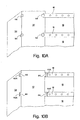
Fig. 8A is a left side view cross section of the enclosure shown inFig. 1 with one embodiment of a partition according to the invention having multiple vents or holes; -
Fig. 8B is a cross-section perspective of a portion of the partition shown inFig. 8A . -
Fig. 8C is a top view cross section of the enclosure shown inFig. 1 with the top panel removed illustrating one embodiment of the partition shown inFig. 8A . -
Fig. 9 is a front view of the enclosure shown inFig. 1 with the front door removed illustrating another embodiment of one or more partitions according to the invention; -
Figs. 10A-10B are cut-away perspective views of portions of one or more partitions within the enclosure shown inFig. 1 according to the invention; -
Fig. 11 is a top view cross section of the enclosure shown inFig. 1 illustrating a first mode of airflow according to the invention; -
Fig. 12 is a top view cross section of the enclosure shown inFig. 11 with the top panel removed illustrating one embodiment of the first mode of airflow. -
Fig. 13 is a top view cross section of the enclosure shown inFig. 1 with the top panel removed illustrating a second mode of airflow according to the invention; -
Fig. 14A is a top view cross section of the enclosure shown inFig. 1 with the top panel removed illustrating a third mode of airflow according to the invention; -
Fig. 14B is a perspective view of a duct unit and an electronic component that uses side-to-side airflow for cooling and ventilating. -
Fig. 14C is a perspective view of duct units in relation to electronic components that use side-to-side airflow. - Fig. 15A is a top view cross section of the enclosure of
Fig. 1 with the top panel removed illustrating one embodiment of the enclosure interior to permit airflow illustrated inFig. 14A . - Fig. 15B is a top view cross section of the enclosure of
Fig. 1 with the top panel removed illustrating another embodiment of the enclosure interior to permit airflow illustrated inFig. 14A ; -
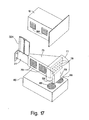
Fig. 16 is a perspective view of the enclosure shown inFig. 1 with the front door, the side panel and the top panel removed and including an air distribution unit mounted therein; and -
Fig. 17 is an exploded perspective view of the air distribution system shown inFig. 16 and the duct unit shown inFig. 14A-14C . - Aspects of the invention include an equipment rack enclosure having an interior configured for facilitating defined airflow conditions within the enclosure to meet cooling and ventilating requirements of rack-mounted equipment where the enclosure interior is structured and/or arranged to permit front-to-back airflow, e.g., used by information technology (IT) equipment, and side-to-side airflow, e.g., used by certain types of telecommunications equipment. An exemplary enclosure includes at least a first air intake plenum defined in the enclosure interior and disposed to contain cooling air that is directed and/or diverted from a front-to-back airflow to permit air to flow side-to-side through one or more sections of a rack. Different embodiments of an enclosure according to the invention permit an enclosure interior to be configured or adapted to accommodate different dimensions, e.g., depths, of different types of electronic equipment, while permitting airflow to meet the cooling and ventilating requirements of the different types of equipment. Embodiments according to the invention permit an enclosure to simultaneously contain telecommunications equipment and IT equipment such that cooling and ventilating requirements of each type of equipment are met.
- Referring to
Fig. 1 , anequipment rack enclosure 10 includes anenclosed housing 12 and arack 14. Thehousing 12 is configured and sized to define an interior 13 sufficient to contain or enclose therack 14. In one embodiment, the housing is configured and sized to enclose therack 14 in a substantially centered position. Thehousing 12 includesside panels rack 14 to enclose therack 14 and to define thehousing 12. In one embodiment, thehousing 12 further includes a ventedrear panel 24 and a vented front panel ordoor 30. Thefront door 30 and therear panel 24 of thehousing 12 are configured and arranged to permit airflow through therack 14. Thedoor 30 is disposed to permit cooling air, e.g., ambient air of an equipment room or data center, to flow throughmultiple air vents 30A defined in thedoor 30 to thehousing interior 13. Therear panel 24 is disposed to permit exhaust air to flow throughmultiple vents 24A defined in therear panel 24 to an area external to thehousing interior 13. In one embodiment, the housing further includes atop panel 15 and abottom panel 19 that further define thehousing 12. - In one embodiment, the
rack 14 includes four vertical mountingrails components 17 and/ortelecommunications components 18, are disposed. Therack 14 can further include one or more horizontal mountingmembers 16 that extend from a front portion to a back portion of thehousing 12 to help to define the equipment area and to mount theequipment front mounting rails rack 14 can be connected to front ends of one or more of the mountingmembers 16 and theback mounting rails members 16 to help to define therack 14 and the equipment area. One or more of the mountingrails top panel 15, thebottom panel 19, theside panels front door 30 and therear panel 24 to position and securely dispose therack 14 within thehousing interior 13. - The mounting
rails equipment components equipment components front mounting rails IT components 17, to be mounted at a desired vertical height and depth in therack 14, depending upon the U height, depth and other dimensions of the equipment. The mountingrails housing 12 such that theequipment components 17 are approximately centered when rack-mounted. - Embodiments of the
enclosure 10 according to the invention can include the mountingrails members 16 to rack-mount a mix of different types of equipment components, such as a mix of the IT andtelecommunications components - In one embodiment, the
enclosure 10 is sized to enclose therack 14 having a 19-inch width W1 or a 23-inch width W1. Therack 14 is configured to accept and to mount theequipment components rack 14 can have a 23-inch width W1 and can be further configured to accept and to mount exclusively equipment having a 19-inch width, e.g., theIT components 17, or equipment having a 23-inch width, e.g., thetelecommunications components 18. In another embodiment, the 23-inch rack 14 can be further configured to accept and to mount simultaneously a mix of equipment having either a 19-inch or a 23-inch width, e.g., a mix of the IT and thetelecommunications components - The
enclosure 10 can have overall dimensions to house therack 14 such that, for example, thespace 46 along the left side of therack 14 is sized to help to increase/optimize airflow along the left side of therack 14, as described below in further detail. In different embodiments of the invention, therack 14 can be moved from a center position within theenclosure 10 to increase one of theopen spaces - In one embodiment, the
enclosure 10 can have overall dimensions to accommodate therack 14 with a 23-inch width W1. In this embodiment, the 23-inch enclosure 10 is sized to house therack 14 having either a 19-inch or 23-inch W1, thereby providing theenclosure 10 with flexibility and adaptability with respect to the types ofequipment enclosure 10 can have a width ranging from, but not limited to, about 24 inches to about 30 inches or more. The invention, however, is not limited to theenclosure 10 having specific overall dimensions, and, in particular, is not limited to a certain width and anticipates dimensions to accommodate different sizes and widths of therack 14 and/or theequipment equipment components rack 14, and to help to increase/optimize airflow in thehousing interior 13. Promoting and increasing airflow in thehousing interior 13, e.g., along the left side of therack 14, helps to configure side-to-side airflow conditions within thehousing interior 13. - Referring to
Fig. 2 illustrating a top view cross-section of theenclosure 10, and with further reference toFig. 1 , in one embodiment, thehousing interior 13 is configured to define at least a firstair intake plenum 20 along a left side of therack 14 in theopen space 46 between theside panel 26 and therack 14. Thehousing interior 13 is further configured to define a firstexhaust air plenum 22 along a side and back portion of theenclosure 10. One or more barriers orpartitions spaces side panels rack 14 to help to define the firstair intake plenum 20 and/or theexhaust plenum 22. The firstair intake plenum 20, as described below in further detail, is a substantially enclosed configuration that is constructed and arranged along the left side of therack 14 to receive and to contain cooling air from which equipment using side-to-side airflow for cooling may drawn from to meet its cooling and ventilating needs. Thefirst intake plenum 20 defined within thehousing interior 13 thereby helps to configure a side-to-side airflow used by thetelecommunications equipment 18. - The one or more barriers or
partitions air intake plenum 20 from theexhaust plenum 22, and to thereby help to prevent circulation of exhaust air from theexhaust plenum 22 into the firstair intake plenum 20. As will be described in further detail below, thepartitions housing interior 13 to accommodate the different dimensions and, in particular, the different depths of theequipment top panel 15 and thebottom panel 19 of thehousing 12 can further define thefirst intake plenum 20 and/or theexhaust plenum 22. - In one embodiment, the
first intake plenum 20 is substantially enclosed having anopen end 20A in fluid communication with a front portion of thehousing interior 13 or anair intake side 25 of therack 14. As shown inFig. 2 , theplenum 20 is disposed and configured to receive laterally directed and/or diverted flow of cooling intake air drawn into thehousing 12 from theair vents 30A in thedoor 30 along the front portion of thehousing interior 13 and/or theair intake side 25 of therack 14. Thefirst intake plenum 20 is further configured to contain sufficient cooling air from which air intakes of the equipment using side-to-side airflow, e.g., thetelecommunications equipment 18, can draw from. In addition, thefirst intake plenum 20 can be further configured to limit air to flow in a side-by-side configuration through equipment in therack 14 using side-to-side airflow. - The
first intake plenum 20 is further disposed and configured to prevent/reduce air loss from theplenum 20 and to prevent/reduce airflow from thefirst intake plenum 20 to theexhaust plenum 22. Thefirst intake plenum 20 helps to prevent/reduce exhaust air from circulating to theair intake side 25 and into theplenum 20. Theplenum 20 and the top andbottom panels rack 14 to theair intake side 25 and into theplenum 20. Theplenum 20 is essentially disposed and configured or set up within thehousing interior 13 to separate cooling intake air drawn into the front portion of thehousing interior 13 from hot and warm exhaust air vented along the back portion of therack 14. Separating cooling air from exhaust air prevents/minimizes the circulation of exhaust air to theair intake side 25 and theplenum 20, and prevents/minimizes mixing of cooling air with exhaust air during operation of theequipment - In one embodiment, as shown in
Figs. 1-2 , one ormore partitions rack 14 between theside panel 26 and one or more of themembers 16 extending front-to-back along the left side of therack 14 to define thefirst intake plenum 20. The one ormore partitions first intake plenum 20 and theexhaust plenum 22 and to thereby help to separate cooling intake air within theplenum 20 from exhaust air vented to theexhaust plenum 22. - Referring to
Fig. 3 illustrating a front view of thehousing interior 13, and with further reference toFigs. 1-2 , in one embodiment, onepartition 32 is disposed in a substantially parallel orientation to theleft side panel 26 and theother partition 34 is disposed in a substantially perpendicular orientation to theleft side panel 26. Thepartitions first intake plenum 20. In one embodiment, thepartition 32 disposed substantially parallel to theleft side panel 26 extends vertically along at least a portion of the height H1 of therack 14, and thepartition 34 disposed substantially perpendicular to theleft side panel 26 similarly extends vertically along at least a portion of the rack height H1 to define thefirst intake plenum 20. - In another embodiment, the
partition 32 disposed substantially parallel to theleft side panel 26 can be disposed and connected to themember 16 of therack 14 such that thepartition 32 extends from themember 16 to theleft side panel 26 to help to define thefirst intake plenum 20, thereby eliminating the need for thepartition 34. - Referring further to
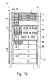
Figs. 1-2 , thepartition 38 on the right side of therack 14 is disposed and configured to help to define a frontair intake plenum 23. The frontair intake plenum 23 can include the front portion of the interior 13 of thehousing 12 between thedoor 30 and therack 14. The frontair intake plenum 23 is configured and sized to receive air drawn into the front portion of thehousing interior 13 from the vented front panel ordoor 30 along theair intake side 25 of therack 14. Thepartition 38 is further configured to help to define theexhaust plenum 22. Thepartition 38 is disposed in a substantially perpendicular orientation to theright side panel 28 of thehousing 12 and extends vertically along at least a portion of the height H1 of therack 14 and/or thehousing interior 13. Thepartition 38 is further configured to form a substantially airtight barrier between thefront intake plenum 23 and theexhaust plenum 22. Thepartition 38 thereby helps to prevent airflow from the front portion of therack 14 to theexhaust plenum 22, and helps to prevent exhaust air from circulating to the first and thefront intake plenums right side partition 38, along with thepartitions rack 14, separate cooling intake air drawn into thehousing interior 13 by theequipment exhaust plenum 22. - Referring to
Fig. 4A illustrating a left side view cross section of theenclosure 10, and with further reference toFig. 3 , in one embodiment, thepartitions rack 14 and/or thehousing interior 13 to help to define thefirst intake plenum 20 between theleft side panel 26 and theequipment components - Referring to a left side view cross section illustrated in
Fig. 4B , in another embodiment, eachpartition rack 14 and/or thehousing interior 13 to the extent or the U heights of thetelecommunications components 18 mounted vertically in therack 14. In this case, afront partition 35 and abottom partition 36 are disposed in thespace 46 to help to define thefirst intake plenum 20 and to limit its configuration to the extent of thetelecommunications components 18 in therack 14. Thefront partition 35 is connected at a front side of therack 14, e.g., either to therack 14 or, if present, to a side or front portion of themember 16. Thefront partition 35 extends to theleft side panel 26 of thehousing 12 in a substantially perpendicular orientation to thepanel 26 and downward along the H1 of therack 14 to thebottom panel 19. Thefront partition 35 is connected or joined to the bottom panel in an appropriate manner and by appropriate means, as described below in further detail. Thebottom partition 36 extends from a front to a back portion of therack 14 along the left side of therack 14 in a substantially parallel orientation to thebottom panel 19. As shown inFig. 4B , the front and thebottom partitions bottom partition 36 is joined or connected in an appropriate manner and by appropriate means to a portion, e.g., a bottom edge, of each of thepartitions partitions plenum 20 to those sections of the equipment area of therack 14 in which thetelecommunications components 18 are mounted. Theplenum 20 is essentially configured to receive cooling intake air drawn from the front portion of thehousing interior 13 and/or theintake side 25 of therack 14, and to contain cooling air to facilitate a side-to-side airflow condition thetelecommunications components 18 use for cooling and ventilating. - Referring to
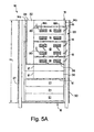
Figs. 5A-5B , and with further reference toFigs. 4A-4B , in one embodiment, multiple blankingpanels 21 can be mounted to one or more of the mountingrails members 16 along each side or the front of therack 14 to block sections of the equipment area that are vacant or include components that use front-to-back airflow, e.g., theIT components 17. The blankingpanels 21 help to prevent air loss from the first andfront intake plenums rack 14, and/or from interfaces of thecomponents rack 14. As shown inFig. 5A , multiple blankingpanels 21 can be mounted to the mountingrails members 16 at sections of therack 14 along its left side that include thecomponents multiple blanking panels 21 cover thecomponents 17 and the vacant sections to help to prevent/minimize air loss from the left side of therack 14. As shown inFig. 5B , illustrating a right side view cross section of theenclosure 10 and the exhaust side of thetelecommunications components 18, multiple blankingpanels 21 can be similarly mounted to the mountingrails members 16 to cover theIT components 17 and the vacant sections of therack 14 along the right side of therack 14. - In one embodiment, use of the blanking
panels 21 can help to permit air to flow upward over a top of therack 14, as shown byarrows 80 inFigs. 5A-5B , and to facilitate flow of hot and warm exhaust air vented from the exhaust vents 18B of thetelecommunications components 18. Exhaust air within theexhaust plenum 23 can circulate, e.g., in upward and/or downward orientation, as shown byarrows 82 inFig. 5B . The blankingpanels 21 thereby help to facilitate circulation of air over the top of therack 14 and within theexhaust plenum 23 before it is vented through therear panel 24, which helps to lower air resistance within thehousing interior 13. - Referring to
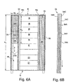
Figs. 6A-6B , in one embodiment, one or more of thepartitions components partitions Fig. 6A , thepartition 34 positioned on the left side of therack 14 can include two or more overlapping partitions 34a disposed within a mounting frame 34b. The mounting frame 34b can have appropriate dimensions, e.g., a height H2 and a width W2, such that the frame 34b can seat in thespace 46 defined between theleft side panel 26 and therack 14. In one embodiment, the frame 34b can be constructed and arranged to be removably connected to one or more of the leftside mounting rails rack members 16, thetop panel 15, thebottom panel 19 and theside panel 26 to securely position the frame 34b. - In another embodiment, the frame 34b can have dimensions and be constructed such that when the frame 34b is seated in the
space 46, an outer perimeter of the frame 34b can bias against one or more of therack members 16, thetop panel 15, thebottom panel 19 and theside panel 26 to position the frame 34b within thehousing interior 13. - As shown in
Fig. 6B , a side view cross section of the mounting frame 34b is provided and illustrates that the partitions 34a can be slidably disposed in an overlapping arrangement within the frame 34b such that each partition 34a can slide across an adjacent partition 34b. In one embodiment, each of the partitions 34a is slidably mounted within a track or groove 34c defined vertically in an inner surface of the frame 34b. The partitions 34a can be pulled vertically along the height H2 of the frame 34b in a downward/upward direction to extend or shorten the overlapping partitions 34a as needed. - As shown in
Fig. 6A , the partitions 34a can be extended or shortened to define a height H3 of thefirst intake plenum 20 such that the height H3 of theplenum 20 can correspond to the location and the U height of, for example, thetelecommunications components 18 in therack 14. In one embodiment, the partitions 34b can be extended fully along the entire height H1 of therack 14 and/or thehousing interior 13. - As noted above, one or more of the
partitions Fig. 6A , thepartition 38 disposed on the right side of therack 14, for example, can be a single partition 38a disposed in a mounting frame 38b. The mounting frame 38b is similar to the frame 34b disposed on the left side of therack 14, and has appropriate dimensions such that the frame 38b can seat in thespace 48 defined between theright side panel 28 and therack 14. Like the frame 34b disposed on the left side of therack 14, the frame 38b can be constructed and arranged to be removably connected by one or more of the above-describedfasteners 44, or can have dimensions and be constructed to permit the frame 38b to bias against one or more of therack members 16, thetop panel 15, thebottom panel 19 and theside panel 26 when seated in thespace 48. - Referring to
Figs. 7A-7B , in one embodiment, thepartitions panels 21 can be configured and disposed along the left side of therack 14 to accommodate different depths and U heights of the rack-mountedequipment components Figs. 7A-7B , the IT andtelecommunications components rack 14 can have different depths depending upon the type of thecomponent partitions panels 21 can be constructed and arranged in different arrangements and configurations to accommodate space or area defined between theequipment components rail 14c or theother partition 34 that results from the different depths of the rack-mountedcomponents partitions panels 21 can thereby help to define and configure thefirst intake plenum 20 along the left side of therack 14 in response to changes of the mix of theequipment rack 14. - As shown in
Figs. 7A-7B , in one embodiment, thepartition 32 can be configured in one or more separate sections disposed along the left side of therack 14 wherein a single section or two or more sections of thepartition 32 define a height that corresponds to the U height of one ormore components components partition 34 or therail 14c. In one embodiment, one or more sections of thepartition 32 can have a configuration and arrangement similar to the overlapping partitions 34a shown inFig. 6A and include overlappingpartitions 32a disposed in a mountingframe 32b. The mountingframe 32b holds thepartitions 32a in an overlapping manner such that eachpartition 32a can slidably move over anadjacent partition 32a. Thepartitions 32a can be slidably moved upward/downward in a vertical direction to extend/reduce a length of thepartition 32a, as shown inFig. 7A , or can be slidably moved forward/backward in a horizontal direction to widen/narrow a width of thepartition 32a, as shown inFig. 7B . The mountingframe 32b can be sized and configured such that theframe 32b seats between thecomponents partition 34 or the left back mountingrail 14c. In another embodiment, theframe 32b can be removably joined or connected to therail 14c, one or more of the mountingmembers 16, thepartition 34 and/or the top orbottom panel - Referring further to
Figs. 7A-7B , in different embodiments, the overlappingpartitions 32a can be joined or connected removably and directly to therail 14c, one or more of themembers 16, thepartition 34 and/or the top orbottom panel partition 32a can be coupled to anadjacent partition 32a such that thepartitions 32a are immobile. In another embodiment, eachpartition 32a can be slidably coupled to anadjacent partition 32a such that thepartitions 32a can slide across or against each other in either an upward/downward orientation or a forward/backward orientation. Movement of theadjacent partitions 32a adjusts the height or the depth of the overlappingpartitions 32a to accommodate the different depths and U heights of thecomponents Figs. 7A-7B , each of the blankingpanels 21 can have different lengths to accommodate the different depths of theequipment components partitions 32b and/or the multiple blanking panels help to define the firstintake air plenum 20 and to form an airflow blocking barrier between thefirst intake plenum 20 and theexhaust plenum 22. - In a further embodiment, a blanking
partition 37 can be incorporated along the left side of therack 14, as shown inFigs. 7A-7B . Like themultiple blanking panels 21, thepartition 37 can help to block sections of the equipment area of therack 14 that are vacant or include components that use front-to-back airflow, e.g., theIT components 17. Thepartition 37 can help to prevent air loss from the first andfront intake plenums rack 14, and/or from interfaces of thecomponents 17 and surfaces of therack 14. Thepartition 37 can include a set of overlapping partitions 37a disposed in a mountingframe 37b. Theframe 37b can be similarly configured as the frame 34b shown inFig. 6B . In one embodiment, the partitions 37a can be vertically moved upward/downward in to extend/reduce a length of the partitions 37a. - As shown in
Fig. 7A , in one embodiment, thepartition 34 extending perpendicular to therack 14 can extend the height H1 of therack 14. Thepartition 32, the overlappingpartitions 32a and the blanking panels, therefore, can be joined or connected in an appropriate manner by appropriate means, as described below in further detail. As shown inFig. 7B , in another embodiment, thepartition 34 can extend along the height H1 of therack 14 only to the extent of the U heights of thecomponents 18 using side-to-side airflow. In this case, thepartition 36 extending front-to-back along the left side of therack 14 is joined or fastened to thepartitions partitions 32a are joined or connected to the left back mountingrail 14c in an appropriate manner by appropriate means to form an airflow blocking barrier. - Referring to
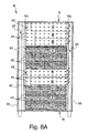
Figs. 8A-8B , in one embodiment, apartition 39 is disposed along the left side of therack 14. In one embodiment, thepartition 39 can extend from the front mountingrail 14b to theback mounting rail 14c and substantially along the height H1 therack 14. In another embodiment, thepartition 39 can extend along a portion of the height H1 of therack 14 to the extent or U heights of adjacent components using side-to-side airflow, e.g., thetelecommunications equipment 18. In one embodiment, thepartition 39 can be removably joined or connected to one or more of therails side mounting members 16 and/or the top orbottom panel - As shown in a front view of a portion of the
partition 39 inFig. 8B , thepartition 39 is constructed of a single sheet ofmaterial 40, e.g., a heat resistant polyethylene, that defines multiple vents oropenings 41 substantially across its height and width and has a removable covering orfilm 42, e.g. Mylar®, over its surface. In one embodiment, during installation, thepartition 39 is coupled directly to the left side of therack 14 adjacent to theequipment components film 42 is slit or cut using an appropriate means, e.g., a cutting edge or knife, and thereafter removed or manually peeled from the surface of thematerial sheet 40. Removal of the covering 42 permits the multiple vents oropenings 41 to be exposed and to thereby permit air to pass therethrough. When coupled to the left side of therack 14, the multiple vents oropenings 41 permit air to flow from thefirst intake plenum 20 intoair intakes 18A disposed along the side of thecomponents 18. - As shown in
Fig. 8B , in one embodiment, the cover orfilm 42 can include printed markings orother indicia 43 to indicate the location of thecomponents 18 using side-by-side airflow when thepartition 39 is coupled to therack 14. In one embodiment, themarkings 43 can indicate the location of the air intake vents 18A of thecomponents 18 such that the multiple vents oropenings 43 exposed by removing the covering orfilm 42 will correspond and/or substantially align with the intake vents 18A when thepartition 39 is coupled to therack 14. The multiple vents oropenings 43 can help to optimize/increase airflow from thefirst intake plenum 20 into theintake vents 18A and through thecomponents 18 to configure side-to-side airflow. - In one embodiment, only a portion of the covering or
film 42 is removed from thesheet material 40 to the extent of the distribution/location and/or the U heights of thecomponents 18 mounted in therack 14 using side-by-side airflow. Depending upon the distribution/location of thecomponents 18 and the mix of the rack-mounted IT andtelecommunications equipment partition 39 can either extend the entire height H1 of therack 14, or can be limited and extend only along a portion of therack 14 containing thecomponents 18 using side-to-side airflow. After installation of thepartition 39 and the cutting and removal of the covering orfilm 42, thepartition 39 can be adjusted to meet a reconfiguration of therack 14 and a different mix or distribution ofequipment openings 43 to accommodate changes in airflow requirements. The multiple vents oropenings 41 that no longer correspond to the air intake vents 18A of the components are thereby covered to help to prevent/minimize air loss. - Referring to
Fig. 8C , thepartition 39 can extend from the leftfront mounting rail 14b to the left back mountingrail 14c. In one embodiment, the left front and back mountingrails first intake plenum 20. As described below in further detail, in different embodiments, therack 14 can have a relatively wide width W1, e.g., 23-inches, and theenclosure 10 can be sized such that the leftfront mounting rail 14c substantially fills thespace 46 between the leftfront mounting rail 14b and theside panel 26, and the left back mountingrail 14c substantially fills thespace 46 between the leftback mounting rail 14c and theside panel 26. Thepartition 39 is removably joined or connected to the left front and back mountingrails first intake plenum 20. - As shown in
Fig. 8C , thepartition 39 is spaced from the left side of therack 14 and theequipment partition 39 and therack 14 and theequipment area 90 sufficient to permit movement of one or more of thecomponents rack 14. In one embodiment, one or more of thecomponents rack 14 such that, when desired, the one ormore components rack 14 toward the front portion of thehousing 12. The one ormore components rack 14, with or without removal from therack 14, to permit inspection, repair and/or replacement of thecomponents - In one embodiment, one or
more brush grommets 91 are disposed in thearea 90 between therack 14 and thepartition 39 to permit horizontal movement or a sliding motion of thecomponents rack 14, while serving as airblocking barriers to prevent air loss from thearea 90. The one ormore brush grommets 91 are further configured to prevent mixing of exhaust air circulating in theexhaust plenum 22 with cooling intake air contained in thefirst intake plenum 20. In another embodiment, one or more gaskets or brush grommets can be disposed between therack 14 and thepartition 39 along that portion of thepartition 39 from which the covering orfilm 42 has been removed. The one or more gaskets or brush grommets can be disposed along a perimeter of an area of thepartition 39 defined by removal of the covering orfilm 42. The one or more gaskets or brush grommets can be disposed and configured help to form a seal between therack 14, theequipment partition 39 such that air loss is prevented/minimized. - Referring to
Fig. 9 , in one embodiment, one or more of thepartitions brush grommet 80. In one embodiment, the gasket orbrush grommet 80 can include the mountingframe brush grommet 80 is disposed in thehousing interior 13 in a desired position adjacent to therack 14. The gasket or brush grommets orpartitions first intake plenum 20, theexhaust plenum 22 and thefront intake plenum 23. The gasket or brush grommets orpartitions rack 14 and along the left and/or the right side of thehousing interior 13 to provide for cabling and power requirements. The gasket and brush grommets orpartitions front intake plenum exhaust plenum 22, prevent/minimize circulation of exhaust air to intakes of theequipment components - Referring to
Figs. 10A-10B , in one embodiment, one or more of thepartitions appropriate fasteners 44 to one or more of themembers 16, thetop panel 15, thebottom panel 19, theside panels rear panel 24 to securely dispose thepartitions housing interior 13.Appropriate fasteners 44 are preferably constructed and arranged to permit quick connection to and removal from, e. g. , themembers 16, to enable thehousing interior 13 to be easily configured in response to different types, sizes and U heights of the IT andtelecommunications components components rack 14. -
Preferred fasteners 44 can include, but are not limited to, screws, tabs, snap tabs, VELCRO® strips, and the like, which permit thepartitions appropriate fastener 44 would depend on a material with which one or more of thepartitions partition Fig. 6A , in one embodiment, thepartition 32 along the left side of therack 14 can be removably connected to one or more of themembers 16 by means of a metal snap or VELCRO® strip-like fastener 44, wherein an edge of thepartition 32 butts an end or overlaps with the end of amember 16 and is connected thereto by thefastener 44. Similarly, thepartition 32 can be removably connected to theadjacent partition 34 by similar means to help to define thefirst intake plenum 20. - As shown in
Fig. 10A , in one embodiment, thepartition 32 can be configured to include along a side edge one ormore tabs 44 disposed and configured to be removably inserted into correspondingslots 44A defined in one or more of themembers 16 to removably fasten or connect thepartition 32 to the rack. Thepartition 32 can be further configured to include thetabs 44 on its opposite side to connect to theadjacent partition 34 to define thefirst intake plenum 20. In another embodiment, thepartitions partitions rack 14. - The
partitions partitions partitions partitions housing interior 13. In addition, a material of construction can be dependent on the extent and frequency with which thehousing interior 13 will be reconfigured to accommodate the cooling and ventilating needs of theequipment - The invention is not limited to the construction and arrangement of the
partitions panels 21 as described above, and includes other barriers and/or partitions as well as other configurations and arrangements of thepartitions front intake plenums exhaust plenum 23, as well as to help to configure or set up thehousing interior 13 to facilitate front-to-back airflow and/or side-to-side airflow as needed. In particular, the invention includes various configurations and arrangements of barriers and/or partitions to accommodate therack 14 containing exclusively IT ortelecommunications components telecommunications components equipment - Other features of the
enclosure 10 according to the invention help to facilitate airflow within thehousing interior 13 to achieve a front-to-back airflow configuration and/or a side-to-side airflow configuration. As noted above, the venteddoor 30 defines themultiple air vents 30A to permit air, e.g., ambient air, to flow into the front portion of thehousing interior 13 and/or theair intake side 25 of therack 14. In one embodiment, thedoor 30 can be sufficiently perforated, e.g., themultiple air vents 30A are concentrated along the left side of thedoor 30, to promote airflow into thefirst intake plenum 20. As shown inFig. 3 , in one embodiment, one ormore gaskets 75, e.g., foam gaskets, can be disposed around perimeter edges of theequipment components components members 16 and betweenadjacent components front intake plenums - Referring to
Fig. 11 , a top view cross-section of theenclosure 10 illustrates a first mode of airflow through theenclosure 10 that can be achieved where thefront intake plenum 23 is in fluid communication with thefirst intake plenum 20. Thefirst intake plenum 20 receives at least a portion of airflow directed and/or diverted laterally from thefront intake plenum 23, as shown byarrow 51 inFig. 11 . To define a front-to-back airflow condition, cooling air is drawn from thevents 30A in thedoor 30 into thefront intake plenum 23 byair intakes 17A disposed in front portions of theIT components 17. The air intakes 17A draw air into the front portions of thecomponents 17. Drawn-in air flows from the front to back portions of theequipment 17 and is exhausted fromback vents 17B disposed in the back portions of thecomponents 17 in a front-to-back flow, as shown byarrows 50 inFig. 11 . To define a side-to-side airflow condition, cooling air is drawn from the door vents 30A and from thefront intake plenum 23 by theair intakes 18A disposed in side portions of thetelecommunications components 18, as shown byarrows Fig. 11 . The air intakes 18A help to draw and/or to divert laterally into thefirst intake plenum 20 at least some portion of the front-to-back airflow, as well as help to draw cooling air directly from the door vents 30A. Theintakes 18A along the side portions of theequipment 18 draw air from theplenum 20 into thecomponents 18. Drawn-in air flows from one side to an opposite side of thecomponents 18 and is vented fromback vents 18A disposed along the opposite side of thecomponents 18 in a side-to-side flow, as shown byarrows 52 inFig. 11 . Air vented from the IT and thetelecommunications components exhaust plenum 22 to an area external to thehousing 12, as shown byarrows 54 inFig. 11 . - Referring to
Fig. 12 , a top view cross section of theenclosure 10 illustrates embodiments of theenclosure 10 in which therack 14 has a relatively wide width W1, e.g., 23-inches, and is further configured such that the front vertical mountingrails rack 14 between therack 14 and eachside panel enclosure 10, as described with reference toFig. 11 , the left verticalfront mounting rail 14b can define multiple openings orvents 14e to permit air to flow into the firstair intake plenum 20 from the air intake vents 30A of thedoor 30 and from the front portion of thehousing interior 13 or theair intake side 25 of therack 14, as shown byarrow 51 inFig. 12 . The multiple vents oropenings 14e help to provide air to the firstair intake plenum 30 to thereby help to provide sufficient side-to-side airflow used by, for example, thetelecommunications equipment 18, for cooling, as shown byarrows 52 inFig. 12 . In one embodiment, the left vertical mountingrail 14b has the multiple vents oropenings 14e defined along at least a portion of the height H1 of therack 14. In another embodiment, the left vertical mountingrail 14b has the multiple vents oropenings 14e defined along a portion of the height H1 of therack 14 to the extent that theequipment components 18 using side-to-side airflow are mounted and distributed in therack 14. - Referring to
Fig. 13 , a top view cross-section of theenclosure 10 illustrates a second mode of airflow through theenclosure 10 that can be achieved wherein therack 14 is positioned at the front of thehousing 12 such that therack 14 and thepartition 38 help to define theexhaust plenum 22 only. In this embodiment, thefront intake plenum 23 is not defined in thehousing interior 13 and thepartition 38 is disposed behind thedoor 30. Thehousing interior 13 can accommodate therack 14 loaded exclusively with thetelecommunications components 18. Cooling air is drawn through theair vents 30A in thedoor 30 and flows directly into theplenum 20, as shown byarrows Fig. 13 . - Referring to
Figs. 14A-14B , in other embodiments of theenclosure 10 according to the invention, theenclosure 10 can include one ormore duct units 75 configured and sized for vertical mounting in therack 14. As shown in a top view cross section of theenclosure 10 inFig. 14A , theduct unit 75 can have overall dimensions to permit rack mounting within the equipment area of therack 14. Theduct unit 75 includes ahousing 76 defining an internal chamber orduct 77 that is configured to receive and to contain air. Theduct unit 75 further includes multiple front vents oropenings 78 defined in its front side and multiple side vents oropenings 79 defined in its left side when rack-mounted. Thechamber 77 of theduct unit 75 can be defined with overall dimensions such that it receives air from the multiplefront openings 78 and helps to direct air through theduct unit 75 to themultiple side openings 79 to thereby provide air to thefirst intake plenum 20. As shown inFig. 14A , in one embodiment, thehousing 76 of theduct unit 75 can be constructed and arranged such that the housing defines thechamber 77 with a configuration or shape, e.g., a funnel-like shape as shown inFig. 14A , that helps to direct or channel air from the multiplefront openings 78 to themultiple side openings 79 and thereby helps to increase volume or rate of airflow into thefirst intake plenum 20. - The
duct unit 75 is disposed in therack 14 and thechamber 77 is configured such that thechamber 77 receives and thereby captures at least some portion of front-to-back airflow from thefront intake plenum 20 in the front portion of thehousing interior 13 or from theair intake side 25 of therack 14, as shown byarrows 55 inFig. 14A . As equipment components using front-to-back airflow draw air from thefront vents 30A of thedoor 30 into thefront intake plenum 23 to configure front-to-back airflow conditions, as described above with reference toFigs. 11-12 and as shown by thearrows 50 inFig. 14A , theduct unit 75 helps to divert some portion of the front-to-back airflow to thefirst intake plenum 20 along the left side of therack 14, as shown byarrows 56 inFig. 14A , to provide for side-to-side airflow. - Referring further to
Figs. 14A-14B , in one embodiment, theduct unit 75 can include one ormore fans 73 disposed within thechamber 77. In one embodiment, one ormore fans 73 can be coupled to the multiplefront openings 78 where eachfan 73 is disposed and configured to draw in cooling air from thefront intake plenum 20 in the front portion of thehousing interior 13 or from theair intake side 25 of therack 14 into thechamber 77, as shown by thearrows 55 inFig. 14A . Thefans 73 are further configured to force drawn-in air into thechamber 77 and through themultiple side openings 79 into the firstair intake plenum 20, as shown by thearrows 56 inFig. 14B . In another embodiment, one ormore fans 73 can be coupled to themultiple side openings 78 where each fan is disposed and configured to draw cooling air through thechamber 77 and from the front intake plenum or theair intake side 25 of therack 14. The fans are further configured to force drawn-in air into thefirst intake plenum 20. In another embodiment, theduct unit 75 can include one ormore fans 73 coupled to the multiple front and theside openings - Referring to
Fig. 14C , and with further reference toFig. 14B , in one embodiment, thehousing 77 of theduct unit 75 can be constructed and arranged to define a certain U height and a certain depth to permit theduct unit 75 to be mounted vertically adjacent to and/or between theequipment components rack 14. Theduct unit 75 can be mounted in therack 14 at a desired position selected to correspond to the location and distribution of equipment using side-to-side airflow, such as thetelecommunications components 18. As shown inFig. 14C , theduct unit 75 can be mounted in therack 14 adjacent, e.g. above or below, and/or between theequipment components 18 using side-by-side airflow. As shown inFigs. 14B-14C , when mounted adjacent to or between theequipment components 18 using side-to-side airflow, theduct unit 75 can direct chamber air, e.g., drawn into thechamber 77 by theair intakes 18A of thecomponents 18 and/or forced or drawn into thechamber 77 by thefans 73 coupled to the multiple front and/orside openings multiple side openings 79 into thefirst intake plenum 20. Theduct unit 75 thereby vents cooling air proximate to the side vents 18A of thecomponents 18, as shown byarrows 57 inFigs. 14B-14C . The side vents 18A can draw air from themultiple side openings 79 of theduct unit 75 to thereby help to draw sufficient intake air for cooling in a side-to-side condition. - Referring to Fig. 15A, a top view cross section of the
enclosure 10 illustrates one embodiment of theenclosure 10 illustrated inFigs. 14A-14C in which therack 14 has a relatively wide width W1, e.g., 23-inches, and is further configured such that the front vertical mountingrails rack 14 between therack 14 and eachside panel front mounting rail 14b can define themultiple vents 14e to permit air to flow into the firstair intake plenum 20 from the air intake vents 30A of thedoor 30 and from the front portion of thehousing interior 13 or theair intake side 25 of therack 14, as shown by thearrow 51 in Fig. 15A and as described with reference toFig. 11-12 . - Referring to Fig 15B, is another embodiment of the
enclosure 10 shown in Fig. 15A, thepartition 32 can extend from theequipment rail 14c to help to define thefirst intake plenum 20. In different embodiments, thepartition 32 can include various configurations and arrangements are described above with reference toFigs. 6A-6B ,7A-7B and/or8A-8C . - Referring to a perspective view of the
enclosure 10 inFig. 16 , a third mode of airflow through theenclosure 10 can be achieved where thefront intake plenum 23 is in fluid communication with one or more openings in thebottom panel 19 of thehousing 12. The one or more openings can serve to provide cooling air into thehousing interior 13 such that the cooling air flows into thefront intake plenum 23 and circulates upward vertically along the front portion of thehousing interior 13 or along theair intake side 25 of therack 14. As shown inFig. 16 , in one embodiment, each of the one or more openings in thebottom panel 19 is coupled to a plenum orduct 60 that extends externally from thebottom panel 19 and connects with a conventional raisedfloor configuration 67. The raisedfloor configuration 67 is well known in the art and can include a first floor and a second floor that define a conduit therebetween, wherein the conduit is connected to an air cooling unit or system that supplies cool air to the conduit. The conduit receives cool air from the cooling unit or system and directs the cool air into the one ormore ducts 60 to supply cooling air to thehousing interior 13. - Still referring to
Fig. 16 , in another embodiment, the one ormore ducts 60 can be coupled to a rack-mountedair distribution unit 65, as disclosed in the applicants' copending patent application Serial No.10/121,313 air distribution unit 65 is disposed along and/or coupled to thebottom panel 19 within thehousing interior 13 and coupled to the raisedfloor configuration 67 through the one ormore ducts 60 to receive and/or to draw in cool air.Multiple fans 66 of theunit 65 can draw cooling air from theducts 60 into thefront intake plenum 23 and can circulate cooling air upward along the front portion of thehousing interior 13 or along theair intake side 25 of therack 14 to configure a bottom-to-top airflow, as shown byarrows 59 inFig. 16 . In another embodiment, multiple fans are not connected to theducts 60 and are configured to draw in ambient air external to theenclosure 10 into thesystem 65 for distribution upward as cooling air in bottom-to-top airflow condition, as described. - As shown in
Fig. 16 , theenclosure 10 is configured such that cooling air can be received by the first intake and thefront intake plenums unit 65, as described above and shown byarrows 59 inFig. 16 . In this case, a bottom-to-top airflow condition is defined as cooling air is forced and/or drawn upward through thefront intake plenum 23 along the front portions of theIT components 17. The bottom-to-top airflow helps to contribute to a front-to-back airflow condition and a side-to-side airflow condition, for instance, by increasing the volume of the cooling air forced upward through thefront intake plenum 23 and received by thefirst intake plenum 20. In addition, theair distribution unit 65 forces the bottom-to-top airflow into the first and thefront intake plenums plenums plenums ducts 60 and theunit 65. - Referring to
Fig. 17 , in one embodiment, theenclosure 10 can include theair distribution unit 65, as described above, and can be further configured to rack-mount one or more of theduct units 75. As shown in an exploded perspective view ofFig. 17 , themultiple fans 66 of theair distribution unit 65 can draw in cooling air and force drawn-in air into thefront intake plenum 23 at the front portion of thehousing interior 13 or thefront intake 25 of therack 14 and upward in a bottom-to-top airflow condition, as shown by thearrows 59 inFig. 16 . The multiplefront openings 78 of one or more of theduct units 75 can receive or capture some portion of bottom-to-top airflow provided by theair distribution unit 75. In one embodiment, one or more of theduct units 75 includes one ormore fans 73 disposed within thechamber 77, as described above, to drawn in the bottom-to-top airflow theair distribution system 65 creates by forcing cooling air into thefront intake plenum 23 in the front portion of theenclosure interior 13. Theunit 65 and thefans 73 of theduct units 75 help to increase the volume and/or rate of flow of cooling air into thefirst intake plenum 20 and thereby help to pressurize thefirst intake plenum 20. Thefirst intake plenum 20 receives and contains cooling air under pressure, which helps to insure that theair intakes 18A of the side-to-side airflow components 18 have sufficient air from which to draw to meet its cooling needs. - In one embodiment, one or more of the
duct units 75 further includes a hood-like member 71 that is configured to couple with a front portion of theduct unit 75 and is further configured to be disposed in thefront intake plenum 23 or the front portion of thehousing interior 13. The hood-like member 71 is disposed within thehousing interior 13 and configured to capture some portion of cooling air forced upward in bottom-to top airflow to help to provide sufficient cooling air to thefirst intake plenum 20 via theduct unit 75. - Other embodiments are within the scope and spirit of the appended claims. For example, the
first intake plenum 20 can be disposed and configured on the right side of therack 14. Thepartitions space 48 between theright side panel 28 of thehousing 12 and therack members 16 running front-to-back along the right side of therack 14. - Another example includes embodiments wherein the vented
rear panel 24 of thehousing 12 can be configured to couple to an exhaust unit disposed externally along the rear of theenclosure 10 and having one or more fans for drawing and venting exhaust air, as disclosed in the applicants' copendingU.S. application Serial No. 10/303,641 , which is incorporated herein by reference. In one embodiment, the external exhaust unit can replace the ventedrear panel 24 and can be configured to serve as a back door of thehousing 12. Each fan of the exhaust unit is coupled to an exhaust duct defined within the exhaust unit interior. The exhaust duct is configured to receive air the fan draws in and vents into the exhaust duct and to direct fan-vented air to a top portion of the exhaust unit for venting to an area external to theenclosure 10. Each fan is disposed in fluid communication with theexhaust plenum 23 and the equipment vents 17A and 18A of thecomponents exhaust plenum 23 into the exhaust unit, and then vents drawn-in air into its associated duct. Fan-vented air is thereafter directed by the exhaust duct to the top of the exhaust unit for venting. - In another embodiment, the exhaust unit having one or more fans as described is disposed at a top of the
enclosure 10. Each fan draws air from theexhaust plenum 23 and vents drawn-in air to an area external to theenclosure 10. - Having thus described at least one illustrative embodiment of the invention, various alterations, modifications and improvements will readily occur to those skilled in the art. Accordingly, the foregoing description is by way of example only and is not intended as limiting. The invention's limit is defined only in the following claims and the equivalents thereto.
Claims (5)
- An equipment enclosure (10) comprising:an enclosure housing (12) having a front side (30), a first side (26), a second side (28), a back side (24), a top side (15) and a bottom side (19);an equipment frame (14) disposed within the internal area of the enclosure housing, such that a first side area (46) is formed between the first side of the enclosure housing and a first side of the equipment frame, a second side area is (48) is formed between a second side of the equipment frame and the second side of the enclosure housing, a front area is formed between the front side of the enclosure housing and a front side of the equipment frame, and a back area is formed between the back side of the enclosure housing and a back side of the equipment frame;a first internal panel (32,34) disposed between the first side of the equipment frame and the first side of the enclosure housing to provide a substantially air tight seal between the first side area and the back area and to define the first side area as a substantially enclosed intake air plenum (20) extending from the top side to the bottom side of the enclosure housing; anda second internal panel (38) disposed between the second side of the equipment frame and the second side of the enclosure housing to provide a substantially air tight seal between the second side area and the front area and to define the second side area as a substantially enclosed exhaust air exhaust plenum (22) extending from the top side and the bottom side of the enclosure housing, the exhaust air plenum being opposite to the intake air plenum.
- The enclosure of claim 1, wherein at least one of the front side and the bottom side include openings (30A) to allow air flow into the enclosure, and at least one of the top side and the back side include openings (24A) to allow air flow out of the enclosure.
- The enclosure of claim 1 or claim 2, further comprising at least one exhaust fan mounted to one of the top side of the enclosure and the back side of the enclosure to draw air from the back area.
- The enclosure of any preceding claim, further comprising at least one panel removably mounted between the first side area and an internal area of the equipment frame to block air flow between the first side area and a portion of the internal area of the equipment frame.
- The enclosure of any preceding claim, wherein the enclosure housing is a 23-inch enclosure housing and the equipment frame is a 19-inch wide equipment frame.
Applications Claiming Priority (2)
| Application Number | Priority Date | Filing Date | Title |
|---|---|---|---|
| US10/436,886 US7033267B2 (en) | 2003-05-13 | 2003-05-13 | Rack enclosure |
| EP04751315A EP1623611B1 (en) | 2003-05-13 | 2004-05-04 | Rack enclosure |
Related Parent Applications (2)
| Application Number | Title | Priority Date | Filing Date |
|---|---|---|---|
| EP04751315A Division EP1623611B1 (en) | 2003-05-13 | 2004-05-04 | Rack enclosure |
| EP04751315.5 Division | 2004-05-04 |
Publications (4)
| Publication Number | Publication Date |
|---|---|
| EP2252136A2 true EP2252136A2 (en) | 2010-11-17 |
| EP2252136A9 EP2252136A9 (en) | 2011-04-06 |
| EP2252136A3 EP2252136A3 (en) | 2015-05-20 |
| EP2252136B1 EP2252136B1 (en) | 2017-12-20 |
Family
ID=33417275
Family Applications (2)
| Application Number | Title | Priority Date | Filing Date |
|---|---|---|---|
| EP04751315A Expired - Lifetime EP1623611B1 (en) | 2003-05-13 | 2004-05-04 | Rack enclosure |
| EP10173917.5A Expired - Lifetime EP2252136B1 (en) | 2003-05-13 | 2004-05-04 | Rack enclosure |
Family Applications Before (1)
| Application Number | Title | Priority Date | Filing Date |
|---|---|---|---|
| EP04751315A Expired - Lifetime EP1623611B1 (en) | 2003-05-13 | 2004-05-04 | Rack enclosure |
Country Status (9)
| Country | Link |
|---|---|
| US (2) | US7033267B2 (en) |
| EP (2) | EP1623611B1 (en) |
| JP (1) | JP2007502027A (en) |
| CN (2) | CN102088838B (en) |
| AT (1) | ATE524958T1 (en) |
| DK (2) | DK2252136T3 (en) |
| ES (1) | ES2373384T3 (en) |
| HK (1) | HK1158878A1 (en) |
| WO (1) | WO2004103046A2 (en) |
Cited By (6)
| Publication number | Priority date | Publication date | Assignee | Title |
|---|---|---|---|---|
| WO2012135136A2 (en) * | 2011-03-25 | 2012-10-04 | Compuspace, Lc | Filler panels and systems |
| EP2879473A4 (en) * | 2013-04-30 | 2016-03-30 | Obschesctvo S Ogranichennoy Otvetstvennostyu Depo Electronics | Rack for a computer engineering apparatus |
| US9661782B2 (en) | 2012-03-30 | 2017-05-23 | International Business Machines Corporation | Data center cooling arrangements |
| US10091905B1 (en) | 2017-03-31 | 2018-10-02 | Yandex Europe Ag | Dual-action storage media chassis structure and system |
| EP3402318A1 (en) * | 2017-05-08 | 2018-11-14 | Panduit Corp | 4-post rack with integrated intake/exhaust regions |
| USD866562S1 (en) | 2017-03-31 | 2019-11-12 | Yandex Europe Ag | Storage media chassis |
Families Citing this family (148)
| Publication number | Priority date | Publication date | Assignee | Title |
|---|---|---|---|---|
| US7752858B2 (en) * | 2002-11-25 | 2010-07-13 | American Power Conversion Corporation | Exhaust air removal system |
| US7112131B2 (en) * | 2003-05-13 | 2006-09-26 | American Power Conversion Corporation | Rack enclosure |
| US7033267B2 (en) * | 2003-05-13 | 2006-04-25 | American Power Conversion Corporation | Rack enclosure |
| EP1784749A2 (en) * | 2004-09-02 | 2007-05-16 | Logiccon Design Automation Ltd. | Method and system for designing a structural level description of an electronic circuit |
| JP4599984B2 (en) * | 2004-10-20 | 2010-12-15 | 日本電気株式会社 | Rack, electronic device mounting apparatus, and cooling method thereof |
| JP2006294079A (en) * | 2005-04-06 | 2006-10-26 | Hitachi Ltd | Airflow regulation mechanism for disk array system |
| US8107238B2 (en) | 2005-09-19 | 2012-01-31 | Chatsworth Products, Inc. | Ducted exhaust equipment enclosure |
| US11212928B2 (en) | 2005-09-19 | 2021-12-28 | Chatsworth Products, Inc. | Vertical exhaust duct for electronic equipment enclosure |
| US7542287B2 (en) | 2005-09-19 | 2009-06-02 | Chatsworth Products, Inc. | Air diverter for directing air upwardly in an equipment enclosure |
| US7804685B2 (en) | 2005-09-19 | 2010-09-28 | Chatsworth Products, Inc. | Ducted exhaust equipment enclosure |
| US11259446B2 (en) | 2005-09-19 | 2022-02-22 | Chatsworth Products, Inc. | Vertical exhaust duct for electronic equipment enclosure |
| US7406839B2 (en) * | 2005-10-05 | 2008-08-05 | American Power Conversion Corporation | Sub-cooling unit for cooling system and method |
| US20070163748A1 (en) * | 2006-01-19 | 2007-07-19 | American Power Conversion Corporation | Cooling system and method |
| US8672732B2 (en) | 2006-01-19 | 2014-03-18 | Schneider Electric It Corporation | Cooling system and method |
| US7365973B2 (en) * | 2006-01-19 | 2008-04-29 | American Power Conversion Corporation | Cooling system and method |
| US20070171610A1 (en) * | 2006-01-20 | 2007-07-26 | Chatsworth Products, Inc. | Internal air duct |
| US7862410B2 (en) * | 2006-01-20 | 2011-01-04 | American Power Conversion Corporation | Air removal unit |
| US8257155B2 (en) | 2006-01-20 | 2012-09-04 | Chatsworth Products, Inc. | Selectively routing air within an electronic equipment enclosure |
| US20110123036A1 (en) * | 2006-03-02 | 2011-05-26 | Yossi Barath | Muffled rack and methods thereof |
| US7604535B2 (en) * | 2006-04-27 | 2009-10-20 | Wright Line, Llc | Assembly for extracting heat from a housing for electronic equipment |
| US20090239460A1 (en) * | 2006-04-27 | 2009-09-24 | Wright Line, Llc | Assembly for Extracting Heat from a Housing for Electronic Equipment |
| US8764528B2 (en) * | 2006-04-27 | 2014-07-01 | Wright Line, Llc | Systems and methods for closed loop heat containment with cold aisle isolation for data center cooling |
| US7558649B1 (en) * | 2006-05-03 | 2009-07-07 | Hewlett-Packard Development Company, L.P. | Method for predicting airflow rates |
| JP2007305754A (en) * | 2006-05-11 | 2007-11-22 | Kawamura Electric Inc | Heat shutter structure of cabinet rack |
| US7595985B2 (en) * | 2006-06-19 | 2009-09-29 | Panduit Corp. | Network cabinet with thermal air flow management |
| US8322155B2 (en) | 2006-08-15 | 2012-12-04 | American Power Conversion Corporation | Method and apparatus for cooling |
| US9568206B2 (en) | 2006-08-15 | 2017-02-14 | Schneider Electric It Corporation | Method and apparatus for cooling |
| US8327656B2 (en) | 2006-08-15 | 2012-12-11 | American Power Conversion Corporation | Method and apparatus for cooling |
| US20080041077A1 (en) * | 2006-08-15 | 2008-02-21 | American Power Conversion Corporation | Method and apparatus for cooling |
| US20080104985A1 (en) * | 2006-11-03 | 2008-05-08 | American Power Conversion Corporation | Constant temperature CRAC control algorithm |
| US7861543B2 (en) * | 2006-11-03 | 2011-01-04 | American Power Conversion Corporation | Water carryover avoidance method |
| US20080105753A1 (en) * | 2006-11-03 | 2008-05-08 | American Power Conversion Corporation | Modulating electrical reheat with contactors |
| US20080105412A1 (en) * | 2006-11-03 | 2008-05-08 | American Power Conversion Corporation | Continuous cooling capacity regulation using supplemental heating |
| US7681404B2 (en) | 2006-12-18 | 2010-03-23 | American Power Conversion Corporation | Modular ice storage for uninterruptible chilled water |
| US8425287B2 (en) | 2007-01-23 | 2013-04-23 | Schneider Electric It Corporation | In-row air containment and cooling system and method |
| US8328026B2 (en) * | 2007-02-22 | 2012-12-11 | Tellabs Operations, Inc. | Apparatus and method for configuring a dual rack-mountable chassis |
| JP5030631B2 (en) * | 2007-03-22 | 2012-09-19 | 富士通株式会社 | Cooling system for information equipment |
| US8152000B2 (en) * | 2007-04-26 | 2012-04-10 | Blackhawk Labs Llc | Apparatus and method for housing electronic equipment and increasing floor space utilization in a secure environment |
| US7764495B2 (en) * | 2007-04-30 | 2010-07-27 | Adc Telecommunications, Inc. | Telecommunication cabinet with airflow ducting |
| CN101755495B (en) | 2007-05-15 | 2013-10-16 | 美国能量变换公司 | Methods and systems for managing facility power and cooling |
| WO2008144678A1 (en) * | 2007-05-17 | 2008-11-27 | Chatsworth Products, Inc. | Electronic equipment enclosure with exhaust air duct and adjustable filler panel assemblies |
| JP2008294255A (en) * | 2007-05-25 | 2008-12-04 | Kawamura Electric Inc | Cabinet rack |
| US10028415B1 (en) | 2007-06-14 | 2018-07-17 | Switch, Ltd. | Electronic equipment data center and server co-location facility configurations and method of using the same |
| US8523643B1 (en) | 2007-06-14 | 2013-09-03 | Switch Communications Group LLC | Electronic equipment data center or co-location facility designs and methods of making and using the same |
| US9788455B1 (en) | 2007-06-14 | 2017-10-10 | Switch, Ltd. | Electronic equipment data center or co-location facility designs and methods of making and using the same |
| US9693486B1 (en) | 2007-06-14 | 2017-06-27 | Switch, Ltd. | Air handling unit with a canopy thereover for use with a data center and method of using the same |
| US9622389B1 (en) * | 2007-06-14 | 2017-04-11 | Switch, Ltd. | Electronic equipment data center and server co-location facility configurations and method of using the same |
| US9823715B1 (en) | 2007-06-14 | 2017-11-21 | Switch, Ltd. | Data center air handling unit including uninterruptable cooling fan with weighted rotor and method of using the same |
| US20090019875A1 (en) * | 2007-07-19 | 2009-01-22 | American Power Conversion Corporation | A/v cooling system and method |
| US20090030554A1 (en) * | 2007-07-26 | 2009-01-29 | Bean Jr John H | Cooling control device and method |
| US20090061755A1 (en) * | 2007-08-28 | 2009-03-05 | Panduit Corp. | Intake Duct |
| US7643291B2 (en) * | 2007-08-30 | 2010-01-05 | Afco Systems | Cabinet for electronic equipment |
| WO2009042735A1 (en) * | 2007-09-25 | 2009-04-02 | Blade Network Technologies, Inc. | Apparatus for externally changing the direction of air flowing through electronic equipment |
| US20140206273A1 (en) | 2007-11-19 | 2014-07-24 | Ortronics, Inc. | Equipment Rack and Associated Ventilation System |
| US7983038B2 (en) | 2007-11-19 | 2011-07-19 | Ortronics, Inc. | Equipment rack and associated ventilation system |
| US7907402B2 (en) * | 2007-11-09 | 2011-03-15 | Panduit Corp. | Cooling system |
| US10133320B2 (en) * | 2008-02-14 | 2018-11-20 | Chatsworth Products, Inc. | Air directing device |
| US8701746B2 (en) | 2008-03-13 | 2014-04-22 | Schneider Electric It Corporation | Optically detected liquid depth information in a climate control unit |
| US7515410B1 (en) * | 2008-04-23 | 2009-04-07 | International Business Machines Corporation | Hard disk drive carrier converter apparatus |
| GB2463956B (en) * | 2008-05-20 | 2010-11-03 | Semper Holdings Ltd | Rack mounted cooling unit |
| US10058011B2 (en) * | 2008-06-19 | 2018-08-21 | Panduit Corp. | Passive cooling systems for network cabinet |
| US9426903B1 (en) | 2008-06-27 | 2016-08-23 | Amazon Technologies, Inc. | Cooling air stack for computer equipment |
| BRPI0917974A2 (en) * | 2008-08-13 | 2015-11-17 | Bae Systems Plc | equipment refrigeration appliance |
| US7646602B1 (en) | 2008-08-29 | 2010-01-12 | Qlogic, Corporation | Apparatus and methods for cooling network switches |
| US7675750B1 (en) * | 2008-08-29 | 2010-03-09 | Qlogic, Corporation | Apparatus and methods for cooling networks switches |
| US8783336B2 (en) * | 2008-12-04 | 2014-07-22 | Io Data Centers, Llc | Apparatus and method of environmental condition management for electronic equipment |
| US8733812B2 (en) | 2008-12-04 | 2014-05-27 | Io Data Centers, Llc | Modular data center |
| EP2205054A1 (en) * | 2009-01-05 | 2010-07-07 | Chatsworth Product, INC. | Electronic equipment enclosure with side-to-side airflow control system |
| US8127562B2 (en) * | 2009-03-11 | 2012-03-06 | Verizon Patent And Licensing Inc. | Cover assembly for air conditioner opening |
| USD630173S1 (en) | 2009-04-20 | 2011-01-04 | Chatsworth Products, Inc. | Cover for electronic equipment cabinet |
| USD632660S1 (en) | 2009-04-20 | 2011-02-15 | Chatsworth Products, Inc. | Cover for electronic equipment cabinet |
| SE533820C2 (en) * | 2009-05-05 | 2011-01-25 | Sitetel Sweden Ab | Cabinet for cooling electronic equipment located in the cabinet |
| US8219362B2 (en) | 2009-05-08 | 2012-07-10 | American Power Conversion Corporation | System and method for arranging equipment in a data center |
| US8310832B2 (en) * | 2009-06-16 | 2012-11-13 | Brocade Communications Systems, Inc. | Side-exhaust cooling system for rack mounted equipment |
| JP5360228B2 (en) * | 2009-10-16 | 2013-12-04 | 富士通株式会社 | Electronic device and composite electronic device |
| EP2362721A1 (en) * | 2010-02-26 | 2011-08-31 | TeliaSonera AB | Method and system for cooling apparatus racks |
| US9622387B1 (en) | 2010-03-31 | 2017-04-11 | Amazon Technologies, Inc. | Rack-mounted air directing device with scoop |
| US8755192B1 (en) | 2010-03-31 | 2014-06-17 | Amazon Technologies, Inc. | Rack-mounted computer system with shock-absorbing chassis |
| US9894808B2 (en) | 2010-03-31 | 2018-02-13 | Amazon Technologies, Inc. | Compressed air cooling system for data center |
| US8144464B2 (en) | 2010-04-29 | 2012-03-27 | Brocade Communication Systems, Inc. | Side-exhaust cooling system with extensible duct for rack mounted equipment |
| CN102238853A (en) * | 2010-05-07 | 2011-11-09 | 英科特(宁波)机电设备有限公司 | Air cooling heat dissipation system of electric communication equipment |
| CN102238855B (en) * | 2010-05-07 | 2013-11-20 | 英科特(宁波)机电设备有限公司 | Gas cooled type communication cabinet |
| US8653363B2 (en) | 2010-06-01 | 2014-02-18 | Chatsworth Products, Inc. | Magnetic filler panel for use in airflow control system in electronic equipment enclosure |
| US9007763B2 (en) * | 2010-06-01 | 2015-04-14 | International Business Machines Corporation | Airflow control apparatus |
| DE112010005636T5 (en) | 2010-07-12 | 2013-03-21 | Hewlett-Packard Development Company, L.P. | Flexible data center and insertion method |
| US8233274B2 (en) * | 2010-07-21 | 2012-07-31 | International Business Machines Corporation | Computer chassis cooling sidecar |
| US8270161B2 (en) | 2010-08-06 | 2012-09-18 | International Business Machines Corporation | Hot or cold aisle computer chassis |
| CN102375486A (en) * | 2010-08-23 | 2012-03-14 | 鸿富锦精密工业(深圳)有限公司 | Data center |
| TW201209553A (en) * | 2010-08-23 | 2012-03-01 | Hon Hai Prec Ind Co Ltd | Data center |
| US20120052788A1 (en) * | 2010-08-26 | 2012-03-01 | Michael Mallia | Air flow cabinet |
| US8787023B2 (en) | 2010-09-10 | 2014-07-22 | Chatsworth Products, Inc. | Rail mounting clamp for electronic equipment enclosure |
| US8901438B2 (en) | 2010-09-10 | 2014-12-02 | Chatsworth Products, Inc. | Electronic equipment cabinet structure |
| EP2429272A2 (en) | 2010-09-10 | 2012-03-14 | Chatsworth Products, Inc. | Cable pass-through panel for electronic equipment enclosure |
| US8812275B2 (en) | 2010-09-18 | 2014-08-19 | International Business Machines Corporation | Modeling movement of air under a floor of a data center |
| US10492331B1 (en) * | 2010-09-29 | 2019-11-26 | Amazon Technologies, Inc. | System and method for cooling power distribution units |
| US8587929B2 (en) * | 2010-10-22 | 2013-11-19 | Eaton Corporation | High density uninterruptible power supplies and related systems and power distribution units |
| US9585266B2 (en) | 2010-11-08 | 2017-02-28 | Chatsworth Products, Inc. | Header panel assembly for preventing air circulation above electronic equipment enclosure |
| US9655259B2 (en) * | 2011-12-09 | 2017-05-16 | Chatsworth Products, Inc. | Data processing equipment structure |
| US9313927B2 (en) | 2010-11-08 | 2016-04-12 | Chatsworth Products, Inc. | Header panel assembly for preventing air circulation above electronic equipment enclosure |
| US9955616B2 (en) | 2010-11-08 | 2018-04-24 | Chatsworth Products, Inc. | Header panel assembly for preventing air circulation above electronic equipment enclosure |
| US9560777B2 (en) | 2010-11-08 | 2017-01-31 | Chatsworth Products, Inc. | Door closer mechanism for hot/cold aisle air containment room |
| TW201225821A (en) * | 2010-12-08 | 2012-06-16 | Hon Hai Prec Ind Co Ltd | Server cabinet |
| US8825451B2 (en) | 2010-12-16 | 2014-09-02 | Schneider Electric It Corporation | System and methods for rack cooling analysis |
| US8915286B2 (en) * | 2010-12-17 | 2014-12-23 | Panduit Corp. | Roller shade filler panel |
| US9104387B1 (en) * | 2010-12-27 | 2015-08-11 | Amazon Technologies, Inc. | Rack slide system |
| US8688413B2 (en) | 2010-12-30 | 2014-04-01 | Christopher M. Healey | System and method for sequential placement of cooling resources within data center layouts |
| NL2006026C2 (en) * | 2011-01-18 | 2012-07-19 | Dataxenter Ip B V | Housing for electrical equipment. |
| TW201304668A (en) * | 2011-07-07 | 2013-01-16 | Hon Hai Prec Ind Co Ltd | Heat dispersion structure of rack |
| AR088847A1 (en) * | 2011-11-11 | 2014-07-10 | Vale Sa | BOX FOR SCANNER PROTECTION AND SYSTEM FOR READING THE HEIGHT OF THE VEHICLE PADS MILK WITH GRILLE INSIDE A GRID OVEN CONSISING OF A SCANNER PROTECTED BY THE MENTIONED BOX |
| US9095070B2 (en) | 2011-12-05 | 2015-07-28 | Amazon Technologies, Inc. | Partial-width rack-mounted computing devices |
| US8720043B2 (en) * | 2011-12-15 | 2014-05-13 | Amazon Technologies, Inc. | Method of allocating resources in a rack system |
| US8867214B2 (en) | 2011-12-15 | 2014-10-21 | Amazon Technologies, Inc. | Modular server design for use in reconfigurable server shelf |
| US8773861B2 (en) | 2011-12-15 | 2014-07-08 | Amazon Technologies, Inc. | Reconfigurable shelf for computing modules |
| AU2011383606A1 (en) | 2011-12-22 | 2014-07-17 | Schneider Electric It Corporation | System and method for prediction of temperature values in an electronics system |
| US9952103B2 (en) | 2011-12-22 | 2018-04-24 | Schneider Electric It Corporation | Analysis of effect of transient events on temperature in a data center |
| US11246231B2 (en) | 2012-02-10 | 2022-02-08 | Chatsworth Products, Inc. | Door closer mechanism for hot/cold aisle air containment room |
| JP5842695B2 (en) * | 2012-03-21 | 2016-01-13 | 日本電気株式会社 | Rack for electronic equipment |
| US20130300266A1 (en) * | 2012-05-11 | 2013-11-14 | Panduit Corp. | Modular Containment System |
| US9839155B2 (en) | 2012-05-16 | 2017-12-05 | Panduit Corp. | Thermal ducting system |
| US10082857B1 (en) | 2012-08-07 | 2018-09-25 | Amazon Technologies, Inc. | Cooling electrical systems based on power measurements |
| US8885341B2 (en) | 2012-08-28 | 2014-11-11 | Motorola Mobility Llc | Compact front to back horizontal cooling for rack mounted chassis |
| TW201416631A (en) * | 2012-10-30 | 2014-05-01 | Hon Hai Prec Ind Co Ltd | Server room and container data center |
| WO2014097367A1 (en) * | 2012-12-17 | 2014-06-26 | 株式会社日立システムズ | Heat shutter device |
| US20140196394A1 (en) | 2013-01-11 | 2014-07-17 | Chatsworth Products, Inc. | Modular thermal isolation barrier for data processing equipment structure |
| US9894809B1 (en) | 2013-02-28 | 2018-02-13 | Amazon Technologies, Inc. | System for supplying cooling air from sub-floor space |
| US9648784B2 (en) * | 2013-03-15 | 2017-05-09 | Inertech Ip Llc | Systems and assemblies for cooling server racks |
| AU2014232289B2 (en) * | 2013-03-15 | 2018-02-01 | Zonit Structured Solutions, Llc | Modular data center cooling |
| US9198331B2 (en) | 2013-03-15 | 2015-11-24 | Switch, Ltd. | Data center facility design configuration |
| US10334759B2 (en) | 2013-11-26 | 2019-06-25 | Panduit Corp. | Universal inlet duct system for side air intake equipment |
| US10201116B1 (en) * | 2013-12-02 | 2019-02-05 | Amazon Technologies, Inc. | Cooling system for data center rack |
| US9351427B2 (en) | 2013-12-17 | 2016-05-24 | Chatsworth Products, Inc. | Electronic equipment enclosure |
| TWI489741B (en) * | 2013-12-20 | 2015-06-21 | Ind Tech Res Inst | Motor controller with cooling function and cooling method thereof |
| JP5883099B1 (en) * | 2014-09-26 | 2016-03-09 | 西日本電信電話株式会社 | Air channel wall material, server rack blocking panel and server rack air channel plate using the same |
| US10606324B2 (en) | 2015-01-16 | 2020-03-31 | Hewlett Packard Enterprise Development Lp | Plenum to deliver cool air and route multiple cables |
| US10455741B2 (en) | 2015-04-17 | 2019-10-22 | Hewlett Packard Enterprise Development Lp | Rack enclosure with perforations for cooling |
| AU2015203654A1 (en) * | 2015-06-30 | 2017-01-19 | Telstra Corporation Limited | Air flow management system and assembly |
| US9949408B2 (en) * | 2016-05-27 | 2018-04-17 | Cisco Technology, Inc. | Blank card with scalable airflow impedance for electronic enclosures |
| US20180077819A1 (en) | 2016-09-14 | 2018-03-15 | Switch, Ltd. | Ventilation and air flow control |
| US10206303B2 (en) | 2016-12-09 | 2019-02-12 | Panduit Corp. | Universal aisle containment column adapter |
| US20190021178A1 (en) | 2017-07-14 | 2019-01-17 | Panduit Corp. | Faux Column Intermediate Distribution Frame Enclosure |
| US10674627B2 (en) * | 2018-02-08 | 2020-06-02 | Quanta Computer Inc. | Modifiable rack post |
| WO2019173927A1 (en) * | 2018-03-16 | 2019-09-19 | Square Mining Inc. | Rack and cooling of racked computer servers |
| US10667423B2 (en) * | 2018-10-26 | 2020-05-26 | Dell Products L.P. | Connector cooling and status indicator system |
| US10845383B2 (en) * | 2018-10-29 | 2020-11-24 | Keysight Technologies, Inc. | Semiconductor wafer test system |
| DE102019104151A1 (en) * | 2019-02-19 | 2020-08-20 | Rittal Gmbh & Co. Kg | Control cabinet with at least one brush strip for the conductor lead-through |
| CN111457403A (en) * | 2020-04-22 | 2020-07-28 | 陈辉辉 | A purification unit for organic waste gas |
| US11252844B2 (en) * | 2020-06-08 | 2022-02-15 | Baidu Usa Llc | Liquid distribution for electronic racks |
| WO2023027797A1 (en) * | 2021-08-23 | 2023-03-02 | DHK Storage, Inc. | Computer server heat regulation utilizing integrated precision air flow |
Family Cites Families (90)
| Publication number | Priority date | Publication date | Assignee | Title |
|---|---|---|---|---|
| US3102184A (en) * | 1960-01-05 | 1963-08-27 | Percival H Sherron | Telephone booth heating means |
| FR2193303B1 (en) | 1972-07-24 | 1976-01-16 | Merlin Gerin | |
| JPS5456503A (en) | 1977-10-13 | 1979-05-07 | Unitika Ltd | Method of treating photosensitive resin plate |
| US4352274A (en) * | 1978-04-10 | 1982-10-05 | Signetics Corporation | Circuit board mounting and cooling assembly |
| JPS59151478A (en) | 1983-02-17 | 1984-08-29 | Omron Tateisi Electronics Co | Manufacture of surface light-emitting device |
| DE3585447D1 (en) * | 1984-11-15 | 1992-04-02 | Fujitsu Ltd | COOLING STRUCTURE OF A RACK FOR ELECTRONIC DEVICES. |
| JPS62174397A (en) | 1986-01-28 | 1987-07-31 | Nippon Steel Corp | Thin sn plated steel sheet for container having excellent corrosion resistance and weldability |
| US4851965A (en) * | 1987-03-09 | 1989-07-25 | Unisys Corporation | Directed air management system for cooling multiple heat sinks |
| JP2575429B2 (en) | 1987-12-18 | 1997-01-22 | 株式会社東芝 | Indoor exhaust system for air-cooled electrical equipment |
| DE3837744A1 (en) * | 1988-11-07 | 1990-05-10 | Knuerr Mechanik Ag | ASSEMBLY CARRIERS FOR PCBS WITH ELECTRONIC COMPONENTS |
| JPH0385797A (en) | 1989-08-30 | 1991-04-10 | Toshiba Corp | Cooling device for electric equipment |
| JPH0485785A (en) | 1990-07-27 | 1992-03-18 | Sanyo Electric Co Ltd | Video tape recorder |
| CH680693A5 (en) * | 1990-08-07 | 1992-10-15 | Sulzer Ag | |
| US5440450A (en) * | 1990-09-14 | 1995-08-08 | Next, Inc. | Housing cooling system |
| JPH0515423A (en) | 1991-07-08 | 1993-01-26 | Matsushita Electric Ind Co Ltd | Electronic equipment housing furniture |
| JPH05155922A (en) | 1991-12-03 | 1993-06-22 | Mitsubishi Petrochem Co Ltd | Production of olefin polymer |
| JP2829170B2 (en) | 1991-12-06 | 1998-11-25 | 株式会社東芝 | Rack mount method |
| DE4211759C2 (en) * | 1992-04-08 | 1997-04-03 | Schroff Gmbh | Fan tray |
| JPH06272694A (en) | 1993-03-23 | 1994-09-27 | Nippon Telegr & Teleph Corp <Ntt> | Control method and device for electronic equipment cooling fan |
| JPH0798781A (en) | 1993-09-29 | 1995-04-11 | Toshiba Corp | Automatic vending machine |
| JPH07202464A (en) * | 1993-12-28 | 1995-08-04 | Toshiba Corp | Electronic appliance, cooling method therefor and fan unit |
| US5497288A (en) * | 1994-08-31 | 1996-03-05 | International Business Machines Corporation | Apparatus for tilted serial cooling in an electronic system |
| US5540548A (en) * | 1995-03-31 | 1996-07-30 | Sun Microsystems, Inc. | Redundant blower unit |
| JP3198230B2 (en) | 1995-04-10 | 2001-08-13 | 富士通株式会社 | Fan power supply method |
| JP3113793B2 (en) * | 1995-05-02 | 2000-12-04 | 株式会社エヌ・ティ・ティ ファシリティーズ | Air conditioning system |
| JPH0964555A (en) | 1995-08-22 | 1997-03-07 | Nitto Kogyo Kk | Box for electric apparatus |
| WO1997009572A1 (en) * | 1995-09-07 | 1997-03-13 | Daikin Industries, Ltd. | Outlet unit for underfloor air conditioning and underfloor air conditioning system using same |
| US5657641A (en) * | 1995-09-13 | 1997-08-19 | Kooltronic, Inc. | Panel mounted cooling system |
| SE506415C2 (en) * | 1995-10-02 | 1997-12-15 | Ericsson Telefon Ab L M | Arrangements for cooling electronic equipment |
| NZ314264A (en) * | 1997-02-18 | 1999-06-29 | Fisher & Paykel Ltd Substitute | Refrigeration apparatus comprising at least two compartments wherein the temperature of each compartment is independently controlled and temperatures are achieved simultaneously |
| US5862037A (en) * | 1997-03-03 | 1999-01-19 | Inclose Design, Inc. | PC card for cooling a portable computer |
| DE19719507A1 (en) * | 1997-05-09 | 1998-11-12 | Alsthom Cge Alcatel | Rack with subrack and ventilation device |
| JPH10339500A (en) | 1997-06-09 | 1998-12-22 | Toshiba Corp | Air conditioner |
| US6101459A (en) * | 1997-08-15 | 2000-08-08 | Compaq Computer Corporation | System and associated method for cooling components within a computer system |
| US5914858A (en) * | 1997-11-13 | 1999-06-22 | Northern Telecom Limited | Baffle arrangement for an airflow balance system |
| JPH11184570A (en) | 1997-12-25 | 1999-07-09 | Hitachi Ltd | Device provided with power source |
| DE19804900C2 (en) * | 1998-02-07 | 2003-04-30 | Rittal Gmbh & Co Kg | switch cabinet |
| DE19804904C1 (en) * | 1998-02-07 | 1999-11-11 | Loh Kg Rittal Werk | Control cabinet with facilities for cooling the interior warm air |
| JP2000022373A (en) * | 1998-07-03 | 2000-01-21 | Toshiba Corp | Electronic apparatus |
| JP3408424B2 (en) * | 1998-07-28 | 2003-05-19 | 日本電気株式会社 | Electronic equipment cooling structure |
| JP2000047757A (en) | 1998-07-30 | 2000-02-18 | Canon Inc | Information processor and its control method |
| JP2000112574A (en) | 1998-10-06 | 2000-04-21 | Hitachi Ltd | Cooling fan controlling system |
| US6075698A (en) * | 1998-10-27 | 2000-06-13 | Ads, The Power Resource, Inc. | Removable fan for rack mounted rectifiers |
| US6198628B1 (en) * | 1998-11-24 | 2001-03-06 | Unisys Corporation | Parallel cooling of high power devices in a serially cooled evironment |
| US6145502A (en) * | 1999-03-02 | 2000-11-14 | Heat-N-Glo Fireplace Products, Inc. | Dual mode of operation fireplaces for operation in vented or unvented mode |
| DE29904928U1 (en) * | 1999-03-18 | 1999-06-17 | Fritschle Simone | Housing with a fan device and fan device |
| JP2000315883A (en) | 1999-05-06 | 2000-11-14 | Hitachi Ltd | Radiation structure of control device |
| US6164369A (en) * | 1999-07-13 | 2000-12-26 | Lucent Technologies Inc. | Door mounted heat exchanger for outdoor equipment enclosure |
| GB2354066B (en) | 1999-09-07 | 2001-07-18 | Lucent Technologies Inc | Cabinet for units which dissipate heat |
| GB2354062A (en) * | 1999-09-13 | 2001-03-14 | British Broadcasting Corp | Cooling system for use in cooling electronic equipment |
| US6406257B1 (en) * | 1999-09-29 | 2002-06-18 | Silicon Graphics, Inc. | Modular air moving system and method |
| US6496366B1 (en) * | 1999-10-26 | 2002-12-17 | Rackable Systems, Llc | High density computer equipment storage system |
| US6574970B2 (en) * | 2000-02-18 | 2003-06-10 | Toc Technology, Llc | Computer room air flow method and apparatus |
| US6412292B2 (en) * | 2000-05-09 | 2002-07-02 | Toc Technology, Llc | Computer rack heat extraction device |
| US6557357B2 (en) * | 2000-02-18 | 2003-05-06 | Toc Technology, Llc | Computer rack heat extraction device |
| EP1258182A4 (en) * | 2000-02-18 | 2008-12-17 | Rtkl Associates Inc | Computer rack heat extraction device |
| JP2001231673A (en) | 2000-02-24 | 2001-08-28 | Katsufumi Ito | Agitating device for drink |
| JP2001338486A (en) * | 2000-05-25 | 2001-12-07 | Hitachi Ltd | Information memory device |
| US6704199B2 (en) * | 2000-07-05 | 2004-03-09 | Network Engines, Inc. | Low profile equipment housing with angular fan |
| US6252770B1 (en) * | 2000-08-02 | 2001-06-26 | Ming-Chuan Yu | Electronic apparatus cooling device |
| US6317320B1 (en) * | 2000-09-19 | 2001-11-13 | Marconi Communications, Inc. | Cooling system for electronic components in an equipment enclosure |
| US6462944B1 (en) * | 2000-10-25 | 2002-10-08 | Macase Industrial Group Ga., Inc. | Computer cabinet cooling system |
| US6368064B1 (en) * | 2000-12-01 | 2002-04-09 | 3Com Corporation | Apparatus and method of providing redundant power and redundant fan speed control to a plurality of fans |
| US6459579B1 (en) | 2001-01-03 | 2002-10-01 | Juniper Networks, Inc. | Apparatus and method for directing airflow in three dimensions to cool system components |
| TW511731U (en) * | 2001-01-20 | 2002-11-21 | Elanvital Corp | Pipe fan |
| US6450003B1 (en) * | 2001-01-22 | 2002-09-17 | Steven M. Goldstein | Tool and method for straightening a door hinge |
| US6592449B2 (en) * | 2001-02-24 | 2003-07-15 | International Business Machines Corporation | Smart fan modules and system |
| ITMC20010017U1 (en) * | 2001-03-29 | 2002-09-30 | Compagnucci Spa | EXTRACTABLE RACK FOR FURNITURE EQUIPPED WITH A SUPPORTING CARTER FOR THE PROTECTION OF THE SLIDING GUIDES. |
| US6535382B2 (en) * | 2001-04-12 | 2003-03-18 | Johnson Controls Technology Company | Cooling system for electronic equipment cabinets |
| DE10128367A1 (en) | 2001-06-12 | 2003-01-02 | Fujitsu Siemens Computers Gmbh | Computer cabinet and arrangement of a computer cabinet |
| US7245632B2 (en) * | 2001-08-10 | 2007-07-17 | Sun Microsystems, Inc. | External storage for modular computer systems |
| FR2831019B1 (en) | 2001-10-12 | 2004-07-09 | Legrand Sa | REFRIGERATED CABINET FOR ELECTRICAL OR ELECTRONIC APPARATUS, INCLUDING AN IMPROVED VENTILATION CIRCUIT |
| US6927977B2 (en) * | 2002-02-12 | 2005-08-09 | Siemens Communications, Inc. | Blower exhaust for a closed frame |
| GB0207382D0 (en) * | 2002-03-28 | 2002-05-08 | Holland Heating Uk Ltd | Computer cabinet |
| US6668565B1 (en) * | 2002-04-12 | 2003-12-30 | American Power Conversion | Rack-mounted equipment cooling |
| US6944020B2 (en) * | 2002-06-20 | 2005-09-13 | Delphi Technologies, Inc. | Computer enclosure air distribution system |
| US6889752B2 (en) * | 2002-07-11 | 2005-05-10 | Avaya Technology Corp. | Systems and methods for weatherproof cabinets with multiple compartment cooling |
| US6819560B2 (en) * | 2002-07-11 | 2004-11-16 | Storage Technology Corporation | Forced air system for cooling a high density array of disk drives |
| US6704196B1 (en) * | 2002-07-25 | 2004-03-09 | Allied Systems Design, Inc. | Flow-through cooling in-the-round system |
| US6611428B1 (en) * | 2002-08-12 | 2003-08-26 | Motorola, Inc. | Cabinet for cooling electronic modules |
| US7500911B2 (en) * | 2002-11-25 | 2009-03-10 | American Power Conversion Corporation | Exhaust air removal system |
| US7752858B2 (en) * | 2002-11-25 | 2010-07-13 | American Power Conversion Corporation | Exhaust air removal system |
| WO2004049773A2 (en) | 2002-11-25 | 2004-06-10 | American Power Conversion Corporation | Exhaust air removal system |
| US6788535B2 (en) * | 2002-12-12 | 2004-09-07 | 3M Innovative Properties Company | Outdoor electronic equipment cabinet |
| US6724624B1 (en) * | 2003-05-05 | 2004-04-20 | Douglas A. Dodson | Housing with directed-flow cooling for computer |
| US7033267B2 (en) * | 2003-05-13 | 2006-04-25 | American Power Conversion Corporation | Rack enclosure |
| US7112131B2 (en) * | 2003-05-13 | 2006-09-26 | American Power Conversion Corporation | Rack enclosure |
| US7001263B2 (en) * | 2003-08-14 | 2006-02-21 | Cornell Research Foundation, Inc. | Air flow monitoring and control system with reduced false alarms |
| DE502005000286D1 (en) | 2005-03-18 | 2007-02-15 | Schroff Gmbh | Housing for receiving electronic plug-in modules |
| US7862410B2 (en) * | 2006-01-20 | 2011-01-04 | American Power Conversion Corporation | Air removal unit |
-
2003
- 2003-05-13 US US10/436,886 patent/US7033267B2/en not_active Expired - Lifetime
-
2004
- 2004-05-04 DK DK10173917.5T patent/DK2252136T3/en active
- 2004-05-04 WO PCT/US2004/013867 patent/WO2004103046A2/en active Application Filing
- 2004-05-04 EP EP04751315A patent/EP1623611B1/en not_active Expired - Lifetime
- 2004-05-04 JP JP2006532561A patent/JP2007502027A/en active Pending
- 2004-05-04 CN CN2011100497877A patent/CN102088838B/en not_active Expired - Fee Related
- 2004-05-04 CN CN2004800165155A patent/CN1806477B/en not_active Expired - Fee Related
- 2004-05-04 ES ES04751315T patent/ES2373384T3/en not_active Expired - Lifetime
- 2004-05-04 AT AT04751315T patent/ATE524958T1/en active
- 2004-05-04 DK DK04751315.5T patent/DK1623611T3/en active
- 2004-05-04 EP EP10173917.5A patent/EP2252136B1/en not_active Expired - Lifetime
-
2006
- 2006-04-11 US US11/403,231 patent/US8087979B2/en not_active Expired - Lifetime
-
2011
- 2011-12-05 HK HK11113127.6A patent/HK1158878A1/en not_active IP Right Cessation
Non-Patent Citations (1)
| Title |
|---|
| None |
Cited By (15)
| Publication number | Priority date | Publication date | Assignee | Title |
|---|---|---|---|---|
| WO2012135136A2 (en) * | 2011-03-25 | 2012-10-04 | Compuspace, Lc | Filler panels and systems |
| WO2012135136A3 (en) * | 2011-03-25 | 2012-12-27 | Compuspace, Lc | Filler panels and systems |
| US9661782B2 (en) | 2012-03-30 | 2017-05-23 | International Business Machines Corporation | Data center cooling arrangements |
| US9788456B2 (en) | 2012-03-30 | 2017-10-10 | International Business Machines Corporation | Data center cooling arrangements |
| US9826660B2 (en) | 2012-03-30 | 2017-11-21 | International Business Machines Corporation | Data center cooling arrangements |
| EP2879473A4 (en) * | 2013-04-30 | 2016-03-30 | Obschesctvo S Ogranichennoy Otvetstvennostyu Depo Electronics | Rack for a computer engineering apparatus |
| US10091905B1 (en) | 2017-03-31 | 2018-10-02 | Yandex Europe Ag | Dual-action storage media chassis structure and system |
| US10327352B2 (en) | 2017-03-31 | 2019-06-18 | Yandex Europe Ag | Dual-action storage media chassis structure and system |
| USD866562S1 (en) | 2017-03-31 | 2019-11-12 | Yandex Europe Ag | Storage media chassis |
| USD881193S1 (en) | 2017-03-31 | 2020-04-14 | Yandex Europe Ag | Storage media chassis |
| USD881194S1 (en) | 2017-03-31 | 2020-04-14 | Yandex Europe Ag | Storage media chassis |
| USD881195S1 (en) | 2017-03-31 | 2020-04-14 | Yandex Europe Ag | Storage media chassis |
| US10736229B2 (en) | 2017-03-31 | 2020-08-04 | Yandex Europe Ag | Dual-action storage media chassis structure and system |
| EP3402318A1 (en) * | 2017-05-08 | 2018-11-14 | Panduit Corp | 4-post rack with integrated intake/exhaust regions |
| US10524394B2 (en) | 2017-05-08 | 2019-12-31 | Panduit Corp. | 4-post rack with integrated intake/exhaust regions |
Also Published As
| Publication number | Publication date |
|---|---|
| US20060276121A1 (en) | 2006-12-07 |
| DK1623611T3 (en) | 2011-12-05 |
| CN102088838A (en) | 2011-06-08 |
| DK2252136T3 (en) | 2018-03-26 |
| ES2373384T3 (en) | 2012-02-02 |
| ATE524958T1 (en) | 2011-09-15 |
| HK1158878A1 (en) | 2012-07-20 |
| CN102088838B (en) | 2013-11-13 |
| EP1623611A2 (en) | 2006-02-08 |
| US20040227435A1 (en) | 2004-11-18 |
| EP2252136A9 (en) | 2011-04-06 |
| CN1806477B (en) | 2011-04-27 |
| US7033267B2 (en) | 2006-04-25 |
| EP2252136B1 (en) | 2017-12-20 |
| CN1806477A (en) | 2006-07-19 |
| WO2004103046A3 (en) | 2005-07-14 |
| WO2004103046A2 (en) | 2004-11-25 |
| JP2007502027A (en) | 2007-02-01 |
| US8087979B2 (en) | 2012-01-03 |
| EP1623611B1 (en) | 2011-09-14 |
| EP2252136A3 (en) | 2015-05-20 |
Similar Documents
| Publication | Publication Date | Title |
|---|---|---|
| EP1623611B1 (en) | Rack enclosure | |
| US7112131B2 (en) | Rack enclosure | |
| US10588245B2 (en) | Assembly for extracting heat from a housing for electronic equipment | |
| EP2335463B1 (en) | Hot aisle containment panel system and method | |
| US20090061755A1 (en) | Intake Duct | |
| US20050276017A1 (en) | Common plenum and air intake airflow management for telecom equipment | |
| US7894190B2 (en) | Electronic equipment enclosure with side-to-side airflow control system | |
| US6516954B2 (en) | Equipment rack with integral HVAC and power distribution features | |
| US20070135032A1 (en) | Minimized exhaust air re-circulation around air cooled hardware cabinets | |
| US10701830B1 (en) | Data center cooling device | |
| US20100238626A1 (en) | Modular Air Management Devices | |
| WO2013169837A2 (en) | Modular containment system | |
| US8908368B2 (en) | Rack level hot aisle containment system | |
| JP2003273561A (en) | Cooling structure of electronic circuit unit | |
| US8683762B2 (en) | Data center flooring arrangements | |
| EP3402318A1 (en) | 4-post rack with integrated intake/exhaust regions | |
| US20030117782A1 (en) | Electronic circuits | |
| US20020100579A1 (en) | Cooling an apparatus cabinet |
Legal Events
| Date | Code | Title | Description |
|---|---|---|---|
| PUAI | Public reference made under article 153(3) epc to a published international application that has entered the european phase |
Free format text: ORIGINAL CODE: 0009012 |
|
| AC | Divisional application: reference to earlier application |
Ref document number: 1623611 Country of ref document: EP Kind code of ref document: P |
|
| AK | Designated contracting states |
Kind code of ref document: A2 Designated state(s): AT BE BG CH CY CZ DE DK EE ES FI FR GB GR HU IE IT LI LU MC NL PL PT RO SE SI SK TR |
|
| REG | Reference to a national code |
Ref country code: HK Ref legal event code: DE Ref document number: 1145415 Country of ref document: HK |
|
| RAP1 | Party data changed (applicant data changed or rights of an application transferred) |
Owner name: SCHNEIDER ELECTRIC IT CORPORATION |
|
| PUAL | Search report despatched |
Free format text: ORIGINAL CODE: 0009013 |
|
| AK | Designated contracting states |
Kind code of ref document: A3 Designated state(s): AT BE BG CH CY CZ DE DK EE ES FI FR GB GR HU IE IT LI LU MC NL PL PT RO SE SI SK TR |
|
| RIC1 | Information provided on ipc code assigned before grant |
Ipc: H05K 7/14 20060101AFI20150416BHEP Ipc: G06F 1/20 20060101ALI20150416BHEP Ipc: H05K 7/20 20060101ALI20150416BHEP |
|
| 17P | Request for examination filed |
Effective date: 20150924 |
|
| RBV | Designated contracting states (corrected) |
Designated state(s): AT BE BG CH CY CZ DE DK EE ES FI FR GB GR HU IE IT LI LU MC NL PL PT RO SE SI SK TR |
|
| GRAP | Despatch of communication of intention to grant a patent |
Free format text: ORIGINAL CODE: EPIDOSNIGR1 |
|
| STAA | Information on the status of an ep patent application or granted ep patent |
Free format text: STATUS: GRANT OF PATENT IS INTENDED |
|
| INTG | Intention to grant announced |
Effective date: 20170727 |
|
| GRAS | Grant fee paid |
Free format text: ORIGINAL CODE: EPIDOSNIGR3 |
|
| GRAA | (expected) grant |
Free format text: ORIGINAL CODE: 0009210 |
|
| STAA | Information on the status of an ep patent application or granted ep patent |
Free format text: STATUS: THE PATENT HAS BEEN GRANTED |
|
| REG | Reference to a national code |
Ref country code: HK Ref legal event code: WD Ref document number: 1145415 Country of ref document: HK |
|
| AC | Divisional application: reference to earlier application |
Ref document number: 1623611 Country of ref document: EP Kind code of ref document: P |
|
| AK | Designated contracting states |
Kind code of ref document: B1 Designated state(s): AT BE BG CH CY CZ DE DK EE ES FI FR GB GR HU IE IT LI LU MC NL PL PT RO SE SI SK TR |
|
| REG | Reference to a national code |
Ref country code: GB Ref legal event code: FG4D |
|
| REG | Reference to a national code |
Ref country code: CH Ref legal event code: EP |
|
| REG | Reference to a national code |
Ref country code: IE Ref legal event code: FG4D |
|
| REG | Reference to a national code |
Ref country code: AT Ref legal event code: REF Ref document number: 957482 Country of ref document: AT Kind code of ref document: T Effective date: 20180115 |
|
| REG | Reference to a national code |
Ref country code: DE Ref legal event code: R096 Ref document number: 602004052209 Country of ref document: DE |
|
| REG | Reference to a national code |
Ref country code: DK Ref legal event code: T3 Effective date: 20180319 |
|
| REG | Reference to a national code |
Ref country code: NL Ref legal event code: MP Effective date: 20171220 |
|
| PG25 | Lapsed in a contracting state [announced via postgrant information from national office to epo] |
Ref country code: FI Free format text: LAPSE BECAUSE OF FAILURE TO SUBMIT A TRANSLATION OF THE DESCRIPTION OR TO PAY THE FEE WITHIN THE PRESCRIBED TIME-LIMIT Effective date: 20171220 Ref country code: SE Free format text: LAPSE BECAUSE OF FAILURE TO SUBMIT A TRANSLATION OF THE DESCRIPTION OR TO PAY THE FEE WITHIN THE PRESCRIBED TIME-LIMIT Effective date: 20171220 |
|
| REG | Reference to a national code |
Ref country code: AT Ref legal event code: MK05 Ref document number: 957482 Country of ref document: AT Kind code of ref document: T Effective date: 20171220 |
|
| REG | Reference to a national code |
Ref country code: FR Ref legal event code: PLFP Year of fee payment: 15 |
|
| PG25 | Lapsed in a contracting state [announced via postgrant information from national office to epo] |
Ref country code: GR Free format text: LAPSE BECAUSE OF FAILURE TO SUBMIT A TRANSLATION OF THE DESCRIPTION OR TO PAY THE FEE WITHIN THE PRESCRIBED TIME-LIMIT Effective date: 20180321 Ref country code: BG Free format text: LAPSE BECAUSE OF FAILURE TO SUBMIT A TRANSLATION OF THE DESCRIPTION OR TO PAY THE FEE WITHIN THE PRESCRIBED TIME-LIMIT Effective date: 20180320 |
|
| PG25 | Lapsed in a contracting state [announced via postgrant information from national office to epo] |
Ref country code: NL Free format text: LAPSE BECAUSE OF FAILURE TO SUBMIT A TRANSLATION OF THE DESCRIPTION OR TO PAY THE FEE WITHIN THE PRESCRIBED TIME-LIMIT Effective date: 20171220 |
|
| PG25 | Lapsed in a contracting state [announced via postgrant information from national office to epo] |
Ref country code: ES Free format text: LAPSE BECAUSE OF FAILURE TO SUBMIT A TRANSLATION OF THE DESCRIPTION OR TO PAY THE FEE WITHIN THE PRESCRIBED TIME-LIMIT Effective date: 20171220 Ref country code: EE Free format text: LAPSE BECAUSE OF FAILURE TO SUBMIT A TRANSLATION OF THE DESCRIPTION OR TO PAY THE FEE WITHIN THE PRESCRIBED TIME-LIMIT Effective date: 20171220 Ref country code: CY Free format text: LAPSE BECAUSE OF FAILURE TO SUBMIT A TRANSLATION OF THE DESCRIPTION OR TO PAY THE FEE WITHIN THE PRESCRIBED TIME-LIMIT Effective date: 20171220 Ref country code: CZ Free format text: LAPSE BECAUSE OF FAILURE TO SUBMIT A TRANSLATION OF THE DESCRIPTION OR TO PAY THE FEE WITHIN THE PRESCRIBED TIME-LIMIT Effective date: 20171220 Ref country code: SK Free format text: LAPSE BECAUSE OF FAILURE TO SUBMIT A TRANSLATION OF THE DESCRIPTION OR TO PAY THE FEE WITHIN THE PRESCRIBED TIME-LIMIT Effective date: 20171220 |
|
| PG25 | Lapsed in a contracting state [announced via postgrant information from national office to epo] |
Ref country code: IT Free format text: LAPSE BECAUSE OF FAILURE TO SUBMIT A TRANSLATION OF THE DESCRIPTION OR TO PAY THE FEE WITHIN THE PRESCRIBED TIME-LIMIT Effective date: 20171220 Ref country code: AT Free format text: LAPSE BECAUSE OF FAILURE TO SUBMIT A TRANSLATION OF THE DESCRIPTION OR TO PAY THE FEE WITHIN THE PRESCRIBED TIME-LIMIT Effective date: 20171220 Ref country code: RO Free format text: LAPSE BECAUSE OF FAILURE TO SUBMIT A TRANSLATION OF THE DESCRIPTION OR TO PAY THE FEE WITHIN THE PRESCRIBED TIME-LIMIT Effective date: 20171220 Ref country code: PL Free format text: LAPSE BECAUSE OF FAILURE TO SUBMIT A TRANSLATION OF THE DESCRIPTION OR TO PAY THE FEE WITHIN THE PRESCRIBED TIME-LIMIT Effective date: 20171220 |
|
| REG | Reference to a national code |
Ref country code: DE Ref legal event code: R097 Ref document number: 602004052209 Country of ref document: DE |
|
| PLBE | No opposition filed within time limit |
Free format text: ORIGINAL CODE: 0009261 |
|
| STAA | Information on the status of an ep patent application or granted ep patent |
Free format text: STATUS: NO OPPOSITION FILED WITHIN TIME LIMIT |
|
| 26N | No opposition filed |
Effective date: 20180921 |
|
| REG | Reference to a national code |
Ref country code: CH Ref legal event code: PL |
|
| REG | Reference to a national code |
Ref country code: BE Ref legal event code: MM Effective date: 20180531 |
|
| PG25 | Lapsed in a contracting state [announced via postgrant information from national office to epo] |
Ref country code: MC Free format text: LAPSE BECAUSE OF FAILURE TO SUBMIT A TRANSLATION OF THE DESCRIPTION OR TO PAY THE FEE WITHIN THE PRESCRIBED TIME-LIMIT Effective date: 20171220 |
|
| REG | Reference to a national code |
Ref country code: IE Ref legal event code: MM4A |
|
| PG25 | Lapsed in a contracting state [announced via postgrant information from national office to epo] |
Ref country code: SI Free format text: LAPSE BECAUSE OF FAILURE TO SUBMIT A TRANSLATION OF THE DESCRIPTION OR TO PAY THE FEE WITHIN THE PRESCRIBED TIME-LIMIT Effective date: 20171220 Ref country code: CH Free format text: LAPSE BECAUSE OF NON-PAYMENT OF DUE FEES Effective date: 20180531 Ref country code: LI Free format text: LAPSE BECAUSE OF NON-PAYMENT OF DUE FEES Effective date: 20180531 |
|
| PG25 | Lapsed in a contracting state [announced via postgrant information from national office to epo] |
Ref country code: LU Free format text: LAPSE BECAUSE OF NON-PAYMENT OF DUE FEES Effective date: 20180504 |
|
| PG25 | Lapsed in a contracting state [announced via postgrant information from national office to epo] |
Ref country code: IE Free format text: LAPSE BECAUSE OF NON-PAYMENT OF DUE FEES Effective date: 20180504 |
|
| PG25 | Lapsed in a contracting state [announced via postgrant information from national office to epo] |
Ref country code: BE Free format text: LAPSE BECAUSE OF NON-PAYMENT OF DUE FEES Effective date: 20180531 |
|
| PGFP | Annual fee paid to national office [announced via postgrant information from national office to epo] |
Ref country code: DE Payment date: 20190530 Year of fee payment: 16 Ref country code: DK Payment date: 20190530 Year of fee payment: 16 |
|
| PGFP | Annual fee paid to national office [announced via postgrant information from national office to epo] |
Ref country code: FR Payment date: 20190527 Year of fee payment: 16 |
|
| PGFP | Annual fee paid to national office [announced via postgrant information from national office to epo] |
Ref country code: GB Payment date: 20190528 Year of fee payment: 16 |
|
| PG25 | Lapsed in a contracting state [announced via postgrant information from national office to epo] |
Ref country code: TR Free format text: LAPSE BECAUSE OF FAILURE TO SUBMIT A TRANSLATION OF THE DESCRIPTION OR TO PAY THE FEE WITHIN THE PRESCRIBED TIME-LIMIT Effective date: 20171220 |
|
| PG25 | Lapsed in a contracting state [announced via postgrant information from national office to epo] |
Ref country code: HU Free format text: LAPSE BECAUSE OF FAILURE TO SUBMIT A TRANSLATION OF THE DESCRIPTION OR TO PAY THE FEE WITHIN THE PRESCRIBED TIME-LIMIT; INVALID AB INITIO Effective date: 20040504 Ref country code: PT Free format text: LAPSE BECAUSE OF FAILURE TO SUBMIT A TRANSLATION OF THE DESCRIPTION OR TO PAY THE FEE WITHIN THE PRESCRIBED TIME-LIMIT Effective date: 20171220 |
|
| REG | Reference to a national code |
Ref country code: DE Ref legal event code: R119 Ref document number: 602004052209 Country of ref document: DE |
|
| REG | Reference to a national code |
Ref country code: DK Ref legal event code: EBP Effective date: 20200531 |
|
| GBPC | Gb: european patent ceased through non-payment of renewal fee |
Effective date: 20200504 |
|
| PG25 | Lapsed in a contracting state [announced via postgrant information from national office to epo] |
Ref country code: DK Free format text: LAPSE BECAUSE OF NON-PAYMENT OF DUE FEES Effective date: 20200531 Ref country code: GB Free format text: LAPSE BECAUSE OF NON-PAYMENT OF DUE FEES Effective date: 20200504 Ref country code: FR Free format text: LAPSE BECAUSE OF NON-PAYMENT OF DUE FEES Effective date: 20200531 |
|
| PG25 | Lapsed in a contracting state [announced via postgrant information from national office to epo] |
Ref country code: DE Free format text: LAPSE BECAUSE OF NON-PAYMENT OF DUE FEES Effective date: 20201201 |