EP2253279A1 - Attachable clamp for use with surgical instruments - Google Patents
Attachable clamp for use with surgical instruments Download PDFInfo
- Publication number
- EP2253279A1 EP2253279A1 EP10250934A EP10250934A EP2253279A1 EP 2253279 A1 EP2253279 A1 EP 2253279A1 EP 10250934 A EP10250934 A EP 10250934A EP 10250934 A EP10250934 A EP 10250934A EP 2253279 A1 EP2253279 A1 EP 2253279A1
- Authority
- EP
- European Patent Office
- Prior art keywords
- jaw member
- attachable clamp
- jaw
- clamp
- attachable
- Prior art date
- Legal status (The legal status is an assumption and is not a legal conclusion. Google has not performed a legal analysis and makes no representation as to the accuracy of the status listed.)
- Granted
Links
Images


Classifications
-
- A—HUMAN NECESSITIES
- A61—MEDICAL OR VETERINARY SCIENCE; HYGIENE
- A61B—DIAGNOSIS; SURGERY; IDENTIFICATION
- A61B17/00—Surgical instruments, devices or methods, e.g. tourniquets
- A61B17/068—Surgical staplers, e.g. containing multiple staples or clamps
-
- A—HUMAN NECESSITIES
- A61—MEDICAL OR VETERINARY SCIENCE; HYGIENE
- A61B—DIAGNOSIS; SURGERY; IDENTIFICATION
- A61B1/00—Instruments for performing medical examinations of the interior of cavities or tubes of the body by visual or photographical inspection, e.g. endoscopes; Illuminating arrangements therefor
- A61B1/00131—Accessories for endoscopes
- A61B1/0014—Fastening element for attaching accessories to the outside of an endoscope, e.g. clips, clamps or bands
-
- A—HUMAN NECESSITIES
- A61—MEDICAL OR VETERINARY SCIENCE; HYGIENE
- A61B—DIAGNOSIS; SURGERY; IDENTIFICATION
- A61B17/00—Surgical instruments, devices or methods, e.g. tourniquets
- A61B17/068—Surgical staplers, e.g. containing multiple staples or clamps
- A61B17/072—Surgical staplers, e.g. containing multiple staples or clamps for applying a row of staples in a single action, e.g. the staples being applied simultaneously
- A61B17/07207—Surgical staplers, e.g. containing multiple staples or clamps for applying a row of staples in a single action, e.g. the staples being applied simultaneously the staples being applied sequentially
-
- A—HUMAN NECESSITIES
- A61—MEDICAL OR VETERINARY SCIENCE; HYGIENE
- A61B—DIAGNOSIS; SURGERY; IDENTIFICATION
- A61B18/00—Surgical instruments, devices or methods for transferring non-mechanical forms of energy to or from the body
- A61B18/04—Surgical instruments, devices or methods for transferring non-mechanical forms of energy to or from the body by heating
- A61B18/12—Surgical instruments, devices or methods for transferring non-mechanical forms of energy to or from the body by heating by passing a current through the tissue to be heated, e.g. high-frequency current
- A61B18/14—Probes or electrodes therefor
- A61B18/1442—Probes having pivoting end effectors, e.g. forceps
- A61B18/1445—Probes having pivoting end effectors, e.g. forceps at the distal end of a shaft, e.g. forceps or scissors at the end of a rigid rod
-
- A—HUMAN NECESSITIES
- A61—MEDICAL OR VETERINARY SCIENCE; HYGIENE
- A61B—DIAGNOSIS; SURGERY; IDENTIFICATION
- A61B17/00—Surgical instruments, devices or methods, e.g. tourniquets
- A61B17/00234—Surgical instruments, devices or methods, e.g. tourniquets for minimally invasive surgery
- A61B2017/00292—Surgical instruments, devices or methods, e.g. tourniquets for minimally invasive surgery mounted on or guided by flexible, e.g. catheter-like, means
- A61B2017/00296—Surgical instruments, devices or methods, e.g. tourniquets for minimally invasive surgery mounted on or guided by flexible, e.g. catheter-like, means mounted on an endoscope
-
- A—HUMAN NECESSITIES
- A61—MEDICAL OR VETERINARY SCIENCE; HYGIENE
- A61B—DIAGNOSIS; SURGERY; IDENTIFICATION
- A61B17/00—Surgical instruments, devices or methods, e.g. tourniquets
- A61B17/068—Surgical staplers, e.g. containing multiple staples or clamps
- A61B17/072—Surgical staplers, e.g. containing multiple staples or clamps for applying a row of staples in a single action, e.g. the staples being applied simultaneously
- A61B2017/07214—Stapler heads
- A61B2017/07221—Stapler heads curved
-
- A—HUMAN NECESSITIES
- A61—MEDICAL OR VETERINARY SCIENCE; HYGIENE
- A61B—DIAGNOSIS; SURGERY; IDENTIFICATION
- A61B17/00—Surgical instruments, devices or methods, e.g. tourniquets
- A61B17/28—Surgical forceps
- A61B2017/2808—Clamp, e.g. towel clamp
-
- A—HUMAN NECESSITIES
- A61—MEDICAL OR VETERINARY SCIENCE; HYGIENE
- A61B—DIAGNOSIS; SURGERY; IDENTIFICATION
- A61B17/00—Surgical instruments, devices or methods, e.g. tourniquets
- A61B17/28—Surgical forceps
- A61B17/29—Forceps for use in minimally invasive surgery
- A61B17/2909—Handles
- A61B2017/2912—Handles transmission of forces to actuating rod or piston
- A61B2017/2923—Toothed members, e.g. rack and pinion
-
- A—HUMAN NECESSITIES
- A61—MEDICAL OR VETERINARY SCIENCE; HYGIENE
- A61B—DIAGNOSIS; SURGERY; IDENTIFICATION
- A61B17/00—Surgical instruments, devices or methods, e.g. tourniquets
- A61B17/28—Surgical forceps
- A61B17/29—Forceps for use in minimally invasive surgery
- A61B2017/2926—Details of heads or jaws
- A61B2017/2945—Curved jaws
-
- A—HUMAN NECESSITIES
- A61—MEDICAL OR VETERINARY SCIENCE; HYGIENE
- A61B—DIAGNOSIS; SURGERY; IDENTIFICATION
- A61B18/00—Surgical instruments, devices or methods for transferring non-mechanical forms of energy to or from the body
- A61B18/04—Surgical instruments, devices or methods for transferring non-mechanical forms of energy to or from the body by heating
- A61B18/12—Surgical instruments, devices or methods for transferring non-mechanical forms of energy to or from the body by heating by passing a current through the tissue to be heated, e.g. high-frequency current
- A61B18/14—Probes or electrodes therefor
- A61B2018/1405—Electrodes having a specific shape
- A61B2018/1425—Needle
- A61B2018/1432—Needle curved
-
- A—HUMAN NECESSITIES
- A61—MEDICAL OR VETERINARY SCIENCE; HYGIENE
- A61B—DIAGNOSIS; SURGERY; IDENTIFICATION
- A61B18/00—Surgical instruments, devices or methods for transferring non-mechanical forms of energy to or from the body
- A61B18/04—Surgical instruments, devices or methods for transferring non-mechanical forms of energy to or from the body by heating
- A61B18/12—Surgical instruments, devices or methods for transferring non-mechanical forms of energy to or from the body by heating by passing a current through the tissue to be heated, e.g. high-frequency current
- A61B18/14—Probes or electrodes therefor
- A61B2018/1495—Electrodes being detachable from a support structure
Definitions
- the present disclosure relates generally to instruments for surgically joining tissue and, more specifically, to an accessory for grasping and/or clamping tissue, for use with a surgical instrument for joining and/or cutting tissue.
- a surgical stapling instrument which may include an anvil assembly, a cartridge assembly for supporting an array of surgical staples, an approximation mechanism for approximating the cartridge and anvil assemblies, and a firing mechanism for ejecting the surgical staples from the cartridge assembly.
- a surgical stapling instrument it is common for a surgeon to approximate the anvil and cartridge members. Next, the surgeon can fire the instrument to emplace staples in tissue. Additionally, the surgeon may use the same instrument or a separate instrument to cut the tissue adjacent or between the row(s) of staples.
- Electrosurgical forceps utilize both mechanical clamping action and electrical energy to affect hemostasis by heating the tissue and blood vessels to coagulate, cauterize and/or seal tissue.
- a clamp may be used to define an area to be washed out.
- the present disclosure relates to an attachable clamp for use with a surgical instrument.
- the attachable clamp comprises a body portion, a first jaw member, a second jaw member and an actuation mechanism.
- the body portion defines a longitudinal axis and has attachment members configured to attach to an elongate portion of a surgical instrument.
- Each of the first jaw member and second jaw member extends distally from the body portion.
- the actuation mechanism is disposed in mechanical cooperation with at least one of the first jaw member and the second jaw member. Actuation of the actuation mechanism moves at least one of the first and second jaw members between an approximated position and an open position with respect to the other jaw member.
- the attachable clamp has attachment members configured to removably attach to the body portion and to removably attach to the elongate portion of the surgical instrument, in certain embodiments.
- first jaw member and the second jaw member may correspond to jaws of the surgical instrument in shape and orientation.
- Each of the first jaw member and the second jaw member may be curved with respect to the longitudinal axis and include a concave and a convex side.
- the jaws of the surgical instrument may be curved, and they may have a convex side and a concave side.
- the convex side of the first jaw member and the second jaw member is disposed adjacent the jaws of the surgical instrument, and in other embodiments, the concave side of the first jaw member and the second jaw member is disposed adjacent the jaws of the surgical instrument.
- the actuation mechanism can include a first cam plate disposed in mechanical cooperation with the first jaw member and disposed in mechanical cooperation with a rod. Translation of the rod causes the first jaw member to move upwardly. The translation of the rod in a first direction causes the first jaw member to move upwardly toward the open position. The rod is desirably biased toward a position so that the first jaw member tends to move toward the approximated position.
- the actuation mechanism in certain embodiments, further comprises a second cam plate disposed in mechanical cooperation with the second jaw member and disposed in mechanical cooperation with the rod. Translation of the rod causes the second jaw member to move downwardly. The translation of the rod in a first direction causes the second jaw member to move downwardly toward the open position.
- first jaw member and second jaw member are substantially parallel to one another when the jaw members are in the open and approximated positions.
- the first jaw member may be stationary with respect to the body portion.
- the actuation mechanism may include a knob and a slide member, wherein rotation of the knob causes the second jaw member to pivot towards the first jaw member.
- the knob can include a plurality of teeth that are configured to engage a plurality of teeth on the slide member.
- the present disclosure also relates to a method of surgically joining tissue.
- the method comprises the step of providing a surgical instrument including a handle portion, an endoscopic portion and a pair of jaw members.
- the endoscopic portion extends distally from the handle portion.
- the pair of jaw members is disposed adjacent a distal end of the endoscopic portion. At least one of the jaw members is movable with respect to the other between an open position and an approximated position for engaging body tissue therebetween.
- the method also comprises the step of providing an attachable clamp configured to be attached to the surgical instrument.
- the attachable clamp includes a body portion, a first jaw member, a second jaw member, and an actuation mechanism.
- the body portion defines a longitudinal axis.
- the first and second jaw members extend distally from the body portion.
- the actuation mechanism is disposed in mechanical cooperation with at least one of the first jaw member and the second jaw member. At least one jaw member of the attachable clamp is independently movable with respect to the jaw members of the surgical instrument.
- the method also includes the steps of moving at least one jaw member of the attachable clamp from an open position towards an approximated position to engage body tissue, moving at least one of the jaw members of the surgical instrument with respect to the other from an open position towards an approximated position to engage body tissue, and actuating the jaw members of the surgical instrument to join tissue.
- an attachable clamp for use with a surgical instrument comprises:a body portion defining a longitudinal axis and having attachment members configured to attach to a surgical instrument; a first jaw member extending distally from the body portion; and a second jaw member extending distally from the body portion.
- the attachable clamp further includes an actuation mechanism disposed in mechanical cooperation with at least one of the first jaw member and the second jaw member, wherein actuation of the actuation mechanism moves at least one of the first and second jaw members between an approximated position for clamping tissue and an open position with respect to the other jaw member.
- the actuation mechanism holds the jaw members in the approximated position and has an actuator graspable by a user for releasing the actuation mechanism.
- the attachable clamp has attachment members that are configured to removably attach to the elongate portion of the surgical instrument.
- the first jaw member and second jaw member of the attachable clamp desirably correspond to jaws of the surgical instrument in shape and orientation.
- the actuation mechanism may include a first cam plate disposed in mechanical cooperation with the first jaw member and disposed in mechanical cooperation with a rod, and wherein translation of the rod causes the first jaw member to move upwardly toward the open position.
- the actuation mechanism desirably biases the first jaw member and the second jaw member toward the approximated position.
- the first jaw member and the second jaw member are substantially parallel to one another when the jaw members are in the open and approximated positions, in certain embodiments.
- the first jaw member may be stationary with respect to the body potion.
- the actuation mechanism includes a slide member having teeth, in certain embodiments of the present disclosure.
- the actuation mechanism may includes locking member that engages the teeth of the slide member.
- the teeth are configured to allow the slide member to slide with respect to the locking member in a first direction and configured to engage the locking member to move the slide member in a second direction.
- the actuation mechanism includes a detent configured to allow the slide member to slide with respect to the detent in a first direction and configured to engage the slide member to move the slide member in a second direction.
- Figure 1A is a perspective view of a linear surgical stapling instrument including an attachable clamp in accordance with the present disclosure
- Figure 1B is a perspective view of an surgical stapling instrument having curved jaw members and including an attachable clamp in accordance with the present disclosure
- FIG. 1C is a perspective view of a vessel sealing instrument including an attachable clamp in accordance with the present disclosure
- Figures 2-4 are perspective views of an accessory according to an embodiment of the present disclosure, shown at various stages of operation, for use with the surgical instruments of Figure 1A and 1B ;
- Figure 5 is an exploded views of the accessory according to the embodiment shown in Figures 2-4 , illustrating a closing mechanism for use with a clamp;
- Figure 6 is a perspective view of an accessory according to a further embodiment of the present disclosure, illustrating a closing mechanism for use with a clamp;
- Figure 7 is a perspective view of the accessory of Figure 6 ;
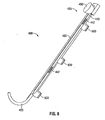
- Figure 8 is a bottom view of the accessory of Figures 6-7 ;
- Figure 9 is another perspective view of the accessory of Figures 5-8 ;
- Figure 10 is a side view of an actuation mechanism according to an embodiment of the present disclosure.
- proximal refers to the end or portion of the clamp closer to the clinician
- distal refers to the end or portion of the clamp farther away from the clinician
- FIGS. 1A - 1C various surgical instruments are shown in accordance with the present disclosure.
- FIG. 1A discloses a linear surgical stapling instrument 10a
- FIG. 1B discloses a surgical stapling instrument 10b having curved jaws 23b
- FIG. 1C discloses a vessel sealing instrument 10c.
- surgical instruments 10a - 10c are collectively referred to as reference number 10.
- linear surgical stapling apparatus 10a includes a handle assembly 12a near a proximal end, an end effector 16a near a distal end and an elongate portion 18a therebetween.
- the end effector 16a may be positioned within a body cavity to engage tissue at a surgical site while handle assembly 12a is manipulatable by a surgeon from outside the body cavity to control the movement and operation of the end effector 16a.
- Elongate portion 18a defines a longitudinal axis A-A.
- End effector 16a includes a cartridge assembly, which houses a plurality of staples arranged in linear rows, and an anvil assembly for forming the staples. At least one of the cartridge assembly and the anvil assembly is movable with respect to the other between an open position wherein the cartridge assembly is substantially spaced from the anvil assembly and an approximated position where the cartridge assembly and the anvil assembly are closer together.
- a pivotable trigger 24a of the handle assembly 12a is movable through an actuation stroke or strokes relative to a stationary grip member 28a to move the cartridge assembly in relation to the anvil assembly between the open position and the approximated position and to eject the staples from the cartridge assembly. Further details of a linear surgical stapling instrument are described in detail in commonly-owned U.S. Patent No.
- the cartridge assembly may include a replaceable cartridge body that houses the staples and staple pushers.
- the end effector 16a may form part of a separate, replaceable loading unit that is attachable to the elongate portion 18a of the stapling apparatus 10a.
- the loading unit includes an elongate body that is configured to attach to the elongate portion 18a through a detent, bayonet or similar attachment feature.
- the end effector 16a may be pivotably attached to the elongate body, in the example of a loading unit, or the elongate portion 18a, in the example of a stapling apparatus where a replaceable cartridge body is used.
- surgical stapling apparatus 10b having curved jaws 23b is shown.
- Surgical stapling apparatus 10b and linear surgical stapling apparatus 10a share various common features, including handle assembly 12b, end effector 16b, and elongate portion 18b, as discussed above.
- the surgical stapling apparatus 10b includes curved jaws 23b. That is, surgical stapling apparatus 10b includes an end effector 16b having a cartridge assembly and an anvil assembly (collectively "jaws 23b"), that are each curved with respect to a longitudinal axis B-B, defined by elongated portion 18b. It is envisioned that curved jaws 23b facilitate performing certain types of surgical procedures.
- the curved jaws are arranged to facilitate use in procedures involving limited access to the targeted surgical site.
- curved jaws 23b as compared to linear jaws (such as the jaws illustrated in Figure 1A ), may help facilitate access to lower pelvis regions, e.g., during lower anterior resection ("LAR").
- LAR anterior resection
- the inclusion of curved jaws 23b may allow increased visualization to a surgical site and may also allow more room for a surgeon to manipulate target tissue or the jaws 23b themselves with his or her hand.
- the cartridge assembly may include a replaceable cartridge body that houses the staples and staple pushers.
- the end effector 16b may form part of a separate, replaceable loading unit that is attachable to the elongate portion 18b of the stapling apparatus 10b.
- the loading unit includes an elongate body that is configured to attach to the elongate portion 18b through a detent, bayonet or similar attachment feature.
- the end effector 16b may be pivotably attached to the elongate body, in the example of a loading unit, or the elongate portion 18b, in the example of a stapling apparatus where a replaceable cartridge body is used.
- Vessel sealing instrument 10c may also embody various aspects of the present disclosure.
- Vessel sealing instrument 10c includes a connector assembly 110c for connection to a source of electrosurgical energy (not shown).
- Vessel sealing instrument 10c includes a handle assembly 12c near a proximal end, an end effector 16c near a distal end and an elongate portion 18c therebetween.
- the end effector 16c may be positioned within a body cavity to engage tissue at a surgical site while handle assembly 12c is manipulatable by a surgeon from outside the body cavity to control the movement and operation of the end effector 16c.
- Handle assembly 12c includes a movable handle 24c, which may be manipulated to open and close the jaws of end effector 16c, and a trigger 25c, which may be manipulated to initiate an electrosurgical current. Further details of a vessel sealing instrument are described in U.S. Patent No. 7,083,618 , which is incorporated herein in its entirety by reference.
- FIGS. 1A-1C An accessory for grasping and/or clamping tissue is shown in FIGS. 1A-1C as attachable clamp 200.
- FIG. 1A illustrates an attachable clamp 200a engaged with linear surgical stapling instrument 10a.
- clamp 200a includes a first linear jaw member 210a and a second linear jaw member 220a.
- FIG. 1B illustrates an attachable clamp 200b engaged with surgical stapling instrument 10b having curved jaws.
- clamp 200b includes a first curved jaw member 210b and a second curved jaw member 220b.
- FIG. 1C illustrates an attachable clamp 200c engaged with vessel sealing instrument 10c.
- clamp 200c includes a first linear jaw member 210c and a second linear jaw member 220c. While FIGS. 1A-1C illustrate one type of an attachable clamp 200, other embodiments of attachable clamps are described herein (as reference numbers 300 and 400) and each embodiment thereof is configured for use with surgical instruments 10.
- the curvature of jaw members 21 0b, 220b of attachable clamp 200b is shown as being approximately equal to, or corresponding to, the curvature of jaws 23b of surgical stapling instrument 10b. While not explicitly shown, it is envisioned that the curvature of jaw members 210b, 220b of attachable clamp 200b is either greater than or less than the curvature of jaws 23b of surgical stapling instrument 10b. It is also envisioned that the curvature of first jaw member 210b is different from the curvature of second jaw member 220b. In the surgical stapling instrument shown in FIG. 1B , jaws 23b have a concave side 290 and a convex side 291.
- jaw members 210b, 220b of attachable clamp 200b are shown having a concave side 211 and a convex side 212.
- other curved shapes can be used for jaws 23b and/or jaw members 210b, 220b.
- attachable clamp 300 includes a first jaw member 310 and a second jaw member 320 that extend distally from an elongated body portion 330.
- Elongated body potion 330 is shown being comprised of a first body half 332 and a second body half 334 (first body half 332 is omitted in FIG. 4 ).
- a plurality of apertures 336 is disposed on each of the first body half 332 and the second body half 334 and may be used (e.g., in combination with appropriate fasteners such as screws, rivets snap-fit connectors, ultrasonic welds, etc.) to facilitate the attachment of each body half 332, 334 to one another and to a frame 340.
- clamp attachment 300 also includes an actuation mechanism 335 including a frame 240, a first cam plate 350, a second cam plate 360, a lower arm 370, an upper arm 380, and a rod 390.
- the lower arm 370 has the first jaw member 310, which may be attached thereto or formed integrally formed therewith.
- the first jaw member 310 desirably includes a tissue contact surface 310a.
- the upper arm 380 has the second jaw member 320, which may be attached thereto or formed integrally formed therewith.
- the second jaw member includes a tissue contact surface 320a.
- Frame 340 is disposed between and is relatively stationary with respect to first body half 332 and second body half 334, and includes vertically disposed slots 342 (two slots are shown) extending therethrough. At least a portion of slots 342 is configured for substantial alignment with at least a portion of corresponding diagonally disposed slots 352 in the first cam plate 350 and diagonally disposed slots 362 in the second cam plate 360. Additionally, at least a portion of slots 342 is configured to substantially align with corresponding apertures 372, 382 in respective lower arm 370 and upper arm 380. As discussed in more detail below, a plurality of pins 395 is used to movably secure first cam plate 350 with respect to frame 340 and lower arm 370 via slots 352, 342, and apertures 372, respectively. Additionally, a plurality of pins 395 (either the same pins or an additional set of pins) is used to movably secure second cam plate 360 with respect to frame 340 and upper arm 380 via slots 362, 342 and apertures 382, respectively.
- the first cam plate 350 includes an aperture 354 disposed adjacent a proximal portion thereof and the second cam plate 360 includes an aperture 364 disposed adjacent a proximal portion thereof. Additionally, the rod 390 includes a pair of apertures 392 disposed adjacent a distal portion thereof A pin 394 extends through apertures 354, 392 and 364 to secure rod 390 to cam plates 350, 360.
- the frame 340 includes a spring plug 344 disposed in mechanical cooperation therewith.
- Spring plug 344 is configured to engage a distal portion of a biasing member 346 (e.g., a helical spring).
- a proximal portion of biasing member 346 is configured to engage the distal portion of rod 390. Accordingly, the biasing member 346 is configured to bias rod 390 proximally with respect to frame 340.
- a user distally pushes a knob 396 of rod 390 against the bias of biasing member 346 to move the jaw members 310 and 320 towards the open position. More particularly, since the rod 390 is pinned to first cam plate 350 and second cam plate 360, distal movement of the rod 390 causes distal translation of cam plates 350 and 360. With initial regard to the first jaw member 310, as the first cam plate 350 translates distally, the pinned relationship between the lower arm 370, the slots 352 (which slope upward as they extend distally), and the vertical slots 342, causes the lower arm 370 to move downward with respect to frame 340.
- the pins 395 travel downwardly and proximally with respect to slots 352.
- the vertical slots 342 limit the motion of the lower arm 370 such that the lower arm 370 only moves downwardly (and not proximally) with respect to frame 340.
- the pinned relationship between the upper arm 380, the slots 362 (which slope downward as they extend distally), and the vertical slots 342, causes the upper arm 380 to move upward with respect to frame 340. That is, when the second cam plate 360 is moved distally, the pins 395 travel upwardly and proximally with respect to slots 362. Moreover, the vertical slots 342 limit the motion of the upper arm 380 such that the upper arm 380 only moves upwardly (and not proximally) with respect to frame 340.
- proximal movement of the knob 396 causes first cam plate 350 and second cam plate 360 to move proximally.
- Proximal movement of first cam plate 350 causes lower arm 370 to move upward with respect to frame 340.
- Proximal movement of second cam plate 360 causes upper arm 380 to move downward with respect to frame 340.
- the jaw members 310, 320 move between a first substantially parallel approximated position ( FIG. 2 ) and a second substantially parallel open position ( FIG. 3 ).
- the jaw members 310, 320 of attachable clamp 300 are biased towards their approximated positions.
- a particular biasing member 346 may be selected (e.g., having a particular spring constant) to provide a desired about of closing force.
- attachable clamp 300 includes structure to releasably lock jaw members 310, 320 in an open position.
- a proximal portion 390a of rod 390 is translatable with respect to a distal portion 390b thereof.
- proximal portion 390a is proximally biased with respect to distal portion 390b via biasing member 390c (e.g., helical spring).
- biasing member 390c e.g., helical spring.
- Proximal portion 390a includes a pin 391 that is configured to ride along a substantially "L"-shaped slot 391a disposed in first body half 332 (as illustrated in FIG. 5 ) or second body half 334.
- proximal portion 390a can be rotated about longitudinal axis "A-A" such that pin 391 moves along a second leg of slot 391 a, thus preventing proximal translation of proximal portion 390a with respect to distal portion 390b, which releasably locks jaw members 310, 320 in the open position.
- first jaw member 310 and the second jaw member 320 is stationary with respect to frame 340.
- lower arm 370 or upper arm 380 would be stationary with respect to frame 340.
- first cam plate 350 or second cam plate 360 could be omitted from the design or could be configured to not include slots 352 or 362.
- the orientation of slots 352 or 362 could be configured to limit or otherwise adjust the relative movement between either first cam plate 350 and lower arm 370, or second cam plate 360 and upper arm 380.
- lower arm 370 and upper arm 380 are illustrated as being curved with respect to the longitudinal axis "A-A," it is envisioned that lower arm 370 and upper arm 380 are co-linear with respect to the longitudinal axis "A-A,” e.g., for use with a surgical instrument having linear jaw member (e.g., linear surgical stapling instrument 10a of FIG. 1A or vessel sealing instrument 10c of FIG. 1C ).
- linear jaw member e.g., linear surgical stapling instrument 10a of FIG. 1A or vessel sealing instrument 10c of FIG. 1C .
- the curvature of the first jaw member and second jaw member of the attachable clamp 300 can be adjusted so that the attachable clamp is disposed on the concave side 290 of the jaws 23b or the convex side 291 of the jaws 23b of the surgical apparatus 10b (see FIG. IB).
- Attachable clamp 400 includes a first jaw member 410, a second jaw member 420, and an actuation mechanism 425 including a body portion 430, a slide member 440, and a knob 450.
- first jaw member 410 and body portion 430 arc stationary with respect to each other (and with respect to elongate portion 18 of surgical instrument 10 when attached thereto) and may be monolithically formed with each other.
- Second jaw member 420 is pivotably disposed with respect to first jaw member 410 and body portion 430 via pivot pin 460 ( FIGS. 6 and 7 ). Pivot pin 460 also extends through a pivot tab 470, as discussed in more detail below.
- the first jaw member 410 has a tissue contact surface 410a that faces a tissue contact surface 420a on the second jaw member 420.
- Pivot tab 470 is disposed adjacent a distal portion of slide member 440 and adjacent a proximal portion of second jaw member 420 ( FIGS. 6 and 7 ). Additionally, pivot tab 470 is fixed to second jaw member 420. It is envisioned that pivot tab 470 is biased via a biasing member 472 (e.g., helical or torsional spring) such that second jaw member 420 is urged towards its open position ( FIG. 7 ).
- a biasing member 472 e.g., helical or torsional spring
- Slide member 440 includes slots 442 therein to accommodate pins 432 of the body portion 430 (see FIG. 9 ), such that slide member 440 is longitudinally translatable with respect to body portion 430.
- a proximal portion of slide member 440 includes a plurality of teeth 444 thereon, which are configured to engage a plurality of teeth 452 of knob 450.
- a user rotates knob 450 to pivotably move second jaw member 420 between its open ( FIG. 7 ) and approximated ( FIG. 6 ) positions. More particularly and with specific reference to FIG. 9 , rotation of knob 450 in the direction of arrow “A” causes second jaw member 420 to move towards its approximated position. Rotation of knob 450 in the direction of arrow “B” causes second jaw member 420 to move towards its open position. Specifically, upon rotation of knob 450 in the direction of arrow "A,” the interaction between teeth 452 of knob 450 and teeth 444 of slide member 440 causes slide member 440 to distally translate such that a distal face 446 ( FIG.
- slide member 440 engages an approximation surface 422 ( FIG. 7 ) of second jaw member 420, thus causing second jaw member 420 to pivot towards first jaw member 410 against the bias of biasing member 472.
- the interaction between teeth 452 of knob 450 and teeth 444 of slide member 440 causes slide member 440 to proximally translate, thus causing second jaw member 420 to pivot away from first jaw member 410. That is, distal face 446 of slide member 440 moves proximally past approximation surface 422 of second jaw member 420, thus allowing biasing member 472 to return second jaw member 420 to its open position.
- Actuation mechanism 480 includes a cam lever 482 that is pivotably engaged with a body portion 484 of the attachable clamp about pivot pin 486, and pivotably engaged with a slide member 488 of the attachable clamp about pivot pin 490. It is envisioned that body portion 484 is mechanically engaged with a first jaw member of an attachable clamp and that slide member 488 is mechanically engaged with a second jaw member of an attachable clamp.
- an actuation mechanism include a locking mechanism for holding the jaw members in the approximated position and having an actuator graspable by a user for releasing the actuation mechanism.
- an actuation mechanism having a ratchet mechanism 492 is shown.
- Ratchet mechanism 492 includes a plurality of teeth 494 disposed on body portion 484 and a plurality of teeth 496 disposed on slide member 488, and is configured to allow controlled and stepped distal advancement of slide member 488 with respect to body portion 484. More particularly, teeth 494 include angled walls 494a and flats or locking member 494b, and teeth 496 include angled walls 496a and flats 496b.
- the interaction between angled walls 494a, 496a and flats 494b, 496b allow movement in the distal direction, but prevent movement in the proximal direction. That is, the flats 494b, 496b maintain slide member 488 in a desired longitudinal position, while restricting the proximal force applied by the compressed tissue.
- cam lever 482 In use, as cam lever 482 is pushed in the direction of arrow "C,” cam lever 482 rotates about pivot pin 486. Pin 490 connects cam lever 482 to slide member 488 such that rotation of cam lever 482 in the direction of arrow “C” distally translates slide member 488 to clamp tissue, for example. Additionally, movement of cam lever 482 in the direction of arrow “D” causes slide member 488 to move proximally with respect to body portion 484, which causes the second jaw member to move towards its open position. Moreover, movement of cam lever 482 in the direction of arrow “D” causes slide member 488 to lift upwardly, thus disengaging teeth 494, 496 and enabling proximal translation of slide member 488 with respect to body portion 484.
- an actuation mechanism including a locking mechanism includes a spring-loaded and shaped recesses, in place of the teeth on slide member 488 and body portion 484 discussed above.
- the spring-loaded detent is mounted in one of the slide member 488 and body portion 484 and recesses are provided on the other of slide member 488 and body portion 484.
- the recesses are shaped so that slide member 488 slides in a distal direction, overcoming the detent, but movement of the cam lever 482 in the proximal direction is required to disengage the detent from the recesses and move the slide member 488 in the proximal direction.
- an actuation mechanism include a locking mechanism for holding the jaw members in the approximated position and having an actuator graspable by a user for releasing the actuation mechanism discussed above can be used with an attachable clamp having jaw members that are shaped and oriented as shown in FIGS. 1 through 9 .
- each attachable clamp 200, 300, 400 is configured to removably engage surgical instrument 10. More particularly, attachable clamp 200 may include one or more attachment members, such as a series of tabs 500, which are configured to clip or slide onto the elongate portion 118 of (and/or a portion of a loading unit configured for use with) the surgical instrument 10. Additionally, it is envisioned that the tabs 500 are removable and/or able to be reoriented (e.g. via screws or the like) to place the tabs 500 on the opposite lateral side of the attachable clamp 200, 300, 400, for example. It is also envisioned that each attachable clamp 200, 3 00, 400 is attachable to the surgical instrument 10 via other suitable means, such as, for example, screws.
- attachable clamp 200, 300,400 When attachable clamp 200, 300,400 is used in combination with surgical instrument 10 to compress tissue, it is envisioned that a user may position jaw members 210 and 220, 310, 320, or 410 and 420 of attachable clamp 200, 300, or 400, respectively, about tissue adjacent the location where the tissue will be joined. After the tissue is clamped, and prior to the joining of tissue, the clinician may perform a washout. It is also envisioned that when the jaw members of the attachable clamp are in the approximated position, the user can manipulate (e.g., slightly move) the jaws 23 of the surgical instrument 10.
- the present disclosure also relates to a method of using attachable clamp 200, 300, 400 during a surgical procedure.
- the method includes providing a surgical instrument 10; attaching an attachable clamp to the surgical instrument, the attachable clamp being configured for attachment to the surgical instrument 10; positioning the jaw members of the surgical instrument 10 adjacent tissue; moving at least one jaw member of the attachable clamp from an open position towards an approximated position to engage body tissue; moving at least one of the jaw members of the surgical instrument with respect to the other from an open position towards an approximated position to engage body tissue; and actuating the jaw members of the surgical instrument to join tissue.
- the method may also include the step of cleansing tissue (e.g., performing a washout) between the steps of moving at least one of the jaw members of the surgical instrument with respect to the other from an open position towards an approximated position to engage body tissue and actuating the jaw members of the surgical instrument to join tissue.
- cleansing tissue e.g., performing a washout
- the rectum may be washed out while the clamp jaw members are clamped onto the tissue.
- the surgical stapling instrument or other instrument for joining tissue is applied to the section of tissue that has been washed out.
Abstract
Description
- The present disclosure relates generally to instruments for surgically joining tissue and, more specifically, to an accessory for grasping and/or clamping tissue, for use with a surgical instrument for joining and/or cutting tissue.
- Various types of surgical instruments used to surgically join tissue are known in the art, and are commonly used, for example, for closure of tissue or organs in transection, resection, anastomoses, for occlusion of organs in thoracic and abdominal procedures, and for electrosurgically fusing or sealing tissue.
- One example of such a surgical instrument is a surgical stapling instrument, which may include an anvil assembly, a cartridge assembly for supporting an array of surgical staples, an approximation mechanism for approximating the cartridge and anvil assemblies, and a firing mechanism for ejecting the surgical staples from the cartridge assembly.
- Using a surgical stapling instrument, it is common for a surgeon to approximate the anvil and cartridge members. Next, the surgeon can fire the instrument to emplace staples in tissue. Additionally, the surgeon may use the same instrument or a separate instrument to cut the tissue adjacent or between the row(s) of staples.
- Other examples of a surgical instrument of the present disclosure include electrosurgical (e.g., monopolar and bipolar) forceps. Electrosurgical forceps utilize both mechanical clamping action and electrical energy to affect hemostasis by heating the tissue and blood vessels to coagulate, cauterize and/or seal tissue.
- In certain procedures, some surgeons wash out the inside of an organ prior to cutting and stapling (or otherwise joining) the tissue. A clamp may be used to define an area to be washed out.
- The present disclosure relates to an attachable clamp for use with a surgical instrument. The attachable clamp comprises a body portion, a first jaw member, a second jaw member and an actuation mechanism. The body portion defines a longitudinal axis and has attachment members configured to attach to an elongate portion of a surgical instrument. Each of the first jaw member and second jaw member extends distally from the body portion. The actuation mechanism is disposed in mechanical cooperation with at least one of the first jaw member and the second jaw member. Actuation of the actuation mechanism moves at least one of the first and second jaw members between an approximated position and an open position with respect to the other jaw member.
- The attachable clamp has attachment members configured to removably attach to the body portion and to removably attach to the elongate portion of the surgical instrument, in certain embodiments.
- In certain embodiments, the first jaw member and the second jaw member may correspond to jaws of the surgical instrument in shape and orientation.
- Each of the first jaw member and the second jaw member may be curved with respect to the longitudinal axis and include a concave and a convex side. The jaws of the surgical instrument may be curved, and they may have a convex side and a concave side. In certain embodiments, the convex side of the first jaw member and the second jaw member is disposed adjacent the jaws of the surgical instrument, and in other embodiments, the concave side of the first jaw member and the second jaw member is disposed adjacent the jaws of the surgical instrument.
- The actuation mechanism can include a first cam plate disposed in mechanical cooperation with the first jaw member and disposed in mechanical cooperation with a rod. Translation of the rod causes the first jaw member to move upwardly. The translation of the rod in a first direction causes the first jaw member to move upwardly toward the open position. The rod is desirably biased toward a position so that the first jaw member tends to move toward the approximated position.
- The actuation mechanism, in certain embodiments, further comprises a second cam plate disposed in mechanical cooperation with the second jaw member and disposed in mechanical cooperation with the rod. Translation of the rod causes the second jaw member to move downwardly. The translation of the rod in a first direction causes the second jaw member to move downwardly toward the open position.
- In certain embodiments, the first jaw member and second jaw member are substantially parallel to one another when the jaw members are in the open and approximated positions. The first jaw member may be stationary with respect to the body portion.
- The actuation mechanism may include a knob and a slide member, wherein rotation of the knob causes the second jaw member to pivot towards the first jaw member. The knob can include a plurality of teeth that are configured to engage a plurality of teeth on the slide member.
- In another aspect, the present disclosure also relates to a method of surgically joining tissue. The method comprises the step of providing a surgical instrument including a handle portion, an endoscopic portion and a pair of jaw members. The endoscopic portion extends distally from the handle portion. The pair of jaw members is disposed adjacent a distal end of the endoscopic portion. At least one of the jaw members is movable with respect to the other between an open position and an approximated position for engaging body tissue therebetween. The method also comprises the step of providing an attachable clamp configured to be attached to the surgical instrument. The attachable clamp includes a body portion, a first jaw member, a second jaw member, and an actuation mechanism. The body portion defines a longitudinal axis. The first and second jaw members extend distally from the body portion. The actuation mechanism is disposed in mechanical cooperation with at least one of the first jaw member and the second jaw member. At least one jaw member of the attachable clamp is independently movable with respect to the jaw members of the surgical instrument. The method also includes the steps of moving at least one jaw member of the attachable clamp from an open position towards an approximated position to engage body tissue, moving at least one of the jaw members of the surgical instrument with respect to the other from an open position towards an approximated position to engage body tissue, and actuating the jaw members of the surgical instrument to join tissue.
- In a further aspect of the present disclosure, an attachable clamp for use with a surgical instrument comprises:a body portion defining a longitudinal axis and having attachment members configured to attach to a surgical instrument; a first jaw member extending distally from the body portion; and a second jaw member extending distally from the body portion. The attachable clamp further includes an actuation mechanism disposed in mechanical cooperation with at least one of the first jaw member and the second jaw member, wherein actuation of the actuation mechanism moves at least one of the first and second jaw members between an approximated position for clamping tissue and an open position with respect to the other jaw member. The actuation mechanism holds the jaw members in the approximated position and has an actuator graspable by a user for releasing the actuation mechanism.
- In certain embodiments, the attachable clamp has attachment members that are configured to removably attach to the elongate portion of the surgical instrument. The first jaw member and second jaw member of the attachable clamp desirably correspond to jaws of the surgical instrument in shape and orientation.
- The actuation mechanism may include a first cam plate disposed in mechanical cooperation with the first jaw member and disposed in mechanical cooperation with a rod, and wherein translation of the rod causes the first jaw member to move upwardly toward the open position. The actuation mechanism desirably biases the first jaw member and the second jaw member toward the approximated position.
- The first jaw member and the second jaw member are substantially parallel to one another when the jaw members are in the open and approximated positions, in certain embodiments. The first jaw member may be stationary with respect to the body potion.
- The actuation mechanism includes a slide member having teeth, in certain embodiments of the present disclosure. The actuation mechanism may includes locking member that engages the teeth of the slide member. The teeth are configured to allow the slide member to slide with respect to the locking member in a first direction and configured to engage the locking member to move the slide member in a second direction.
- In certain embodiments, the actuation mechanism includes a detent configured to allow the slide member to slide with respect to the detent in a first direction and configured to engage the slide member to move the slide member in a second direction.
- Various embodiments of the presently disclosed surgical instrument are disclosed herein with reference to the drawings, wherein:
-
Figure 1A is a perspective view of a linear surgical stapling instrument including an attachable clamp in accordance with the present disclosure; -
Figure 1B is a perspective view of an surgical stapling instrument having curved jaw members and including an attachable clamp in accordance with the present disclosure; -
Figure 1C is a perspective view of a vessel sealing instrument including an attachable clamp in accordance with the present disclosure; -
Figures 2-4 are perspective views of an accessory according to an embodiment of the present disclosure, shown at various stages of operation, for use with the surgical instruments ofFigure 1A and1B ; -
Figure 5 is an exploded views of the accessory according to the embodiment shown inFigures 2-4 , illustrating a closing mechanism for use with a clamp; -
Figure 6 is a perspective view of an accessory according to a further embodiment of the present disclosure, illustrating a closing mechanism for use with a clamp; -
Figure 7 is a perspective view of the accessory ofFigure 6 ; -
Figure 8 is a bottom view of the accessory ofFigures 6-7 ; -
Figure 9 is another perspective view of the accessory ofFigures 5-8 ; and -
Figure 10 is a side view of an actuation mechanism according to an embodiment of the present disclosure. - Embodiments of the presently disclosed clamp for use with a surgical instrument are described in detail with reference to the drawings, wherein like reference numerals designate corresponding elements in each of the several views. In the description that follows, the term "proximal" refers to the end or portion of the clamp closer to the clinician, whereas the term "distal" refers to the end or portion of the clamp farther away from the clinician.
- Referring initially to
FIGS. 1A - 1C , various surgical instruments are shown in accordance with the present disclosure. In particular,FIG. 1A discloses a linearsurgical stapling instrument 10a,FIG. 1B discloses asurgical stapling instrument 10b havingcurved jaws 23b, andFIG. 1C discloses avessel sealing instrument 10c. As discussed herein,surgical instruments 10a - 10c are collectively referred to as reference number 10. - With reference to
FIG. 1A , linearsurgical stapling apparatus 10a includes ahandle assembly 12a near a proximal end, anend effector 16a near a distal end and anelongate portion 18a therebetween. Theend effector 16a may be positioned within a body cavity to engage tissue at a surgical site whilehandle assembly 12a is manipulatable by a surgeon from outside the body cavity to control the movement and operation of theend effector 16a.Elongate portion 18a defines a longitudinal axis A-A. -
End effector 16a includes a cartridge assembly, which houses a plurality of staples arranged in linear rows, and an anvil assembly for forming the staples. At least one of the cartridge assembly and the anvil assembly is movable with respect to the other between an open position wherein the cartridge assembly is substantially spaced from the anvil assembly and an approximated position where the cartridge assembly and the anvil assembly are closer together. Apivotable trigger 24a of thehandle assembly 12a is movable through an actuation stroke or strokes relative to astationary grip member 28a to move the cartridge assembly in relation to the anvil assembly between the open position and the approximated position and to eject the staples from the cartridge assembly. Further details of a linear surgical stapling instrument are described in detail in commonly-ownedU.S. Patent No. 6,953,139 to Milliman et al. , the entire contents of which are hereby incorporated by reference herein. The cartridge assembly may include a replaceable cartridge body that houses the staples and staple pushers. Alternatively, theend effector 16a may form part of a separate, replaceable loading unit that is attachable to theelongate portion 18a of thestapling apparatus 10a. The loading unit includes an elongate body that is configured to attach to theelongate portion 18a through a detent, bayonet or similar attachment feature. Theend effector 16a may be pivotably attached to the elongate body, in the example of a loading unit, or theelongate portion 18a, in the example of a stapling apparatus where a replaceable cartridge body is used. - With reference to
FIG. 1B ,surgical stapling apparatus 10b havingcurved jaws 23b is shown.Surgical stapling apparatus 10b and linearsurgical stapling apparatus 10a share various common features, includinghandle assembly 12b,end effector 16b, andelongate portion 18b, as discussed above. Thesurgical stapling apparatus 10b includescurved jaws 23b. That is,surgical stapling apparatus 10b includes anend effector 16b having a cartridge assembly and an anvil assembly (collectively "jaws 23b"), that are each curved with respect to a longitudinal axis B-B, defined byelongated portion 18b. It is envisioned thatcurved jaws 23b facilitate performing certain types of surgical procedures. The curved jaws are arranged to facilitate use in procedures involving limited access to the targeted surgical site. For example,curved jaws 23b, as compared to linear jaws (such as the jaws illustrated inFigure 1A ), may help facilitate access to lower pelvis regions, e.g., during lower anterior resection ("LAR"). Additionally, the inclusion ofcurved jaws 23b may allow increased visualization to a surgical site and may also allow more room for a surgeon to manipulate target tissue or thejaws 23b themselves with his or her hand. The cartridge assembly may include a replaceable cartridge body that houses the staples and staple pushers. Alternatively, theend effector 16b may form part of a separate, replaceable loading unit that is attachable to theelongate portion 18b of thestapling apparatus 10b. The loading unit includes an elongate body that is configured to attach to theelongate portion 18b through a detent, bayonet or similar attachment feature. Theend effector 16b may be pivotably attached to the elongate body, in the example of a loading unit, or theelongate portion 18b, in the example of a stapling apparatus where a replaceable cartridge body is used. - Referring now to
FIG. 1C , avessel sealing instrument 10c may also embody various aspects of the present disclosure.Vessel sealing instrument 10c includes aconnector assembly 110c for connection to a source of electrosurgical energy (not shown).Vessel sealing instrument 10c includes ahandle assembly 12c near a proximal end, anend effector 16c near a distal end and anelongate portion 18c therebetween. Theend effector 16c may be positioned within a body cavity to engage tissue at a surgical site whilehandle assembly 12c is manipulatable by a surgeon from outside the body cavity to control the movement and operation of theend effector 16c. Handleassembly 12c includes amovable handle 24c, which may be manipulated to open and close the jaws ofend effector 16c, and atrigger 25c, which may be manipulated to initiate an electrosurgical current. Further details of a vessel sealing instrument are described inU.S. Patent No. 7,083,618 , which is incorporated herein in its entirety by reference. - An accessory for grasping and/or clamping tissue is shown in
FIGS. 1A-1C as attachable clamp 200.FIG. 1A illustrates anattachable clamp 200a engaged with linearsurgical stapling instrument 10a. In this embodiment,clamp 200a includes a firstlinear jaw member 210a and a secondlinear jaw member 220a.FIG. 1B illustrates an attachable clamp 200b engaged withsurgical stapling instrument 10b having curved jaws. In this embodiment, clamp 200b includes a firstcurved jaw member 210b and a secondcurved jaw member 220b.FIG. 1C illustrates anattachable clamp 200c engaged withvessel sealing instrument 10c. In this embodiment,clamp 200c includes a firstlinear jaw member 210c and a secondlinear jaw member 220c. WhileFIGS. 1A-1C illustrate one type of an attachable clamp 200, other embodiments of attachable clamps are described herein (asreference numbers 300 and 400) and each embodiment thereof is configured for use with surgical instruments 10. - Referring back to
FIG. 1B , the curvature of jaw members 21 0b, 220b of attachable clamp 200b is shown as being approximately equal to, or corresponding to, the curvature ofjaws 23b ofsurgical stapling instrument 10b. While not explicitly shown, it is envisioned that the curvature ofjaw members jaws 23b ofsurgical stapling instrument 10b. It is also envisioned that the curvature offirst jaw member 210b is different from the curvature ofsecond jaw member 220b. In the surgical stapling instrument shown inFIG. 1B ,jaws 23b have aconcave side 290 and aconvex side 291. Additionally,jaw members concave side 211 and a convex side 212. However, other curved shapes can be used forjaws 23b and/orjaw members - Referring now to
FIGS. 2-5 , various details of an attachable clamp in accordance with an embodiment of the present disclosure are illustrated. In this embodiment, attachable clamp is generally referred to asreference number 300.Attachable clamp 300 includes afirst jaw member 310 and asecond jaw member 320 that extend distally from anelongated body portion 330.Elongated body potion 330 is shown being comprised of afirst body half 332 and a second body half 334 (first body half 332 is omitted inFIG. 4 ). A plurality ofapertures 336 is disposed on each of thefirst body half 332 and thesecond body half 334 and may be used (e.g., in combination with appropriate fasteners such as screws, rivets snap-fit connectors, ultrasonic welds, etc.) to facilitate the attachment of eachbody half frame 340. - With reference to the assembly view illustrated in
FIG. 5 ,clamp attachment 300 also includes anactuation mechanism 335 including a frame 240, afirst cam plate 350, asecond cam plate 360, alower arm 370, anupper arm 380, and arod 390. Thelower arm 370 has thefirst jaw member 310, which may be attached thereto or formed integrally formed therewith. Thefirst jaw member 310 desirably includes a tissue contact surface 310a. Theupper arm 380 has thesecond jaw member 320, which may be attached thereto or formed integrally formed therewith. The second jaw member includes a tissue contact surface 320a.Frame 340 is disposed between and is relatively stationary with respect tofirst body half 332 andsecond body half 334, and includes vertically disposed slots 342 (two slots are shown) extending therethrough. At least a portion ofslots 342 is configured for substantial alignment with at least a portion of corresponding diagonally disposedslots 352 in thefirst cam plate 350 and diagonally disposedslots 362 in thesecond cam plate 360. Additionally, at least a portion ofslots 342 is configured to substantially align withcorresponding apertures lower arm 370 andupper arm 380. As discussed in more detail below, a plurality ofpins 395 is used to movably securefirst cam plate 350 with respect to frame 340 andlower arm 370 viaslots apertures 372, respectively. Additionally, a plurality of pins 395 (either the same pins or an additional set of pins) is used to movably securesecond cam plate 360 with respect to frame 340 andupper arm 380 viaslots apertures 382, respectively. - The
first cam plate 350 includes anaperture 354 disposed adjacent a proximal portion thereof and thesecond cam plate 360 includes anaperture 364 disposed adjacent a proximal portion thereof. Additionally, therod 390 includes a pair ofapertures 392 disposed adjacent a distal portion thereof Apin 394 extends throughapertures rod 390 tocam plates - With continued reference to
FIG. 5 , theframe 340 includes aspring plug 344 disposed in mechanical cooperation therewith.Spring plug 344 is configured to engage a distal portion of a biasing member 346 (e.g., a helical spring). A proximal portion of biasingmember 346 is configured to engage the distal portion ofrod 390. Accordingly, the biasingmember 346 is configured to biasrod 390 proximally with respect toframe 340. - In use, to operate
attachable clamp 300, a user distally pushes aknob 396 ofrod 390 against the bias of biasingmember 346 to move thejaw members rod 390 is pinned tofirst cam plate 350 andsecond cam plate 360, distal movement of therod 390 causes distal translation ofcam plates first jaw member 310, as thefirst cam plate 350 translates distally, the pinned relationship between thelower arm 370, the slots 352 (which slope upward as they extend distally), and thevertical slots 342, causes thelower arm 370 to move downward with respect toframe 340. That is, when thefirst cam plate 350 is moved distally, thepins 395 travel downwardly and proximally with respect toslots 352. Moreover, thevertical slots 342 limit the motion of thelower arm 370 such that thelower arm 370 only moves downwardly (and not proximally) with respect toframe 340. - Correspondingly, with regard to the
second jaw member 320, as thesecond cam plate 360 translates distally, the pinned relationship between theupper arm 380, the slots 362 (which slope downward as they extend distally), and thevertical slots 342, causes theupper arm 380 to move upward with respect toframe 340. That is, when thesecond cam plate 360 is moved distally, thepins 395 travel upwardly and proximally with respect toslots 362. Moreover, thevertical slots 342 limit the motion of theupper arm 380 such that theupper arm 380 only moves upwardly (and not proximally) with respect toframe 340. - As can be appreciated with reference to
FIGS. 2-5 and with reference to the discussion hereinabove, proximal movement of the knob 396 (i.e., in the direction provided by the bias of biasing member 346) causesfirst cam plate 350 andsecond cam plate 360 to move proximally. Proximal movement offirst cam plate 350 causeslower arm 370 to move upward with respect toframe 340. Proximal movement ofsecond cam plate 360 causesupper arm 380 to move downward with respect toframe 340. Thus, thejaw members FIG. 2 ) and a second substantially parallel open position (FIG. 3 ). Additionally, as described above, thejaw members attachable clamp 300 are biased towards their approximated positions. As can be appreciated, aparticular biasing member 346 may be selected (e.g., having a particular spring constant) to provide a desired about of closing force. - It is also envisioned that
attachable clamp 300 includes structure to releasablylock jaw members rod 390 is translatable with respect to a distal portion 390b thereof. Additionally, proximal portion 390a is proximally biased with respect to distal portion 390b via biasing member 390c (e.g., helical spring). SeeFigure 5 . Proximal portion 390a includes apin 391 that is configured to ride along a substantially "L"-shapedslot 391a disposed in first body half 332 (as illustrated inFIG. 5 ) orsecond body half 334. Oncepin 391 is fully translated distally with respect to slot 391a (i.e., pin 391 moves along a first leg ofslot 391a), proximal portion 390a can be rotated about longitudinal axis "A-A" such thatpin 391 moves along a second leg ofslot 391 a, thus preventing proximal translation of proximal portion 390a with respect to distal portion 390b, which releasably locksjaw members - While not explicitly illustrated, it is envisioned that one of the
first jaw member 310 and thesecond jaw member 320 is stationary with respect toframe 340. In such an embodiment,lower arm 370 orupper arm 380 would be stationary with respect toframe 340. That is,first cam plate 350 orsecond cam plate 360 could be omitted from the design or could be configured to not includeslots slots first cam plate 350 andlower arm 370, orsecond cam plate 360 andupper arm 380. Additionally, whilelower arm 370 andupper arm 380 are illustrated as being curved with respect to the longitudinal axis "A-A," it is envisioned thatlower arm 370 andupper arm 380 are co-linear with respect to the longitudinal axis "A-A," e.g., for use with a surgical instrument having linear jaw member (e.g., linearsurgical stapling instrument 10a ofFIG. 1A orvessel sealing instrument 10c ofFIG. 1C ). - It is contemplated that the curvature of the first jaw member and second jaw member of the
attachable clamp 300 can be adjusted so that the attachable clamp is disposed on theconcave side 290 of thejaws 23b or theconvex side 291 of thejaws 23b of thesurgical apparatus 10b (see FIG. IB). - With reference to
FIGS. 6-9 , another embodiment of an accessory for grasping and/or clamping tissue is shown and is depicted asattachable clamp 400.Attachable clamp 400 includes afirst jaw member 410, asecond jaw member 420, and anactuation mechanism 425 including abody portion 430, aslide member 440, and aknob 450. In this embodiment,first jaw member 410 andbody portion 430 arc stationary with respect to each other (and with respect to elongate portion 18 of surgical instrument 10 when attached thereto) and may be monolithically formed with each other.Second jaw member 420 is pivotably disposed with respect tofirst jaw member 410 andbody portion 430 via pivot pin 460 (FIGS. 6 and7 ).Pivot pin 460 also extends through apivot tab 470, as discussed in more detail below. Thefirst jaw member 410 has a tissue contact surface 410a that faces a tissue contact surface 420a on thesecond jaw member 420. -
Pivot tab 470 is disposed adjacent a distal portion ofslide member 440 and adjacent a proximal portion of second jaw member 420 (FIGS. 6 and7 ). Additionally,pivot tab 470 is fixed tosecond jaw member 420. It is envisioned thatpivot tab 470 is biased via a biasing member 472 (e.g., helical or torsional spring) such thatsecond jaw member 420 is urged towards its open position (FIG. 7 ). -
Slide member 440 includesslots 442 therein to accommodatepins 432 of the body portion 430 (seeFIG. 9 ), such thatslide member 440 is longitudinally translatable with respect tobody portion 430. With particular reference toFIG. 9 , a proximal portion ofslide member 440 includes a plurality ofteeth 444 thereon, which are configured to engage a plurality ofteeth 452 ofknob 450. - In use, to operate
attachable clamp 400, a user rotatesknob 450 to pivotably movesecond jaw member 420 between its open (FIG. 7 ) and approximated (FIG. 6 ) positions. More particularly and with specific reference toFIG. 9 , rotation ofknob 450 in the direction of arrow "A" causessecond jaw member 420 to move towards its approximated position. Rotation ofknob 450 in the direction of arrow "B" causessecond jaw member 420 to move towards its open position. Specifically, upon rotation ofknob 450 in the direction of arrow "A," the interaction betweenteeth 452 ofknob 450 andteeth 444 ofslide member 440 causesslide member 440 to distally translate such that a distal face 446 (FIG. 6 ) ofslide member 440 engages an approximation surface 422 (FIG. 7 ) ofsecond jaw member 420, thus causingsecond jaw member 420 to pivot towardsfirst jaw member 410 against the bias of biasing member 472. Correspondingly, upon rotation ofknob 450 in the direction of arrow "B," the interaction betweenteeth 452 ofknob 450 andteeth 444 ofslide member 440 causesslide member 440 to proximally translate, thus causingsecond jaw member 420 to pivot away fromfirst jaw member 410. That is,distal face 446 ofslide member 440 moves proximallypast approximation surface 422 ofsecond jaw member 420, thus allowing biasing member 472 to returnsecond jaw member 420 to its open position. - With reference to
FIG. 10 , another embodiment of an actuation mechanism for use with an accessory of the present disclosure is shown and is depicted as reference number 480. Actuation mechanism 480 includes acam lever 482 that is pivotably engaged with abody portion 484 of the attachable clamp aboutpivot pin 486, and pivotably engaged with aslide member 488 of the attachable clamp aboutpivot pin 490. It is envisioned thatbody portion 484 is mechanically engaged with a first jaw member of an attachable clamp and thatslide member 488 is mechanically engaged with a second jaw member of an attachable clamp. - Certain embodiments of an actuation mechanism include a locking mechanism for holding the jaw members in the approximated position and having an actuator graspable by a user for releasing the actuation mechanism. For example, in
FIG. 10 , an actuation mechanism having a ratchet mechanism 492 is shown. Ratchet mechanism 492 includes a plurality ofteeth 494 disposed onbody portion 484 and a plurality ofteeth 496 disposed onslide member 488, and is configured to allow controlled and stepped distal advancement ofslide member 488 with respect tobody portion 484. More particularly,teeth 494 include angled walls 494a and flats or locking member 494b, andteeth 496 include angled walls 496a and flats 496b. As can be appreciated, the interaction between angled walls 494a, 496a and flats 494b, 496b allow movement in the distal direction, but prevent movement in the proximal direction. That is, the flats 494b, 496b maintainslide member 488 in a desired longitudinal position, while restricting the proximal force applied by the compressed tissue. - In use, as
cam lever 482 is pushed in the direction of arrow "C,"cam lever 482 rotates aboutpivot pin 486.Pin 490 connectscam lever 482 to slidemember 488 such that rotation ofcam lever 482 in the direction of arrow "C" distally translatesslide member 488 to clamp tissue, for example. Additionally, movement ofcam lever 482 in the direction of arrow "D" causesslide member 488 to move proximally with respect tobody portion 484, which causes the second jaw member to move towards its open position. Moreover, movement ofcam lever 482 in the direction of arrow "D" causesslide member 488 to lift upwardly, thus disengagingteeth slide member 488 with respect tobody portion 484. - Another embodiment of an actuation mechanism including a locking mechanism includes a spring-loaded and shaped recesses, in place of the teeth on
slide member 488 andbody portion 484 discussed above. The spring-loaded detent is mounted in one of theslide member 488 andbody portion 484 and recesses are provided on the other ofslide member 488 andbody portion 484. The recesses are shaped so thatslide member 488 slides in a distal direction, overcoming the detent, but movement of thecam lever 482 in the proximal direction is required to disengage the detent from the recesses and move theslide member 488 in the proximal direction. - The embodiments of an actuation mechanism include a locking mechanism for holding the jaw members in the approximated position and having an actuator graspable by a user for releasing the actuation mechanism discussed above can be used with an attachable clamp having jaw members that are shaped and oriented as shown in
FIGS. 1 through 9 . - In each of the illustrated embodiments, each
attachable clamp tabs 500, which are configured to clip or slide onto the elongate portion 118 of (and/or a portion of a loading unit configured for use with) the surgical instrument 10. Additionally, it is envisioned that thetabs 500 are removable and/or able to be reoriented (e.g. via screws or the like) to place thetabs 500 on the opposite lateral side of theattachable clamp - When attachable clamp 200, 300,400 is used in combination with surgical instrument 10 to compress tissue, it is envisioned that a user may position
jaw members attachable clamp - The present disclosure also relates to a method of using
attachable clamp - While the above description contains many specifics, these specifics should not be construed as limitations on the scope of the present disclosure, but merely as illustrations of various embodiments thereof. Therefore, the above description should not be construed as limiting, but merely as exemplifications of various embodiments. Those skilled in the art will envision other modifications within the scope and spirit of the disclosure.
Claims (16)
- An attachable clamp for use with a surgical instrument, the attachable clamp comprising:a body portion defining a longitudinal axis and having attachment members configured to attach to an elongate portion of a surgical instrument;a first jaw member extending distally from the body portion;a second jaw member extending distally from the body portion; andan actuation mechanism disposed in mechanical cooperation with at least one of the first jaw member and the second jaw member, wherein actuation of the actuation mechanism moves at least one of the first and second jaw members between an approximated position and an open position with respect to the other jaw member.
- The attachable clamp of claim 1, wherein the attachment members are configured to removably attach to the body portion and to removably attach to the elongate portion of the surgical instrument.
- The attachable clamp of claim 1 or claim 2, wherein the first jaw member and second jaw member correspond to jaws of the surgical instrument in shape and orientation.
- The attachable clamp of claim 3, wherein each of the first jaw member and the second jaw member are curved with respect to the longitudinal axis.
- The attachable clamp of claim 4, wherein each of the first jaw member and the second jaw member includes a concave side and a convex side.
- The attachable clamp of claim 5, wherein the concave sides of the first jaw member and the second jaw member are disposed adjacent the jaws of the surgical instrument.
- The attachable clamp of claim 5, wherein the convex sides of the first jaw member and the second jaw member are disposed adjacent the jaws of the surgical instrument.
- The attachable clamp of any preceding claim, wherein the actuation mechanism includes a first cam plate disposed in mechanical cooperation with the first jaw member and disposed in mechanical cooperation with a rod, and wherein translation of the rod causes the first jaw member to move upwardly.
- The attachable clamp of claim 8, wherein the translation of the rod in a first direction causes the first jaw member to move upwardly toward the open position.
- The attachable clamp of claim 9, wherein the rod is biased toward a position so that the first jaw member tends to move toward the approximated position.
- The attachable clamp of claim 8, wherein the actuation mechanism further comprises a second cam plate disposed in mechanical cooperation with the second jaw member and disposed in mechanical cooperation with the rod, wherein translation of the rod causes the second jaw member to move downwardly.
- The attachable clamp of claim 11, wherein the translation of the rod in a first direction causes the second jaw member to move downwardly toward the open position.
- The attachable clamp of claim 1, wherein the first jaw member and the second jaw member are substantially parallel to one another when the jaw members are in the open and approximated positions.
- The attachable clamp of claim 1, wherein the first jaw member is stationary with respect to the body potion.
- The attachable clamp of claim 1, wherein the actuation mechanism includes a knob and a slide member, and wherein rotation of the knob causes the second jaw member to pivot towards the first jaw member.
- The attachable clamp of claim 15, wherein the knob includes a plurality of teeth which are configured to engage a plurality of teeth of the slide member.
Priority Applications (2)
| Application Number | Priority Date | Filing Date | Title |
|---|---|---|---|
| EP11193444.4A EP2430988B1 (en) | 2009-05-18 | 2010-05-17 | Attachable clamp for use with surgical instruments |
| EP11005851.8A EP2380504B1 (en) | 2009-05-18 | 2010-05-17 | Attachable clamp for use with surgical instruments |
Applications Claiming Priority (1)
| Application Number | Priority Date | Filing Date | Title |
|---|---|---|---|
| US12/467,324 US9023069B2 (en) | 2009-05-18 | 2009-05-18 | Attachable clamp for use with surgical instruments |
Related Child Applications (2)
| Application Number | Title | Priority Date | Filing Date |
|---|---|---|---|
| EP11005851.8 Division-Into | 2011-07-18 | ||
| EP11193444.4 Division-Into | 2011-12-14 |
Publications (2)
| Publication Number | Publication Date |
|---|---|
| EP2253279A1 true EP2253279A1 (en) | 2010-11-24 |
| EP2253279B1 EP2253279B1 (en) | 2012-07-11 |
Family
ID=42537436
Family Applications (3)
| Application Number | Title | Priority Date | Filing Date |
|---|---|---|---|
| EP11005851.8A Not-in-force EP2380504B1 (en) | 2009-05-18 | 2010-05-17 | Attachable clamp for use with surgical instruments |
| EP10250934A Not-in-force EP2253279B1 (en) | 2009-05-18 | 2010-05-17 | Attachable clamp for use with surgical instruments |
| EP11193444.4A Not-in-force EP2430988B1 (en) | 2009-05-18 | 2010-05-17 | Attachable clamp for use with surgical instruments |
Family Applications Before (1)
| Application Number | Title | Priority Date | Filing Date |
|---|---|---|---|
| EP11005851.8A Not-in-force EP2380504B1 (en) | 2009-05-18 | 2010-05-17 | Attachable clamp for use with surgical instruments |
Family Applications After (1)
| Application Number | Title | Priority Date | Filing Date |
|---|---|---|---|
| EP11193444.4A Not-in-force EP2430988B1 (en) | 2009-05-18 | 2010-05-17 | Attachable clamp for use with surgical instruments |
Country Status (7)
| Country | Link |
|---|---|
| US (3) | US9023069B2 (en) |
| EP (3) | EP2380504B1 (en) |
| JP (2) | JP5543266B2 (en) |
| CN (1) | CN101889888B (en) |
| AU (1) | AU2010201448B2 (en) |
| CA (1) | CA2701065A1 (en) |
| ES (1) | ES2424018T3 (en) |
Cited By (4)
| Publication number | Priority date | Publication date | Assignee | Title |
|---|---|---|---|---|
| US9375218B2 (en) | 2006-05-03 | 2016-06-28 | Datascope Corp. | Systems and methods of tissue closure |
| EP3103401A1 (en) * | 2015-06-08 | 2016-12-14 | Universita Degli Studi Di Perugia | Surgical instrument for colon-rectum operations |
| US10485545B2 (en) | 2013-11-19 | 2019-11-26 | Datascope Corp. | Fastener applicator with interlock |
| US11653928B2 (en) | 2018-03-28 | 2023-05-23 | Datascope Corp. | Device for atrial appendage exclusion |
Families Citing this family (375)
| Publication number | Priority date | Publication date | Assignee | Title |
|---|---|---|---|---|
| US20070084897A1 (en) | 2003-05-20 | 2007-04-19 | Shelton Frederick E Iv | Articulating surgical stapling instrument incorporating a two-piece e-beam firing mechanism |
| US9060770B2 (en) | 2003-05-20 | 2015-06-23 | Ethicon Endo-Surgery, Inc. | Robotically-driven surgical instrument with E-beam driver |
| US8215531B2 (en) | 2004-07-28 | 2012-07-10 | Ethicon Endo-Surgery, Inc. | Surgical stapling instrument having a medical substance dispenser |
| US11896225B2 (en) | 2004-07-28 | 2024-02-13 | Cilag Gmbh International | Staple cartridge comprising a pan |
| US11246590B2 (en) | 2005-08-31 | 2022-02-15 | Cilag Gmbh International | Staple cartridge including staple drivers having different unfired heights |
| US10159482B2 (en) | 2005-08-31 | 2018-12-25 | Ethicon Llc | Fastener cartridge assembly comprising a fixed anvil and different staple heights |
| US9237891B2 (en) | 2005-08-31 | 2016-01-19 | Ethicon Endo-Surgery, Inc. | Robotically-controlled surgical stapling devices that produce formed staples having different lengths |
| US7669746B2 (en) | 2005-08-31 | 2010-03-02 | Ethicon Endo-Surgery, Inc. | Staple cartridges for forming staples having differing formed staple heights |
| US7934630B2 (en) | 2005-08-31 | 2011-05-03 | Ethicon Endo-Surgery, Inc. | Staple cartridges for forming staples having differing formed staple heights |
| US11484312B2 (en) | 2005-08-31 | 2022-11-01 | Cilag Gmbh International | Staple cartridge comprising a staple driver arrangement |
| US20070106317A1 (en) | 2005-11-09 | 2007-05-10 | Shelton Frederick E Iv | Hydraulically and electrically actuated articulation joints for surgical instruments |
| US20110290856A1 (en) | 2006-01-31 | 2011-12-01 | Ethicon Endo-Surgery, Inc. | Robotically-controlled surgical instrument with force-feedback capabilities |
| US11278279B2 (en) | 2006-01-31 | 2022-03-22 | Cilag Gmbh International | Surgical instrument assembly |
| US7753904B2 (en) | 2006-01-31 | 2010-07-13 | Ethicon Endo-Surgery, Inc. | Endoscopic surgical instrument with a handle that can articulate with respect to the shaft |
| US8186555B2 (en) | 2006-01-31 | 2012-05-29 | Ethicon Endo-Surgery, Inc. | Motor-driven surgical cutting and fastening instrument with mechanical closure system |
| US20110024477A1 (en) | 2009-02-06 | 2011-02-03 | Hall Steven G | Driven Surgical Stapler Improvements |
| US7845537B2 (en) | 2006-01-31 | 2010-12-07 | Ethicon Endo-Surgery, Inc. | Surgical instrument having recording capabilities |
| US11793518B2 (en) | 2006-01-31 | 2023-10-24 | Cilag Gmbh International | Powered surgical instruments with firing system lockout arrangements |
| US8820603B2 (en) | 2006-01-31 | 2014-09-02 | Ethicon Endo-Surgery, Inc. | Accessing data stored in a memory of a surgical instrument |
| US8708213B2 (en) | 2006-01-31 | 2014-04-29 | Ethicon Endo-Surgery, Inc. | Surgical instrument having a feedback system |
| US20120292367A1 (en) | 2006-01-31 | 2012-11-22 | Ethicon Endo-Surgery, Inc. | Robotically-controlled end effector |
| US11224427B2 (en) | 2006-01-31 | 2022-01-18 | Cilag Gmbh International | Surgical stapling system including a console and retraction assembly |
| US8992422B2 (en) | 2006-03-23 | 2015-03-31 | Ethicon Endo-Surgery, Inc. | Robotically-controlled endoscopic accessory channel |
| US8322455B2 (en) | 2006-06-27 | 2012-12-04 | Ethicon Endo-Surgery, Inc. | Manually driven surgical cutting and fastening instrument |
| US8485412B2 (en) | 2006-09-29 | 2013-07-16 | Ethicon Endo-Surgery, Inc. | Surgical staples having attached drivers and stapling instruments for deploying the same |
| US10568652B2 (en) | 2006-09-29 | 2020-02-25 | Ethicon Llc | Surgical staples having attached drivers of different heights and stapling instruments for deploying the same |
| US8652120B2 (en) | 2007-01-10 | 2014-02-18 | Ethicon Endo-Surgery, Inc. | Surgical instrument with wireless communication between control unit and sensor transponders |
| US8684253B2 (en) | 2007-01-10 | 2014-04-01 | Ethicon Endo-Surgery, Inc. | Surgical instrument with wireless communication between a control unit of a robotic system and remote sensor |
| US11291441B2 (en) | 2007-01-10 | 2022-04-05 | Cilag Gmbh International | Surgical instrument with wireless communication between control unit and remote sensor |
| US8701958B2 (en) | 2007-01-11 | 2014-04-22 | Ethicon Endo-Surgery, Inc. | Curved end effector for a surgical stapling device |
| US11039836B2 (en) | 2007-01-11 | 2021-06-22 | Cilag Gmbh International | Staple cartridge for use with a surgical stapling instrument |
| US8727197B2 (en) | 2007-03-15 | 2014-05-20 | Ethicon Endo-Surgery, Inc. | Staple cartridge cavity configuration with cooperative surgical staple |
| US8931682B2 (en) | 2007-06-04 | 2015-01-13 | Ethicon Endo-Surgery, Inc. | Robotically-controlled shaft based rotary drive systems for surgical instruments |
| US11672531B2 (en) | 2007-06-04 | 2023-06-13 | Cilag Gmbh International | Rotary drive systems for surgical instruments |
| US7753245B2 (en) | 2007-06-22 | 2010-07-13 | Ethicon Endo-Surgery, Inc. | Surgical stapling instruments |
| US11849941B2 (en) | 2007-06-29 | 2023-12-26 | Cilag Gmbh International | Staple cartridge having staple cavities extending at a transverse angle relative to a longitudinal cartridge axis |
| US8636736B2 (en) | 2008-02-14 | 2014-01-28 | Ethicon Endo-Surgery, Inc. | Motorized surgical cutting and fastening instrument |
| US7819298B2 (en) | 2008-02-14 | 2010-10-26 | Ethicon Endo-Surgery, Inc. | Surgical stapling apparatus with control features operable with one hand |
| US9179912B2 (en) | 2008-02-14 | 2015-11-10 | Ethicon Endo-Surgery, Inc. | Robotically-controlled motorized surgical cutting and fastening instrument |
| US8573465B2 (en) | 2008-02-14 | 2013-11-05 | Ethicon Endo-Surgery, Inc. | Robotically-controlled surgical end effector system with rotary actuated closure systems |
| US8758391B2 (en) | 2008-02-14 | 2014-06-24 | Ethicon Endo-Surgery, Inc. | Interchangeable tools for surgical instruments |
| US7866527B2 (en) | 2008-02-14 | 2011-01-11 | Ethicon Endo-Surgery, Inc. | Surgical stapling apparatus with interlockable firing system |
| BRPI0901282A2 (en) | 2008-02-14 | 2009-11-17 | Ethicon Endo Surgery Inc | surgical cutting and fixation instrument with rf electrodes |
| US9615826B2 (en) | 2010-09-30 | 2017-04-11 | Ethicon Endo-Surgery, Llc | Multiple thickness implantable layers for surgical stapling devices |
| US9005230B2 (en) | 2008-09-23 | 2015-04-14 | Ethicon Endo-Surgery, Inc. | Motorized surgical instrument |
| US11648005B2 (en) | 2008-09-23 | 2023-05-16 | Cilag Gmbh International | Robotically-controlled motorized surgical instrument with an end effector |
| US9386983B2 (en) | 2008-09-23 | 2016-07-12 | Ethicon Endo-Surgery, Llc | Robotically-controlled motorized surgical instrument |
| US8210411B2 (en) | 2008-09-23 | 2012-07-03 | Ethicon Endo-Surgery, Inc. | Motor-driven surgical cutting instrument |
| US8608045B2 (en) | 2008-10-10 | 2013-12-17 | Ethicon Endo-Sugery, Inc. | Powered surgical cutting and stapling apparatus with manually retractable firing system |
| US8517239B2 (en) | 2009-02-05 | 2013-08-27 | Ethicon Endo-Surgery, Inc. | Surgical stapling instrument comprising a magnetic element driver |
| JP2012517287A (en) | 2009-02-06 | 2012-08-02 | エシコン・エンド−サージェリィ・インコーポレイテッド | Improvement of driven surgical stapler |
| US8851354B2 (en) | 2009-12-24 | 2014-10-07 | Ethicon Endo-Surgery, Inc. | Surgical cutting instrument that analyzes tissue thickness |
| US8220688B2 (en) | 2009-12-24 | 2012-07-17 | Ethicon Endo-Surgery, Inc. | Motor-driven surgical cutting instrument with electric actuator directional control assembly |
| US8783543B2 (en) | 2010-07-30 | 2014-07-22 | Ethicon Endo-Surgery, Inc. | Tissue acquisition arrangements and methods for surgical stapling devices |
| US10945731B2 (en) | 2010-09-30 | 2021-03-16 | Ethicon Llc | Tissue thickness compensator comprising controlled release and expansion |
| US9386988B2 (en) | 2010-09-30 | 2016-07-12 | Ethicon End-Surgery, LLC | Retainer assembly including a tissue thickness compensator |
| US9113865B2 (en) | 2010-09-30 | 2015-08-25 | Ethicon Endo-Surgery, Inc. | Staple cartridge comprising a layer |
| US9351730B2 (en) | 2011-04-29 | 2016-05-31 | Ethicon Endo-Surgery, Llc | Tissue thickness compensator comprising channels |
| US9629814B2 (en) | 2010-09-30 | 2017-04-25 | Ethicon Endo-Surgery, Llc | Tissue thickness compensator configured to redistribute compressive forces |
| US9700317B2 (en) | 2010-09-30 | 2017-07-11 | Ethicon Endo-Surgery, Llc | Fastener cartridge comprising a releasable tissue thickness compensator |
| US11812965B2 (en) | 2010-09-30 | 2023-11-14 | Cilag Gmbh International | Layer of material for a surgical end effector |
| US11298125B2 (en) | 2010-09-30 | 2022-04-12 | Cilag Gmbh International | Tissue stapler having a thickness compensator |
| US11925354B2 (en) | 2010-09-30 | 2024-03-12 | Cilag Gmbh International | Staple cartridge comprising staples positioned within a compressible portion thereof |
| US8695866B2 (en) | 2010-10-01 | 2014-04-15 | Ethicon Endo-Surgery, Inc. | Surgical instrument having a power control circuit |
| AU2012250197B2 (en) | 2011-04-29 | 2017-08-10 | Ethicon Endo-Surgery, Inc. | Staple cartridge comprising staples positioned within a compressible portion thereof |
| US9072535B2 (en) | 2011-05-27 | 2015-07-07 | Ethicon Endo-Surgery, Inc. | Surgical stapling instruments with rotatable staple deployment arrangements |
| US11207064B2 (en) | 2011-05-27 | 2021-12-28 | Cilag Gmbh International | Automated end effector component reloading system for use with a robotic system |
| US9044230B2 (en) | 2012-02-13 | 2015-06-02 | Ethicon Endo-Surgery, Inc. | Surgical cutting and fastening instrument with apparatus for determining cartridge and firing motion status |
| JP6305979B2 (en) | 2012-03-28 | 2018-04-04 | エシコン・エンド−サージェリィ・インコーポレイテッドEthicon Endo−Surgery,Inc. | Tissue thickness compensator with multiple layers |
| RU2644272C2 (en) | 2012-03-28 | 2018-02-08 | Этикон Эндо-Серджери, Инк. | Limitation node with tissue thickness compensator |
| BR112014024098B1 (en) | 2012-03-28 | 2021-05-25 | Ethicon Endo-Surgery, Inc. | staple cartridge |
| US9101358B2 (en) | 2012-06-15 | 2015-08-11 | Ethicon Endo-Surgery, Inc. | Articulatable surgical instrument comprising a firing drive |
| US20140001231A1 (en) | 2012-06-28 | 2014-01-02 | Ethicon Endo-Surgery, Inc. | Firing system lockout arrangements for surgical instruments |
| US9289256B2 (en) | 2012-06-28 | 2016-03-22 | Ethicon Endo-Surgery, Llc | Surgical end effectors having angled tissue-contacting surfaces |
| US11202631B2 (en) | 2012-06-28 | 2021-12-21 | Cilag Gmbh International | Stapling assembly comprising a firing lockout |
| JP6290201B2 (en) | 2012-06-28 | 2018-03-07 | エシコン・エンド−サージェリィ・インコーポレイテッドEthicon Endo−Surgery,Inc. | Lockout for empty clip cartridge |
| US9204879B2 (en) | 2012-06-28 | 2015-12-08 | Ethicon Endo-Surgery, Inc. | Flexible drive member |
| US9282974B2 (en) | 2012-06-28 | 2016-03-15 | Ethicon Endo-Surgery, Llc | Empty clip cartridge lockout |
| US9408606B2 (en) | 2012-06-28 | 2016-08-09 | Ethicon Endo-Surgery, Llc | Robotically powered surgical device with manually-actuatable reversing system |
| BR112014032776B1 (en) | 2012-06-28 | 2021-09-08 | Ethicon Endo-Surgery, Inc | SURGICAL INSTRUMENT SYSTEM AND SURGICAL KIT FOR USE WITH A SURGICAL INSTRUMENT SYSTEM |
| RU2669463C2 (en) | 2013-03-01 | 2018-10-11 | Этикон Эндо-Серджери, Инк. | Surgical instrument with soft stop |
| BR112015021098B1 (en) | 2013-03-01 | 2022-02-15 | Ethicon Endo-Surgery, Inc | COVERAGE FOR A JOINT JOINT AND SURGICAL INSTRUMENT |
| US9883860B2 (en) | 2013-03-14 | 2018-02-06 | Ethicon Llc | Interchangeable shaft assemblies for use with a surgical instrument |
| US9629629B2 (en) | 2013-03-14 | 2017-04-25 | Ethicon Endo-Surgey, LLC | Control systems for surgical instruments |
| BR112015026109B1 (en) | 2013-04-16 | 2022-02-22 | Ethicon Endo-Surgery, Inc | surgical instrument |
| US10136887B2 (en) | 2013-04-16 | 2018-11-27 | Ethicon Llc | Drive system decoupling arrangement for a surgical instrument |
| US9757129B2 (en) * | 2013-07-08 | 2017-09-12 | Covidien Lp | Coupling member configured for use with surgical devices |
| US9924942B2 (en) | 2013-08-23 | 2018-03-27 | Ethicon Llc | Motor-powered articulatable surgical instruments |
| MX369362B (en) | 2013-08-23 | 2019-11-06 | Ethicon Endo Surgery Llc | Firing member retraction devices for powered surgical instruments. |
| US9775624B2 (en) * | 2013-08-27 | 2017-10-03 | Covidien Lp | Surgical clip applier |
| US9962161B2 (en) | 2014-02-12 | 2018-05-08 | Ethicon Llc | Deliverable surgical instrument |
| US9820738B2 (en) | 2014-03-26 | 2017-11-21 | Ethicon Llc | Surgical instrument comprising interactive systems |
| US9804618B2 (en) | 2014-03-26 | 2017-10-31 | Ethicon Llc | Systems and methods for controlling a segmented circuit |
| BR112016021943B1 (en) | 2014-03-26 | 2022-06-14 | Ethicon Endo-Surgery, Llc | SURGICAL INSTRUMENT FOR USE BY AN OPERATOR IN A SURGICAL PROCEDURE |
| US20150297222A1 (en) | 2014-04-16 | 2015-10-22 | Ethicon Endo-Surgery, Inc. | Fastener cartridges including extensions having different configurations |
| US11185330B2 (en) | 2014-04-16 | 2021-11-30 | Cilag Gmbh International | Fastener cartridge assemblies and staple retainer cover arrangements |
| US9801628B2 (en) | 2014-09-26 | 2017-10-31 | Ethicon Llc | Surgical staple and driver arrangements for staple cartridges |
| BR112016023825B1 (en) | 2014-04-16 | 2022-08-02 | Ethicon Endo-Surgery, Llc | STAPLE CARTRIDGE FOR USE WITH A SURGICAL STAPLER AND STAPLE CARTRIDGE FOR USE WITH A SURGICAL INSTRUMENT |
| JP6532889B2 (en) | 2014-04-16 | 2019-06-19 | エシコン エルエルシーEthicon LLC | Fastener cartridge assembly and staple holder cover arrangement |
| CN106456176B (en) | 2014-04-16 | 2019-06-28 | 伊西康内外科有限责任公司 | Fastener cartridge including the extension with various configuration |
| JP6006460B2 (en) * | 2014-08-04 | 2016-10-12 | オリンパス株式会社 | Surgical instrument and tissue separation unit |
| US11311294B2 (en) | 2014-09-05 | 2022-04-26 | Cilag Gmbh International | Powered medical device including measurement of closure state of jaws |
| US10135242B2 (en) | 2014-09-05 | 2018-11-20 | Ethicon Llc | Smart cartridge wake up operation and data retention |
| BR112017004361B1 (en) | 2014-09-05 | 2023-04-11 | Ethicon Llc | ELECTRONIC SYSTEM FOR A SURGICAL INSTRUMENT |
| US10105142B2 (en) | 2014-09-18 | 2018-10-23 | Ethicon Llc | Surgical stapler with plurality of cutting elements |
| MX2017003960A (en) | 2014-09-26 | 2017-12-04 | Ethicon Llc | Surgical stapling buttresses and adjunct materials. |
| US11523821B2 (en) | 2014-09-26 | 2022-12-13 | Cilag Gmbh International | Method for creating a flexible staple line |
| US10076325B2 (en) | 2014-10-13 | 2018-09-18 | Ethicon Llc | Surgical stapling apparatus comprising a tissue stop |
| US9924944B2 (en) | 2014-10-16 | 2018-03-27 | Ethicon Llc | Staple cartridge comprising an adjunct material |
| US10517594B2 (en) | 2014-10-29 | 2019-12-31 | Ethicon Llc | Cartridge assemblies for surgical staplers |
| US11141153B2 (en) | 2014-10-29 | 2021-10-12 | Cilag Gmbh International | Staple cartridges comprising driver arrangements |
| US9844376B2 (en) | 2014-11-06 | 2017-12-19 | Ethicon Llc | Staple cartridge comprising a releasable adjunct material |
| FR3028747B1 (en) * | 2014-11-26 | 2020-11-27 | Ladjali Mustapha Dr | BODY TISSUE TREATMENT DEVICE AND ASSOCIATED TREATMENT NECESSARY |
| US10736636B2 (en) | 2014-12-10 | 2020-08-11 | Ethicon Llc | Articulatable surgical instrument system |
| RU2703684C2 (en) | 2014-12-18 | 2019-10-21 | ЭТИКОН ЭНДО-СЕРДЖЕРИ, ЭлЭлСи | Surgical instrument with anvil which is selectively movable relative to staple cartridge around discrete fixed axis |
| US9844374B2 (en) | 2014-12-18 | 2017-12-19 | Ethicon Llc | Surgical instrument systems comprising an articulatable end effector and means for adjusting the firing stroke of a firing member |
| US10004501B2 (en) | 2014-12-18 | 2018-06-26 | Ethicon Llc | Surgical instruments with improved closure arrangements |
| US10085748B2 (en) | 2014-12-18 | 2018-10-02 | Ethicon Llc | Locking arrangements for detachable shaft assemblies with articulatable surgical end effectors |
| US9844375B2 (en) | 2014-12-18 | 2017-12-19 | Ethicon Llc | Drive arrangements for articulatable surgical instruments |
| US9987000B2 (en) | 2014-12-18 | 2018-06-05 | Ethicon Llc | Surgical instrument assembly comprising a flexible articulation system |
| US11154301B2 (en) | 2015-02-27 | 2021-10-26 | Cilag Gmbh International | Modular stapling assembly |
| US9901342B2 (en) | 2015-03-06 | 2018-02-27 | Ethicon Endo-Surgery, Llc | Signal and power communication system positioned on a rotatable shaft |
| US9993248B2 (en) | 2015-03-06 | 2018-06-12 | Ethicon Endo-Surgery, Llc | Smart sensors with local signal processing |
| US10687806B2 (en) | 2015-03-06 | 2020-06-23 | Ethicon Llc | Adaptive tissue compression techniques to adjust closure rates for multiple tissue types |
| US10052044B2 (en) | 2015-03-06 | 2018-08-21 | Ethicon Llc | Time dependent evaluation of sensor data to determine stability, creep, and viscoelastic elements of measures |
| JP2020121162A (en) | 2015-03-06 | 2020-08-13 | エシコン エルエルシーEthicon LLC | Time dependent evaluation of sensor data to determine stability element, creep element and viscoelastic element of measurement |
| US10441279B2 (en) | 2015-03-06 | 2019-10-15 | Ethicon Llc | Multiple level thresholds to modify operation of powered surgical instruments |
| US10245033B2 (en) | 2015-03-06 | 2019-04-02 | Ethicon Llc | Surgical instrument comprising a lockable battery housing |
| US10617412B2 (en) | 2015-03-06 | 2020-04-14 | Ethicon Llc | System for detecting the mis-insertion of a staple cartridge into a surgical stapler |
| US9808246B2 (en) | 2015-03-06 | 2017-11-07 | Ethicon Endo-Surgery, Llc | Method of operating a powered surgical instrument |
| US9924961B2 (en) | 2015-03-06 | 2018-03-27 | Ethicon Endo-Surgery, Llc | Interactive feedback system for powered surgical instruments |
| US10390825B2 (en) | 2015-03-31 | 2019-08-27 | Ethicon Llc | Surgical instrument with progressive rotary drive systems |
| US11058425B2 (en) | 2015-08-17 | 2021-07-13 | Ethicon Llc | Implantable layers for a surgical instrument |
| US10105139B2 (en) | 2015-09-23 | 2018-10-23 | Ethicon Llc | Surgical stapler having downstream current-based motor control |
| US10238386B2 (en) | 2015-09-23 | 2019-03-26 | Ethicon Llc | Surgical stapler having motor control based on an electrical parameter related to a motor current |
| US10299878B2 (en) | 2015-09-25 | 2019-05-28 | Ethicon Llc | Implantable adjunct systems for determining adjunct skew |
| US10285699B2 (en) | 2015-09-30 | 2019-05-14 | Ethicon Llc | Compressible adjunct |
| US11890015B2 (en) | 2015-09-30 | 2024-02-06 | Cilag Gmbh International | Compressible adjunct with crossing spacer fibers |
| US10561420B2 (en) | 2015-09-30 | 2020-02-18 | Ethicon Llc | Tubular absorbable constructs |
| US10980539B2 (en) | 2015-09-30 | 2021-04-20 | Ethicon Llc | Implantable adjunct comprising bonded layers |
| US10265068B2 (en) | 2015-12-30 | 2019-04-23 | Ethicon Llc | Surgical instruments with separable motors and motor control circuits |
| US10292704B2 (en) | 2015-12-30 | 2019-05-21 | Ethicon Llc | Mechanisms for compensating for battery pack failure in powered surgical instruments |
| US10368865B2 (en) | 2015-12-30 | 2019-08-06 | Ethicon Llc | Mechanisms for compensating for drivetrain failure in powered surgical instruments |
| USD825056S1 (en) * | 2016-02-03 | 2018-08-07 | Karl Storz Gmbh & Co. Kg | Optical forceps |
| US10433837B2 (en) | 2016-02-09 | 2019-10-08 | Ethicon Llc | Surgical instruments with multiple link articulation arrangements |
| BR112018016098B1 (en) | 2016-02-09 | 2023-02-23 | Ethicon Llc | SURGICAL INSTRUMENT |
| US11213293B2 (en) | 2016-02-09 | 2022-01-04 | Cilag Gmbh International | Articulatable surgical instruments with single articulation link arrangements |
| US11224426B2 (en) | 2016-02-12 | 2022-01-18 | Cilag Gmbh International | Mechanisms for compensating for drivetrain failure in powered surgical instruments |
| US10448948B2 (en) | 2016-02-12 | 2019-10-22 | Ethicon Llc | Mechanisms for compensating for drivetrain failure in powered surgical instruments |
| US10617413B2 (en) | 2016-04-01 | 2020-04-14 | Ethicon Llc | Closure system arrangements for surgical cutting and stapling devices with separate and distinct firing shafts |
| US10492783B2 (en) | 2016-04-15 | 2019-12-03 | Ethicon, Llc | Surgical instrument with improved stop/start control during a firing motion |
| US10426467B2 (en) | 2016-04-15 | 2019-10-01 | Ethicon Llc | Surgical instrument with detection sensors |
| US10335145B2 (en) | 2016-04-15 | 2019-07-02 | Ethicon Llc | Modular surgical instrument with configurable operating mode |
| US10456137B2 (en) | 2016-04-15 | 2019-10-29 | Ethicon Llc | Staple formation detection mechanisms |
| US11607239B2 (en) | 2016-04-15 | 2023-03-21 | Cilag Gmbh International | Systems and methods for controlling a surgical stapling and cutting instrument |
| US11179150B2 (en) | 2016-04-15 | 2021-11-23 | Cilag Gmbh International | Systems and methods for controlling a surgical stapling and cutting instrument |
| US10828028B2 (en) | 2016-04-15 | 2020-11-10 | Ethicon Llc | Surgical instrument with multiple program responses during a firing motion |
| US10357247B2 (en) | 2016-04-15 | 2019-07-23 | Ethicon Llc | Surgical instrument with multiple program responses during a firing motion |
| US10478181B2 (en) | 2016-04-18 | 2019-11-19 | Ethicon Llc | Cartridge lockout arrangements for rotary powered surgical cutting and stapling instruments |
| US11317917B2 (en) | 2016-04-18 | 2022-05-03 | Cilag Gmbh International | Surgical stapling system comprising a lockable firing assembly |
| US20170296173A1 (en) | 2016-04-18 | 2017-10-19 | Ethicon Endo-Surgery, Llc | Method for operating a surgical instrument |
| US10675026B2 (en) | 2016-12-21 | 2020-06-09 | Ethicon Llc | Methods of stapling tissue |
| US10675025B2 (en) | 2016-12-21 | 2020-06-09 | Ethicon Llc | Shaft assembly comprising separately actuatable and retractable systems |
| US10617414B2 (en) | 2016-12-21 | 2020-04-14 | Ethicon Llc | Closure member arrangements for surgical instruments |
| US10682138B2 (en) | 2016-12-21 | 2020-06-16 | Ethicon Llc | Bilaterally asymmetric staple forming pocket pairs |
| US20180168608A1 (en) | 2016-12-21 | 2018-06-21 | Ethicon Endo-Surgery, Llc | Surgical instrument system comprising an end effector lockout and a firing assembly lockout |
| CN110099619B (en) | 2016-12-21 | 2022-07-15 | 爱惜康有限责任公司 | Lockout device for surgical end effector and replaceable tool assembly |
| US20180168625A1 (en) | 2016-12-21 | 2018-06-21 | Ethicon Endo-Surgery, Llc | Surgical stapling instruments with smart staple cartridges |
| JP7010956B2 (en) | 2016-12-21 | 2022-01-26 | エシコン エルエルシー | How to staple tissue |
| US10893864B2 (en) | 2016-12-21 | 2021-01-19 | Ethicon | Staple cartridges and arrangements of staples and staple cavities therein |
| US10588632B2 (en) | 2016-12-21 | 2020-03-17 | Ethicon Llc | Surgical end effectors and firing members thereof |
| US10856868B2 (en) | 2016-12-21 | 2020-12-08 | Ethicon Llc | Firing member pin configurations |
| US10517595B2 (en) | 2016-12-21 | 2019-12-31 | Ethicon Llc | Jaw actuated lock arrangements for preventing advancement of a firing member in a surgical end effector unless an unfired cartridge is installed in the end effector |
| BR112019011947A2 (en) | 2016-12-21 | 2019-10-29 | Ethicon Llc | surgical stapling systems |
| US10426471B2 (en) | 2016-12-21 | 2019-10-01 | Ethicon Llc | Surgical instrument with multiple failure response modes |
| US20180168615A1 (en) | 2016-12-21 | 2018-06-21 | Ethicon Endo-Surgery, Llc | Method of deforming staples from two different types of staple cartridges with the same surgical stapling instrument |
| US10588630B2 (en) | 2016-12-21 | 2020-03-17 | Ethicon Llc | Surgical tool assemblies with closure stroke reduction features |
| US11134942B2 (en) | 2016-12-21 | 2021-10-05 | Cilag Gmbh International | Surgical stapling instruments and staple-forming anvils |
| US10758229B2 (en) | 2016-12-21 | 2020-09-01 | Ethicon Llc | Surgical instrument comprising improved jaw control |
| US11419606B2 (en) | 2016-12-21 | 2022-08-23 | Cilag Gmbh International | Shaft assembly comprising a clutch configured to adapt the output of a rotary firing member to two different systems |
| US10307170B2 (en) | 2017-06-20 | 2019-06-04 | Ethicon Llc | Method for closed loop control of motor velocity of a surgical stapling and cutting instrument |
| US10881396B2 (en) | 2017-06-20 | 2021-01-05 | Ethicon Llc | Surgical instrument with variable duration trigger arrangement |
| US11090046B2 (en) | 2017-06-20 | 2021-08-17 | Cilag Gmbh International | Systems and methods for controlling displacement member motion of a surgical stapling and cutting instrument |
| US10779820B2 (en) | 2017-06-20 | 2020-09-22 | Ethicon Llc | Systems and methods for controlling motor speed according to user input for a surgical instrument |
| US10881399B2 (en) | 2017-06-20 | 2021-01-05 | Ethicon Llc | Techniques for adaptive control of motor velocity of a surgical stapling and cutting instrument |
| US11382638B2 (en) | 2017-06-20 | 2022-07-12 | Cilag Gmbh International | Closed loop feedback control of motor velocity of a surgical stapling and cutting instrument based on measured time over a specified displacement distance |
| US10813639B2 (en) | 2017-06-20 | 2020-10-27 | Ethicon Llc | Closed loop feedback control of motor velocity of a surgical stapling and cutting instrument based on system conditions |
| US10624633B2 (en) | 2017-06-20 | 2020-04-21 | Ethicon Llc | Systems and methods for controlling motor velocity of a surgical stapling and cutting instrument |
| USD890784S1 (en) | 2017-06-20 | 2020-07-21 | Ethicon Llc | Display panel with changeable graphical user interface |
| US10980537B2 (en) | 2017-06-20 | 2021-04-20 | Ethicon Llc | Closed loop feedback control of motor velocity of a surgical stapling and cutting instrument based on measured time over a specified number of shaft rotations |
| US10888321B2 (en) | 2017-06-20 | 2021-01-12 | Ethicon Llc | Systems and methods for controlling velocity of a displacement member of a surgical stapling and cutting instrument |
| US10646220B2 (en) | 2017-06-20 | 2020-05-12 | Ethicon Llc | Systems and methods for controlling displacement member velocity for a surgical instrument |
| USD879808S1 (en) | 2017-06-20 | 2020-03-31 | Ethicon Llc | Display panel with graphical user interface |
| US11653914B2 (en) | 2017-06-20 | 2023-05-23 | Cilag Gmbh International | Systems and methods for controlling motor velocity of a surgical stapling and cutting instrument according to articulation angle of end effector |
| USD879809S1 (en) | 2017-06-20 | 2020-03-31 | Ethicon Llc | Display panel with changeable graphical user interface |
| US11517325B2 (en) | 2017-06-20 | 2022-12-06 | Cilag Gmbh International | Closed loop feedback control of motor velocity of a surgical stapling and cutting instrument based on measured displacement distance traveled over a specified time interval |
| US11071554B2 (en) | 2017-06-20 | 2021-07-27 | Cilag Gmbh International | Closed loop feedback control of motor velocity of a surgical stapling and cutting instrument based on magnitude of velocity error measurements |
| US11324503B2 (en) | 2017-06-27 | 2022-05-10 | Cilag Gmbh International | Surgical firing member arrangements |
| US20180368844A1 (en) | 2017-06-27 | 2018-12-27 | Ethicon Llc | Staple forming pocket arrangements |
| US10772629B2 (en) | 2017-06-27 | 2020-09-15 | Ethicon Llc | Surgical anvil arrangements |
| US10856869B2 (en) | 2017-06-27 | 2020-12-08 | Ethicon Llc | Surgical anvil arrangements |
| US10993716B2 (en) | 2017-06-27 | 2021-05-04 | Ethicon Llc | Surgical anvil arrangements |
| US11266405B2 (en) | 2017-06-27 | 2022-03-08 | Cilag Gmbh International | Surgical anvil manufacturing methods |
| US10716614B2 (en) | 2017-06-28 | 2020-07-21 | Ethicon Llc | Surgical shaft assemblies with slip ring assemblies with increased contact pressure |
| EP3420947B1 (en) | 2017-06-28 | 2022-05-25 | Cilag GmbH International | Surgical instrument comprising selectively actuatable rotatable couplers |
| USD906355S1 (en) | 2017-06-28 | 2020-12-29 | Ethicon Llc | Display screen or portion thereof with a graphical user interface for a surgical instrument |
| US11259805B2 (en) | 2017-06-28 | 2022-03-01 | Cilag Gmbh International | Surgical instrument comprising firing member supports |
| US11020114B2 (en) | 2017-06-28 | 2021-06-01 | Cilag Gmbh International | Surgical instruments with articulatable end effector with axially shortened articulation joint configurations |
| USD869655S1 (en) | 2017-06-28 | 2019-12-10 | Ethicon Llc | Surgical fastener cartridge |
| US11564686B2 (en) | 2017-06-28 | 2023-01-31 | Cilag Gmbh International | Surgical shaft assemblies with flexible interfaces |
| US10903685B2 (en) | 2017-06-28 | 2021-01-26 | Ethicon Llc | Surgical shaft assemblies with slip ring assemblies forming capacitive channels |
| US10765427B2 (en) | 2017-06-28 | 2020-09-08 | Ethicon Llc | Method for articulating a surgical instrument |
| US11678880B2 (en) | 2017-06-28 | 2023-06-20 | Cilag Gmbh International | Surgical instrument comprising a shaft including a housing arrangement |
| US11246592B2 (en) | 2017-06-28 | 2022-02-15 | Cilag Gmbh International | Surgical instrument comprising an articulation system lockable to a frame |
| US10932772B2 (en) | 2017-06-29 | 2021-03-02 | Ethicon Llc | Methods for closed loop velocity control for robotic surgical instrument |
| US10898183B2 (en) | 2017-06-29 | 2021-01-26 | Ethicon Llc | Robotic surgical instrument with closed loop feedback techniques for advancement of closure member during firing |
| US11007022B2 (en) | 2017-06-29 | 2021-05-18 | Ethicon Llc | Closed loop velocity control techniques based on sensed tissue parameters for robotic surgical instrument |
| US11304695B2 (en) | 2017-08-03 | 2022-04-19 | Cilag Gmbh International | Surgical system shaft interconnection |
| US11944300B2 (en) | 2017-08-03 | 2024-04-02 | Cilag Gmbh International | Method for operating a surgical system bailout |
| US11471155B2 (en) | 2017-08-03 | 2022-10-18 | Cilag Gmbh International | Surgical system bailout |
| USD917500S1 (en) | 2017-09-29 | 2021-04-27 | Ethicon Llc | Display screen or portion thereof with graphical user interface |
| US10743872B2 (en) | 2017-09-29 | 2020-08-18 | Ethicon Llc | System and methods for controlling a display of a surgical instrument |
| USD907648S1 (en) | 2017-09-29 | 2021-01-12 | Ethicon Llc | Display screen or portion thereof with animated graphical user interface |
| USD907647S1 (en) | 2017-09-29 | 2021-01-12 | Ethicon Llc | Display screen or portion thereof with animated graphical user interface |
| US10729501B2 (en) | 2017-09-29 | 2020-08-04 | Ethicon Llc | Systems and methods for language selection of a surgical instrument |
| US11399829B2 (en) | 2017-09-29 | 2022-08-02 | Cilag Gmbh International | Systems and methods of initiating a power shutdown mode for a surgical instrument |
| US10765429B2 (en) | 2017-09-29 | 2020-09-08 | Ethicon Llc | Systems and methods for providing alerts according to the operational state of a surgical instrument |
| US11134944B2 (en) | 2017-10-30 | 2021-10-05 | Cilag Gmbh International | Surgical stapler knife motion controls |
| US11090075B2 (en) | 2017-10-30 | 2021-08-17 | Cilag Gmbh International | Articulation features for surgical end effector |
| US10842490B2 (en) | 2017-10-31 | 2020-11-24 | Ethicon Llc | Cartridge body design with force reduction based on firing completion |
| US10779903B2 (en) | 2017-10-31 | 2020-09-22 | Ethicon Llc | Positive shaft rotation lock activated by jaw closure |
| US11006955B2 (en) | 2017-12-15 | 2021-05-18 | Ethicon Llc | End effectors with positive jaw opening features for use with adapters for electromechanical surgical instruments |
| US10828033B2 (en) | 2017-12-15 | 2020-11-10 | Ethicon Llc | Handheld electromechanical surgical instruments with improved motor control arrangements for positioning components of an adapter coupled thereto |
| US10743874B2 (en) | 2017-12-15 | 2020-08-18 | Ethicon Llc | Sealed adapters for use with electromechanical surgical instruments |
| US10966718B2 (en) | 2017-12-15 | 2021-04-06 | Ethicon Llc | Dynamic clamping assemblies with improved wear characteristics for use in connection with electromechanical surgical instruments |
| US10779825B2 (en) | 2017-12-15 | 2020-09-22 | Ethicon Llc | Adapters with end effector position sensing and control arrangements for use in connection with electromechanical surgical instruments |
| US10743875B2 (en) | 2017-12-15 | 2020-08-18 | Ethicon Llc | Surgical end effectors with jaw stiffener arrangements configured to permit monitoring of firing member |
| US10869666B2 (en) | 2017-12-15 | 2020-12-22 | Ethicon Llc | Adapters with control systems for controlling multiple motors of an electromechanical surgical instrument |
| US11033267B2 (en) | 2017-12-15 | 2021-06-15 | Ethicon Llc | Systems and methods of controlling a clamping member firing rate of a surgical instrument |
| US11071543B2 (en) | 2017-12-15 | 2021-07-27 | Cilag Gmbh International | Surgical end effectors with clamping assemblies configured to increase jaw aperture ranges |
| US11197670B2 (en) | 2017-12-15 | 2021-12-14 | Cilag Gmbh International | Surgical end effectors with pivotal jaws configured to touch at their respective distal ends when fully closed |
| US10779826B2 (en) | 2017-12-15 | 2020-09-22 | Ethicon Llc | Methods of operating surgical end effectors |
| US10687813B2 (en) | 2017-12-15 | 2020-06-23 | Ethicon Llc | Adapters with firing stroke sensing arrangements for use in connection with electromechanical surgical instruments |
| US10729509B2 (en) | 2017-12-19 | 2020-08-04 | Ethicon Llc | Surgical instrument comprising closure and firing locking mechanism |
| US11020112B2 (en) | 2017-12-19 | 2021-06-01 | Ethicon Llc | Surgical tools configured for interchangeable use with different controller interfaces |
| US11045270B2 (en) | 2017-12-19 | 2021-06-29 | Cilag Gmbh International | Robotic attachment comprising exterior drive actuator |
| US10716565B2 (en) | 2017-12-19 | 2020-07-21 | Ethicon Llc | Surgical instruments with dual articulation drivers |
| US10835330B2 (en) | 2017-12-19 | 2020-11-17 | Ethicon Llc | Method for determining the position of a rotatable jaw of a surgical instrument attachment assembly |
| USD910847S1 (en) | 2017-12-19 | 2021-02-16 | Ethicon Llc | Surgical instrument assembly |
| US11129680B2 (en) | 2017-12-21 | 2021-09-28 | Cilag Gmbh International | Surgical instrument comprising a projector |
| US11076853B2 (en) | 2017-12-21 | 2021-08-03 | Cilag Gmbh International | Systems and methods of displaying a knife position during transection for a surgical instrument |
| US11311290B2 (en) | 2017-12-21 | 2022-04-26 | Cilag Gmbh International | Surgical instrument comprising an end effector dampener |
| US11179151B2 (en) | 2017-12-21 | 2021-11-23 | Cilag Gmbh International | Surgical instrument comprising a display |
| US11564733B2 (en) * | 2018-01-17 | 2023-01-31 | Covidien Lp | Surgical instruments incorporating ultrasonic and electrosurgical functionality |
| US11045192B2 (en) | 2018-08-20 | 2021-06-29 | Cilag Gmbh International | Fabricating techniques for surgical stapler anvils |
| US11083458B2 (en) | 2018-08-20 | 2021-08-10 | Cilag Gmbh International | Powered surgical instruments with clutching arrangements to convert linear drive motions to rotary drive motions |
| US10912559B2 (en) | 2018-08-20 | 2021-02-09 | Ethicon Llc | Reinforced deformable anvil tip for surgical stapler anvil |
| USD914878S1 (en) | 2018-08-20 | 2021-03-30 | Ethicon Llc | Surgical instrument anvil |
| US11039834B2 (en) | 2018-08-20 | 2021-06-22 | Cilag Gmbh International | Surgical stapler anvils with staple directing protrusions and tissue stability features |
| US10779821B2 (en) | 2018-08-20 | 2020-09-22 | Ethicon Llc | Surgical stapler anvils with tissue stop features configured to avoid tissue pinch |
| US11207065B2 (en) | 2018-08-20 | 2021-12-28 | Cilag Gmbh International | Method for fabricating surgical stapler anvils |
| US11253256B2 (en) | 2018-08-20 | 2022-02-22 | Cilag Gmbh International | Articulatable motor powered surgical instruments with dedicated articulation motor arrangements |
| US11291440B2 (en) | 2018-08-20 | 2022-04-05 | Cilag Gmbh International | Method for operating a powered articulatable surgical instrument |
| US10856870B2 (en) | 2018-08-20 | 2020-12-08 | Ethicon Llc | Switching arrangements for motor powered articulatable surgical instruments |
| US11324501B2 (en) | 2018-08-20 | 2022-05-10 | Cilag Gmbh International | Surgical stapling devices with improved closure members |
| US10842492B2 (en) | 2018-08-20 | 2020-11-24 | Ethicon Llc | Powered articulatable surgical instruments with clutching and locking arrangements for linking an articulation drive system to a firing drive system |
| US11172929B2 (en) | 2019-03-25 | 2021-11-16 | Cilag Gmbh International | Articulation drive arrangements for surgical systems |
| US11696761B2 (en) | 2019-03-25 | 2023-07-11 | Cilag Gmbh International | Firing drive arrangements for surgical systems |
| US11147553B2 (en) | 2019-03-25 | 2021-10-19 | Cilag Gmbh International | Firing drive arrangements for surgical systems |
| US11147551B2 (en) | 2019-03-25 | 2021-10-19 | Cilag Gmbh International | Firing drive arrangements for surgical systems |
| US11432816B2 (en) | 2019-04-30 | 2022-09-06 | Cilag Gmbh International | Articulation pin for a surgical instrument |
| US11253254B2 (en) | 2019-04-30 | 2022-02-22 | Cilag Gmbh International | Shaft rotation actuator on a surgical instrument |
| US11903581B2 (en) | 2019-04-30 | 2024-02-20 | Cilag Gmbh International | Methods for stapling tissue using a surgical instrument |
| US11452528B2 (en) | 2019-04-30 | 2022-09-27 | Cilag Gmbh International | Articulation actuators for a surgical instrument |
| US11471157B2 (en) | 2019-04-30 | 2022-10-18 | Cilag Gmbh International | Articulation control mapping for a surgical instrument |
| US11426251B2 (en) | 2019-04-30 | 2022-08-30 | Cilag Gmbh International | Articulation directional lights on a surgical instrument |
| US11648009B2 (en) | 2019-04-30 | 2023-05-16 | Cilag Gmbh International | Rotatable jaw tip for a surgical instrument |
| US11259803B2 (en) | 2019-06-28 | 2022-03-01 | Cilag Gmbh International | Surgical stapling system having an information encryption protocol |
| US11464601B2 (en) | 2019-06-28 | 2022-10-11 | Cilag Gmbh International | Surgical instrument comprising an RFID system for tracking a movable component |
| US11684434B2 (en) | 2019-06-28 | 2023-06-27 | Cilag Gmbh International | Surgical RFID assemblies for instrument operational setting control |
| US11497492B2 (en) | 2019-06-28 | 2022-11-15 | Cilag Gmbh International | Surgical instrument including an articulation lock |
| US11246678B2 (en) | 2019-06-28 | 2022-02-15 | Cilag Gmbh International | Surgical stapling system having a frangible RFID tag |
| US11376098B2 (en) | 2019-06-28 | 2022-07-05 | Cilag Gmbh International | Surgical instrument system comprising an RFID system |
| US11051807B2 (en) | 2019-06-28 | 2021-07-06 | Cilag Gmbh International | Packaging assembly including a particulate trap |
| US11553971B2 (en) | 2019-06-28 | 2023-01-17 | Cilag Gmbh International | Surgical RFID assemblies for display and communication |
| US11478241B2 (en) | 2019-06-28 | 2022-10-25 | Cilag Gmbh International | Staple cartridge including projections |
| US11399837B2 (en) | 2019-06-28 | 2022-08-02 | Cilag Gmbh International | Mechanisms for motor control adjustments of a motorized surgical instrument |
| US11298127B2 (en) | 2019-06-28 | 2022-04-12 | Cilag GmbH Interational | Surgical stapling system having a lockout mechanism for an incompatible cartridge |
| US11224497B2 (en) | 2019-06-28 | 2022-01-18 | Cilag Gmbh International | Surgical systems with multiple RFID tags |
| US11771419B2 (en) | 2019-06-28 | 2023-10-03 | Cilag Gmbh International | Packaging for a replaceable component of a surgical stapling system |
| US11298132B2 (en) | 2019-06-28 | 2022-04-12 | Cilag GmbH Inlernational | Staple cartridge including a honeycomb extension |
| US11660163B2 (en) | 2019-06-28 | 2023-05-30 | Cilag Gmbh International | Surgical system with RFID tags for updating motor assembly parameters |
| US11523822B2 (en) | 2019-06-28 | 2022-12-13 | Cilag Gmbh International | Battery pack including a circuit interrupter |
| US11219455B2 (en) | 2019-06-28 | 2022-01-11 | Cilag Gmbh International | Surgical instrument including a lockout key |
| US11638587B2 (en) | 2019-06-28 | 2023-05-02 | Cilag Gmbh International | RFID identification systems for surgical instruments |
| US11229437B2 (en) | 2019-06-28 | 2022-01-25 | Cilag Gmbh International | Method for authenticating the compatibility of a staple cartridge with a surgical instrument |
| US11291451B2 (en) | 2019-06-28 | 2022-04-05 | Cilag Gmbh International | Surgical instrument with battery compatibility verification functionality |
| US11627959B2 (en) | 2019-06-28 | 2023-04-18 | Cilag Gmbh International | Surgical instruments including manual and powered system lockouts |
| US11426167B2 (en) | 2019-06-28 | 2022-08-30 | Cilag Gmbh International | Mechanisms for proper anvil attachment surgical stapling head assembly |
| US11464512B2 (en) | 2019-12-19 | 2022-10-11 | Cilag Gmbh International | Staple cartridge comprising a curved deck surface |
| US11576672B2 (en) | 2019-12-19 | 2023-02-14 | Cilag Gmbh International | Surgical instrument comprising a closure system including a closure member and an opening member driven by a drive screw |
| US11304696B2 (en) | 2019-12-19 | 2022-04-19 | Cilag Gmbh International | Surgical instrument comprising a powered articulation system |
| US11911032B2 (en) | 2019-12-19 | 2024-02-27 | Cilag Gmbh International | Staple cartridge comprising a seating cam |
| US11529139B2 (en) | 2019-12-19 | 2022-12-20 | Cilag Gmbh International | Motor driven surgical instrument |
| US11234698B2 (en) | 2019-12-19 | 2022-02-01 | Cilag Gmbh International | Stapling system comprising a clamp lockout and a firing lockout |
| US11529137B2 (en) | 2019-12-19 | 2022-12-20 | Cilag Gmbh International | Staple cartridge comprising driver retention members |
| US11931033B2 (en) | 2019-12-19 | 2024-03-19 | Cilag Gmbh International | Staple cartridge comprising a latch lockout |
| US11446029B2 (en) | 2019-12-19 | 2022-09-20 | Cilag Gmbh International | Staple cartridge comprising projections extending from a curved deck surface |
| US11291447B2 (en) | 2019-12-19 | 2022-04-05 | Cilag Gmbh International | Stapling instrument comprising independent jaw closing and staple firing systems |
| US11844520B2 (en) | 2019-12-19 | 2023-12-19 | Cilag Gmbh International | Staple cartridge comprising driver retention members |
| US11559304B2 (en) | 2019-12-19 | 2023-01-24 | Cilag Gmbh International | Surgical instrument comprising a rapid closure mechanism |
| US11504122B2 (en) | 2019-12-19 | 2022-11-22 | Cilag Gmbh International | Surgical instrument comprising a nested firing member |
| US11607219B2 (en) | 2019-12-19 | 2023-03-21 | Cilag Gmbh International | Staple cartridge comprising a detachable tissue cutting knife |
| US11701111B2 (en) | 2019-12-19 | 2023-07-18 | Cilag Gmbh International | Method for operating a surgical stapling instrument |
| USD975278S1 (en) | 2020-06-02 | 2023-01-10 | Cilag Gmbh International | Staple cartridge |
| USD976401S1 (en) | 2020-06-02 | 2023-01-24 | Cilag Gmbh International | Staple cartridge |
| USD975851S1 (en) | 2020-06-02 | 2023-01-17 | Cilag Gmbh International | Staple cartridge |
| USD975850S1 (en) | 2020-06-02 | 2023-01-17 | Cilag Gmbh International | Staple cartridge |
| USD966512S1 (en) | 2020-06-02 | 2022-10-11 | Cilag Gmbh International | Staple cartridge |
| USD974560S1 (en) | 2020-06-02 | 2023-01-03 | Cilag Gmbh International | Staple cartridge |
| USD967421S1 (en) | 2020-06-02 | 2022-10-18 | Cilag Gmbh International | Staple cartridge |
| US20220031350A1 (en) | 2020-07-28 | 2022-02-03 | Cilag Gmbh International | Surgical instruments with double pivot articulation joint arrangements |
| US11896217B2 (en) | 2020-10-29 | 2024-02-13 | Cilag Gmbh International | Surgical instrument comprising an articulation lock |
| US11844518B2 (en) | 2020-10-29 | 2023-12-19 | Cilag Gmbh International | Method for operating a surgical instrument |
| US11534259B2 (en) | 2020-10-29 | 2022-12-27 | Cilag Gmbh International | Surgical instrument comprising an articulation indicator |
| USD980425S1 (en) | 2020-10-29 | 2023-03-07 | Cilag Gmbh International | Surgical instrument assembly |
| US11517390B2 (en) | 2020-10-29 | 2022-12-06 | Cilag Gmbh International | Surgical instrument comprising a limited travel switch |
| US11452526B2 (en) | 2020-10-29 | 2022-09-27 | Cilag Gmbh International | Surgical instrument comprising a staged voltage regulation start-up system |
| US11617577B2 (en) | 2020-10-29 | 2023-04-04 | Cilag Gmbh International | Surgical instrument comprising a sensor configured to sense whether an articulation drive of the surgical instrument is actuatable |
| US11931025B2 (en) | 2020-10-29 | 2024-03-19 | Cilag Gmbh International | Surgical instrument comprising a releasable closure drive lock |
| USD1013170S1 (en) | 2020-10-29 | 2024-01-30 | Cilag Gmbh International | Surgical instrument assembly |
| US11717289B2 (en) | 2020-10-29 | 2023-08-08 | Cilag Gmbh International | Surgical instrument comprising an indicator which indicates that an articulation drive is actuatable |
| US11779330B2 (en) | 2020-10-29 | 2023-10-10 | Cilag Gmbh International | Surgical instrument comprising a jaw alignment system |
| US11678882B2 (en) | 2020-12-02 | 2023-06-20 | Cilag Gmbh International | Surgical instruments with interactive features to remedy incidental sled movements |
| US11849943B2 (en) | 2020-12-02 | 2023-12-26 | Cilag Gmbh International | Surgical instrument with cartridge release mechanisms |
| US11744581B2 (en) | 2020-12-02 | 2023-09-05 | Cilag Gmbh International | Powered surgical instruments with multi-phase tissue treatment |
| US11653915B2 (en) | 2020-12-02 | 2023-05-23 | Cilag Gmbh International | Surgical instruments with sled location detection and adjustment features |
| US11890010B2 (en) | 2020-12-02 | 2024-02-06 | Cllag GmbH International | Dual-sided reinforced reload for surgical instruments |
| US11944296B2 (en) | 2020-12-02 | 2024-04-02 | Cilag Gmbh International | Powered surgical instruments with external connectors |
| US11627960B2 (en) | 2020-12-02 | 2023-04-18 | Cilag Gmbh International | Powered surgical instruments with smart reload with separately attachable exteriorly mounted wiring connections |
| US11737751B2 (en) | 2020-12-02 | 2023-08-29 | Cilag Gmbh International | Devices and methods of managing energy dissipated within sterile barriers of surgical instrument housings |
| US11653920B2 (en) | 2020-12-02 | 2023-05-23 | Cilag Gmbh International | Powered surgical instruments with communication interfaces through sterile barrier |
| US11793514B2 (en) | 2021-02-26 | 2023-10-24 | Cilag Gmbh International | Staple cartridge comprising sensor array which may be embedded in cartridge body |
| US11749877B2 (en) | 2021-02-26 | 2023-09-05 | Cilag Gmbh International | Stapling instrument comprising a signal antenna |
| US11701113B2 (en) | 2021-02-26 | 2023-07-18 | Cilag Gmbh International | Stapling instrument comprising a separate power antenna and a data transfer antenna |
| US11696757B2 (en) | 2021-02-26 | 2023-07-11 | Cilag Gmbh International | Monitoring of internal systems to detect and track cartridge motion status |
| US11751869B2 (en) | 2021-02-26 | 2023-09-12 | Cilag Gmbh International | Monitoring of multiple sensors over time to detect moving characteristics of tissue |
| US11723657B2 (en) | 2021-02-26 | 2023-08-15 | Cilag Gmbh International | Adjustable communication based on available bandwidth and power capacity |
| US11730473B2 (en) | 2021-02-26 | 2023-08-22 | Cilag Gmbh International | Monitoring of manufacturing life-cycle |
| US11812964B2 (en) | 2021-02-26 | 2023-11-14 | Cilag Gmbh International | Staple cartridge comprising a power management circuit |
| US11744583B2 (en) | 2021-02-26 | 2023-09-05 | Cilag Gmbh International | Distal communication array to tune frequency of RF systems |
| US11925349B2 (en) | 2021-02-26 | 2024-03-12 | Cilag Gmbh International | Adjustment to transfer parameters to improve available power |
| US11826042B2 (en) | 2021-03-22 | 2023-11-28 | Cilag Gmbh International | Surgical instrument comprising a firing drive including a selectable leverage mechanism |
| US11717291B2 (en) | 2021-03-22 | 2023-08-08 | Cilag Gmbh International | Staple cartridge comprising staples configured to apply different tissue compression |
| US11737749B2 (en) | 2021-03-22 | 2023-08-29 | Cilag Gmbh International | Surgical stapling instrument comprising a retraction system |
| US11723658B2 (en) | 2021-03-22 | 2023-08-15 | Cilag Gmbh International | Staple cartridge comprising a firing lockout |
| US11759202B2 (en) | 2021-03-22 | 2023-09-19 | Cilag Gmbh International | Staple cartridge comprising an implantable layer |
| US11826012B2 (en) | 2021-03-22 | 2023-11-28 | Cilag Gmbh International | Stapling instrument comprising a pulsed motor-driven firing rack |
| US11806011B2 (en) | 2021-03-22 | 2023-11-07 | Cilag Gmbh International | Stapling instrument comprising tissue compression systems |
| US11744603B2 (en) | 2021-03-24 | 2023-09-05 | Cilag Gmbh International | Multi-axis pivot joints for surgical instruments and methods for manufacturing same |
| US11857183B2 (en) | 2021-03-24 | 2024-01-02 | Cilag Gmbh International | Stapling assembly components having metal substrates and plastic bodies |
| US11832816B2 (en) | 2021-03-24 | 2023-12-05 | Cilag Gmbh International | Surgical stapling assembly comprising nonplanar staples and planar staples |
| US11786239B2 (en) | 2021-03-24 | 2023-10-17 | Cilag Gmbh International | Surgical instrument articulation joint arrangements comprising multiple moving linkage features |
| US11849945B2 (en) | 2021-03-24 | 2023-12-26 | Cilag Gmbh International | Rotary-driven surgical stapling assembly comprising eccentrically driven firing member |
| US11896218B2 (en) | 2021-03-24 | 2024-02-13 | Cilag Gmbh International | Method of using a powered stapling device |
| US11786243B2 (en) | 2021-03-24 | 2023-10-17 | Cilag Gmbh International | Firing members having flexible portions for adapting to a load during a surgical firing stroke |
| US11849944B2 (en) | 2021-03-24 | 2023-12-26 | Cilag Gmbh International | Drivers for fastener cartridge assemblies having rotary drive screws |
| US11896219B2 (en) | 2021-03-24 | 2024-02-13 | Cilag Gmbh International | Mating features between drivers and underside of a cartridge deck |
| US11944336B2 (en) | 2021-03-24 | 2024-04-02 | Cilag Gmbh International | Joint arrangements for multi-planar alignment and support of operational drive shafts in articulatable surgical instruments |
| US11903582B2 (en) | 2021-03-24 | 2024-02-20 | Cilag Gmbh International | Leveraging surfaces for cartridge installation |
| US11793516B2 (en) | 2021-03-24 | 2023-10-24 | Cilag Gmbh International | Surgical staple cartridge comprising longitudinal support beam |
| US20220378426A1 (en) | 2021-05-28 | 2022-12-01 | Cilag Gmbh International | Stapling instrument comprising a mounted shaft orientation sensor |
| US11877745B2 (en) | 2021-10-18 | 2024-01-23 | Cilag Gmbh International | Surgical stapling assembly having longitudinally-repeating staple leg clusters |
| US11937816B2 (en) | 2021-10-28 | 2024-03-26 | Cilag Gmbh International | Electrical lead arrangements for surgical instruments |
| WO2023172446A1 (en) * | 2022-03-11 | 2023-09-14 | Opus Ksd Inc. | Devices for deploying tissue fasteners |
Citations (5)
| Publication number | Priority date | Publication date | Assignee | Title |
|---|---|---|---|---|
| US5928264A (en) * | 1995-11-08 | 1999-07-27 | Sugar Surgical Technologies, Inc. | Tissue grasping device |
| EP1550411A1 (en) * | 2003-12-30 | 2005-07-06 | Ethicon Endo-Surgery, Inc. | Curved cutter stapler with aligned tissue retention feature |
| US6953139B2 (en) | 1997-09-23 | 2005-10-11 | United States Surgical Corporation | Surgical stapling apparatus |
| US7083618B2 (en) | 2001-04-06 | 2006-08-01 | Sherwood Services Ag | Vessel sealer and divider |
| EP1935354A2 (en) * | 2006-12-22 | 2008-06-25 | Olympus Medical Systems Corp. | Surgical treatment apparatus |
Family Cites Families (132)
| Publication number | Priority date | Publication date | Assignee | Title |
|---|---|---|---|---|
| US804229A (en) | 1904-07-27 | 1905-11-14 | Thomas C Hutchinson | Forceps and the like. |
| US2518994A (en) | 1946-08-21 | 1950-08-15 | William J Miller | Forceps |
| US3017637A (en) | 1959-07-10 | 1962-01-23 | Sampson Arnold | Surgical suturing instrument |
| US3834021A (en) | 1973-01-24 | 1974-09-10 | Long W De | Precision instrument system |
| US4096864A (en) * | 1975-03-26 | 1978-06-27 | Bio-Medicus, Inc. | Fluid carrying surgical instrument of the forceps type |
| CH635505A5 (en) | 1978-08-28 | 1983-04-15 | Vnii Ispytatel Med Tech | Surgical suturing device for suturing organs with metal clips |
| US4299224A (en) | 1979-06-06 | 1981-11-10 | United States Surgical Corporation | Disposable clip applier |
| US4617928A (en) | 1984-09-17 | 1986-10-21 | Alfranca Jose Maria P | Surgical instrument for practicing mechanical sutures and biopsies |
| US4633874A (en) | 1984-10-19 | 1987-01-06 | Senmed, Inc. | Surgical stapling instrument with jaw latching mechanism and disposable staple cartridge |
| US4633861A (en) | 1984-10-19 | 1987-01-06 | Senmed, Inc. | Surgical stapling instrument with jaw clamping mechanism |
| US4605001A (en) | 1984-10-19 | 1986-08-12 | Senmed, Inc. | Surgical stapling instrument with dual staple height mechanism |
| US4608981A (en) | 1984-10-19 | 1986-09-02 | Senmed, Inc. | Surgical stapling instrument with staple height adjusting mechanism |
| US4655216A (en) | 1985-07-23 | 1987-04-07 | Alfred Tischer | Combination instrument for laparoscopical tube sterilization |
| US4802614A (en) | 1986-05-23 | 1989-02-07 | United States Surgical Corporation | Surgical stapling instrument and cartridge |
| US5067958A (en) | 1986-07-11 | 1991-11-26 | The Population Counsil, Inc. | Apparatus for effecting occlusion of target vessels or tissue |
| US4967949A (en) | 1986-07-11 | 1990-11-06 | Vastech Medical Products Inc. | Apparatus for effecting occlusion of the vas deferens |
| US4733662A (en) * | 1987-01-20 | 1988-03-29 | Minnesota Mining And Manufacturing Company | Tissue gripping and cutting assembly for surgical instrument |
| US5049152A (en) | 1989-03-07 | 1991-09-17 | Richard-Allan Medical Industries | Hemostatic clip applicator |
| US5201739A (en) | 1988-05-17 | 1993-04-13 | Wisap Gesellschaft Fur Wissenschaftlichen Apparatebau Mbh | Medical instrument |
| EP0369324B1 (en) | 1988-11-11 | 1995-11-02 | United States Surgical Corporation | Surgical instrument |
| US4881545A (en) | 1988-12-08 | 1989-11-21 | United States Surgical Corporation | Surgical fastener cartridge with improved body tissue cutting knife assembly |
| US4881544A (en) | 1988-12-19 | 1989-11-21 | United States Surgical Corporation | Surgical stapler apparatus with improved tissue shield |
| US4991764A (en) | 1989-01-23 | 1991-02-12 | Edward Weck Incorporated | Surgical stapling instrument |
| US5318221A (en) | 1989-05-26 | 1994-06-07 | United States Surgical Corporation | Apparatus and method for placing staples in laparoscopic or endoscopic procedures |
| US5040715B1 (en) | 1989-05-26 | 1994-04-05 | United States Surgical Corp | Apparatus and method for placing staples in laparoscopic or endoscopic procedures |
| US5152780A (en) | 1990-05-31 | 1992-10-06 | Tnco, Inc. | Micro-instrument |
| US5219357A (en) | 1990-05-31 | 1993-06-15 | Tnco, Inc. | Micro-instrument |
| DE4024106C1 (en) | 1990-07-30 | 1992-04-23 | Ethicon Gmbh & Co Kg, 2000 Norderstedt, De | |
| US5336232A (en) * | 1991-03-14 | 1994-08-09 | United States Surgical Corporation | Approximating apparatus for surgical jaw structure and method of using the same |
| CA2061885A1 (en) | 1991-03-14 | 1992-09-15 | David T. Green | Approximating apparatus for surgical jaw structure |
| US5147357A (en) | 1991-03-18 | 1992-09-15 | Rose Anthony T | Medical instrument |
| US5217460A (en) | 1991-03-22 | 1993-06-08 | Knoepfler Dennis J | Multiple purpose forceps |
| US5201759A (en) | 1991-04-29 | 1993-04-13 | Ferzli George S | Laparoscopic instrument |
| US5147373A (en) | 1991-04-29 | 1992-09-15 | Ferzli George S | Laparoscopic instrument |
| US5171257A (en) | 1991-04-29 | 1992-12-15 | Ferzli George S | Laparoscopic instrument |
| US5366477A (en) | 1991-10-17 | 1994-11-22 | American Cyanamid Company | Actuating forces transmission link and assembly for use in surgical instruments |
| CA2079058A1 (en) | 1991-10-18 | 1993-04-19 | Stanley H. Remiszewski | Surgical stapling apparatus |
| US5366134A (en) | 1991-10-18 | 1994-11-22 | United States Surgical Corporation | Surgical fastening apparatus |
| US5282806A (en) | 1992-08-21 | 1994-02-01 | Habley Medical Technology Corporation | Endoscopic surgical instrument having a removable, rotatable, end effector assembly |
| US5201743A (en) | 1992-05-05 | 1993-04-13 | Habley Medical Technology Corp. | Axially extendable endoscopic surgical instrument |
| US5281235A (en) | 1992-02-21 | 1994-01-25 | Habley Medical Technology Corporation | Needle manipulator |
| US5275614A (en) | 1992-02-21 | 1994-01-04 | Habley Medical Technology Corporation | Axially extendable endoscopic surgical instrument |
| US5389098A (en) | 1992-05-19 | 1995-02-14 | Olympus Optical Co., Ltd. | Surgical device for stapling and/or fastening body tissues |
| US5395367A (en) * | 1992-07-29 | 1995-03-07 | Wilk; Peter J. | Laparoscopic instrument with bendable shaft and removable actuator |
| US5383886A (en) * | 1992-10-13 | 1995-01-24 | Kensey Nash Corporation | Methods and instruments for performing medical procedures percutaneously without a trocar |
| US5423471A (en) | 1992-10-02 | 1995-06-13 | United States Surgical Corporation | Apparatus for applying two-part surgical fasteners in laparoscopic or endoscopic procedures |
| US5334198A (en) | 1992-10-09 | 1994-08-02 | Innovasive Devices, Inc. | Surgical instrument |
| DE69427414T2 (en) | 1993-01-26 | 2002-04-18 | Sharp Kk | Image forming apparatus |
| FR2702647B1 (en) | 1993-03-18 | 1995-05-05 | Baudet Jacques | Process of micro-anastomosis of blood vessels and automatic clamp for its implementation. |
| US5496347A (en) | 1993-03-30 | 1996-03-05 | Olympus Optical Co., Ltd. | Surgical instrument |
| US5540375A (en) | 1993-04-20 | 1996-07-30 | United States Surgical Corporation | Endoscopic stapler |
| CA2159348A1 (en) | 1993-04-30 | 1994-11-10 | Claude A. Vidal | Surgical instrument having an articulated jaw structure and a detachable knife |
| US5507772A (en) | 1993-05-25 | 1996-04-16 | Depuy Inc. | Cleanable, inspectable, and replaceable surgical instrument |
| US5827323A (en) | 1993-07-21 | 1998-10-27 | Charles H. Klieman | Surgical instrument for endoscopic and general surgery |
| US5582617A (en) | 1993-07-21 | 1996-12-10 | Charles H. Klieman | Surgical instrument for endoscopic and general surgery |
| US5776146A (en) | 1993-10-20 | 1998-07-07 | Applied Medical Resources | Laparoscopic surgical clamp |
| US5470008A (en) | 1993-12-20 | 1995-11-28 | United States Surgical Corporation | Apparatus for applying surgical fasteners |
| US5501698A (en) | 1994-02-14 | 1996-03-26 | Heartport, Inc. | Endoscopic microsurgical instruments and methods |
| US5507773A (en) | 1994-02-18 | 1996-04-16 | Ethicon Endo-Surgery | Cable-actuated jaw assembly for surgical instruments |
| US5489058A (en) | 1994-05-02 | 1996-02-06 | Minnesota Mining And Manufacturing Company | Surgical stapler with mechanisms for reducing the firing force |
| US6015426A (en) | 1994-07-13 | 2000-01-18 | Tnco, Inc. | Rotatable linkage for micro-instrument |
| ATE239425T1 (en) | 1994-07-29 | 2003-05-15 | Olympus Optical Co | MEDICAL INSTRUMENT FOR USE IN COMBINATION WITH ENDOSCOPES |
| US5571116A (en) | 1994-10-02 | 1996-11-05 | United States Surgical Corporation | Non-invasive treatment of gastroesophageal reflux disease |
| DE19510962C2 (en) | 1995-03-25 | 1998-02-05 | Winter & Ibe Olympus | Medical endoscopic device with super elastic element |
| US5817121A (en) * | 1995-04-05 | 1998-10-06 | Surgical Inventions & Innovations, Inc. | Christoudias endodissector |
| DE19521257C2 (en) | 1995-06-10 | 1999-01-28 | Winter & Ibe Olympus | Surgical forceps |
| US5762256A (en) * | 1995-08-28 | 1998-06-09 | United States Surgical Corporation | Surgical stapler |
| US5653721A (en) | 1995-10-19 | 1997-08-05 | Ethicon Endo-Surgery, Inc. | Override mechanism for an actuator on a surgical instrument |
| US7223273B2 (en) | 1996-07-23 | 2007-05-29 | Tyco Healthcare Group Lp | Anastomosis instrument and method for performing same |
| US6096009A (en) * | 1996-09-13 | 2000-08-01 | Boston Scientific Corporation | Guidewire and catheter locking device and method |
| US6019780A (en) | 1996-12-17 | 2000-02-01 | Tnco, Inc. | Dual pin and groove pivot for micro-instrument |
| US5868786A (en) | 1997-04-18 | 1999-02-09 | Tnco, Inc. | Integral log linkage for micro-instrument |
| JP4229491B2 (en) | 1997-07-16 | 2009-02-25 | オリンパス株式会社 | Surgical instrument |
| US5993464A (en) | 1998-01-23 | 1999-11-30 | Ethicon Endo-Surgery, Inc. | Surgical stapling instrument |
| NL1007751C2 (en) | 1997-12-09 | 1999-06-22 | Surgical Innovations Vof | Surgical device. |
| US5919206A (en) | 1998-02-20 | 1999-07-06 | C. M. Wright, Inc. | Surgical tool |
| US6352503B1 (en) * | 1998-07-17 | 2002-03-05 | Olympus Optical Co., Ltd. | Endoscopic surgery apparatus |
| JP3693821B2 (en) | 1998-07-24 | 2005-09-14 | オリンパス株式会社 | Endoscopy forceps |
| DE19833600A1 (en) * | 1998-07-25 | 2000-03-02 | Storz Karl Gmbh & Co Kg | Medical forceps with two independently movable jaw parts |
| US6270508B1 (en) | 1998-10-26 | 2001-08-07 | Charles H. Klieman | End effector and instrument for endoscopic and general surgery needle control |
| US6228097B1 (en) * | 1999-01-22 | 2001-05-08 | Scion International, Inc. | Surgical instrument for clipping and cutting blood vessels and organic structures |
| US6599309B1 (en) | 1999-09-09 | 2003-07-29 | Tnco, Inc. | Pin-less surgical instrument |
| US6527753B2 (en) * | 2000-02-29 | 2003-03-04 | Olympus Optical Co., Ltd. | Endoscopic treatment system |
| US6805273B2 (en) * | 2002-11-04 | 2004-10-19 | Federico Bilotti | Surgical stapling instrument |
| AU2002224519A1 (en) * | 2000-07-21 | 2002-02-05 | Atropos Limited | A surgical instrument |
| US6921361B2 (en) * | 2000-07-24 | 2005-07-26 | Olympus Corporation | Endoscopic instrument for forming an artificial valve |
| US6830174B2 (en) | 2000-08-30 | 2004-12-14 | Cerebral Vascular Applications, Inc. | Medical instrument |
| US6817508B1 (en) | 2000-10-13 | 2004-11-16 | Tyco Healthcare Group, Lp | Surgical stapling device |
| US7407076B2 (en) | 2000-10-13 | 2008-08-05 | Tyco Healthcare Group Lp | Surgical stapling device |
| US6398795B1 (en) | 2000-11-30 | 2002-06-04 | Scimed Life Systems, Inc. | Stapling and cutting in resectioning for full thickness resection devices |
| US7232445B2 (en) | 2000-12-06 | 2007-06-19 | Id, Llc | Apparatus for the endoluminal treatment of gastroesophageal reflux disease (GERD) |
| DE10060769C2 (en) | 2000-12-07 | 2003-07-24 | Storz Karl Gmbh & Co Kg | Medical instrument |
| JP4202138B2 (en) * | 2001-01-31 | 2008-12-24 | レックス メディカル インコーポレイテッド | Apparatus and method for stapling and ablating gastroesophageal tissue |
| WO2002069814A1 (en) * | 2001-03-05 | 2002-09-12 | Tyco Healthcare Group Lp | Grasping instrument |
| WO2002080795A1 (en) * | 2001-04-06 | 2002-10-17 | Sherwood Services Ag | Vessel sealer and divider |
| US6685715B2 (en) | 2001-05-02 | 2004-02-03 | Novare Surgical Systems | Clamp having bendable shaft |
| WO2003013374A1 (en) | 2001-08-06 | 2003-02-20 | Penn State Research Foundation | Multifunctional tool and method for minimally invasive surgery |
| US6755338B2 (en) | 2001-08-29 | 2004-06-29 | Cerebral Vascular Applications, Inc. | Medical instrument |
| US7011657B2 (en) | 2001-10-22 | 2006-03-14 | Surgrx, Inc. | Jaw structure for electrosurgical instrument and method of use |
| US6830172B2 (en) | 2001-10-26 | 2004-12-14 | Kimberly-Clark Worldwide, Inc. | Apparatus and method for feeding string |
| EP1545335A1 (en) | 2002-10-04 | 2005-06-29 | Tyco Healthcare Group Lp | Angled surgical fastener apparatus |
| US7309342B2 (en) | 2003-01-16 | 2007-12-18 | Mark Genovesi | Heatless blood vessel harvesting device |
| US7380696B2 (en) | 2003-05-20 | 2008-06-03 | Ethicon Endo-Surgery, Inc. | Articulating surgical stapling instrument incorporating a two-piece E-beam firing mechanism |
| JP4350420B2 (en) | 2003-05-29 | 2009-10-21 | オリンパス株式会社 | Endoscopy forceps |
| US7134587B2 (en) | 2003-12-30 | 2006-11-14 | Ethicon Endo-Surgery, Inc. | Knife retraction arm for a curved cutter stapler |
| JP2005296412A (en) * | 2004-04-13 | 2005-10-27 | Olympus Corp | Endoscopic treatment apparatus |
| US7566300B2 (en) * | 2004-04-15 | 2009-07-28 | Wilson-Cook Medical, Inc. | Endoscopic surgical access devices and methods of articulating an external accessory channel |
| US20060063973A1 (en) * | 2004-04-21 | 2006-03-23 | Acclarent, Inc. | Methods and apparatus for treating disorders of the ear, nose and throat |
| US7223237B2 (en) * | 2004-04-22 | 2007-05-29 | Pacesetter, Inc. | Implantable biosensor and methods for monitoring cardiac health |
| JP4302602B2 (en) * | 2004-09-24 | 2009-07-29 | オリンパス株式会社 | Endoscopic treatment tool, endoscopic treatment system, and support adapter |
| WO2006041317A1 (en) * | 2004-10-14 | 2006-04-20 | Karl Storz Gmbh & Co.Kg | Multipurpose surgical tool |
| US7328829B2 (en) | 2004-12-13 | 2008-02-12 | Niti Medical Technologies Ltd. | Palm size surgical stapler for single hand operation |
| US7121446B2 (en) | 2004-12-13 | 2006-10-17 | Niti Medical Technologies Ltd. | Palm-size surgical stapler for single hand operation |
| US20060258909A1 (en) * | 2005-04-08 | 2006-11-16 | Usgi Medical, Inc. | Methods and apparatus for maintaining sterility during transluminal procedures |
| US8863746B2 (en) * | 2005-07-25 | 2014-10-21 | Kim Technology Partners, LP | Device and method for placing within a patient an enteral tube after endotracheal intubation |
| US8579176B2 (en) | 2005-07-26 | 2013-11-12 | Ethicon Endo-Surgery, Inc. | Surgical stapling and cutting device and method for using the device |
| US7934630B2 (en) * | 2005-08-31 | 2011-05-03 | Ethicon Endo-Surgery, Inc. | Staple cartridges for forming staples having differing formed staple heights |
| US7464849B2 (en) | 2006-01-31 | 2008-12-16 | Ethicon Endo-Surgery, Inc. | Electro-mechanical surgical instrument with closure system and anvil alignment components |
| WO2007131110A2 (en) * | 2006-05-03 | 2007-11-15 | Raptor Ridge, Llc | Systems and methods of tissue closure |
| ATE486527T1 (en) | 2006-07-07 | 2010-11-15 | Ethicon Endo Surgery Inc | SURGICAL STAPLE APPLICATOR AND STAPLE MAGAZINE AND STAPLE FOR SUCH DEVICE |
| US8485412B2 (en) | 2006-09-29 | 2013-07-16 | Ethicon Endo-Surgery, Inc. | Surgical staples having attached drivers and stapling instruments for deploying the same |
| US7845535B2 (en) | 2006-10-06 | 2010-12-07 | Tyco Healthcare Group Lp | Surgical instrument having a plastic surface |
| US20080169328A1 (en) * | 2007-01-11 | 2008-07-17 | Shelton Frederick E | Buttress material for use with a surgical stapler |
| US8701958B2 (en) | 2007-01-11 | 2014-04-22 | Ethicon Endo-Surgery, Inc. | Curved end effector for a surgical stapling device |
| JP5210556B2 (en) * | 2007-07-09 | 2013-06-12 | Hoya株式会社 | Endoscopic grasping forceps |
| US8758391B2 (en) * | 2008-02-14 | 2014-06-24 | Ethicon Endo-Surgery, Inc. | Interchangeable tools for surgical instruments |
| US8424738B2 (en) | 2008-06-04 | 2013-04-23 | Covidien Lp | Attachable clamp for surgical stapler |
| US7543730B1 (en) | 2008-06-24 | 2009-06-09 | Tyco Healthcare Group Lp | Segmented drive member for surgical instruments |
| US8360298B2 (en) | 2008-09-23 | 2013-01-29 | Covidien Lp | Surgical instrument and loading unit for use therewith |
| US7988028B2 (en) | 2008-09-23 | 2011-08-02 | Tyco Healthcare Group Lp | Surgical instrument having an asymmetric dynamic clamping member |
| JP2012505694A (en) * | 2008-10-17 | 2012-03-08 | コーニンクレッカ フィリップス エレクトロニクス エヌ ヴィ | Interlocking telescoping cannula |
| US8418909B2 (en) * | 2009-06-02 | 2013-04-16 | Covidien Lp | Surgical instrument and method for performing a resection |
-
2009
- 2009-05-18 US US12/467,324 patent/US9023069B2/en active Active
-
2010
- 2010-04-12 AU AU2010201448A patent/AU2010201448B2/en not_active Ceased
- 2010-04-19 CA CA2701065A patent/CA2701065A1/en not_active Abandoned
- 2010-04-30 JP JP2010106017A patent/JP5543266B2/en not_active Expired - Fee Related
- 2010-05-17 EP EP11005851.8A patent/EP2380504B1/en not_active Not-in-force
- 2010-05-17 EP EP10250934A patent/EP2253279B1/en not_active Not-in-force
- 2010-05-17 ES ES11193444T patent/ES2424018T3/en active Active
- 2010-05-17 EP EP11193444.4A patent/EP2430988B1/en not_active Not-in-force
- 2010-05-18 CN CN201010182157.2A patent/CN101889888B/en not_active Expired - Fee Related
-
2013
- 2013-08-01 US US13/956,887 patent/US20130317530A1/en not_active Abandoned
-
2014
- 2014-02-17 JP JP2014027166A patent/JP2014158712A/en not_active Withdrawn
-
2017
- 2017-08-17 US US15/679,813 patent/US10548594B2/en not_active Expired - Fee Related
Patent Citations (5)
| Publication number | Priority date | Publication date | Assignee | Title |
|---|---|---|---|---|
| US5928264A (en) * | 1995-11-08 | 1999-07-27 | Sugar Surgical Technologies, Inc. | Tissue grasping device |
| US6953139B2 (en) | 1997-09-23 | 2005-10-11 | United States Surgical Corporation | Surgical stapling apparatus |
| US7083618B2 (en) | 2001-04-06 | 2006-08-01 | Sherwood Services Ag | Vessel sealer and divider |
| EP1550411A1 (en) * | 2003-12-30 | 2005-07-06 | Ethicon Endo-Surgery, Inc. | Curved cutter stapler with aligned tissue retention feature |
| EP1935354A2 (en) * | 2006-12-22 | 2008-06-25 | Olympus Medical Systems Corp. | Surgical treatment apparatus |
Cited By (7)
| Publication number | Priority date | Publication date | Assignee | Title |
|---|---|---|---|---|
| US9375218B2 (en) | 2006-05-03 | 2016-06-28 | Datascope Corp. | Systems and methods of tissue closure |
| US10595861B2 (en) | 2006-05-03 | 2020-03-24 | Datascope Corp. | Systems and methods of tissue closure |
| US11369374B2 (en) | 2006-05-03 | 2022-06-28 | Datascope Corp. | Systems and methods of tissue closure |
| US10485545B2 (en) | 2013-11-19 | 2019-11-26 | Datascope Corp. | Fastener applicator with interlock |
| US11564689B2 (en) | 2013-11-19 | 2023-01-31 | Datascope Corp. | Fastener applicator with interlock |
| EP3103401A1 (en) * | 2015-06-08 | 2016-12-14 | Universita Degli Studi Di Perugia | Surgical instrument for colon-rectum operations |
| US11653928B2 (en) | 2018-03-28 | 2023-05-23 | Datascope Corp. | Device for atrial appendage exclusion |
Also Published As
| Publication number | Publication date |
|---|---|
| JP2010264239A (en) | 2010-11-25 |
| JP2014158712A (en) | 2014-09-04 |
| US10548594B2 (en) | 2020-02-04 |
| CN101889888B (en) | 2015-01-21 |
| AU2010201448B2 (en) | 2014-03-27 |
| US20170340322A1 (en) | 2017-11-30 |
| EP2430988B1 (en) | 2013-07-17 |
| EP2430988A1 (en) | 2012-03-21 |
| CN101889888A (en) | 2010-11-24 |
| EP2253279B1 (en) | 2012-07-11 |
| US20130317530A1 (en) | 2013-11-28 |
| CA2701065A1 (en) | 2010-11-18 |
| JP5543266B2 (en) | 2014-07-09 |
| US9023069B2 (en) | 2015-05-05 |
| US20100292716A1 (en) | 2010-11-18 |
| EP2380504B1 (en) | 2013-08-21 |
| AU2010201448A1 (en) | 2010-12-02 |
| ES2424018T3 (en) | 2013-09-26 |
| EP2380504A1 (en) | 2011-10-26 |
Similar Documents
| Publication | Publication Date | Title |
|---|---|---|
| US10548594B2 (en) | Attachable clamp for use with surgical instruments | |
| EP3289985B1 (en) | Surgical stapler | |
| US10716563B2 (en) | Stapling system comprising an instrument assembly including a lockout | |
| US10610219B2 (en) | Surgical stapler with curved outer surface on anvil | |
| EP3178414B1 (en) | Surgical stapling instrument with clamp | |
| EP2386253B1 (en) | Surgical instrument with flexible member attachment structures | |
| JP2019502468A (en) | Surgical stapler with variable height driver for uniform staple formation | |
| US20220330941A1 (en) | Features to enhance staple height consistency in curved surgical stapler | |
| AU2014202519B2 (en) | Attachable clamp for use with surgical instruments |
Legal Events
| Date | Code | Title | Description |
|---|---|---|---|
| PUAI | Public reference made under article 153(3) epc to a published international application that has entered the european phase |
Free format text: ORIGINAL CODE: 0009012 |
|
| AK | Designated contracting states |
Kind code of ref document: A1 Designated state(s): AL AT BE BG CH CY CZ DE DK EE ES FI FR GB GR HR HU IE IS IT LI LT LU LV MC MK MT NL NO PL PT RO SE SI SK SM TR |
|
| AX | Request for extension of the european patent |
Extension state: BA ME RS |
|
| 17P | Request for examination filed |
Effective date: 20110520 |
|
| GRAP | Despatch of communication of intention to grant a patent |
Free format text: ORIGINAL CODE: EPIDOSNIGR1 |
|
| RIC1 | Information provided on ipc code assigned before grant |
Ipc: A61B 17/072 20060101AFI20110704BHEP |
|
| RAP1 | Party data changed (applicant data changed or rights of an application transferred) |
Owner name: TYCO HEALTHCARE GROUP LP |
|
| GRAS | Grant fee paid |
Free format text: ORIGINAL CODE: EPIDOSNIGR3 |
|
| GRAA | (expected) grant |
Free format text: ORIGINAL CODE: 0009210 |
|
| AK | Designated contracting states |
Kind code of ref document: B1 Designated state(s): AL AT BE BG CH CY CZ DE DK EE ES FI FR GB GR HR HU IE IS IT LI LT LU LV MC MK MT NL NO PL PT RO SE SI SK SM TR |
|
| REG | Reference to a national code |
Ref country code: GB Ref legal event code: FG4D |
|
| REG | Reference to a national code |
Ref country code: CH Ref legal event code: EP |
|
| REG | Reference to a national code |
Ref country code: AT Ref legal event code: REF Ref document number: 565654 Country of ref document: AT Kind code of ref document: T Effective date: 20120715 |
|
| REG | Reference to a national code |
Ref country code: IE Ref legal event code: FG4D |
|
| REG | Reference to a national code |
Ref country code: DE Ref legal event code: R096 Ref document number: 602010002181 Country of ref document: DE Effective date: 20120906 |
|
| REG | Reference to a national code |
Ref country code: NL Ref legal event code: VDEP Effective date: 20120711 |
|
| REG | Reference to a national code |
Ref country code: AT Ref legal event code: MK05 Ref document number: 565654 Country of ref document: AT Kind code of ref document: T Effective date: 20120711 |
|
| RAP2 | Party data changed (patent owner data changed or rights of a patent transferred) |
Owner name: COVIDIEN LP |
|
| REG | Reference to a national code |
Ref country code: LT Ref legal event code: MG4D Effective date: 20120711 |
|
| PG25 | Lapsed in a contracting state [announced via postgrant information from national office to epo] |
Ref country code: FI Free format text: LAPSE BECAUSE OF FAILURE TO SUBMIT A TRANSLATION OF THE DESCRIPTION OR TO PAY THE FEE WITHIN THE PRESCRIBED TIME-LIMIT Effective date: 20120711 Ref country code: BE Free format text: LAPSE BECAUSE OF FAILURE TO SUBMIT A TRANSLATION OF THE DESCRIPTION OR TO PAY THE FEE WITHIN THE PRESCRIBED TIME-LIMIT Effective date: 20120711 Ref country code: AT Free format text: LAPSE BECAUSE OF FAILURE TO SUBMIT A TRANSLATION OF THE DESCRIPTION OR TO PAY THE FEE WITHIN THE PRESCRIBED TIME-LIMIT Effective date: 20120711 Ref country code: LT Free format text: LAPSE BECAUSE OF FAILURE TO SUBMIT A TRANSLATION OF THE DESCRIPTION OR TO PAY THE FEE WITHIN THE PRESCRIBED TIME-LIMIT Effective date: 20120711 Ref country code: NO Free format text: LAPSE BECAUSE OF FAILURE TO SUBMIT A TRANSLATION OF THE DESCRIPTION OR TO PAY THE FEE WITHIN THE PRESCRIBED TIME-LIMIT Effective date: 20121011 Ref country code: HR Free format text: LAPSE BECAUSE OF FAILURE TO SUBMIT A TRANSLATION OF THE DESCRIPTION OR TO PAY THE FEE WITHIN THE PRESCRIBED TIME-LIMIT Effective date: 20120711 Ref country code: CY Free format text: LAPSE BECAUSE OF FAILURE TO SUBMIT A TRANSLATION OF THE DESCRIPTION OR TO PAY THE FEE WITHIN THE PRESCRIBED TIME-LIMIT Effective date: 20120711 Ref country code: IS Free format text: LAPSE BECAUSE OF FAILURE TO SUBMIT A TRANSLATION OF THE DESCRIPTION OR TO PAY THE FEE WITHIN THE PRESCRIBED TIME-LIMIT Effective date: 20121111 |
|
| PG25 | Lapsed in a contracting state [announced via postgrant information from national office to epo] |
Ref country code: PT Free format text: LAPSE BECAUSE OF FAILURE TO SUBMIT A TRANSLATION OF THE DESCRIPTION OR TO PAY THE FEE WITHIN THE PRESCRIBED TIME-LIMIT Effective date: 20121112 Ref country code: SE Free format text: LAPSE BECAUSE OF FAILURE TO SUBMIT A TRANSLATION OF THE DESCRIPTION OR TO PAY THE FEE WITHIN THE PRESCRIBED TIME-LIMIT Effective date: 20120711 Ref country code: PL Free format text: LAPSE BECAUSE OF FAILURE TO SUBMIT A TRANSLATION OF THE DESCRIPTION OR TO PAY THE FEE WITHIN THE PRESCRIBED TIME-LIMIT Effective date: 20120711 Ref country code: GR Free format text: LAPSE BECAUSE OF FAILURE TO SUBMIT A TRANSLATION OF THE DESCRIPTION OR TO PAY THE FEE WITHIN THE PRESCRIBED TIME-LIMIT Effective date: 20121012 Ref country code: LV Free format text: LAPSE BECAUSE OF FAILURE TO SUBMIT A TRANSLATION OF THE DESCRIPTION OR TO PAY THE FEE WITHIN THE PRESCRIBED TIME-LIMIT Effective date: 20120711 Ref country code: SI Free format text: LAPSE BECAUSE OF FAILURE TO SUBMIT A TRANSLATION OF THE DESCRIPTION OR TO PAY THE FEE WITHIN THE PRESCRIBED TIME-LIMIT Effective date: 20120711 |
|
| PG25 | Lapsed in a contracting state [announced via postgrant information from national office to epo] |
Ref country code: NL Free format text: LAPSE BECAUSE OF FAILURE TO SUBMIT A TRANSLATION OF THE DESCRIPTION OR TO PAY THE FEE WITHIN THE PRESCRIBED TIME-LIMIT Effective date: 20120711 |
|
| PG25 | Lapsed in a contracting state [announced via postgrant information from national office to epo] |
Ref country code: ES Free format text: LAPSE BECAUSE OF FAILURE TO SUBMIT A TRANSLATION OF THE DESCRIPTION OR TO PAY THE FEE WITHIN THE PRESCRIBED TIME-LIMIT Effective date: 20121022 Ref country code: DK Free format text: LAPSE BECAUSE OF FAILURE TO SUBMIT A TRANSLATION OF THE DESCRIPTION OR TO PAY THE FEE WITHIN THE PRESCRIBED TIME-LIMIT Effective date: 20120711 Ref country code: RO Free format text: LAPSE BECAUSE OF FAILURE TO SUBMIT A TRANSLATION OF THE DESCRIPTION OR TO PAY THE FEE WITHIN THE PRESCRIBED TIME-LIMIT Effective date: 20120711 Ref country code: EE Free format text: LAPSE BECAUSE OF FAILURE TO SUBMIT A TRANSLATION OF THE DESCRIPTION OR TO PAY THE FEE WITHIN THE PRESCRIBED TIME-LIMIT Effective date: 20120711 Ref country code: CZ Free format text: LAPSE BECAUSE OF FAILURE TO SUBMIT A TRANSLATION OF THE DESCRIPTION OR TO PAY THE FEE WITHIN THE PRESCRIBED TIME-LIMIT Effective date: 20120711 |
|
| PLBE | No opposition filed within time limit |
Free format text: ORIGINAL CODE: 0009261 |
|
| STAA | Information on the status of an ep patent application or granted ep patent |
Free format text: STATUS: NO OPPOSITION FILED WITHIN TIME LIMIT |
|
| PG25 | Lapsed in a contracting state [announced via postgrant information from national office to epo] |
Ref country code: IT Free format text: LAPSE BECAUSE OF FAILURE TO SUBMIT A TRANSLATION OF THE DESCRIPTION OR TO PAY THE FEE WITHIN THE PRESCRIBED TIME-LIMIT Effective date: 20120711 Ref country code: SK Free format text: LAPSE BECAUSE OF FAILURE TO SUBMIT A TRANSLATION OF THE DESCRIPTION OR TO PAY THE FEE WITHIN THE PRESCRIBED TIME-LIMIT Effective date: 20120711 |
|
| 26N | No opposition filed |
Effective date: 20130412 |
|
| PG25 | Lapsed in a contracting state [announced via postgrant information from national office to epo] |
Ref country code: BG Free format text: LAPSE BECAUSE OF FAILURE TO SUBMIT A TRANSLATION OF THE DESCRIPTION OR TO PAY THE FEE WITHIN THE PRESCRIBED TIME-LIMIT Effective date: 20121011 |
|
| REG | Reference to a national code |
Ref country code: DE Ref legal event code: R097 Ref document number: 602010002181 Country of ref document: DE Effective date: 20130412 |
|
| PG25 | Lapsed in a contracting state [announced via postgrant information from national office to epo] |
Ref country code: MC Free format text: LAPSE BECAUSE OF FAILURE TO SUBMIT A TRANSLATION OF THE DESCRIPTION OR TO PAY THE FEE WITHIN THE PRESCRIBED TIME-LIMIT Effective date: 20120711 |
|
| REG | Reference to a national code |
Ref country code: CH Ref legal event code: PL |
|
| PG25 | Lapsed in a contracting state [announced via postgrant information from national office to epo] |
Ref country code: CH Free format text: LAPSE BECAUSE OF NON-PAYMENT OF DUE FEES Effective date: 20140531 Ref country code: LI Free format text: LAPSE BECAUSE OF NON-PAYMENT OF DUE FEES Effective date: 20140531 |
|
| PG25 | Lapsed in a contracting state [announced via postgrant information from national office to epo] |
Ref country code: MT Free format text: LAPSE BECAUSE OF FAILURE TO SUBMIT A TRANSLATION OF THE DESCRIPTION OR TO PAY THE FEE WITHIN THE PRESCRIBED TIME-LIMIT Effective date: 20120711 |
|
| PG25 | Lapsed in a contracting state [announced via postgrant information from national office to epo] |
Ref country code: SM Free format text: LAPSE BECAUSE OF FAILURE TO SUBMIT A TRANSLATION OF THE DESCRIPTION OR TO PAY THE FEE WITHIN THE PRESCRIBED TIME-LIMIT Effective date: 20120711 |
|
| PG25 | Lapsed in a contracting state [announced via postgrant information from national office to epo] |
Ref country code: TR Free format text: LAPSE BECAUSE OF FAILURE TO SUBMIT A TRANSLATION OF THE DESCRIPTION OR TO PAY THE FEE WITHIN THE PRESCRIBED TIME-LIMIT Effective date: 20120711 |
|
| PG25 | Lapsed in a contracting state [announced via postgrant information from national office to epo] |
Ref country code: LU Free format text: LAPSE BECAUSE OF NON-PAYMENT OF DUE FEES Effective date: 20130517 Ref country code: MK Free format text: LAPSE BECAUSE OF FAILURE TO SUBMIT A TRANSLATION OF THE DESCRIPTION OR TO PAY THE FEE WITHIN THE PRESCRIBED TIME-LIMIT Effective date: 20120711 Ref country code: HU Free format text: LAPSE BECAUSE OF FAILURE TO SUBMIT A TRANSLATION OF THE DESCRIPTION OR TO PAY THE FEE WITHIN THE PRESCRIBED TIME-LIMIT; INVALID AB INITIO Effective date: 20100517 |
|
| REG | Reference to a national code |
Ref country code: FR Ref legal event code: PLFP Year of fee payment: 7 |
|
| REG | Reference to a national code |
Ref country code: FR Ref legal event code: PLFP Year of fee payment: 8 |
|
| REG | Reference to a national code |
Ref country code: FR Ref legal event code: PLFP Year of fee payment: 9 |
|
| PGFP | Annual fee paid to national office [announced via postgrant information from national office to epo] |
Ref country code: IE Payment date: 20180424 Year of fee payment: 9 |
|
| PG25 | Lapsed in a contracting state [announced via postgrant information from national office to epo] |
Ref country code: AL Free format text: LAPSE BECAUSE OF FAILURE TO SUBMIT A TRANSLATION OF THE DESCRIPTION OR TO PAY THE FEE WITHIN THE PRESCRIBED TIME-LIMIT Effective date: 20120711 |
|
| PGFP | Annual fee paid to national office [announced via postgrant information from national office to epo] |
Ref country code: GB Payment date: 20180419 Year of fee payment: 9 |
|
| GBPC | Gb: european patent ceased through non-payment of renewal fee |
Effective date: 20190517 |
|
| PG25 | Lapsed in a contracting state [announced via postgrant information from national office to epo] |
Ref country code: GB Free format text: LAPSE BECAUSE OF NON-PAYMENT OF DUE FEES Effective date: 20190517 Ref country code: IE Free format text: LAPSE BECAUSE OF NON-PAYMENT OF DUE FEES Effective date: 20190517 |
|
| PGFP | Annual fee paid to national office [announced via postgrant information from national office to epo] |
Ref country code: FR Payment date: 20200422 Year of fee payment: 11 Ref country code: DE Payment date: 20200421 Year of fee payment: 11 |
|
| REG | Reference to a national code |
Ref country code: DE Ref legal event code: R119 Ref document number: 602010002181 Country of ref document: DE |
|
| PG25 | Lapsed in a contracting state [announced via postgrant information from national office to epo] |
Ref country code: DE Free format text: LAPSE BECAUSE OF NON-PAYMENT OF DUE FEES Effective date: 20211201 |
|
| PG25 | Lapsed in a contracting state [announced via postgrant information from national office to epo] |
Ref country code: FR Free format text: LAPSE BECAUSE OF NON-PAYMENT OF DUE FEES Effective date: 20210531 |