EP2255209B1 - Method and apparatus for determining the attachment position of a motion sensing apparatus - Google Patents
Method and apparatus for determining the attachment position of a motion sensing apparatus Download PDFInfo
- Publication number
- EP2255209B1 EP2255209B1 EP09705195.7A EP09705195A EP2255209B1 EP 2255209 B1 EP2255209 B1 EP 2255209B1 EP 09705195 A EP09705195 A EP 09705195A EP 2255209 B1 EP2255209 B1 EP 2255209B1
- Authority
- EP
- European Patent Office
- Prior art keywords
- motion
- processing system
- attachment position
- acceleration
- accelerometers
- Prior art date
- Legal status (The legal status is an assumption and is not a legal conclusion. Google has not performed a legal analysis and makes no representation as to the accuracy of the status listed.)
- Active
Links
Images


Classifications
-
- G—PHYSICS
- G01—MEASURING; TESTING
- G01C—MEASURING DISTANCES, LEVELS OR BEARINGS; SURVEYING; NAVIGATION; GYROSCOPIC INSTRUMENTS; PHOTOGRAMMETRY OR VIDEOGRAMMETRY
- G01C22/00—Measuring distance traversed on the ground by vehicles, persons, animals or other moving solid bodies, e.g. using odometers, using pedometers
- G01C22/006—Pedometers
-
- A—HUMAN NECESSITIES
- A63—SPORTS; GAMES; AMUSEMENTS
- A63B—APPARATUS FOR PHYSICAL TRAINING, GYMNASTICS, SWIMMING, CLIMBING, OR FENCING; BALL GAMES; TRAINING EQUIPMENT
- A63B24/00—Electric or electronic controls for exercising apparatus of preceding groups; Controlling or monitoring of exercises, sportive games, training or athletic performances
- A63B24/0062—Monitoring athletic performances, e.g. for determining the work of a user on an exercise apparatus, the completed jogging or cycling distance
-
- A—HUMAN NECESSITIES
- A63—SPORTS; GAMES; AMUSEMENTS
- A63B—APPARATUS FOR PHYSICAL TRAINING, GYMNASTICS, SWIMMING, CLIMBING, OR FENCING; BALL GAMES; TRAINING EQUIPMENT
- A63B69/00—Training appliances or apparatus for special sports
- A63B69/0028—Training appliances or apparatus for special sports for running, jogging or speed-walking
-
- A—HUMAN NECESSITIES
- A63—SPORTS; GAMES; AMUSEMENTS
- A63B—APPARATUS FOR PHYSICAL TRAINING, GYMNASTICS, SWIMMING, CLIMBING, OR FENCING; BALL GAMES; TRAINING EQUIPMENT
- A63B71/00—Games or sports accessories not covered in groups A63B1/00 - A63B69/00
- A63B71/06—Indicating or scoring devices for games or players, or for other sports activities
- A63B2071/0675—Input for modifying training controls during workout
- A63B2071/068—Input by voice recognition
-
- A—HUMAN NECESSITIES
- A63—SPORTS; GAMES; AMUSEMENTS
- A63B—APPARATUS FOR PHYSICAL TRAINING, GYMNASTICS, SWIMMING, CLIMBING, OR FENCING; BALL GAMES; TRAINING EQUIPMENT
- A63B2220/00—Measuring of physical parameters relating to sporting activity
- A63B2220/10—Positions
- A63B2220/12—Absolute positions, e.g. by using GPS
-
- A—HUMAN NECESSITIES
- A63—SPORTS; GAMES; AMUSEMENTS
- A63B—APPARATUS FOR PHYSICAL TRAINING, GYMNASTICS, SWIMMING, CLIMBING, OR FENCING; BALL GAMES; TRAINING EQUIPMENT
- A63B2220/00—Measuring of physical parameters relating to sporting activity
- A63B2220/20—Distances or displacements
-
- A—HUMAN NECESSITIES
- A63—SPORTS; GAMES; AMUSEMENTS
- A63B—APPARATUS FOR PHYSICAL TRAINING, GYMNASTICS, SWIMMING, CLIMBING, OR FENCING; BALL GAMES; TRAINING EQUIPMENT
- A63B2220/00—Measuring of physical parameters relating to sporting activity
- A63B2220/20—Distances or displacements
- A63B2220/22—Stride length
-
- A—HUMAN NECESSITIES
- A63—SPORTS; GAMES; AMUSEMENTS
- A63B—APPARATUS FOR PHYSICAL TRAINING, GYMNASTICS, SWIMMING, CLIMBING, OR FENCING; BALL GAMES; TRAINING EQUIPMENT
- A63B2220/00—Measuring of physical parameters relating to sporting activity
- A63B2220/30—Speed
-
- A—HUMAN NECESSITIES
- A63—SPORTS; GAMES; AMUSEMENTS
- A63B—APPARATUS FOR PHYSICAL TRAINING, GYMNASTICS, SWIMMING, CLIMBING, OR FENCING; BALL GAMES; TRAINING EQUIPMENT
- A63B2220/00—Measuring of physical parameters relating to sporting activity
- A63B2220/64—Frequency, e.g. of vibration oscillation
-
- A—HUMAN NECESSITIES
- A63—SPORTS; GAMES; AMUSEMENTS
- A63B—APPARATUS FOR PHYSICAL TRAINING, GYMNASTICS, SWIMMING, CLIMBING, OR FENCING; BALL GAMES; TRAINING EQUIPMENT
- A63B2220/00—Measuring of physical parameters relating to sporting activity
- A63B2220/70—Measuring or simulating ambient conditions, e.g. weather, terrain or surface conditions
- A63B2220/72—Temperature
-
- A—HUMAN NECESSITIES
- A63—SPORTS; GAMES; AMUSEMENTS
- A63B—APPARATUS FOR PHYSICAL TRAINING, GYMNASTICS, SWIMMING, CLIMBING, OR FENCING; BALL GAMES; TRAINING EQUIPMENT
- A63B2220/00—Measuring of physical parameters relating to sporting activity
- A63B2220/70—Measuring or simulating ambient conditions, e.g. weather, terrain or surface conditions
- A63B2220/74—Atmospheric pressure
-
- A—HUMAN NECESSITIES
- A63—SPORTS; GAMES; AMUSEMENTS
- A63B—APPARATUS FOR PHYSICAL TRAINING, GYMNASTICS, SWIMMING, CLIMBING, OR FENCING; BALL GAMES; TRAINING EQUIPMENT
- A63B2220/00—Measuring of physical parameters relating to sporting activity
- A63B2220/80—Special sensors, transducers or devices therefor
- A63B2220/83—Special sensors, transducers or devices therefor characterised by the position of the sensor
- A63B2220/836—Sensors arranged on the body of the user
-
- A—HUMAN NECESSITIES
- A63—SPORTS; GAMES; AMUSEMENTS
- A63B—APPARATUS FOR PHYSICAL TRAINING, GYMNASTICS, SWIMMING, CLIMBING, OR FENCING; BALL GAMES; TRAINING EQUIPMENT
- A63B2225/00—Miscellaneous features of sport apparatus, devices or equipment
- A63B2225/20—Miscellaneous features of sport apparatus, devices or equipment with means for remote communication, e.g. internet or the like
-
- A—HUMAN NECESSITIES
- A63—SPORTS; GAMES; AMUSEMENTS
- A63B—APPARATUS FOR PHYSICAL TRAINING, GYMNASTICS, SWIMMING, CLIMBING, OR FENCING; BALL GAMES; TRAINING EQUIPMENT
- A63B2225/00—Miscellaneous features of sport apparatus, devices or equipment
- A63B2225/50—Wireless data transmission, e.g. by radio transmitters or telemetry
-
- A—HUMAN NECESSITIES
- A63—SPORTS; GAMES; AMUSEMENTS
- A63B—APPARATUS FOR PHYSICAL TRAINING, GYMNASTICS, SWIMMING, CLIMBING, OR FENCING; BALL GAMES; TRAINING EQUIPMENT
- A63B2230/00—Measuring physiological parameters of the user
- A63B2230/04—Measuring physiological parameters of the user heartbeat characteristics, e.g. ECG, blood pressure modulations
- A63B2230/06—Measuring physiological parameters of the user heartbeat characteristics, e.g. ECG, blood pressure modulations heartbeat rate only
-
- A—HUMAN NECESSITIES
- A63—SPORTS; GAMES; AMUSEMENTS
- A63B—APPARATUS FOR PHYSICAL TRAINING, GYMNASTICS, SWIMMING, CLIMBING, OR FENCING; BALL GAMES; TRAINING EQUIPMENT
- A63B2230/00—Measuring physiological parameters of the user
- A63B2230/75—Measuring physiological parameters of the user calorie expenditure
-
- G—PHYSICS
- G06—COMPUTING; CALCULATING OR COUNTING
- G06F—ELECTRIC DIGITAL DATA PROCESSING
- G06F2218/00—Aspects of pattern recognition specially adapted for signal processing
- G06F2218/12—Classification; Matching
Definitions
- Embodiments of the present invention relate to methods and apparatuses for , determining the attachment position of a motion sensing apparatus. More particularly, various embodiments of the invention provide methods and apparatuses operable to determine the attachment position of a motion sensing apparatus using acceleration measurements sensed by the motion sensing apparatus.
- Motion sensing apparatuses are often used to sense the motion of an object, animal, or person.
- sensed and calculated motion parameters such as acceleration, average velocity, stride distance, total distance, gait efficiency, and the like, may be utilized in the training and evaluation of athletes and animals, the rehabilitation of the injured and disabled, and in various recreational activities.
- Motion sensing apparatuses must often be attached to specific location, such as a user's shoe, arm, or wrist, to correctly sense and calculate motion parameters. Thus, if a motion sensing apparatus is attached to an incorrect location, it may function incorrectly. Further, differently configured motion sensing apparatuses must be employed for different attachment positions, thereby preventing users from using the same motion sensing apparatus in more than one attachment configuration.
- EP 1 619 475 A2 discloses an apparatus and a method for measuring exercise, using an acceleration sensor. The attachment position is detected and used to calculate energy levels of the exercise.
- US 2006/0112754 A1 discloses an action/posture detector that judges its attachment position and corrects the directions of the acceleration sensor.
- the present invention provides a motion sensing apparatus generally comprising a housing unit operable to be attached to an object at an attachment position, an accelerometer operable to provide a signal corresponding to an acceleration measurement, and a processing system.
- the processing system is operable to acquire the signal corresponding to the acceleration measurement, analyze the acquired acceleration measurement to identify the attachment position of the housing unit, select a motion analysis algorithm based on the identified attachment position, and determine a motion parameter utilizing the selected motion analysis algorithm.
- a motion sensing apparatus 10 operable to determine its attachment position based on one or more acceleration measurements.
- the apparatus 10 may select a motion analysis algorithm based on the identified attachment position and determine a motion parameter using the selected motion analysis algorithm.
- the apparatus 10 can include one or more accelerometers 12, a filtering element 14, and a processing system 16.
- the accelerometers 12, filtering element 14, and processing system 16 may be integrated together or form discrete elements that may be associated with each other.
- the processing system 16 is generally operable to analyze measurements provided by the one or more accelerometers 12 to determine the attachment position of the apparatus 10.
- the one or more accelerometers 12 are each operable to measure an acceleration and generate an acceleration measurement corresponding to the measured acceleration.
- the acceleration measurement may be embodied as a signal operable to be utilized by the filtering element 14 and/or processing system 16.
- one or more of the accelerometers 12 may be operable to output an analog signal corresponding to an acceleration measurement.
- each accelerometer 12 may output an analog voltage signal that is proportional to measured accelerations.
- one or more of the accelerometers 12 may include the ADXL321 accelerometer manufactured by ANALOG DEVICES of Norwood, MA.
- the one or more accelerometers 12 may include any digital and analog components operable to generate a signal corresponding to a measured acceleration.
- one or more of the accelerometers 12 are operable to output a digital signal representing measured accelerations.
- the apparatus 10 may include two or more accelerometers 12 each operable to output a signal corresponding to a measured acceleration.
- the apparatus 10 includes at least two accelerometers 12 adapted to measure accelerations in two directions separated by an angle greater than zero degrees and each provide a signal corresponding to the measured acceleration.
- the apparatus 10 may include at least three accelerometers 12 adapted to measure accelerations in three directions each separated by an angle greater than zero degrees and each provide a signal corresponding to the measured acceleration.
- the three accelerometers 12 may be oriented in a mutually perpendicular configuration.
- the apparatus 10 may include any number of accelerometers 12, including a single accelerometer 12, positioned in any configuration to provide acceleration measurements for use by the filtering element 14 and/or processing system 16.
- the one or more of the accelerometers 12 may be operable to communicate with other elements of the apparatus 10, or elements external to the apparatus 10, through wired or wireless connections.
- the accelerometers 12 may be coupled with the filtering element 14 and/or processing system 16 through wires or the like.
- One or more of the accelerometers 12 may also be configured to wirelessly transmit data to other apparatus 10 elements and devices external to the apparatus 10.
- one or more the accelerometers 12 may be configured for wireless communication using various RF protocols such as Bluetooth, Zigbee, ANT®, and/or any other wireless protocols.
- the filtering element 14 is operable to couple with the one or more accelerometers 12 and filter acceleration measurements and/or signals corresponding to acceleration measurements.
- the apparatus 10 does not include the filtering element 14 and the processing system 16 is operable to use unfiltered acceleration measurements and corresponding signals.
- the filtering element 14 may be integral with one or more of the accelerometers 12, the processing system 16, or both the accelerometers 12 and the processing system 16.
- a first portion of the filtering element 14 may be integral with one or more of the accelerometers 12 and a second portion of the filtering element 14 may be integral with the processing system 16.
- the filtering element 14 may be discrete from both the accelerometers 12 and the processing system 16.
- the filtering element 14 may include analog and digital components operable to filter and/or provide other pre-processing functionality to facilitate the estimation of motion parameters by the processing system 16.
- the filtering element 14 is operable to filter signals provided by the one or more accelerometers 12, or signals derived therefrom, to attenuate perpendicular acceleration, to compensate for gravity, and/or to minimize aliasing.
- the filtering element 14 may include discrete components for performing each of these filtering functions or use the same components and hardware for these, and other, filtering functions.
- the filtering element 14 may include any analog and digital components for filtering signals and measurements, including passive and active electronic components, processors, controllers, programmable logic devices, digital signal processing elements, combinations thereof, and the like.
- the filtering element 14 may include a digital microcontroller, such as the MSP430F149 microcontroller manufactured by TEXAS INSTRUMENTS to provide various static and/or adaptive filters.
- the filtering element 14 may also include an analog-to-digital converter to convert analog signals provided by the one or more accelerometers 12 to digitize signals for use by the processing system 16.
- the filtering element 14 may also include conventional pre-sampling filters.
- the low-pass filter 18 may be an adaptive filter operable to employ static and/or varying cut-off frequencies between about 0.5 Hz and 10 Hz. In some embodiments where parameters corresponding to human strides are estimated, the low-pass filter 18 may employ cut-off frequencies between about 1 Hz and 3 Hz.
- the filtering element 14 may acquire the cut-off frequency from the processing system 16 based on computations performed by the processing system 16 corresponding to the particular stride frequency of the subject element S.
- the low-pass filter 18 may additionally or alternatively be adapted to employ a cut-off frequency corresponding to a gait type identified by the processing system 16.
- the cut-off frequency for the low-pass filter 18 may be a static value based upon the typical stride frequency of a running or walking human.
- the cut-off frequency may correspond to a frequency between one and two times the typical stride frequency of a running and/or walking human, such as a static frequency between 1 Hz and 3 Hz.
- the cut-off frequency may be about 1.45Hz for walking humans and about 2.1 Hz for jogging humans.
- the gravity compensation provided by the filtering element 14 generally compensates for the constant acceleration provided by gravity that may be sensed by one or more of the accelerometers 12.
- the filtering element 14 includes a high-pass filter 20 operable to filter or attenuate components of signals corresponding to measured accelerations below a given cut-off frequency.
- the cut-off frequency of the high-pass filter 20 may correspond to a frequency approaching 0 Hz, such as 0.1 Hz, to adequately provide compensation for gravity-related acceleration.
- the anti-aliasing provided by the filtering element 14 generally reduces or prevents aliasing caused by sampling of the signals provided by, or derived from, the one or more accelerometers 12.
- the filtering element 14 includes a relatively wideband filter 22 designed to attenuate signal frequencies in excess of one-half of the sampling frequency used in any subsequent analog-to-digital conversions provided by the processing system 16 or other devices associated with the apparatus 10.
- the filtering element 14 may provide other filtering components instead of, or in addition to, the wideband filter 22 to compensate for aliasing.
- the filtering element 14 may include one or more analog and/or digital filters to perform any combination of the various filtering functionality discussed herein.
- a single filtering element may be utilized to perform each of the filtering functions discussed above such that separate or discrete filters are not necessarily employed for different filtering functions.
- the processing system 16 is generally operable to couple with the one or more accelerometers 12 and/or the filtering element 14 to identify the attachment position of the motion sensing apparatus 10, and more specifically, the attachment position of the one or more accelerometers 12.
- the processing system 16 may include various analog and digital components operable to perform the various functions discussed herein.
- the processing system 16 may include a microprocessor, a microcontroller, a programmable logic device, digital and analog logic devices, computing elements such as personal computers, servers, portable computing devices, combinations thereof, and the like.
- the processing system 16, filtering element 14, accelerometers 12, and/or other portions of the apparatus 10 may limit or expand the dynamic range of acceleration measurements used to generate the motion parameter metric and/or identify attachment position. For example, acceleration measurements outside a specified dynamic range, such as plus or minus 8g, may be saturated at the dynamic range limits to further limit the effects of perpendicular acceleration. Alternatively, linear or non-linear amplifiers may be used to increase or reduce the dynamic range.
- the dynamic range may be varied by the processing system 16 based on the particular motion parameter being estimated or according to other sensed or generated measurements.
- the processing system 16 may also include, or be operable to couple with, a memory.
- the memory may include any computer-readable memory or combination of computer-readable memories operable to store data for use by the processing system 16.
- the memory may be operable to store acceleration data, motion parameter metric data, statistical data, motion parameter data, filtering data, configuration data, combinations thereof, and the like.
- the processing system 16 may be discrete from the various accelerometers 12 and filtering element 14 discussed above. In other embodiments, the processing system 16 may be integral with other portions of the apparatus 10. For instance, the same microcontroller or microprocessor may be utilized to implement the filtering element 14 and the processing system 16.
- data and information generated by the accelerometers 12, filtering element 14, and/or processing system 16 may be stored in the memory associated with the processing system 16, or in any other computer-readable memory, to allow later analysis by the processing system 16 or other devices associated therewith.
- the stored information may be time-correlated to facilitate analysis and compressed to reduce the required capacity of the memory.
- the processing system 16 may additionally or alternatively utilize information acquired from sensors other than the one or more accelerometers 12. For instance, in some embodiments the processing system 16 may couple with a heart rate monitor, acquire heart rate information from the heart rate monitor, and identify the attachment position of the apparatus 10 and/or generate a motion parameter using the heart rate information and/or acceleration measurements. Similarly, the processing system 16 may couple with other sensors to acquire non-acceleration kinematic variables such as velocity and/or environmental variables such as ambient temperature and altitude.
- the processing system 16 may couple with, and/or include, radio-frequency transceivers, thermometers, altimeters, compasses, inclinometers, pressure sensors, blood pressure monitors, light sensors, atmospheric sensors, angular velocity sensors and other inertial sensors, microphones, computing devices such as personal computers, cellular phones, and personal digital assistances, other similarly configured apparatuses, combinations thereof, and the like.
- radio-frequency transceivers such as radio-frequency transceivers, thermometers, altimeters, compasses, inclinometers, pressure sensors, blood pressure monitors, light sensors, atmospheric sensors, angular velocity sensors and other inertial sensors, microphones, computing devices such as personal computers, cellular phones, and personal digital assistances, other similarly configured apparatuses, combinations thereof, and the like.
- the apparatus 10 may be operable to receive information from at least one navigation device 24.
- the navigation device 24 may be adapted to provide geographic location information to the apparatus 10 and users of the apparatus 10.
- the navigation device 24 may include a GPS receiver much like those disclosed in U.S. Patent No. 6,434,485 .
- the navigation device 24 may use cellular or other positioning signals instead of, or in addition to, the GPS to facilitate determination of geographic locations.
- the navigation device 24 may be operable to generate navigation information such as the speed of the navigation device 24, the current and previous locations of the navigation device 24, the bearing and heading of the navigation device 24, the altitude of the navigation device 24, combinations thereof, and the like.
- the processing system 16 may use the information received from the navigation device 24 to generate a motion parameter metric and/or identify the attachment position of the apparatus 10.
- the processing system 16 may also use and present acquired navigation information independent of the metrics and estimated parameters. Additionally or alternatively, the processing system 16 may use the information acquired from the navigation device 24 to correct and/or adjust calculated information. For instance, the processing system 16 may compare distances and speeds generated from accelerations provided by the one or more accelerometers 12 with distances and speeds provided by the navigation device 24 and correct calculated measurements to enable distances and speeds generated from measured accelerations to be as accurate as those provided by the navigation device 24. Thus, the processing system 16 may be periodically coupled with the navigation device 24 to correct information to ensure that the apparatus 10 accurately estimates motion parameters even when not coupled with the navigation device 24.
- the filtering element 14 and processing system 16 may additionally be operable to compensate for part-to-part manufacturing variability present in the one or more accelerometers 12, including characterization over temperature of zero-g bias point, sensitivity, cross-axis sensitivity, nonlinearity, output impedance, combinations thereof, and the like.
- the apparatus 10 may include a communications element 26 to enable the apparatus 10 to communicate with other computing devices, exercise devices, navigation devices, sensors, and any other enabled devices through a communication network, such as the Internet, a local area network, a wide area network, an ad hoc or peer to peer network, combinations thereof, and the like.
- the communications element 26 may be configured to allow direct communication between similarly configured apparatuses using USB, ANT®, Bluetooth, Zigbee, Firewire, and other connections, such that the apparatus 10 need not necessarily utilize a communications network to acquire and exchange information.
- the communications element 26 may enable the apparatus 10 to wirelessly communicate with communications networks utilizing wireless data transfer methods such as WiFi (802.11), Wi-Max, Bluetooth, ultra-wideband, infrared, cellular telephony, radio frequency, and the like.
- wireless data transfer methods such as WiFi (802.11), Wi-Max, Bluetooth, ultra-wideband, infrared, cellular telephony, radio frequency, and the like.
- the communications element 26 may couple with the communications network utilizing wired connections, such as an Ethernet cable, and is not limited to wireless methods.
- the communications element 26 may be configured to enable the apparatus 10 to exchange data with external computing devices to facilitate the generation and/or analysis of information.
- the processing system 16 may use information acquired through the communications element 26 in identifying the attachment position of the apparatus 10, in generating the motion parameter metrics, and/or in estimating motion parameters.
- the processing system 16 may also provide generated motion parameter metrics and estimated motion parameters through the communications element 26 for use by external devices.
- the external devices can be configured to store, analyze, and exchange information between a plurality of users and/or a plurality of devices attached to one or multiple users.
- the communications element 26 generally enables real-time comparison of information generated by the apparatus 10 and other devices.
- the communications element 26 also enables the apparatus 10 to store data on one or more of the external devices for later retrieval, analysis, aggregation, and the like.
- the data can be used by individuals, their trainers or others to capture history, evaluate performance, modify training programs, compare against other individuals, and the like.
- the data can also be used in aggregated form.
- the apparatus 10 may additionally include a user interface 28 to enable users to access various information generated and acquired by the apparatus 10, such as attachment positions, acceleration measurements, motion parameter metrics, estimated motion parameters, navigation information acquired from the navigation device 24, information and data acquired through the communications element 26, configuration information, combinations thereof, and the like.
- the user interface 28 facilities, for example, powering on/off the apparatus 10, selecting which content to display, and providing configuration information such as the attributes of the subject element S.
- the user interface 28 may include one or more displays to visually present information for consumption by users and one or more speakers to audibly present information to users.
- the user interface 28 may also include mechanical elements, such as buzzers and vibrators, to notify users of events through mechanical agitation.
- the user interface 28 may be implemented within a watch operable to be worn on a user's wrist, forearm, and/or arm.
- the user interface 28 may be positioned separately from one or more of the accelerometers 12 to enable the user to easily interact with the apparatus 10.
- the user interface 28 and accelerometers 12 may be integral.
- the user interface 28 may also be operable to receive inputs from the user to control the functionality of the processing system 16 and/or devices and elements associated therewith.
- the user interface 28 may include various functionable inputs such as switches and buttons, a touch-screen display, optical sensors, magnetic sensors, thermal sensors, inertial sensors, a microphone and voice-recognition capabilities, combinations thereof, and the like.
- the user interface 28 may also include various processing and memory devices to facilitate its functionality.
- the user interface 28 enables users to receive real-time feedback concerning the estimated motion parameter and associated information.
- the user interface 28 may present the currently estimated motion parameter, such as a current stride speed and distance, and/or information associated therewith or with other motion parameters, such as total distance, calories expended, total speed, combinations thereof, and the like.
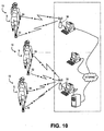
- the user interface 28 also enables users to receive real-time feedback and comparisons with other users and devices. For instance, as shown in FIG. 10 , a plurality of apparatuses 10 may be employed by a plurality of runners to enable data, metrics, and parameters corresponding to each runner to be shared and presented to the user. Thus, for instance, the user may ascertain the speed and location of other users through the user interface 28.
- the user interface 28 may acquire comparison information from the processing system 16 and/or from other devices through the communications element 26 to enable the user to compare his or her performance using the comparison information. For instance, the user interface 28 may present a comparison of the user's current performance with a previous performance by the user, with a training model, and/or with another individual.
- the user may configure the apparatus 10 utilizing the user interface 28 to monitor estimated motion parameters and alert the user through the user interface 28 when one or more estimated motion parameters conflict with a user-defined condition such as an acceptable parameter range, threshold, and/or variance.
- the user may also configure the apparatus 10 utilizing the user interface 28 to monitor various user-defined goals, such as time limits, motion parameter maximum values, and the like.
- the various components of the apparatus 10 may be housed integrally or separately in any combination.
- the apparatus 10 includes an interface unit 30 for housing the user interface 28 and associated components and_a sensor unit 32 for housing the one or more accelerometers 12 and the communications element 26.
- the processing system 16 (housed within both or either unit 30, 32) is operable to determine the attachment position of the sensor unit 32.
- the units 30, 32 may be housed within the same housing, as is shown in FIG. 9 .
- the units 30, 32 may be discrete such that the sensor unit 32 may be positioned in a first location, such as on the user's shoe, and the interface unit 30 may be positioned at a second location, such as on the user's wrist.
- the interface unit 30 may also include an interface communication element 34, configured in a similar manner to the communications element 26 discussed above, to enable the interface unit 30 to exchange information with the sensor unit 32, other parts of the apparatus 10, and/or with devices external to the apparatus 10.
- the communications elements 26, 34 may communicate utilizing the various wireless methods discussed above. However, the communications elements 26, 34 may also communicate utilizing wired connections or through external devices and systems.
- the units 30, 32 may also each include power sources for powering the various components of the apparatus 10, such as through the use of batteries or power-generating elements such as piezoelectric, electromechanical, thermoelectric, and photoelectric elements.
- portions of the user interface 28 may be included with both units 30, 32 such that each unit 30, 32 and its respective components can be individually functioned by the user.
- the apparatus 10 may additionally include an external systems unit 36 to enable the interface unit 30 and sensor unit 32 to easily communicate with external systems and devices.
- the external systems unit 36 may include a communications element to communicate with the other communication elements 26, 34, a microcontroller to process information, and a standard interface such as a WiFi, Bluetooth, ANT®, USB, or ZigBee interface operable to easily interface with devices such as cellular phones, portable media players, personal digital assistants, navigation devices, personal and portable computing devices, combinations thereof, and the like.
- the external systems unit 36 may be connected with an immobile personal computer and the interface unit 30 and sensor unit 32 may be positioned on a mobile user, as is shown in FIG. 10 .
- the interface unit 30 and sensor unit 32 may each be operable to communicate with the navigation unit 24 to receive and utilize navigation information.
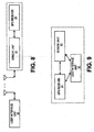
- the navigation device 24 may be discrete from the units 30, 32, as shown in FIG. 6 , the navigation device 24 may be integral with the interface unit 30, as shown in FIG. 7 , the navigation device 24 may be integral with the sensor unit 32, as shown in FIG. 8 , and/or the navigation device 24 may be integral with both units 30, 32, as shown in FIG. 9 . Further, in some embodiments, any one or more of the units 30, 32, 36 and navigation device 24 may be automatically disabled when not in use to achieve optimum system power consumption and functionality.
- the sensor unit 32 may be attached to the user's wrist in an enclosure which is similar to a watch and combined with other functionality such as timekeeping or with other sensors such the navigation device 24.
- the sensor unit 32 may be attached to the user's arm using an enclosure similar to an armband and combined with other devices such as a cellular phone, an audio device and/or the navigation device 24.
- the sensor unit 32 may be attached to the user with a chest strap in an enclosure which may include other sensors such as a heart-rate monitor (HRM).
- HRM heart-rate monitor
- the sensor unit 32 may be attached to user's waist with, for example, a belt clip.
- the sensor unit 32 may be attached to the top of a user's shoe with removable fasteners such as clips. In other embodiments, the sensor unit 32 may be inserted within the user's shoe, such as within a recess formed in the sole of the shoe.
- the sensor unit 32 may be operable to attach to more than one portion of the user.
- the sensor unit 32 may be adapted to attach to any of the various positions discussed above, including but not limited to, the user's wrist, arm, waist, chest, pocket, hat, glove, shoe (internal), and shoe (external).
- Such a configuration enables the same sensor unit 32, or apparatus 10, to be easily utilized by the user in a variety of positions to generate desirable motion parameters and/or to facilitate ease of use
- the apparatus 10 may be configured to identify its position on the user's body, thereby allowing the user to carry or attach the apparatus 10, or more particularly the sensor unit 32, in any of the above-identified positions or in any other arbitrary location, including in combination with other electronic devices such as a cellular phone.
- the processing system 16 may analyze one or more acceleration measurements generated by the one or more accelerometers 12. For a particular motion type such as striding, each attachment position and/or orientation will present a generally unique acceleration signature that may be identified by the processing system 16 to determine the attachment position and/or motion type of the accelerometers 12 or other portions of the apparatus 10, depending on how and/or where the accelerometers 12 are housed.
- FIG. 11 illustrates an exemplary acceleration signature corresponding to the sensor unit 32 mounted to the user's foot during striding
- FIG. 12 illustrates an exemplary acceleration signature corresponding to the sensor unit 32 mounted to the user's arm during striding
- FIG. 13 illustrates an exemplary acceleration signature corresponding to the sensor unit 32 mounting to the user's chest (torso) during striding.
- the processing system 16 may analyze measurements provided by the one or more accelerometers 12 and determine if the measurements correspond to a foot, arm, chest, or other striding acceleration signature. For example, by identifying the minimum(s), maximum(s), period, frequency, waveform, rate of change, combinations thereof, and the like, the processing system 16 may identify the acceleration signature, and thus the attachment position and/or motion type, of the sensor unit 32.
- the processing system 16 may determine the attachment position of the apparatus 10 by determining the orientation of the apparatus 10, or more specifically, the sensor unit 32. For example, if the sensor unit 32 is configured for mounting in two orientations, e.g., an upright orientation for mounting within a shoe and an inverted orientation for mounting on top of the shoe, the processing system 16 may analyze the acceleration measurements from the one or more accelerometers 12 to determine the orientation, e.g., upright or inverted, of the sensor unit 32 and thus where the sensor unit 32 is attached.
- the orientation of the apparatus 10 is not associated with any particular attachment position, as described above. Instead, different orientations may be associated with different activity types, or may be indicative of other conditions such as different terrain types, use by different users, and the like.
- the processing system 16 may analyze the acceleration measurements from the one or more accelerometers 12 to determine the orientation, e.g., upright or inverted, of the sensor unit 32, and thus determine that the activity type is one of either jogging or bicycling.
- the processing system 16 may analyze the acceleration measurements from the one or more accelerometers 12 to determine the orientation, e.g., forward facing or backward facing, of the sensor unit 32, and thus determine that the user engaged in the activity is a specific one of two users.
- the sensor unit 32 is configured for mounting in one specific orientation, e.g. on a chest strap or on the belt, and the activity type, e.g. jogging or swimming, determines the orientation of the sensor unit 32 relative to gravity.
- the processing system 16 may then analyze the acceleration measurements from the one or more accelerometers 12 to determine the orientation, e.g., parallel or perpendicular to gravity, of the sensor unit 32, and thus determine that the activity type is one of either jogging or swimming.
- the processing system 16 may identify the attachment position, orientation and/or motion type of the apparatus 10 and/or sensor unit 32 dynamically (i.e., on the fly) and/or store data corresponding to the acceleration measurements in the memory for later analysis and use. However, dynamic identification of the attachment position, orientation and/or motion type enables the processing system 16 to select an appropriate motion analysis algorithm for real-time user feedback of estimated and/or calculated motion parameters.
- the processing system 16 may be trained to identify new attachment positions. For example, the user could attach the sensor unit 32 in an arbitrary position, such as on the top of his or her head, and instruct the processing system 16 to enter a training mode during swimming to learn the acceleration signature of the new attachment position during the new motion type. During subsequent uses of the apparatus 10, the processing system 10 may automatically identify when the sensor unit 32 is in the new attachment position and/or when the new motion type is being performed based on the acceleration signature of the new position and/or the new motion type without requiring additional training by the user.
- the processing system 16 may also classify the motion currently being performed by the user based on one or more acceleration measurements provided by the one or more accelerometers 12.
- the processing system 16 may perform a motion classification analysis in addition to, or as an alternative to, the attachment position and motion type identification based on acceleration signature discussed above.
- the motion classification analysis may identify different types of gait, such as walking or running on flat or inclined surfaces, ascending stairs, descending stairs, climbing ladders, combinations thereof, and the like.
- the apparatus 10 includes at least two accelerometers 12 which provide signals for use by the processing system 16 to determine a striding motion angle.
- the two accelerometers 12 can be mounted on the foot in a substantially mutually perpendicular orientation and in the sagittal plane of the user, and generate acceleration measurements a 0 ( t ) and a 1 ( t ).
- a rotation sensor can be used to measure the change in angle, ⁇ ( t ), in the sagittal plane.
- the rotation sensor is a pair of spaced substantially parallel accelerometers 12 which can be used to calculate angular acceleration based on the difference of the signals.
- the rotation sensor is a gyroscope.
- Acceleration and rotational signals are sampled and stored for the duration of each stride T and processed as detailed in the exemplary block diagram of FIG. 14 .
- the reference frame can be defined by the arbitrary orientation in the sagittal plane of the apparatus 10, or more specifically the sensor unit 32, at the start of each stride.
- the point of reference in time is chosen for each stride such that the sensor unit 32 is substantially stationary and the reference frame is substantially consistent between strides.
- Computing the average acceleration vector from the start to end of each stride yields a vector measurement that is substantially defined by gravity. This allows for the transformation of measured acceleration vector, velocity and displacement from the arbitrary reference frame to a reference frame defined by gravity.
- the angle of motion can be calibrated for a particular subject's gait and mounting of the sensor unit 32 on the user's body.
- One method of calibration is to remove the average offset of motion angle from zero when the subject is walking on a flat surface.
- the angle of motion can be used to classify the surface incline or decline that is currently being traversed, as is illustrated in FIGS. 15-16 .
- a third accelerometer is included.
- the third accelerometer is mounted in a direction substantially perpendicular to the other two accelerometers.
- the acceleration measured by the third accelerometer is used to estimate the amount of motion perpendicular to the sagittal plane. This estimate may be used to compensate the motion angle measurement for motion perpendicular to the sagittal plane.
- the motion angle may be determined using average acceleration. Acceleration measurements provided by the one or more accelerometers 12 can be averaged to at least partially extract the DC (0 Hz) component of acceleration. Over sufficiently long time periods, DC acceleration is primarily attributable to acceleration due to gravity. Consequently, measurement of the gravity vector is used to determine the average orientation of the sensor unit 32 relative to the direction of gravity (vertical). Direction of motion can thus be estimated if the orientation of the measurement frame of reference is known relative to the direction of motion (i.e. unit mounting orientation on the body).
- a single accelerometer may be used. This configuration may assume that the vector representing direction of motion is in a known plane, such as the sagittal plane of the user. Under these constraints, the average acceleration measured by the accelerometer varies sinusoidally with the angle between the measurement frame of reference and vertical. The motion angle can thus be calculated by the processing system 16 if the orientation of the measurement frame of reference is known relative to the direction of motion.
- two accelerometers may be used to improve accuracy over the above-described single accelerometer configuration.
- the two accelerometers measure accelerations in two substantially perpendicular directions, both of which are substantially within a known plane, such as the sagittal plane of the user.
- Combining the two acceleration measurements into an acceleration vector and averaging over sufficiently long periods of time measures the gravity acceleration vector in the measurement frame of reference.
- the angle of the measured gravity acceleration vector, combined with the known orientation of the measurement frame of reference relative to the direction of motion measures the motion angle.
- three accelerometers may be used in situations where the vector representing direction of motion is not in a known plane.
- the three accelerometers measure accelerations in three mutually substantially perpendicular directions.
- Combining the three acceleration measurements into an acceleration vector and averaging over sufficiently long periods of time measures the gravity acceleration vector in the measurement frame of reference.
- the angle of the measured gravity acceleration vector combined with the known orientation of the measurement frame of reference relative to the direction of motion measures the motion angle.
- the motion angle determined by the processing system 16 may be used to classify the motion of the user, such as by classifying the gait of the user.
- the motion angle may also be utilized by the processing system 16 to determine output power.
- Athletes are often interested in the amount of power output by the body during an activity.
- the body power output is consumed in several ways, one of which is to overcome gravity.
- the body power output can be calculated as the sum of the ways in which power is consumed. For a particular speed, power needed to overcome the force of gravity increases with increasing incline angle. For a particular speed, as decline angle increases the amount of power contributed to the motion by gravity increases. Gravity does not influence the output power for motion on flat surfaces. Thus, information about angle of motion may be utilized the processing system 16 to determine output power.
- Acceleration measurements may also be used by the processing system 16 to classify whether or not the user's motion is cyclical.
- the processing system 16 may analyze one or more acceleration measurements generated by the one or more accelerometers 12.
- One or several of many known spectral analysis techniques such as FFT, digital filtering, analogue filtering, peak counting, and the like may be employed to identify the dominant frequency components of acceleration measurements or measure the signal power in particular frequency bands.
- Motion could be classified as cyclical if the dominant frequency component is within a specific frequency band.
- motion could be classified as cyclical if sufficient signal power exists within a specific frequency band.
- the specific frequency band could be 0.25Hz to 5Hz. Classification of the user's motion as cyclical enables the processing system 16 to calculate cadence. Cyclical components can be found in, for example, walking, jogging, running, cycling, exercising on an elliptical trainer, rowing, etc.
- Acceleration measurements provided by the one or more accelerometers 12 may also be used to classify terrain type during activities such as jogging, bicycling, and the like. During activities such as jogging or bicycling, rough terrain types generate more energy in high-frequency components of acceleration measurements than smooth terrain types.
- the processing system 16 may analyze one or more acceleration measurements generated by the one or more accelerometers 12.
- One or several of many known spectral analysis techniques such as FFT, digital filtering, analogue filtering, peak counting, and the like may be employed to measure the signal power in particular frequency bands. Motion terrain type could be classified as rough if sufficient signal power exists within a specific frequency band or above a specific frequency. For example, the specific frequency could be 10Hz.
- Rough terrain types can be further sub-classified. For example, bicycling on shale or gravel could be differentiated from bicycling on grass or earth and rocks, based on relative signal power in specific bands above the specific frequency. Terrain classification can be used in, for example, suspension control on bicycles or in active-prosthetic control.
- the processing system 16 may additionally utilize the acceleration measurements to classify striding motion.
- striding motion is classified into gait types by looking at the "stationary period".
- the stationary period is the amount of time the foot remains substantially stationary while walking.
- the stationary period can be determined by examining foot accelerations measured by the one or more accelerometers 12.
- the stationary period for walking is distinguishably longer than for jogging or running.
- the stationary period decreases as the speed of motion increases.
- the stationary period can be but is not necessarily equal to the duration of the stance phase.
- Acceleration measurements may thus be used by the processing system 16 to classify a complete range of activities by utilizing combinations of various techniques including the acceleration signature identification, determination of angle of motion, determination of output power, identification of cyclical motion, terrain type classification, gait type classification and the like.
- Activities which can, for example, be classified or otherwise identified by the processing system 16 include: walking; jogging; running; swimming; bicycling, racquet sports; rowing, skiing, shuffling; driving; exercising on a stationary bicycle or other stationary apparatus such as an elliptical trainer; hiking; rollerblading; skateboarding; low-energy activities such as office activities and watching television; sleeping; dancing; playing sports such as basketball, football, soccer or golf; combinations thereof; and the like.
- the apparatus 10 may automatically provide information for a plurality of activities without requiring manual reconfiguration or programming by the user.
- the processing system 16 may additionally or alternatively classify the user's striding motion as healthy or abnormal based on measurements provided by the one or more accelerometers 12. For example, the processing system 16 may detect irregularities in the user's gait; e.g. abnormal swing characteristics, onset of a drop-foot condition, etc, by comparing the real-time determined characteristics, such as motion angle or determined motion parameters, against known, normal, stored values.
- a sensor unit 32 could be worn on each foot/leg to look for gait asymmetries, for example. Such a configuration could be used in rehabilitation and training performance optimization.
- pronation/supination conditions are measured with a gyro, such as gyroscope housed within the sensor unit 32.
- the amount of foot roll in a plane substantially perpendicular to the direction of motion is measured by integrating angular velocity.
- pronation/supination conditions are measured with two accelerometers substantially parallel, separated by a fixed distance, such as two of the accelerometers 12 discussed above.
- the measured translational accelerations can be used to compute angular acceleration which can be doubly integrated to obtain the amount of foot roll in a plane substantially perpendicular to the direction of travel.
- pronation/supination conditions are measured with one of the accelerometers 12 by estimating the direction of the gravity vector relative to the orientation of the foot, before and after foot strike. This can be done with one, two or three of the accelerometers 12.
- One and two-accelerometer embodiments make an assumption that the accelerometer is free to rotate only in the plane substantially perpendicular to the direction of motion.
- a tri-axial embodiment can be mounted on the foot in an arbitrary location.
- the processing system 16 may also classify motion based on the severity of impacts associated with the motion. For example, running on pavement with poor technique can be associated with substantial impacts and can thus result in substantial joint stress and wear. Exercising on an elliptical trainer, on the other hand, is associated with minimal or no impacts. Accelerometer measurements can be used to identify impact characteristics which can be used by the processing system 16 to estimate impact force and/or joint stress associated with impacts. The user may be interested in knowing instantaneous impact levels for a particular motion type, or a cumulative amount of joint stress over an activity session or over longer periods of time. Thus, the user interface 28 may inform the user of the determined motion angle, the motion classification, impact power, combinations thereof, and the like.
- the processing system 16 may determine the suitability of footwear for a particular user or a particular activity based on impact level measurements. In another embodiment the quality of footwear may be monitored over time with impact level measurements to determine when the footwear should be replaced.
- the processing system 16 may also estimate the fatigue or efficiency of the user by identifying changes in the impact levels over time during an exercise activity as the user's foot strike will start to become more choppy and less regular, which will manifest as inconsistent acceleration patterns. Utilizing the user interface 28, the processing system 16 can also provide real-time bio-feedback as to the user's rehabilitation from a stroke or accident, for example, by denoting the level and direction of foot impact compared to established norms.
- the processing system 16 may select one or more motion analysis algorithms that may be used to determine one or more motion parameters.
- the memory may include a database of motion analysis algorithms corresponding to various combinations of attachment positions and motion classifications.
- the memory may include motion analysis algorithms for: foot, chest, and arm attachment locations; walking, running, swimming, and biking algorithms; and/or walking, running, swimming, and biking algorithms for each of the foot, chest, and arm attachment positions.
- the processing system 16 may select a suitable motion analysis algorithm from the memory or other sources (including external sources) for any identified attachment position or classified motion. Selection of motion analysis algorithms corresponding to an identified attachment position and/or classified motion facilitates in the accurate determination of motion parameters.
- the processing system 16 may additionally or alternatively select the motion analysis algorithm based on one or more user characteristics, such as age, gender, weight, height, configuration, shape, and the like.
- the processing system 16 may also select the motion analysis algorithm based on the configuration of the apparatus 10, such as the number and type of accelerometers 12 utilized, the number of acceleration measurements received, combinations thereof, and the like.
- the selected motion analysis algorithm may include a statistical model, such as a regression model selected from the group consisting of a linear regression model, a polynomial regression model, a multiple-regression model, a piecewiselinear regression model, combinations thereof, and the like.
- a statistical model such as a regression model selected from the group consisting of a linear regression model, a polynomial regression model, a multiple-regression model, a piecewiselinear regression model, combinations thereof, and the like.
- the processing system 16 may estimate, calculate, identify, or otherwise determine one or more motion parameters.
- the motion parameter may correspond to stride speed, acceleration, velocity, stride distance, total distance, gait efficiency, power, energy, maximum impact, average calories consumed, maximum speed change, speed variability, stroke power, lap time, strike time, steps, cadence, combinations thereof, and the like.
- the motion parameter determined by the processing system 16 may correspond to any parameter associated with the motion of the user.
- the processing system 16 may estimate the stride duration of a human or animal using measurements provided by the one or more accelerometers 12 and the selected motion analysis algorithm. For instance, based on various changes in accelerations measured by the one or more accelerometers 12, the processing system 16 may be able to determine the time at which a stride begins and ends, such as by determining when a runner's foot impacts the ground, when a runner's foot leaves the ground, when a runner's foot is stationary relative to the ground, combinations thereof, and the like. Thus, by analyzing various changes in measured accelerations, the processing system 16 may compute the stride duration and information corresponding thereto, such as stride frequency. The stride frequency may represent the number of strides per second or other indications of the rate of stride.
- the processing system 16 may provide the stride duration and/or stride frequency to the filtering element 14 for use in determining the various cut-off frequencies discussed above.
- the processing system 16 may dynamically determine the stride duration and stride frequency based on received acceleration measurements and the filtering element 14 may adapt to provide accurate filtration based on the particular performance of the user.
- the filtering element 14 may filter perpendicular acceleration based on the stride frequency calculated by the processing system 16 to facilitate the accurate estimation of the motion parameter.
- Any motion analysis algorithm may be utilized by the processing system 16, including the motion parameter metrics and statistical models disclosed in Patent Application US 2007/208544 A1 .
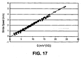
- the processing system 16 may correlate a generated motion parameter metric to stride speed as shown in the regression model of FIG. 17 .
- the estimation/calculation/determination performed by the processing system 16 may generally correspond to any correlation between the selected motion analysis algorithm and one or more motion parameters and is not necessarily a direct computation based on user kinematics. Consequently, the processing system 16 may estimate the motion parameter utilizing statistics and/or other empirical information even when a direct computation of the motion parameter is difficult or impossible to perform.
- the processing system 16 may utilize a database, a look-up table, or other information stored within the memory, or any other computer-readable medium, to estimate the motion parameter using the selected motion analysis algorithm. For example, given a particular set of acceleration measurements, attachment positions, and/or classified motions, the processing system 16 may access the memory to acquire a corresponding motion parameter.
- the processing system 16 is operable to compute the motion parameter metric and/or estimate the motion parameter for each detected stride to facilitate the accurate analysis of movement. Thus, for every stride detected as discussed above, or for any combination of strides, the processing system 16 may estimate the motion parameter. Further, in some embodiments, the processing system 16 may estimate the motion parameter using algorithms corresponding to a plurality of strides. For example, the estimated motion parameter may correspond to a total or average stride speed resulting from several strides.
- the apparatus 10 is operable to estimate motion parameters using only acceleration measurements acquired from the one or more accelerometers 12, using acceleration measurements in combination with other information acquired from the navigation unit 24 or other devices through the communications element 26, using information other than acceleration measurements, combinations thereof, and the like.
- the processing system 16 may utilize acceleration measurements and/or other information, such as the identified attachment position or classified motion, to automatically provide appropriate content based upon the identified activity without requiring user input. For example, if the user switches from walking to jogging, the processing system 16 may identify the change, compute jogging-related metrics and motion parameters, and display jogging-related information using the user interface 28. As another example, the processing system 16 may identify that the user is swimming and that the sensor unit 32 is mounted on the user's arm based upon the acceleration measurements and generate and display swimming-related information such as cadence, stroke power, lap times, and the like.
- acceleration measurements and/or other information such as the identified attachment position or classified motion
- the processing system 16 may be configured to utilize a multi-resolution approach in storing information and data corresponding to sensed measurements and activities. For example, at the lowest resolution, the time, date, classification, duration and total energy expenditure of each activity may be saved. Another resolution may allow data to be stored corresponding to, for example, for jogging, the average pace, average cadence, total distance, total elevation change, and the like. Another resolution may allow data to be stored corresponding to, again for jogging, for example, individual stride parameters and/or frequent measurements of heart rate, elevation, pace, and/or associated GPS coordinates. The history resolution depth for each type of activity can be pre-selected by the user or be automatically selected by the processing system 16 based on the amount of storage space available.
- all activities are initially recorded at the highest available resolution; subsequently, if storage space becomes a constraint, highest resolution records of oldest activities may be erased to allow for storage of the most recent activities at a history resolution at least as good as resolution of the oldest records.
- the processing system 16 may provide context-aware functionality utilizing measured accelerations, identified attachment positions, classified motions, selected algorithms, estimated motion parameters, information acquired through the user interface 28, information acquired through communications element 26 or other devices such as the navigation device 24, combinations thereof, and the like.
- the processing system 16 may detect: if the apparatus 10 is being used to estimate motion parameters or monitor user performance; if the apparatus 10 is not being used; if the apparatus 10 is being charged; if the apparatus 10 is in proximity to a compatible external system or device; if the apparatus 10 is in proximity to a display device such as a cellular phone, personal digital assistant, computer, audio device, heads-up display, watch; combinations thereof; and the like.
- the apparatus 10 can provide any appropriate set of functions. For example, while in proximity to a compatible external system, the apparatus 10 can automatically establish a communication channel and exchange information with the compatible external system. Similarly, while monitoring user activity, the apparatus 10 can record motion history and associated motion parameters. While not in use, the apparatus 10 can disable most of its sensors to conserve energy and enable a subset of the sensors, such as the one or more accelerometers 12, only frequently enough to maintain context awareness. While in proximity to a display device, the apparatus 10 can determine the capabilities of the device, and communicate appropriate information to the display device.
- the use contexts are not necessarily mutually exclusive. For example, the apparatus 10 can be charging and be in proximity to a compatible external system at the same time.
- the apparatus 10 can continue the sensing of nearby compatible external systems and, upon detection of a compatible external system, establish a communication channel and exchange information with the compatible external system.
- the user thus perceives and expects the apparatus 10 to be always enabled and the apparatus 10 requires minimal or no user input to perform all of its functions.
- the activity monitoring and/or context awareness discussed above may be utilized by the apparatus 10 to maintain a generally continuous record of the user's activities.
- the user may wear the apparatus 10 continuously or repeatedly to monitor long-term activity, such as trends, goals, and the like.
- Generally continuous monitoring of user activity by the apparatus 10 also enables alerts to be issued if the processing system 16 detects abnormal activity. For example, if the user remains generally immobile for extended periods of time, the processing system 16 may issue an alert to notify the user through the user interface 28 and/or alert third-parties utilizing the communications element 26.
Abstract
Description
- Embodiments of the present invention relate to methods and apparatuses for , determining the attachment position of a motion sensing apparatus. More particularly, various embodiments of the invention provide methods and apparatuses operable to determine the attachment position of a motion sensing apparatus using acceleration measurements sensed by the motion sensing apparatus.
- Motion sensing apparatuses are often used to sense the motion of an object, animal, or person. For example, sensed and calculated motion parameters, such as acceleration, average velocity, stride distance, total distance, gait efficiency, and the like, may be utilized in the training and evaluation of athletes and animals, the rehabilitation of the injured and disabled, and in various recreational activities.
- Motion sensing apparatuses must often be attached to specific location, such as a user's shoe, arm, or wrist, to correctly sense and calculate motion parameters. Thus, if a motion sensing apparatus is attached to an incorrect location, it may function incorrectly. Further, differently configured motion sensing apparatuses must be employed for different attachment positions, thereby preventing users from using the same motion sensing apparatus in more than one attachment configuration.
EP 1 619 475 A2US 2006/0112754 A1 discloses an action/posture detector that judges its attachment position and corrects the directions of the acceleration sensor. - In various embodiments the present invention provides a motion sensing apparatus generally comprising a housing unit operable to be attached to an object at an attachment position, an accelerometer operable to provide a signal corresponding to an acceleration measurement, and a processing system. The processing system is operable to acquire the signal corresponding to the acceleration measurement, analyze the acquired acceleration measurement to identify the attachment position of the housing unit, select a motion analysis algorithm based on the identified attachment position, and determine a motion parameter utilizing the selected motion analysis algorithm.
- It is to be understood that both the foregoing general description and the following detailed description are exemplary and explanatory only and are not necessarily restrictive of the invention claimed. The accompanying drawings, which are incorporated in and constitute a part of the specification, illustrate embodiments of the invention and together with the general description, serve to explain the principles of the invention.
- Various embodiments of the present invention are described in detail below with reference to the attached drawing figures, wherein:
-
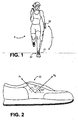
FIG. 1 is a schematic diagram illustrating a user employing a sensor unit and a user interface unit configured in accordance with various embodiments of the present invention; -
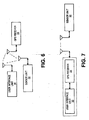
FIG. 2 is a schematic diagram illustrating an exemplary orientation of various sensors within or on a shoe; -
FIG. 3 is a block diagram illustrating some of the components operable to be utilized by various embodiments of the present invention; -
FIG. 4 is a block diagram illustrating some of the components ofFIG. 3 in more detail; -
FIG. 5 is a block diagram illustrating an external systems unit in communication with the sensor unit and user interface unit ofFIG. 1 ; -
FIG. 6 is a block diagram illustrating the user interface unit and sensor unit ofFIG. 5 in communication with a GPS receiver; -
FIG. 7 is a block diagram illustrating another configuration of the user interface unit and GPS receiver ofFIG. 5 ; -
FIG. 8 is a block diagram illustrating another configuration of the sensor unit and GPS receiver ofFIG. 5 ; -
FIG. 9 is a block diagram illustrating another configuration of the GPS receiver, user interface unit, and sensor unit ofFIG. 5 ; -
FIG. 10 is a schematic diagram showing the interaction of a plurality of apparatuses configured in accordance with various embodiments of the present invention; -
FIG. 11 is an exemplary acceleration signature for a foot-mounted sensor unit; -
FIG. 12 is an exemplary acceleration signature for an arm-mounted sensor unit; -
FIG. 13 is an exemplary acceleration signature for a chest-mounted sensor unit; -
FIG. 14 is a block diagram illustrating an exemplary processing method; -
FIG. 15 is an exemplary diagram illustrating motion angle; -
FIG. 16 is an exemplary diagram showing the relationship between motion angle and surface incline or decline; and -
FIG. 17 is a chart showing an exemplary correlation between a motion parameter metric and stride speed. - The drawing figures do not limit the present invention to the specific embodiments disclosed and described herein. The drawings are not necessarily to scale, emphasis instead being placed upon clearly illustrating various embodiments of the invention.
- The following detailed description of various embodiments of the invention references the accompanying drawings which illustrate specific embodiments in which the invention can be practiced. The embodiments are intended to describe aspects of the invention in sufficient detail to enable those skilled in the art to practice the invention. Other embodiments can be utilized and changes can be made without departing from the scope of the present invention. The following detailed description is, therefore, not to be taken in a limiting sense. The scope of the present invention is defined only by the appended claims, along with the full scope of equivalents to which such claims are entitled.
- Various embodiments of the present invention provide a
motion sensing apparatus 10 operable to determine its attachment position based on one or more acceleration measurements. Theapparatus 10 may select a motion analysis algorithm based on the identified attachment position and determine a motion parameter using the selected motion analysis algorithm. - In various embodiments, the
apparatus 10 can include one ormore accelerometers 12, afiltering element 14, and aprocessing system 16. Theaccelerometers 12,filtering element 14, andprocessing system 16 may be integrated together or form discrete elements that may be associated with each other. Theprocessing system 16 is generally operable to analyze measurements provided by the one ormore accelerometers 12 to determine the attachment position of theapparatus 10. - The one or
more accelerometers 12 are each operable to measure an acceleration and generate an acceleration measurement corresponding to the measured acceleration. The acceleration measurement may be embodied as a signal operable to be utilized by thefiltering element 14 and/orprocessing system 16. In some embodiments, one or more of theaccelerometers 12 may be operable to output an analog signal corresponding to an acceleration measurement. For instance, eachaccelerometer 12 may output an analog voltage signal that is proportional to measured accelerations. In some embodiments, one or more of theaccelerometers 12 may include the ADXL321 accelerometer manufactured by ANALOG DEVICES of Norwood, MA. However, the one ormore accelerometers 12 may include any digital and analog components operable to generate a signal corresponding to a measured acceleration. Thus, in some embodiments, one or more of theaccelerometers 12 are operable to output a digital signal representing measured accelerations. - In some embodiments, more than one of the
accelerometers 12 may be integrated into the same integrated circuit package to allow the single package to provide acceleration measurements along more than one axis. For example, as shown inFIG. 2 , theapparatus 10 may include two ormore accelerometers 12 each operable to output a signal corresponding to a measured acceleration. In some embodiments, theapparatus 10 includes at least twoaccelerometers 12 adapted to measure accelerations in two directions separated by an angle greater than zero degrees and each provide a signal corresponding to the measured acceleration. Further, theapparatus 10 may include at least threeaccelerometers 12 adapted to measure accelerations in three directions each separated by an angle greater than zero degrees and each provide a signal corresponding to the measured acceleration. In some embodiments, the threeaccelerometers 12 may be oriented in a mutually perpendicular configuration. However, theapparatus 10 may include any number ofaccelerometers 12, including asingle accelerometer 12, positioned in any configuration to provide acceleration measurements for use by thefiltering element 14 and/orprocessing system 16. - The one or more of the
accelerometers 12 may be operable to communicate with other elements of theapparatus 10, or elements external to theapparatus 10, through wired or wireless connections. Thus, theaccelerometers 12 may be coupled with thefiltering element 14 and/orprocessing system 16 through wires or the like. One or more of theaccelerometers 12 may also be configured to wirelessly transmit data toother apparatus 10 elements and devices external to theapparatus 10. For instance, one or more theaccelerometers 12 may be configured for wireless communication using various RF protocols such as Bluetooth, Zigbee, ANT®, and/or any other wireless protocols. - The
filtering element 14 is operable to couple with the one ormore accelerometers 12 and filter acceleration measurements and/or signals corresponding to acceleration measurements. In some embodiments, theapparatus 10 does not include thefiltering element 14 and theprocessing system 16 is operable to use unfiltered acceleration measurements and corresponding signals. In other embodiments, thefiltering element 14 may be integral with one or more of theaccelerometers 12, theprocessing system 16, or both theaccelerometers 12 and theprocessing system 16. For example, a first portion of thefiltering element 14 may be integral with one or more of theaccelerometers 12 and a second portion of thefiltering element 14 may be integral with theprocessing system 16. In other embodiments, thefiltering element 14 may be discrete from both theaccelerometers 12 and theprocessing system 16. - The
filtering element 14 may include analog and digital components operable to filter and/or provide other pre-processing functionality to facilitate the estimation of motion parameters by theprocessing system 16. In various embodiments as shown inFIG. 4 , thefiltering element 14 is operable to filter signals provided by the one ormore accelerometers 12, or signals derived therefrom, to attenuate perpendicular acceleration, to compensate for gravity, and/or to minimize aliasing. Thefiltering element 14 may include discrete components for performing each of these filtering functions or use the same components and hardware for these, and other, filtering functions. - The
filtering element 14 may include any analog and digital components for filtering signals and measurements, including passive and active electronic components, processors, controllers, programmable logic devices, digital signal processing elements, combinations thereof, and the like. In some embodiments, thefiltering element 14 may include a digital microcontroller, such as the MSP430F149 microcontroller manufactured by TEXAS INSTRUMENTS to provide various static and/or adaptive filters. Thefiltering element 14 may also include an analog-to-digital converter to convert analog signals provided by the one ormore accelerometers 12 to digitize signals for use by theprocessing system 16. Thefiltering element 14 may also include conventional pre-sampling filters. - In some embodiments, the low-
pass filter 18 may be an adaptive filter operable to employ static and/or varying cut-off frequencies between about 0.5 Hz and 10 Hz. In some embodiments where parameters corresponding to human strides are estimated, the low-pass filter 18 may employ cut-off frequencies between about 1 Hz and 3 Hz. Thefiltering element 14 may acquire the cut-off frequency from theprocessing system 16 based on computations performed by theprocessing system 16 corresponding to the particular stride frequency of the subject element S. The low-pass filter 18 may additionally or alternatively be adapted to employ a cut-off frequency corresponding to a gait type identified by theprocessing system 16. - In other embodiments, the cut-off frequency for the low-
pass filter 18 may be a static value based upon the typical stride frequency of a running or walking human. For instance, the cut-off frequency may correspond to a frequency between one and two times the typical stride frequency of a running and/or walking human, such as a static frequency between 1 Hz and 3 Hz. Specifically, in some embodiments, the cut-off frequency may be about 1.45Hz for walking humans and about 2.1 Hz for jogging humans. - The gravity compensation provided by the
filtering element 14 generally compensates for the constant acceleration provided by gravity that may be sensed by one or more of theaccelerometers 12. In some embodiments, thefiltering element 14 includes a high-pass filter 20 operable to filter or attenuate components of signals corresponding to measured accelerations below a given cut-off frequency. The cut-off frequency of the high-pass filter 20 may correspond to a frequency approaching 0 Hz, such as 0.1 Hz, to adequately provide compensation for gravity-related acceleration. - The anti-aliasing provided by the
filtering element 14 generally reduces or prevents aliasing caused by sampling of the signals provided by, or derived from, the one ormore accelerometers 12. In some embodiments, thefiltering element 14 includes a relativelywideband filter 22 designed to attenuate signal frequencies in excess of one-half of the sampling frequency used in any subsequent analog-to-digital conversions provided by theprocessing system 16 or other devices associated with theapparatus 10. In some embodiments, thefiltering element 14 may provide other filtering components instead of, or in addition to, thewideband filter 22 to compensate for aliasing. For instance, thefiltering element 14 may include one or more analog and/or digital filters to perform any combination of the various filtering functionality discussed herein. In some embodiments, a single filtering element may be utilized to perform each of the filtering functions discussed above such that separate or discrete filters are not necessarily employed for different filtering functions. - The
processing system 16 is generally operable to couple with the one ormore accelerometers 12 and/or thefiltering element 14 to identify the attachment position of themotion sensing apparatus 10, and more specifically, the attachment position of the one ormore accelerometers 12. Theprocessing system 16 may include various analog and digital components operable to perform the various functions discussed herein. In some embodiments, theprocessing system 16 may include a microprocessor, a microcontroller, a programmable logic device, digital and analog logic devices, computing elements such as personal computers, servers, portable computing devices, combinations thereof, and the like. - The
processing system 16, filteringelement 14,accelerometers 12, and/or other portions of theapparatus 10 may limit or expand the dynamic range of acceleration measurements used to generate the motion parameter metric and/or identify attachment position. For example, acceleration measurements outside a specified dynamic range, such as plus or minus 8g, may be saturated at the dynamic range limits to further limit the effects of perpendicular acceleration. Alternatively, linear or non-linear amplifiers may be used to increase or reduce the dynamic range. The dynamic range may be varied by theprocessing system 16 based on the particular motion parameter being estimated or according to other sensed or generated measurements. - The
processing system 16 may also include, or be operable to couple with, a memory. The memory may include any computer-readable memory or combination of computer-readable memories operable to store data for use by theprocessing system 16. For instance, the memory may be operable to store acceleration data, motion parameter metric data, statistical data, motion parameter data, filtering data, configuration data, combinations thereof, and the like. - The
processing system 16 may be discrete from thevarious accelerometers 12 andfiltering element 14 discussed above. In other embodiments, theprocessing system 16 may be integral with other portions of theapparatus 10. For instance, the same microcontroller or microprocessor may be utilized to implement thefiltering element 14 and theprocessing system 16. - In some embodiments, data and information generated by the
accelerometers 12, filteringelement 14, and/orprocessing system 16 may be stored in the memory associated with theprocessing system 16, or in any other computer-readable memory, to allow later analysis by theprocessing system 16 or other devices associated therewith. The stored information may be time-correlated to facilitate analysis and compressed to reduce the required capacity of the memory. - The
processing system 16 may additionally or alternatively utilize information acquired from sensors other than the one ormore accelerometers 12. For instance, in some embodiments theprocessing system 16 may couple with a heart rate monitor, acquire heart rate information from the heart rate monitor, and identify the attachment position of theapparatus 10 and/or generate a motion parameter using the heart rate information and/or acceleration measurements. Similarly, theprocessing system 16 may couple with other sensors to acquire non-acceleration kinematic variables such as velocity and/or environmental variables such as ambient temperature and altitude. For example, to acquire additional information, theprocessing system 16 may couple with, and/or include, radio-frequency transceivers, thermometers, altimeters, compasses, inclinometers, pressure sensors, blood pressure monitors, light sensors, atmospheric sensors, angular velocity sensors and other inertial sensors, microphones, computing devices such as personal computers, cellular phones, and personal digital assistances, other similarly configured apparatuses, combinations thereof, and the like. - In some embodiments, as shown in
FIGS. 6 through 9 , theapparatus 10 may be operable to receive information from at least onenavigation device 24. Thenavigation device 24 may be adapted to provide geographic location information to theapparatus 10 and users of theapparatus 10. Thenavigation device 24 may include a GPS receiver much like those disclosed inU.S. Patent No. 6,434,485 . However, thenavigation device 24 may use cellular or other positioning signals instead of, or in addition to, the GPS to facilitate determination of geographic locations. Thenavigation device 24 may be operable to generate navigation information such as the speed of thenavigation device 24, the current and previous locations of thenavigation device 24, the bearing and heading of thenavigation device 24, the altitude of thenavigation device 24, combinations thereof, and the like. - The
processing system 16 may use the information received from thenavigation device 24 to generate a motion parameter metric and/or identify the attachment position of theapparatus 10. Theprocessing system 16 may also use and present acquired navigation information independent of the metrics and estimated parameters. Additionally or alternatively, theprocessing system 16 may use the information acquired from thenavigation device 24 to correct and/or adjust calculated information. For instance, theprocessing system 16 may compare distances and speeds generated from accelerations provided by the one ormore accelerometers 12 with distances and speeds provided by thenavigation device 24 and correct calculated measurements to enable distances and speeds generated from measured accelerations to be as accurate as those provided by thenavigation device 24. Thus, theprocessing system 16 may be periodically coupled with thenavigation device 24 to correct information to ensure that theapparatus 10 accurately estimates motion parameters even when not coupled with thenavigation device 24. - The
filtering element 14 andprocessing system 16 may additionally be operable to compensate for part-to-part manufacturing variability present in the one ormore accelerometers 12, including characterization over temperature of zero-g bias point, sensitivity, cross-axis sensitivity, nonlinearity, output impedance, combinations thereof, and the like. - In some embodiments, as shown in
FIG. 5 , theapparatus 10 may include acommunications element 26 to enable theapparatus 10 to communicate with other computing devices, exercise devices, navigation devices, sensors, and any other enabled devices through a communication network, such as the Internet, a local area network, a wide area network, an ad hoc or peer to peer network, combinations thereof, and the like. Similarly, thecommunications element 26 may be configured to allow direct communication between similarly configured apparatuses using USB, ANT®, Bluetooth, Zigbee, Firewire, and other connections, such that theapparatus 10 need not necessarily utilize a communications network to acquire and exchange information. - In various embodiments the
communications element 26 may enable theapparatus 10 to wirelessly communicate with communications networks utilizing wireless data transfer methods such as WiFi (802.11), Wi-Max, Bluetooth, ultra-wideband, infrared, cellular telephony, radio frequency, and the like. However, thecommunications element 26 may couple with the communications network utilizing wired connections, such as an Ethernet cable, and is not limited to wireless methods. - The
communications element 26 may be configured to enable theapparatus 10 to exchange data with external computing devices to facilitate the generation and/or analysis of information. For example, theprocessing system 16 may use information acquired through thecommunications element 26 in identifying the attachment position of theapparatus 10, in generating the motion parameter metrics, and/or in estimating motion parameters. Theprocessing system 16 may also provide generated motion parameter metrics and estimated motion parameters through thecommunications element 26 for use by external devices. For instance, the external devices can be configured to store, analyze, and exchange information between a plurality of users and/or a plurality of devices attached to one or multiple users. - Consequently, the
communications element 26 generally enables real-time comparison of information generated by theapparatus 10 and other devices. Thecommunications element 26 also enables theapparatus 10 to store data on one or more of the external devices for later retrieval, analysis, aggregation, and the like. The data can be used by individuals, their trainers or others to capture history, evaluate performance, modify training programs, compare against other individuals, and the like. The data can also be used in aggregated form. - The
apparatus 10 may additionally include auser interface 28 to enable users to access various information generated and acquired by theapparatus 10, such as attachment positions, acceleration measurements, motion parameter metrics, estimated motion parameters, navigation information acquired from thenavigation device 24, information and data acquired through thecommunications element 26, configuration information, combinations thereof, and the like. Theuser interface 28 facilities, for example, powering on/off theapparatus 10, selecting which content to display, and providing configuration information such as the attributes of the subject element S. - The
user interface 28 may include one or more displays to visually present information for consumption by users and one or more speakers to audibly present information to users. Theuser interface 28 may also include mechanical elements, such as buzzers and vibrators, to notify users of events through mechanical agitation. In some embodiments, as shown inFIG. 1 , theuser interface 28 may be implemented within a watch operable to be worn on a user's wrist, forearm, and/or arm. Thus, theuser interface 28 may be positioned separately from one or more of theaccelerometers 12 to enable the user to easily interact with theapparatus 10. However, in some embodiments theuser interface 28 andaccelerometers 12 may be integral. - The
user interface 28 may also be operable to receive inputs from the user to control the functionality of theprocessing system 16 and/or devices and elements associated therewith. Theuser interface 28 may include various functionable inputs such as switches and buttons, a touch-screen display, optical sensors, magnetic sensors, thermal sensors, inertial sensors, a microphone and voice-recognition capabilities, combinations thereof, and the like. Theuser interface 28 may also include various processing and memory devices to facilitate its functionality. - The
user interface 28 enables users to receive real-time feedback concerning the estimated motion parameter and associated information. For instance, theuser interface 28 may present the currently estimated motion parameter, such as a current stride speed and distance, and/or information associated therewith or with other motion parameters, such as total distance, calories expended, total speed, combinations thereof, and the like. - Utilizing the
communications element 26, theuser interface 28 also enables users to receive real-time feedback and comparisons with other users and devices. For instance, as shown inFIG. 10 , a plurality ofapparatuses 10 may be employed by a plurality of runners to enable data, metrics, and parameters corresponding to each runner to be shared and presented to the user. Thus, for instance, the user may ascertain the speed and location of other users through theuser interface 28. - Further, the
user interface 28 may acquire comparison information from theprocessing system 16 and/or from other devices through thecommunications element 26 to enable the user to compare his or her performance using the comparison information. For instance, theuser interface 28 may present a comparison of the user's current performance with a previous performance by the user, with a training model, and/or with another individual. - In various embodiments, the user may configure the
apparatus 10 utilizing theuser interface 28 to monitor estimated motion parameters and alert the user through theuser interface 28 when one or more estimated motion parameters conflict with a user-defined condition such as an acceptable parameter range, threshold, and/or variance. The user may also configure theapparatus 10 utilizing theuser interface 28 to monitor various user-defined goals, such as time limits, motion parameter maximum values, and the like. - As is discussed above, the various components of the
apparatus 10 may be housed integrally or separately in any combination. In some embodiments, theapparatus 10 includes aninterface unit 30 for housing theuser interface 28 and associated componentsand_a sensor unit 32 for housing the one ormore accelerometers 12 and thecommunications element 26. In such embodiments, the processing system 16 (housed within both or eitherunit 30, 32) is operable to determine the attachment position of thesensor unit 32. In some embodiments, theunits FIG. 9 . However, in other embodiments theunits sensor unit 32 may be positioned in a first location, such as on the user's shoe, and theinterface unit 30 may be positioned at a second location, such as on the user's wrist. - The
interface unit 30 may also include aninterface communication element 34, configured in a similar manner to thecommunications element 26 discussed above, to enable theinterface unit 30 to exchange information with thesensor unit 32, other parts of theapparatus 10, and/or with devices external to theapparatus 10. In embodiments where theunits communications elements communications elements - The
units apparatus 10, such as through the use of batteries or power-generating elements such as piezoelectric, electromechanical, thermoelectric, and photoelectric elements. In some embodiments, portions of theuser interface 28 may be included with bothunits unit - As shown in
FIG. 5 , theapparatus 10 may additionally include anexternal systems unit 36 to enable theinterface unit 30 andsensor unit 32 to easily communicate with external systems and devices. For example, theexternal systems unit 36 may include a communications element to communicate with theother communication elements external systems unit 36 may be connected with an immobile personal computer and theinterface unit 30 andsensor unit 32 may be positioned on a mobile user, as is shown inFIG. 10 . - As is shown in
FIGS. 6 through 9 , theinterface unit 30 andsensor unit 32 may each be operable to communicate with thenavigation unit 24 to receive and utilize navigation information. Thenavigation device 24 may be discrete from theunits FIG. 6 , thenavigation device 24 may be integral with theinterface unit 30, as shown inFIG. 7 , thenavigation device 24 may be integral with thesensor unit 32, as shown inFIG. 8 , and/or thenavigation device 24 may be integral with bothunits FIG. 9 . Further, in some embodiments, any one or more of theunits navigation device 24 may be automatically disabled when not in use to achieve optimum system power consumption and functionality. - In some embodiments, the
sensor unit 32 may be attached to the user's wrist in an enclosure which is similar to a watch and combined with other functionality such as timekeeping or with other sensors such thenavigation device 24. In other embodiments, thesensor unit 32 may be attached to the user's arm using an enclosure similar to an armband and combined with other devices such as a cellular phone, an audio device and/or thenavigation device 24. In various other embodiments, thesensor unit 32 may be attached to the user with a chest strap in an enclosure which may include other sensors such as a heart-rate monitor (HRM). In yet other embodiments, thesensor unit 32 may be attached to user's waist with, for example, a belt clip. In further embodiments, thesensor unit 32 may be attached to the top of a user's shoe with removable fasteners such as clips. In other embodiments, thesensor unit 32 may be inserted within the user's shoe, such as within a recess formed in the sole of the shoe. - In some embodiments, the
sensor unit 32, and/or more generally theapparatus 10, may be operable to attach to more than one portion of the user. For example, thesensor unit 32 may be adapted to attach to any of the various positions discussed above, including but not limited to, the user's wrist, arm, waist, chest, pocket, hat, glove, shoe (internal), and shoe (external). Such a configuration enables thesame sensor unit 32, orapparatus 10, to be easily utilized by the user in a variety of positions to generate desirable motion parameters and/or to facilitate ease of use - In some embodiments, the
apparatus 10 may be configured to identify its position on the user's body, thereby allowing the user to carry or attach theapparatus 10, or more particularly thesensor unit 32, in any of the above-identified positions or in any other arbitrary location, including in combination with other electronic devices such as a cellular phone. - To identify the attachment position of the
sensor unit 32, theprocessing system 16 may analyze one or more acceleration measurements generated by the one ormore accelerometers 12. For a particular motion type such as striding, each attachment position and/or orientation will present a generally unique acceleration signature that may be identified by theprocessing system 16 to determine the attachment position and/or motion type of theaccelerometers 12 or other portions of theapparatus 10, depending on how and/or where theaccelerometers 12 are housed. - For example,
FIG. 11 illustrates an exemplary acceleration signature corresponding to thesensor unit 32 mounted to the user's foot during striding;FIG. 12 illustrates an exemplary acceleration signature corresponding to thesensor unit 32 mounted to the user's arm during striding; andFIG. 13 illustrates an exemplary acceleration signature corresponding to thesensor unit 32 mounting to the user's chest (torso) during striding. Utilizing various signal processing algorithms, theprocessing system 16 may analyze measurements provided by the one ormore accelerometers 12 and determine if the measurements correspond to a foot, arm, chest, or other striding acceleration signature. For example, by identifying the minimum(s), maximum(s), period, frequency, waveform, rate of change, combinations thereof, and the like, theprocessing system 16 may identify the acceleration signature, and thus the attachment position and/or motion type, of thesensor unit 32. - In some embodiments, the
processing system 16 may determine the attachment position of theapparatus 10 by determining the orientation of theapparatus 10, or more specifically, thesensor unit 32. For example, if thesensor unit 32 is configured for mounting in two orientations, e.g., an upright orientation for mounting within a shoe and an inverted orientation for mounting on top of the shoe, theprocessing system 16 may analyze the acceleration measurements from the one ormore accelerometers 12 to determine the orientation, e.g., upright or inverted, of thesensor unit 32 and thus where thesensor unit 32 is attached. - In some embodiments the orientation of the
apparatus 10 is not associated with any particular attachment position, as described above. Instead, different orientations may be associated with different activity types, or may be indicative of other conditions such as different terrain types, use by different users, and the like. For example, if thesensor unit 32 is configured for mounting in two orientations, e.g., an upright orientation and an inverted orientation for mounting anywhere on or within the shoe, theprocessing system 16 may analyze the acceleration measurements from the one ormore accelerometers 12 to determine the orientation, e.g., upright or inverted, of thesensor unit 32, and thus determine that the activity type is one of either jogging or bicycling. - Alternatively, for example, if the
sensor unit 32 is configured for mounting in two orientations, e.g., facing forward orientation and facing backward orientation for mounting anywhere on or within the shoe, theprocessing system 16 may analyze the acceleration measurements from the one ormore accelerometers 12 to determine the orientation, e.g., forward facing or backward facing, of thesensor unit 32, and thus determine that the user engaged in the activity is a specific one of two users. - In yet another embodiment, the
sensor unit 32 is configured for mounting in one specific orientation, e.g. on a chest strap or on the belt, and the activity type, e.g. jogging or swimming, determines the orientation of thesensor unit 32 relative to gravity. Theprocessing system 16 may then analyze the acceleration measurements from the one ormore accelerometers 12 to determine the orientation, e.g., parallel or perpendicular to gravity, of thesensor unit 32, and thus determine that the activity type is one of either jogging or swimming. - The
processing system 16 may identify the attachment position, orientation and/or motion type of theapparatus 10 and/orsensor unit 32 dynamically (i.e., on the fly) and/or store data corresponding to the acceleration measurements in the memory for later analysis and use. However, dynamic identification of the attachment position, orientation and/or motion type enables theprocessing system 16 to select an appropriate motion analysis algorithm for real-time user feedback of estimated and/or calculated motion parameters. - In some embodiments, the
processing system 16 may be trained to identify new attachment positions. For example, the user could attach thesensor unit 32 in an arbitrary position, such as on the top of his or her head, and instruct theprocessing system 16 to enter a training mode during swimming to learn the acceleration signature of the new attachment position during the new motion type. During subsequent uses of theapparatus 10, theprocessing system 10 may automatically identify when thesensor unit 32 is in the new attachment position and/or when the new motion type is being performed based on the acceleration signature of the new position and/or the new motion type without requiring additional training by the user. - In some embodiments, the
processing system 16 may also classify the motion currently being performed by the user based on one or more acceleration measurements provided by the one ormore accelerometers 12. Theprocessing system 16 may perform a motion classification analysis in addition to, or as an alternative to, the attachment position and motion type identification based on acceleration signature discussed above. The motion classification analysis may identify different types of gait, such as walking or running on flat or inclined surfaces, ascending stairs, descending stairs, climbing ladders, combinations thereof, and the like. - In various embodiments, the
apparatus 10 includes at least twoaccelerometers 12 which provide signals for use by theprocessing system 16 to determine a striding motion angle. The twoaccelerometers 12 can be mounted on the foot in a substantially mutually perpendicular orientation and in the sagittal plane of the user, and generate acceleration measurements a0 (t) and a1 (t). A rotation sensor can be used to measure the change in angle, θ(t), in the sagittal plane. In various embodiments, the rotation sensor is a pair of spaced substantiallyparallel accelerometers 12 which can be used to calculate angular acceleration based on the difference of the signals. In another embodiment, the rotation sensor is a gyroscope. - Acceleration and rotational signals are sampled and stored for the duration of each stride T and processed as detailed in the exemplary block diagram of
FIG. 14 . The transformation of measured acceleration into the arbitrary stride reference frame within the sagittal plane can be computed by theprocessing system 16 as follows:

- Mean acceleration and velocity relative to the stride reference frame can be computed by the
processing system 16 as follows:


- Stride speed can be computed by the
processing system 16 as the magnitude of stride velocity as follows:
- The reference frame can be defined by the arbitrary orientation in the sagittal plane of the
apparatus 10, or more specifically thesensor unit 32, at the start of each stride. The point of reference in time is chosen for each stride such that thesensor unit 32 is substantially stationary and the reference frame is substantially consistent between strides. Computing the average acceleration vector from the start to end of each stride yields a vector measurement that is substantially defined by gravity. This allows for the transformation of measured acceleration vector, velocity and displacement from the arbitrary reference frame to a reference frame defined by gravity. - The angle of motion can be computed by the
processing system 16 from the angle of stride velocity relative to horizontal as follows:
where: - φ = angle of motion relative to horizontal
- ∠ v = angle of stride velocity relative to reference frame
- ∠ a = angle of stride acceleration relative to reference frame
- The angle of motion can be calibrated for a particular subject's gait and mounting of the
sensor unit 32 on the user's body. One method of calibration is to remove the average offset of motion angle from zero when the subject is walking on a flat surface. - In some embodiments, the angle of motion can be used to classify the surface incline or decline that is currently being traversed, as is illustrated in
FIGS. 15-16 . - In one embodiment, in addition to the two accelerometers mounted in a substantially mutually perpendicular orientation and in the sagittal plane as discussed above, a third accelerometer is included. The third accelerometer is mounted in a direction substantially perpendicular to the other two accelerometers. The acceleration measured by the third accelerometer is used to estimate the amount of motion perpendicular to the sagittal plane. This estimate may be used to compensate the motion angle measurement for motion perpendicular to the sagittal plane.
- In some embodiments, the motion angle may be determined using average acceleration. Acceleration measurements provided by the one or
more accelerometers 12 can be averaged to at least partially extract the DC (0 Hz) component of acceleration. Over sufficiently long time periods, DC acceleration is primarily attributable to acceleration due to gravity. Consequently, measurement of the gravity vector is used to determine the average orientation of thesensor unit 32 relative to the direction of gravity (vertical). Direction of motion can thus be estimated if the orientation of the measurement frame of reference is known relative to the direction of motion (i.e. unit mounting orientation on the body). - In one embodiment, a single accelerometer may be used. This configuration may assume that the vector representing direction of motion is in a known plane, such as the sagittal plane of the user. Under these constraints, the average acceleration measured by the accelerometer varies sinusoidally with the angle between the measurement frame of reference and vertical. The motion angle can thus be calculated by the
processing system 16 if the orientation of the measurement frame of reference is known relative to the direction of motion. - In another embodiment, two accelerometers may be used to improve accuracy over the above-described single accelerometer configuration. The two accelerometers measure accelerations in two substantially perpendicular directions, both of which are substantially within a known plane, such as the sagittal plane of the user. Combining the two acceleration measurements into an acceleration vector and averaging over sufficiently long periods of time measures the gravity acceleration vector in the measurement frame of reference. The angle of the measured gravity acceleration vector, combined with the known orientation of the measurement frame of reference relative to the direction of motion measures the motion angle.
- In another embodiment, three accelerometers may be used in situations where the vector representing direction of motion is not in a known plane. The three accelerometers measure accelerations in three mutually substantially perpendicular directions. Combining the three acceleration measurements into an acceleration vector and averaging over sufficiently long periods of time measures the gravity acceleration vector in the measurement frame of reference. The angle of the measured gravity acceleration vector combined with the known orientation of the measurement frame of reference relative to the direction of motion measures the motion angle.
- The motion angle determined by the
processing system 16 may be used to classify the motion of the user, such as by classifying the gait of the user. An exemplary gait classification table is provided below in Table 1:TABLE 1 Gait Classification Range of Motion Angle Ascending Stairs φ ≥ 15° Incline Walking or Running 0° < φ < 15° Flat Walking or Running φ = 0° Decline Walking or Running -15° < φ < 0° Descending Stairs φ ≤ -15° Backwards Walking or Running φ < -165° or φ > 165° - The motion angle may also be utilized by the
processing system 16 to determine output power. Athletes are often interested in the amount of power output by the body during an activity. The body power output is consumed in several ways, one of which is to overcome gravity. The body power output can be calculated as the sum of the ways in which power is consumed. For a particular speed, power needed to overcome the force of gravity increases with increasing incline angle. For a particular speed, as decline angle increases the amount of power contributed to the motion by gravity increases. Gravity does not influence the output power for motion on flat surfaces. Thus, information about angle of motion may be utilized theprocessing system 16 to determine output power. - Acceleration measurements may also be used by the
processing system 16 to classify whether or not the user's motion is cyclical. To identify cyclical motion of thesensor unit 32, theprocessing system 16 may analyze one or more acceleration measurements generated by the one ormore accelerometers 12. One or several of many known spectral analysis techniques such as FFT, digital filtering, analogue filtering, peak counting, and the like may be employed to identify the dominant frequency components of acceleration measurements or measure the signal power in particular frequency bands. Motion could be classified as cyclical if the dominant frequency component is within a specific frequency band. Alternatively, motion could be classified as cyclical if sufficient signal power exists within a specific frequency band. For example, the specific frequency band could be 0.25Hz to 5Hz. Classification of the user's motion as cyclical enables theprocessing system 16 to calculate cadence. Cyclical components can be found in, for example, walking, jogging, running, cycling, exercising on an elliptical trainer, rowing, etc. - Acceleration measurements provided by the one or
more accelerometers 12 may also be used to classify terrain type during activities such as jogging, bicycling, and the like. During activities such as jogging or bicycling, rough terrain types generate more energy in high-frequency components of acceleration measurements than smooth terrain types. To identify motion terrain type of thesensor unit 32, theprocessing system 16 may analyze one or more acceleration measurements generated by the one ormore accelerometers 12. One or several of many known spectral analysis techniques such as FFT, digital filtering, analogue filtering, peak counting, and the like may be employed to measure the signal power in particular frequency bands. Motion terrain type could be classified as rough if sufficient signal power exists within a specific frequency band or above a specific frequency. For example, the specific frequency could be 10Hz. Rough terrain types can be further sub-classified. For example, bicycling on shale or gravel could be differentiated from bicycling on grass or earth and rocks, based on relative signal power in specific bands above the specific frequency. Terrain classification can be used in, for example, suspension control on bicycles or in active-prosthetic control. - The
processing system 16 may additionally utilize the acceleration measurements to classify striding motion. In one aspect, striding motion is classified into gait types by looking at the "stationary period". The stationary period is the amount of time the foot remains substantially stationary while walking. The stationary period can be determined by examining foot accelerations measured by the one ormore accelerometers 12. The stationary period for walking is distinguishably longer than for jogging or running. Typically, the stationary period decreases as the speed of motion increases. The stationary period can be but is not necessarily equal to the duration of the stance phase. - Acceleration measurements may thus be used by the
processing system 16 to classify a complete range of activities by utilizing combinations of various techniques including the acceleration signature identification, determination of angle of motion, determination of output power, identification of cyclical motion, terrain type classification, gait type classification and the like. Activities which can, for example, be classified or otherwise identified by theprocessing system 16 include: walking; jogging; running; swimming; bicycling, racquet sports; rowing, skiing, shuffling; driving; exercising on a stationary bicycle or other stationary apparatus such as an elliptical trainer; hiking; rollerblading; skateboarding; low-energy activities such as office activities and watching television; sleeping; dancing; playing sports such as basketball, football, soccer or golf; combinations thereof; and the like. Thus, theapparatus 10 may automatically provide information for a plurality of activities without requiring manual reconfiguration or programming by the user. - The
processing system 16 may additionally or alternatively classify the user's striding motion as healthy or abnormal based on measurements provided by the one ormore accelerometers 12. For example, theprocessing system 16 may detect irregularities in the user's gait; e.g. abnormal swing characteristics, onset of a drop-foot condition, etc, by comparing the real-time determined characteristics, such as motion angle or determined motion parameters, against known, normal, stored values. In yet another implementation, asensor unit 32 could be worn on each foot/leg to look for gait asymmetries, for example. Such a configuration could be used in rehabilitation and training performance optimization. - In one embodiment, pronation/supination conditions are measured with a gyro, such as gyroscope housed within the
sensor unit 32. The amount of foot roll in a plane substantially perpendicular to the direction of motion is measured by integrating angular velocity. - In another embodiment, pronation/supination conditions are measured with two accelerometers substantially parallel, separated by a fixed distance, such as two of the
accelerometers 12 discussed above. In this aspect, the measured translational accelerations can be used to compute angular acceleration which can be doubly integrated to obtain the amount of foot roll in a plane substantially perpendicular to the direction of travel. - In another embodiment, pronation/supination conditions are measured with one of the
accelerometers 12 by estimating the direction of the gravity vector relative to the orientation of the foot, before and after foot strike. This can be done with one, two or three of theaccelerometers 12. One and two-accelerometer embodiments make an assumption that the accelerometer is free to rotate only in the plane substantially perpendicular to the direction of motion. A tri-axial embodiment can be mounted on the foot in an arbitrary location. - The
processing system 16 may also classify motion based on the severity of impacts associated with the motion. For example, running on pavement with poor technique can be associated with substantial impacts and can thus result in substantial joint stress and wear. Exercising on an elliptical trainer, on the other hand, is associated with minimal or no impacts. Accelerometer measurements can be used to identify impact characteristics which can be used by theprocessing system 16 to estimate impact force and/or joint stress associated with impacts. The user may be interested in knowing instantaneous impact levels for a particular motion type, or a cumulative amount of joint stress over an activity session or over longer periods of time. Thus, theuser interface 28 may inform the user of the determined motion angle, the motion classification, impact power, combinations thereof, and the like. - In one embodiment, the
processing system 16 may determine the suitability of footwear for a particular user or a particular activity based on impact level measurements. In another embodiment the quality of footwear may be monitored over time with impact level measurements to determine when the footwear should be replaced. - The
processing system 16 may also estimate the fatigue or efficiency of the user by identifying changes in the impact levels over time during an exercise activity as the user's foot strike will start to become more choppy and less regular, which will manifest as inconsistent acceleration patterns. Utilizing theuser interface 28, theprocessing system 16 can also provide real-time bio-feedback as to the user's rehabilitation from a stroke or accident, for example, by denoting the level and direction of foot impact compared to established norms. - Utilizing the identified attachment position and/or the classified motion, the
processing system 16 may select one or more motion analysis algorithms that may be used to determine one or more motion parameters. The memory may include a database of motion analysis algorithms corresponding to various combinations of attachment positions and motion classifications. For example, the memory may include motion analysis algorithms for: foot, chest, and arm attachment locations; walking, running, swimming, and biking algorithms; and/or walking, running, swimming, and biking algorithms for each of the foot, chest, and arm attachment positions. As should be appreciated, theprocessing system 16 may select a suitable motion analysis algorithm from the memory or other sources (including external sources) for any identified attachment position or classified motion. Selection of motion analysis algorithms corresponding to an identified attachment position and/or classified motion facilitates in the accurate determination of motion parameters. - The
processing system 16 may additionally or alternatively select the motion analysis algorithm based on one or more user characteristics, such as age, gender, weight, height, configuration, shape, and the like. Theprocessing system 16 may also select the motion analysis algorithm based on the configuration of theapparatus 10, such as the number and type ofaccelerometers 12 utilized, the number of acceleration measurements received, combinations thereof, and the like. - In some embodiments, the selected motion analysis algorithm may include a statistical model, such as a regression model selected from the group consisting of a linear regression model, a polynomial regression model, a multiple-regression model, a piecewiselinear regression model, combinations thereof, and the like.
- Utilizing one or more selected motion analysis algorithms and acceleration signals provided by the one or
more accelerometers 12, theprocessing system 16 may estimate, calculate, identify, or otherwise determine one or more motion parameters. The motion parameter may correspond to stride speed, acceleration, velocity, stride distance, total distance, gait efficiency, power, energy, maximum impact, average calories consumed, maximum speed change, speed variability, stroke power, lap time, strike time, steps, cadence, combinations thereof, and the like. However, the motion parameter determined by theprocessing system 16 may correspond to any parameter associated with the motion of the user. - In some embodiments, the
processing system 16 may estimate the stride duration of a human or animal using measurements provided by the one ormore accelerometers 12 and the selected motion analysis algorithm. For instance, based on various changes in accelerations measured by the one ormore accelerometers 12, theprocessing system 16 may be able to determine the time at which a stride begins and ends, such as by determining when a runner's foot impacts the ground, when a runner's foot leaves the ground, when a runner's foot is stationary relative to the ground, combinations thereof, and the like. Thus, by analyzing various changes in measured accelerations, theprocessing system 16 may compute the stride duration and information corresponding thereto, such as stride frequency. The stride frequency may represent the number of strides per second or other indications of the rate of stride. - In some embodiments, the
processing system 16 may provide the stride duration and/or stride frequency to thefiltering element 14 for use in determining the various cut-off frequencies discussed above. Thus, theprocessing system 16 may dynamically determine the stride duration and stride frequency based on received acceleration measurements and thefiltering element 14 may adapt to provide accurate filtration based on the particular performance of the user. For example, thefiltering element 14 may filter perpendicular acceleration based on the stride frequency calculated by theprocessing system 16 to facilitate the accurate estimation of the motion parameter. - Any motion analysis algorithm may be utilized by the
processing system 16, including the motion parameter metrics and statistical models disclosed in Patent ApplicationUS 2007/208544 A1 . For instance, theprocessing system 16 may correlate a generated motion parameter metric to stride speed as shown in the regression model ofFIG. 17 . - The estimation/calculation/determination performed by the
processing system 16 may generally correspond to any correlation between the selected motion analysis algorithm and one or more motion parameters and is not necessarily a direct computation based on user kinematics. Consequently, theprocessing system 16 may estimate the motion parameter utilizing statistics and/or other empirical information even when a direct computation of the motion parameter is difficult or impossible to perform. - In some embodiments, the
processing system 16 may utilize a database, a look-up table, or other information stored within the memory, or any other computer-readable medium, to estimate the motion parameter using the selected motion analysis algorithm. For example, given a particular set of acceleration measurements, attachment positions, and/or classified motions, theprocessing system 16 may access the memory to acquire a corresponding motion parameter. - In various embodiments, the
processing system 16 is operable to compute the motion parameter metric and/or estimate the motion parameter for each detected stride to facilitate the accurate analysis of movement. Thus, for every stride detected as discussed above, or for any combination of strides, theprocessing system 16 may estimate the motion parameter. Further, in some embodiments, theprocessing system 16 may estimate the motion parameter using algorithms corresponding to a plurality of strides. For example, the estimated motion parameter may correspond to a total or average stride speed resulting from several strides. - The
apparatus 10 is operable to estimate motion parameters using only acceleration measurements acquired from the one ormore accelerometers 12, using acceleration measurements in combination with other information acquired from thenavigation unit 24 or other devices through thecommunications element 26, using information other than acceleration measurements, combinations thereof, and the like. - In some embodiments, the
processing system 16 may utilize acceleration measurements and/or other information, such as the identified attachment position or classified motion, to automatically provide appropriate content based upon the identified activity without requiring user input. For example, if the user switches from walking to jogging, theprocessing system 16 may identify the change, compute jogging-related metrics and motion parameters, and display jogging-related information using theuser interface 28. As another example, theprocessing system 16 may identify that the user is swimming and that thesensor unit 32 is mounted on the user's arm based upon the acceleration measurements and generate and display swimming-related information such as cadence, stroke power, lap times, and the like. - In some embodiments, the
processing system 16 may be configured to utilize a multi-resolution approach in storing information and data corresponding to sensed measurements and activities. For example, at the lowest resolution, the time, date, classification, duration and total energy expenditure of each activity may be saved. Another resolution may allow data to be stored corresponding to, for example, for jogging, the average pace, average cadence, total distance, total elevation change, and the like. Another resolution may allow data to be stored corresponding to, again for jogging, for example, individual stride parameters and/or frequent measurements of heart rate, elevation, pace, and/or associated GPS coordinates. The history resolution depth for each type of activity can be pre-selected by the user or be automatically selected by theprocessing system 16 based on the amount of storage space available. In some embodiments, all activities are initially recorded at the highest available resolution; subsequently, if storage space becomes a constraint, highest resolution records of oldest activities may be erased to allow for storage of the most recent activities at a history resolution at least as good as resolution of the oldest records. - Further, the
processing system 16 may provide context-aware functionality utilizing measured accelerations, identified attachment positions, classified motions, selected algorithms, estimated motion parameters, information acquired through theuser interface 28, information acquired throughcommunications element 26 or other devices such as thenavigation device 24, combinations thereof, and the like. For example, theprocessing system 16 may detect: if theapparatus 10 is being used to estimate motion parameters or monitor user performance; if theapparatus 10 is not being used; if theapparatus 10 is being charged; if theapparatus 10 is in proximity to a compatible external system or device; if theapparatus 10 is in proximity to a display device such as a cellular phone, personal digital assistant, computer, audio device, heads-up display, watch; combinations thereof; and the like. - Based on the determination of the use context and with minimal or no user intervention, the
apparatus 10 can provide any appropriate set of functions. For example, while in proximity to a compatible external system, theapparatus 10 can automatically establish a communication channel and exchange information with the compatible external system. Similarly, while monitoring user activity, theapparatus 10 can record motion history and associated motion parameters. While not in use, theapparatus 10 can disable most of its sensors to conserve energy and enable a subset of the sensors, such as the one ormore accelerometers 12, only frequently enough to maintain context awareness. While in proximity to a display device, theapparatus 10 can determine the capabilities of the device, and communicate appropriate information to the display device. The use contexts are not necessarily mutually exclusive. For example, theapparatus 10 can be charging and be in proximity to a compatible external system at the same time. Thus, while charging, theapparatus 10 can continue the sensing of nearby compatible external systems and, upon detection of a compatible external system, establish a communication channel and exchange information with the compatible external system. The user thus perceives and expects theapparatus 10 to be always enabled and theapparatus 10 requires minimal or no user input to perform all of its functions. - The activity monitoring and/or context awareness discussed above may be utilized by the
apparatus 10 to maintain a generally continuous record of the user's activities. For example; the user may wear theapparatus 10 continuously or repeatedly to monitor long-term activity, such as trends, goals, and the like. Generally continuous monitoring of user activity by theapparatus 10 also enables alerts to be issued if theprocessing system 16 detects abnormal activity. For example, if the user remains generally immobile for extended periods of time, theprocessing system 16 may issue an alert to notify the user through theuser interface 28 and/or alert third-parties utilizing thecommunications element 26. - It is believed that embodiments of the present invention and many of its attendant advantages will be understood by the foregoing description, and it will be apparent that various changes may be made in the form, construction and arrangement of the components thereof without sacrificing all of its material advantages. The form herein before described being merely an explanatory embodiment thereof, it is the intention of the following claims to encompass and include such changes.
Claims (11)
- A motion sensing apparatus, comprising:a housing unit operable to be attached to a person's body at an attachment position;a plurality of accelerometers (12) coupled with the housing unit and operable to provide a plurality of signals corresponding to acceleration measurements; anda processing system (16) operable toacquire the signals corresponding to the acceleration measurements,analyze the acquired acceleration measurements to identify the attachment position of the housing unit, anddetermine a motion parameter,characterized in that the processing system (16) is further operable toselect a motion analysis algorithm based on the identified attachment position, anddetermine the motion parameter utilizing the selected motion analysis algorithm.
- The motion sensing apparatus of claim 1, further including a user interface (28) operable to present a visual indication of the determined motion parameter to the person.
- The motion sensing apparatus of claim 1, wherein the attachment position is a shoe or a non-shoe position.
- The motion sensing apparatus of claim 1, wherein the housing unit houses the accelerometers (12) and the processing system (16).
- The motion sensing apparatus of claim 4, wherein the processing system (16) is further operable to analyze the acquired acceleration measurements to classify a motion of the person and select the motion analysis algorithm based on the identified attachment position and motion classification.
- A method for determining the attachment position of a motion sensing apparatus (10), the method comprising:acquiring an acceleration measurement from the motion sensing apparatus (10);analyzing the acquired acceleration measurement to identify the attachment position of the motion sensing apparatus (10); anddetermining a motion parameter,characterized in that the method further comprises:selecting a motion analysis algorithm based on the identified attachment position, wherein the determining of the motion parameter is carried out utilizing the selected motion analysis algorithm.
- The method of claim 6, further including analyzing the acquired acceleration measurement to classify a motion of the apparatus (10) and selecting the motion analysis algorithm based on the identified attachment position and motion classification.
- The method of claim 6, wherein the motion sensing apparatus (10) comprises an accelerometer (12) and a processing system (16), and wherein the acceleration measurement is acquired from the accelerometer (12) and the analysis of the acquired acceleration measurement is performed by the processing system (16).
- The method of claim 6, wherein the attachment position is a position on a person's body.
- The method of claim 9, wherein identified attachment position is a shoe or a non-shoe position.
- The method of claim 9, wherein the identified attachment position is one of a position within a shoe and a position on top of the shoe.
Priority Applications (1)
| Application Number | Priority Date | Filing Date | Title |
|---|---|---|---|
| EP13197874.4A EP2711718A3 (en) | 2008-01-28 | 2009-01-15 | Method and apparatus for estimating stride speed using a motion sensing apparatus |
Applications Claiming Priority (2)
| Application Number | Priority Date | Filing Date | Title |
|---|---|---|---|
| US12/021,116 US8055469B2 (en) | 2006-03-03 | 2008-01-28 | Method and apparatus for determining the attachment position of a motion sensing apparatus |
| PCT/CA2009/000029 WO2009094746A1 (en) | 2008-01-28 | 2009-01-15 | Method and apparatus for determining the attachment position of a motion sensing apparatus |
Related Child Applications (1)
| Application Number | Title | Priority Date | Filing Date |
|---|---|---|---|
| EP13197874.4A Division EP2711718A3 (en) | 2008-01-28 | 2009-01-15 | Method and apparatus for estimating stride speed using a motion sensing apparatus |
Publications (3)
| Publication Number | Publication Date |
|---|---|
| EP2255209A1 EP2255209A1 (en) | 2010-12-01 |
| EP2255209A4 EP2255209A4 (en) | 2012-09-19 |
| EP2255209B1 true EP2255209B1 (en) | 2013-12-18 |
Family
ID=40912192
Family Applications (2)
| Application Number | Title | Priority Date | Filing Date |
|---|---|---|---|
| EP09705195.7A Active EP2255209B1 (en) | 2008-01-28 | 2009-01-15 | Method and apparatus for determining the attachment position of a motion sensing apparatus |
| EP13197874.4A Withdrawn EP2711718A3 (en) | 2008-01-28 | 2009-01-15 | Method and apparatus for estimating stride speed using a motion sensing apparatus |
Family Applications After (1)
| Application Number | Title | Priority Date | Filing Date |
|---|---|---|---|
| EP13197874.4A Withdrawn EP2711718A3 (en) | 2008-01-28 | 2009-01-15 | Method and apparatus for estimating stride speed using a motion sensing apparatus |
Country Status (4)
| Country | Link |
|---|---|
| US (1) | US8055469B2 (en) |
| EP (2) | EP2255209B1 (en) |
| CN (2) | CN104165637B (en) |
| WO (1) | WO2009094746A1 (en) |
Families Citing this family (205)
| Publication number | Priority date | Publication date | Assignee | Title |
|---|---|---|---|---|
| JP4759304B2 (en) * | 2005-04-07 | 2011-08-31 | オリンパス株式会社 | Information display system |
| US7825319B2 (en) * | 2005-10-06 | 2010-11-02 | Pacing Technologies Llc | System and method for pacing repetitive motion activities |
| US20110072955A1 (en) | 2005-10-06 | 2011-03-31 | Turner William D | System and method for pacing repetitive motion activities |
| US7467060B2 (en) * | 2006-03-03 | 2008-12-16 | Garmin Ltd. | Method and apparatus for estimating a motion parameter |
| US7827000B2 (en) * | 2006-03-03 | 2010-11-02 | Garmin Switzerland Gmbh | Method and apparatus for estimating a motion parameter |
| US8924248B2 (en) | 2006-09-26 | 2014-12-30 | Fitbit, Inc. | System and method for activating a device based on a record of physical activity |
| US9591993B2 (en) * | 2008-03-20 | 2017-03-14 | University Of Utah Research Foundation | Method and system for analyzing gait and providing real-time feedback on gait asymmetry |
| US8996332B2 (en) | 2008-06-24 | 2015-03-31 | Dp Technologies, Inc. | Program setting adjustments based on activity identification |
| US8647287B2 (en) * | 2008-12-07 | 2014-02-11 | Andrew Greenberg | Wireless synchronized movement monitoring apparatus and system |
| FR2942388B1 (en) * | 2009-02-26 | 2012-10-12 | Movea | SYSTEM AND METHOD FOR DETECTING THE MARKET OF A PERSON |
| WO2010108496A1 (en) * | 2009-03-25 | 2010-09-30 | Smarter Farming A/S | System and method for detecting behaviour of animals |
| WO2010134010A1 (en) * | 2009-05-20 | 2010-11-25 | Koninklijke Philips Electronics N.V. | Sensing device for detecting a wearing position |
| FI20096365A0 (en) | 2009-12-18 | 2009-12-18 | Polar Electro Oy | System for processing training-related data |
| US8400294B2 (en) * | 2009-12-21 | 2013-03-19 | Garmin Switzerland Gmbh | Transit stop detection |
| CH703381B1 (en) * | 2010-06-16 | 2018-12-14 | Myotest Sa | Integrated portable device and method for calculating biomechanical parameters of the stride. |
| TW201201730A (en) * | 2010-07-06 | 2012-01-16 | Sheung Wo Internat Entpr Ltd | Track measurement device of sport shoe |
| TW201201725A (en) * | 2010-07-06 | 2012-01-16 | Sheung Wo Internat Entpr Ltd | Force bearing monitoring device for sport shoes |
| US9626554B2 (en) | 2010-08-26 | 2017-04-18 | Blast Motion Inc. | Motion capture system that combines sensors with different measurement ranges |
| US9401178B2 (en) | 2010-08-26 | 2016-07-26 | Blast Motion Inc. | Event analysis system |
| US9396385B2 (en) | 2010-08-26 | 2016-07-19 | Blast Motion Inc. | Integrated sensor and video motion analysis method |
| US9646209B2 (en) | 2010-08-26 | 2017-05-09 | Blast Motion Inc. | Sensor and media event detection and tagging system |
| US9247212B2 (en) | 2010-08-26 | 2016-01-26 | Blast Motion Inc. | Intelligent motion capture element |
| US9619891B2 (en) | 2010-08-26 | 2017-04-11 | Blast Motion Inc. | Event analysis and tagging system |
| US9940508B2 (en) | 2010-08-26 | 2018-04-10 | Blast Motion Inc. | Event detection, confirmation and publication system that integrates sensor data and social media |
| US9261526B2 (en) | 2010-08-26 | 2016-02-16 | Blast Motion Inc. | Fitting system for sporting equipment |
| US9418705B2 (en) | 2010-08-26 | 2016-08-16 | Blast Motion Inc. | Sensor and media event detection system |
| US9076041B2 (en) | 2010-08-26 | 2015-07-07 | Blast Motion Inc. | Motion event recognition and video synchronization system and method |
| US9604142B2 (en) | 2010-08-26 | 2017-03-28 | Blast Motion Inc. | Portable wireless mobile device motion capture data mining system and method |
| US8941723B2 (en) | 2010-08-26 | 2015-01-27 | Blast Motion Inc. | Portable wireless mobile device motion capture and analysis system and method |
| US9607652B2 (en) | 2010-08-26 | 2017-03-28 | Blast Motion Inc. | Multi-sensor event detection and tagging system |
| US9320957B2 (en) | 2010-08-26 | 2016-04-26 | Blast Motion Inc. | Wireless and visual hybrid motion capture system |
| US9406336B2 (en) | 2010-08-26 | 2016-08-02 | Blast Motion Inc. | Multi-sensor event detection system |
| US8738323B2 (en) | 2010-09-30 | 2014-05-27 | Fitbit, Inc. | Methods and systems for metrics analysis and interactive rendering, including events having combined activity and location information |
| US8768648B2 (en) | 2010-09-30 | 2014-07-01 | Fitbit, Inc. | Selection of display power mode based on sensor data |
| US8620617B2 (en) | 2010-09-30 | 2013-12-31 | Fitbit, Inc. | Methods and systems for interactive goal setting and recommender using events having combined activity and location information |
| US8781791B2 (en) | 2010-09-30 | 2014-07-15 | Fitbit, Inc. | Touchscreen with dynamically-defined areas having different scanning modes |
| US8751194B2 (en) | 2010-09-30 | 2014-06-10 | Fitbit, Inc. | Power consumption management of display in portable device based on prediction of user input |
| US10983945B2 (en) | 2010-09-30 | 2021-04-20 | Fitbit, Inc. | Method of data synthesis |
| US11243093B2 (en) | 2010-09-30 | 2022-02-08 | Fitbit, Inc. | Methods, systems and devices for generating real-time activity data updates to display devices |
| US8805646B2 (en) | 2010-09-30 | 2014-08-12 | Fitbit, Inc. | Methods, systems and devices for linking user devices to activity tracking devices |
| US8954290B2 (en) | 2010-09-30 | 2015-02-10 | Fitbit, Inc. | Motion-activated display of messages on an activity monitoring device |
| US9241635B2 (en) | 2010-09-30 | 2016-01-26 | Fitbit, Inc. | Portable monitoring devices for processing applications and processing analysis of physiological conditions of a user associated with the portable monitoring device |
| US8954291B2 (en) | 2010-09-30 | 2015-02-10 | Fitbit, Inc. | Alarm setting and interfacing with gesture contact interfacing controls |
| US8744803B2 (en) | 2010-09-30 | 2014-06-03 | Fitbit, Inc. | Methods, systems and devices for activity tracking device data synchronization with computing devices |
| US8775120B2 (en) | 2010-09-30 | 2014-07-08 | Fitbit, Inc. | Method of data synthesis |
| US8738321B2 (en) | 2010-09-30 | 2014-05-27 | Fitbit, Inc. | Methods and systems for classification of geographic locations for tracked activity |
| US8615377B1 (en) | 2010-09-30 | 2013-12-24 | Fitbit, Inc. | Methods and systems for processing social interactive data and sharing of tracked activity associated with locations |
| US9188460B2 (en) * | 2010-09-30 | 2015-11-17 | Fitbit, Inc. | Methods, systems and devices for generating real-time activity data updates to display devices |
| US8744804B2 (en) | 2010-09-30 | 2014-06-03 | Fitbit, Inc. | Methods, systems and devices for automatic linking of activity tracking devices to user devices |
| US9253168B2 (en) | 2012-04-26 | 2016-02-02 | Fitbit, Inc. | Secure pairing of devices via pairing facilitator-intermediary device |
| US8849610B2 (en) | 2010-09-30 | 2014-09-30 | Fitbit, Inc. | Tracking user physical activity with multiple devices |
| US9390427B2 (en) | 2010-09-30 | 2016-07-12 | Fitbit, Inc. | Methods, systems and devices for automatic linking of activity tracking devices to user devices |
| US8812259B2 (en) | 2010-09-30 | 2014-08-19 | Fitbit, Inc. | Alarm setting and interfacing with gesture contact interfacing controls |
| US9148483B1 (en) | 2010-09-30 | 2015-09-29 | Fitbit, Inc. | Tracking user physical activity with multiple devices |
| US9167991B2 (en) | 2010-09-30 | 2015-10-27 | Fitbit, Inc. | Portable monitoring devices and methods of operating same |
| US10004406B2 (en) | 2010-09-30 | 2018-06-26 | Fitbit, Inc. | Portable monitoring devices for processing applications and processing analysis of physiological conditions of a user associated with the portable monitoring device |
| US8762101B2 (en) | 2010-09-30 | 2014-06-24 | Fitbit, Inc. | Methods and systems for identification of event data having combined activity and location information of portable monitoring devices |
| US8712724B2 (en) | 2010-09-30 | 2014-04-29 | Fitbit, Inc. | Calendar integration methods and systems for presentation of events having combined activity and location information |
| US8762102B2 (en) | 2010-09-30 | 2014-06-24 | Fitbit, Inc. | Methods and systems for generation and rendering interactive events having combined activity and location information |
| US8694282B2 (en) | 2010-09-30 | 2014-04-08 | Fitbit, Inc. | Methods and systems for geo-location optimized tracking and updating for events having combined activity and location information |
| US9310909B2 (en) | 2010-09-30 | 2016-04-12 | Fitbit, Inc. | Methods, systems and devices for physical contact activated display and navigation |
| BR112013011083A2 (en) | 2010-11-05 | 2016-08-23 | Nike International Ltd | process and system for automated personal training |
| BR112013014835A2 (en) * | 2010-12-13 | 2019-09-24 | Nike Int Ltd | data processing of a user performing an athletic activity for the assessment of energy expenditure |
| JP6071069B2 (en) * | 2010-12-17 | 2017-02-01 | コーニンクレッカ フィリップス エヌ ヴェKoninklijke Philips N.V. | Gesture control for monitoring vital signs |
| US9202111B2 (en) | 2011-01-09 | 2015-12-01 | Fitbit, Inc. | Fitness monitoring device with user engagement metric functionality |
| US8475367B1 (en) | 2011-01-09 | 2013-07-02 | Fitbit, Inc. | Biometric monitoring device having a body weight sensor, and methods of operating same |
| CN106418870B (en) | 2011-02-07 | 2019-10-22 | 新平衡运动公司 | System and method for monitoring athletic performance |
| US10363453B2 (en) | 2011-02-07 | 2019-07-30 | New Balance Athletics, Inc. | Systems and methods for monitoring athletic and physiological performance |
| US8573982B1 (en) * | 2011-03-18 | 2013-11-05 | Thomas C. Chuang | Athletic performance and technique monitoring |
| US9366749B2 (en) * | 2011-04-15 | 2016-06-14 | Qualcomm Incorporated | Device position estimates from motion and ambient light classifiers |
| US8738925B1 (en) | 2013-01-07 | 2014-05-27 | Fitbit, Inc. | Wireless portable biometric device syncing |
| US9705450B2 (en) * | 2011-06-24 | 2017-07-11 | The United States Of America As Represented By The Secretary Of The Navy | Apparatus and methods for time domain measurement of oscillation perturbations |
| JP5811647B2 (en) * | 2011-07-11 | 2015-11-11 | オムロンヘルスケア株式会社 | Body motion detection device and method for controlling body motion detection device |
| US8660786B2 (en) * | 2011-08-17 | 2014-02-25 | Raytheon Company | Positioning module |
| WO2013030703A1 (en) * | 2011-09-02 | 2013-03-07 | Koninklijke Philips Electronics N.V. | Bed exit monitoring apparatus. |
| DE102011056590A1 (en) | 2011-12-19 | 2013-06-20 | Dr.Ing.H.C.F.Porsche Aktiengesellschaft | Charging socket locking system for use in e.g. hybrid car, during maintenance/service procedure, has charging socket cover for latching charging socket by insertion of positioning element into retainer of charging socket cover |
| US9474472B2 (en) * | 2011-12-30 | 2016-10-25 | Intel Corporation | Apparatus, method, and system for accurate estimation of total energy expenditure in daily activities |
| CN102541307B (en) * | 2011-12-31 | 2017-02-08 | 惠州德赛信息科技有限公司 | Integrated sensor |
| CN104168828A (en) | 2012-01-16 | 2014-11-26 | 瓦伦赛尔公司 | Physiological metric estimation rise and fall limiting |
| JP6116017B2 (en) | 2012-01-16 | 2017-04-19 | ヴァレンセル,インコーポレイテッドValencell, Inc. | Reduction of physiological measurement error by inertia rhythm |
| CA2865338C (en) * | 2012-01-17 | 2019-06-11 | Blast Motion Inc. | Intelligent motion capture element |
| US9160063B2 (en) * | 2012-01-19 | 2015-10-13 | Nike, Inc. | Wearable device assembly having solder mask |
| WO2013109780A2 (en) * | 2012-01-19 | 2013-07-25 | Nike International Ltd. | Energy expenditure |
| US9683865B2 (en) * | 2012-01-26 | 2017-06-20 | Invensense, Inc. | In-use automatic calibration methodology for sensors in mobile devices |
| US11016111B1 (en) * | 2012-01-31 | 2021-05-25 | Thomas Chu-Shan Chuang | Stride monitoring |
| US10215587B2 (en) | 2012-05-18 | 2019-02-26 | Trx Systems, Inc. | Method for step detection and gait direction estimation |
| US9641239B2 (en) | 2012-06-22 | 2017-05-02 | Fitbit, Inc. | Adaptive data transfer using bluetooth |
| US9168419B2 (en) | 2012-06-22 | 2015-10-27 | Fitbit, Inc. | Use of gyroscopes in personal fitness tracking devices |
| US20140006311A1 (en) * | 2012-06-27 | 2014-01-02 | Lars Hamich | Regional Equity Index |
| CN103564941A (en) * | 2012-08-10 | 2014-02-12 | 朱晓峰 | Shoes |
| US10008237B2 (en) | 2012-09-12 | 2018-06-26 | Alpinereplay, Inc | Systems and methods for creating and enhancing videos |
| US10548514B2 (en) * | 2013-03-07 | 2020-02-04 | Alpinereplay, Inc. | Systems and methods for identifying and characterizing athletic maneuvers |
| US10408857B2 (en) | 2012-09-12 | 2019-09-10 | Alpinereplay, Inc. | Use of gyro sensors for identifying athletic maneuvers |
| US9566021B2 (en) | 2012-09-12 | 2017-02-14 | Alpinereplay, Inc. | Systems and methods for synchronized display of athletic maneuvers |
| US10022087B2 (en) | 2012-11-29 | 2018-07-17 | Johnson Outdoors Inc. | Swim stroke counter |
| JP2014110832A (en) * | 2012-12-05 | 2014-06-19 | Seiko Epson Corp | Motion analyzing system and motion analyzing method |
| EP2943753B1 (en) | 2013-01-09 | 2020-04-01 | Valencell, Inc. | Cadence detection based on inertial harmonics |
| US8827906B2 (en) | 2013-01-15 | 2014-09-09 | Fitbit, Inc. | Methods, systems and devices for measuring fingertip heart rate |
| US9728059B2 (en) | 2013-01-15 | 2017-08-08 | Fitbit, Inc. | Sedentary period detection utilizing a wearable electronic device |
| US9039614B2 (en) | 2013-01-15 | 2015-05-26 | Fitbit, Inc. | Methods, systems and devices for measuring fingertip heart rate |
| US20140200847A1 (en) * | 2013-01-17 | 2014-07-17 | Garmin Switzerland Gmbh | Wrist-based speed and distance monitoring |
| RU2531689C1 (en) * | 2013-03-05 | 2014-10-27 | Общество С Ограниченной Ответственностью "Хилби" | Method for monitoring individual's motion load and inner sole for implementing it |
| EP2969058B1 (en) | 2013-03-14 | 2020-05-13 | Icon Health & Fitness, Inc. | Strength training apparatus with flywheel and related methods |
| WO2014169329A1 (en) | 2013-04-15 | 2014-10-23 | Dorsavi Pty Ltd | Method and apparatus for monitoring dynamic status of a body |
| JP6177892B2 (en) * | 2013-04-16 | 2017-08-09 | 京セラ株式会社 | Device and device control method |
| US10201746B1 (en) * | 2013-05-08 | 2019-02-12 | The Regents Of The University Of California | Near-realistic sports motion analysis and activity monitoring |
| CN106073707A (en) * | 2013-06-03 | 2016-11-09 | 飞比特公司 | The use of the gyroscope in individual's body-building tracking device and by bike activity |
| US20150081210A1 (en) * | 2013-09-17 | 2015-03-19 | Sony Corporation | Altering exercise routes based on device determined information |
| JP6213146B2 (en) * | 2013-10-24 | 2017-10-18 | ソニー株式会社 | Information processing apparatus, recording medium, and information processing method |
| US20150127298A1 (en) * | 2013-11-04 | 2015-05-07 | Invensense, Inc. | Activity detection and analytics |
| CN103637805A (en) * | 2013-12-02 | 2014-03-19 | 王希华 | Shoes and method for measuring exercise load |
| JP6136920B2 (en) * | 2013-12-25 | 2017-05-31 | ソニー株式会社 | Analysis device, recording medium, and analysis method |
| EP3974036A1 (en) | 2013-12-26 | 2022-03-30 | iFIT Inc. | Magnetic resistance mechanism in a cable machine |
| EP2889853A1 (en) * | 2013-12-27 | 2015-07-01 | Alta CPH A/S | A method for optimizing running performance for an individual |
| RU2684180C2 (en) * | 2013-12-31 | 2019-04-04 | Лайфскен, Инк. | Methods, systems, and devices for optimum positioning of sensors |
| AT515088B1 (en) * | 2014-02-14 | 2015-06-15 | Mkw Electronics Gmbh | Method for locating animals using radio waves |
| US9031812B2 (en) | 2014-02-27 | 2015-05-12 | Fitbit, Inc. | Notifications on a user device based on activity detected by an activity monitoring device |
| WO2015138339A1 (en) | 2014-03-10 | 2015-09-17 | Icon Health & Fitness, Inc. | Pressure sensor to quantify work |
| EP3122173B1 (en) | 2014-03-26 | 2021-03-31 | SCR Engineers Ltd | Livestock location system |
| WO2015152750A1 (en) | 2014-03-31 | 2015-10-08 | Llc "Topcon Positioning Systems" | Automatic identification of sensors |
| US10441212B2 (en) | 2014-04-11 | 2019-10-15 | Withings | Method to determine positions and states of an activity monitoring device |
| US9449409B2 (en) | 2014-04-11 | 2016-09-20 | Fitbit, Inc. | Graphical indicators in analog clock format |
| US9449365B2 (en) | 2014-04-11 | 2016-09-20 | Fitbit, Inc. | Personalized scaling of graphical indicators |
| US9288298B2 (en) | 2014-05-06 | 2016-03-15 | Fitbit, Inc. | Notifications regarding interesting or unusual activity detected from an activity monitoring device |
| US10426989B2 (en) | 2014-06-09 | 2019-10-01 | Icon Health & Fitness, Inc. | Cable system incorporated into a treadmill |
| KR101628470B1 (en) * | 2014-08-14 | 2016-06-08 | 현대자동차주식회사 | Pad for generating rhythmic sound wave |
| JP2016046726A (en) * | 2014-08-25 | 2016-04-04 | 富士通株式会社 | Ban system, terminal device, ban communication method, and ban communication program |
| US20160051168A1 (en) * | 2014-08-25 | 2016-02-25 | Virtualbeam, Inc. | Real-Time Human Activity Recognition Engine |
| US11071279B2 (en) | 2014-09-05 | 2021-07-27 | Intervet Inc. | Method and system for tracking health in animal populations |
| US10986817B2 (en) | 2014-09-05 | 2021-04-27 | Intervet Inc. | Method and system for tracking health in animal populations |
| CN104197989A (en) * | 2014-09-11 | 2014-12-10 | 青岛永通电梯工程有限公司 | Remote child behavior detector |
| CN104267806B (en) * | 2014-09-15 | 2018-07-03 | 联想(北京)有限公司 | A kind of information processing method and control system |
| US9410979B2 (en) | 2014-09-23 | 2016-08-09 | Fitbit, Inc. | Hybrid angular motion sensors |
| EP3227805B1 (en) * | 2014-12-04 | 2021-08-18 | Koninklijke Philips N.V. | Calculating a health parameter |
| CN104522932B (en) * | 2014-12-05 | 2016-04-27 | 东莞市舒健智能科技有限公司 | The control method of a kind of Intelligent insole or footwear and system |
| EP3032455A1 (en) * | 2014-12-09 | 2016-06-15 | Movea | Device and method for the classification and the reclassification of a user activity |
| JP6583605B2 (en) * | 2014-12-12 | 2019-10-02 | カシオ計算機株式会社 | Exercise information generation apparatus, exercise information generation method, and exercise information generation program |
| US10258828B2 (en) | 2015-01-16 | 2019-04-16 | Icon Health & Fitness, Inc. | Controls for an exercise device |
| US10212325B2 (en) | 2015-02-17 | 2019-02-19 | Alpinereplay, Inc. | Systems and methods to control camera operations |
| US10477354B2 (en) | 2015-02-20 | 2019-11-12 | Mc10, Inc. | Automated detection and configuration of wearable devices based on on-body status, location, and/or orientation |
| JP2016220879A (en) * | 2015-05-29 | 2016-12-28 | セイコーエプソン株式会社 | Motion measurement device, motion measurement system, motion measurement method, and motion measurement program |
| CN104913772B (en) * | 2015-06-05 | 2018-10-26 | 北京信息科技大学 | A kind of pedestrian movement's detection method based on leg posture information |
| AT517225B1 (en) * | 2015-06-12 | 2016-12-15 | Smartbow Gmbh | Method for locating animals using radio waves |
| US10124230B2 (en) | 2016-07-19 | 2018-11-13 | Blast Motion Inc. | Swing analysis method using a sweet spot trajectory |
| US11577142B2 (en) | 2015-07-16 | 2023-02-14 | Blast Motion Inc. | Swing analysis system that calculates a rotational profile |
| US10974121B2 (en) | 2015-07-16 | 2021-04-13 | Blast Motion Inc. | Swing quality measurement system |
| US9694267B1 (en) | 2016-07-19 | 2017-07-04 | Blast Motion Inc. | Swing analysis method using a swing plane reference frame |
| US11565163B2 (en) | 2015-07-16 | 2023-01-31 | Blast Motion Inc. | Equipment fitting system that compares swing metrics |
| GB2541678B (en) * | 2015-08-25 | 2017-09-27 | Arm Ip Ltd | Methods for determining when a device is worn by a user |
| US10953305B2 (en) | 2015-08-26 | 2021-03-23 | Icon Health & Fitness, Inc. | Strength exercise mechanisms |
| US10113877B1 (en) * | 2015-09-11 | 2018-10-30 | Philip Raymond Schaefer | System and method for providing directional information |
| US10321208B2 (en) | 2015-10-26 | 2019-06-11 | Alpinereplay, Inc. | System and method for enhanced video image recognition using motion sensors |
| CN105411596A (en) * | 2015-12-23 | 2016-03-23 | 江苏德长医疗科技有限公司 | Human body motion detection system |
| CN105380626A (en) * | 2015-12-27 | 2016-03-09 | 哈尔滨米米米业科技有限公司 | Continuous non-invasive blood pressure detection system |
| KR101825373B1 (en) * | 2015-12-28 | 2018-02-06 | 박성훈 | Detachable type physical activity monitoring apparatus that can conbinate on shoes) |
| KR101815170B1 (en) * | 2015-12-28 | 2018-01-04 | 박성훈 | Detachable type physical activity monitoring apparatus that can conbinate on shoes) |
| CN105651302A (en) * | 2016-01-15 | 2016-06-08 | 广东欧珀移动通信有限公司 | Method and device for improving step counting precision and mobile terminal |
| FR3047574B1 (en) * | 2016-02-05 | 2019-08-16 | Intellinium | INTELLIGENT AND COMMUNICABLE CLOTHING APPARATUS, METHOD AND INSTALLATION FOR BIDIRECTIONAL COMMUNICATION WITH SUCH A DRESSING ARTICLE |
| US10080530B2 (en) | 2016-02-19 | 2018-09-25 | Fitbit, Inc. | Periodic inactivity alerts and achievement messages |
| US10277386B2 (en) | 2016-02-22 | 2019-04-30 | Mc10, Inc. | System, devices, and method for on-body data and power transmission |
| CN105771187B (en) * | 2016-02-26 | 2019-03-01 | 惠州市德赛工业研究院有限公司 | A kind of motion state detection method and the intelligent shoe based on this method |
| US10265602B2 (en) | 2016-03-03 | 2019-04-23 | Blast Motion Inc. | Aiming feedback system with inertial sensors |
| US10493349B2 (en) | 2016-03-18 | 2019-12-03 | Icon Health & Fitness, Inc. | Display on exercise device |
| US10625137B2 (en) | 2016-03-18 | 2020-04-21 | Icon Health & Fitness, Inc. | Coordinated displays in an exercise device |
| US10293211B2 (en) | 2016-03-18 | 2019-05-21 | Icon Health & Fitness, Inc. | Coordinated weight selection |
| US10272317B2 (en) | 2016-03-18 | 2019-04-30 | Icon Health & Fitness, Inc. | Lighted pace feature in a treadmill |
| US10561894B2 (en) | 2016-03-18 | 2020-02-18 | Icon Health & Fitness, Inc. | Treadmill with removable supports |
| US10252109B2 (en) | 2016-05-13 | 2019-04-09 | Icon Health & Fitness, Inc. | Weight platform treadmill |
| CN106310637A (en) * | 2016-05-24 | 2017-01-11 | 北京动量科技有限责任公司 | Sports monitoring method and equipment |
| US10471299B2 (en) | 2016-07-01 | 2019-11-12 | Icon Health & Fitness, Inc. | Systems and methods for cooling internal exercise equipment components |
| US10441844B2 (en) | 2016-07-01 | 2019-10-15 | Icon Health & Fitness, Inc. | Cooling systems and methods for exercise equipment |
| JP6629485B2 (en) | 2016-08-09 | 2020-01-15 | コーニンクレッカ フィリップス エヌ ヴェKoninklijke Philips N.V. | Processing apparatus and method for determining walking motion of subject |
| US10447347B2 (en) | 2016-08-12 | 2019-10-15 | Mc10, Inc. | Wireless charger and high speed data off-loader |
| US10918907B2 (en) | 2016-08-14 | 2021-02-16 | Fitbit, Inc. | Automatic detection and quantification of swimming |
| CN107782302B (en) * | 2016-08-26 | 2023-08-18 | 深迪半导体(绍兴)有限公司 | Method, device and system for realizing positioning based on lower limb movement |
| CA3077326A1 (en) | 2016-09-28 | 2018-04-05 | S.C.R. (Engineers) Limited | Holder for a smart monitoring tag for cows |
| US10820151B2 (en) * | 2016-10-06 | 2020-10-27 | Mars, Incorporated | System and method for compressing high fidelity motion data for transmission over a limited bandwidth network |
| US10500473B2 (en) | 2016-10-10 | 2019-12-10 | Icon Health & Fitness, Inc. | Console positioning |
| US10376736B2 (en) | 2016-10-12 | 2019-08-13 | Icon Health & Fitness, Inc. | Cooling an exercise device during a dive motor runway condition |
| WO2018070232A1 (en) * | 2016-10-14 | 2018-04-19 | ソニー株式会社 | Signal processing device and signal processing method |
| US10661114B2 (en) | 2016-11-01 | 2020-05-26 | Icon Health & Fitness, Inc. | Body weight lift mechanism on treadmill |
| TWI646997B (en) | 2016-11-01 | 2019-01-11 | 美商愛康運動與健康公司 | Distance sensor for console positioning |
| TWI680782B (en) | 2016-12-05 | 2020-01-01 | 美商愛康運動與健康公司 | Offsetting treadmill deck weight during operation |
| CN106955109A (en) * | 2017-03-21 | 2017-07-18 | 深圳大学 | gait behavior record analyzer, method and system |
| CN109222329B (en) * | 2017-04-12 | 2021-08-03 | 纵联汽车工业工程研究(天津)有限公司 | Walking length calculating method and intelligent insole configured with same |
| US10786728B2 (en) | 2017-05-23 | 2020-09-29 | Blast Motion Inc. | Motion mirroring system that incorporates virtual environment constraints |
| TWI722450B (en) | 2017-08-16 | 2021-03-21 | 美商愛康運動與健康公司 | System for opposing axial impact loading in a motor |
| WO2019043601A1 (en) | 2017-08-29 | 2019-03-07 | Myotest Sa | A method and device for retrieving biomechanical parameters of a stride |
| CN109470238B (en) * | 2017-09-08 | 2023-09-01 | 中兴通讯股份有限公司 | Positioning method and device and mobile terminal |
| CN107669278B (en) * | 2017-09-22 | 2020-11-13 | 广州杰赛科技股份有限公司 | Motion state recognition method and system and animal behavior recognition system |
| US10729965B2 (en) | 2017-12-22 | 2020-08-04 | Icon Health & Fitness, Inc. | Audible belt guide in a treadmill |
| IT201800003863A1 (en) * | 2018-03-22 | 2019-09-22 | Pietro Galifi | DEVICE FOR DETERMINING MOVEMENT IN VIRTUAL OR REAL SPACES. |
| WO2019209712A1 (en) | 2018-04-22 | 2019-10-31 | Vence, Corp. | Livestock management system and method |
| CN108936942B (en) * | 2018-06-11 | 2020-09-11 | 广州博鳌健康产业研究院(有限合伙) | Pressure sensing method and device for intelligent shoe |
| US11350853B2 (en) | 2018-10-02 | 2022-06-07 | Under Armour, Inc. | Gait coaching in fitness tracking systems |
| AU2019359562A1 (en) | 2018-10-10 | 2021-04-22 | S.C.R. (Engineers) Limited | Livestock dry off method and device |
| CN111375183B (en) * | 2018-12-28 | 2022-10-04 | 财团法人工业技术研究院 | Motion monitoring method and system for reciprocating motion |
| JP7275811B2 (en) * | 2019-04-25 | 2023-05-18 | カシオ計算機株式会社 | Video output device, video output method and program |
| JP7370082B2 (en) * | 2019-05-21 | 2023-10-27 | 株式会社ユピテル | electronic equipment and programs |
| EP4119037A4 (en) * | 2020-03-09 | 2023-04-19 | Fujitsu Limited | Processing selection program, processing selection system, and processing selection method |
| CN111582108B (en) * | 2020-04-28 | 2022-09-20 | 河北工业大学 | Gait recognition and intention perception method |
| EP4120147A4 (en) * | 2020-06-12 | 2023-04-26 | ASICS Corporation | Data estimation device, method, and program |
| USD990062S1 (en) | 2020-06-18 | 2023-06-20 | S.C.R. (Engineers) Limited | Animal ear tag |
| IL275518B (en) | 2020-06-18 | 2021-10-31 | Scr Eng Ltd | An animal tag |
| USD990063S1 (en) | 2020-06-18 | 2023-06-20 | S.C.R. (Engineers) Limited | Animal ear tag |
Family Cites Families (57)
| Publication number | Priority date | Publication date | Assignee | Title |
|---|---|---|---|---|
| US4144568A (en) | 1976-09-17 | 1979-03-13 | Hiller Alexander J | Exercise recorder |
| US4578769A (en) | 1983-02-09 | 1986-03-25 | Nike, Inc. | Device for determining the speed, distance traversed, elapsed time and calories expended by a person while running |
| GB2137363A (en) | 1983-03-30 | 1984-10-03 | Johnson William N H | Speed indicating device for a ski or the like |
| DE3405081A1 (en) | 1984-02-13 | 1985-08-14 | Puma-Sportschuhfabriken Rudolf Dassler Kg, 8522 Herzogenaurach | SPORTSHOE FOR RUNNING DISCIPLINES AND METHOD FOR SUBMITTING INFORMATION AND / OR FOR EXCHANGING INFORMATION ON MOTION PROCESSES IN RUNNING DISCIPLINES |
| DE3432596A1 (en) | 1984-09-05 | 1986-03-06 | Pötsch, Edmund Reinfried, 8901 Königsbrunn | ACCELERATION AND / OR SPEED AND / OR ROUTE OR TILT ANGLE MEASUREMENT ARRANGEMENT |
| DE3505521A1 (en) | 1985-02-18 | 1986-08-21 | Puma-Sportschuhfabriken Rudolf Dassler Kg, 8522 Herzogenaurach | APPENDIX FOR DETERMINING THE MOVEMENT PROCESSES OF RUNNING DISCIPLINES |
| DE3617591A1 (en) | 1986-05-24 | 1987-11-26 | Dassler Puma Sportschuh | METHOD FOR MEASURING MOTION PROCESSES IN RUNNING DISCIPLINES |
| DE4222373A1 (en) | 1992-07-08 | 1994-01-13 | Gerhard Ruppenthal | Distance and speed meter for sportsmen - derives speed and distance by integration of measured acceleration using sensor without external source |
| US5525901A (en) | 1993-02-02 | 1996-06-11 | Beaudreau Electric, Inc. | Sensor systems for monitoring and measuring angular position in two or three axes |
| US5925001A (en) | 1994-04-11 | 1999-07-20 | Hoyt; Reed W. | Foot contact sensor system |
| US6032530A (en) | 1994-04-29 | 2000-03-07 | Advantedge Systems Inc. | Biofeedback system for sensing body motion and flexure |
| US5645077A (en) | 1994-06-16 | 1997-07-08 | Massachusetts Institute Of Technology | Inertial orientation tracker apparatus having automatic drift compensation for tracking human head and other similarly sized body |
| US6266623B1 (en) | 1994-11-21 | 2001-07-24 | Phatrat Technology, Inc. | Sport monitoring apparatus for determining loft time, speed, power absorbed and other factors such as height |
| US5636146A (en) | 1994-11-21 | 1997-06-03 | Phatrat Technology, Inc. | Apparatus and methods for determining loft time and speed |
| US6516284B2 (en) | 1994-11-21 | 2003-02-04 | Phatrat Technology, Inc. | Speedometer for a moving sportsman |
| US5605336A (en) | 1995-06-06 | 1997-02-25 | Gaoiran; Albert A. | Devices and methods for evaluating athletic performance |
| US6122960A (en) | 1995-12-12 | 2000-09-26 | Acceleron Technologies, Llc. | System and method for measuring movement of objects |
| US5724265A (en) | 1995-12-12 | 1998-03-03 | Hutchings; Lawrence J. | System and method for measuring movement of objects |
| DE69736622T2 (en) | 1996-07-03 | 2007-09-13 | Hitachi, Ltd. | Motion detection system |
| CA2218242C (en) | 1996-10-11 | 2005-12-06 | Kenneth R. Fyfe | Motion analysis system |
| US6145389A (en) | 1996-11-12 | 2000-11-14 | Ebeling; W. H. Carl | Pedometer effective for both walking and running |
| US5976083A (en) | 1997-07-30 | 1999-11-02 | Living Systems, Inc. | Portable aerobic fitness monitor for walking and running |
| US6876947B1 (en) | 1997-10-02 | 2005-04-05 | Fitsense Technology, Inc. | Monitoring activity of a user in locomotion on foot |
| US6493652B1 (en) | 1997-10-02 | 2002-12-10 | Personal Electronic Devices, Inc. | Monitoring activity of a user in locomotion on foot |
| US6882955B1 (en) | 1997-10-02 | 2005-04-19 | Fitsense Technology, Inc. | Monitoring activity of a user in locomotion on foot |
| US6018705A (en) | 1997-10-02 | 2000-01-25 | Personal Electronic Devices, Inc. | Measuring foot contact time and foot loft time of a person in locomotion |
| US6301964B1 (en) | 1997-10-14 | 2001-10-16 | Dyhastream Innovations Inc. | Motion analysis system |
| DE69921040T2 (en) | 1998-02-25 | 2006-03-09 | Koninklijke Philips Electronics N.V. | METHOD AND SYSTEM FOR MEASUREMENT OF PERFORMANCE DURING EXERCISE ACTIVITY |
| US6473483B2 (en) | 1998-10-28 | 2002-10-29 | Nathan Pyles | Pedometer |
| FI108579B (en) | 1999-05-28 | 2002-02-15 | Polar Electro Oy | Procedure and measurement arrangement for determining the velocity of a running, walking or otherwise moving living object |
| EP1217942A1 (en) | 1999-09-24 | 2002-07-03 | Healthetech, Inc. | Physiological monitor and associated computation, display and communication unit |
| US6529827B1 (en) | 1999-11-01 | 2003-03-04 | Garmin Corporation | GPS device with compass and altimeter and method for displaying navigation information |
| CA2296780A1 (en) | 2000-01-21 | 2001-07-21 | Unknown | Shoe clip |
| US6522266B1 (en) | 2000-05-17 | 2003-02-18 | Honeywell, Inc. | Navigation system, method and software for foot travel |
| US6836744B1 (en) | 2000-08-18 | 2004-12-28 | Fareid A. Asphahani | Portable system for analyzing human gait |
| US6594617B2 (en) | 2000-08-18 | 2003-07-15 | Applanix Corporation | Pedometer navigator system |
| JP2002197437A (en) | 2000-12-27 | 2002-07-12 | Sony Corp | Walking detection system, walking detector, device and walking detecting method |
| US6826477B2 (en) | 2001-04-23 | 2004-11-30 | Ecole Polytechnique Federale De Lausanne (Epfl) | Pedestrian navigation method and apparatus operative in a dead reckoning mode |
| US6536146B2 (en) * | 2001-05-25 | 2003-03-25 | Steven Ericson | Movement effect visual display |
| USH2134H1 (en) * | 2002-05-02 | 2005-12-06 | Shell Oil Company | Apparatus and method for forming polymer crumb |
| US6850844B1 (en) | 2002-06-28 | 2005-02-01 | Garmin Ltd. | Portable navigation device with integrated GPS and dead reckoning capabilities |
| US6813582B2 (en) | 2002-07-31 | 2004-11-02 | Point Research Corporation | Navigation device for personnel on foot |
| US20060112754A1 (en) * | 2003-04-11 | 2006-06-01 | Hiroshi Yamamoto | Method and device for correcting acceleration sensor axis information |
| US7330566B2 (en) | 2003-05-15 | 2008-02-12 | Microsoft Corporation | Video-based gait recognition |
| KR100786703B1 (en) * | 2004-07-24 | 2007-12-21 | 삼성전자주식회사 | Device and method for measuring physical exercise using acceleration sensor |
| KR20060008835A (en) * | 2004-07-24 | 2006-01-27 | 삼성전자주식회사 | Device and method for measuring physical exercise using acceleration sensor |
| US7254516B2 (en) | 2004-12-17 | 2007-08-07 | Nike, Inc. | Multi-sensor monitoring of athletic performance |
| JP4389821B2 (en) * | 2005-03-22 | 2009-12-24 | ソニー株式会社 | Body motion detection device, content playback device, body motion detection method and content playback method |
| JP5028751B2 (en) | 2005-06-09 | 2012-09-19 | ソニー株式会社 | Action recognition device |
| CN1908963A (en) * | 2005-08-03 | 2007-02-07 | 美国西门子医疗解决公司 | Method for detection and tracking of deformable objects |
| US7237446B2 (en) * | 2005-09-16 | 2007-07-03 | Raymond Chan | System and method for measuring gait kinematics information |
| KR20070056627A (en) * | 2005-11-30 | 2007-06-04 | 삼성전자주식회사 | Motion estimator, motion estimating method and global motion estimator |
| US7827000B2 (en) | 2006-03-03 | 2010-11-02 | Garmin Switzerland Gmbh | Method and apparatus for estimating a motion parameter |
| US7467060B2 (en) | 2006-03-03 | 2008-12-16 | Garmin Ltd. | Method and apparatus for estimating a motion parameter |
| JP4904861B2 (en) * | 2006-03-14 | 2012-03-28 | ソニー株式会社 | Body motion detection device, body motion detection method, and body motion detection program |
| US7561960B2 (en) * | 2006-04-20 | 2009-07-14 | Honeywell International Inc. | Motion classification methods for personal navigation |
| US7774156B2 (en) | 2007-07-12 | 2010-08-10 | Polar Electro Oy | Portable apparatus for monitoring user speed and/or distance traveled |
-
2008
- 2008-01-28 US US12/021,116 patent/US8055469B2/en active Active
-
2009
- 2009-01-15 CN CN201410393775.XA patent/CN104165637B/en active Active
- 2009-01-15 EP EP09705195.7A patent/EP2255209B1/en active Active
- 2009-01-15 EP EP13197874.4A patent/EP2711718A3/en not_active Withdrawn
- 2009-01-15 CN CN2009801015622A patent/CN101910846A/en active Pending
- 2009-01-15 WO PCT/CA2009/000029 patent/WO2009094746A1/en active Application Filing
Also Published As
| Publication number | Publication date |
|---|---|
| US20080190202A1 (en) | 2008-08-14 |
| EP2711718A3 (en) | 2016-07-27 |
| CN104165637B (en) | 2018-09-18 |
| CN104165637A (en) | 2014-11-26 |
| US8055469B2 (en) | 2011-11-08 |
| EP2711718A2 (en) | 2014-03-26 |
| EP2255209A1 (en) | 2010-12-01 |
| CN101910846A (en) | 2010-12-08 |
| WO2009094746A1 (en) | 2009-08-06 |
| EP2255209A4 (en) | 2012-09-19 |
Similar Documents
| Publication | Publication Date | Title |
|---|---|---|
| EP2255209B1 (en) | Method and apparatus for determining the attachment position of a motion sensing apparatus | |
| US7827000B2 (en) | Method and apparatus for estimating a motion parameter | |
| EP1991877B1 (en) | Method and apparatus for estimating a motion parameter | |
| US11511154B1 (en) | Athletic performance and technique monitoring | |
| US11426630B1 (en) | Stride change detection and correction | |
| US8876738B1 (en) | Human activity monitoring device | |
| US10568549B2 (en) | Wearable activity monitoring device and related method | |
| EP3194890B1 (en) | Methods and apparatus for power expenditure and technique determination during bipedal motion | |
| US11766214B2 (en) | Wearable sports monitoring equipment and method for characterizing sports performances or sportspersons | |
| US7634379B2 (en) | Newtonian physical activity monitor | |
| US20130151193A1 (en) | Method and apparatus for determining motion explosiveness | |
| US20220155164A1 (en) | System and method for multi-sensor combination for indirect sport assessment and classification |
Legal Events
| Date | Code | Title | Description |
|---|---|---|---|
| PUAI | Public reference made under article 153(3) epc to a published international application that has entered the european phase |
Free format text: ORIGINAL CODE: 0009012 |
|
| 17P | Request for examination filed |
Effective date: 20100820 |
|
| AK | Designated contracting states |
Kind code of ref document: A1 Designated state(s): AT BE BG CH CY CZ DE DK EE ES FI FR GB GR HR HU IE IS IT LI LT LU LV MC MK MT NL NO PL PT RO SE SI SK TR |
|
| AX | Request for extension of the european patent |
Extension state: AL BA RS |
|
| DAX | Request for extension of the european patent (deleted) | ||
| A4 | Supplementary search report drawn up and despatched |
Effective date: 20120817 |
|
| RIC1 | Information provided on ipc code assigned before grant |
Ipc: G01C 22/00 20060101ALI20120810BHEP Ipc: A63B 69/00 20060101ALI20120810BHEP Ipc: G06K 9/00 20060101ALI20120810BHEP Ipc: G01P 13/00 20060101AFI20120810BHEP Ipc: A63B 24/00 20060101ALI20120810BHEP Ipc: A61B 5/11 20060101ALI20120810BHEP |
|
| GRAP | Despatch of communication of intention to grant a patent |
Free format text: ORIGINAL CODE: EPIDOSNIGR1 |
|
| INTG | Intention to grant announced |
Effective date: 20130701 |
|
| GRAS | Grant fee paid |
Free format text: ORIGINAL CODE: EPIDOSNIGR3 |
|
| GRAA | (expected) grant |
Free format text: ORIGINAL CODE: 0009210 |
|
| AK | Designated contracting states |
Kind code of ref document: B1 Designated state(s): AT BE BG CH CY CZ DE DK EE ES FI FR GB GR HR HU IE IS IT LI LT LU LV MC MK MT NL NO PL PT RO SE SI SK TR |
|
| REG | Reference to a national code |
Ref country code: GB Ref legal event code: FG4D |
|
| REG | Reference to a national code |
Ref country code: CH Ref legal event code: EP |
|
| REG | Reference to a national code |
Ref country code: AT Ref legal event code: REF Ref document number: 645846 Country of ref document: AT Kind code of ref document: T Effective date: 20140115 |
|
| RAP2 | Party data changed (patent owner data changed or rights of a patent transferred) |
Owner name: GARMIN SWITZERLAND GMBH |
|
| REG | Reference to a national code |
Ref country code: IE Ref legal event code: FG4D |
|
| REG | Reference to a national code |
Ref country code: DE Ref legal event code: R096 Ref document number: 602009020814 Country of ref document: DE Effective date: 20140213 |
|
| REG | Reference to a national code |
Ref country code: NL Ref legal event code: VDEP Effective date: 20131218 |
|
| PG25 | Lapsed in a contracting state [announced via postgrant information from national office to epo] |
Ref country code: NO Free format text: LAPSE BECAUSE OF FAILURE TO SUBMIT A TRANSLATION OF THE DESCRIPTION OR TO PAY THE FEE WITHIN THE PRESCRIBED TIME-LIMIT Effective date: 20140318 Ref country code: SE Free format text: LAPSE BECAUSE OF FAILURE TO SUBMIT A TRANSLATION OF THE DESCRIPTION OR TO PAY THE FEE WITHIN THE PRESCRIBED TIME-LIMIT Effective date: 20131218 Ref country code: HR Free format text: LAPSE BECAUSE OF FAILURE TO SUBMIT A TRANSLATION OF THE DESCRIPTION OR TO PAY THE FEE WITHIN THE PRESCRIBED TIME-LIMIT Effective date: 20131218 Ref country code: LT Free format text: LAPSE BECAUSE OF FAILURE TO SUBMIT A TRANSLATION OF THE DESCRIPTION OR TO PAY THE FEE WITHIN THE PRESCRIBED TIME-LIMIT Effective date: 20131218 |
|
| REG | Reference to a national code |
Ref country code: AT Ref legal event code: MK05 Ref document number: 645846 Country of ref document: AT Kind code of ref document: T Effective date: 20131218 |
|
| REG | Reference to a national code |
Ref country code: LT Ref legal event code: MG4D |
|
| PG25 | Lapsed in a contracting state [announced via postgrant information from national office to epo] |
Ref country code: LV Free format text: LAPSE BECAUSE OF FAILURE TO SUBMIT A TRANSLATION OF THE DESCRIPTION OR TO PAY THE FEE WITHIN THE PRESCRIBED TIME-LIMIT Effective date: 20131218 |
|
| PG25 | Lapsed in a contracting state [announced via postgrant information from national office to epo] |
Ref country code: IS Free format text: LAPSE BECAUSE OF FAILURE TO SUBMIT A TRANSLATION OF THE DESCRIPTION OR TO PAY THE FEE WITHIN THE PRESCRIBED TIME-LIMIT Effective date: 20140418 Ref country code: BE Free format text: LAPSE BECAUSE OF FAILURE TO SUBMIT A TRANSLATION OF THE DESCRIPTION OR TO PAY THE FEE WITHIN THE PRESCRIBED TIME-LIMIT Effective date: 20131218 Ref country code: EE Free format text: LAPSE BECAUSE OF FAILURE TO SUBMIT A TRANSLATION OF THE DESCRIPTION OR TO PAY THE FEE WITHIN THE PRESCRIBED TIME-LIMIT Effective date: 20131218 |
|
| PG25 | Lapsed in a contracting state [announced via postgrant information from national office to epo] |
Ref country code: RO Free format text: LAPSE BECAUSE OF FAILURE TO SUBMIT A TRANSLATION OF THE DESCRIPTION OR TO PAY THE FEE WITHIN THE PRESCRIBED TIME-LIMIT Effective date: 20131218 Ref country code: CY Free format text: LAPSE BECAUSE OF FAILURE TO SUBMIT A TRANSLATION OF THE DESCRIPTION OR TO PAY THE FEE WITHIN THE PRESCRIBED TIME-LIMIT Effective date: 20131218 Ref country code: ES Free format text: LAPSE BECAUSE OF FAILURE TO SUBMIT A TRANSLATION OF THE DESCRIPTION OR TO PAY THE FEE WITHIN THE PRESCRIBED TIME-LIMIT Effective date: 20131218 Ref country code: PT Free format text: LAPSE BECAUSE OF FAILURE TO SUBMIT A TRANSLATION OF THE DESCRIPTION OR TO PAY THE FEE WITHIN THE PRESCRIBED TIME-LIMIT Effective date: 20140418 Ref country code: LU Free format text: LAPSE BECAUSE OF FAILURE TO SUBMIT A TRANSLATION OF THE DESCRIPTION OR TO PAY THE FEE WITHIN THE PRESCRIBED TIME-LIMIT Effective date: 20140115 Ref country code: SK Free format text: LAPSE BECAUSE OF FAILURE TO SUBMIT A TRANSLATION OF THE DESCRIPTION OR TO PAY THE FEE WITHIN THE PRESCRIBED TIME-LIMIT Effective date: 20131218 Ref country code: AT Free format text: LAPSE BECAUSE OF FAILURE TO SUBMIT A TRANSLATION OF THE DESCRIPTION OR TO PAY THE FEE WITHIN THE PRESCRIBED TIME-LIMIT Effective date: 20131218 Ref country code: CZ Free format text: LAPSE BECAUSE OF FAILURE TO SUBMIT A TRANSLATION OF THE DESCRIPTION OR TO PAY THE FEE WITHIN THE PRESCRIBED TIME-LIMIT Effective date: 20131218 Ref country code: PL Free format text: LAPSE BECAUSE OF FAILURE TO SUBMIT A TRANSLATION OF THE DESCRIPTION OR TO PAY THE FEE WITHIN THE PRESCRIBED TIME-LIMIT Effective date: 20131218 Ref country code: NL Free format text: LAPSE BECAUSE OF FAILURE TO SUBMIT A TRANSLATION OF THE DESCRIPTION OR TO PAY THE FEE WITHIN THE PRESCRIBED TIME-LIMIT Effective date: 20131218 |
|
| REG | Reference to a national code |
Ref country code: CH Ref legal event code: PL |
|
| REG | Reference to a national code |
Ref country code: DE Ref legal event code: R097 Ref document number: 602009020814 Country of ref document: DE |
|
| PG25 | Lapsed in a contracting state [announced via postgrant information from national office to epo] |
Ref country code: MC Free format text: LAPSE BECAUSE OF FAILURE TO SUBMIT A TRANSLATION OF THE DESCRIPTION OR TO PAY THE FEE WITHIN THE PRESCRIBED TIME-LIMIT Effective date: 20131218 |
|
| PLBE | No opposition filed within time limit |
Free format text: ORIGINAL CODE: 0009261 |
|
| STAA | Information on the status of an ep patent application or granted ep patent |
Free format text: STATUS: NO OPPOSITION FILED WITHIN TIME LIMIT |
|
| PG25 | Lapsed in a contracting state [announced via postgrant information from national office to epo] |
Ref country code: LI Free format text: LAPSE BECAUSE OF NON-PAYMENT OF DUE FEES Effective date: 20140131 Ref country code: DK Free format text: LAPSE BECAUSE OF FAILURE TO SUBMIT A TRANSLATION OF THE DESCRIPTION OR TO PAY THE FEE WITHIN THE PRESCRIBED TIME-LIMIT Effective date: 20131218 Ref country code: CH Free format text: LAPSE BECAUSE OF NON-PAYMENT OF DUE FEES Effective date: 20140131 |
|
| REG | Reference to a national code |
Ref country code: IE Ref legal event code: MM4A |
|
| 26N | No opposition filed |
Effective date: 20140919 |
|
| REG | Reference to a national code |
Ref country code: DE Ref legal event code: R097 Ref document number: 602009020814 Country of ref document: DE Effective date: 20140919 |
|
| PG25 | Lapsed in a contracting state [announced via postgrant information from national office to epo] |
Ref country code: IE Free format text: LAPSE BECAUSE OF NON-PAYMENT OF DUE FEES Effective date: 20140115 |
|
| PG25 | Lapsed in a contracting state [announced via postgrant information from national office to epo] |
Ref country code: SI Free format text: LAPSE BECAUSE OF FAILURE TO SUBMIT A TRANSLATION OF THE DESCRIPTION OR TO PAY THE FEE WITHIN THE PRESCRIBED TIME-LIMIT Effective date: 20131218 |
|
| REG | Reference to a national code |
Ref country code: FR Ref legal event code: PLFP Year of fee payment: 8 |
|
| PG25 | Lapsed in a contracting state [announced via postgrant information from national office to epo] |
Ref country code: MT Free format text: LAPSE BECAUSE OF FAILURE TO SUBMIT A TRANSLATION OF THE DESCRIPTION OR TO PAY THE FEE WITHIN THE PRESCRIBED TIME-LIMIT Effective date: 20131218 |
|
| PG25 | Lapsed in a contracting state [announced via postgrant information from national office to epo] |
Ref country code: BG Free format text: LAPSE BECAUSE OF FAILURE TO SUBMIT A TRANSLATION OF THE DESCRIPTION OR TO PAY THE FEE WITHIN THE PRESCRIBED TIME-LIMIT Effective date: 20131218 |
|
| PG25 | Lapsed in a contracting state [announced via postgrant information from national office to epo] |
Ref country code: GR Free format text: LAPSE BECAUSE OF FAILURE TO SUBMIT A TRANSLATION OF THE DESCRIPTION OR TO PAY THE FEE WITHIN THE PRESCRIBED TIME-LIMIT Effective date: 20140319 Ref country code: IT Free format text: LAPSE BECAUSE OF FAILURE TO SUBMIT A TRANSLATION OF THE DESCRIPTION OR TO PAY THE FEE WITHIN THE PRESCRIBED TIME-LIMIT Effective date: 20131218 |
|
| PG25 | Lapsed in a contracting state [announced via postgrant information from national office to epo] |
Ref country code: HU Free format text: LAPSE BECAUSE OF FAILURE TO SUBMIT A TRANSLATION OF THE DESCRIPTION OR TO PAY THE FEE WITHIN THE PRESCRIBED TIME-LIMIT; INVALID AB INITIO Effective date: 20090115 Ref country code: TR Free format text: LAPSE BECAUSE OF FAILURE TO SUBMIT A TRANSLATION OF THE DESCRIPTION OR TO PAY THE FEE WITHIN THE PRESCRIBED TIME-LIMIT Effective date: 20131218 |
|
| REG | Reference to a national code |
Ref country code: DE Ref legal event code: R082 Ref document number: 602009020814 Country of ref document: DE Representative=s name: BIRD & BIRD LLP, DE |
|
| REG | Reference to a national code |
Ref country code: FR Ref legal event code: PLFP Year of fee payment: 9 |
|
| REG | Reference to a national code |
Ref country code: FR Ref legal event code: PLFP Year of fee payment: 10 |
|
| PG25 | Lapsed in a contracting state [announced via postgrant information from national office to epo] |
Ref country code: MK Free format text: LAPSE BECAUSE OF FAILURE TO SUBMIT A TRANSLATION OF THE DESCRIPTION OR TO PAY THE FEE WITHIN THE PRESCRIBED TIME-LIMIT Effective date: 20131218 |
|
| PGFP | Annual fee paid to national office [announced via postgrant information from national office to epo] |
Ref country code: GB Payment date: 20221124 Year of fee payment: 15 Ref country code: FR Payment date: 20221122 Year of fee payment: 15 |
|
| PGFP | Annual fee paid to national office [announced via postgrant information from national office to epo] |
Ref country code: FI Payment date: 20230109 Year of fee payment: 15 |
|
| PGFP | Annual fee paid to national office [announced via postgrant information from national office to epo] |
Ref country code: DE Payment date: 20221123 Year of fee payment: 15 |