EP2255773A1 - Vial adapter having a needle-free valve for use with vial closures of different sizes having a set of rigid claws - Google Patents
Vial adapter having a needle-free valve for use with vial closures of different sizes having a set of rigid claws Download PDFInfo
- Publication number
- EP2255773A1 EP2255773A1 EP20100008236 EP10008236A EP2255773A1 EP 2255773 A1 EP2255773 A1 EP 2255773A1 EP 20100008236 EP20100008236 EP 20100008236 EP 10008236 A EP10008236 A EP 10008236A EP 2255773 A1 EP2255773 A1 EP 2255773A1
- Authority
- EP
- European Patent Office
- Prior art keywords
- claws
- vial
- adapter
- closure
- cannula
- Prior art date
- Legal status (The legal status is an assumption and is not a legal conclusion. Google has not performed a legal analysis and makes no representation as to the accuracy of the status listed.)
- Granted
Links
Images


Classifications
-
- A—HUMAN NECESSITIES
- A61—MEDICAL OR VETERINARY SCIENCE; HYGIENE
- A61J—CONTAINERS SPECIALLY ADAPTED FOR MEDICAL OR PHARMACEUTICAL PURPOSES; DEVICES OR METHODS SPECIALLY ADAPTED FOR BRINGING PHARMACEUTICAL PRODUCTS INTO PARTICULAR PHYSICAL OR ADMINISTERING FORMS; DEVICES FOR ADMINISTERING FOOD OR MEDICINES ORALLY; BABY COMFORTERS; DEVICES FOR RECEIVING SPITTLE
- A61J1/00—Containers specially adapted for medical or pharmaceutical purposes
- A61J1/14—Details; Accessories therefor
- A61J1/20—Arrangements for transferring or mixing fluids, e.g. from vial to syringe
- A61J1/2089—Containers or vials which are to be joined to each other in order to mix their contents
-
- A—HUMAN NECESSITIES
- A61—MEDICAL OR VETERINARY SCIENCE; HYGIENE
- A61M—DEVICES FOR INTRODUCING MEDIA INTO, OR ONTO, THE BODY; DEVICES FOR TRANSDUCING BODY MEDIA OR FOR TAKING MEDIA FROM THE BODY; DEVICES FOR PRODUCING OR ENDING SLEEP OR STUPOR
- A61M39/00—Tubes, tube connectors, tube couplings, valves, access sites or the like, specially adapted for medical use
- A61M39/10—Tube connectors; Tube couplings
-
- B—PERFORMING OPERATIONS; TRANSPORTING
- B01—PHYSICAL OR CHEMICAL PROCESSES OR APPARATUS IN GENERAL
- B01L—CHEMICAL OR PHYSICAL LABORATORY APPARATUS FOR GENERAL USE
- B01L3/00—Containers or dishes for laboratory use, e.g. laboratory glassware; Droppers
- B01L3/50—Containers for the purpose of retaining a material to be analysed, e.g. test tubes
- B01L3/508—Containers for the purpose of retaining a material to be analysed, e.g. test tubes rigid containers not provided for above
- B01L3/5082—Test tubes per se
- B01L3/50825—Closing or opening means, corks, bungs
-
- A—HUMAN NECESSITIES
- A61—MEDICAL OR VETERINARY SCIENCE; HYGIENE
- A61J—CONTAINERS SPECIALLY ADAPTED FOR MEDICAL OR PHARMACEUTICAL PURPOSES; DEVICES OR METHODS SPECIALLY ADAPTED FOR BRINGING PHARMACEUTICAL PRODUCTS INTO PARTICULAR PHYSICAL OR ADMINISTERING FORMS; DEVICES FOR ADMINISTERING FOOD OR MEDICINES ORALLY; BABY COMFORTERS; DEVICES FOR RECEIVING SPITTLE
- A61J1/00—Containers specially adapted for medical or pharmaceutical purposes
- A61J1/14—Details; Accessories therefor
- A61J1/20—Arrangements for transferring or mixing fluids, e.g. from vial to syringe
- A61J1/2003—Accessories used in combination with means for transfer or mixing of fluids, e.g. for activating fluid flow, separating fluids, filtering fluid or venting
- A61J1/2006—Piercing means
- A61J1/201—Piercing means having one piercing end
-
- A—HUMAN NECESSITIES
- A61—MEDICAL OR VETERINARY SCIENCE; HYGIENE
- A61J—CONTAINERS SPECIALLY ADAPTED FOR MEDICAL OR PHARMACEUTICAL PURPOSES; DEVICES OR METHODS SPECIALLY ADAPTED FOR BRINGING PHARMACEUTICAL PRODUCTS INTO PARTICULAR PHYSICAL OR ADMINISTERING FORMS; DEVICES FOR ADMINISTERING FOOD OR MEDICINES ORALLY; BABY COMFORTERS; DEVICES FOR RECEIVING SPITTLE
- A61J1/00—Containers specially adapted for medical or pharmaceutical purposes
- A61J1/14—Details; Accessories therefor
- A61J1/20—Arrangements for transferring or mixing fluids, e.g. from vial to syringe
- A61J1/2003—Accessories used in combination with means for transfer or mixing of fluids, e.g. for activating fluid flow, separating fluids, filtering fluid or venting
- A61J1/202—Separating means
- A61J1/2044—Separating means having slits
-
- A—HUMAN NECESSITIES
- A61—MEDICAL OR VETERINARY SCIENCE; HYGIENE
- A61J—CONTAINERS SPECIALLY ADAPTED FOR MEDICAL OR PHARMACEUTICAL PURPOSES; DEVICES OR METHODS SPECIALLY ADAPTED FOR BRINGING PHARMACEUTICAL PRODUCTS INTO PARTICULAR PHYSICAL OR ADMINISTERING FORMS; DEVICES FOR ADMINISTERING FOOD OR MEDICINES ORALLY; BABY COMFORTERS; DEVICES FOR RECEIVING SPITTLE
- A61J1/00—Containers specially adapted for medical or pharmaceutical purposes
- A61J1/14—Details; Accessories therefor
- A61J1/20—Arrangements for transferring or mixing fluids, e.g. from vial to syringe
- A61J1/2003—Accessories used in combination with means for transfer or mixing of fluids, e.g. for activating fluid flow, separating fluids, filtering fluid or venting
- A61J1/2048—Connecting means
- A61J1/2055—Connecting means having gripping means
-
- A—HUMAN NECESSITIES
- A61—MEDICAL OR VETERINARY SCIENCE; HYGIENE
- A61J—CONTAINERS SPECIALLY ADAPTED FOR MEDICAL OR PHARMACEUTICAL PURPOSES; DEVICES OR METHODS SPECIALLY ADAPTED FOR BRINGING PHARMACEUTICAL PRODUCTS INTO PARTICULAR PHYSICAL OR ADMINISTERING FORMS; DEVICES FOR ADMINISTERING FOOD OR MEDICINES ORALLY; BABY COMFORTERS; DEVICES FOR RECEIVING SPITTLE
- A61J1/00—Containers specially adapted for medical or pharmaceutical purposes
- A61J1/14—Details; Accessories therefor
- A61J1/20—Arrangements for transferring or mixing fluids, e.g. from vial to syringe
- A61J1/2096—Combination of a vial and a syringe for transferring or mixing their contents
-
- A—HUMAN NECESSITIES
- A61—MEDICAL OR VETERINARY SCIENCE; HYGIENE
- A61M—DEVICES FOR INTRODUCING MEDIA INTO, OR ONTO, THE BODY; DEVICES FOR TRANSDUCING BODY MEDIA OR FOR TAKING MEDIA FROM THE BODY; DEVICES FOR PRODUCING OR ENDING SLEEP OR STUPOR
- A61M39/00—Tubes, tube connectors, tube couplings, valves, access sites or the like, specially adapted for medical use
- A61M39/02—Access sites
- A61M39/04—Access sites having pierceable self-sealing members
- A61M39/045—Access sites having pierceable self-sealing members pre-slit to be pierced by blunt instrument
-
- A—HUMAN NECESSITIES
- A61—MEDICAL OR VETERINARY SCIENCE; HYGIENE
- A61M—DEVICES FOR INTRODUCING MEDIA INTO, OR ONTO, THE BODY; DEVICES FOR TRANSDUCING BODY MEDIA OR FOR TAKING MEDIA FROM THE BODY; DEVICES FOR PRODUCING OR ENDING SLEEP OR STUPOR
- A61M39/00—Tubes, tube connectors, tube couplings, valves, access sites or the like, specially adapted for medical use
- A61M39/22—Valves or arrangement of valves
- A61M39/26—Valves closing automatically on disconnecting the line and opening on reconnection thereof
-
- B—PERFORMING OPERATIONS; TRANSPORTING
- B01—PHYSICAL OR CHEMICAL PROCESSES OR APPARATUS IN GENERAL
- B01L—CHEMICAL OR PHYSICAL LABORATORY APPARATUS FOR GENERAL USE
- B01L2200/00—Solutions for specific problems relating to chemical or physical laboratory apparatus
- B01L2200/02—Adapting objects or devices to another
- B01L2200/023—Adapting objects or devices to another adapted for different sizes of tubes, tips or container
-
- B—PERFORMING OPERATIONS; TRANSPORTING
- B01—PHYSICAL OR CHEMICAL PROCESSES OR APPARATUS IN GENERAL
- B01L—CHEMICAL OR PHYSICAL LABORATORY APPARATUS FOR GENERAL USE
- B01L2200/00—Solutions for specific problems relating to chemical or physical laboratory apparatus
- B01L2200/02—Adapting objects or devices to another
- B01L2200/026—Fluid interfacing between devices or objects, e.g. connectors, inlet details
-
- B—PERFORMING OPERATIONS; TRANSPORTING
- B01—PHYSICAL OR CHEMICAL PROCESSES OR APPARATUS IN GENERAL
- B01L—CHEMICAL OR PHYSICAL LABORATORY APPARATUS FOR GENERAL USE
- B01L2300/00—Additional constructional details
- B01L2300/04—Closures and closing means
- B01L2300/046—Function or devices integrated in the closure
- B01L2300/049—Valves integrated in closure
-
- Y—GENERAL TAGGING OF NEW TECHNOLOGICAL DEVELOPMENTS; GENERAL TAGGING OF CROSS-SECTIONAL TECHNOLOGIES SPANNING OVER SEVERAL SECTIONS OF THE IPC; TECHNICAL SUBJECTS COVERED BY FORMER USPC CROSS-REFERENCE ART COLLECTIONS [XRACs] AND DIGESTS
- Y10—TECHNICAL SUBJECTS COVERED BY FORMER USPC
- Y10S—TECHNICAL SUBJECTS COVERED BY FORMER USPC CROSS-REFERENCE ART COLLECTIONS [XRACs] AND DIGESTS
- Y10S206/00—Special receptacle or package
- Y10S206/828—Medicinal content
-
- Y—GENERAL TAGGING OF NEW TECHNOLOGICAL DEVELOPMENTS; GENERAL TAGGING OF CROSS-SECTIONAL TECHNOLOGIES SPANNING OVER SEVERAL SECTIONS OF THE IPC; TECHNICAL SUBJECTS COVERED BY FORMER USPC CROSS-REFERENCE ART COLLECTIONS [XRACs] AND DIGESTS
- Y10—TECHNICAL SUBJECTS COVERED BY FORMER USPC
- Y10S—TECHNICAL SUBJECTS COVERED BY FORMER USPC CROSS-REFERENCE ART COLLECTIONS [XRACs] AND DIGESTS
- Y10S215/00—Bottles and jars
- Y10S215/03—Medical
-
- Y—GENERAL TAGGING OF NEW TECHNOLOGICAL DEVELOPMENTS; GENERAL TAGGING OF CROSS-SECTIONAL TECHNOLOGIES SPANNING OVER SEVERAL SECTIONS OF THE IPC; TECHNICAL SUBJECTS COVERED BY FORMER USPC CROSS-REFERENCE ART COLLECTIONS [XRACs] AND DIGESTS
- Y10—TECHNICAL SUBJECTS COVERED BY FORMER USPC
- Y10S—TECHNICAL SUBJECTS COVERED BY FORMER USPC CROSS-REFERENCE ART COLLECTIONS [XRACs] AND DIGESTS
- Y10S604/00—Surgery
- Y10S604/905—Aseptic connectors or couplings, e.g. frangible, piercable
Definitions
- the invention relates generally to connectors of the type used in the handling and administration of parenteral fluids, and more particularly, to a vial adapter having a sharp cannula for piercing a vial closure, a shroud protecting an operator from inadvertent puncture by the sharp cannula, and a valved connector opposite the sharp cannula for connection to another device for fluid flow.
- Access ports for injecting fluid into or removing fluid from a system are well known and widely used.
- Conventional injection sites in drug vials generally involve a pierceable rubber stopper formed of an elastomeric material such as butyl rubber or the like, placed in the opening of the vial.
- a closure typically formed of metal, is crimped over the rubber stopper and the flange of the vial to positively hold the stopper in place in the opening of the vial.
- the closure has an outer size, known as a "finish size.”
- the closure also has an opening, or access port, through which the stopper and the vial opening may be accessed.
- a sharp cannula is inserted into the access port piercing the rubber stopper to position the distal, open end of the cannula past the rubber stopper to make fluid connection with the interior of the vial.
- Adapters have been found useful in that they can adapt the sharpened cannula that is placed into fluid communication with the vial to the connection device of another fluid container or fluid conduction device.
- the adapter may include a female Luer fitting opposite the sharpened cannula to receive the nozzle of a syringe.
- the "adapter” therefore adapts the vial to the syringe, or adapts the sharpened cannula to the Luer-shaped nozzle of the syringe.
- the adapter may have two arms that engage the neck or flange of the vial and hold the adapter in place on the vial.
- Other means include a shroud that fits around the outside of the vial closure and snaps onto the vial closure under the crimped retaining cap thereby grasping the vial neck flange and the underside of the closure.
- valved adapter permits engagement of the sharpened cannula with the contents of the vial without leakage of fluid from the vial through the adapter. Then when the second fluid device has been prepared, it can be connected to the adapter thereby activating the valve that then permits fluid flow between the vial and second device.
- the vial adapter includes a sharpened cannula to pierce the stopper of a vial, and the other end of the adapter includes a female Luer connector. At the female Luer connector, a valve device having a male connector at one end is attached.
- needle-fee connectors be configured so that they can be easily cleaned by an antiseptic wipe, or otherwise sterilized, prior to making a connection. All exterior surfaces that may be involved in the transmission of fluid should be readily available for cleaning prior to the connection being made. Some prior connectors have a small rift or fissure defined by a clearance between parts. Such a feature is difficult and inconvenient to clean in attempting to sterilize a connector. Alternatively, connectors requiring a cap to maintain a sterile connection port prior to use are undesirable because the extra steps involved in removing and replacing a cap are inconvenient, while the manufacture of the cap adds expense.
- a vial adapter in accordance with the invention comprises a housing having a first end with an inner periphery with a circular array of claws, and having a second end, the housing having a thickness at the inner periphery and a sharpened cannula extending from the first end of the housing for penetrating a seal of a vial closure to establish fluid communication between the vial and the first end, wherein the array of claws comprises a first set of claws extending radially inwardly from the inner periphery, each of which has a first length, and a second set of claws extending radially inwardly from the inner periphery, each of the second set of claws having a second length that is longer than the first length of the first set of claws, each of the second set of claws adapted such that when the vial adapter is placed over a
- the second set of claws are thinner than the housing at the inner periphery and plastic deformation of the second set of claws occurs at or near the location at which the second set of claws are joined to the inner periphery. Further, the thickness of the second set of claws is selected so that when plastically deformed, the second set of claws do not apply a substantial force to the closure which may tend to decouple the vial adapter from the vial closure and the vial. In yet another aspect, the second set of claws comprises a narrowed segment at which the plastic deformation takes place.
- each of the second set of claws is selected such that when the adapter engages a smaller diameter vial closure, each of the second set of claws deforms elastically to engage the smaller vial closure. Further, the second set of claws deflect elastically as a result of a force directed axially through the center line of the vial adapter so that the second set of claws will snap under a crimped retaining cap surrounding a rubber stopper placed in the opening of the vial.
- the second set of claws are located at the inner periphery so that they are alternating with the first set of claws about the inner periphery.
- the adapter housing further comprises a shroud forming a part of the adapter housing at the first end, the shroud extending from the first end far enough to surround the sharpened portion of the sharpened cannula to protect an operator of the vial adapter from inadvertent puncture by the sharpened cannula.
- the cannula comprises a protruding rib located so that when the cannula is engaged with the rubber stopper of a vial closure, the protruding rib resists rotation of the cannula once the sharpened cannula with the protruding rib have punctured the rubber stopper of the closure.
- the protruding rib is elongated and oriented parallel to a longitudinal axis of the central cannula.
- the cannula comprises a plurality of protruding ribs elongated and oriented parallel to a longitudinal axis of the central cannula.
- each of the first set of claws has a terminal end and each of the second set of claws has terminal end and the terminal ends of the first set of claws and the terminal ends of the second set of claws are located in a common plane.
- a resealable needle-free valve is located in the second end of the adapter housing, wherein the needle-free valve opens to permit fluid flow upon insertion of a blunt cannula and closes to prevent fluid flow upon removal of such blunt cannula.
- the resealable needle-free valve comprises a valve housing within which is disposed a deformable piston element that provides a fluid flow path through its interior, the piston element having a naturally open bore wherein the bore is closed to prevent fluid flow when the needle-free valve is not accessed and wherein the bore opens to its naturally open shape to permit fluid flow when the valve is accessed.
- valve housing comprises a connection port, an exit orifice, a first section of a first cross-sectional size disposed adjacent the connection port, and a second section of a second cross-sectional size that is larger than the first section and the piston element comprises a deformable piston head in which the bore is formed, the piston head being movable from the first section of the housing as the needle-free valve is accessed and movable to the second section of the housing when the needle-free valve is not accessed, the first section having a size that deforms the piston head so as to occlude the bore, the second section having a size that allows the piston head to assume its natural shape in which the bore is open to provide a fluid flow path between the connection port and the exit orifice.
- the housing of the resealable needle-free valve comprises a connection port and an exit orifice and when the needle-free valve is accessed, the interior of the deformable piston element provides the fluid flow path through the needle-free valve between the connection port and the exit orifice.
- FIG. 1 a vial adapter 21 having a housing 23 with a first end 25 that includes a shroud 27 with a circular array of claws 28 surrounding a sharpened cannula 33, and a second end 35 that includes a resealable needle-free valve 37.
- a resealable needle-free valve 37 Details of the resealable needle-free valve 37 are provided in U.S. Patent No. 5,676,346 to Leinsing entitled NEEDLELESS CONNECTOR VALVE, issued on October 14, 1997 and incorporated herein by reference, although the valve is discussed generally below.
- the circular array of claws can be seen to include multiple short claws 29 and long claws 31 (only one of each is indicated by the respective numeral to preserve the clarity of the drawing). It should be noted that the sharpened cannula 33 includes openings 39 through which fluid may be communicated.
- the resealable needle-free valve 37 includes a female Luer connector 41.
- the Luer connector 41 is configured to receive all ANSI standard male Luer fittings, as well as other blunt cannulas or fluid conduit devices.
- the piston head 43 of a deformable piston element 45 can also be seen that has a naturally open bore 47, which in this case has been closed to prevent fluid flow through the adapter.
- the piston element 45 is, in this embodiment, located within a valve housing 49 that comprises a transparent tubular body portion 51 and the female Luer connector 41, which in this embodiment is opaque, mounted to the body portion 51.
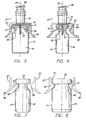
- FIG. 3 a side, cross-sectional view is seen of the adapter of the perspective views of FIGS. 1 and 2 .
- the piston element 45 has a hollow interior 53 that provides a fluid flow path completely through the needle-free valve 37 and into fluid communication with the lumen 55 of the sharpened cannula 33.
- the lumen 55 of the sharpened cannula 33 is in fluid communication with the openings 39 located at the sharpened tip of the cannula so that fluid communication can occur through the cannula 33.
- the view of FIG. 3 shows the vial adapter 21 unaccessed by a blunt cannula.
- the piston head 43 of the piston element 45 has a naturally open bore 47 that would permit fluid flow through the piston element when it is open.
- the bore 47 has been forced closed by the difference between it and the female Luer opening 57 in the female Luer connector 41.
- the piston head 43 is elliptical in shape and has a marquise-shaped bore 47.
- the size of the piston head 43 is selected so that when the piston head is constrained into the circular interior of the tapered opening 57 of the female Luer connector 41, the bore 47 is completely collapsed to tightly close off the fluid flow path 53.
- the adjacent lips 59 form a taper lip seal by abutting one another and applying further force to keep the bore closed when fluid pressure exists within the fluid flow path (interior) of the piston element when the valve is in its unaccessed state as shown in FIGS. 1 through 3 .
- the lips comprise conical sections that extend from the bore's sides to function as a seal.
- the angle of the taper is selected so that internal pressure existing in the valve when the piston is in the closed state would force the lips toward one another thereby holding the bore closed.
- the first end 25 of the housing 23 also includes a base 61 from whose center extends the sharpened cannula 33.
- the base also has a groove 63 in which is mounted the bellows portion 65 of the piston element.
- the piston element 45 includes a total of four bellows, although more or fewer may be found to be appropriate in other embodiments.
- the bellows portion 65 provides a spring force to bias the piston head 43 into the female Luer opening 57.
- the sharpened cannula 33 is disposed within the protective shroud 27 which is at least as long as the sharpened cannula 33 and surrounds the cannula to protect an operator of the adapter 21 from being punctured by the sharpened tip of the cannula 33.
- FIG. 3 shows only two claws, one from the first set of claws 29 and one from the second set of longer claws 31, formed at the inner periphery 67 of the shroud 27 surrounding the sharpened cannula 31.
- the claws are used as a means to retain and engage the mounted vial adapter 37 on a vial opening plugged with a rubber stopper and secured with an annular crimped retaining cap.
- the female Luer connector 41 also includes external threads 69 to which a complementary thread cuff of a male Luer connector may be engaged to firmly hold the two connectors together.
- FIG. 4 illustrates the application of the vial adapter 21 to a vial 71 having a closure 73.
- the sharpened cannula 33 will be moved through the opening 75 of the closure 73 and will be pressed through the rubber stopper 77 to establish fluid communication with the contents of the vial.
- the crimped retaining cap of the closure 73 covers the stopper 77, except for the opening 75, and is crimped around the bottom of the vial flange 79 as shown so that the stopper is held firmly in position in the vial.
- the opening 75 of the closure includes a perforated, tear-away or bend-away cover (not shown). The operator pries the perforated cover up from the opening, which breaks the tabs between the perforations, and removes it entirely.
- the drug vial 71 includes a body 81 connected to a neck 83 which defines a passage into the body of the vial 71 and terminates in an outwardly extending flange 79 that defines an opening 85 into the vial 71.
- the opening 85 of the vial is surrounded by the outwardly extending flange 79 thereby creating a convenient ledge to which the closure 73 may be crimped to firmly hold the stopper 77 in the vial's opening 85.
- each claw of the first set of claws 29 and of the second set of claws 31 has a terminal end 89 and the terminal ends of the first set of claws and the terminal ends of the second set of claws are located in a common plane indicated by the dashed line having the numeral 87 in this embodiment. In other embodiments, the terminal ends of the claws are not located in a common plane. Additionally, the first set of claws and the second set of claws alternate along the inner periphery 67 of the shroud 27.
- the shroud 27 in this embodiment is longer than the length of the sharpened cannula 33 and surrounds the sharpened cannula to protect an operator of the adapter 21 from being punctured by the sharpened tip of the cannula 33. Additionally, the shroud 27 is slotted to allow for selective bending outward to accept vial closures of larger sizes.
- the first step in using the vial adapter 21 is to place the end of the adapter including the sharpened cannula 33 surrounded by the shroud 27 next to the rubber stopper 77 of a vial 71.
- the vial adapter is manually pressed onto the closure 73 of the vial 71with force directed axially through the centerline 91 of the sharpened cannula 33 sufficient to drive the sharpened cannula 33 into and through the rubber stopper.
- the second set of hinged claws 31 will deform plastically during the mounting motion of the adapter to the vial and bend up to a vertical or near-vertical position approximately parallel with the centerline 91 of the vial as shown in FIG. 5 , and while the first set of shorter and rigid claws 29 will engage the larger vial closure.
- the bottom of the shroud 27 in this embodiment includes a flared portion 93 that assists in guiding the shroud 27 over the closure 73 of a vial.
- the flared portion extends beyond the sharpened tip of the cannula 33 to assist in guiding the shroud into the correct alignment with the vial closure before the sharpened tip 33 penetrates the closure.
- the first set of claws 29 having a shorter length are structured such that when the adapter is mounted on a vial with a vial closure of 20 mm ⁇ 3 mm, the first set of claws will engage and retain the adapter 21 in position on the vial as shown in FIG. 5 .
- the second set of longer hinged claws 31, used to engage vial closures of 13 mm ⁇ 4 mm plastically deform out of the way as shown in FIG. 5 . Plastic deformation of the second set of claws 31 occurs when the claws are bent beyond a certain stress point.
- the thickness of the second set of claws is selected so that when plastically deformed, the second set of claws do not apply a substantial force to the closure 73 that exceeds a selected diameter.
- the long claws 31 are plastically deformed as shown and do not exert relatively large pressure on the vial that may tend to expel the vial from the adapter. Instead, the deformed claws 31 exert little force against the retention of the vial closure and the vial within the adapter 21.
- the vial closure 73 is smaller as illustrated in FIG., 6 specifically in this embodiment, a closure that is 13 mm ⁇ 4 mm in diameter, the first set of claws 29 will not engage the closure device but the second set of claws 31 will.
- the vial adapter 21 is manually pressed onto the closure 73 of the vial 71 with force directed axially through the centerline 91 of the sharpened cannula 33, the second set of longer hinged claws 31 deform elastically during the mounting motion and snap under the crimped retaining cap 73 as shown in FIG. 6 .
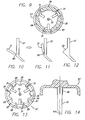
- FIGS. 7 and 8 present schematic views of the operation of the claws with vial closures 73 of different sizes.
- FIG. 7 schematically presents the operation of the second set of longer claws 31 engaging a smaller vial closure 73 while the first set of claws 29 remain disengaged.
- FIG. 8 primarily demonstrates the plastic deformation of the second set of claws 31 while mounting the vial adapter 21 to a vial that is too large for engagement by those larger claws 31. Instead, the shorter claws (first set) 29 engage the vial closure 73.
- FIG. 9 shows a partial view of the vial adapter shown in FIG. 3 along the lines indicated by the "9" numerals.
- a view of the inner periphery 67 of the shroud 27 is presented showing the alternating placement of the first set of shorter claws 29 with the second set of longer claws 31.
- the second set of claws 31 alternate with the first set of claws 29 about the inner periphery 67 such that each of the claws of the second set of claws is located between two claws of the first set. Because there are three claws in each set and they are spaced equally around the inner periphery 67 in this case, the claws in each set are therefore spaced at 120° from each other in the same set. However, in other embodiments, the claws may be spaced apart at different intervals.
- the centralized location of the sharpened cannula 33 is also apparent from FIG. 9 .
- FIGS. 10 and 11 show an enlarged view of a variation of the second set of claws 31 in which a narrowed segment 95 is included in each of the second set of claws to act as a hinge or plastic deformation point.
- FIG. 10 specifically shows the claw 31 in its normal, pre-mounting configuration prior to engagement with a vial closure.
- FIG. 11 shows the claw 31 of FIG. 10 in which the narrowed segment 95 has plastically deformed and the claw is permanently in a new "vertical" configuration due to the plastic deformation.
- plastic deformation of this claw 31 of the second set of claws has occurred during the mounting process of the vial adapter 21 on a larger vial closure, in this embodiment, a closure of approximately 20 mm in diameter.
- FIG. 12 presents an enlarged view of a claw 29 from the first set 27 of claws used to engage a vial closure with a larger diameter; e.g ., 20 mm.
- FIG. 13 illustrates an alternative embodiment of a circular array of claws 97 wherein the circular array of claws surrounding the sharpened cannula 33 is arranged about the inner periphery 67 of a shroud 27 such that multiples of the first set of shorter claws 29 alternate with one claw 31 from the second set of longer claws 31.
- the multiple shorter claws 29 have a serrated appearance and there are three shorter claws 29 between each pair of longer claws 31.
- the sharpened cannula 33 is shown with a protruding rib 99 located so that when the cannula is engaged with the rubber stopper of a vial closure, the protruding rib will resist rotation of the cannula once the sharpened cannula with the protruding rib have punctured the rubber stopper of the closure.
- the protruding rib 99 is elongated and is oriented parallel to a longitudinal axis 101 of the central sharpened cannula 33
- a plurality of protruding ribs 99 are formed on the sharpened cannula 33 and will resist rotation of the cannula.
- FIG. 15 is a view similar to FIG. 3 except the needle-free valve 37 has been accessed by a male Luer connector 103 thereby pressing the piston element 45 further into the valve housing 23 and compressing the spring bellows section 65.
- the bore 47 of the resilient piston element 45 has returned to its naturally open position to permit fluid flow through the needle-fee valve and through the lumen 55 of the sharp cannula 33 to establish a fluid flow path through the vial adapter.
- FIGS. 16 and 17 provide further details of the piston element 45 disclosed and discussed above.
- the bellows section 65 in these figures has more bellows than the piston element disclosed previously; however, the piston element operates the same as discussed above in regard to FIGS. 3 and 15 .
- the elliptical shape of the piston head 43 with the marquise-shaped, naturally open bore 47 is visible.
- a versatile vial adapter has been disclosed.
- the design of the adapter is such that an operator of the adapter is protected from inadvertent punctures by the cannula by a shroud, yet the adapter can easily be used to adapt pierceable septa to use with needle-free devices. Both a sharpened cannula and a needle-free resealable site are included in one adapter thus obviating the need for two separate adapters.
- the adapter also reduces the need to stock as many different sizes of adapters, as the adapter in accordance to the invention is capable of fitting multiple vial closures.
Abstract
an adapter housing (23) having a first end (25) comprising a slotted shroud (27) with an inner periphery and a circular array of claws (28) extending radially inward from the periphery, and a second end (35); the adapter housing having a thickness at the inner periphery;
the first end (25) including a base, a central sharpened cannula (33) extending from the base to perforate a vial's rubber stopper and provide fluid communication between the vial and the first end, wherein said circular array of claws (28) are oriented radially inwardly towards said sharpened cannula;
wherein the circular array of claws comprises:
a first set of rigid claws (29) having a first length
a second set of hinged claws (31), each of which has a second length that is longer than the first length of the first set of claws, each of the second set of claws adapted to deflect and plastically deform when the adapter is placed over a closure exceeding a selected first diameter, thereby permitting the second set of claws to accommodate the larger closure size; and
a resealable needle-free valve located at the second end of the adapter housing that opens to permit fluid flow upon insertion of a blunt cannula and closes to prevent fluid flow upon removal of such blunt cannula.
Description
- The invention relates generally to connectors of the type used in the handling and administration of parenteral fluids, and more particularly, to a vial adapter having a sharp cannula for piercing a vial closure, a shroud protecting an operator from inadvertent puncture by the sharp cannula, and a valved connector opposite the sharp cannula for connection to another device for fluid flow.
- Access ports for injecting fluid into or removing fluid from a system, such as a drug vial, are well known and widely used. Conventional injection sites in drug vials generally involve a pierceable rubber stopper formed of an elastomeric material such as butyl rubber or the like, placed in the opening of the vial. A closure, typically formed of metal, is crimped over the rubber stopper and the flange of the vial to positively hold the stopper in place in the opening of the vial. The closure has an outer size, known as a "finish size." The closure also has an opening, or access port, through which the stopper and the vial opening may be accessed. A sharp cannula is inserted into the access port piercing the rubber stopper to position the distal, open end of the cannula past the rubber stopper to make fluid connection with the interior of the vial.
- Adapters have been found useful in that they can adapt the sharpened cannula that is placed into fluid communication with the vial to the connection device of another fluid container or fluid conduction device. For example, the adapter may include a female Luer fitting opposite the sharpened cannula to receive the nozzle of a syringe. The "adapter" therefore adapts the vial to the syringe, or adapts the sharpened cannula to the Luer-shaped nozzle of the syringe.
- It has also been found useful to provide a means to attach or anchor the adapter to the vial to hold it in place while fluid communication between the vial and another device proceeds so that inadvertent disengagement of the adapter from the vial does not occur. For example, the adapter may have two arms that engage the neck or flange of the vial and hold the adapter in place on the vial. Other means include a shroud that fits around the outside of the vial closure and snaps onto the vial closure under the crimped retaining cap thereby grasping the vial neck flange and the underside of the closure.
- It has also been found useful to have a valve placed in the adapter. The valved adapter permits engagement of the sharpened cannula with the contents of the vial without leakage of fluid from the vial through the adapter. Then when the second fluid device has been prepared, it can be connected to the adapter thereby activating the valve that then permits fluid flow between the vial and second device. One approach used today is to have two parts to result in a valved vial adapter. The vial adapter includes a sharpened cannula to pierce the stopper of a vial, and the other end of the adapter includes a female Luer connector. At the female Luer connector, a valve device having a male connector at one end is attached. While the vial adapter is then "valved," two parts were necessary to do so. It would be desirable to have a single part that not only adapts the vial to a blunt cannula, but one that also interposes a valve in between. Manufacturers of such medical devices strive for effective and reliable devices yet desire to keep costs as low as possible.
- However, some of the existing adapters available today suffer from various shortcomings. For example, most adapters are designed to function only on a single vial closure finish size. These adapters do not securely attach to vial closures with diameters smaller or larger than vial closure finish sizes they are primarily molded to fit. They are therefore not usable on vials of other sizes. In addition, some vial adapters do not adequately protect an operator from inadvertent puncture of the operator's skin by the sharpened cannula of the adapter. The shroud or vial engagement device does not extend completely over the sharpened cannula, thus exposing operators to possible puncture.
- Accompanying this limitation of functioning with only a single size of vial, a further consideration is the expense to hospitals or other medical facilities caused by having to stock numerous types and sizes of adapters. Vials of many flange sizes and closure sizes are available and are frequently found in medical care facilities. Typically a hospital must stock a variety of adapters to be assured of having the correct adapter available that will properly interconnect with the multiple vial closures that exist. If a hospital must maintain a stock of adapters for each possible size of closure, a logistical problem as well as increased expense can result. Two common sizes of vial closures are 13 mm vial closures and 20 mm vial closures. Reducing the number of adapters that must be stocked in a hospital can significantly lessen the problems with stocking the correct sizes and can reduce expenses.
- It has also been a trend in recent years to provide needle-free valve devices in an effort to lower the risk of inadvertent punctures of health care personnel by sharpened devices. More recently, connectors or adapters for accommodating the injection and withdrawal of fluids without the use of sharp cannulas have been put to use in increasing numbers. This is due, at least in part, to concern regarding the possibility of the transmission of blood-borne diseases through accidental needle punctures of persons handling the sharp cannulas. Connectors having as few sharpened surfaces as possible are desirable because such hazard is thereby lessened.
- Furthermore, it is desirable that needle-fee connectors be configured so that they can be easily cleaned by an antiseptic wipe, or otherwise sterilized, prior to making a connection. All exterior surfaces that may be involved in the transmission of fluid should be readily available for cleaning prior to the connection being made. Some prior connectors have a small rift or fissure defined by a clearance between parts. Such a feature is difficult and inconvenient to clean in attempting to sterilize a connector. Alternatively, connectors requiring a cap to maintain a sterile connection port prior to use are undesirable because the extra steps involved in removing and replacing a cap are inconvenient, while the manufacture of the cap adds expense.
- Thus it would be desirable to provide a needle-free connector as part of the valve that is included in the adapter discussed above. This approach would increase safety for medical personnel who handle the adapter.
- Although certain vial adapters exist that can accommodate multiple sizes of vial closure finishes, a practical way to accommodate the large vial finish sizes is needed. Where a vial adapter is used to connect to both large and small vial finish sizes, the arms used for the small finish sizes must move out of the way when a large finish size must be accommodated. Arms that merely bend out of the way in such an application of the adapter can still exert relatively large pressure on the vial and tend to expel the vial from the adapter. Thus the small arms of such adapters work to retain the adapter to the vial while the longer arms work to separate the adapter from the vial. As is obvious, such an arrangement is undesirable. It is also undesirable to provide large arms that simply break away when encountering large finish sizes as then there would be small loose plastic parts that are not controlled. On the other hand, attempting to design break-away arms can increase expense as the arms must be designed to withstand a certain amount of force with the small vial finish sizes yet break away with the large vial finish sizes.
- Hence, those concerned with the development of medical adapters have recognized the need for a single adapter that is usable with vials of different sizes. There has also been recognized a need for a protection device to be located around the sharpened cannula of such an adapter to protect operators from inadvertent punctures of their skin. Further, a need has been recognized for an adapter that can interconnect a vial with another fluid flow device by means of a needle-free valve so that sharpened needles are not needed that may also cause inadvertent needle punctures of operators. Further, a need has been recognized for a valve that is integral to the vial adapter. The invention fulfills these needs and others.
- Briefly and in general terms, the invention is directed to a vial adapter for interconnecting with sealed vial closures of different diameters. In one main aspect, a vial adapter in accordance with the invention comprises a housing having a first end with an inner periphery with a circular array of claws, and having a second end, the housing having a thickness at the inner periphery and a sharpened cannula extending from the first end of the housing for penetrating a seal of a vial closure to establish fluid communication between the vial and the first end, wherein the array of claws comprises a first set of claws extending radially inwardly from the inner periphery, each of which has a first length, and a second set of claws extending radially inwardly from the inner periphery, each of the second set of claws having a second length that is longer than the first length of the first set of claws, each of the second set of claws adapted such that when the vial adapter is placed over a closure exceeding a selected diameter, each of the second set of claws will deflect and plastically deform thereby permitting the second set of claws to accommodate the larger closure. The length of each of the first set of claws is selected to engage a larger diameter vial closure and the length of each of the second set of claws is selected to engage a smaller diameter vial closure.
- In further aspects, the second set of claws are thinner than the housing at the inner periphery and plastic deformation of the second set of claws occurs at or near the location at which the second set of claws are joined to the inner periphery. Further, the thickness of the second set of claws is selected so that when plastically deformed, the second set of claws do not apply a substantial force to the closure which may tend to decouple the vial adapter from the vial closure and the vial. In yet another aspect, the second set of claws comprises a narrowed segment at which the plastic deformation takes place.
- In other aspects, the length of each of the second set of claws is selected such that when the adapter engages a smaller diameter vial closure, each of the second set of claws deforms elastically to engage the smaller vial closure. Further, the second set of claws deflect elastically as a result of a force directed axially through the center line of the vial adapter so that the second set of claws will snap under a crimped retaining cap surrounding a rubber stopper placed in the opening of the vial. In more detail, the second set of claws are located at the inner periphery so that they are alternating with the first set of claws about the inner periphery.
- In more detailed aspects, the adapter housing further comprises a shroud forming a part of the adapter housing at the first end, the shroud extending from the first end far enough to surround the sharpened portion of the sharpened cannula to protect an operator of the vial adapter from inadvertent puncture by the sharpened cannula. The cannula comprises a protruding rib located so that when the cannula is engaged with the rubber stopper of a vial closure, the protruding rib resists rotation of the cannula once the sharpened cannula with the protruding rib have punctured the rubber stopper of the closure. The protruding rib is elongated and oriented parallel to a longitudinal axis of the central cannula. In another aspect, the cannula comprises a plurality of protruding ribs elongated and oriented parallel to a longitudinal axis of the central cannula.
- In another detailed alternate aspect, each of the first set of claws has a terminal end and each of the second set of claws has terminal end and the terminal ends of the first set of claws and the terminal ends of the second set of claws are located in a common plane.
- In yet further detailed aspects, a resealable needle-free valve is located in the second end of the adapter housing, wherein the needle-free valve opens to permit fluid flow upon insertion of a blunt cannula and closes to prevent fluid flow upon removal of such blunt cannula. The resealable needle-free valve comprises a valve housing within which is disposed a deformable piston element that provides a fluid flow path through its interior, the piston element having a naturally open bore wherein the bore is closed to prevent fluid flow when the needle-free valve is not accessed and wherein the bore opens to its naturally open shape to permit fluid flow when the valve is accessed. Yet further, the valve housing comprises a connection port, an exit orifice, a first section of a first cross-sectional size disposed adjacent the connection port, and a second section of a second cross-sectional size that is larger than the first section and the piston element comprises a deformable piston head in which the bore is formed, the piston head being movable from the first section of the housing as the needle-free valve is accessed and movable to the second section of the housing when the needle-free valve is not accessed, the first section having a size that deforms the piston head so as to occlude the bore, the second section having a size that allows the piston head to assume its natural shape in which the bore is open to provide a fluid flow path between the connection port and the exit orifice. In yet more aspects, the housing of the resealable needle-free valve comprises a connection port and an exit orifice and when the needle-free valve is accessed, the interior of the deformable piston element provides the fluid flow path through the needle-free valve between the connection port and the exit orifice.
- Other features and advantages of the present invention will become apparent from the following detailed description of preferred embodiments which, taken in conjunction with the accompanying drawings, illustrate by way of example the principles of the invention.
-
-
FIGURE 1 is a perspective view of a vial adapter in accordance with principles of the present invention looking at the adapter from the sharpened cannula angle, the adapter having a Luer adapter with a needle-free site at one end, a shroud surrounding the sharpened cannula at the opposite end and a circular array of claws disposed at the inner periphery of the shroud and oriented radially inwardly toward the sharpened cannula for attaching to a vial closure which the sharpened cannula would perforate; -
FIG. 2 is a top perspective view of the vial adapter inFIG. 1 looking at the adapter from the needle-free valve angle, and illustrating, in particular, the resealable needle-free site located at the female Luer adapter portion of the housing, and also showing the piston component of the needle-free valve portion of the adapter; -
FIG. 3 is a cross-sectional view of the adapter ofFIGS. 1 and 2 showing the adapter in its closed or inactivated state with the inactivated resealable needle-free site at one end, with a piston component in the interior of its housing, and a sharpened cannula at the opposite end surrounded by a slotted shroud with a partial view of a claw from the first set of claws and a hinged claw of the second set of claws respectively; -
FIG. 4 is a partially broken away side view of the adapter with the shroud partially cut away and ready to be attached to a vial having a 20 mm closure; -
FIG. 5 is a partially broken away side view of the vial adapter attached to the vial having a 20 mm closure ofFIG. 4 , with the sharpened cannula penetrating the vial's stopper so that fluid communication with the vial is established; -
FIG. 6 is a partially broken away side view of the vial adapter fully attached to a vial having a 13 mm closure, with the second set of hinged claws with the hinge structure engaging the 13 mm closure and the sharpened cannula penetrating the vial's stopper; -
FIG. 7 is a non-cross sectional view ofFIG. 6 showing the longer claw from the second set engaging the neck of the vial and the smaller vial closure while a claw from the first set of shorter claws is disengaged; -
FIG. 8 is a non-cross sectional view ofFIG. 5 showing a longer claw from the second set plastically deformed at the narrowed hinge and a claw from the first set engaging the neck of the vial and the larger vial closure; -
FIG. 9 is an end on view of the vial adapter ofFIG. 1 from the sharpened cannula end, illustrating in particular the circular array of first set of claws alternating with the second set of longer claws and also showing the slotted shroud. InFIG. 9 , each long claw is positioned between two short claws; -
FIG. 10 is an enlarged detailed view of a hinged claw from the second set of claws inFIG 9 ; -
FIG. 11 is an enlarged detailed view of the hinged claw inFIG. 10 , specifically illustrating the plastic deformation that takes place at the hinge when the adapter engages a large vial closure; -
FIG. 12 is an enlarged detailed view of a claw from the first set of claws inFIG. 9 ; -
FIG. 13 illustrates an end on view of an alternative embodiment of the vial adapter ofFIG. 9 , illustrating in particular a different arrangement of the circular array of claws in which there are two shorter claws positioned between each long claw; -
FIG. 14 is an enlarged detailed view of the sharpened cannula in an alternate embodiment, illustrating in particular the protruding ribs extending from the base of the sharpened cannula that resist rotation of the cannula once they have penetrated the stopper of a vial; -
FIG. 15 is a view similar toFIG. 3 except the valve has been accessed by a male Luer connector and in response, the internal resilient piston has returned to its naturally open position to permit fluid flow through the adapter; -
FIGS. 16 and 17 present views of a piston element usable in the needle-free valve of the vial adapter disclosed, showing the elliptical shape of the piston head with the marquise-shaped, naturally open bore. - As shown in the drawings for purposes of illustration wherein like reference numerals designate corresponding or like elements among the several views, there is shown in the bottom perspective view of
FIG. 1 avial adapter 21 having ahousing 23 with afirst end 25 that includes ashroud 27 with a circular array ofclaws 28 surrounding a sharpenedcannula 33, and asecond end 35 that includes a resealable needle-free valve 37. Details of the resealable needle-free valve 37 are provided inU.S. Patent No. 5,676,346 to Leinsing entitled NEEDLELESS CONNECTOR VALVE, issued on October 14, 1997 and incorporated herein by reference, although the valve is discussed generally below. InFIG. 1 , the circular array of claws can be seen to include multipleshort claws 29 and long claws 31 (only one of each is indicated by the respective numeral to preserve the clarity of the drawing). It should be noted that the sharpenedcannula 33 includesopenings 39 through which fluid may be communicated. - Referring now to the top perspective view of
FIG. 2 , the needle-free valve 37 can be more clearly seen. At thesecond end 35, the resealable needle-free valve 37 includes afemale Luer connector 41. TheLuer connector 41 is configured to receive all ANSI standard male Luer fittings, as well as other blunt cannulas or fluid conduit devices. Thepiston head 43 of adeformable piston element 45 can also be seen that has a naturallyopen bore 47, which in this case has been closed to prevent fluid flow through the adapter. Thepiston element 45 is, in this embodiment, located within avalve housing 49 that comprises a transparenttubular body portion 51 and thefemale Luer connector 41, which in this embodiment is opaque, mounted to thebody portion 51. - Turning now also to
FIG. 3 , a side, cross-sectional view is seen of the adapter of the perspective views ofFIGS. 1 and 2 . Thepiston element 45 has ahollow interior 53 that provides a fluid flow path completely through the needle-free valve 37 and into fluid communication with thelumen 55 of the sharpenedcannula 33. Thelumen 55 of the sharpenedcannula 33 is in fluid communication with theopenings 39 located at the sharpened tip of the cannula so that fluid communication can occur through thecannula 33. The view ofFIG. 3 shows thevial adapter 21 unaccessed by a blunt cannula. However, thepiston head 43 of thepiston element 45 has a naturally open bore 47 that would permit fluid flow through the piston element when it is open. In the configuration ofFIGS. 1, 2, and 3 , thebore 47 has been forced closed by the difference between it and the female Luer opening 57 in thefemale Luer connector 41. More particularly, thepiston head 43 is elliptical in shape and has a marquise-shapedbore 47. The size of thepiston head 43 is selected so that when the piston head is constrained into the circular interior of the taperedopening 57 of thefemale Luer connector 41, thebore 47 is completely collapsed to tightly close off thefluid flow path 53. Theadjacent lips 59 form a taper lip seal by abutting one another and applying further force to keep the bore closed when fluid pressure exists within the fluid flow path (interior) of the piston element when the valve is in its unaccessed state as shown inFIGS. 1 through 3 . The lips comprise conical sections that extend from the bore's sides to function as a seal. The angle of the taper is selected so that internal pressure existing in the valve when the piston is in the closed state would force the lips toward one another thereby holding the bore closed. - The
first end 25 of thehousing 23 also includes a base 61 from whose center extends the sharpenedcannula 33. The base also has agroove 63 in which is mounted thebellows portion 65 of the piston element. In this embodiment, thepiston element 45 includes a total of four bellows, although more or fewer may be found to be appropriate in other embodiments. Thebellows portion 65 provides a spring force to bias thepiston head 43 into thefemale Luer opening 57. - The sharpened
cannula 33 is disposed within theprotective shroud 27 which is at least as long as the sharpenedcannula 33 and surrounds the cannula to protect an operator of theadapter 21 from being punctured by the sharpened tip of thecannula 33. Furthermore, for simplicity,FIG. 3 shows only two claws, one from the first set ofclaws 29 and one from the second set oflonger claws 31, formed at theinner periphery 67 of theshroud 27 surrounding the sharpenedcannula 31. As is described in further detail below, and shown in other drawings, the claws are used as a means to retain and engage the mountedvial adapter 37 on a vial opening plugged with a rubber stopper and secured with an annular crimped retaining cap. - The
female Luer connector 41 also includesexternal threads 69 to which a complementary thread cuff of a male Luer connector may be engaged to firmly hold the two connectors together. -
FIG. 4 illustrates the application of thevial adapter 21 to avial 71 having aclosure 73. The sharpenedcannula 33 will be moved through theopening 75 of theclosure 73 and will be pressed through therubber stopper 77 to establish fluid communication with the contents of the vial. The crimped retaining cap of theclosure 73 covers thestopper 77, except for theopening 75, and is crimped around the bottom of thevial flange 79 as shown so that the stopper is held firmly in position in the vial. In some cases, theopening 75 of the closure includes a perforated, tear-away or bend-away cover (not shown). The operator pries the perforated cover up from the opening, which breaks the tabs between the perforations, and removes it entirely. - In more detail in regard to
FIG. 4 , thedrug vial 71 includes abody 81 connected to aneck 83 which defines a passage into the body of thevial 71 and terminates in an outwardly extendingflange 79 that defines anopening 85 into thevial 71. Thus, theopening 85 of the vial is surrounded by the outwardly extendingflange 79 thereby creating a convenient ledge to which theclosure 73 may be crimped to firmly hold thestopper 77 in the vial'sopening 85. - Continuing to refer to
FIG. 4 , each claw of the first set ofclaws 29 and of the second set ofclaws 31 has aterminal end 89 and the terminal ends of the first set of claws and the terminal ends of the second set of claws are located in a common plane indicated by the dashed line having the numeral 87 in this embodiment. In other embodiments, the terminal ends of the claws are not located in a common plane. Additionally, the first set of claws and the second set of claws alternate along theinner periphery 67 of theshroud 27. - Referring now to
FIGS. 1, 2, and 4 , theshroud 27 in this embodiment is longer than the length of the sharpenedcannula 33 and surrounds the sharpened cannula to protect an operator of theadapter 21 from being punctured by the sharpened tip of thecannula 33. Additionally, theshroud 27 is slotted to allow for selective bending outward to accept vial closures of larger sizes. - Referring particularly now to
FIG. 5 , the first step in using thevial adapter 21 is to place the end of the adapter including the sharpenedcannula 33 surrounded by theshroud 27 next to therubber stopper 77 of avial 71. Next the vial adapter is manually pressed onto theclosure 73 of the vial 71with force directed axially through thecenterline 91 of the sharpenedcannula 33 sufficient to drive the sharpenedcannula 33 into and through the rubber stopper. If the diameter of the vial closure is relatively large, for example 20 mm or greater, the second set of hingedclaws 31 will deform plastically during the mounting motion of the adapter to the vial and bend up to a vertical or near-vertical position approximately parallel with thecenterline 91 of the vial as shown inFIG. 5 , and while the first set of shorter andrigid claws 29 will engage the larger vial closure. - The bottom of the
shroud 27 in this embodiment includes a flaredportion 93 that assists in guiding theshroud 27 over theclosure 73 of a vial. In the embodiment shown, the flared portion extends beyond the sharpened tip of thecannula 33 to assist in guiding the shroud into the correct alignment with the vial closure before the sharpenedtip 33 penetrates the closure. - In one embodiment, the first set of
claws 29 having a shorter length are structured such that when the adapter is mounted on a vial with a vial closure of 20 mm ± 3 mm, the first set of claws will engage and retain theadapter 21 in position on the vial as shown inFIG. 5 . During the engagement of the first set ofclaws 27 to the vial closure, the second set of longer hingedclaws 31, used to engage vial closures of 13 mm ± 4 mm, plastically deform out of the way as shown inFIG. 5 . Plastic deformation of the second set ofclaws 31 occurs when the claws are bent beyond a certain stress point. Further, the thickness of the second set of claws is selected so that when plastically deformed, the second set of claws do not apply a substantial force to theclosure 73 that exceeds a selected diameter. Thus in the case shown inFIG. 5 , thelong claws 31 are plastically deformed as shown and do not exert relatively large pressure on the vial that may tend to expel the vial from the adapter. Instead, thedeformed claws 31 exert little force against the retention of the vial closure and the vial within theadapter 21. - If the
vial closure 73 is smaller as illustrated inFIG., 6 specifically in this embodiment, a closure that is 13 mm ± 4 mm in diameter, the first set ofclaws 29 will not engage the closure device but the second set ofclaws 31 will. As thevial adapter 21 is manually pressed onto theclosure 73 of thevial 71 with force directed axially through thecenterline 91 of the sharpenedcannula 33, the second set of longer hingedclaws 31 deform elastically during the mounting motion and snap under the crimped retainingcap 73 as shown inFIG. 6 . -
FIGS. 7 and 8 present schematic views of the operation of the claws withvial closures 73 of different sizes.FIG. 7 schematically presents the operation of the second set oflonger claws 31 engaging asmaller vial closure 73 while the first set ofclaws 29 remain disengaged.FIG. 8 primarily demonstrates the plastic deformation of the second set ofclaws 31 while mounting thevial adapter 21 to a vial that is too large for engagement by thoselarger claws 31. Instead, the shorter claws (first set) 29 engage thevial closure 73. -
FIG. 9 shows a partial view of the vial adapter shown inFIG. 3 along the lines indicated by the "9" numerals. A view of theinner periphery 67 of theshroud 27 is presented showing the alternating placement of the first set ofshorter claws 29 with the second set oflonger claws 31. In the view ofFIG. 9 , the second set ofclaws 31 alternate with the first set ofclaws 29 about theinner periphery 67 such that each of the claws of the second set of claws is located between two claws of the first set. Because there are three claws in each set and they are spaced equally around theinner periphery 67 in this case, the claws in each set are therefore spaced at 120° from each other in the same set. However, in other embodiments, the claws may be spaced apart at different intervals. The centralized location of the sharpenedcannula 33 is also apparent fromFIG. 9 . -
FIGS. 10 and 11 show an enlarged view of a variation of the second set ofclaws 31 in which a narrowedsegment 95 is included in each of the second set of claws to act as a hinge or plastic deformation point.FIG. 10 specifically shows theclaw 31 in its normal, pre-mounting configuration prior to engagement with a vial closure. However,FIG. 11 shows theclaw 31 ofFIG. 10 in which the narrowedsegment 95 has plastically deformed and the claw is permanently in a new "vertical" configuration due to the plastic deformation. RelatingFIG. 11 to FIG. 8 , plastic deformation of thisclaw 31 of the second set of claws has occurred during the mounting process of thevial adapter 21 on a larger vial closure, in this embodiment, a closure of approximately 20 mm in diameter. -
FIG. 12 presents an enlarged view of aclaw 29 from thefirst set 27 of claws used to engage a vial closure with a larger diameter; e.g., 20 mm. -
FIG. 13 illustrates an alternative embodiment of a circular array ofclaws 97 wherein the circular array of claws surrounding the sharpenedcannula 33 is arranged about theinner periphery 67 of ashroud 27 such that multiples of the first set ofshorter claws 29 alternate with oneclaw 31 from the second set oflonger claws 31. In this embodiment, the multipleshorter claws 29 have a serrated appearance and there are threeshorter claws 29 between each pair oflonger claws 31. - Turning now to
FIG. 14 , the sharpenedcannula 33 is shown with a protrudingrib 99 located so that when the cannula is engaged with the rubber stopper of a vial closure, the protruding rib will resist rotation of the cannula once the sharpened cannula with the protruding rib have punctured the rubber stopper of the closure. As shown, the protrudingrib 99 is elongated and is oriented parallel to alongitudinal axis 101 of the central sharpenedcannula 33 In the embodiment show, a plurality of protrudingribs 99 are formed on the sharpenedcannula 33 and will resist rotation of the cannula. -
FIG. 15 is a view similar toFIG. 3 except the needle-free valve 37 has been accessed by amale Luer connector 103 thereby pressing thepiston element 45 further into thevalve housing 23 and compressing the spring bellowssection 65. In response, thebore 47 of theresilient piston element 45 has returned to its naturally open position to permit fluid flow through the needle-fee valve and through thelumen 55 of thesharp cannula 33 to establish a fluid flow path through the vial adapter. -
FIGS. 16 and 17 provide further details of thepiston element 45 disclosed and discussed above. Thebellows section 65 in these figures has more bellows than the piston element disclosed previously; however, the piston element operates the same as discussed above in regard toFIGS. 3 and15 . The elliptical shape of thepiston head 43 with the marquise-shaped, naturallyopen bore 47 is visible. - Thus it will be appreciated that a versatile vial adapter has been disclosed. The design of the adapter is such that an operator of the adapter is protected from inadvertent punctures by the cannula by a shroud, yet the adapter can easily be used to adapt pierceable septa to use with needle-free devices. Both a sharpened cannula and a needle-free resealable site are included in one adapter thus obviating the need for two separate adapters. The adapter also reduces the need to stock as many different sizes of adapters, as the adapter in accordance to the invention is capable of fitting multiple vial closures.
- While particular forms of the invention have been illustrated and described, it will also be apparent to those stalled in the art that various modifications can be made without departing from the spirit and scope of the invention. Accordingly, it is not intended that the invention be limited except by the appended claims.
- Generally, the present application discloses the following concepts:
- Concept 1. A vial adapter for interconnecting with vial closures of different diameters, each closure having a seal, comprising: an adapter housing having a first end with an inner periphery with a circular array of claws, and having a second end, the housing having a thickness at the inner periphery; and a sharpened cannula extending from the first end of the adapter housing for penetrating a seal of a vial closure to establish fluid communication between the vial and the first end; wherein the array of claws comprises: a first set of claws extending radially inwardly from the inner periphery, each of which has a first length; and a second set of claws extending radially inwardly from the inner periphery, each of the second set of claws having a second length that is longer than the first length of the first set of claws, each of the second set of claws adapted such that when the vial adapter is placed over a closure exceeding a selected diameter, each of the second set of claws will deflect and plastically deform thereby permitting the second set of claws to accommodate the larger closure.
- Concept 2. The vial adapter of concept 1 wherein the length of each of the first set of claws is selected to engage a larger diameter vial closure.
- Concept 3. The vial adapter of concept 1 wherein the length of each of the second set of claws is selected to engage a smaller diameter vial closure.
- Concept 4. The vial adapter of concept 1 wherein the second set of claws are thinner than the adapter housing at the inner periphery and plastic deformation of the second set of claws occurs at a location along the length of the thinner second claws.
- Concept 5. The vial adapter of concept 4 wherein the thickness of the second set of claws is selected so that when plastically deformed, the second set of claws do not apply a substantial force to the closure which may tend to decouple the vial adapter from the closure.
- Concept 6. The vial adapter of concept 1 wherein the second set of claws comprises a narrowed segment at which the plastic deformation takes place.
-
Concept 7. The vial adapter of concept 1 wherein the length of each of the second set of claws is selected such that when the adapter engages a smaller diameter vial closure, each of the second set of claws deforms elastically to engage the smaller vial closure. - Concept 8. The vial adapter of
concept 7 wherein the second set of claws deflect elastically as a result of a force directed axially through the center line of the vial adapter so that the second set of claws will snap under a crimped retaining cap surrounding a rubber stopper placed in the opening of the vial. -
Concept 9. The vial adapter of concept 1 wherein the second set of claws are located at the inner periphery so that they are alternating with the first set of claws about the inner periphery. - Concept 10. The vial adapter of concept 1 wherein the adapter housing further comprises a shroud forming a part of the adapter housing at the first end, the shroud extending from the first end far enough to surround the sharpened portion of the sharpened cannula to protect an operator of the vial adapter from inadvertent puncture by the sharpened cannula.
- Concept 11. The vial adapter of concept 1 wherein the cannula comprises a protruding rib located so that when the cannula is engaged with the rubber stopper of a vial closure, the protruding rib resists rotation of the cannula once the sharpened cannula with the protruding rib have punctured the rubber stopper of the closure.
- Concept 12. The vial adapter of concept 11 wherein the protruding rib is elongated and oriented parallel to a longitudinal axis of the central cannula.
- Concept 13. The vial adapter of concept 11 wherein the cannula comprises a plurality of protruding ribs elongated and oriented parallel to a longitudinal axis of the central cannula.
- Concept 14. The vial adapter of concept 1 wherein each of the first set of claws has a terminal end and each of the second set of claws has terminal end and the terminal ends of the first set of claws and the terminal ends of the second set of claws are located in a common plane.
- Concept 15. The vial adapter of concept 1 further comprising a resealable needle-free valve located in the second end of the adapter housing, wherein the needle-free valve opens to permit fluid flow upon insertion of a blunt cannula and closes to prevent fluid flow upon removal of such blunt cannula.
- Concept 16. The vial adapter of concept 15 wherein the resealable needle-free valve comprises a valve housing within which is disposed a deformable piston element that provides a fluid flow path through its interior, the piston element having a naturally open bore wherein the bore is closed to prevent fluid flow when the needle-free valve is not accessed and wherein the bore opens to its naturally open shape to permit fluid flow when the valve is accessed.
- Concept 17. The vial adapter of concept 16 wherein: the housing of the resealable needle-free valve comprises a connection port, an exit orifice, a first section of a first cross-sectional size disposed adjacent the connection port, and a second section of a second cross-sectional size that is larger than the first section; and the piston element comprises a deformable piston head in which the bore is formed, the piston head being movable from the first section of the valve housing as the needle-free valve is accessed and movable to the second section of the valve housing when the needle-free valve is not accessed, the first section having a size that deforms the piston head so as to occlude the bore, the second section having a size that allows the piston head to assume its natural shape in which the bore is open to provide a fluid flow path between the connection port and the exit orifice.
- Concept 18. The vial adapter of concept 16 wherein: the housing of the resealable needle-free valve comprises a connection port and an exit orifice; and when the needle-free valve is accessed, the interior of the deformable piston element provides the fluid flow path through the needle-free valve between the connection port and the exit orifice.
- Concept 19. A vial adapter for interconnecting with drug vial closures of different diameters, each closure having a seal, the vial adapter comprising: an adapter housing having a first end with an inner periphery and a circular array of claws extending radially inward from the periphery, and a second end, the adapter housing having a thickness at the inner periphery; the first end including a base, a central cannula extending from the base; a sharpened cannula located at the first end to perforate a vial's rubber stopper and provide fluid communication between the vial and the first end; wherein the circular array of claws comprises a first set of claws, each of which has a first length; wherein the circular array of claws comprises a second set of claws, each of which has a second length that is longer than the first length of the first set of claws, each of the second set of claws adapted to deflect and plastically deform when the adapter is placed over a closure exceeding a selected diameter, thereby permitting the second set of claws to accommodate the larger closure size; and a resealable needle-free valve located at the second end of the body that opens to permit fluid flow upon insertion of a blunt cannula and closes to prevent fluid flow upon removal of such blunt cannula.
- Concept 20. The vial adapter of concept 19 wherein the length of each of the first set of claws is selected to engage a larger diameter vial closure.
-
Concept 21. The vial adapter of concept 19 wherein the length of each of the second set of claws is selected to engage a smaller diameter vial closure. - Concept 22. The vial adapter of concept 19 wherein the second set of claws are thinner than the inner periphery and plastic deformation of the second set of claws occurs at a location along the length of the thinner second claws.
-
Concept 23. The vial adapter of concept 19 wherein each of the second set of claws comprises a narrowed segment at which the plastic deformation takes place. - Concept 24. The vial adapter of concept 19 wherein the length of each of the second set of claws is selected such that when the adapter engages a smaller diameter vial closure, each of the second set of claws deforms elastically to engage the smaller vial closure.
-
Concept 25. The vial adapter of concept 24 wherein the second set of claws deflect elastically as a result of a force directed axially through the center line of the vial adapter and the claws snap under the vial cap. - Concept 26. The vial adapter of concept 19 wherein each of the second set of claws is located at the periphery such that they are alternating with the first set of claws.
-
Concept 27. The vial adapter of concept 19 wherein the adapter housing further comprises a shroud forming a part of the housing at the first end, the shroud extending from the first end far enough to surround the sharpened portion of the sharpened cannula to protect an operator of the vial adapter from inadvertent puncture by the sharpened cannula. -
Concept 28. The vial adapter of concept 19 wherein the cannula comprises a protruding rib located so that when the cannula is engaged with the rubber stopper of a vial closure, the protruding rib resists rotation of the cannula once the sharpened cannula with the protruding rib have punctured the rubber stopper of the closure. -
Concept 29. The vial adapter ofconcept 28 wherein the protruding rib is elongated and oriented parallel to a longitudinal axis of the central cannula. - Concept 30. The vial adapter of
concept 28 wherein the cannula comprises a plurality of protruding ribs elongated and oriented parallel to a longitudinal axis of the central cannula. -
Concept 31. The vial adapter of concept 19 further comprising a resealable needle-free valve located in the second end of the adapter housing, wherein the needle-free valve opens to permit fluid flow upon insertion of a blunt cannula and closes to prevent fluid flow upon removal of such blunt cannula. - Concept 32. The vial adapter of
concept 31 wherein the resealable needle-free valve comprises a valve housing within which is disposed a deformable piston element that provides a fluid flow path through its interior, the piston element having a naturally open bore wherein the bore is closed to prevent fluid flow when the needle-free valve is not accessed and wherein the bore opens to its naturally open shape to permit fluid flow when the valve is accessed. -
Concept 33. The vial adapter of concept 32 wherein: the housing of the resealable needle-free valve comprises a connection port, an exit orifice, a first section of a first cross-sectional size disposed adjacent the connection port, and a second section of a second cross-sectional size that is larger than the first section; and the piston element comprises a deformable piston head in which the bore is formed, the piston head being movable from the first section of the valve housing as the needle-free valve is accessed and movable to the second section of the valve housing when the needle-free valve is not accessed, the first section having a size that deforms the piston head so as to occlude the bore, the second section having a size that allows the piston head to assume its natural shape in which the bore is open to provide a fluid flow path between the connection port and the exit orifice. - Concept 34. The vial adapter of concept 32 wherein: the housing of the resealable needle-free valve comprises a connection port and an exit orifice; and when the needle-free valve is accessed, the interior of the deformable piston element provides the fluid flow path through the needle-free valve between the connection port and the exit orifice.
-
Concept 35. A vial adapter for interconnecting with drug vial closures of different diameters, each closure having a seal, the vial adapter comprising: an adapter housing having a first end with an inner periphery and a circular array of claws extending radially inward from the inner periphery, and having a second end, the adapter housing having a thickness at the inner periphery; the first end including a base with a sharpened central cannula extending from the base; wherein the circular array of claws comprises a first set of claws each of which has a first length and a second set of claws each of which has a second length that is longer than the first length; wherein each claw of the second set of claws is thinner than the inner periphery and plastic deformation of the second set of claws occurs at a location at which the second set of claws are joined to the inner periphery such that when the adapter is placed over a closure exceeding a selected diameter; each of the second set of claws deflects upon contact with the closure and plastically deforms permitting the claws to deflect sufficiently to accommodate the larger closure; and a needle-free valve comprising a valve housing within which is disposed a deformable piston element that provides a fluid flow path through its interior, the piston element having a naturally open bore wherein the horse is closed to prevent fluid flow when the needle-free valve is not accessed and wherein the bore opens to its naturally open shape to permit fluid flow when the valve is accessed. - Concept 36. The vial adapter of
concept 35 wherein the second set of claws alternate with the first set of claws about the inner periphery such that each of the claws of the second set of claws is located between two claws of the first set. -
Concept 37. The vial adapter of concept 36 wherein the adapter housing further comprises a shroud forming a part of the adapter housing at the first end, the shroud extending from the first end far enough to surround the sharpened portion of the sharpened cannula to protect an operator of the vial adapter from inadvertent puncture by the sharpened cannula, wherein the circular array of claws extends from the shroud. - Concept 38. The vial adapter of
concept 37 wherein: the housing of the resealable needle-free valve comprises a connection port and an exit orifice; and when the needle-free valve is accessed, the interior of the deformable piston element provides the fluid flow path through the needle-free valve between the connection port and the exit orifice. -
Concept 39. The vial adapter of concept 38 wherein the cannula comprises a protruding rib located so that when the cannula is engaged with the rubber stopper of a vial closure, the protruding rib resists rotation of the cannula once the sharpened cannula with the protruding rib have punctured the rubber stopper of the closure. - Concept 40. The vial adapter of
concept 39 wherein the protruding rib is elongated and oriented parallel to a longitudinal axis of the central cannula. -
Concept 41. The vial adapter of concept 40 wherein the cannula comprises a plurality of protruding ribs elongated and oriented parallel to a longitudinal axis of the central cannula.
Claims (15)
- A vial adapter (21) for interconnecting with drug vial closures (73) of different diameters, each closure having a seal (77), said drug vials terminating in an outwardly extending flange, the vial adapter (21) comprising:an adapter housing (23) having a first end (25) comprising a slotted shroud (27) with an inner periphery and a circular array of claws (28) extending radially inward from the periphery, and a second end (35); the adapter housing having a thickness at the inner periphery;the first end (25) including a base, a central sharpened cannula (33) extending from the base to perforate a vial's rubber stopper and provide fluid communication between the vial and the first end, wherein said circular array of claws (28) are oriented radially inwardly towards said sharpened cannula;wherein the circular array of claws comprises:a first set of rigid claws (29) having a first lengtha second set of hinged claws (31), each of which has a second length that is longer than the first length of the first set of claws, each of the second set of claws adapted to deflect and plastically deform when the adapter is placed over a closure exceeding a selected first diameter, thereby permitting the second set of claws to accommodate the larger closure size; anda resealable needle-free valve located at the second end of the adapter housing that opens to permit fluid flow upon insertion of a blunt cannula and closes to prevent fluid flow upon removal of such blunt cannula.
- The vial adapter of claim 1, wherein each of the rigid claws have a first surface extending upwardly and radially inwardly from the inner periphery, and a second surface extending from the first surface upwardly and radially outwardly towards the inner periphery.
- The vial adapter of claim 1, wherein each of the rigid claws is arranged to cause the inner periphery of the slotted shroud to expand outwardly when the vial adapter is placed over a closure exceeding the first diameter, the second surface preventing withdrawal of the closure from the vial adapter without expanding the inner periphery outwardly.
- The vial adapter of claim 1 wherein the second set of claws are thinner than the adapter housing at the inner periphery and plastic deformation of the second set of claws occurs at a location along the length of the thinner second claws.
- The vial adapter of claim 4 wherein the thickness of the second set of claws is selected so that when plastically deformed, the second set of claws do not apply a substantial force to the closure which may tend to decouple the vial adapter from the closure.
- The vial adapter of claim 1 wherein the length of each of the second set of claws is selected such that when the adapter engages a smaller diameter vial closure, each of the second set of claws deforms elastically to engage the smaller vial closure.
- The vial adapter of claim 6 wherein the second set of claws deflect elastically as a result of a force directed axially through the center line of the vial adapter so that the second set of claws will snap under a crimped retaining cap surrounding a rubber stopper placed in the opening of the vial.
- The vial adapter of claim 1 wherein the second set of claws are located at the inner periphery so that they are alternating with the first set of claws about the inner periphery.
- The vial adapter of claim 1 wherein the shroud extends from the first end far enough to surround the sharpened portion of the sharpened cannula to protect an operator of the vial adapter from inadvertent puncture by the sharpened cannula.
- The vial adapter of claim 1 wherein the cannula comprises a protruding rib located so that when the cannula is engaged with the rubber stopper of a vial closure, the protruding rib resists rotation of the cannula once the sharpened cannula with the protruding rib have punctured the rubber stopper of the closure.
- The vial adapter of claim 1 wherein each of the first set of claws has a terminal end and each of the second set of claws has terminal end and the terminal ends of the first set of claws and the terminal ends of the second set of claws are located in a common plane.
- The vial adapter of claim 1 further comprising a resealable needle-free valve located in the second end of the adapter housing, wherein the needle-free valve opens to permit fluid flow upon insertion of a blunt cannula and closes to prevent fluid flow upon removal of such blunt cannula.
- The vial adapter of claim 12 wherein the resealable needle-free valve comprises a valve housing within which is disposed a deformable piston element that provides a fluid flow path through its interior, the piston element having a naturally open bore wherein the bore is closed to prevent fluid flow when the needle-free valve is not accessed and wherein the bore opens to its naturally open shape to permit fluid flow when the valve is accessed.
- The vial adapter of claim 13 wherein:the housing of the resealable needle-free valve comprises a connection port, an exit orifice, a first section of a first cross-sectional size disposed adjacent the connection port, and a second section of a second cross-sectional size that is larger than the first section; andthe piston element comprises a deformable piston head in which the bore is formed, the piston head being movable from the first section of the valve housing as the needle-free valve is accessed and movable to the second section of the valve housing when the needle-free valve is not accessed, the first section having a size that deforms the piston head so as to occlude the bore, the second section having a size that allows the piston head to assume its natural shape in which the bore is open to provide a fluid flow path between the connection port and the exit orifice.
- The vial adapter of claim 13 wherein:the housing of the resealable needle-free valve comprises a connection port and an exit orifice; andwhen the needle-free valve is accessed, the interior of the deformable piston element provides the fluid flow path through the needle-free valve between the connection port and the exit orifice.
Applications Claiming Priority (3)
| Application Number | Priority Date | Filing Date | Title |
|---|---|---|---|
| US10/072,052 US6875205B2 (en) | 2002-02-08 | 2002-02-08 | Vial adapter having a needle-free valve for use with vial closures of different sizes |
| EP20070007340 EP1797857B1 (en) | 2002-02-08 | 2003-02-07 | Vial adapter having a needle-free valve for use with vial closures of different sizes |
| EP20030713385 EP1474201B1 (en) | 2002-02-08 | 2003-02-07 | Vial adapter having a needle-free valve for use with vial closures of different sizes |
Related Parent Applications (2)
| Application Number | Title | Priority Date | Filing Date |
|---|---|---|---|
| EP03713385.7 Division | 2003-02-07 | ||
| EP07007340.8 Division | 2007-04-10 |
Publications (2)
| Publication Number | Publication Date |
|---|---|
| EP2255773A1 true EP2255773A1 (en) | 2010-12-01 |
| EP2255773B1 EP2255773B1 (en) | 2012-01-04 |
Family
ID=27659381
Family Applications (3)
| Application Number | Title | Priority Date | Filing Date |
|---|---|---|---|
| EP20100008236 Expired - Lifetime EP2255773B1 (en) | 2002-02-08 | 2003-02-07 | Vial adapter having a needle-free valve for use with vial closures of different sizes having a set of rigid claws |
| EP20070007340 Expired - Lifetime EP1797857B1 (en) | 2002-02-08 | 2003-02-07 | Vial adapter having a needle-free valve for use with vial closures of different sizes |
| EP20030713385 Expired - Lifetime EP1474201B1 (en) | 2002-02-08 | 2003-02-07 | Vial adapter having a needle-free valve for use with vial closures of different sizes |
Family Applications After (2)
| Application Number | Title | Priority Date | Filing Date |
|---|---|---|---|
| EP20070007340 Expired - Lifetime EP1797857B1 (en) | 2002-02-08 | 2003-02-07 | Vial adapter having a needle-free valve for use with vial closures of different sizes |
| EP20030713385 Expired - Lifetime EP1474201B1 (en) | 2002-02-08 | 2003-02-07 | Vial adapter having a needle-free valve for use with vial closures of different sizes |
Country Status (20)
| Country | Link |
|---|---|
| US (2) | US6875205B2 (en) |
| EP (3) | EP2255773B1 (en) |
| JP (1) | JP4509569B2 (en) |
| CN (1) | CN1294889C (en) |
| AT (3) | ATE539730T1 (en) |
| AU (1) | AU2003217342B8 (en) |
| CA (1) | CA2442086C (en) |
| CY (1) | CY1111274T1 (en) |
| DE (2) | DE60333956D1 (en) |
| DK (2) | DK1797857T3 (en) |
| ES (3) | ES2285106T3 (en) |
| HK (1) | HK1105549A1 (en) |
| IL (1) | IL158229A (en) |
| NO (1) | NO20034479L (en) |
| NZ (1) | NZ528751A (en) |
| PL (1) | PL204682B1 (en) |
| PT (2) | PT1474201E (en) |
| RU (1) | RU2312683C2 (en) |
| WO (1) | WO2003066152A2 (en) |
| ZA (1) | ZA200307614B (en) |
Cited By (1)
| Publication number | Priority date | Publication date | Assignee | Title |
|---|---|---|---|---|
| US10463572B2 (en) | 2017-07-07 | 2019-11-05 | Neuroderm, Ltd. | Device for subcutaneous delivery of fluid medicament |
Families Citing this family (283)
| Publication number | Priority date | Publication date | Assignee | Title |
|---|---|---|---|---|
| IL114960A0 (en) | 1995-03-20 | 1995-12-08 | Medimop Medical Projects Ltd | Flow control device |
| US6695817B1 (en) | 2000-07-11 | 2004-02-24 | Icu Medical, Inc. | Medical valve with positive flow characteristics |
| CH695288A5 (en) * | 2001-08-21 | 2006-03-15 | Tecpharma Licensing Ag | Fixing device for injection needles. |
| US6989891B2 (en) | 2001-11-08 | 2006-01-24 | Optiscan Biomedical Corporation | Device and method for in vitro determination of analyte concentrations within body fluids |
| US6875205B2 (en) | 2002-02-08 | 2005-04-05 | Alaris Medical Systems, Inc. | Vial adapter having a needle-free valve for use with vial closures of different sizes |
| JP2003265608A (en) * | 2002-03-14 | 2003-09-24 | Terumo Corp | Collecting tool |
| US20040097882A1 (en) * | 2002-11-14 | 2004-05-20 | Dibiasi Michael A. | Self-aligning shield for syringe |
| EP1454650B1 (en) * | 2003-03-06 | 2007-10-10 | CSL Behring GmbH | Transfer device, in particular for medical fluids |
| USD493526S1 (en) * | 2003-04-22 | 2004-07-27 | Becton, Dickinson And Company | Syringe tip cap |
| EP3108911A1 (en) | 2003-10-30 | 2016-12-28 | Teva Medical Ltd. | Safety drug handling device |
| HK1077154A2 (en) | 2003-12-30 | 2006-02-03 | Vasogen Ireland Ltd | Valve assembly |
| IL161660A0 (en) | 2004-04-29 | 2004-09-27 | Medimop Medical Projects Ltd | Liquid drug delivery device |
| GB2414400B (en) | 2004-05-28 | 2009-01-14 | Cilag Ag Int | Injection device |
| GB2414775B (en) | 2004-05-28 | 2008-05-21 | Cilag Ag Int | Releasable coupling and injection device |
| GB2414402B (en) * | 2004-05-28 | 2009-04-22 | Cilag Ag Int | Injection device |
| ATE542564T1 (en) | 2004-11-05 | 2012-02-15 | Icu Medical Inc | MEDICAL CONNECTOR WITH HIGH FLOW CHARACTERISTICS |
| US20060108319A1 (en) * | 2004-11-24 | 2006-05-25 | Meittunen Eric J | Vial attachment to prevent needle sticks |
| FR2878737B1 (en) * | 2004-12-07 | 2007-03-16 | Maptech Soc Par Actions Simpli | SAFETY DEVICE FOR A BOTTLE FOR MEDICAL USE |
| US20090254050A1 (en) * | 2004-12-21 | 2009-10-08 | Michael Reinhard Bottcher | Valve |
| US7554658B2 (en) * | 2005-02-08 | 2009-06-30 | Cdex, Inc. | Cuvette and cuvette cap |
| US8540686B2 (en) * | 2005-03-02 | 2013-09-24 | Covidien Ag | Blunt tip vial access cannula |
| US20070060904A1 (en) * | 2005-03-14 | 2007-03-15 | Becton, Dickinson And Company | Filling system and method for syringes with short needles |
| GB2427826B (en) | 2005-04-06 | 2010-08-25 | Cilag Ag Int | Injection device comprising a locking mechanism associated with integrally formed biasing means |
| GB2425062B (en) | 2005-04-06 | 2010-07-21 | Cilag Ag Int | Injection device |
| GB2424836B (en) | 2005-04-06 | 2010-09-22 | Cilag Ag Int | Injection device (bayonet cap removal) |
| US7648491B2 (en) * | 2005-05-13 | 2010-01-19 | Bob Rogers | Medical substance transfer system |
| US7682561B2 (en) * | 2005-05-19 | 2010-03-23 | Sage Products, Inc. | Needleless hub disinfection device and method |
| US20070088293A1 (en) * | 2005-07-06 | 2007-04-19 | Fangrow Thomas F Jr | Medical connector with closeable male luer |
| US7998134B2 (en) | 2007-05-16 | 2011-08-16 | Icu Medical, Inc. | Medical connector |
| ITBO20050483A1 (en) * | 2005-07-19 | 2007-01-20 | Brev Angela Srl | PERFORTABLE CLOSURE FOR A CONTAINER, MOLD AND METHOD TO REALIZE IT |
| ATE529088T1 (en) | 2005-08-11 | 2011-11-15 | Medimop Medical Projects Ltd | TRANSFER DEVICES FOR LIQUID MEDICINAL PRODUCTS FOR FAIL-SAFE CORRECT LATCH CONNECTION ON MEDICAL AMPOULES |
| DE602005018480D1 (en) | 2005-08-30 | 2010-02-04 | Cilag Gmbh Int | Needle device for a prefilled syringe |
| US20110098656A1 (en) | 2005-09-27 | 2011-04-28 | Burnell Rosie L | Auto-injection device with needle protecting cap having outer and inner sleeves |
| US7896859B2 (en) * | 2005-10-20 | 2011-03-01 | Tyco Healthcare Group Lp | Enteral feeding set |
| DK1957028T3 (en) * | 2005-10-30 | 2017-09-11 | Medimop Medical Projects Ltd | Needleless additive control valve |
| US7421831B2 (en) * | 2005-11-01 | 2008-09-09 | Nexus Biosystems, Inc. | System and method for simultaneous capping/de-capping of storage containers in an array |
| US20070267379A1 (en) * | 2005-11-22 | 2007-11-22 | Palm-N-Turn, Llc | Reversible two-function cap for vial |
| US9839743B2 (en) * | 2006-02-09 | 2017-12-12 | Deka Products Limited Partnership | Apparatus, system and method for fluid delivery |
| US11364335B2 (en) * | 2006-02-09 | 2022-06-21 | Deka Products Limited Partnership | Apparatus, system and method for fluid delivery |
| US7591449B2 (en) * | 2006-02-14 | 2009-09-22 | B. Braun Medical Inc. | Needleless access port valves |
| US20070202186A1 (en) | 2006-02-22 | 2007-08-30 | Iscience Interventional Corporation | Apparatus and formulations for suprachoroidal drug delivery |
| US9895526B2 (en) | 2006-03-08 | 2018-02-20 | Ivaxis, Llc | Anti-contamination cover for fluid connections |
| US7547300B2 (en) | 2006-04-12 | 2009-06-16 | Icu Medical, Inc. | Vial adaptor for regulating pressure |
| US9295790B2 (en) * | 2006-05-05 | 2016-03-29 | Retractable Technologies, Inc. | Syringe with recessed nose and protective guard for use with frontal attachments |
| EP2526919B1 (en) | 2006-05-25 | 2016-10-05 | Bayer Healthcare LLC | Reconstitution device |
| GB2438590B (en) * | 2006-06-01 | 2011-02-09 | Cilag Gmbh Int | Injection device |
| GB2438593B (en) | 2006-06-01 | 2011-03-30 | Cilag Gmbh Int | Injection device (cap removal feature) |
| GB2438591B (en) | 2006-06-01 | 2011-07-13 | Cilag Gmbh Int | Injection device |
| US7703486B2 (en) * | 2006-06-06 | 2010-04-27 | Cardinal Health 414, Inc. | Method and apparatus for the handling of a radiopharmaceutical fluid |
| US7780794B2 (en) | 2006-07-21 | 2010-08-24 | Ivera Medical Corporation | Medical implement cleaning device |
| US8167863B2 (en) | 2006-10-16 | 2012-05-01 | Carefusion 303, Inc. | Vented vial adapter with filter for aerosol retention |
| US8002756B2 (en) | 2006-12-08 | 2011-08-23 | Becton, Dickinson And Company | Method and apparatus for delivering a therapeutic substance through an injection port |
| ATE479402T1 (en) * | 2007-02-05 | 2010-09-15 | Oro Clean Chemie Ag | ADAPTER FOR CLEANING MEDICAL DEVICES |
| US9259284B2 (en) | 2007-02-12 | 2016-02-16 | 3M Innovative Properties Company | Female Luer connector disinfecting cap |
| US7883499B2 (en) * | 2007-03-09 | 2011-02-08 | Icu Medical, Inc. | Vial adaptors and vials for regulating pressure |
| IL182605A0 (en) | 2007-04-17 | 2007-07-24 | Medimop Medical Projects Ltd | Fluid control device with manually depressed actuator |
| WO2008144575A2 (en) | 2007-05-18 | 2008-11-27 | Optiscan Biomedical Corporation | Fluid injection and safety system |
| EP2188004A4 (en) | 2007-08-21 | 2015-06-17 | Yukon Medical Llc | Vial access and injection system |
| US7841581B2 (en) * | 2007-09-05 | 2010-11-30 | Thorne Consulting & Intellectual Property, LLC | Needle-free medical connector |
| JP2010538744A (en) | 2007-09-18 | 2010-12-16 | メディモップ・メディカル・プロジェクツ・リミテッド | Drug mixing injection device |
| IL186290A0 (en) | 2007-09-25 | 2008-01-20 | Medimop Medical Projects Ltd | Liquid drug delivery devices for use with syringe having widened distal tip |
| US7918825B2 (en) * | 2007-11-29 | 2011-04-05 | Insulet Corporation | Interfacing a prefilled syringe with an infusion pump to fill the infusion pump |
| US10188787B2 (en) | 2007-12-31 | 2019-01-29 | Deka Products Limited Partnership | Apparatus, system and method for fluid delivery |
| US9456955B2 (en) | 2007-12-31 | 2016-10-04 | Deka Products Limited Partnership | Apparatus, system and method for fluid delivery |
| US10080704B2 (en) | 2007-12-31 | 2018-09-25 | Deka Products Limited Partnership | Apparatus, system and method for fluid delivery |
| US8881774B2 (en) | 2007-12-31 | 2014-11-11 | Deka Research & Development Corp. | Apparatus, system and method for fluid delivery |
| CA2711588C (en) * | 2008-01-09 | 2017-03-14 | Novartis Ag | Unitary withdrawal spike unit suitable for factory fitting |
| DK2254542T3 (en) * | 2008-02-18 | 2012-10-15 | Icu Medical Inc | bottle Adapter |
| US7981089B2 (en) * | 2008-03-31 | 2011-07-19 | Tyco Healthcare Group Lp | Vial access device |
| WO2009146088A1 (en) * | 2008-04-01 | 2009-12-03 | Yukon Medical, Llc | Dual container fluid transfer device |
| NZ589151A (en) | 2008-05-14 | 2012-08-31 | J & J Solutions Inc | Systems and methods for safe medicament transport |
| GB2461086B (en) | 2008-06-19 | 2012-12-05 | Cilag Gmbh Int | Injection device |
| GB2461087B (en) * | 2008-06-19 | 2012-09-26 | Cilag Gmbh Int | Injection device |
| GB2461085B (en) * | 2008-06-19 | 2012-08-29 | Cilag Gmbh Int | Injection device |
| GB2461084B (en) | 2008-06-19 | 2012-09-26 | Cilag Gmbh Int | Fluid transfer assembly |
| GB2461089B (en) | 2008-06-19 | 2012-09-19 | Cilag Gmbh Int | Injection device |
| US8382722B2 (en) * | 2008-06-30 | 2013-02-26 | Covidien Lp | Blunt tip vial access cannula and method for manufacture |
| EP3536376A1 (en) | 2008-07-30 | 2019-09-11 | Ecole Polytechnique Fédérale de Lausanne | Apparatus for optimized stimulation of a neurological target |
| WO2010022095A1 (en) | 2008-08-20 | 2010-02-25 | Icu Medical, Inc. | Anti-reflux vial adaptors |
| US9849276B2 (en) | 2011-07-12 | 2017-12-26 | Pursuit Vascular, Inc. | Method of delivering antimicrobial to a catheter |
| US9078992B2 (en) | 2008-10-27 | 2015-07-14 | Pursuit Vascular, Inc. | Medical device for applying antimicrobial to proximal end of catheter |
| JP5667987B2 (en) | 2008-11-12 | 2015-02-12 | エコーレ ポリテクニーク フェデラーレ デ ローザンヌ (イーピーエフエル) | Micromachined nerve stimulation device |
| EP2351550A1 (en) * | 2008-11-25 | 2011-08-03 | JMS Co., Ltd. | Connector |
| JP5495006B2 (en) * | 2008-11-25 | 2014-05-21 | 株式会社ジェイ・エム・エス | connector |
| WO2010061742A1 (en) * | 2008-11-25 | 2010-06-03 | 株式会社ジェイ・エム・エス | Connector |
| US9168366B2 (en) | 2008-12-19 | 2015-10-27 | Icu Medical, Inc. | Medical connector with closeable luer connector |
| US8679090B2 (en) * | 2008-12-19 | 2014-03-25 | Icu Medical, Inc. | Medical connector with closeable luer connector |
| CA2649160A1 (en) * | 2009-01-09 | 2010-07-09 | Duoject Medical Systems Inc. | Fluid transfer device |
| US8512309B2 (en) * | 2009-01-15 | 2013-08-20 | Teva Medical Ltd. | Vial adapter element |
| ES2640936T3 (en) | 2009-01-30 | 2017-11-07 | Biocompatibles Uk Limited | Procedure for increasing the filtration resistance of a closed and pressurized system comprising a container sealed by septum |
| US8123736B2 (en) * | 2009-02-10 | 2012-02-28 | Kraushaar Timothy Y | Cap adapters for medicament vial and associated methods |
| US8162914B2 (en) * | 2009-02-10 | 2012-04-24 | Kraushaar Timothy Y | Cap adapters for medicament vial and associated methods |
| US8523826B2 (en) * | 2009-02-13 | 2013-09-03 | Cytyc Corporation | Luer-type needle-free valve fitting with bypass |
| US8403822B2 (en) * | 2009-02-20 | 2013-03-26 | Cytyc Corporation | Passive vent for brachytherapy balloon catheters |
| US8454579B2 (en) | 2009-03-25 | 2013-06-04 | Icu Medical, Inc. | Medical connector with automatic valves and volume regulator |
| USD641080S1 (en) * | 2009-03-31 | 2011-07-05 | Medimop Medical Projects Ltd. | Medical device having syringe port with locking mechanism |
| AU2010236426B2 (en) | 2009-04-14 | 2013-08-29 | Yukon Medical, Llc | Fluid transfer device |
| WO2010141508A1 (en) * | 2009-06-01 | 2010-12-09 | Ivera Medical Corporation | Medical implement cleaning device with friction-based fitting |
| CA2767007C (en) * | 2009-07-01 | 2017-11-21 | Fresenius Medical Care Holdings, Inc. | Drug delivery devices and related systems and methods |
| USD616984S1 (en) | 2009-07-02 | 2010-06-01 | Medimop Medical Projects Ltd. | Vial adapter having side windows |
| EP3760180A3 (en) | 2009-07-29 | 2021-01-20 | ICU Medical, Inc. | Fluid transfer devices and methods of use |
| USD630732S1 (en) | 2009-09-29 | 2011-01-11 | Medimop Medical Projects Ltd. | Vial adapter with female connector |
| IL201323A0 (en) | 2009-10-01 | 2010-05-31 | Medimop Medical Projects Ltd | Fluid transfer device for assembling a vial with pre-attached female connector |
| CA2778105C (en) | 2009-10-23 | 2019-04-02 | Amgen Inc. | Vial adapter and system |
| IL202070A0 (en) | 2009-11-12 | 2010-06-16 | Medimop Medical Projects Ltd | Inline liquid drug medical device |
| IL202069A0 (en) | 2009-11-12 | 2010-06-16 | Medimop Medical Projects Ltd | Fluid transfer device with sealing arrangement |
| US9598200B2 (en) * | 2009-11-17 | 2017-03-21 | Jeong-min Lee | Connection die coupled with container neck in use |
| US9492353B2 (en) * | 2009-11-20 | 2016-11-15 | Carmel Pharma Ab | Medical device connector |
| JP2013512062A (en) | 2009-12-01 | 2013-04-11 | エコーレ ポリテクニーク フェデラーレ デ ローザンヌ | Microfabricated surface nerve stimulation device and methods of making and using the same |
| CN102481229B (en) | 2009-12-04 | 2014-07-02 | 泰尔茂株式会社 | Vial Adapter |
| DK2332510T3 (en) | 2009-12-09 | 2013-05-13 | Hoffmann La Roche | Connector |
| JP5709905B2 (en) | 2010-02-24 | 2015-04-30 | メディモップ・メディカル・プロジェクツ・リミテッド | Liquid transfer device including vial adapter with vent |
| CN102711712B (en) | 2010-02-24 | 2014-08-13 | 麦迪麦珀医疗工程有限公司 | Fluid transfer assembly with venting arrangement |
| USD644731S1 (en) | 2010-03-23 | 2011-09-06 | Icu Medical, Inc. | Medical connector |
| US9549708B2 (en) | 2010-04-01 | 2017-01-24 | Ecole Polytechnique Federale De Lausanne | Device for interacting with neurological tissue and methods of making and using the same |
| JP5956978B2 (en) * | 2010-04-09 | 2016-07-27 | サノフィ−アベンティス・ドイチュラント・ゲゼルシャフト・ミット・ベシュレンクテル・ハフツング | Coded connecting element with bendable locking element for drug reservoir |
| CN102917740B (en) * | 2010-04-09 | 2017-02-08 | 赛诺菲-安万特德国有限公司 | Coded drug reservoir connection element with hinged flange |
| JP6058530B2 (en) | 2010-05-06 | 2017-01-11 | アイシーユー・メディカル・インコーポレーテッド | Medical connectors including sealable luer connectors |
| US8758306B2 (en) | 2010-05-17 | 2014-06-24 | Icu Medical, Inc. | Medical connectors and methods of use |
| CA2800278C (en) | 2010-05-27 | 2015-09-01 | J&J Solutions, Inc. | Closed fluid transfer system |
| USD655017S1 (en) | 2010-06-17 | 2012-02-28 | Yukon Medical, Llc | Shroud |
| CA2809432A1 (en) * | 2010-08-22 | 2012-03-01 | St. John's Medical Research Institute, Inc. | Needle safety guard adapted to attach to a liquid container |
| RS54849B1 (en) | 2010-10-12 | 2016-10-31 | Codan Holding Gmbh | Medical valve assembly |
| USD669980S1 (en) | 2010-10-15 | 2012-10-30 | Medimop Medical Projects Ltd. | Vented vial adapter |
| IL209290A0 (en) | 2010-11-14 | 2011-01-31 | Medimop Medical Projects Ltd | Inline liquid drug medical device having rotary flow control member |
| KR101758957B1 (en) * | 2010-12-16 | 2017-07-17 | 벡톤 디킨슨 프랑스 | Adaptor and drug delivery device |
| WO2012106174A1 (en) | 2011-01-31 | 2012-08-09 | Fresenius Medical Care Holdings, Inc. | Preventing over-delivery of drug |
| US9987406B2 (en) | 2011-02-08 | 2018-06-05 | Fresenius Medical Care Holdings, Inc. | Magnetic sensors and related systems and methods |
| CA2827993C (en) * | 2011-03-04 | 2018-04-17 | Duoject Medical Systems Inc. | Easy linking transfer system |
| AU2012236573B2 (en) | 2011-03-31 | 2016-06-02 | Amgen Inc. | Vial adapter and system |
| IL212420A0 (en) | 2011-04-17 | 2011-06-30 | Medimop Medical Projects Ltd | Liquid drug transfer assembly |
| USD669508S1 (en) * | 2011-04-19 | 2012-10-23 | Kjellberg Stiftung, rechtsfahige Stiftung des burge rlichen Rechts | Nozzle for torch |
| EP2701784B1 (en) * | 2011-04-28 | 2015-07-22 | Sanofi-Aventis Deutschland GmbH | Dispense interface with lockout element |
| WO2012162259A2 (en) | 2011-05-20 | 2012-11-29 | Excelsior Medical Corporation | Caps for cannula access devices |
| US9220660B2 (en) | 2011-07-15 | 2015-12-29 | Antares Pharma, Inc. | Liquid-transfer adapter beveled spike |
| PT3050588T (en) * | 2011-07-15 | 2018-05-29 | Antares Pharma Inc | Liquid-transfer adapter beveled spike |
| US8832894B2 (en) | 2011-07-19 | 2014-09-16 | Ivera Medical Corporation | Cleaning device for male end of intraveneous set |
| CN104010616B (en) | 2011-08-18 | 2016-09-28 | Icu医学有限公司 | Controlled pressure type phial joint |
| USD681230S1 (en) | 2011-09-08 | 2013-04-30 | Yukon Medical, Llc | Shroud |
| EP3760275A1 (en) | 2011-09-09 | 2021-01-06 | ICU Medical, Inc. | Medical connectors with fluid-resistant mating interfaces |
| US9125992B2 (en) | 2011-09-16 | 2015-09-08 | Melvin A. Finke | Fluid delivery device with filtration |
| US8945087B2 (en) | 2011-09-30 | 2015-02-03 | Covidien Lp | Pre-pierced IV access port |
| IL215699A0 (en) | 2011-10-11 | 2011-12-29 | Medimop Medical Projects Ltd | Liquid drug reconstitution assemblage for use with iv bag and drug vial |
| USD669509S1 (en) * | 2011-10-19 | 2012-10-23 | Kjellberg Stiftung, rechtsfahige Stiftung des burge rlichen Rechts | Nozzle for torch |
| CA3075368C (en) | 2011-12-22 | 2023-07-11 | Icu Medical, Inc. | Fluid transfer devices and methods of use |
| KR20140125781A (en) | 2012-01-13 | 2014-10-29 | 아이씨유 메디칼 인코퍼레이티드 | Pressure-regulating vial adaptors and methods |
| USD737436S1 (en) | 2012-02-13 | 2015-08-25 | Medimop Medical Projects Ltd. | Liquid drug reconstitution assembly |
| USD720451S1 (en) | 2012-02-13 | 2014-12-30 | Medimop Medical Projects Ltd. | Liquid drug transfer assembly |
| USD674088S1 (en) | 2012-02-13 | 2013-01-08 | Medimop Medical Projects Ltd. | Vial adapter |
| JP5969634B2 (en) * | 2012-03-01 | 2016-08-17 | ベクトン ディキンソン アンド カンパニー リミテッド | Equalizer and receptacle |
| EP3974018A1 (en) * | 2012-03-07 | 2022-03-30 | DEKA Products Limited Partnership | Infusion pump assembly |
| WO2013142618A1 (en) | 2012-03-22 | 2013-09-26 | Icu Medical, Inc. | Pressure-regulating vial adaptors |
| IL219065A0 (en) | 2012-04-05 | 2012-07-31 | Medimop Medical Projects Ltd | Fluid transfer device with manual operated cartridge release arrangement |
| US9144646B2 (en) * | 2012-04-25 | 2015-09-29 | Fresenius Medical Care Holdings, Inc. | Vial spiking devices and related assemblies and methods |
| JP5896228B2 (en) * | 2012-04-26 | 2016-03-30 | 株式会社ジェイ・エム・エス | Medical connector |
| JP6275121B2 (en) | 2012-05-04 | 2018-02-07 | シーメンス・ヘルスケア・ダイアグノスティックス・インコーポレーテッドSiemens Healthcare Diagnostics Inc. | Sample introduction system |
| US9532926B2 (en) | 2012-05-31 | 2017-01-03 | Noble House Group Pty. Ltd. | Sampling port |
| JP2015521089A (en) | 2012-06-04 | 2015-07-27 | イベラ・メディカル・コーポレイションIvera Medical Corporation | Male medical device cleaning equipment |
| USD769444S1 (en) | 2012-06-28 | 2016-10-18 | Yukon Medical, Llc | Adapter device |
| JP2015521949A (en) * | 2012-07-12 | 2015-08-03 | アンタレス・ファーマ・インコーポレーテッド | Chamfered spike on liquid transfer adapter |
| US10799423B2 (en) | 2012-07-12 | 2020-10-13 | Ferring International Center S.A. | Liquid-transfer adapter beveled spike |
| IL221634A0 (en) | 2012-08-26 | 2012-12-31 | Medimop Medical Projects Ltd | Universal drug vial adapter |
| IL221635A0 (en) | 2012-08-26 | 2012-12-31 | Medimop Medical Projects Ltd | Drug vial mixing and transfer device for use with iv bag and drug vial |
| DK2872100T3 (en) | 2012-09-13 | 2017-07-10 | Medimop Medical Projects Ltd | Telescopic female adapter for drug ampoule |
| JP6222512B2 (en) * | 2012-10-16 | 2017-11-01 | 株式会社ジェイ・エム・エス | Puncture needle adapter |
| USD734868S1 (en) | 2012-11-27 | 2015-07-21 | Medimop Medical Projects Ltd. | Drug vial adapter with downwardly depending stopper |
| US9724269B2 (en) * | 2012-11-30 | 2017-08-08 | Becton Dickinson and Company Ltd. | Connector for fluid communication |
| JP6224733B2 (en) | 2013-01-23 | 2017-11-01 | アイシーユー メディカル インコーポレイテッドICU Medical,Inc. | Medical adapter and pressure adjustment vial adapter |
| US9089475B2 (en) | 2013-01-23 | 2015-07-28 | Icu Medical, Inc. | Pressure-regulating vial adaptors |
| US20140257204A1 (en) * | 2013-03-05 | 2014-09-11 | Stuart Robert Lessin | Apparatus for reconstituting and dispensing drugs for topical application |
| US9211231B2 (en) * | 2013-03-14 | 2015-12-15 | Carefusion 303, Inc. | Vial adapter for side engagement of vial cap |
| WO2014143584A1 (en) * | 2013-03-14 | 2014-09-18 | Pharmajet Inc. | Vial adapter for a needle-free syringe |
| US10022301B2 (en) | 2013-03-15 | 2018-07-17 | Becton Dickinson and Company Ltd. | Connection system for medical device components |
| US9907617B2 (en) | 2013-03-15 | 2018-03-06 | 3M Innovative Properties Company | Medical implement cleaning device |
| US9414990B2 (en) | 2013-03-15 | 2016-08-16 | Becton Dickinson and Company Ltd. | Seal system for cannula |
| US10730069B2 (en) * | 2013-04-08 | 2020-08-04 | 730062 Ontario Inc. | Replaceable caulking tip |
| IL225734A0 (en) | 2013-04-14 | 2013-09-30 | Medimop Medical Projects Ltd | Ready-to-use drug vial assemblages including drug vial and drug vial closure having fluid transfer member, and drug vial closure therefor |
| CN105246529B (en) | 2013-05-03 | 2019-06-14 | 科尼尔赛德生物医学公司 | Device and method for ocular injection |
| BR112015027555B1 (en) | 2013-05-10 | 2022-02-01 | Medimop Medical Projects Ltd | Medical device for use with a needleless syringe, a vial and a liquid carrier to fill the needleless syringe with an injection solution for injection into a patient |
| GB2515038A (en) | 2013-06-11 | 2014-12-17 | Cilag Gmbh Int | Injection device |
| GB2515032A (en) | 2013-06-11 | 2014-12-17 | Cilag Gmbh Int | Guide for an injection device |
| GB2515039B (en) | 2013-06-11 | 2015-05-27 | Cilag Gmbh Int | Injection Device |
| GB2517896B (en) | 2013-06-11 | 2015-07-08 | Cilag Gmbh Int | Injection device |
| US9433721B2 (en) * | 2013-06-25 | 2016-09-06 | Fresenius Medical Care Holdings, Inc. | Vial spiking assemblies and related methods |
| CA2918381C (en) | 2013-07-19 | 2023-01-17 | Icu Medical, Inc. | Pressure-regulating fluid transfer systems and methods |
| NZ716552A (en) | 2013-08-02 | 2020-02-28 | J&J Solutions Inc D B A Corvida Medical | Compounding systems and methods for safe medicament transport |
| USD765837S1 (en) | 2013-08-07 | 2016-09-06 | Medimop Medical Projects Ltd. | Liquid transfer device with integral vial adapter |
| WO2015019343A1 (en) | 2013-08-07 | 2015-02-12 | Medimop Medical Projects Ltd | Liquid transfer devices for use with infusion liquid containers |
| USD767124S1 (en) | 2013-08-07 | 2016-09-20 | Medimop Medical Projects Ltd. | Liquid transfer device with integral vial adapter |
| US20160198991A1 (en) * | 2013-08-13 | 2016-07-14 | Noble House Group Pty. Ltd. | Universal Sampling Cap |
| EP2851057A1 (en) * | 2013-09-23 | 2015-03-25 | Becton Dickinson France | Assembly for coupling an adaptor with a medical container |
| JP6284218B2 (en) * | 2013-09-26 | 2018-02-28 | テルモ株式会社 | Vial adapter |
| WO2015058136A1 (en) | 2013-10-18 | 2015-04-23 | Infusion Innovations, Inc. | Fluid transfer devices, systems, and methods for their use in delivering medical fluids |
| US9642775B2 (en) * | 2013-11-06 | 2017-05-09 | Becton Dickinson and Company Limited | System for closed transfer of fluids having connector |
| WO2015069638A1 (en) | 2013-11-06 | 2015-05-14 | Becton Dickinson and Company Limited | System for closed transfer of fluids with a locking member |
| ES2743452T3 (en) * | 2013-11-06 | 2020-02-19 | Becton Dickinson & Co Ltd | System with adapter for closed fluid transfer |
| WO2015069643A1 (en) | 2013-11-06 | 2015-05-14 | Becton Dickinson and Company Limited | Connection apparatus for a medical device |
| EP3065693B1 (en) | 2013-11-06 | 2019-02-06 | Becton Dickinson and Company Limited | Adapter for vial access device |
| CN105848707B (en) | 2013-11-06 | 2020-06-16 | 贝克顿·迪金森有限公司 | Medical connector with locking engagement |
| WO2015077184A1 (en) | 2013-11-25 | 2015-05-28 | Icu Medical, Inc. | Methods and system for filling iv bags with therapeutic fluid |
| ES2941891T3 (en) | 2013-12-11 | 2023-05-26 | Icu Medical Inc | Retention valve |
| CA2945533C (en) | 2014-04-16 | 2018-10-16 | Becton Dickinson and Company Limited | Fluid transfer device with axially and rotationally movable portion |
| EP3714861A1 (en) | 2014-04-21 | 2020-09-30 | Becton Dickinson and Company Limited | System for closed transfer of fluids and membrane arrangements for use thereof |
| CA2946554C (en) | 2014-04-21 | 2019-02-19 | Becton Dickinson and Company Limited | Syringe adapter with disconnection feedback mechanism |
| CN106413662B (en) | 2014-04-21 | 2019-03-12 | 贝克顿迪金森有限公司 | The system with adapter of closed transportion for fluid |
| ES2795328T3 (en) * | 2014-04-21 | 2020-11-23 | Becton Dickinson & Co Ltd | Fluid transfer device and its envelope |
| JP6356829B2 (en) | 2014-04-21 | 2018-07-11 | ベクトン ディキンソン アンド カンパニー リミテッド | Syringe adapter with combined motion disengagement |
| CA2946563C (en) | 2014-04-21 | 2019-03-12 | Becton Dickinson and Company Limited | Vial stabilizer base with connectable vial adapter |
| CN110787057B (en) | 2014-04-21 | 2022-06-28 | 贝克顿迪金森有限公司 | Fluid delivery apparatus and package therefor |
| BR112016024684B1 (en) | 2014-04-21 | 2022-06-28 | Becton Dickinson and Company Limited | SYSTEM FOR CLOSED FLUID TRANSFER AND SYRINGE ADAPTER |
| US10195113B2 (en) | 2014-04-30 | 2019-02-05 | Massachusetts Institute Of Technology | Adaptor for removal of fluid from vial using a needle-free syringe |
| AU2015252808B2 (en) | 2014-05-02 | 2019-02-21 | Excelsior Medical Corporation | Strip package for antiseptic cap |
| EP3476430B1 (en) | 2014-05-16 | 2020-07-01 | Aleva Neurotherapeutics SA | Device for interacting with neurological tissue |
| US11311718B2 (en) | 2014-05-16 | 2022-04-26 | Aleva Neurotherapeutics Sa | Device for interacting with neurological tissue and methods of making and using the same |
| WO2015195844A1 (en) | 2014-06-20 | 2015-12-23 | Icu Medical, Inc. | Pressure-regulating vial adaptors |
| US9403011B2 (en) | 2014-08-27 | 2016-08-02 | Aleva Neurotherapeutics | Leadless neurostimulator |
| US9474894B2 (en) | 2014-08-27 | 2016-10-25 | Aleva Neurotherapeutics | Deep brain stimulation lead |
| USD757933S1 (en) | 2014-09-11 | 2016-05-31 | Medimop Medical Projects Ltd. | Dual vial adapter assemblage |
| US9987420B2 (en) * | 2014-11-26 | 2018-06-05 | Medtronic Minimed, Inc. | Systems and methods for fluid infusion device with automatic reservoir fill |
| US10195341B2 (en) | 2014-11-26 | 2019-02-05 | Medtronic Minimed, Inc. | Systems and methods for fluid infusion device with automatic reservoir fill |
| USD793551S1 (en) | 2014-12-03 | 2017-08-01 | Icu Medical, Inc. | Fluid manifold |
| USD786427S1 (en) | 2014-12-03 | 2017-05-09 | Icu Medical, Inc. | Fluid manifold |
| JP6358724B2 (en) | 2015-01-05 | 2018-07-18 | ウエスト・ファーマ.サービシーズ・イスラエル,リミテッド | Dual vial adapter assembly with easy removable pill adapter to ensure accurate use |
| KR101576001B1 (en) * | 2015-03-25 | 2015-12-22 | 임승용 | Syringe for livestock |
| EP3294404A4 (en) | 2015-05-08 | 2018-11-14 | ICU Medical, Inc. | Medical connectors configured to receive emitters of therapeutic agents |
| ES2721263T3 (en) * | 2015-06-15 | 2019-07-30 | Gerresheimer Regensburg Gmbh | Safety device for a syringe |
| EP3313352B1 (en) * | 2015-06-26 | 2020-11-04 | Noble House Group Pty. Ltd. | Sampling port |
| US9987479B2 (en) | 2015-07-09 | 2018-06-05 | Carefusion 303, Inc. | Closed male luer device for use with needleless access devices |
| CN113143759B (en) * | 2015-07-16 | 2024-01-30 | 西部制药服务以色列有限公司 | Liquid drug transfer device for secure telescopic snap-fit on an injection vial |
| EP3349714B1 (en) | 2015-09-17 | 2020-07-29 | J&J Solutions, Inc. D.B.A Corvida Medical | Medicament vial assembly |
| US10894317B2 (en) | 2015-10-13 | 2021-01-19 | Corvida Medical, Inc. | Automated compounding equipment for closed fluid transfer system |
| USD801522S1 (en) | 2015-11-09 | 2017-10-31 | Medimop Medical Projects Ltd. | Fluid transfer assembly |
| JP6523569B2 (en) | 2015-11-25 | 2019-06-05 | ウエスト・ファーマ.サービシーズ・イスラエル,リミテッド | Dual vial adapter assembly comprising a vial adapter having a self sealing access valve |
| AU2016365335B2 (en) | 2015-12-04 | 2021-10-21 | Icu Medical, Inc. | Systems methods and components for transferring medical fluids |
| US10022531B2 (en) | 2016-01-21 | 2018-07-17 | Teva Medical Ltd. | Luer lock adaptor |
| KR101911948B1 (en) * | 2016-01-27 | 2018-10-25 | 이미행 | Injector for animal |
| JP2019503256A (en) | 2016-01-29 | 2019-02-07 | アイシーユー・メディカル・インコーポレーテッド | Pressure adjustment vial adapter |
| CN109069824B (en) | 2016-02-02 | 2022-09-16 | 阿莱瓦神经治疗股份有限公司 | Treatment of autoimmune diseases using deep brain stimulation |
| WO2017147233A2 (en) | 2016-02-24 | 2017-08-31 | Neomed, Inc. | Fluid transfer connector |
| DE102016203518A1 (en) * | 2016-03-03 | 2017-09-07 | B. Braun Melsungen Ag | Connecting device of a medical infusion system |
| IL245800A0 (en) | 2016-05-24 | 2016-08-31 | West Pharma Services Il Ltd | Dual vial adapter assemblages including identical twin vial adapters |
| IL245803A0 (en) | 2016-05-24 | 2016-08-31 | West Pharma Services Il Ltd | Dual vial adapter assemblages including vented drug vial adapter and vented liquid vial adapter |
| IL246073A0 (en) | 2016-06-06 | 2016-08-31 | West Pharma Services Il Ltd | Fluid transfer devices for use with drug pump cartridge having slidable driving plunger |
| USD851745S1 (en) | 2016-07-19 | 2019-06-18 | Icu Medical, Inc. | Medical fluid transfer system |
| EP3487468A4 (en) | 2016-07-25 | 2020-03-25 | ICU Medical, Inc. | Systems, methods, and components for trapping air bubbles in medical fluid transfer modules and systems |
| IL247376A0 (en) | 2016-08-21 | 2016-12-29 | Medimop Medical Projects Ltd | Syringe assembly |
| JP6769190B2 (en) * | 2016-09-07 | 2020-10-14 | 株式会社ジェイ・エム・エス | Vial adapter |
| US11083851B2 (en) | 2016-09-17 | 2021-08-10 | Ethan Pedde | Methods, systems and devices for administering medication |
| JP7063891B2 (en) | 2016-09-30 | 2022-05-09 | アイシーユー・メディカル・インコーポレーテッド | Vial adapter |
| ES2929769T3 (en) | 2016-10-14 | 2022-12-01 | Icu Medical Inc | Disinfectant caps for medical connectors |
| USD832430S1 (en) | 2016-11-15 | 2018-10-30 | West Pharma. Services IL, Ltd. | Dual vial adapter assemblage |
| IL249408A0 (en) | 2016-12-06 | 2017-03-30 | Medimop Medical Projects Ltd | Liquid transfer device for use with infusion liquid container and pincers-like hand tool for use therewith for releasing intact drug vial therefrom |
| IL251458A0 (en) | 2017-03-29 | 2017-06-29 | Medimop Medical Projects Ltd | User actuated liquid drug transfer devices for use in ready-to-use (rtu) liquid drug transfer assemblages |
| WO2018204206A2 (en) | 2017-05-01 | 2018-11-08 | Icu Medical, Inc. | Medical fluid connectors and methods for providing additives in medical fluid lines |
| US20230123806A1 (en) | 2017-07-07 | 2023-04-20 | Neuroderm, Ltd. | Device for subcutaneous delivery of fluid medicament |
| IL254802A0 (en) | 2017-09-29 | 2017-12-31 | Medimop Medical Projects Ltd | Dual vial adapter assemblages with twin vented female vial adapters |
| US10702692B2 (en) | 2018-03-02 | 2020-07-07 | Aleva Neurotherapeutics | Neurostimulation device |
| JP7221301B2 (en) * | 2018-05-04 | 2023-02-13 | ベクトン・ディキンソン・アンド・カンパニー | Closure for biological fluid collection device |
| EP3793504B1 (en) * | 2018-05-17 | 2024-03-13 | Becton Dickinson France | Connector for connecting a medical injection device to a container |
| US11911342B2 (en) | 2018-05-25 | 2024-02-27 | Becton Dickinson France | Connector for connecting a medical injection device to a container |
| USD903864S1 (en) | 2018-06-20 | 2020-12-01 | West Pharma. Services IL, Ltd. | Medication mixing apparatus |
| JP1630477S (en) | 2018-07-06 | 2019-05-07 | ||
| WO2020023040A1 (en) * | 2018-07-26 | 2020-01-30 | Hewlett-Packard Development Company, L.P. | Magnetic multiple axis mounts |
| US11541221B2 (en) | 2018-11-07 | 2023-01-03 | Icu Medical, Inc. | Tubing set with antimicrobial properties |
| US11517732B2 (en) | 2018-11-07 | 2022-12-06 | Icu Medical, Inc. | Syringe with antimicrobial properties |
| US11400195B2 (en) | 2018-11-07 | 2022-08-02 | Icu Medical, Inc. | Peritoneal dialysis transfer set with antimicrobial properties |
| US11541220B2 (en) | 2018-11-07 | 2023-01-03 | Icu Medical, Inc. | Needleless connector with antimicrobial properties |
| US11534595B2 (en) | 2018-11-07 | 2022-12-27 | Icu Medical, Inc. | Device for delivering an antimicrobial composition into an infusion device |
| US11433215B2 (en) | 2018-11-21 | 2022-09-06 | Icu Medical, Inc. | Antimicrobial device comprising a cap with ring and insert |
| USD923812S1 (en) | 2019-01-16 | 2021-06-29 | West Pharma. Services IL, Ltd. | Medication mixing apparatus |
| JP1648075S (en) | 2019-01-17 | 2019-12-16 | ||
| EP3917486B1 (en) | 2019-01-31 | 2023-03-08 | West Pharma. Services IL, Ltd | Liquid transfer device |
| WO2020222220A1 (en) | 2019-04-30 | 2020-11-05 | West Pharma. Services IL, Ltd. | Liquid transfer device with dual lumen iv spike |
| US11660255B1 (en) | 2019-12-23 | 2023-05-30 | Marco Navarro | Liquid medication dispenser |
| USD956958S1 (en) | 2020-07-13 | 2022-07-05 | West Pharma. Services IL, Ltd. | Liquid transfer device |
| DE102020210898A1 (en) * | 2020-08-28 | 2022-03-03 | B. Braun Melsungen Aktiengesellschaft | Coupling device for an adapter for a vial, adapter for a vial, set comprising such an adapter and system comprising such an adapter |
| US11674614B2 (en) | 2020-10-09 | 2023-06-13 | Icu Medical, Inc. | Fluid transfer device and method of use for same |
| AU2021396147A1 (en) | 2020-12-07 | 2023-06-29 | Icu Medical, Inc. | Peritoneal dialysis caps, systems and methods |
| FR3117774B1 (en) | 2020-12-23 | 2023-03-31 | A Raymond Et Cie | ADAPTIVE CAP PIERCING CLIP FOR MEDICAL VIAL |
| USD1010112S1 (en) | 2021-07-03 | 2024-01-02 | KAIRISH INNOTECH Private Ltd. | Vial adapter with valve |
| WO2023062425A1 (en) | 2021-10-12 | 2023-04-20 | Eveon | Adapter for a container with a neck |
| CN114948726B (en) * | 2022-07-29 | 2022-11-15 | 上海奥科达生物医药科技有限公司 | Liquid preparation multiple administration system |
| DE102022210211A1 (en) | 2022-09-27 | 2024-03-28 | B. Braun Melsungen Aktiengesellschaft | Adapter device for coupling with medical vials of different sizes |
Citations (4)
| Publication number | Priority date | Publication date | Assignee | Title |
|---|---|---|---|---|
| US5676346A (en) | 1995-05-16 | 1997-10-14 | Ivac Holdings, Inc. | Needleless connector valve |
| US6063068A (en) * | 1997-12-04 | 2000-05-16 | Baxter International Inc. | Vial connecting device for a sliding reconstitution device with seal |
| EP1034772A1 (en) * | 1999-03-10 | 2000-09-13 | Maco Pharma | Device for transfering a substance contained in a vial to a pouch containing a solute |
| US6142446A (en) * | 1995-05-16 | 2000-11-07 | Alaris Medical Systems, Inc. | Medical adapter having needleless valve and sharpened cannula |
Family Cites Families (19)
| Publication number | Priority date | Publication date | Assignee | Title |
|---|---|---|---|---|
| US4128098A (en) | 1976-12-06 | 1978-12-05 | American Hospital Supply Corporation | Valved spike transfer device |
| US4296786A (en) | 1979-09-28 | 1981-10-27 | The West Company | Transfer device for use in mixing a primary solution and a secondary or additive substance |
| US4759756A (en) * | 1984-09-14 | 1988-07-26 | Baxter Travenol Laboratories, Inc. | Reconstitution device |
| JPS62119946U (en) * | 1986-01-24 | 1987-07-30 | ||
| JPH03126152U (en) * | 1990-03-30 | 1991-12-19 | ||
| JPH0670970A (en) * | 1992-08-27 | 1994-03-15 | Hikari Seiyaku Kk | Medicine preparation device |
| US5334179A (en) | 1992-10-16 | 1994-08-02 | Abbott Laboratories | Latching piercing pin for use with fluid vials of varying sizes |
| EP0692235A1 (en) | 1994-07-14 | 1996-01-17 | International Medication Systems (U.K.) Ltd. | Mixing & dispensing apparatus |
| US5526853A (en) | 1994-08-17 | 1996-06-18 | Mcgaw, Inc. | Pressure-activated medication transfer system |
| US5599302A (en) | 1995-01-09 | 1997-02-04 | Medi-Ject Corporation | Medical injection system and method, gas spring thereof and launching device using gas spring |
| FR2738550B1 (en) * | 1995-09-11 | 1997-11-07 | Biodome | DEVICE FOR SEALING A CONTAINER ITSELF CLOSED, ASSEMBLY FOR PROVIDING A PRODUCT COMPRISING SUCH A CONTAINER AND SUCH A SEALING DEVICE |
| JPH0994286A (en) * | 1995-09-29 | 1997-04-08 | Nissho Corp | Hollow needle for liquid transfer |
| US5893397A (en) * | 1996-01-12 | 1999-04-13 | Bioject Inc. | Medication vial/syringe liquid-transfer apparatus |
| US5897526A (en) * | 1996-06-26 | 1999-04-27 | Vaillancourt; Vincent L. | Closed system medication administering system |
| IL121605A (en) * | 1997-08-22 | 2001-03-19 | Medimop Medical Projects Ltd | Fluid access assembly and a method for preparing a liquid drug |
| US6022339A (en) * | 1998-09-15 | 2000-02-08 | Baxter International Inc. | Sliding reconstitution device for a diluent container |
| JP3142521B2 (en) * | 1998-11-04 | 2001-03-07 | 大成プラス株式会社 | Needlestick stopcock and its manufacturing method |
| DE10195606T1 (en) * | 2000-02-15 | 2003-01-30 | Comar Inc | Needle-free access device and system |
| US6875205B2 (en) | 2002-02-08 | 2005-04-05 | Alaris Medical Systems, Inc. | Vial adapter having a needle-free valve for use with vial closures of different sizes |
-
2002
- 2002-02-08 US US10/072,052 patent/US6875205B2/en not_active Expired - Lifetime
-
2003
- 2003-02-07 DE DE60333956T patent/DE60333956D1/en not_active Expired - Lifetime
- 2003-02-07 EP EP20100008236 patent/EP2255773B1/en not_active Expired - Lifetime
- 2003-02-07 JP JP2003565573A patent/JP4509569B2/en not_active Expired - Lifetime
- 2003-02-07 DE DE60313129T patent/DE60313129T2/en not_active Expired - Lifetime
- 2003-02-07 DK DK07007340T patent/DK1797857T3/en active
- 2003-02-07 AU AU2003217342A patent/AU2003217342B8/en not_active Expired
- 2003-02-07 ES ES03713385T patent/ES2285106T3/en not_active Expired - Lifetime
- 2003-02-07 CN CNB038002272A patent/CN1294889C/en not_active Expired - Lifetime
- 2003-02-07 ES ES10008236T patent/ES2379787T3/en not_active Expired - Lifetime
- 2003-02-07 ES ES07007340T patent/ES2359339T3/en not_active Expired - Lifetime
- 2003-02-07 IL IL158229A patent/IL158229A/en active IP Right Grant
- 2003-02-07 NZ NZ528751A patent/NZ528751A/en not_active IP Right Cessation
- 2003-02-07 DK DK03713385T patent/DK1474201T3/en active
- 2003-02-07 RU RU2003130956A patent/RU2312683C2/en active
- 2003-02-07 AT AT10008236T patent/ATE539730T1/en active
- 2003-02-07 CA CA 2442086 patent/CA2442086C/en not_active Expired - Lifetime
- 2003-02-07 AT AT07007340T patent/ATE478649T1/en active
- 2003-02-07 PT PT03713385T patent/PT1474201E/en unknown
- 2003-02-07 EP EP20070007340 patent/EP1797857B1/en not_active Expired - Lifetime
- 2003-02-07 WO PCT/US2003/003684 patent/WO2003066152A2/en active IP Right Grant
- 2003-02-07 EP EP20030713385 patent/EP1474201B1/en not_active Expired - Lifetime
- 2003-02-07 AT AT03713385T patent/ATE359100T1/en not_active IP Right Cessation
- 2003-02-07 PL PL373558A patent/PL204682B1/en unknown
- 2003-02-07 PT PT07007340T patent/PT1797857E/en unknown
- 2003-09-30 ZA ZA200307614A patent/ZA200307614B/en unknown
- 2003-10-07 NO NO20034479A patent/NO20034479L/en not_active Application Discontinuation
-
2005
- 2005-02-18 US US11/061,290 patent/US8177768B2/en active Active
- 2005-05-10 HK HK07113904A patent/HK1105549A1/en not_active IP Right Cessation
-
2010
- 2010-11-24 CY CY20101101053T patent/CY1111274T1/en unknown
Patent Citations (4)
| Publication number | Priority date | Publication date | Assignee | Title |
|---|---|---|---|---|
| US5676346A (en) | 1995-05-16 | 1997-10-14 | Ivac Holdings, Inc. | Needleless connector valve |
| US6142446A (en) * | 1995-05-16 | 2000-11-07 | Alaris Medical Systems, Inc. | Medical adapter having needleless valve and sharpened cannula |
| US6063068A (en) * | 1997-12-04 | 2000-05-16 | Baxter International Inc. | Vial connecting device for a sliding reconstitution device with seal |
| EP1034772A1 (en) * | 1999-03-10 | 2000-09-13 | Maco Pharma | Device for transfering a substance contained in a vial to a pouch containing a solute |
Cited By (2)
| Publication number | Priority date | Publication date | Assignee | Title |
|---|---|---|---|---|
| US10463572B2 (en) | 2017-07-07 | 2019-11-05 | Neuroderm, Ltd. | Device for subcutaneous delivery of fluid medicament |
| US10463787B2 (en) | 2017-07-07 | 2019-11-05 | Neuroderm, Ltd. | Device for subcutaneous delivery of fluid medicament |
Also Published As
Similar Documents
| Publication | Publication Date | Title |
|---|---|---|
| EP1797857B1 (en) | Vial adapter having a needle-free valve for use with vial closures of different sizes | |
| EP0856331B1 (en) | Medical adapter having needleless valve and sharpened cannula | |
| EP0592391B1 (en) | Blood sampling apparatus | |
| US5411499A (en) | Needleless vial access device | |
| US20110232020A1 (en) | Medical implement cleaning device with friction-based fitting and energy directors | |
| EP0768906A1 (en) | Needleless vial access device | |
| AU731365B2 (en) | Medical adapter | |
| BRPI0309481B1 (en) | FIXING FOR A MEDICAL DEVICE |
Legal Events
| Date | Code | Title | Description |
|---|---|---|---|
| PUAI | Public reference made under article 153(3) epc to a published international application that has entered the european phase |
Free format text: ORIGINAL CODE: 0009012 |
|
| 17P | Request for examination filed |
Effective date: 20100901 |
|
| AC | Divisional application: reference to earlier application |
Ref document number: 1797857 Country of ref document: EP Kind code of ref document: P Ref document number: 1474201 Country of ref document: EP Kind code of ref document: P |
|
| AK | Designated contracting states |
Kind code of ref document: A1 Designated state(s): AT BE BG CH CY CZ DE DK EE ES FI FR GB GR HU IE IT LI LU MC NL PT SE SI SK TR |
|
| GRAP | Despatch of communication of intention to grant a patent |
Free format text: ORIGINAL CODE: EPIDOSNIGR1 |
|
| RIC1 | Information provided on ipc code assigned before grant |
Ipc: A61J 1/00 20060101AFI20110621BHEP Ipc: A61M 39/10 20060101ALI20110621BHEP |
|
| REG | Reference to a national code |
Ref country code: HK Ref legal event code: DE Ref document number: 1148451 Country of ref document: HK |
|
| GRAS | Grant fee paid |
Free format text: ORIGINAL CODE: EPIDOSNIGR3 |
|
| GRAA | (expected) grant |
Free format text: ORIGINAL CODE: 0009210 |
|
| AC | Divisional application: reference to earlier application |
Ref document number: 1474201 Country of ref document: EP Kind code of ref document: P Ref document number: 1797857 Country of ref document: EP Kind code of ref document: P |
|
| AK | Designated contracting states |
Kind code of ref document: B1 Designated state(s): AT BE BG CH CY CZ DE DK EE ES FI FR GB GR HU IE IT LI LU MC NL PT SE SI SK TR |
|
| REG | Reference to a national code |
Ref country code: GB Ref legal event code: FG4D |
|
| REG | Reference to a national code |
Ref country code: CH Ref legal event code: EP |
|
| REG | Reference to a national code |
Ref country code: AT Ref legal event code: REF Ref document number: 539730 Country of ref document: AT Kind code of ref document: T Effective date: 20120115 |
|
| REG | Reference to a national code |
Ref country code: IE Ref legal event code: FG4D |
|
| REG | Reference to a national code |
Ref country code: DE Ref legal event code: R096 Ref document number: 60339641 Country of ref document: DE Effective date: 20120308 |
|
| REG | Reference to a national code |
Ref country code: NL Ref legal event code: T3 |
|
| REG | Reference to a national code |
Ref country code: ES Ref legal event code: FG2A Ref document number: 2379787 Country of ref document: ES Kind code of ref document: T3 Effective date: 20120503 |
|
| PG25 | Lapsed in a contracting state [announced via postgrant information from national office to epo] |
Ref country code: SI Free format text: LAPSE BECAUSE OF FAILURE TO SUBMIT A TRANSLATION OF THE DESCRIPTION OR TO PAY THE FEE WITHIN THE PRESCRIBED TIME-LIMIT Effective date: 20120104 |
|
| PG25 | Lapsed in a contracting state [announced via postgrant information from national office to epo] |
Ref country code: BE Free format text: LAPSE BECAUSE OF FAILURE TO SUBMIT A TRANSLATION OF THE DESCRIPTION OR TO PAY THE FEE WITHIN THE PRESCRIBED TIME-LIMIT Effective date: 20120104 Ref country code: BG Free format text: LAPSE BECAUSE OF FAILURE TO SUBMIT A TRANSLATION OF THE DESCRIPTION OR TO PAY THE FEE WITHIN THE PRESCRIBED TIME-LIMIT Effective date: 20120404 |
|
| PG25 | Lapsed in a contracting state [announced via postgrant information from national office to epo] |
Ref country code: GR Free format text: LAPSE BECAUSE OF FAILURE TO SUBMIT A TRANSLATION OF THE DESCRIPTION OR TO PAY THE FEE WITHIN THE PRESCRIBED TIME-LIMIT Effective date: 20120405 Ref country code: PT Free format text: LAPSE BECAUSE OF FAILURE TO SUBMIT A TRANSLATION OF THE DESCRIPTION OR TO PAY THE FEE WITHIN THE PRESCRIBED TIME-LIMIT Effective date: 20120504 Ref country code: FI Free format text: LAPSE BECAUSE OF FAILURE TO SUBMIT A TRANSLATION OF THE DESCRIPTION OR TO PAY THE FEE WITHIN THE PRESCRIBED TIME-LIMIT Effective date: 20120104 |
|
| REG | Reference to a national code |
Ref country code: AT Ref legal event code: MK05 Ref document number: 539730 Country of ref document: AT Kind code of ref document: T Effective date: 20120104 |
|
| PG25 | Lapsed in a contracting state [announced via postgrant information from national office to epo] |
Ref country code: CY Free format text: LAPSE BECAUSE OF FAILURE TO SUBMIT A TRANSLATION OF THE DESCRIPTION OR TO PAY THE FEE WITHIN THE PRESCRIBED TIME-LIMIT Effective date: 20120104 Ref country code: MC Free format text: LAPSE BECAUSE OF NON-PAYMENT OF DUE FEES Effective date: 20120229 |
|
| PG25 | Lapsed in a contracting state [announced via postgrant information from national office to epo] |
Ref country code: SE Free format text: LAPSE BECAUSE OF FAILURE TO SUBMIT A TRANSLATION OF THE DESCRIPTION OR TO PAY THE FEE WITHIN THE PRESCRIBED TIME-LIMIT Effective date: 20120104 Ref country code: DK Free format text: LAPSE BECAUSE OF FAILURE TO SUBMIT A TRANSLATION OF THE DESCRIPTION OR TO PAY THE FEE WITHIN THE PRESCRIBED TIME-LIMIT Effective date: 20120104 Ref country code: CZ Free format text: LAPSE BECAUSE OF FAILURE TO SUBMIT A TRANSLATION OF THE DESCRIPTION OR TO PAY THE FEE WITHIN THE PRESCRIBED TIME-LIMIT Effective date: 20120104 Ref country code: EE Free format text: LAPSE BECAUSE OF FAILURE TO SUBMIT A TRANSLATION OF THE DESCRIPTION OR TO PAY THE FEE WITHIN THE PRESCRIBED TIME-LIMIT Effective date: 20120104 |
|
| PLBE | No opposition filed within time limit |
Free format text: ORIGINAL CODE: 0009261 |
|
| STAA | Information on the status of an ep patent application or granted ep patent |
Free format text: STATUS: NO OPPOSITION FILED WITHIN TIME LIMIT |
|
| REG | Reference to a national code |
Ref country code: IE Ref legal event code: MM4A |
|
| PG25 | Lapsed in a contracting state [announced via postgrant information from national office to epo] |
Ref country code: SK Free format text: LAPSE BECAUSE OF FAILURE TO SUBMIT A TRANSLATION OF THE DESCRIPTION OR TO PAY THE FEE WITHIN THE PRESCRIBED TIME-LIMIT Effective date: 20120104 |
|
| 26N | No opposition filed |
Effective date: 20121005 |
|
| PG25 | Lapsed in a contracting state [announced via postgrant information from national office to epo] |
Ref country code: IE Free format text: LAPSE BECAUSE OF NON-PAYMENT OF DUE FEES Effective date: 20120207 Ref country code: AT Free format text: LAPSE BECAUSE OF FAILURE TO SUBMIT A TRANSLATION OF THE DESCRIPTION OR TO PAY THE FEE WITHIN THE PRESCRIBED TIME-LIMIT Effective date: 20120104 |
|
| REG | Reference to a national code |
Ref country code: DE Ref legal event code: R097 Ref document number: 60339641 Country of ref document: DE Effective date: 20121005 |
|
| PG25 | Lapsed in a contracting state [announced via postgrant information from national office to epo] |
Ref country code: TR Free format text: LAPSE BECAUSE OF FAILURE TO SUBMIT A TRANSLATION OF THE DESCRIPTION OR TO PAY THE FEE WITHIN THE PRESCRIBED TIME-LIMIT Effective date: 20120104 |
|
| PG25 | Lapsed in a contracting state [announced via postgrant information from national office to epo] |
Ref country code: LU Free format text: LAPSE BECAUSE OF NON-PAYMENT OF DUE FEES Effective date: 20120207 |
|
| PG25 | Lapsed in a contracting state [announced via postgrant information from national office to epo] |
Ref country code: HU Free format text: LAPSE BECAUSE OF FAILURE TO SUBMIT A TRANSLATION OF THE DESCRIPTION OR TO PAY THE FEE WITHIN THE PRESCRIBED TIME-LIMIT Effective date: 20030207 |
|
| REG | Reference to a national code |
Ref country code: FR Ref legal event code: PLFP Year of fee payment: 14 |
|
| REG | Reference to a national code |
Ref country code: FR Ref legal event code: PLFP Year of fee payment: 15 |
|
| REG | Reference to a national code |
Ref country code: HK Ref legal event code: WD Ref document number: 1148451 Country of ref document: HK |
|
| REG | Reference to a national code |
Ref country code: FR Ref legal event code: PLFP Year of fee payment: 16 |
|
| PGFP | Annual fee paid to national office [announced via postgrant information from national office to epo] |
Ref country code: GB Payment date: 20220124 Year of fee payment: 20 Ref country code: DE Payment date: 20220119 Year of fee payment: 20 Ref country code: CH Payment date: 20220120 Year of fee payment: 20 |
|
| PGFP | Annual fee paid to national office [announced via postgrant information from national office to epo] |
Ref country code: NL Payment date: 20220121 Year of fee payment: 20 Ref country code: IT Payment date: 20220119 Year of fee payment: 20 Ref country code: FR Payment date: 20220119 Year of fee payment: 20 Ref country code: ES Payment date: 20220301 Year of fee payment: 20 |
|
| REG | Reference to a national code |
Ref country code: DE Ref legal event code: R071 Ref document number: 60339641 Country of ref document: DE |
|
| REG | Reference to a national code |
Ref country code: NL Ref legal event code: MK Effective date: 20230206 |
|
| REG | Reference to a national code |
Ref country code: CH Ref legal event code: PL |
|
| REG | Reference to a national code |
Ref country code: GB Ref legal event code: PE20 Expiry date: 20230206 |
|
| REG | Reference to a national code |
Ref country code: ES Ref legal event code: FD2A Effective date: 20230508 |
|
| PG25 | Lapsed in a contracting state [announced via postgrant information from national office to epo] |
Ref country code: GB Free format text: LAPSE BECAUSE OF EXPIRATION OF PROTECTION Effective date: 20230206 |
|
| PG25 | Lapsed in a contracting state [announced via postgrant information from national office to epo] |
Ref country code: ES Free format text: LAPSE BECAUSE OF EXPIRATION OF PROTECTION Effective date: 20230208 |