EP2259372A2 - Fuel cartridge for fuel cells - Google Patents
Fuel cartridge for fuel cells Download PDFInfo
- Publication number
- EP2259372A2 EP2259372A2 EP10180871A EP10180871A EP2259372A2 EP 2259372 A2 EP2259372 A2 EP 2259372A2 EP 10180871 A EP10180871 A EP 10180871A EP 10180871 A EP10180871 A EP 10180871A EP 2259372 A2 EP2259372 A2 EP 2259372A2
- Authority
- EP
- European Patent Office
- Prior art keywords
- fuel
- pump
- cartridge
- fuel cartridge
- membrane
- Prior art date
- Legal status (The legal status is an assumption and is not a legal conclusion. Google has not performed a legal analysis and makes no representation as to the accuracy of the status listed.)
- Withdrawn
Links
- 239000000446 fuel Substances 0.000 title claims abstract description 281
- 239000000945 filler Substances 0.000 claims abstract description 64
- 239000012528 membrane Substances 0.000 claims description 37
- 239000012530 fluid Substances 0.000 claims description 31
- 239000000463 material Substances 0.000 claims description 27
- 238000006073 displacement reaction Methods 0.000 claims description 15
- 239000000835 fiber Substances 0.000 claims description 14
- 230000002745 absorbent Effects 0.000 claims description 13
- 239000002250 absorbent Substances 0.000 claims description 13
- 230000009471 action Effects 0.000 claims description 12
- 230000005684 electric field Effects 0.000 claims description 7
- OKKJLVBELUTLKV-UHFFFAOYSA-N Methanol Chemical compound OC OKKJLVBELUTLKV-UHFFFAOYSA-N 0.000 abstract description 100
- XLYOFNOQVPJJNP-UHFFFAOYSA-N water Substances O XLYOFNOQVPJJNP-UHFFFAOYSA-N 0.000 abstract description 21
- 239000000203 mixture Substances 0.000 abstract description 17
- 239000007788 liquid Substances 0.000 description 21
- 238000006243 chemical reaction Methods 0.000 description 9
- 239000002828 fuel tank Substances 0.000 description 9
- -1 i.e. Substances 0.000 description 9
- 239000007789 gas Substances 0.000 description 8
- 230000001105 regulatory effect Effects 0.000 description 6
- 238000005370 electroosmosis Methods 0.000 description 5
- 239000001257 hydrogen Substances 0.000 description 5
- 229910052739 hydrogen Inorganic materials 0.000 description 5
- 238000005086 pumping Methods 0.000 description 5
- 239000000126 substance Substances 0.000 description 5
- 239000000758 substrate Substances 0.000 description 5
- 241000196324 Embryophyta Species 0.000 description 4
- LFQSCWFLJHTTHZ-UHFFFAOYSA-N Ethanol Chemical compound CCO LFQSCWFLJHTTHZ-UHFFFAOYSA-N 0.000 description 4
- 239000010408 film Substances 0.000 description 4
- 230000002209 hydrophobic effect Effects 0.000 description 4
- 238000000034 method Methods 0.000 description 4
- 230000036647 reaction Effects 0.000 description 4
- UFHFLCQGNIYNRP-UHFFFAOYSA-N Hydrogen Chemical compound [H][H] UFHFLCQGNIYNRP-UHFFFAOYSA-N 0.000 description 3
- 239000004698 Polyethylene Substances 0.000 description 3
- 239000004743 Polypropylene Substances 0.000 description 3
- 238000004891 communication Methods 0.000 description 3
- 230000000694 effects Effects 0.000 description 3
- 238000002156 mixing Methods 0.000 description 3
- 239000007800 oxidant agent Substances 0.000 description 3
- 230000001590 oxidative effect Effects 0.000 description 3
- 229920000573 polyethylene Polymers 0.000 description 3
- 229920000642 polymer Polymers 0.000 description 3
- 229920001155 polypropylene Polymers 0.000 description 3
- 229920001343 polytetrafluoroethylene Polymers 0.000 description 3
- 239000004810 polytetrafluoroethylene Substances 0.000 description 3
- 244000025254 Cannabis sativa Species 0.000 description 2
- 235000012766 Cannabis sativa ssp. sativa var. sativa Nutrition 0.000 description 2
- 235000012765 Cannabis sativa ssp. sativa var. spontanea Nutrition 0.000 description 2
- 229920000742 Cotton Polymers 0.000 description 2
- NBIIXXVUZAFLBC-UHFFFAOYSA-N Phosphoric acid Chemical compound OP(O)(O)=O NBIIXXVUZAFLBC-UHFFFAOYSA-N 0.000 description 2
- 229930182556 Polyacetal Natural products 0.000 description 2
- 239000011358 absorbing material Substances 0.000 description 2
- 235000009120 camo Nutrition 0.000 description 2
- 229920002301 cellulose acetate Polymers 0.000 description 2
- 235000005607 chanvre indien Nutrition 0.000 description 2
- 238000010438 heat treatment Methods 0.000 description 2
- 239000011487 hemp Substances 0.000 description 2
- 229910001338 liquidmetal Inorganic materials 0.000 description 2
- 238000012986 modification Methods 0.000 description 2
- 230000004048 modification Effects 0.000 description 2
- 239000002985 plastic film Substances 0.000 description 2
- 229920006255 plastic film Polymers 0.000 description 2
- BASFCYQUMIYNBI-UHFFFAOYSA-N platinum Chemical compound [Pt] BASFCYQUMIYNBI-UHFFFAOYSA-N 0.000 description 2
- 229920000728 polyester Polymers 0.000 description 2
- 229920000098 polyolefin Polymers 0.000 description 2
- 229920006324 polyoxymethylene Polymers 0.000 description 2
- 239000007787 solid Substances 0.000 description 2
- OKTJSMMVPCPJKN-UHFFFAOYSA-N Carbon Chemical compound [C] OKTJSMMVPCPJKN-UHFFFAOYSA-N 0.000 description 1
- 239000004215 Carbon black (E152) Substances 0.000 description 1
- BVKZGUZCCUSVTD-UHFFFAOYSA-L Carbonate Chemical compound [O-]C([O-])=O BVKZGUZCCUSVTD-UHFFFAOYSA-L 0.000 description 1
- 229910000807 Ga alloy Inorganic materials 0.000 description 1
- 229910000645 Hg alloy Inorganic materials 0.000 description 1
- HBBGRARXTFLTSG-UHFFFAOYSA-N Lithium ion Chemical compound [Li+] HBBGRARXTFLTSG-UHFFFAOYSA-N 0.000 description 1
- 229920000557 Nafion® Polymers 0.000 description 1
- 239000004677 Nylon Substances 0.000 description 1
- 239000004952 Polyamide Substances 0.000 description 1
- VYPSYNLAJGMNEJ-UHFFFAOYSA-N Silicium dioxide Chemical compound O=[Si]=O VYPSYNLAJGMNEJ-UHFFFAOYSA-N 0.000 description 1
- 239000000654 additive Substances 0.000 description 1
- 239000003513 alkali Substances 0.000 description 1
- 229910000147 aluminium phosphate Inorganic materials 0.000 description 1
- QVGXLLKOCUKJST-UHFFFAOYSA-N atomic oxygen Chemical compound [O] QVGXLLKOCUKJST-UHFFFAOYSA-N 0.000 description 1
- 239000002585 base Substances 0.000 description 1
- 239000011324 bead Substances 0.000 description 1
- 230000008901 benefit Effects 0.000 description 1
- 239000006227 byproduct Substances 0.000 description 1
- 229910052799 carbon Inorganic materials 0.000 description 1
- 239000003054 catalyst Substances 0.000 description 1
- 239000003795 chemical substances by application Substances 0.000 description 1
- 238000002485 combustion reaction Methods 0.000 description 1
- 230000001276 controlling effect Effects 0.000 description 1
- 238000009792 diffusion process Methods 0.000 description 1
- 238000012377 drug delivery Methods 0.000 description 1
- 230000005611 electricity Effects 0.000 description 1
- 238000005516 engineering process Methods 0.000 description 1
- 238000001704 evaporation Methods 0.000 description 1
- 239000002803 fossil fuel Substances 0.000 description 1
- 239000003574 free electron Substances 0.000 description 1
- 239000005350 fused silica glass Substances 0.000 description 1
- 239000011521 glass Substances 0.000 description 1
- 230000005484 gravity Effects 0.000 description 1
- 229930195733 hydrocarbon Natural products 0.000 description 1
- 150000002430 hydrocarbons Chemical class 0.000 description 1
- 150000002431 hydrogen Chemical class 0.000 description 1
- 239000011810 insulating material Substances 0.000 description 1
- 230000003993 interaction Effects 0.000 description 1
- 230000001788 irregular Effects 0.000 description 1
- 229910001416 lithium ion Inorganic materials 0.000 description 1
- 230000014759 maintenance of location Effects 0.000 description 1
- 238000004519 manufacturing process Methods 0.000 description 1
- 238000002844 melting Methods 0.000 description 1
- 230000008018 melting Effects 0.000 description 1
- QSHDDOUJBYECFT-UHFFFAOYSA-N mercury Chemical compound [Hg] QSHDDOUJBYECFT-UHFFFAOYSA-N 0.000 description 1
- 239000012982 microporous membrane Substances 0.000 description 1
- 230000005012 migration Effects 0.000 description 1
- 238000013508 migration Methods 0.000 description 1
- 229920001778 nylon Polymers 0.000 description 1
- 238000012354 overpressurization Methods 0.000 description 1
- 239000001301 oxygen Substances 0.000 description 1
- 229910052760 oxygen Inorganic materials 0.000 description 1
- 239000002245 particle Substances 0.000 description 1
- 230000035699 permeability Effects 0.000 description 1
- 229910052697 platinum Inorganic materials 0.000 description 1
- CFQCIHVMOFOCGH-UHFFFAOYSA-N platinum ruthenium Chemical compound [Ru].[Pt] CFQCIHVMOFOCGH-UHFFFAOYSA-N 0.000 description 1
- 229920002647 polyamide Polymers 0.000 description 1
- 239000005518 polymer electrolyte Substances 0.000 description 1
- 229920000131 polyvinylidene Polymers 0.000 description 1
- 239000011148 porous material Substances 0.000 description 1
- 238000010248 power generation Methods 0.000 description 1
- 230000001681 protective effect Effects 0.000 description 1
- 239000000376 reactant Substances 0.000 description 1
- 230000009467 reduction Effects 0.000 description 1
- 229920001169 thermoplastic Polymers 0.000 description 1
- 229920001187 thermosetting polymer Polymers 0.000 description 1
- 239000004416 thermosoftening plastic Substances 0.000 description 1
- 239000010409 thin film Substances 0.000 description 1
- 238000011144 upstream manufacturing Methods 0.000 description 1
- 238000009834 vaporization Methods 0.000 description 1
- 230000008016 vaporization Effects 0.000 description 1
Images


Classifications
-
- H—ELECTRICITY
- H01—ELECTRIC ELEMENTS
- H01M—PROCESSES OR MEANS, e.g. BATTERIES, FOR THE DIRECT CONVERSION OF CHEMICAL ENERGY INTO ELECTRICAL ENERGY
- H01M8/00—Fuel cells; Manufacture thereof
- H01M8/04—Auxiliary arrangements, e.g. for control of pressure or for circulation of fluids
- H01M8/04082—Arrangements for control of reactant parameters, e.g. pressure or concentration
- H01M8/04201—Reactant storage and supply, e.g. means for feeding, pipes
- H01M8/04216—Reactant storage and supply, e.g. means for feeding, pipes characterised by the choice for a specific material, e.g. carbon, hydride, absorbent
-
- H—ELECTRICITY
- H01—ELECTRIC ELEMENTS
- H01M—PROCESSES OR MEANS, e.g. BATTERIES, FOR THE DIRECT CONVERSION OF CHEMICAL ENERGY INTO ELECTRICAL ENERGY
- H01M8/00—Fuel cells; Manufacture thereof
- H01M8/04—Auxiliary arrangements, e.g. for control of pressure or for circulation of fluids
-
- H—ELECTRICITY
- H01—ELECTRIC ELEMENTS
- H01M—PROCESSES OR MEANS, e.g. BATTERIES, FOR THE DIRECT CONVERSION OF CHEMICAL ENERGY INTO ELECTRICAL ENERGY
- H01M8/00—Fuel cells; Manufacture thereof
- H01M8/04—Auxiliary arrangements, e.g. for control of pressure or for circulation of fluids
- H01M8/04082—Arrangements for control of reactant parameters, e.g. pressure or concentration
- H01M8/04186—Arrangements for control of reactant parameters, e.g. pressure or concentration of liquid-charged or electrolyte-charged reactants
-
- H—ELECTRICITY
- H01—ELECTRIC ELEMENTS
- H01M—PROCESSES OR MEANS, e.g. BATTERIES, FOR THE DIRECT CONVERSION OF CHEMICAL ENERGY INTO ELECTRICAL ENERGY
- H01M8/00—Fuel cells; Manufacture thereof
- H01M8/04—Auxiliary arrangements, e.g. for control of pressure or for circulation of fluids
- H01M8/04082—Arrangements for control of reactant parameters, e.g. pressure or concentration
- H01M8/04201—Reactant storage and supply, e.g. means for feeding, pipes
- H01M8/04208—Cartridges, cryogenic media or cryogenic reservoirs
-
- H—ELECTRICITY
- H01—ELECTRIC ELEMENTS
- H01M—PROCESSES OR MEANS, e.g. BATTERIES, FOR THE DIRECT CONVERSION OF CHEMICAL ENERGY INTO ELECTRICAL ENERGY
- H01M8/00—Fuel cells; Manufacture thereof
- H01M8/06—Combination of fuel cells with means for production of reactants or for treatment of residues
-
- H—ELECTRICITY
- H01—ELECTRIC ELEMENTS
- H01M—PROCESSES OR MEANS, e.g. BATTERIES, FOR THE DIRECT CONVERSION OF CHEMICAL ENERGY INTO ELECTRICAL ENERGY
- H01M2250/00—Fuel cells for particular applications; Specific features of fuel cell system
- H01M2250/20—Fuel cells in motive systems, e.g. vehicle, ship, plane
-
- H—ELECTRICITY
- H01—ELECTRIC ELEMENTS
- H01M—PROCESSES OR MEANS, e.g. BATTERIES, FOR THE DIRECT CONVERSION OF CHEMICAL ENERGY INTO ELECTRICAL ENERGY
- H01M8/00—Fuel cells; Manufacture thereof
- H01M8/10—Fuel cells with solid electrolytes
- H01M8/1009—Fuel cells with solid electrolytes with one of the reactants being liquid, solid or liquid-charged
- H01M8/1011—Direct alcohol fuel cells [DAFC], e.g. direct methanol fuel cells [DMFC]
-
- Y—GENERAL TAGGING OF NEW TECHNOLOGICAL DEVELOPMENTS; GENERAL TAGGING OF CROSS-SECTIONAL TECHNOLOGIES SPANNING OVER SEVERAL SECTIONS OF THE IPC; TECHNICAL SUBJECTS COVERED BY FORMER USPC CROSS-REFERENCE ART COLLECTIONS [XRACs] AND DIGESTS
- Y02—TECHNOLOGIES OR APPLICATIONS FOR MITIGATION OR ADAPTATION AGAINST CLIMATE CHANGE
- Y02E—REDUCTION OF GREENHOUSE GAS [GHG] EMISSIONS, RELATED TO ENERGY GENERATION, TRANSMISSION OR DISTRIBUTION
- Y02E60/00—Enabling technologies; Technologies with a potential or indirect contribution to GHG emissions mitigation
- Y02E60/30—Hydrogen technology
- Y02E60/50—Fuel cells
-
- Y—GENERAL TAGGING OF NEW TECHNOLOGICAL DEVELOPMENTS; GENERAL TAGGING OF CROSS-SECTIONAL TECHNOLOGIES SPANNING OVER SEVERAL SECTIONS OF THE IPC; TECHNICAL SUBJECTS COVERED BY FORMER USPC CROSS-REFERENCE ART COLLECTIONS [XRACs] AND DIGESTS
- Y02—TECHNOLOGIES OR APPLICATIONS FOR MITIGATION OR ADAPTATION AGAINST CLIMATE CHANGE
- Y02T—CLIMATE CHANGE MITIGATION TECHNOLOGIES RELATED TO TRANSPORTATION
- Y02T90/00—Enabling technologies or technologies with a potential or indirect contribution to GHG emissions mitigation
- Y02T90/40—Application of hydrogen technology to transportation, e.g. using fuel cells
Landscapes
- Life Sciences & Earth Sciences (AREA)
- Engineering & Computer Science (AREA)
- Manufacturing & Machinery (AREA)
- Sustainable Development (AREA)
- Sustainable Energy (AREA)
- Chemical & Material Sciences (AREA)
- Chemical Kinetics & Catalysis (AREA)
- Electrochemistry (AREA)
- General Chemical & Material Sciences (AREA)
- Fuel Cell (AREA)
- Electromagnetic Pumps, Or The Like (AREA)
Abstract
Description
- This invention generally relates to fuel cartridges for fuel cells, and more particularly this invention relates to disposable and refillable fuel cartridges. This invention also relates to fuel cartridges for direct methanol fuel cells.
- Fuel cells are devices that directly convert chemical energy of reactants, i.e., fuel and oxidant, into direct current (DC) electricity. For an increasing number of applications, fuel cells are more efficient than conventional power generation, such as combustion of fossil fuel and more efficient than portable power storage, such as lithium-ion batteries.
- In general, fuel cell technologies include a variety of different fuel cells, including alkali fuel cells, polymer electrolyte fuel cells, phosphoric acid fuel cells, molten carbonate fuel cells and solid oxide fuel cells. Today's more important fuel cells can be divided into three general categories, namely fuel cells utilizing compressed hydrogen (H2) as fuel, proton exchange membrane (PEM) fuel cells that use methanol (CH3OH) reformed into hydrogen as fuel, and PEM fuel cells that use methanol (CH3OH) fuel directly ("direct methanol fuel cells" or DMFC). Compressed hydrogen is generally kept under high pressure, and is therefore difficult to handle. Furthermore, large storage tanks are typically required, and cannot be made sufficiently small for consumer electronic devices. On the other hand, fuel cells using methanol reformats require reformers and other vaporization and auxiliary systems thereby increasing the size and complexity of methanol-reformat based fuel cells. DMFC is the simplest and potentially smallest fuel cell, and holds the most promising power application for consumer electronic devices.
- DMFC for relatively larger applications typically comprises a fan or compressor to supply an oxidant, typically air or oxygen, to the cathode electrode, a pump to supply a water/methanol mixture to the anode electrode and a membrane electrode assembly (MEA). The MEA typically includes a cathode, a PEM and an anode. During operation, the water/methanol fuel liquid mixture is supplied directly to the anode, and the oxidant is supplied to the cathode. The chemical-electrical reaction at each electrode and the overall reaction for the fuel cell are described as follows:
- Reaction at the anode:
CH3OH + H2O → CO2 + 6H+ + 6e-
- Reaction at the cathode:
O2 + 4H+ + 4e- → 2 H2O
- The overall fuel cell reaction:
CH3OH + 1.5 O2 → CO2 + 2 H2O
- Due to the migration of the hydrogen ions (H+) through the PEM from the anode through the cathode and due to the inability of the free electrons(e-) to pass through the PEM, the electrons must flow through an external circuit, which produces an electrical current through the external circuit. The external circuit may be any useful consumer electronic devices, such as mobile or cell phones, calculators, personal digital assistants and laptop computers, among others. DMFC is discussed in United States patent nos.
5,992,008 and5,945,231 , which are incorporated by reference in their entireties. Generally, the PEM is made from a polymer, such as Nafion® available from DuPont, which is a perfluorinated material having a thickness in the range of about 0.05 mm to about 0.50 mm. The anode is typically made from a Teflonized carbon paper support with a thin layer of catalyst, such as platinum-ruthenium, deposited thereon. The cathode is typically a gas diffusion electrode in which platinum particles are bonded to one side of the membrane. - One of the most important features for DMFC application is fuel storage. Another important feature is to regulate the transport of fuel out of the fuel cartridge to the MEA. To be commercially useful, DMFC systems must have the capability of storing sufficient fuel to satisfy the consumers' normal usage. For example, for mobile or cell phones, for notebook computers, and for personal digital assistants (PDAs), fuel cells need to power these devices for at least as long as the current batteries, and preferably much longer. Additionally, the DMFC should have easily replaceable or refillable fuel tanks to minimize or obviate the need for lengthy recharges required by today's rechargeable batteries.
- The patent literature contains no specific discussion of non-pressurized portable fuel tank or fuel storage for fuel cells. United States patent application publication no.
US 2002/0127451 A1 discloses a compact PEM fuel cell that stores methanol fuel in upstanding circular tank(s) and vents the by-product CO2 back into the tank to pressurize same. This fuel tank further comprises a release valve to prevent the over-pressurization of the tank and a fuel intake valve to add fuel. The fuel tank comprises a porous layer to wick the water/methanol fuel mixture by capillary action to the anode terminal of the PEM. However, this porous layer cannot remain in contact with the fuel in positions other than vertical or at a slight angle from vertical. Hence this fuel tank cannot be used in all orientations. - Similarly, United States patent application publication no.
2001/0051293 A1 discloses a wicking structure made from an absorbent material in fluid communication with a refillable fuel reservoir. The wicking structure's function is to bring fuel to the PEM by capillary action in regulated amounts. However, this reference does not describe the method for regulating fuel flow, or how the wicking structure maintains contact with the fuel when the fuel level is less than full for capillary action to work. - United States patent no.
6,326,097 B1 discloses, among other things, fuel ampoules that can be filled with fuel permeable materials that allow the fuel to be communicated via capillary action in any orientation to a fuel needle to be wicked to the PEM. These fuel ampoules cannot store a sufficient amount of fuel, because for capillary action to work properly the spacing within the permeable materials is necessarily small. Hence, the fuel permeable materials take up most of the space in the ampoules, thereby reducing the storage capability. This reference also discloses a hand-operated pump, i.e., a dimpled area on the ampoules, for the user to push to pump fuel. This pump is also impractical since it requires the user to pump before power can be supplied to the electronic devices, and may require the user to continually pump the fuel cell to maintain the flow of fuel to the PEM. Additionally, each hand pumping action may send a surge of fuel to the PEM, and may cause an undesirable surge in the electrical output from the fuel cell to the electronic devices. Importantly, the '097 reference provides no teaching as to how the unused fuel absorbed by the permeable materials can be transported to the PEM. - United States patent application publication no.
2002/0018925 A1 discloses a cavity in an electronic device, where a balloon containing fuel is stored or where an absorbing solid containing fuel is stored for use with a fuel cell. Similar to the '097 reference, this absorbing material would take up most of the space in the fuel tank and would retain fuel within the absorbing materials, thereby reducing effective fuel storage capacity. - United States patent no.
6,447,941 B1 discloses a plurality of horizontal fuel permeating layers that are in contact with fuel in a fuel tank, and the fuel is communicated by capillary action from the fuel storage to the fuel permeating layers. The fuel is then evaporated in fuel evaporating layers before reaching the anode terminal. This fuel tank does not have any internal structure to aid in the transport of fuel. - United States patent no.
6,460,733 B2 discloses a multi-walled fuel container comprising an inner container of a methanol fuel disposed inside an outer container. The inner container may have rigid walls or may be a distensible bladder. The plenum area between the two containers comprises agents or additives that neutralize the methanol fuel in case of breakage or before disposal. The fuel is fed to a fuel reservoir or directly to the anode electrode by gravity or by a pressurized gas source located within the outer reservoir. An external pump is provided to communicate the fuel to the PEM. - United States patent nos.
5,709,961 and6,268,077 B1 disclose pressurized fuel tanks to communicate fuel to the fuel cell. - Hence, there remains a need for a fuel storage device that possesses high storage capacity and does not require a pressurized source to transport the fuel to the PEM from the storage device.
- Hence, the present invention is directed to a fuel cartridge adapted for use with a fuel cell.
- The present invention is also directed to a fuel cartridge adapted for use with a direct methanol fuel cell.
- The present invention is also directed to a single use fuel cartridge and also to a refillable fuel cartridge.
- The present invention is also directed to stackable fuel cartridges or fuel cartridges having multiple fuel chambers.
- A preferred embodiment of the present invention is directed to a fuel cartridge containing fuel suitable for use with a fuel cell. The fuel cartridge comprises a free space portion and a filler insert. The filler insert comprises an absorbent material capable of wicking fuel contained within the cartridge by capillary action, and the filler insert is substantially in contact with the fuel at any orientation of the cartridge and at any fuel level. The filler insert comprises preferably less than about 67%, more preferably less than about 50% and even more preferably less than about 33% of the volume of the cartridge.
- In accordance with one aspect of this embodiment, the filler insert comprises a connecting column and at least two disks. The disks are preferably located at the ends of the connecting column. The connecting column and/or at least one disk are preferably covered by a fluid impermeable film. Preferably, the filler insert further comprises an outlet port for fuel to leave the cartridge. The outlet port may be made from absorbent material, or may comprise a capillary needle or a bundle of capillary tubes. Alternatively, the filler insert comprises a connecting column and a plurality of spokes, and may further comprise a plurality of rings, wherein the spokes connect the connecting column to the rings.
- In accordance with another aspect of this embodiment, the filler insert comprises a shell covering at least a portion of the inner surface of the cartridge and an outlet port. The filler insert may further comprise at least one disk and/or a connecting column. The shell may also cover the entire inner surface of the cartridge.
- The absorbent material of the filler insert can be made from polymeric fibers, such as polyester, polyethylene, polyolefin, polyacetal, or polypropylene fibers, or from plant-based fibers, such as hemp, cotton, or cellulose acetate.
- The cartridge may further comprise an air vent and a refillable valve. The air vent prevents a partial vacuum from forming within the cartridge, as fuel is withdrawn. The air vent may be an air valve or an opening covered by a hydrophobic micro-membrane. The air vent may also allow vapors or gases to vent from the cartridge.
- In accordance with another aspect of this embodiment, the fuel cartridge is operatively connectable to a pump to control the flow of fuel from the cartridge. Preferably, the pump is a microelectromechanical system (MEMS) pump. The MEMS pump can be either a field-induced pump or a membrane-displacement pump. A field-induced pump has an AC or DC electrical field or magnetic field applied to the fuel to pump the fuel. Suitable field-induced pumps include, but are not limited to, electrohydrodynamic pump, magnetohydrodynamic pump and electro-osmotic pump. The electrohydrodynamic pump and an electro-osmotic pump can be used together. A membrane-displacement pump comprises a membrane and a force is applied to the membrane causing the membrane to move or vibrate to pump the fuel. Suitable membrane-displacement pumps include, but are not limited to, electrostatic pump and thermopneumatic pump. The MEMS pump controls the speed of the flow of fuel and reverses the flow, as well as stopping the flow.
- Another preferred embodiment of the present invention is directed to a fuel cartridge containing fuel suitable for use with a fuel cell comprising a filler insert and a MEMS pump to control the flow of fuel. The filler insert comprises an absorbent material capable of wicking fuel contained within the cartridge by capillary action, and wherein the filler insert is substantially in contact with the fuel at any orientation of the cartridge and at any fuel level.
- In accordance with one aspect of this embodiment, the fuel cartridge further comprises a first free space portion and a second space portion, wherein the filler insert occupies the second space portion. The filler insert comprises preferably less than about 67%, more preferably less than about 50% and even more preferably less than about 33% of the volume of the cartridge.
- In accordance with another aspect of this embodiment, the filler insert may have any of the structures discussed above. The absorbent material of the filler insert can be made from polymeric fibers or plant-based fibers. The cartridge may further comprise an air vent and a refillable valve. The MEMS pump can be either a field-induced pump or a membrane-displacement pump, as discussed above.
- Another preferred embodiment of the present invention is directed to a fuel cartridge containing fuel suitable for use with a fuel cell, wherein the cartridge comprises a plurality of chambers. Each chamber has a predetermined concentration of fuel, and each chamber comprises a filler insert made from an absorbent material capable of wicking fuel contained within the chamber by capillary action. The filler insert is substantially in contact with the fuel at any orientation of the chamber and at any fuel level.
- The concentrations of fuel in the chambers are preferably different from each other. The concentration of fuel range from about 100% fuel and 0% water to about 0% fuel and 100% water. The chambers may be positioned side-by-side or end-to-end to each other.
- In accordance with one aspect of this embodiment, at least one chamber comprises a first free space portion and a second space portion, wherein the filler insert occupies the second space portion. The filler insert comprises preferably less than about 67%, more preferably less than about 50% and even more preferably less than about 33% of the volume of the chamber.
- In accordance with another aspect of this embodiment, the filler insert may have any of the structures discussed above. The absorbent material of the filler insert can be made from polymeric fibers or plant-based fibers. The cartridge may further comprise an air vent and a refillable valve. The MEMS pump can be either a field-induced pump or a membrane-displacement pump, as discussed above. The fuel in each chamber is preferably pumped at a different rate, and preferably the fuels from the chambers are mixed after being pumped from the chambers.
- In the accompanying drawings, which form a part of the specification and are to be read in conjunction therewith and in which like reference numerals are used to indicate like parts in the various views:
-
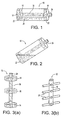
FIG. 1 is a front view of a preferred fuel cartridge oriented in an arbitrary position in accordance with the present invention; -
FIG. 2 is a front view of the fuel cartridge ofFIG. 1 orientated in another arbitrary position; -
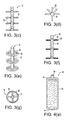
FIG. 3(a) is a front view of a preferred embodiment of the filler insert in accordance with the present invention;FIGS. 3(b)-3(d) are various views of another preferred embodiment of the filler insert; andFIGS. 3(e)-3(g) are various views of another preferred embodiment of the filler insert; -
FIG. 4(a) is a front view with a partial cutaway of another preferred embodiment of the filler insert in accordance with the present invention;FIGS. 4(b) and 4(c) are various views of another preferred embodiment of the filler insert; andFIGS. 4(d) and 4(e) are front views of other preferred embodiments of the filler insert; -
FIGS. 5(a), 5(b) and6 are alternative embodiments of the fuel cartridge shown inFIGS. 1 and 2 ; -
FIGS. 7(a)-7(b) are schematic views of alternative embodiments of an electro-osmotic pump controlling or regulating the flow of methanol fuel and/or water from the fuel cartridge(s) to the MEA; -
FIGS. 8(a)-8(b) are schematic views of the electro-osmotic pump with reversed polarity to stop the flow of fuel, and being electrically isolated from the fuel cartridge, respectively; -
FIG. 9 is another preferred embodiment of the fuel cartridge of the present invention with details omitted for clarity having a plurality of fuel chambers; -
FIG. 10 is another preferred embodiment of the fuel cartridge of the present invention with details omitted for clarity having a plurality of fuel chambers schematically connected to an optional diffuser/mixing element and to the MEA; and -
FIG. 11 is an alternative embodiment of the filler insert shown inFIGS. 1 and 2 with protective sheathing. - As illustrated in the accompanying drawings and discussed in detail below, the present invention is directed to a versatile fuel cartridge for storing fuel cell fuels such as methanol and water, methanol/water mixture, methanol/water mixtures of varying concentrations or pure methanol. The fuel cartridge may contain other types of fuel cell fuels, such as ethanol, or other chemicals that may improve the performance or efficiency of fuel cells, and the present invention is not limited to any type of fuels or liquids contained in the cartridge. The term "fuel" as used herein includes all fuels that can be reacted in fuel cells, and includes all of the above suitable fuels, liquids, and/or chemicals and mixtures thereof. The present invention utilizes a filler insert, which preferably occupies a small portion of the volume of the fuel cartridge, so that the fuel cartridge may hold more fuel to ensure a long life of the fuel cartridge, and to minimize the retention of fuel in the cartridge at the end of the useful life of the cartridge. The filler insert is capable of wicking and transporting the fuel to the MEA. Additionally, the filler insert remains substantially in physical contact with the fuel in any orientation of the fuel cartridge and at any fuel level in the fuel cartridge.
- Optionally, the fuel cartridge may also include a pump to initiate, maintain and/or control fuel flow from the fuel reservoir. The pump may also regulate the flow of fuel to the MEA to increase or decrease the electrical current output from the MEA, and importantly to shut off the flow of fuel, when necessary. Alternatively, a shut-off valve may be used to ensure that the flow of fuel is shut off when the electronic device is shut-off or when the cartridge is separated from the device. The pump or pumps may also mix pure methanol with water before pumping the mixture to the MEA. The pump may also selectively pump methanol/water mixture from different reservoirs having varying methanol concentrations.
- Preferably, the pump is adapted for use with low liquid flow rate, and preferably is available in small sizes for use with consumer electronic devices. Preferably, the pump has a minimal number of moving parts or more preferably no moving part to minimize breakage. Preferably, suitable pumps include microelectromechanical systems (MEMS) pumps, such as those used to pump ink in inkjet printers or those used in drug delivery systems or those used to cool micro integrated circuit chips, among others. More specifically, suitable MEMS pumps include field-induced flow pumps and membrane-displacement pumps. Field induced pumps utilize an electrical or magnetic field to produce flow. A suitable field-induced pump is an electro-osmotic pump, which is capable of moving liquid in small spaces, such as capillary spaces, by applying a direct circuit (DC) potential across at least a portion of a capillary column. The direction of fluid flow in the capillary column can also be reversed or stopped by reversing the direction of the DC potential. Other suitable field-induced pumps include, but are not limited to, electrohydrodynamic pumps and magnetohydrodynamic pumps. Membrane-displacement pumps utilize a force, e.g., an electrical charge, applied to a membrane, causing the membrane to move or vibrate to propel the fluid-to-be-pumped. Suitable membrane-displacement pumps include, but are not limited to electrostatic pumps and thermopneumatic pumps.
- As shown in
FIG. 1 ,fuel cartridge 10 comprises a free space portion and a portion occupied byfiller insert 12. Free space portion indicates that the space may be occupied by fuel or gas when the fuel level is less than full, but otherwise not occupied by other substances or materials.Insert 12 is preferably made from an absorbent material. Suitable absorbent materials include, but are not limited to, sponges and fibrous polymers such as polyester, polyethylene, polyolefin, polyacetal, polypropylene fibers, or from natural fibers such as hemp, cotton, or cellulose acetate or other plant-based fibers. Preferably, if polymeric fibers are used, these fibers are either thermoset or thermoplastic with high softening or melting temperature to withstand potentially high internal temperatures that may exist inside the fuel cells or inside the electronic devices. Filler materials of any porosity or permeability can be used, so long as the filler materials can wick fuel at a sufficient flow rate.Insert 12 preferably comprises two bases ordisks 14 and a connectingcolumn 16.Insert 12 preferably occupies less than about 67 % of the internal volume ofcartridge 10, more preferably less than about 50% and even more preferably less than about 33%, so that the free space portion and the interstitial volume withininsert 12 may be used to holdfuel 20. Alternatively, insert 12 may occupy all of the internal volume ofcartridge 10, preferably whencartridge 10 is utilized with a MEMS pump. - In
FIG. 1 ,cartridge 10 is shown arbitrarily in the horizontal position to replicate an electronic device, such as a calculator or PDA, being used. In this position,liquid fuel 20, which is shown as partially empty, may make contact withfiller insert 12, so thatfuel 20 may be communicated to insert 12 at contact points 22 for wicking to the MEA. Fuel is then transferred out ofcartridge 10 viaoutlet port 24.Outlet port 24 may contain the same filler material asinsert 12, so thatfuel 20 may be continually wicked out ofcartridge 10. Alternatively,outlet port 24 may comprise a single capillary needle or a bundle of capillary tubes. More preferably,outlet port 24 comprises a material more suitable with the selected pump to optimize flow from the cartridge and to control same. For example, if an electroosmotic pump is used,outlet port 24 preferably comprises glass or fused-silica capillary tubes or beads. - As illustrated in
FIG. 2 ,cartridge 10 can also be arbitrarily positioned at any tilt angle andfuel 20 would substantially maintain its contact withfiller insert 12 at contact point(s) 22. Similarly, whencartridge 10 is positioned vertically, such thatoutlet port 24 is positioned either at the top or bottom, the fuel remaining incartridge 10 substantially maintains contact withdisk 14 offiller insert 12. - Alternatively, as shown in
FIG. 3(a) ,filler insert 12 may comprise additional disk(s) 26 located betweendisks 14.Disk 26 may have any orientation, including but are not limited to, being parallel todisks 14.Disk 26 may be positioned diagonally betweendisks 14. For additional structural support, connectingcolumn 16 may be covered by athin plastic film 25, as shown inFIG. 11 . Advantageously, such thin film improves the flow of liquid throughinsert 12 by preventing air or other gases from entering the filler material. Alternatively,thin plastic film 25 may also at least partially coverdisk film covering column 14 intersects thefilm covering disk -
FIG. 3(b) illustrates another variation offiller insert 12, which comprisescolumn 16 and a plurality ofspokes 28.FIG. 3(c) is a cross-sectional view ofFIG. 3(b) showing a preferred fuel flow path within the insert.Spokes 28 may be aligned in straight lines as shown inFIGS. 3(b) and3(c) or may be unaligned as shown inFIG. 3(d). FIG. 3(e) illustrates another variation offiller insert 12, which comprisescolumn 16,spokes 28 and rings 29.FIG. 3(f) is a cross-sectional view ofFIG. 3(e) showing a preferred fuel flow path within the insert,FIG. 3(g) is a top view ofFIG. 3(e) .Spokes 28 can also be aligned or unaligned in this embodiment. - In another preferred embodiment,
filler insert 12 may compriseoutlet port 24,disks 14 and ashell 31.FIG. 4(a) , shown with a portion ofshell 31 removed for clarity, illustrates this embodiment. Sinceshell 31 anddisks 14 would cover the entire inside surface ofcartridge 10,fuel 20 would always remain in contact withinsert 12 at any fuel level and at any orientation of the cartridge. It is important to note that it is not necessary forshell 31 anddisks 14 to completely cover the inside surface ofcartridge 10 forfuel 20 to substantially maintain contact withinsert 12. For example, as shown inFIGS. 4(d) and 4(e) ,shell 31 may have a spiral shape or may comprise a plurality of spaced-apart strips, respectively, and partially covers the inner surface of the cartridge. As shown inFIGS. 4(d) and 4(e) , insert 12 may also haveoutlet port 24 and onedisk 14. Alternatively, this embodiment may also havesecond disk 14 and connectingcolumn 16. Furthermore, as shown inFIG. 4(b) ,filler insert 12 comprisesoutlet port 24,column 16,disk 14 andshell 31 connected serially in the manner shown.FIG. 4(c) is a cross-sectional view ofFIG. 4(b) showing the preferred fuel flow path within the insert. - Advantageously,
filler insert 12 may be used with other cartridges such ascartridge 30, which have outer surfaces with varying curvature, e.g., the hourglass-shaped cartridge shown inFIG. 5(a) or the bottle-shaped cartridge shown inFIG. 5(b) . As illustrated, the filler insert shown inFIGS.1-2 is used withcartridge 30 inFIG. 5(a) and the filler insert shown inFIGS. 4(b)-4(c) is shown withcartridge 30 inFIG. 5(b) .Disks 14 and/or rings 29 can also be modified to other shapes, such ashexagonal disks 34, to be utilized incartridge 32 shown inFIG. 6 . Hence, as used herein, the term "disk" or "ring" is not limited to any particular shape and includes circular and non-circular shapes as well as regular and irregular shapes. - As fuel is withdrawn from
cartridge filler insert 12 to draw fuel out of the cartridge. To overcome this effect, when the electronic consumer device is not in used, air or CO2 produced by the fuel cell reaction may be allowed to flow into the cartridge throughoutlet port 24 to eliminate the partial vacuum. In applications whereoutlet port 24 is connected in an airtight manner to the MEA or where the fuel cell is used continuously for a long period of time, avent 36 may be provided to allow air to enter the cartridge to equalize the internal pressure of the cartridge to the external pressure.Vent 36, shown schematically inFIG. 6 , can be a one-way valve that only allows air to enter but does not allow fuel or other liquids to exit. Alternatively, vent 36 is an opening covered by a hydrophobic membrane, such that methanol, water or other liquids cannot pass through but air is allowed to enter the cartridge. Hydrophobic membranes can be made from polytetrafluoroethylene (PTFE), nylon, polyamides, polyvinylidene, polypropylene, polyethylene or other polymeric membrane. A commercially available hydrophobic PTFE microporous membrane can be obtained from W.L Gore Associates, Inc. Additionally, arefill valve 38 may be provided to add fuel tocartridge air vent 36 andvalve 38 are illustrated in connection withFIG. 6 , these devices are applicable to all cartridge embodiments shown and claimed herein. - To ensure that the fuel flow from
outlet port 24 of the fuel cartridge to the MEA is regulated, an optional pump is provided. Any pump can be used so long as fuel can be pumped from the cartridge in a regulated manner. Preferably, the pump is a MEMS pump to minimize the size of the pump. Electro-osmotic pump is one of the MEMS pumps usable with the present invention. As shown inFIGS. 7(a)-7(c) , an electro-osmotic pump 39 is provided. Electro-osmotic pump 39 contains no moving parts and is capable of moving fluids through tight spaces. Electro-osmotic pump advantageously can move fluid with low conductivity. An electro-osmotic flow is created when a DC potential is applied across a porous media. The liquid in the porous media is driven from the anode or positive electrode to the cathode or negative electrode, when exposed to the DC electrical field. Electro-osmotic pump is particularly useful in micro-channels, such as those withinfiller insert 12 oroutlet port 24, and in slow and controlled flow, which is very useful in DMFC. Electro-osmotic flow is discussed in details inU.S. patent no. 3,923,426 entitled, "Electroosmotic Pump and Fluid Dispenser Including Same," issued on December 2, 1975, in "Electroosmotic flow pumps with polymer frits" by S. Zeng, C. Chen, J. Santiago, J. Chen, R. Zare, J. Tripp, F. Svec and J. Frechet, published in Sensors and Actuators B Chemical Journal , vol. 82, pp. 209-212 (2002), and in "A Large Flowrate Electroosmotic Pump with Micron Pores," by S. Yao, D. Huber, J. Mikkelsen and J. Santiago, proceedings of IMECE, 2001 ASME International Mechanical Engineering Congress and Exposition, November 11-16, 2001, New York, NY, among other references. These references are incorporated by reference herein in their entireties. - As shown in
FIG. 7(a) , a DC potential can be applied acrossentire insert 12 to ensure that the fuel flow out ofcartridge 10 is regulated. More preferably, a DC potential is applied acrossonly outlet port 24, since less voltage is required and once the fuel begins to flow throughoutlet port 24 momentum is transferred to the remaining fuel through viscous interaction.Battery 40 is selected to have any potential necessary to induce fuel flow. One ormore battery 40 can be stacked in series to increase the applied DC potential, as shown inFIG. 7(c) . Alternatively, a DC-DC converter can be used to increase the DC potential output. The DC-DC converter converts low voltage DC to alternating current (AC) voltage (or to electrical pulses), and then transforms the low AC voltage to higher AC voltage before reconverting it to DC voltage. Advantageously, DC-DC converters are available in small sizes. When the fuel stored in the free space of the fuel cartridge is used up, electro-osmotic pump 39 can pump fuel out ofinsert 12 to render most of this fuel usable. To minimize the draw frombattery 40, the electrical potential from the fuel cell can be used to power the electro-osmotic flow once the fuel cell is operational. Preferably,controller 42 is provided to control the potential and/or to invert the polarity ofbattery 40. - In accordance with one aspect of the present invention,
battery 40 is rechargeable so that the current from the fuel cell, when it is in operation, may rechargebattery 40. Advantageously,battery 40 can be continually recharged to prolong battery life, and the consumer may not realize that a battery is used within the fuel cell. In accordance with another aspect of the present invention, amanual pump 44, such as a hand-operated air pump, can be provided to manually pump the fuel to activate the MEA when thebattery 40 is run down, or after a long period of inactivity the fuel is drained fromoutlet port 24 or from most ofinsert 12, or when the capillary spacing is blocked. - Another advantage of electro-
osmotic pump 39 is that when the MEA needs to be shut down, controller/inverter 42 can reverse the polarity ofbattery 40 so that fuel is forced to flow away from the MEA to stop the fuel cell reaction to disengage the electrical circuit, as shown inFIG. 8(a) . Alternatively, a shut-offvalve 45, as shown inFIG. 6 , may be provided to isolate the fuel from the MEA. Shut-offvalve 45 can also help prevent the unintended discharge of fuel from the fuel cartridge, when the cartridge is separated from the electronic device. Shut-off valve can be positioned either above or belowrefill valve 38. Shut-offvalve 45 can be a normally opened valve or a normally closed valve, as discussed in commonly-owned United States patent5,520,197 . The '197 patent is hereby incorporated by reference in its entirety. - After the fuel cell's electrical production is stopped, a manual or
electronic switch 44 is opened to remove any DC potential acrossfiller insert 12 oroutlet port 24.Controller 42, for example, can be operatively connected to the on/off switch of the consumer electronic device, such that when the device is turned on, a DC potential is applied acrossinsert 12 oroutlet port 24. When the device is turned off, the DC potential is reversed and then disconnected.Controller 42 may also control the rate of fuel flow from the fuel cartridge by varying the DC potential applied. One method of varying the DC potential is described below. -
Battery 40 and controller/inverter 42 may be located on the fuel cartridge, preferably when the cartridge is refillable, or may be located in the fuel cell so that the costs for producing the fuel cartridges may be reduced to make the fuel cartridge disposable after a single-use. - In accordance with another aspect of the invention,
fuel cartridge 10 may comprise two or more chambers. As shown inFIG. 9 ,fuel cartridge 10 may havechambers FIG. 9 , the connectingcolumn 50 ofchamber 48 is disposed concentrically inside connectingcolumn 52 ofchamber 46. Preferably,column 50 is isolated fromcolumn 52 by a waterproof film. As shown, each column is connected to disks to ensure that the liquid contained therein is wicked out of the chambers. Alternatively, the chambers can be positioned side-by-side, such aschambers FIG. 10 . Eachchamber column FIGS. 9 and 10 , the methanol and water streams need to be combined or mixed before reaching the MEA. Preferably, the liquids are mixed in diffuser or mixingzone 62. Preferablyzone 62 is filled with the same filler material asinsert 12 to spread the fuel mixture by capillary action before reaching the MEA. Additionally, a premixing chamber may be provided upstream of diffuser or mixingzone 62, so that the liquids may be thoroughly mixed before reaching thediffuser 62. - Different fuel cells may require different concentrations of methanol to water in the fuel mixture for operation. This can be accomplished by the electro-osmotic pump shown schematically in
FIG. 7(c) . The same DC potential can be applied tochambers inverter 42 may have multiple outputs, and each output may have a different voltage to regulate the flows out of the chambers. Alternatively, in one preferred embodiment, each output may have avariable resistor 64 to adjust the voltage of the output as illustrated inFIG. 7(b) . Alternatively, the variable resistor can be located in series with the chamber to adjust the voltage applied to the chamber, as illustrated inFIG. 7(c) . - Alternatively,
chambers osmotic pump 39 can selectively pump the fuel mixture out of one or the other chamber depending on the power consumption requirements. This can be accomplished by increasing the resistance inresistor 64 connected with the unneeded chamber, so that it is significantly higher than the impedance or resistance of the filler insert in the chamber. When the resistance ofresistor 64 is sufficiently high, the DC potential across the filler insert is insignificantly small thereby effectively stopping the flow from the unneeded chamber and only allowing the flow to come from the selected chamber. The fuel mixtures in the two or more chambers may be mixed together before reaching the MEA, as explained above. Alternatively, each chamber may have its own pump to regulate or control the flow of fuel therefrom. - In accordance with other embodiments of the invention, other pumps can be utilized with
fuel cartridges - An electrohydrodynamic pump applies an AC voltage field to a fluid-to-be-pumped. An example of an electrohydrodynamic pump is disclosed in United States patent no.
4,316,233 , entitled "Single Phase Electrohydrodynamic Pump," issued on February 16, 1982. The '233 patent is hereby incorporated by reference in its entirety. An electrohydrodynamic pump generally works by the attractive and repulsive forces exerted on the fluid by an electric field through Coulombic reaction. Since the electrical field acts on the fluid and not through mechanical pressure, the internal pressure within the fluid does not increase significantly due to the pumping. An electrohydrodynamic pump is particularly suitable for liquid with low electrical conductivity. As disclosed in and shown in the figures of the '233 patent, an AC charge is applied to a flow conduit, wherein the flow conduit comprises a plurality of internal projections of semi-insulating material hanging from the conduit wall. This flow conduit advantageously can beoutlet port 24 offiller insert 12. The projections are made from different materials having different electrical relaxation times, such that the electrical charge for each projection reaches its peak at different times. This creates an AC electrical field in the fluid. For example, if the AC charge is a sinusoidal voltage, the voltages at the tips of the projections cause a sinusoidal electrical field to pump the fluid in a desired direction. Alternatively, the projections can be made from the same materials but have different dimensions to have different relaxation times. The projections may be spaced apart or positioned adjacent to each other. The projections may also have any geometrical shapes. - It is known that electrohydrodynamic flow can be used in combination with electro-osmotic flow to pump fluid, and it has also been reported that electrohydrodynamic and electro-osmotic pumps can be used together to pump methanol and ethanol through capillary tubes.
- A magnetohydrodynamic pump, on the other hand, applies a magnetic field to a working fluid to move the working fluid in any desired direction. The flow of working fluid can be reversed by reversing the magnetic field. An example of a magnetohydrodynamic pump is disclosed in United States patent no.
6,241,480 , entitled "Micro-magnetohydrodynamic Pump and Method for Operation of the Same," issued on June 5, 2001. The '480 patent is incorporated herein by reference in its entirety. Any conductive liquid can be the working fluid. Preferably, the working fluid is a highly viscous, liquid metal, such as mercury or gallium alloys. In a preferred embodiment, the magnetohydrodynamic pump comprises a chamber having an inlet and an outlet with a mass of the liquid metal acting as a piston. A magnetic field generated by permanent magnet, electromagnet or an array of spiral magnetic inductors is applied to the working fluid to move the working fluid away from the inlet to draw the fluid-to-be-pumped into the chamber. The magnetic field is then reversed to pump the fluid out of the chamber through the outlet. The magnetohydrodynamic pump may have an additional chamber for holding the liquid to be pumped. Each of the inlet and outlet preferably has a check valve to control the flow of the fluid-to-be-pumped. The inlet is preferably in fluid communication withoutlet port 24 and the outlet is preferably in fluid communication with the MEA to transport the fluid to the MEA. - An electrostatic pump is a membrane-displacement pump, which is different than the field-induced pumps discussed above. Instead of applying an electrical or magnetic field (or both) to a fluid and pumping the fluid, a membrane-displacement pump typically includes a membrane or diaphragm and a force applied to the membrane or diaphragm to pump the fluid. In an electrostatic pump, an electrical potential is applied to a membrane or diaphragm causing the membrane or diaphragm to move or to vibrate to pump the fluid. An electrostatic pump is disclosed in United States patent no.
6,485,273 , entitled "Disiributed MEMS Electrostatic Pumping Devices," issued on November 26, 2002. The '273 patent discloses, among other things, a MEMS pump, which has a movable membrane attached in a cantilevered manner to a substrate. The membrane is biased at the free end away from the substrate. When an electrostatic voltage is applied across a first electrode in the movable membrane and a second electrode in the substrate, the movable membrane moves toward the substrate. Such movement pumps any fluid-to-be-pumped located between the free end of the movable membrane and the substrate. When the electrostatic force is removed, the movable membrane is biased back to its original position. This cycle may be repeated to continually pump the fluid. Another electrostatic pump is disclosed in United States patent no.5,336,062 , entitled "Microminiaturized Pump," issued on August 9, 1994. The '062 patent discloses, among other things, an electrostatic pump having at least one membrane. When an AC voltage is applied to the membrane through its "ohmic" contact, the membrane vibrates to pump fluid. The '062 patent also discloses a two membrane embodiment, where two AC voltages having different phases and voltages are applied to the membranes, such that the membranes may vibrate in opposite phase to one another to pump fluid. The disclosure of the '273 patent and the '062 patent are incorporated herein by reference in their entireties. - A thermopneumatic pump is another membrane-displacement pump. In this pump a heating element, e.g., a resistive heating element, is disposed in a pressure chamber and the pressure chamber is operatively connected to the membrane. Enclosed in the chamber is a quantity of either working gas or working liquid that expands when heated. Suitable working liquids include fluorinated hydrocarbon liquids available from 3M. Such thermal expansion generates a force against the membrane and moves the membrane. The movement of the membrane pumps the fluid-to-be-pumped. A reduction in temperature of the enclosed working gas or liquid contracts the membrane. Thermopneumatic pump and other membrane displacement micropumps are disclosed in United States patent no.
6,069,392 , entitled "Microbellows Actuator," issued on May 30, 2000 andU.S. patent no. 6,326,211 , entitled "Method of Manipulating a Gas Bubble in a Microfluidic Device" issued on December 4, 2001. These references are incorporated by reference in their entireties. - The
fuel cartridges - While it is apparent that the illustrative embodiments of the invention disclosed herein fulfill the objectives of the present invention, it is appreciated that numerous modifications and other embodiments may be devised by those skilled in the art. Additionally, feature(s) and/or element(s) from any embodiment may be used singly or in combination with other embodiment(s). Therefore, it will be understood that the appended claims are intended to cover all such modifications and embodiments, which would come within the spirit and scope of the present invention.
Claims (16)
- A fuel cartridge containing fuel suitable for use with a fuel cell comprising a filler insert and the fuel cartridge is operatively connectable to a microelectromechanical pump to control the flow of fuel out of the cartridge, wherein the filler insert comprises an absorbent material capable of wicking fuel contained within the cartridge by capillary action, and wherein the filler insert is substantially in contact with the fuel at any orientation of the cartridge and at any fuel level.
- The fuel cartridge of claim 1, wherein the absorbent material is made from polymeric fibers.
- The fuel cartridge of claim 1, wherein the absorbent material is made from plant-based fibers.
- The fuel cartridge of claim 1, wherein the cartridge further comprising an air vent.
- The fuel cartridge of claim 1, wherein the cartridge further comprising a refillable valve.
- The fuel cartridge of claim 1, wherein the microelectromechanical pump comprises a field-induced pump.
- The fuel cartridge of claim 6, wherein the microelectromechanical pump comprises an electrical field applied to the fuel to pump the fuel.
- The fuel cartridge of claim 6, wherein the microelectromechanical pump comprises a magnetic field applied to a working fluid to pump the fuel.
- The fuel cartridge of claim 1, wherein the microelectromechanical pump comprises an electrohydrodynamic pump.
- The fuel cartridge of claim 1, wherein the microelectromechanical pump comprises an electrohydrodynamic pump and an electro-osmotic pump.
- The fuel cartridge of claim 1, wherein the microelectromechanical pump comprises a magnetohydrodynamic pump.
- The fuel cartridge of claim 1, wherein the pump comprises an electro-osmotic pump.
- The fuel cartridge of claim 1, wherein the microelectromechanical pump comprises a membrane-displacement pump.
- The fuel cartridge of claim 13, wherein the membrane-displacement pump comprises a membrane and a force is applied to the membrane causing the membrane to move to pump the fuel.
- The fuel cartridge of claim 1, wherein the pump comprises an electrostatic pump.
- The fuel cartridge of claim 1, wherein the pump comprises a thermopneumatic pump.
Applications Claiming Priority (3)
| Application Number | Priority Date | Filing Date | Title |
|---|---|---|---|
| US10/356,793 US7147955B2 (en) | 2003-01-31 | 2003-01-31 | Fuel cartridge for fuel cells |
| EP04705143A EP1588440B1 (en) | 2003-01-31 | 2004-01-26 | Fuel cartridge for fuel cells |
| EP07104005A EP1791209B1 (en) | 2003-01-31 | 2004-01-26 | Fuel Cartridge for Fuel Cells |
Related Parent Applications (2)
| Application Number | Title | Priority Date | Filing Date |
|---|---|---|---|
| EP04705143.8 Division | 2004-01-26 | ||
| EP07104005.9 Division | 2007-03-13 |
Publications (2)
| Publication Number | Publication Date |
|---|---|
| EP2259372A2 true EP2259372A2 (en) | 2010-12-08 |
| EP2259372A3 EP2259372A3 (en) | 2011-03-09 |
Family
ID=32770877
Family Applications (3)
| Application Number | Title | Priority Date | Filing Date |
|---|---|---|---|
| EP07104005A Expired - Lifetime EP1791209B1 (en) | 2003-01-31 | 2004-01-26 | Fuel Cartridge for Fuel Cells |
| EP04705143A Expired - Lifetime EP1588440B1 (en) | 2003-01-31 | 2004-01-26 | Fuel cartridge for fuel cells |
| EP10180871A Withdrawn EP2259372A3 (en) | 2003-01-31 | 2004-01-26 | Fuel cartridge for fuel cells |
Family Applications Before (2)
| Application Number | Title | Priority Date | Filing Date |
|---|---|---|---|
| EP07104005A Expired - Lifetime EP1791209B1 (en) | 2003-01-31 | 2004-01-26 | Fuel Cartridge for Fuel Cells |
| EP04705143A Expired - Lifetime EP1588440B1 (en) | 2003-01-31 | 2004-01-26 | Fuel cartridge for fuel cells |
Country Status (19)
| Country | Link |
|---|---|
| US (2) | US7147955B2 (en) |
| EP (3) | EP1791209B1 (en) |
| JP (1) | JP4742024B2 (en) |
| KR (1) | KR100834349B1 (en) |
| CN (1) | CN1816933B (en) |
| AR (1) | AR042908A1 (en) |
| AT (2) | ATE362659T1 (en) |
| AU (1) | AU2004208231B2 (en) |
| BR (1) | BRPI0406200A (en) |
| CA (1) | CA2513650C (en) |
| DE (1) | DE602004006488T2 (en) |
| ES (2) | ES2376575T3 (en) |
| MX (1) | MXPA05008059A (en) |
| MY (1) | MY141522A (en) |
| PL (1) | PL379586A1 (en) |
| RU (1) | RU2316852C2 (en) |
| TW (1) | TWI237416B (en) |
| WO (1) | WO2004068611A2 (en) |
| ZA (1) | ZA200505791B (en) |
Cited By (1)
| Publication number | Priority date | Publication date | Assignee | Title |
|---|---|---|---|---|
| US9005321B2 (en) | 2012-03-19 | 2015-04-14 | Intelligent Energy Inc. | Hydrogen generator system with liquid interface |
Families Citing this family (66)
| Publication number | Priority date | Publication date | Assignee | Title |
|---|---|---|---|---|
| JP2003072059A (en) * | 2001-06-21 | 2003-03-12 | Ricoh Co Ltd | Inkjet recorder and duplicator |
| US20050008924A1 (en) * | 2003-06-20 | 2005-01-13 | Sanjiv Malhotra | Compact multi-functional modules for a direct methanol fuel cell system |
| US7452625B2 (en) * | 2003-06-20 | 2008-11-18 | Oorja Protonics | Water management in a direct methanol fuel cell system |
| WO2005004258A2 (en) * | 2003-06-27 | 2005-01-13 | Ultracell Corporation | Portable fuel cartridge for fuel cells |
| US8613297B2 (en) | 2003-07-29 | 2013-12-24 | Societe Bic | Fuel supply systems having operational resistance |
| US7172825B2 (en) * | 2003-07-29 | 2007-02-06 | Societe Bic | Fuel cartridge with flexible liner containing insert |
| US7481858B2 (en) * | 2005-02-25 | 2009-01-27 | Societe Bic | Hydrogen generating fuel cell cartridges |
| JP4529451B2 (en) * | 2003-10-23 | 2010-08-25 | 株式会社日立製作所 | FUEL CELL DEVICE, ITS CONTROL METHOD, AND ELECTRONIC DEVICE |
| US7655331B2 (en) | 2003-12-01 | 2010-02-02 | Societe Bic | Fuel cell supply including information storage device and control system |
| US20050162122A1 (en) * | 2004-01-22 | 2005-07-28 | Dunn Glenn M. | Fuel cell power and management system, and technique for controlling and/or operating same |
| US8486575B2 (en) * | 2004-02-05 | 2013-07-16 | GM Global Technology Operations LLC | Passive hydrogen vent for a fuel cell |
| US7117906B2 (en) | 2004-02-06 | 2006-10-10 | Societe Bic | Datum based interchangeable fuel cell cartridges |
| US20050233190A1 (en) * | 2004-04-15 | 2005-10-20 | Gennadi Finkelshtain | Fuel cell with removable/replaceable cartridge and method of making and using the fuel cell and cartridge |
| US7521140B2 (en) * | 2004-04-19 | 2009-04-21 | Eksigent Technologies, Llc | Fuel cell system with electrokinetic pump |
| US20050260465A1 (en) * | 2004-05-18 | 2005-11-24 | Harris Scott C | Direct methanol fuel cell system, fuel cartridge, system of operation, and system for detecting forgery |
| US7968250B2 (en) | 2004-06-25 | 2011-06-28 | Ultracell Corporation | Fuel cartridge connectivity |
| US7648792B2 (en) | 2004-06-25 | 2010-01-19 | Ultracell Corporation | Disposable component on a fuel cartridge and for use with a portable fuel cell system |
| US20060006108A1 (en) * | 2004-07-08 | 2006-01-12 | Arias Jeffrey L | Fuel cell cartridge and fuel delivery system |
| US7799453B2 (en) | 2004-08-04 | 2010-09-21 | The Board Of Trustees Of The Leland Stanford Junior University | Fuel cell with electroosmotic pump |
| JP2006085952A (en) * | 2004-09-15 | 2006-03-30 | Hitachi Maxell Ltd | Fuel cell, power supply system, and electronic apparatus |
| US20060071088A1 (en) * | 2004-10-05 | 2006-04-06 | Paul Adams | Fuel cartridge with an environmentally sensitive valve |
| JP4753569B2 (en) * | 2004-11-24 | 2011-08-24 | 三菱鉛筆株式会社 | Fuel cartridge and fuel cell |
| CN104554830B (en) * | 2005-02-16 | 2017-09-19 | 智能能源有限公司 | Fuel make up system and device with operation resistance |
| US7727293B2 (en) | 2005-02-25 | 2010-06-01 | SOCIéTé BIC | Hydrogen generating fuel cell cartridges |
| TWI296599B (en) * | 2005-06-13 | 2008-05-11 | Wisepoint Technology Co Ltd | Beam jet propellor |
| US7829211B2 (en) * | 2005-06-15 | 2010-11-09 | Univeristy Of Connecticut | Thermal-fluids management system for direct methanol fuel cells |
| DE102005039887A1 (en) * | 2005-08-23 | 2007-03-08 | Siemens Ag | Solid state detector for recording digital X-ray images |
| US20070084523A1 (en) * | 2005-09-23 | 2007-04-19 | Angstrom Power Incorporated | Systems and methods for replenishing fuel-cell-powered portable devices |
| JP2007095400A (en) * | 2005-09-28 | 2007-04-12 | Hitachi Ltd | Fuel cartridge |
| US7779856B2 (en) * | 2005-10-05 | 2010-08-24 | Societe Bic | Fuel cartridge of a fuel cell with fuel stored outside fuel liner |
| KR100695112B1 (en) * | 2005-11-02 | 2007-03-14 | 삼성에스디아이 주식회사 | Direct liquid feed fuel cell system having double fuel storage |
| DK1957794T3 (en) | 2005-11-23 | 2014-08-11 | Eksigent Technologies Llc | Electrokinetic pump designs and drug delivery systems |
| US8196894B2 (en) * | 2006-01-06 | 2012-06-12 | Societe Bic | Check valves for fuel cartridges |
| US20080029156A1 (en) * | 2006-01-19 | 2008-02-07 | Rosal Manuel A D | Fuel cartridge |
| US20070231621A1 (en) * | 2006-01-19 | 2007-10-04 | Rosal Manuel A D | Fuel cartridge coupling valve |
| JP5105758B2 (en) | 2006-03-27 | 2012-12-26 | 三洋電機株式会社 | Fuel cell system |
| JP4285518B2 (en) * | 2006-03-28 | 2009-06-24 | カシオ計算機株式会社 | Connection structure, flow path control unit, fuel cell power generator and electronic device |
| JP4893195B2 (en) | 2006-09-27 | 2012-03-07 | カシオ計算機株式会社 | Liquid feeder connection structure, fuel cell type power generator and electronic device |
| JP2008091080A (en) * | 2006-09-29 | 2008-04-17 | Casio Comput Co Ltd | Liquid cartridge, power generating device, and electronic apparatus |
| US8076820B2 (en) * | 2006-10-06 | 2011-12-13 | Teledyne Licensing, Llc | High energy density electro-osmotic pump and actuator |
| WO2008066547A1 (en) * | 2006-11-28 | 2008-06-05 | Utc Power Corporation | Fuel cell power plant including a variable resistive device |
| US7867592B2 (en) | 2007-01-30 | 2011-01-11 | Eksigent Technologies, Inc. | Methods, compositions and devices, including electroosmotic pumps, comprising coated porous surfaces |
| KR100811984B1 (en) * | 2007-02-15 | 2008-03-10 | 삼성에스디아이 주식회사 | Fuel cartridge and fuel cell using the same |
| JP5025288B2 (en) * | 2007-03-05 | 2012-09-12 | 株式会社東芝 | Fuel cell system and electronic device |
| JP4930783B2 (en) * | 2007-05-28 | 2012-05-16 | ソニー株式会社 | Liquid tank and liquid tank tubular structure, fuel cell, and electronic device |
| TWI350609B (en) * | 2007-07-30 | 2011-10-11 | Young Green Energy Co | Fuel cell device |
| GB0720203D0 (en) * | 2007-10-16 | 2007-11-28 | Goryanin Irina | Microbial fuel cell cathode assembly |
| US8251672B2 (en) | 2007-12-11 | 2012-08-28 | Eksigent Technologies, Llc | Electrokinetic pump with fixed stroke volume |
| JP2009277560A (en) * | 2008-05-16 | 2009-11-26 | Sony Corp | Fuel cartridge and fuel cell system |
| EP2353199B1 (en) | 2008-11-03 | 2019-10-16 | Intelligent Energy Limited | Hydrogen-generating fuel cell cartridges |
| US8986404B2 (en) | 2009-11-03 | 2015-03-24 | Societe Bic | Gas generator with starter mechanism and catalyst shield |
| US8636826B2 (en) | 2009-11-03 | 2014-01-28 | Societe Bic | Hydrogen membrane separator |
| US20100124679A1 (en) * | 2008-11-20 | 2010-05-20 | Mti Microfuel Cells, Inc. | Method for increasing the durability of direct oxidation fuel cells |
| WO2010110862A2 (en) * | 2009-03-23 | 2010-09-30 | Vacca, Inc, | Safety fuel transportation, storage, and delivery system |
| JP2010236799A (en) * | 2009-03-31 | 2010-10-21 | Sony Corp | Liquid tank and fuel cell |
| CN101599549B (en) * | 2009-07-02 | 2011-01-12 | 哈尔滨工业大学水资源国家工程研究中心有限公司 | Self-respiration direct methanol fuel battery system based on metal polar plate and preparation method thereof |
| TWI398983B (en) * | 2010-04-28 | 2013-06-11 | Nat Univ Chin Yi Technology | Used in direct methanol fuel cell magnetic micro-pump and its direct methanol fuel cell |
| CA2834708A1 (en) | 2011-05-05 | 2012-11-08 | Eksigent Technologies, Llc | Gel coupling for electrokinetic delivery systems |
| JP5806923B2 (en) * | 2011-12-15 | 2015-11-10 | シャープ株式会社 | Fuel tank for fuel cell |
| US20140193735A1 (en) * | 2013-01-04 | 2014-07-10 | Lilliputian Systems, Inc. | Low Vibration Linear Motor Systems |
| CN104919636A (en) * | 2013-03-15 | 2015-09-16 | 俄勒冈州立大学 | Microbial fuel cell and methods of use |
| USD741254S1 (en) | 2013-10-11 | 2015-10-20 | Intelligent Energy Limited | Modular hydrogen fuel cartridge |
| CN107250779B (en) * | 2015-01-30 | 2021-05-28 | 惠普发展公司,有限责任合伙企业 | Diagnostic chip |
| WO2016122577A1 (en) * | 2015-01-30 | 2016-08-04 | Hewlett-Packard Development Company, L.P. | Diagnostic chip |
| RU185789U1 (en) * | 2018-01-26 | 2018-12-19 | Сайфудинов Сергей Константинович | HYDROGEN BATTERY BASED ON CAPILLARY AND MULTICAPILLARY STRUCTURES FOR POWER INSTALLATION OF UNMANNED AERIAL VEHICLES |
| CN111370619B (en) * | 2020-04-17 | 2021-01-19 | 福建南平延平区南孚新能源科技有限公司 | Rechargeable button cell |
Citations (18)
| Publication number | Priority date | Publication date | Assignee | Title |
|---|---|---|---|---|
| US3923426A (en) | 1974-08-15 | 1975-12-02 | Alza Corp | Electroosmotic pump and fluid dispenser including same |
| US4316233A (en) | 1980-01-29 | 1982-02-16 | Chato John C | Single phase electrohydrodynamic pump |
| US5336062A (en) | 1990-02-27 | 1994-08-09 | Fraunhofer-Gesellschaft Zur Forderung Der Angewandten Forschung E.V. | Microminiaturized pump |
| US5520197A (en) | 1993-07-28 | 1996-05-28 | Bic Corporation | Lighter with guard |
| US5709961A (en) | 1996-06-06 | 1998-01-20 | Lynntech, Inc. | Low pressure fuel cell system |
| US5945231A (en) | 1996-03-26 | 1999-08-31 | California Institute Of Technology | Direct liquid-feed fuel cell with membrane electrolyte and manufacturing thereof |
| US5992008A (en) | 1998-02-10 | 1999-11-30 | California Institute Of Technology | Direct methanol feed fuel cell with reduced catalyst loading |
| US6069392A (en) | 1997-04-11 | 2000-05-30 | California Institute Of Technology | Microbellows actuator |
| US6241480B1 (en) | 1998-12-29 | 2001-06-05 | The Regents Of The Unversity Of California | Micro-magnetohydrodynamic pump and method for operation of the same |
| US6268077B1 (en) | 1999-03-01 | 2001-07-31 | Motorola, Inc. | Portable fuel cell power supply |
| US6326097B1 (en) | 1998-12-10 | 2001-12-04 | Manhattan Scientifics, Inc. | Micro-fuel cell power devices |
| US6326211B1 (en) | 1995-06-29 | 2001-12-04 | Affymetrix, Inc. | Method of manipulating a gas bubble in a microfluidic device |
| US20010051293A1 (en) | 2000-06-13 | 2001-12-13 | Narayanan Sekharipuram R. | Reduced size fuel cell for portable applications |
| US20020018925A1 (en) | 2000-07-24 | 2002-02-14 | Alcatel | System for storing fuel in a handheld device |
| US6447941B1 (en) | 1998-09-30 | 2002-09-10 | Kabushiki Kaisha Toshiba | Fuel cell |
| US20020127451A1 (en) | 2001-02-27 | 2002-09-12 | Yiding Cao | Compact direct methanol fuel cell |
| US6460733B2 (en) | 2001-02-20 | 2002-10-08 | Mti Microfuel Cells, Inc. | Multiple-walled fuel container and delivery system |
| US6485273B1 (en) | 2000-09-01 | 2002-11-26 | Mcnc | Distributed MEMS electrostatic pumping devices |
Family Cites Families (95)
| Publication number | Priority date | Publication date | Assignee | Title |
|---|---|---|---|---|
| US8193A (en) * | 1851-07-01 | Bread-cutter | ||
| US127141A (en) * | 1872-05-28 | Improvement in compounds for destroying insects | ||
| US122966A (en) * | 1872-01-23 | Improvement in devices for moving pianos | ||
| US86193A (en) * | 1869-01-26 | Improvement in floats for life-preservers | ||
| US102451A (en) * | 1870-04-26 | Improved metaii-roof protector | ||
| US3253430A (en) * | 1964-03-10 | 1966-05-31 | Firefly Lighter Inc | Lighter assembly |
| US3774243A (en) | 1971-10-20 | 1973-11-27 | D Ng | Implantable power system for an artificial heart |
| US4419663A (en) * | 1979-03-14 | 1983-12-06 | Matsushita Electric Industrial Co., Ltd. | Display device |
| US4294891A (en) * | 1980-03-12 | 1981-10-13 | The Montefiore Hospital Association Of Western Pennsylvania | Intermittently refuelable implantable bio-oxidant fuel cell |
| JPS5738163A (en) * | 1980-08-18 | 1982-03-02 | Matsushita Electric Ind Co Ltd | Image recording method and apparatus therefor |
| US4396925A (en) * | 1980-09-18 | 1983-08-02 | Matsushita Electric Industrial Co., Ltd. | Electroosmotic ink printer |
| US4387382A (en) * | 1980-10-07 | 1983-06-07 | Matsushita Electric Industrial Co., Ltd. | Ink recording apparatus |
| JPS585268A (en) | 1981-07-02 | 1983-01-12 | Matsushita Electric Ind Co Ltd | Ink recording head |
| US4420544A (en) * | 1981-10-02 | 1983-12-13 | California Institute Of Technology | High performance methanol-oxygen fuel cell with hollow fiber electrode |
| US4481520A (en) * | 1982-02-03 | 1984-11-06 | Matsushita Electric Industrial Co., Ltd. | Electroosmotic ink printer head |
| US4525727A (en) * | 1982-02-17 | 1985-06-25 | Matsushita Electric Industrial Company, Limited | Electroosmotic ink printer |
| US4463068A (en) * | 1982-09-30 | 1984-07-31 | Engelhard Corporation | Fuel cell and system for supplying electrolyte thereto with wick feed |
| US4463066A (en) * | 1982-09-30 | 1984-07-31 | Engelhard Corporation | Fuel cell and system for supplying electrolyte thereto |
| JPS6062064A (en) * | 1983-09-14 | 1985-04-10 | Hitachi Ltd | Liquid fuel cell |
| JPS60189174A (en) * | 1984-03-07 | 1985-09-26 | Hitachi Ltd | Fuel cell |
| IE60941B1 (en) * | 1986-07-10 | 1994-09-07 | Elan Transdermal Ltd | Transdermal drug delivery device |
| GB8724543D0 (en) * | 1987-10-20 | 1987-11-25 | Johnson Matthey Plc | Demonstrating & studying operation of fuel cell |
| JP2619288B2 (en) * | 1989-06-15 | 1997-06-11 | 大日精化工業株式会社 | Manufacturing method of colored laminated glass |
| DE3925749C1 (en) * | 1989-08-03 | 1990-10-31 | Fraunhofer-Gesellschaft Zur Foerderung Der Angewandten Forschung Ev, 8000 Muenchen, De | |
| JPH05166522A (en) * | 1991-12-11 | 1993-07-02 | Hitachi Ltd | Fuel cell |
| US5364711A (en) | 1992-04-01 | 1994-11-15 | Kabushiki Kaisha Toshiba | Fuel cell |
| JPH0684533A (en) * | 1992-08-31 | 1994-03-25 | Sumitomo Electric Ind Ltd | Humidifying means for solid high polymer type fuel cell |
| JP3064167B2 (en) * | 1993-09-01 | 2000-07-12 | 三菱重工業株式会社 | Solid electrolyte fuel cell |
| US5659171A (en) * | 1993-09-22 | 1997-08-19 | Northrop Grumman Corporation | Micro-miniature diaphragm pump for the low pressure pumping of gases |
| US5773162A (en) * | 1993-10-12 | 1998-06-30 | California Institute Of Technology | Direct methanol feed fuel cell and system |
| US5599638A (en) * | 1993-10-12 | 1997-02-04 | California Institute Of Technology | Aqueous liquid feed organic fuel cell using solid polymer electrolyte membrane |
| SE9400821D0 (en) * | 1994-03-10 | 1994-03-10 | Siemens Elema Ab | Implantable infusion system with pressure neutral drug container |
| US5534363A (en) | 1994-03-22 | 1996-07-09 | Rockwell International Corporation | Hollow artery anode wick for passive variable pressure regenerative fuel cells |
| AU705351B2 (en) * | 1994-11-10 | 1999-05-20 | Orchid Biosciences, Inc. | Liquid distribution system |
| US5632876A (en) * | 1995-06-06 | 1997-05-27 | David Sarnoff Research Center, Inc. | Apparatus and methods for controlling fluid flow in microchannels |
| US5660703A (en) | 1995-05-31 | 1997-08-26 | The Dow Chemical Company | Apparatus for capillary electrophoresis having an auxiliary electroosmotic pump |
| GB2336602B (en) | 1995-06-27 | 2000-01-12 | Harden Technolgies Ltd | Method of effecting flow in porous ground |
| US5795496A (en) * | 1995-11-22 | 1998-08-18 | California Institute Of Technology | Polymer material for electrolytic membranes in fuel cells |
| EP0778631B1 (en) * | 1995-12-06 | 2000-06-07 | Honda Giken Kogyo Kabushiki Kaisha | Direct methanol type fuel cell |
| US6068449A (en) * | 1996-01-31 | 2000-05-30 | Roach; John F. | Magnetohydrodynamic pump |
| DE69708715T2 (en) | 1996-02-05 | 2002-08-08 | Matsushita Electric Ind Co Ltd | Fuel cell for mounting on devices |
| US5630709A (en) * | 1996-02-09 | 1997-05-20 | California Institute Of Technology | Pump having pistons and valves made of electroactive actuators |
| US5808874A (en) * | 1996-05-02 | 1998-09-15 | Tessera, Inc. | Microelectronic connections with liquid conductive elements |
| US6054228A (en) | 1996-06-06 | 2000-04-25 | Lynntech, Inc. | Fuel cell system for low pressure operation |
| EP0813264A3 (en) * | 1996-06-14 | 2004-02-25 | Matsushita Electric Industrial Co., Ltd. | Fuel cell system, fuel feed system for fuel cell and portable electric appliance |
| US5950871A (en) * | 1996-06-14 | 1999-09-14 | Valois S.A. | Spray pump dispenser accommodating thin configurations |
| US5961298A (en) * | 1996-06-25 | 1999-10-05 | California Institute Of Technology | Traveling wave pump employing electroactive actuators |
| US5723229A (en) * | 1996-07-08 | 1998-03-03 | Motorola, Inc. | Portable fuel cell device including a water trap |
| US6465257B1 (en) * | 1996-11-19 | 2002-10-15 | Caliper Technologies Corp. | Microfluidic systems |
| US6447727B1 (en) * | 1996-11-19 | 2002-09-10 | Caliper Technologies Corp. | Microfluidic systems |
| US5759712A (en) | 1997-01-06 | 1998-06-02 | Hockaday; Robert G. | Surface replica fuel cell for micro fuel cell electrical power pack |
| US5964995A (en) | 1997-04-04 | 1999-10-12 | Caliper Technologies Corp. | Methods and systems for enhanced fluid transport |
| US6306285B1 (en) * | 1997-04-08 | 2001-10-23 | California Institute Of Technology | Techniques for sensing methanol concentration in aqueous environments |
| US5932365A (en) | 1997-06-09 | 1999-08-03 | Industrial Technology Research Institute | Hydrogen canister fuel cell battery |
| US5869004A (en) | 1997-06-09 | 1999-02-09 | Caliper Technologies Corp. | Methods and apparatus for in situ concentration and/or dilution of materials in microfluidic systems |
| US6259971B1 (en) * | 1997-06-30 | 2001-07-10 | Compaq Computer Corporation | Portable fuel-cell-powered system with ultrasonic atomization of H2O by-product |
| US6001231A (en) * | 1997-07-15 | 1999-12-14 | Caliper Technologies Corp. | Methods and systems for monitoring and controlling fluid flow rates in microfluidic systems |
| US6299744B1 (en) * | 1997-09-10 | 2001-10-09 | California Institute Of Technology | Hydrogen generation by electrolysis of aqueous organic solutions |
| US6150047A (en) * | 1997-09-22 | 2000-11-21 | California Institute Of Technology | Polymer electrolyte membrane assembly for fuel cells |
| US6171721B1 (en) * | 1997-09-22 | 2001-01-09 | California Institute Of Technology | Sputter-deposited fuel cell membranes and electrodes |
| JP4058783B2 (en) * | 1997-11-07 | 2008-03-12 | 松下電器産業株式会社 | Fuel cell device |
| US6291093B1 (en) * | 1997-11-25 | 2001-09-18 | California Institute Of Technology | Fuel cell elements with improved water handling capacity |
| US6136463A (en) * | 1997-11-25 | 2000-10-24 | California Institute Of Technology | HSPES membrane electrode assembly |
| WO1999027601A1 (en) * | 1997-11-26 | 1999-06-03 | California Institute Of Technology | Low cost, lightweight fuel cell elements |
| US6221523B1 (en) * | 1998-02-10 | 2001-04-24 | California Institute Of Technology | Direct deposit of catalyst on the membrane of direct feed fuel cells |
| US6482306B1 (en) | 1998-09-22 | 2002-11-19 | University Of Washington | Meso- and microfluidic continuous flow and stopped flow electroösmotic mixer |
| DE19846895A1 (en) * | 1998-10-13 | 2000-04-20 | Elenac Gmbh | Fuel container for motor vehicles is connected to additional container of flame-colouring additive and has sensor to release additive in presence of fault signal |
| WO2000036302A1 (en) * | 1998-12-11 | 2000-06-22 | The United States Government As Represented By Theadministrator Of The National Aeronautics And Space Administration (Nasa) | Ferroelectric pump |
| US6406605B1 (en) * | 1999-06-01 | 2002-06-18 | Ysi Incorporated | Electroosmotic flow controlled microfluidic devices |
| GB2385014B (en) | 1999-06-21 | 2003-10-15 | Micro Chemical Systems Ltd | Method of preparing a working solution |
| US6380126B1 (en) * | 1999-08-20 | 2002-04-30 | Medis El Ltd | Class of electrocatalysts and a gas diffusion electrode based thereon for fuel cells |
| JP3668069B2 (en) * | 1999-09-21 | 2005-07-06 | 株式会社東芝 | Liquid fuel container for fuel cell and fuel cell |
| US6312846B1 (en) * | 1999-11-24 | 2001-11-06 | Integrated Fuel Cell Technologies, Inc. | Fuel cell and power chip technology |
| EP1255984B1 (en) | 2000-02-11 | 2009-10-07 | Aclara BioSciences, Inc. | Microfluid device with sample injector and method of use |
| US6599652B2 (en) * | 2000-02-22 | 2003-07-29 | General Motors Corporation | Fuel cell with a degassing device |
| US20020023841A1 (en) | 2000-06-02 | 2002-02-28 | Ahn Chong H. | Electrohydrodynamic convection microfluidic mixer |
| US20020015959A1 (en) | 2000-06-23 | 2002-02-07 | Bardell Ronald L. | Fluid mixing in microfluidic structures |
| US6645665B2 (en) * | 2000-08-11 | 2003-11-11 | Hewlett-Packard Development Company, L.P. | Battery retainer |
| US6645655B1 (en) | 2000-11-21 | 2003-11-11 | Mti Microfuel Cells Inc. | Passively pumped liquid feed fuel cell system |
| US6824899B2 (en) | 2000-11-22 | 2004-11-30 | Mti Microfuel Cells, Inc. | Apparatus and methods for sensor-less optimization of methanol concentration in a direct methanol fuel cell system |
| EP1382080A2 (en) | 2000-11-30 | 2004-01-21 | MTI Microfuel Cells, Inc. | Fuel cell membrane and system with integrated gas separation |
| US6447945B1 (en) * | 2000-12-12 | 2002-09-10 | General Atomics | Portable electronic device powered by proton exchange membrane fuel cell |
| US6660423B2 (en) * | 2000-12-15 | 2003-12-09 | Motorola, Inc. | Direct methanol fuel cell including a water management system and method of fabrication |
| JP3887815B2 (en) * | 2000-12-27 | 2007-02-28 | 株式会社ジーエス・ユアサコーポレーション | Fuel cell system |
| US6418968B1 (en) | 2001-04-20 | 2002-07-16 | Nanostream, Inc. | Porous microfluidic valves |
| US6737181B2 (en) * | 2001-06-15 | 2004-05-18 | Mti Microfuel Cells, Inc. | Methods and apparatuses for a self-regulating gas displacement pump for a fuel cell system |
| US6994932B2 (en) * | 2001-06-28 | 2006-02-07 | Foamex L.P. | Liquid fuel reservoir for fuel cells |
| US20030008193A1 (en) * | 2001-06-28 | 2003-01-09 | Foamex L.P. | Liquid fuel delivery system for fuel cells |
| WO2003017396A1 (en) * | 2001-08-20 | 2003-02-27 | Energetics, Inc. | Amine-based fuel cell/battery with high specific energy density |
| US6924054B2 (en) * | 2001-10-29 | 2005-08-02 | Hewlett-Packard Development Company L.P. | Fuel supply for a fuel cell |
| US6554591B1 (en) * | 2001-11-26 | 2003-04-29 | Motorola, Inc. | Micropump including ball check valve utilizing ceramic technology and method of fabrication |
| US7074511B2 (en) * | 2002-01-08 | 2006-07-11 | The Gillette Company | Fuel container and delivery apparatus for a liquid feed fuel cell system |
| US20040001991A1 (en) * | 2002-07-01 | 2004-01-01 | Kinkelaar Mark R. | Capillarity structures for water and/or fuel management in fuel cells |
| AU2002364240A1 (en) * | 2002-06-28 | 2004-01-19 | Foamex L.P. | Gas diffusion layer for fuel cells |
| US7291410B2 (en) * | 2002-09-18 | 2007-11-06 | Kinkelaar Mark R | Orientation independent liquid fuel reservoir |
-
2003
- 2003-01-31 US US10/356,793 patent/US7147955B2/en not_active Expired - Lifetime
-
2004
- 2004-01-14 TW TW093100949A patent/TWI237416B/en not_active IP Right Cessation
- 2004-01-15 MY MYPI20040112A patent/MY141522A/en unknown
- 2004-01-23 AR ARP040100189A patent/AR042908A1/en active IP Right Grant
- 2004-01-26 AT AT04705143T patent/ATE362659T1/en not_active IP Right Cessation
- 2004-01-26 AU AU2004208231A patent/AU2004208231B2/en not_active Ceased
- 2004-01-26 ES ES07104005T patent/ES2376575T3/en not_active Expired - Lifetime
- 2004-01-26 RU RU2005123858/09A patent/RU2316852C2/en active
- 2004-01-26 ES ES04705143T patent/ES2286597T3/en not_active Expired - Lifetime
- 2004-01-26 DE DE602004006488T patent/DE602004006488T2/en not_active Expired - Lifetime
- 2004-01-26 BR BR0406200-0A patent/BRPI0406200A/en not_active IP Right Cessation
- 2004-01-26 CN CN2004800031574A patent/CN1816933B/en not_active Expired - Fee Related
- 2004-01-26 JP JP2006502511A patent/JP4742024B2/en not_active Expired - Fee Related
- 2004-01-26 KR KR1020057013917A patent/KR100834349B1/en not_active IP Right Cessation
- 2004-01-26 CA CA2513650A patent/CA2513650C/en not_active Expired - Fee Related
- 2004-01-26 EP EP07104005A patent/EP1791209B1/en not_active Expired - Lifetime
- 2004-01-26 EP EP04705143A patent/EP1588440B1/en not_active Expired - Lifetime
- 2004-01-26 AT AT07104005T patent/ATE528816T1/en not_active IP Right Cessation
- 2004-01-26 PL PL379586A patent/PL379586A1/en not_active Application Discontinuation
- 2004-01-26 MX MXPA05008059A patent/MXPA05008059A/en active IP Right Grant
- 2004-01-26 EP EP10180871A patent/EP2259372A3/en not_active Withdrawn
- 2004-01-26 WO PCT/IB2004/001214 patent/WO2004068611A2/en active IP Right Grant
-
2005
- 2005-07-19 ZA ZA200505791A patent/ZA200505791B/en unknown
-
2006
- 2006-11-10 US US11/558,698 patent/US20070095860A1/en not_active Abandoned
Patent Citations (18)
| Publication number | Priority date | Publication date | Assignee | Title |
|---|---|---|---|---|
| US3923426A (en) | 1974-08-15 | 1975-12-02 | Alza Corp | Electroosmotic pump and fluid dispenser including same |
| US4316233A (en) | 1980-01-29 | 1982-02-16 | Chato John C | Single phase electrohydrodynamic pump |
| US5336062A (en) | 1990-02-27 | 1994-08-09 | Fraunhofer-Gesellschaft Zur Forderung Der Angewandten Forschung E.V. | Microminiaturized pump |
| US5520197A (en) | 1993-07-28 | 1996-05-28 | Bic Corporation | Lighter with guard |
| US6326211B1 (en) | 1995-06-29 | 2001-12-04 | Affymetrix, Inc. | Method of manipulating a gas bubble in a microfluidic device |
| US5945231A (en) | 1996-03-26 | 1999-08-31 | California Institute Of Technology | Direct liquid-feed fuel cell with membrane electrolyte and manufacturing thereof |
| US5709961A (en) | 1996-06-06 | 1998-01-20 | Lynntech, Inc. | Low pressure fuel cell system |
| US6069392A (en) | 1997-04-11 | 2000-05-30 | California Institute Of Technology | Microbellows actuator |
| US5992008A (en) | 1998-02-10 | 1999-11-30 | California Institute Of Technology | Direct methanol feed fuel cell with reduced catalyst loading |
| US6447941B1 (en) | 1998-09-30 | 2002-09-10 | Kabushiki Kaisha Toshiba | Fuel cell |
| US6326097B1 (en) | 1998-12-10 | 2001-12-04 | Manhattan Scientifics, Inc. | Micro-fuel cell power devices |
| US6241480B1 (en) | 1998-12-29 | 2001-06-05 | The Regents Of The Unversity Of California | Micro-magnetohydrodynamic pump and method for operation of the same |
| US6268077B1 (en) | 1999-03-01 | 2001-07-31 | Motorola, Inc. | Portable fuel cell power supply |
| US20010051293A1 (en) | 2000-06-13 | 2001-12-13 | Narayanan Sekharipuram R. | Reduced size fuel cell for portable applications |
| US20020018925A1 (en) | 2000-07-24 | 2002-02-14 | Alcatel | System for storing fuel in a handheld device |
| US6485273B1 (en) | 2000-09-01 | 2002-11-26 | Mcnc | Distributed MEMS electrostatic pumping devices |
| US6460733B2 (en) | 2001-02-20 | 2002-10-08 | Mti Microfuel Cells, Inc. | Multiple-walled fuel container and delivery system |
| US20020127451A1 (en) | 2001-02-27 | 2002-09-12 | Yiding Cao | Compact direct methanol fuel cell |
Non-Patent Citations (2)
| Title |
|---|
| S. YAO; D. HUBER; J. MIKKELSEN; J. SANTIAGO: "A Large Flowrate Electroosmotic Pump with Micron Pores", IMECE, 2001 ASME INTERNATIONAL MECHANICAL ENGINEERING CONGRESS AND EXPOSITION, 11 November 2001 (2001-11-11) |
| S. ZENG; C. CHEN; J. SANTIAGO; J. CHEN; R. ZARE; J. TRIPP; F. SVEC; J. FRECHET: "Electroosmotic flow pumps with polymer frits", SENSORS AND ACTUATORS B CHEMICAL JOURNAL, vol. 82, 2002, pages 209 - 212 |
Cited By (1)
| Publication number | Priority date | Publication date | Assignee | Title |
|---|---|---|---|---|
| US9005321B2 (en) | 2012-03-19 | 2015-04-14 | Intelligent Energy Inc. | Hydrogen generator system with liquid interface |
Also Published As
Similar Documents
| Publication | Publication Date | Title |
|---|---|---|
| EP1588440B1 (en) | Fuel cartridge for fuel cells | |
| EP2236423B1 (en) | Method and apparatus for filling a fuel container | |
| ES2393405T3 (en) | Fuel cartridge for fuel cells | |
| US6808833B2 (en) | Fuel supply for a fuel cell | |
| Kamaruddin et al. | An overview of fuel management in direct methanol fuel cells | |
| KR20060114681A (en) | Fuel cartridge with flexible liner |
Legal Events
| Date | Code | Title | Description |
|---|---|---|---|
| PUAI | Public reference made under article 153(3) epc to a published international application that has entered the european phase |
Free format text: ORIGINAL CODE: 0009012 |
|
| AC | Divisional application: reference to earlier application |
Ref document number: 1791209 Country of ref document: EP Kind code of ref document: P Ref document number: 1588440 Country of ref document: EP Kind code of ref document: P |
|
| AK | Designated contracting states |
Kind code of ref document: A2 Designated state(s): AT BE BG CH CY CZ DE DK EE ES FI FR GB GR HU IE IT LI LU MC NL PT RO SE SI SK TR |
|
| PUAL | Search report despatched |
Free format text: ORIGINAL CODE: 0009013 |
|
| AK | Designated contracting states |
Kind code of ref document: A3 Designated state(s): AT BE BG CH CY CZ DE DK EE ES FI FR GB GR HU IE IT LI LU MC NL PT RO SE SI SK TR |
|
| RIC1 | Information provided on ipc code assigned before grant |
Ipc: H01M 8/04 20060101AFI20101029BHEP |
|
| 17P | Request for examination filed |
Effective date: 20110909 |
|
| 17Q | First examination report despatched |
Effective date: 20120515 |
|
| STAA | Information on the status of an ep patent application or granted ep patent |
Free format text: STATUS: THE APPLICATION IS DEEMED TO BE WITHDRAWN |
|
| 18D | Application deemed to be withdrawn |
Effective date: 20120926 |