EP2261185A2 - Solar glass panel with barrier coating and method for producing same - Google Patents
Solar glass panel with barrier coating and method for producing same Download PDFInfo
- Publication number
- EP2261185A2 EP2261185A2 EP10010428A EP10010428A EP2261185A2 EP 2261185 A2 EP2261185 A2 EP 2261185A2 EP 10010428 A EP10010428 A EP 10010428A EP 10010428 A EP10010428 A EP 10010428A EP 2261185 A2 EP2261185 A2 EP 2261185A2
- Authority
- EP
- European Patent Office
- Prior art keywords
- flame
- layer
- substrate
- glass pane
- solar glass
- Prior art date
- Legal status (The legal status is an assumption and is not a legal conclusion. Google has not performed a legal analysis and makes no representation as to the accuracy of the status listed.)
- Ceased
Links
Images

Classifications
-
- C—CHEMISTRY; METALLURGY
- C23—COATING METALLIC MATERIAL; COATING MATERIAL WITH METALLIC MATERIAL; CHEMICAL SURFACE TREATMENT; DIFFUSION TREATMENT OF METALLIC MATERIAL; COATING BY VACUUM EVAPORATION, BY SPUTTERING, BY ION IMPLANTATION OR BY CHEMICAL VAPOUR DEPOSITION, IN GENERAL; INHIBITING CORROSION OF METALLIC MATERIAL OR INCRUSTATION IN GENERAL
- C23C—COATING METALLIC MATERIAL; COATING MATERIAL WITH METALLIC MATERIAL; SURFACE TREATMENT OF METALLIC MATERIAL BY DIFFUSION INTO THE SURFACE, BY CHEMICAL CONVERSION OR SUBSTITUTION; COATING BY VACUUM EVAPORATION, BY SPUTTERING, BY ION IMPLANTATION OR BY CHEMICAL VAPOUR DEPOSITION, IN GENERAL
- C23C16/00—Chemical coating by decomposition of gaseous compounds, without leaving reaction products of surface material in the coating, i.e. chemical vapour deposition [CVD] processes
- C23C16/44—Chemical coating by decomposition of gaseous compounds, without leaving reaction products of surface material in the coating, i.e. chemical vapour deposition [CVD] processes characterised by the method of coating
- C23C16/453—Chemical coating by decomposition of gaseous compounds, without leaving reaction products of surface material in the coating, i.e. chemical vapour deposition [CVD] processes characterised by the method of coating passing the reaction gases through burners or torches, e.g. atmospheric pressure CVD
-
- C—CHEMISTRY; METALLURGY
- C03—GLASS; MINERAL OR SLAG WOOL
- C03C—CHEMICAL COMPOSITION OF GLASSES, GLAZES OR VITREOUS ENAMELS; SURFACE TREATMENT OF GLASS; SURFACE TREATMENT OF FIBRES OR FILAMENTS MADE FROM GLASS, MINERALS OR SLAGS; JOINING GLASS TO GLASS OR OTHER MATERIALS
- C03C17/00—Surface treatment of glass, not in the form of fibres or filaments, by coating
- C03C17/22—Surface treatment of glass, not in the form of fibres or filaments, by coating with other inorganic material
- C03C17/23—Oxides
- C03C17/245—Oxides by deposition from the vapour phase
-
- C—CHEMISTRY; METALLURGY
- C03—GLASS; MINERAL OR SLAG WOOL
- C03C—CHEMICAL COMPOSITION OF GLASSES, GLAZES OR VITREOUS ENAMELS; SURFACE TREATMENT OF GLASS; SURFACE TREATMENT OF FIBRES OR FILAMENTS MADE FROM GLASS, MINERALS OR SLAGS; JOINING GLASS TO GLASS OR OTHER MATERIALS
- C03C17/00—Surface treatment of glass, not in the form of fibres or filaments, by coating
- C03C17/34—Surface treatment of glass, not in the form of fibres or filaments, by coating with at least two coatings having different compositions
- C03C17/3411—Surface treatment of glass, not in the form of fibres or filaments, by coating with at least two coatings having different compositions with at least two coatings of inorganic materials
- C03C17/3417—Surface treatment of glass, not in the form of fibres or filaments, by coating with at least two coatings having different compositions with at least two coatings of inorganic materials all coatings being oxide coatings
-
- C—CHEMISTRY; METALLURGY
- C03—GLASS; MINERAL OR SLAG WOOL
- C03C—CHEMICAL COMPOSITION OF GLASSES, GLAZES OR VITREOUS ENAMELS; SURFACE TREATMENT OF GLASS; SURFACE TREATMENT OF FIBRES OR FILAMENTS MADE FROM GLASS, MINERALS OR SLAGS; JOINING GLASS TO GLASS OR OTHER MATERIALS
- C03C17/00—Surface treatment of glass, not in the form of fibres or filaments, by coating
- C03C17/34—Surface treatment of glass, not in the form of fibres or filaments, by coating with at least two coatings having different compositions
- C03C17/42—Surface treatment of glass, not in the form of fibres or filaments, by coating with at least two coatings having different compositions at least one coating of an organic material and at least one non-metal coating
-
- C—CHEMISTRY; METALLURGY
- C03—GLASS; MINERAL OR SLAG WOOL
- C03C—CHEMICAL COMPOSITION OF GLASSES, GLAZES OR VITREOUS ENAMELS; SURFACE TREATMENT OF GLASS; SURFACE TREATMENT OF FIBRES OR FILAMENTS MADE FROM GLASS, MINERALS OR SLAGS; JOINING GLASS TO GLASS OR OTHER MATERIALS
- C03C2217/00—Coatings on glass
- C03C2217/20—Materials for coating a single layer on glass
- C03C2217/21—Oxides
- C03C2217/213—SiO2
-
- C—CHEMISTRY; METALLURGY
- C03—GLASS; MINERAL OR SLAG WOOL
- C03C—CHEMICAL COMPOSITION OF GLASSES, GLAZES OR VITREOUS ENAMELS; SURFACE TREATMENT OF GLASS; SURFACE TREATMENT OF FIBRES OR FILAMENTS MADE FROM GLASS, MINERALS OR SLAGS; JOINING GLASS TO GLASS OR OTHER MATERIALS
- C03C2218/00—Methods for coating glass
- C03C2218/10—Deposition methods
- C03C2218/15—Deposition methods from the vapour phase
- C03C2218/152—Deposition methods from the vapour phase by cvd
- C03C2218/153—Deposition methods from the vapour phase by cvd by plasma-enhanced cvd
-
- C—CHEMISTRY; METALLURGY
- C03—GLASS; MINERAL OR SLAG WOOL
- C03C—CHEMICAL COMPOSITION OF GLASSES, GLAZES OR VITREOUS ENAMELS; SURFACE TREATMENT OF GLASS; SURFACE TREATMENT OF FIBRES OR FILAMENTS MADE FROM GLASS, MINERALS OR SLAGS; JOINING GLASS TO GLASS OR OTHER MATERIALS
- C03C2218/00—Methods for coating glass
- C03C2218/30—Aspects of methods for coating glass not covered above
- C03C2218/365—Coating different sides of a glass substrate
Definitions
- the invention relates to a solar glass pane with barrier or barrier layer and the production of a solar glass pane.
- Barrier or barrier coatings of articles are commonly used to seal surfaces, particularly to prevent or slow the passage of atoms and molecules from and into the environment of the surface. Accordingly diverse are the applications for such coatings. For example, barrier layers are used in food packaging to achieve the most hermetic possible sealing of the packaged food and prolong shelf life.
- vacuum or low-pressure deposition methods such as plasma deposition, vapor deposition or sputter coating are used in many cases.
- these methods are costly due to the necessary evacuation.
- these methods are not suitable for every substrate.
- substrates that are outgassed in vacuum or trapped due to trapped Gas quantities are not equal to the mechanical load during evacuation, generally not be coated with these methods.
- the coatings that can be produced with these methods already have very high barrier effects even with very small layer thicknesses in the nanometer or micrometer range.
- the invention provides a solar glass panel having a substrate and a barrier coating disposed thereon, the barrier coating comprising a flame-retardant metal oxide-containing layer. Furthermore, the solar glass pane comprises an antireflection layer, wherein the antireflection layer is preferably applied to the barrier coating. According to the invention, such a product can be produced with a method for producing a solar glass pane with a barrier coating on a substrate, wherein at least a portion of the surface of the substrate is swept with a flame and a metal oxide-containing layer is deposited in the flame by means of hydrolysis of a metal-containing compound during the flame passes over the area of the substrate.
- Barrier coatings can be produced by means of the invention which, at least comparable to sputtered or by means of their barrier properties Plasma coating deposited barrier layers are.
- Plasma coating deposited barrier layers are.
- no evacuation of the environment of the substrate to be coated is necessary.
- the evacuation necessary for vacuum coating processes, such as sputtering, vapor deposition or plasma-induced vapor deposition is a significant cost factor which can be omitted in the coating according to the invention.
- very large substrates can be easily provided with a barrier coating, which would otherwise have to be applied in a correspondingly large-volume and therefore expensive vacuum coating system.
- the flame-pyrolytically applied or deposited layers according to the invention generally already differ in that the flame-pyrolytic layers have OH groups.
- hydroxyl groups are also on the surface of the layer.
- a surface with a high surface energy and functional groups is also created, which allows a good connection of other molecules.
- the layers according to the invention are, inter alia, also particularly well suited for further processing, for example for the application of further coatings which adhere particularly well to the layers according to the invention.
- the high surface energy also creates an effective anti-fogging effect.
- a silicate-containing flame-pyrolytically applied layer is produced.
- Such a layer can be made by depositing a silicate-containing layer by hydrolysis of a silicon compound in the flame.
- Suitable silicon compounds include hexamethyldisiloxane (HMDSO), hexamethyldisilazane (HMDSN), tetramethoxysilane, tetraethoxysilane.
- the flame-pyrolytic or flame-pyrolytically applied layer can be given advantageous functional properties if the flame-pyrolytic layer contains an oxide of at least one of the metals titanium, aluminum, zirconium, tin, indium, by forming a compound of a layer in the flame during the deposition of the layer the metals titanium, aluminum, zirconium, tin, indium is hydrolyzed.
- These metal oxides can also be mixed, also in combination with silicon oxide or silicate in the flame-pyrolytic layer. From mixtures of such metal oxides, or, for example, very hard and / or moisture-resistant and / or conductive layers can be produced. As a mixture in the context of the invention, a doping is understood.
- a silicate-containing flame-pyrolytic layer can be doped with another metal oxide, for example one or more oxides of the aforementioned metals, in order to obtain additional functional properties and / or to improve the barrier properties of the flame-pyrolytic layer.
- another metal oxide for example one or more oxides of the aforementioned metals
- tin oxide is suitable as a heat-reflecting layer.
- a flame-pyrolytic layer of the invention may also contain a metal oxide mixed or doped with other materials.
- An advantageous example of a flame-pyrolytically deposited layer with additional functional properties is a tin-oxide-containing flame-pyrolytic layer which is doped with fluorine and / or indium.
- Such a layer is suitable, for example, as a conductive transparent layer or for its heat-reflecting properties also for reducing the static charge of surfaces.
- Various flame-pyrolytically deposited oxides can not only be mixed together in one layer. It is also according to a development of the invention also intended to deposit a multilayer flame-pyrolytic layer.
- a multilayer or multilayer structure optical effects such as, for example, antireflective or antireflective coatings and / or chromaticity shifts can be achieved.
- the method of deposition by means of the flame-pyrolytic coating can also be combined with other coating methods in order to obtain a multilayer functional layer.
- a gradient layer with continuously varying composition in the direction perpendicular to the surface can be deposited by flame pyrolysis according to the invention.
- Flammpyrolytician layers with a mixture of different oxides for example, by sweeping the substrate with a flame and depositing a metal oxide-containing layer by hydrolysis of several metal-containing compounds are deposited in the flame.
- the surface may be swept sequentially with flames, to each of which different metal-containing compounds are supplied to deposit a flame-pyrolytic coating containing various oxides.
- the latter method is particularly suitable for depositing multilayer flame pyrolytic layers.
- a sequential sweeping of the surface can be achieved, for example, by means of a plurality of successively arranged burners, on which the substrate is moved past, and / or with which the substrate is swept over.
- a combination of properties can be achieved by a mixture of precursor gases via a flame or by several flames arranged in series with different suitable metal oxide-containing compounds. From mixtures of metal oxides, e.g. With metals such as Si, Ti, Al, Zr, Sn, In, Sb, for example, very hard and / or moisture-resistant and / or conductive layers can be produced.
- metals such as Si, Ti, Al, Zr, Sn, In, Sb, for example, very hard and / or moisture-resistant and / or conductive layers can be produced.
- the combustion can be carried out in air or by means of separately supplied oxygen.
- a flame with produced an oxidizing and a reducing part and the substrate is coated only with the oxidizing part.
- Another measure is to use a fuel component containing a reducing component, preferably hydrogen or carbon monoxide, to produce the flame.
- layer thicknesses of a barrier coating of the flame-pyrolytically deposited barrier coating of from 1 to 100 nanometers, preferably from 4 to 40 nanometers, or even at most 20 nanometers, have very good barrier effects.
- a granular surface structure can be produced with grains on the surface of the deposited layer with a diameter viewed in plan view of at most 80 nanometers, preferably up to 60 nanometers.
- the grains are arranged on the surface of a dense flame-pyrolytic layer.
- the layer thickness is understood to mean the layer thickness of the dense layer without the grains arranged thereon.
- Such a layer structure was found especially in a silicon oxide-containing layer. It is not excluded that also find individual grains with even larger diameters on the surface. For example, there may be an agglomeration of several grains, which then under certain circumstances in the microscope a single grain can appear.
- inventive layers according to this embodiment of the invention more than 90% of the detectable at 200,000 magnification in the scanning electron microscope grains have a diameter of at most 80 nanometers, preferably up to at most 60 nanometers. In general, the grains predominantly have diameters up to 40 nanometers. Also larger grains of larger diameter can be seen to be composed of such smaller, agglomerated grains.
- these layers enable a particularly well-adhering coating with further layers, since a very large surface area can be achieved by the granular structure of such a deposited layer. In addition, the sensitivity to scratching can be lowered.
- a glass or glass-ceramic substrate with the flame-pyrolytic coating Although glass or glass ceramic itself generally already has good barrier properties, an additional barrier coating according to the invention can surprisingly improve the product properties.
- a barrier coating on glass or glass ceramic it is particularly possible to prevent the diffusion of ions or molecules from or into the substrate. For example, annealing or generally heating the substrate may result in undesirable diffusion of substrate components from the substrate or even components of other coatings applied thereto.
- Another application is the corrosion protection of glass or glass ceramic articles against aggressive gases and / or combustion products. Accordingly, the invention is also outstandingly suitable for gas-heated glass-ceramic cooktops which are exposed in particular to direct contact with sulfur-containing fuel gases.
- Yet another preferred application is a flame-pyrolytic barrier coating of the invention on soda-lime glass to prevent the diffusion of alkalis from the glass. Undesirable interactions of alkalis with drugs or other functional layers can be so effectively and surprisingly easily reduced.
- such a flame-pyrolytic barrier layer also effects a sealing of a substrate or layer surface against interaction with evaporation components and / or particles from a "tempering environment", ie when the article is used at high temperatures.
- the coating according to the invention offers protection against a degradation of solar glasses.
- solar glasses are glasses which are used in solar systems-both solar thermal and photovoltaic systems.
- thermosensitive substrates such as, inter alia, the aforementioned glass or glass ceramic substrates are coated. It is also possible, metal or Coating plastic substrates. Even plastic films can be provided with a barrier coating without damage from flame exposure to deposit the flame pyrolytic layer.
- a flame-pyrolytic coating according to the invention as a high-melting layer can also be prevented in the case of plastic substrates during subsequent processing steps-in particular in hot forming-adhesion to substrates or molds.
- a development of the invention provides that an organometallic compound is added to the fuel gas, which results in a conductive or semiconductive oxide by hydrolysis.
- a flame pyrolytic layer containing a conductive or semiconducting oxide can be produced.
- Such layers for example in the form of a silicate or silicon oxide layer, which contains a semiconductive or conductive oxide, can also serve to avoid static charges in addition to a barrier effect.
- a flame-pyrolytic layer containing tin oxide may be deposited.
- a tin-containing compound for example tin chloride or a tin-containing organic substance can be added to the fuel gas accordingly.
- the properties and possible uses of articles which can be produced according to the invention can also advantageously be extended by further functional layers.
- at least one further functional layer can be applied, which, at least one of the Properties -elektrisch compromisingd, -Infraredreflective, -Kratzschutz, -Antireflex, -Veradorung, - photocatalytic, -Colorful, -antimikrobiell has.
- the functional layer can be applied to the flame-pyrolytic barrier layer or the flame-pyrolytic barrier layer to the further functional layer.
- ITO Indium-tin-oxide
- the flame-pyrolytic barrier coating can simultaneously serve as an adhesion promoter for the ITO layer.
- a flame-pyrolytic barrier layer is deposited on the substrate before the ITO layer, this results in improved adhesion of the ITO applied thereto. Likewise, better adhesion of subsequent layers to a substrate coated with ITO can be achieved if a flame-pyrolytic barrier layer is previously deposited as adhesion promoter.
- the substrate is coated with a hydrophobic coating.
- a hydrophobic coating is a Silicate-containing layer with a hydrophobic component, in particular a fluorine compound, preferably fluoroalkylsilane used.
- a fluorine compound preferably fluoroalkylsilane used.
- the hydrophobic coating is applied to the flame-pyrolytic coating.
- Such a layer arrangement leads to particularly resistant hydrophobic layers.
- such coatings can provide easily cleanable surfaces.
- the application of the hydrophobic coating accordingly also comprises, in a preferred development, the application of a silicate-containing sol-gel on the flame-pyrolytic layer, wherein the sol-gel contains a hydrophobic component, in particular a fluorine compound, preferably fluoroalkylsilane.
- Fig. 1 shows an arrangement with which according to the invention, an article with flame-pyrolytic barrier coating can be produced.
- the preparation of articles of the invention having a barrier coating on a substrate is based on over-firing at least a portion of the surface of the substrate and depositing a metal oxide-containing layer in the flame by hydrolysis of a metal-containing compound as the flame passes over the region of the substrate.
- a flat, disc-shaped glass substrate is provided.
- the substrate 1 as in the in Fig. 1 A glass pane of float glass, rolled or drawn glass, which is produced by separating a section from a continuously produced floated and / or rolled glass strip, may be used.
- the side 11 of the flat, disc-shaped substrate 1 in this example is then covered with flames 22 by passing the substrate 1 past a burner battery 20 with burners 21 which generate the flames 22.
- a burner battery 20 instead of or in addition to the movement of the substrate 1.
- the metal oxide of the flame-pyrolytic layer 5 may, in particular, be silicon oxide or silicate or comprise silicate or silicon oxide.
- a silicon compound is supplied to the flames.
- the supply takes place by admixing a gaseous or vaporizable silicon compound to the fuel gas.
- the fuel gas used is preferably a gas with one or more of the components hydrogen, methane, propane, butane.
- the combustion takes place in air. Alternatively or additionally, oxygen can also be supplied.
- a flame-pyrolytic silicate-containing layer 5 is then deposited on the substrate 1.
- hexamethyldisiloxane (HMDSO), hexamethyldisilazane (HMDSN) and / or tetraethoxysilane can be added to the flame as the silicon compound.
- silanes such as tetraethoxysilane.
- one or more compounds with the metals may also be used Titanium, aluminum, zirconium, tin, indium the flames 22 are added to obtain by hydrolysis of these compounds metal oxides of these metals.
- mixed oxides can be deposited in this way, such as silicate-containing layers, which are doped with one or more oxides of the metals titanium, aluminum, zirconium, tin, indium.
- the coating with different oxides can also be done sequentially.
- the substrate 1 can be swept several times with the flames 22 of the burner battery 20, wherein in each case other metal-containing compounds are added and hydrolyzed.
- several burner batteries can be arranged one behind the other, wherein in the respective burners of the burner batteries various metal oxides are hydrolyzed.
- the relevant for the layer thickness of the layer 5 coating parameters such as, inter alia, the composition of the fuel gas with silicon compound and the speed of the passage of the substrate 1 at the flames 22 are adjusted so that the flame-pyrolytic layer 5 has a layer thickness of 1 to 100 nanometers, preferably 4 to 40 nanometers, more preferably at most 20 nanometers. Even with layer thicknesses below 20 nanometers, a sufficient barrier effect of the layer 5 can still be achieved in many cases.
- the flame pyrolytic layer 5 of the present invention can also improve the impact resistance. If the layer 5 is applied before the ceramization of the starting glass, sticking of the glass plate during ceramization on the ceramizing base can be avoided. This also scratches, which are caused by sticking, shrinking and thereby causing detachment of very soft when ceramizing plate from the pad. Since these scratches decrease the impact resistance of the finished ceramized plate, improved strength can be obtained.
- a silicate-containing flame-pyrolytic barrier layer 5 has been deposited by flame-firing the side 11 with one or more flames and hydrolysis of a silicon compound, preferably a silane in the flame.
- an indium tin oxide layer 13 is deposited on this layer 5 Service.
- the deposition of this layer 13 can be done for example by sputtering.
- an improvement of the adhesive properties of the ITO layer 13 is also achieved because the layer 5 has on its surface hydroxyl groups, with which a good bond to the ITO is achieved.
- the substrate 1 may for example also be a plastic substrate.
- a flame-pyrolytic coating according to the invention since otherwise adheres to plastic ITO otherwise very poor.
- most plastics generally have only poor barrier properties, so that layer 5 additionally provides effective protection against components such as water or oxygen which diffuse through the substrate 1.
- the side 11 of the substrate 1 can be sequentially painted over with flames, wherein the silicate-containing layer 5 is added to the flame by addition of a silicon compound, for example a silane, and then by coating with one or more further flames to which indium and tin compounds are added.
- the indium tin oxide layer 13 is deposited.
- a multilayer flame-pyrolytic coating is obtained.
- An alternative to such a layer 13 is a fluorine-doped tin oxide layer also flame-pyrolytically produced by hydrolysis of tin and fluorine compounds.
- a hydrophobic coating is applied to the flame-pyrolytic layer 5.
- a silicate-containing sol-gel applied with a hydrophobic component, which then forms a hydrophobic layer 15.
- the hydrophobic component used is preferably a fluoroalkylsilane which is admixed with the sol-gel.
- the flame-pyrolytic layer 5 additionally brings about an excellent improvement in the adhesion of the hydrophobic sol-gel layer, so that these layers are particularly durable.
- Such a layer system is suitable, for example, in order to impart soil-repellent properties and thus easy cleanability to an article according to the invention.
- hydrophobic layer 15 and / or the ITO layer 13 can also be applied.
- other functional layers can also be applied.
- an infrared-reflective tin oxide layer, or a hard scratch-resistant layer, interference layers such as an antireflective coating, a mirroring layer, a photocatalytically active layer-for example, a titanium oxide-containing layer and / or a coloring layer can be applied.
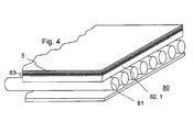
- Fig. 3 shows a further embodiment with multi-layered flame-pyrolytic layer 5.
- a flame-pyrolytic layer 5 with layers 51-56 were deposited by sequential coating with flames to which various metal-containing compounds were alternately added.
- the alternating layer produced in this way can act, inter alia, as an interference layer system and in this way has a mirror-effect, anti-reflection and / or coloring effect.
- sequentially silicate-containing layers and titanium oxide-containing layers can be produced by the addition of silane and titanium chloride flame-pyrolytic.
- Fig. 4 shows a solar thermal solar system 80 with an inventively coated solar glass 82 as a substrate 1.
- the solar system 80 has collector tubes 81, which are covered by the solar glass 82.
- the solar glass 82 has a multilayer anti-reflection layer 83 in order to reduce reflection losses.
- this layer 83 is covered on the substrate 1 with a silicon oxide-containing layer 5 deposited according to the invention by flame pyrolysis.
- the solar glass 83 are also provided on both sides with an antireflection coating and a flame-pyrolytic barrier layer.
- even a hydrophobic coating can be applied. Preference is given to this on the flame-pyrolytic layer 5 due to the connection to the surface hydroxyl groups of the layer 5 particularly well adhering silicate-containing and doped with fluoroalkylsilane Sol-gel layer with applied to the flame-pyrolytic layer 5.
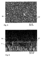
- FIGS. 5 and 6 are rasterelelektronische images of a coated with a flame-pyrolytically deposited layer glass-ceramic substrate shown. It shows Fig. 5 the coated surface in supervision and Fig. 6 a photograph of a fracture edge of the coated substrate. The magnification of these images is shown in the scale bar shown below.
- Fig. 5 The top view of the surface of the flame-pyrolytic layer was taken with an acceleration voltage of 5 kV at 200,000 magnification. This in Fig. 6 The image shown was taken at 300,000 magnification also with an acceleration voltage of 5 kV.
- Both images show that the surface 50 of the flame pyrolytic layer 5 as a whole has a granular structure with silicon oxide-containing grains 57.
- the grains detectable in the images more than 90% have a diameter smaller than 80 nanometers, even smaller than 60 micrometers, mostly up to 40 nanometers. Due to this fine-grained layer structure, a particularly large surface area is achieved with a structure that is not visually striking due to the small size of the grains.
Landscapes
- Chemical & Material Sciences (AREA)
- Engineering & Computer Science (AREA)
- Materials Engineering (AREA)
- Chemical Kinetics & Catalysis (AREA)
- General Chemical & Material Sciences (AREA)
- Organic Chemistry (AREA)
- Geochemistry & Mineralogy (AREA)
- Life Sciences & Earth Sciences (AREA)
- Physics & Mathematics (AREA)
- Plasma & Fusion (AREA)
- Mechanical Engineering (AREA)
- Metallurgy (AREA)
- Surface Treatment Of Glass (AREA)
- Laminated Bodies (AREA)
- Details Of Rigid Or Semi-Rigid Containers (AREA)
Abstract
Description
Die Erfindung betrifft eine Solarglas-Scheibe mit Barriere- oder Sperrschicht und die Herstellung einer Solarglas-Scheibe.The invention relates to a solar glass pane with barrier or barrier layer and the production of a solar glass pane.
Barriere- oder Sperrbeschichtungen von Gegenständen werden allgemein zur Versiegelung von Oberflächen, insbesondere zur Verhinderung oder Verlangsamung des Hindurchtretens von Atomen und Molekülen aus und in die Umgebung der Oberfläche eingesetzt. Entsprechend vielfältig sind die Anwendungen für derartige Beschichtungen. So werden Barriereschichten zum Beispiel bei Lebensmittelverpackungen eingesetzt, um eine möglichst hermetische Versiegelung der verpackten Nahrungsmittel und eine Verlängerung der Haltbarkeit zu erreichen.Barrier or barrier coatings of articles are commonly used to seal surfaces, particularly to prevent or slow the passage of atoms and molecules from and into the environment of the surface. Accordingly diverse are the applications for such coatings. For example, barrier layers are used in food packaging to achieve the most hermetic possible sealing of the packaged food and prolong shelf life.
Zur Herstellung dünner Sperrschichten kommen vielfach Vakuum- oder Niederdruck-Abscheideverfahren, wie Plasma-Deposition, Aufdampfen oder Sputterbeschichtung zum Einsatz. Diese Verfahren sind jedoch aufgrund der notwendigen Evakuierung kostenintensiv. Außerdem sind diese Verfahren auch nicht für jedes Substrat geeignet. Unter anderem ergeben sich Schwierigkeiten bei großformatigen Substraten, für die entsprechend große Vakuumkammern bereitgestellt werden müssten. Auch können Substrate, die im Vakuum stark ausgasen oder aufgrund von eingeschlossenen Gasmengen der mechanischen Belastung bei der Evakuierung nicht gewachsen sind, im allgemeinen nicht mit diesen Verfahren beschichtet werden.For the production of thin barrier layers, vacuum or low-pressure deposition methods such as plasma deposition, vapor deposition or sputter coating are used in many cases. However, these methods are costly due to the necessary evacuation. In addition, these methods are not suitable for every substrate. Among other things, difficulties arise with large format substrates for which correspondingly large vacuum chambers would have to be provided. Also, substrates that are outgassed in vacuum or trapped due to trapped Gas quantities are not equal to the mechanical load during evacuation, generally not be coated with these methods.
Andererseits weisen die mit diesen Verfahren herstellbaren Beschichtungen auch bei sehr geringen Schichtdicken im Nanometer- oder Mikrometer-Bereich bereits sehr hohe Barrierewirkungen auf.On the other hand, the coatings that can be produced with these methods already have very high barrier effects even with very small layer thicknesses in the nanometer or micrometer range.
Aus der
Es besteht daher Bedarf, Barrierebeschichtungen mit zumindest vergleichbaren Eigenschaften auch ohne den Einsatz von Vakuumbeschichtungsanlagen und ohne die sich dadurch oder bei der Pyrolyse auf heißen Oberflächen ergebenden Einschränkungen hinsichtlich der Wahl der Substratmaterialien und Substratabmessungen verwenden und herstellen zu können.There is therefore a need to be able to use and produce barrier coatings having at least comparable properties even without the use of vacuum coating systems and without the resulting restrictions or the pyrolysis on hot surfaces with regard to the choice of substrate materials and substrate dimensions.
Diese Aufgabe wird bereits in höchst überraschend einfacher Weise durch eine Solarglas-Scheibe und ein Verfahren zu deren Herstellung gemäß den unabhängigen Ansprüchen gelöst. Vorteilhafte Ausgestaltungen und Weiterbildungen sind Gegenstand der jeweiligen Unteransprüche.This object is already achieved in a surprisingly simple manner by a solar glass pane and a method for their preparation according to the independent claims. Advantageous embodiments and further developments are the subject of the respective subclaims.
Demgemäß sieht die Erfindung eine Solarglas-Scheibe mit einem Substrat und einer darauf angeordneten Barrierebeschichtung vor, wobei die Barrierebeschichtung eine flammpyrolytisch aufgebrachte Metalloxid-haltige Schicht umfaßt. Weiter umfasst die Solarglas-Scheibe eine Antireflex-Schicht, wobei die Antireflex-Schicht vorzugsweise auf der Barrierebeschichtung aufgebracht ist. Ein derartiges Erzeugnis ist erfindungsgemäß mit einem Verfahren zur Herstellung einer Solarglas-Scheibemit einer Barrierebeschichtung auf einem Substrat herstellbar, bei welchem zumindest ein Bereich der Oberfläche des Substrats mit einer Flamme überstrichen und eine metalloxidhaltige Schicht mittels Hydrolyse einer metallhaltigen Verbindung in der Flamme abgeschieden wird, während die Flamme den Bereich des Substrats überstreicht.Accordingly, the invention provides a solar glass panel having a substrate and a barrier coating disposed thereon, the barrier coating comprising a flame-retardant metal oxide-containing layer. Furthermore, the solar glass pane comprises an antireflection layer, wherein the antireflection layer is preferably applied to the barrier coating. According to the invention, such a product can be produced with a method for producing a solar glass pane with a barrier coating on a substrate, wherein at least a portion of the surface of the substrate is swept with a flame and a metal oxide-containing layer is deposited in the flame by means of hydrolysis of a metal-containing compound during the flame passes over the area of the substrate.
Im Unterschied zu dem aus der
Mittels der Erfindung können Barrierebeschichtungen hergestellt werden, welche in ihren Barriereeigenschaften zumindest vergleichbar zu aufgesputterten oder mittels Plasmabeschichtung abgeschiedenen Barriereschichten sind.
Im Unterschied zu diesen bekannten Verfahren zur Herstellung von Barriereschichten ist erfindungsgemäß aber keine Evakuierung der Umgebung des zu beschichtenden Substrats nötig. Die für Vakuumbeschichtungsverfahren, wie Sputtern, Aufdampfen oder plasmainduzierte Dampfphasenabscheidung notwendige Evakuierung ist aber ein wesentlicher Kostenfaktor, der bei der erfindungsgemäßen Beschichtung entfallen kann. Auch können erfindungsgemäß beispielsweise sehr großflächige Substrate problemlos mit einer Barrierebeschichtung versehen werden, die ansonsten in einer entsprechend großvolumigen und damit teuren Vakuumbeschichtungsanlage aufgebracht werden müßten.Barrier coatings can be produced by means of the invention which, at least comparable to sputtered or by means of their barrier properties Plasma coating deposited barrier layers are.
In contrast to these known processes for the preparation of barrier layers, according to the invention, however, no evacuation of the environment of the substrate to be coated is necessary. However, the evacuation necessary for vacuum coating processes, such as sputtering, vapor deposition or plasma-induced vapor deposition is a significant cost factor which can be omitted in the coating according to the invention. Also according to the invention, for example, very large substrates can be easily provided with a barrier coating, which would otherwise have to be applied in a correspondingly large-volume and therefore expensive vacuum coating system.
Von den mit Vakuumabscheideverfahren abgeschiedenen Schichten unterscheiden sich die erfindungsgemäßen flammpyrolytisch aufgebrachten, beziehungsweise abgeschiedenen Schichten im allgemeinen bereits dadurch, daß die flammpyrolytischen Schichten OH-Gruppen aufweisen. Insbesondere befinden sich solche Hydroxylgruppen auch an der Oberfläche der Schicht. Damit wird neben einer für die Barriereeigenschaften dichten Struktur außerdem noch eine Oberfläche mit einer hohen Oberflächenenergie und funktionellen Gruppen geschaffen, die eine gute Anbindung weiterer Moleküle erlauben. Dementsprechend eignen sich die erfindungsgemäßen Schichten unter anderem gleichzeitig noch besonders gut für eine Weiterverarbeitung, wie etwa für das Aufbringen weiterer Beschichtungen, die auf den erfindungsgemäßen Schichten besonders gut haften.Of the layers deposited by means of vacuum deposition processes, the flame-pyrolytically applied or deposited layers according to the invention generally already differ in that the flame-pyrolytic layers have OH groups. In particular, such hydroxyl groups are also on the surface of the layer. In addition to a structure that is dense for the barrier properties, a surface with a high surface energy and functional groups is also created, which allows a good connection of other molecules. Accordingly, the layers according to the invention are, inter alia, also particularly well suited for further processing, for example for the application of further coatings which adhere particularly well to the layers according to the invention.
Durch die hohe Oberflächenenergie wird außerdem auch eine wirkungsvolle Antibeschlag-Wirkung erzeugt.The high surface energy also creates an effective anti-fogging effect.
Gemäß einer bevorzugten Ausführungsform der Erfindung wird eine silikathaltige flammpyrolytisch aufgebrachte Schicht hergestellt. Eine derartige Schicht kann hergestellt werden, indem eine silikathaltige Schicht durch Hydrolyse einer Siliziumverbindung in der Flamme abgeschieden wird. Geeignete Siliziumverbindungen dazu sind unter anderem Hexamethyldisiloxan (HMDSO), Hexamethyldisilazan (HMDSN), Tetramethoxysilan, Tetraethoxysilan.According to a preferred embodiment of the invention, a silicate-containing flame-pyrolytically applied layer is produced. Such a layer can be made by depositing a silicate-containing layer by hydrolysis of a silicon compound in the flame. Suitable silicon compounds include hexamethyldisiloxane (HMDSO), hexamethyldisilazane (HMDSN), tetramethoxysilane, tetraethoxysilane.
Zusätzlich oder alternativ können der flammpyrolytischen, beziehungsweise flammpyrolytisch aufgebrachten Schicht vorteilhafte funktionelle Eigenschaften verliehen werden, wenn die flammpyrolytische Schicht ein Oxid zumindest eines der Metalle Titan, Aluminium, Zirkonium, Zinn, Indium enthält, indem bei der Abscheidung der Schicht in der Flamme eine Verbindung eines der Metalle Titan, Aluminium, Zirkonium, Zinn, Indium hydrolysiert wird. Diese Metalloxide können, auch in Verbindung mit Siliziumoxid, beziehungsweise Silikat in der flammpyrolytischen Schicht, auch gemischt vorliegen. Aus Mischungen von derartigen Metalloxiden, beziehungsweise, können beispielsweise sehr harte und/oder feuchtebeständige und/oder leitfähige Schichten erzeugt werden. Als Mischung wird im Sinne der Erfindung auch eine Dotierung verstanden. So kann unter anderem eine silikathaltige flammpyrolytische Schicht mit einem anderen Metalloxid, beispielsweise einem oder mehreren Oxiden der vorgenannten Metalle, dotiert werden, um zusätzliche funktionelle Eigenschaften zu erhalten und/oder die Barriereeigenschaften der flammpyrolytischen Schicht zu verbessern. So eignet sich beispielsweise Zinnoxid als wärmereflektierende Schicht.Additionally or alternatively, the flame-pyrolytic or flame-pyrolytically applied layer can be given advantageous functional properties if the flame-pyrolytic layer contains an oxide of at least one of the metals titanium, aluminum, zirconium, tin, indium, by forming a compound of a layer in the flame during the deposition of the layer the metals titanium, aluminum, zirconium, tin, indium is hydrolyzed. These metal oxides can also be mixed, also in combination with silicon oxide or silicate in the flame-pyrolytic layer. From mixtures of such metal oxides, or, for example, very hard and / or moisture-resistant and / or conductive layers can be produced. As a mixture in the context of the invention, a doping is understood. Thus, inter alia, a silicate-containing flame-pyrolytic layer can be doped with another metal oxide, for example one or more oxides of the aforementioned metals, in order to obtain additional functional properties and / or to improve the barrier properties of the flame-pyrolytic layer. For example, tin oxide is suitable as a heat-reflecting layer.
Eine erfindungsgemäße flammpyrolytische Schicht kann auch ein mit anderen Materialien gemischtes oder dotiertes Metalloxid enthalten. Ein vorteilhaftes Beispiel für eine flammpyrolytisch abgeschiedene Schicht mit zusätzlichen funktionellen Eigenschaften ist eine Zinnoxid-haltige flammpyrolytische Schicht, welche mit Fluor und/oder Indium dotiert ist. Eine derartige Schicht eignet sich beispielsweise als leitfähige transparente Schicht oder zu ihren wärmereflektierenden Eigenschaften auch zur Reduzierung der statischen Aufladung von Oberflächen .A flame-pyrolytic layer of the invention may also contain a metal oxide mixed or doped with other materials. An advantageous example of a flame-pyrolytically deposited layer with additional functional properties is a tin-oxide-containing flame-pyrolytic layer which is doped with fluorine and / or indium. Such a layer is suitable, for example, as a conductive transparent layer or for its heat-reflecting properties also for reducing the static charge of surfaces.
Verschiedene flammpyrolytisch abgeschiedene Oxide können nicht nur in einer Schicht miteinander gemischt werden. Es ist gemäß einer Weiterbildung der Erfindung auch daran gedacht, eine mehrlagige flammpyrolytische Schicht abzuscheiden. Durch einen mehrschichtigen oder mehrlagigen Aufbau können unter anderem optische Effekte, wie beispielsweise Ver- oder Entspiegelungen und/oder Farbortverschiebungen erreich werden. Selbstverständlich kann auch das Verfahren der Abscheidung mittels der flammpyrolytischen Beschichtung auch mit anderen Beschichtungsverfahren kombiniert werden, um eine mehrlagige Funktionalschicht zu erhalten.Various flame-pyrolytically deposited oxides can not only be mixed together in one layer. It is also according to a development of the invention also intended to deposit a multilayer flame-pyrolytic layer. By means of a multilayer or multilayer structure, optical effects such as, for example, antireflective or antireflective coatings and / or chromaticity shifts can be achieved. Of course, the method of deposition by means of the flame-pyrolytic coating can also be combined with other coating methods in order to obtain a multilayer functional layer.
Sogar eine Gradientenschicht mit kontinuierlich variierender Zusammensetzung in Richtung senkrecht zur Oberfläche kann erfindungsgemäß flammpyrolytisch abgeschieden werden. Flammpyrolytische Schichten mit einer Mischung verschiedener Oxide können beispielsweise durch Überstreichen des Substrats mit einer Flamme und Abscheiden einer metalloxidhaltigen Schicht mittels Hydrolyse mehrerer metallhaltiger Verbindungen in der Flamme abgeschieden werden. Auch kann die Oberfläche sequentiell mit Flammen überstrichen werden, denen jeweils unterschiedliche metallhaltige Verbindungen zugeführt werden, um eine flammpyrolytische Beschichtung abzuscheiden, die verschiedene Oxide enthält. Letzteres Verfahren eignet sich insbesondere auch zur Abscheidung mehrlagiger flammpyrolytischer Schichten. Ein sequentielles Überstreichen der Oberfläche kann beispielsweise mittels mehrerer hintereinander angeordneter Brenner erreicht werden, an welchen das Substrat vorbeibewegt wird, und/oder mit welchen das Substrat überstrichen wird.Even a gradient layer with continuously varying composition in the direction perpendicular to the surface can be deposited by flame pyrolysis according to the invention. Flammpyrolytische layers with a mixture of different oxides, for example, by sweeping the substrate with a flame and depositing a metal oxide-containing layer by hydrolysis of several metal-containing compounds are deposited in the flame. Also, the surface may be swept sequentially with flames, to each of which different metal-containing compounds are supplied to deposit a flame-pyrolytic coating containing various oxides. The latter method is particularly suitable for depositing multilayer flame pyrolytic layers. A sequential sweeping of the surface can be achieved, for example, by means of a plurality of successively arranged burners, on which the substrate is moved past, and / or with which the substrate is swept over.
Eine Kombination von Eigenschaften lässt sich durch eine Mischung von Precursor-Gasen über eine Flamme oder durch mehrere Flammen hintereinander angeordnet mit unterschiedlichen geeigneten Metalloxid-haltigen Verbindungen erreichen. Aus Mischungen von Metalloxiden, z.B. mit Metallen wie Si, Ti, Al, Zr, Sn, In, Sb können beispielsweise sehr harte und/oder feuchtebeständige und/oder leitfähige Schichten erzeugt werden.A combination of properties can be achieved by a mixture of precursor gases via a flame or by several flames arranged in series with different suitable metal oxide-containing compounds. From mixtures of metal oxides, e.g. With metals such as Si, Ti, Al, Zr, Sn, In, Sb, for example, very hard and / or moisture-resistant and / or conductive layers can be produced.
Bevorzugt wird weiterhin ein Methan, Propan- oder Butan enthaltendes Brenngas zur Erzeugung der Flamme verwendet. Diese Gase sind als Brenngas vergleichsweise kostengünstig und erzeugen ausreichende Flammentemperaturen. Die Verbrennung kann an Luft oder mittels separat zugeführtem Sauerstoff erfolgen.Preference is also given to using a methane, propane or butane-containing fuel gas to produce the flame. These gases are relatively inexpensive as fuel gas and produce sufficient flame temperatures. The combustion can be carried out in air or by means of separately supplied oxygen.
Um eine möglichst vollständige Hydrolyse der metallhaltigen Verbindung in der Flamme zu erreichen, hat es sich weiterhin als vorteilhaft erwiesen, wenn eine Flamme mit einem oxidierenden und einem reduzierenden Teil erzeugt und das Substrat nur mit dem oxidierenden Teil überstrichen wird. Eine weitere Maßnahme ist, ein eine reduzierende Komponente, vorzugsweise Wasserstoff oder Kohlenmonoxid enthaltendes Brenngas zur Erzeugung der Flamme zu verwenden.In order to achieve the fullest possible hydrolysis of the metal-containing compound in the flame, it has also proven to be advantageous if a flame with produced an oxidizing and a reducing part and the substrate is coated only with the oxidizing part. Another measure is to use a fuel component containing a reducing component, preferably hydrogen or carbon monoxide, to produce the flame.
Es hat sich überraschend gezeigt, daß bereits sehr dünne flammpyrolytische Schichten gute Barriereeigenschaften aufweisen. So weisen bereits Schichtdicken einer erfindungsgemäß flammpyrolytisch abgeschiedenen Barrierebeschichtung von 1 bis 100 Nanometern, bevorzugt 4 bis 40 Nanometern, oder sogar von höchstens 20 Nanometern sehr gute Barrierewirkungen auf.It has surprisingly been found that even very thin flame-pyrolytic layers have good barrier properties. Thus, layer thicknesses of a barrier coating of the flame-pyrolytically deposited barrier coating of from 1 to 100 nanometers, preferably from 4 to 40 nanometers, or even at most 20 nanometers, have very good barrier effects.
Weiterhin zeigt sich, daß mit der flammpyrolytischen Abscheidung eine körnige Oberflächenstruktur mit Körnern auf der Oberfläche der abgeschiedenen Schicht mit einem in Aufsicht betrachteten Durchmesser bis höchstens 80 Nanometer, vorzugsweise bis höchstens 60 Nanometer erzeugt werden kann. Dabei sind die Körner auf der Oberfläche einer dichten flammpyrolytischen Schicht angeordnet. Bei einer solchen Schicht wird als Schichtdicke die Schichtdicke der dichten Schicht ohne den darauf angeordneten Körnern verstanden.Furthermore, it can be seen that with the flame pyrolytic deposition a granular surface structure can be produced with grains on the surface of the deposited layer with a diameter viewed in plan view of at most 80 nanometers, preferably up to 60 nanometers. The grains are arranged on the surface of a dense flame-pyrolytic layer. In such a layer, the layer thickness is understood to mean the layer thickness of the dense layer without the grains arranged thereon.
Eine derartige Schichtstruktur wurde insbesondere bei einer Siliziumoxid-haltigen Schicht gefunden. Es wird dabei nicht ausgeschlossen, daß sich auch einzelne Körner mit noch größeren Durchmessern auf der Oberfläche finden. Beispielsweise kann es zu einer Agglomeration mehrerer Körner kommen, welche im Mikroskop dann unter Umständen wie ein einzelnes Korn erscheinen können. Jedenfalls weisen bei erfindungsgemäßen Schichten gemäß dieser Ausführungsform der Erfindung mehr als 90% der bei 200000-facher Vergrößerung im Rasterelektronenmikroskop erkennbaren Körner einem Durchmesser bis höchstens 80 Nanometer, vorzugsweise bis höchstens 60 Nanometer auf. Im allgemeinen weisen die Körner überwiegend Durchmesser bis 40 Nanometer auf. Auch können sich größere Körner mit größerem Durchmesser erkennbar aus solchen kleineren, agglomerierten Körnern zusammensetzen. Diese Schichten ermöglichen unter anderem eine besonders gut haftende Beschichtung mit weiteren Schichten, da durch die körnige Struktur einer derart abgeschiedenen Schicht eine sehr große Oberfläche erreicht werden kann. Außerdem kann die Empfindlichkeit gegen ein Verkratzen herabgesetzt werden.Such a layer structure was found especially in a silicon oxide-containing layer. It is not excluded that also find individual grains with even larger diameters on the surface. For example, there may be an agglomeration of several grains, which then under certain circumstances in the microscope a single grain can appear. In any case, in inventive layers according to this embodiment of the invention more than 90% of the detectable at 200,000 magnification in the scanning electron microscope grains have a diameter of at most 80 nanometers, preferably up to at most 60 nanometers. In general, the grains predominantly have diameters up to 40 nanometers. Also larger grains of larger diameter can be seen to be composed of such smaller, agglomerated grains. Among other things, these layers enable a particularly well-adhering coating with further layers, since a very large surface area can be achieved by the granular structure of such a deposited layer. In addition, the sensitivity to scratching can be lowered.
Gemäß einer Ausführungsform der Erfindung ist vorgesehen, ein Glas- oder Glaskeramiksubstrat mit der flammpyrolytischen Beschichtung zu versehen. Obwohl Glas oder Glaskeramik selbst im allgemeinen bereits gute Barriereeigenschaften aufweist, kann eine erfindungsgemäße zusätzliche Barrierebeschichtung überraschend dennoch die Produkteigenschaften verbessern. Als Barrierebeschichtung auf Glas- oder Glaskeramik ist es insbesondere möglich, die Diffusion von Ionen oder Molekülen aus oder in das Substrat zu verhindern. Beispielsweise kann es beim Tempern oder allgemein einer Erhitzung des Substrats zu einer unerwünschten Diffusion von Substratkomponenten aus dem Substrat oder auch von Komponenten weiterer darauf aufgebrachter Beschichtungen kommen.According to one embodiment of the invention, it is provided to provide a glass or glass-ceramic substrate with the flame-pyrolytic coating. Although glass or glass ceramic itself generally already has good barrier properties, an additional barrier coating according to the invention can surprisingly improve the product properties. As a barrier coating on glass or glass ceramic, it is particularly possible to prevent the diffusion of ions or molecules from or into the substrate. For example, annealing or generally heating the substrate may result in undesirable diffusion of substrate components from the substrate or even components of other coatings applied thereto.
Eine weitere Anwendung ist der Korrosionsschutz von Glas- oder Glaskeramik-Artikeln gegenüber aggressiven Gasen und/oder Verbrennungsprodukten. Die Erfindung eignet sich dementsprechend hervorragend auch für gasbeheizte Glaskeramik-Kochfelder, die insbesondere einem direkten Kontakt mit schwefelhaltigen Brenngasen ausgesetzt sind.Another application is the corrosion protection of glass or glass ceramic articles against aggressive gases and / or combustion products. Accordingly, the invention is also outstandingly suitable for gas-heated glass-ceramic cooktops which are exposed in particular to direct contact with sulfur-containing fuel gases.
Noch eine weitere bevorzugte Anwendung ist eine erfindungsgemäße flammpyrolytische Barrierebeschichtung auf Kalknatronglas, um die Diffusion von Alkalien aus dem Glas zu verhindern. Unerwünschte Wechselwirkungen von Alkalien mit Medikamenten oder weiteren funktionellen Schichten können so wirkungsvoll und in überraschend einfacher Weise vermindert werden.Yet another preferred application is a flame-pyrolytic barrier coating of the invention on soda-lime glass to prevent the diffusion of alkalis from the glass. Undesirable interactions of alkalis with drugs or other functional layers can be so effectively and surprisingly easily reduced.
Allgemein bewirkt eine derartige flammpyrolytische Sperr- oder Barriereschicht auch eine Versiegelung einer Substrat- oder Schichtoberfläche gegen Wechselwirkung mit Verdampfungskomponenten und/oder Partikel aus einer "Temperumgebung", also bei einem Einsatz des Gegenstands bei hohen Temperaturen. Die erfindungsgemäße Beschichtung bietet Schutz vor einer Degradation von Solargläsern. Als Solargläser werden im Sinne der Erfindung Gläser bezeichnet, die in Solaranlagen -sowohl solarthermische als auch photovoltaische Anlagen- eingesetzt werden.In general, such a flame-pyrolytic barrier layer also effects a sealing of a substrate or layer surface against interaction with evaporation components and / or particles from a "tempering environment", ie when the article is used at high temperatures. The coating according to the invention offers protection against a degradation of solar glasses. For the purposes of the invention, solar glasses are glasses which are used in solar systems-both solar thermal and photovoltaic systems.
Überraschend können nicht nur vergleichsweise temperaturbeständige Substrate, wie unter anderem die erwähnten Glas- oder Glaskeramik-Substrate beschichtet werden. Es ist auch möglich, Metall- oder Kunststoffsubstrate zu beschichten. Sogar Kunststofffolien können ohne eine Beschädigung durch die Flammbeaufschlagung zur Abscheidung der flammpyrolytischen Schicht mit einer Barrierebeschichtung versehen werden.Surprisingly, not only relatively temperature-resistant substrates, such as, inter alia, the aforementioned glass or glass ceramic substrates are coated. It is also possible, metal or Coating plastic substrates. Even plastic films can be provided with a barrier coating without damage from flame exposure to deposit the flame pyrolytic layer.
Ähnlich wie bei der Herstellung von Glaskeramik kann eine erfindungsgemäße flammpyrolytische Beschichtung als hochschmelzende Schicht auch bei Kunststoffsubstraten bei nachfolgenden Verarbeitungsschritten -gedacht ist hier insbesondere an die Heißformgebung- das Ankleben an Unterlagen oder Formen verhindern.Similar to the production of glass-ceramics, a flame-pyrolytic coating according to the invention as a high-melting layer can also be prevented in the case of plastic substrates during subsequent processing steps-in particular in hot forming-adhesion to substrates or molds.
Eine Weiterbildung der Erfindung sieht vor, daß dem Brenngas eine metallorganische Verbindung zugesetzt wird, welches durch Hydrolyse ein leitendes oder halbleitendes Oxid ergibt. Damit kann eine flammpyrolytische Schicht erzeugt werden, welche ein leitendes oder halbleitendes Oxid enthält. Derartige Schichten, beispielsweise in Form einer Silikat-, beziehungsweise Siliziumoxidschicht, welche ein halbleitendes oder leitendes Oxid enthält, können zusätzlich zu einer Barrierewirkung auch zur Vermeidung statischer Aufladungen dienen. Beispielsweise kann eine flammpyrolytische Schicht abgeschieden werden, die Zinnoxid enthält. Dazu kann dem Brenngas entsprechend eine zinnhaltige Verbindung, beispielsweise Zinnchlorid oder eine Zinn enthaltende organische Substanz zugesetzt werden.A development of the invention provides that an organometallic compound is added to the fuel gas, which results in a conductive or semiconductive oxide by hydrolysis. Thus, a flame pyrolytic layer containing a conductive or semiconducting oxide can be produced. Such layers, for example in the form of a silicate or silicon oxide layer, which contains a semiconductive or conductive oxide, can also serve to avoid static charges in addition to a barrier effect. For example, a flame-pyrolytic layer containing tin oxide may be deposited. For this purpose, a tin-containing compound, for example tin chloride or a tin-containing organic substance can be added to the fuel gas accordingly.
Die Eigenschaften und Einsatzmöglichkeiten erfindungsgemäß herstellbarer Gegenstände können auch durch weitere funktionelle Schichten vorteilhaft erweitert werden. So kann vorteilhaft zumindest eine weitere funktionelle Schicht aufgebracht werden, welche , wenigstens einer der Eigenschaften -elektrisch leitend, -Infrarotreflektierend, -Kratzschutz, -Antireflex, -Verspiegelung, - photokatalytisch, -Farbgebend, -antimikrobiell aufweist. Die funktionelle Schicht kann auf der flammpyrolytischen Barriereschicht, oder die flammpyrolytische Barriereschicht auf der weiteren funktionellen Schicht aufgebracht werden.The properties and possible uses of articles which can be produced according to the invention can also advantageously be extended by further functional layers. Thus, advantageously at least one further functional layer can be applied, which, at least one of the Properties -elektrisch leitend, -Infraredreflective, -Kratzschutz, -Antireflex, -Verspiegelung, - photocatalytic, -Colorful, -antimikrobiell has. The functional layer can be applied to the flame-pyrolytic barrier layer or the flame-pyrolytic barrier layer to the further functional layer.
Ein weiteres vorteilhaftes Beispiel für eine funktionelle Schicht ist eine Indium-Zinn-Oxidschicht. Derartige Schichten werden vielfach als transparente leitfähige Schichten eingesetzt. In Kombination mit einer solchen transparenten leitfähigen Schicht ergibt sich außerdem ein weiterer Vorteil der Erfindung. Indium-Zinn-Oxid (ITO) zeigt schlechte Hafteigenschaften, welche sich sowohl in einer schlechten Haftung des ITO auf dem Substrat, als auch in einer schlechten Haftung von auf einer ITO-Schicht aufgebrachten Schichten äußert. Durch die Eigenschaft der erfindungsgemäßen flammpyrolytischen Schicht, aufgrund der vorhandenen Hydroxylgruppen eine gute Anbindung zu bewirken, kann die flammpyrolytische Barrierebeschichtung gleichzeitig als Haftvermittler für die ITO-Schicht dienen. Wird eine flammpyrolytische Barriereschicht vor der ITO-Schicht auf dem Substrat abgeschieden, so ergibt sich eine verbesserte Haftung des darauf aufgebrachten ITO. Ebenso kann eine bessere Haftung nachfolgender Schichten auf eine mit ITO beschichteten Substrat erreicht werden, wenn vorher eine flammpyrolytische Barriereschicht als Haftvermittler abgeschieden wird.Another advantageous example of a functional layer is an indium tin oxide layer. Such layers are widely used as transparent conductive layers. In combination with such a transparent conductive layer also results in a further advantage of the invention. Indium-tin-oxide (ITO) shows poor adhesion properties, which manifests itself in both poor adhesion of the ITO to the substrate and in poor adhesion of layers deposited on an ITO layer. Due to the property of the flame-pyrolytic layer according to the invention, due to the presence of hydroxyl groups to bring about a good connection, the flame-pyrolytic barrier coating can simultaneously serve as an adhesion promoter for the ITO layer. If a flame-pyrolytic barrier layer is deposited on the substrate before the ITO layer, this results in improved adhesion of the ITO applied thereto. Likewise, better adhesion of subsequent layers to a substrate coated with ITO can be achieved if a flame-pyrolytic barrier layer is previously deposited as adhesion promoter.
Eine weitere Ausführungsform der Erfindung sieht vor, daß das Substrat mit einer hydrophoben Beschichung beschichtet wird. Gemäß einer bevorzugten Weiterbildung wird dazu eine Silikat-haltige Schicht mit einer hydrophoben Komponente, insbesondere eine Fluorverbindung, bevorzugt Fluoralkylsilan verwendet. Es hat sich insbesondere auch hier als besonders vorteilhaft erwiesen, wenn die hydrophoben Beschichung auf der flammpyrolytischen Beschichtung aufgebracht wird. Eine derartige Schichtanordnung führt zu besonders beständigen hydrophoben Schichten. Derartige Beschichtungen können beispielsweise leicht reinigbare Oberflächen schaffen.Another embodiment of the invention provides that the substrate is coated with a hydrophobic coating. According to a preferred embodiment of this is a Silicate-containing layer with a hydrophobic component, in particular a fluorine compound, preferably fluoroalkylsilane used. In particular, it has also proved to be particularly advantageous here if the hydrophobic coating is applied to the flame-pyrolytic coating. Such a layer arrangement leads to particularly resistant hydrophobic layers. For example, such coatings can provide easily cleanable surfaces.
Das Aufbringen der hydrophoben Beschichtung umfaßt demgemäß in bevorzugter Weiterbildung auch das Aufbringen eines Silikat-haltigen Sol-Gels auf der flammpyrolytischen Schicht, wobei das Sol-Gel eine hydrophoben Komponente, insbesondere eine Fluorverbindung, bevorzugt Fluoralkylsilan enthält.The application of the hydrophobic coating accordingly also comprises, in a preferred development, the application of a silicate-containing sol-gel on the flame-pyrolytic layer, wherein the sol-gel contains a hydrophobic component, in particular a fluorine compound, preferably fluoroalkylsilane.
Im folgenden wird die Erfindung anhand von Ausführungsbeispielen und unter Bezugnahme auf die Zeichnungen näher erläutert, wobei gleiche und ähnliche Elemente mit gleichen Bezugszeichen versehen sind und die Merkmale verschiedener Ausführungsbeispiele miteinander kombiniert werden können.In the following the invention with reference to embodiments and with reference to the drawings is explained in more detail, wherein the same and similar elements are provided with the same reference numerals and the features of various embodiments can be combined.
Es zeigen:
- Fig. 1
- eine Anordnung und ein Verfahren gemäß eines Ausführungsbeispiels zur Herstellung eines erfindungsgemäßen flammpyrolytisch beschichteten Gegenstands,
- Fig. 2
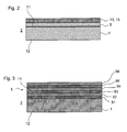
- Ausführungsbeispiele eines erfindungsgemäßen Gegenstands mit Indium-Zinn-Oxidschicht und hydrophober Beschichtung,
- Fig. 3
- ein Ausführungsbeispiel mit mehrlagiger flammpyrolytischer Beschichtung,
- Fig. 4
- eine Solaranlage mit erfindungsgemäß beschichtetem Solarglas, und
- Fig. 5 und 6
- rasterelektronenmikroskopische Aufnahmen einer flammpyrolytisch abgeschiedenen Barriereschicht.
- Fig. 1
- an arrangement and a method according to an embodiment for producing a flame-pyrolytically coated article according to the invention,
- Fig. 2
- Exemplary embodiments of an article according to the invention with indium tin oxide layer and hydrophobic coating,
- Fig. 3
- an embodiment with multilayer flame-pyrolytic coating,
- Fig. 4
- a solar system with the invention coated solar glass, and
- FIGS. 5 and 6
- Scanning electron micrographs of a flame-pyrolytically deposited barrier layer.
Zur Herstellung des Gegenstands wird ein flaches, scheibenförmiges Glassubstrat bereitgestellt. Als Substrat 1 kann, wie bei dem in
Das Metalloxid der flammpyrolytischen Schicht 5 kann insbesondere Siliziumoxid, beziehungsweise Silikat sein oder Silikat, beziehungsweise Siliziumoxid umfassen. Dazu wird den Flammen eine Siliziumverbindung zugeführt. Bevorzugt erfolgt die Zuführung durch Beimischung einer gasförmigen oder verdampfbaren Siliziumverbindung zum Brenngas. Als Brenngas wird bevorzugt ein Gas mit einer oder mehreren der Komponenten Wasserstoff, Methan, Propan, Butan eingesetzt. Die Verbrennung erfolgt an Luft. Alternativ oder zusätzlich kann auch Sauerstoff zugeführt werden.The metal oxide of the flame-
Durch die Hydrolyse der Siliziumverbindung in den Flammen 21 wird auf dem Substrat 1 dann eine flammpyrolytische silikathaltige Schicht 5 abgeschieden. Als Siliziumverbindung kann insbesondere Hexamethyldisiloxan (HMDSO), Hexamethyldisilazan (HMDSN) und/oder Tetraethoxysilan der Flamme zugeführt werden. Bevorzugt werden Silane, wie Tetraethoxysilan eingesetzt.By the hydrolysis of the silicon compound in the
Alternativ oder zusätzlich -je nachdem, welche funktionellen Eigenschaften die Schicht 5 erhalten soll, können auch eine oder mehrere Verbindungen mit den Metallen Titan, Aluminium, Zirkonium, Zinn, Indium den Flammen 22 zugesetzt werden, um durch Hydrolyse dieser Verbindungen Metalloxide dieser Metalle zu erhalten. Auch können auf diese Weise Mischoxide abgeschieden werden, wie etwa silikathaltige Schichten, welche mit einem oder mehreren Oxiden der Metalle Titan, Aluminium, Zirkonium, Zinn, Indium dotiert sind.Alternatively or additionally, depending on which functional properties the
Die Beschichtung mit verschiedenen Oxiden kann auch sequentiell erfolgen. Dazu kann das Substrat 1 mehrmals mit den Flammen 22 der Brennerbatterie 20 überstrichen werden, wobei jeweils andere metallhaltige Verbindungen zugesetzt und hydrolysiert werden. Auch können dazu mehrere Brennerbatterien hintereinander angeordnet werden, wobei in den jeweiligen Brennern der Brennerbatterien verschiedene Metalloxide hydrolysiert werden.The coating with different oxides can also be done sequentially. For this purpose, the
Es hat sich als bei der Beschichtung außerdem als vorteilhaft erwiesen, Flammen mit einem oxidierenden und einem reduzierenden Teil zu erzeugen und das Substrat nur mit dem oxidierenden Teil zu überstreichen. Damit wird eine möglichst vollständige Hydrolyse erreicht und die Einlagerung unvollständig verbrannter Brenngasbestandteile, wie beispielsweise von Kohlenwasserstoffen vermieden. Auch können dem Brenngas zur Unterstützung der Hydrolyse reduzierende Komponenten, wie Wasserstoff oder Kohlenmonoxid beigemischt werden.It has also proved advantageous in the coating to produce flames with an oxidizing and a reducing part and to coat the substrate only with the oxidizing part. This achieves as complete a hydrolysis as possible and prevents the incorporation of incompletely combusted fuel gas constituents, such as, for example, hydrocarbons. Also, fuel components such as hydrogen or carbon monoxide may be added to the fuel gas to assist in the hydrolysis.
Die für die Schichtdicke der Schicht 5 relevanten Beschichtungsparameter, wie unter anderem die Zusammensetzung des Brenngases mit Siliziumverbindung und die Geschwindigkeit des Vorbeiführens des Substrats 1 an den Flammen 22 werden so eingestellt, daß die flammpyrolytische Schicht 5 eine Schichtdicke von 1 bis 100 Nanometern, bevorzugt 4 bis 40 Nanometern, besonders bevorzugt höchstens 20 Nanometern aufweist. Selbst mit Schichtdicken unter 20 Nanometern kann in vielen Fällen noch eine ausreichende Barrierewirkung der Schicht 5 erzielt werden.The relevant for the layer thickness of the
Die erfindungsgemäße flammpyrolytische Schicht 5 kann außerdem die Stoßfestigkeit verbessern. Wird die Schicht 5 vor dem Keramisieren des Ausgangsglases aufgebracht, so kann ein Ankleben der Glasplatte beim Keramisieren auf der Keramisierungsunterlage vermieden werden. Damit werden auch Kratzer, die durch ein Ankleben, Schrumpfen und dadurch verursachten Ablösen der beim Keramisieren sehr weichen Platte von der Unterlage entstehen, vermieden. Da diese Kratzer die Stoßfestigkeit der fertig keramisierten Platte herabsetzen, kann eine verbesserte Festigkeit erzielt werden.The
Anhand von
Gemäß einem ersten Ausführungsbeispiel ist auf dieser Schicht 5 eine Indium-Zinn-Oxidschicht 13 abgeschieden worden. Das Abscheiden dieser Schicht 13 kann beispielsweise durch Sputtern erfolgen. Neben einer Barrierewirkung aufgrund der dichten Struktur der Schicht 5 wird außerdem eine Verbesserung der Hafteigenschaften der ITO-Schicht 13 erzielt, da die Schicht 5 an ihrer Oberfläche Hydroxylgruppen aufweist, mit welchen eine gute Bindung an das ITO erreicht wird. Aufgrund der guten Sperrwirkung der Schicht 5 und der Haftungsverbesserung kann das Substrat 1 beispielsweise auch ein Kunststoffsubstrat sein. Auch hier zeigen sich besondere Vorteile einer erfindungsgemäßen flammpyrolytischen Beschichtung, da insbesondere auf Kunststoff ITO ansonsten nur sehr schlecht haftet. Die meisten Kunststoffe haben überdies im allgemeinen nur schlechte Barriereeigenschaften, so daß die Schicht 5 hier zusätzlich einen wirksamen Schutz gegenüber durch das Substrat 1 hindurchdiffundierenden Bestandteilen, wie Wasser oder Sauerstoff bereitstellt.According to a first exemplary embodiment, an indium tin oxide layer 13 is deposited on this
Es ist außerdem daran gedacht, auch die Indium-Zinn-Oxidschicht 13 flammpyrolytisch abzuscheiden. Dazu kann die Seite 11 des Substrats 1 sequentiell mit Flammen überstrichen werden, wobei die silikathaltige Schicht 5 durch Zusatz einer Siliziumverbindung, beispielsweise ein Silan, zur Flamme zugesetzt und dann durch Überstreichen mit einer oder mehreren weiteren Flammen, denen Indium- und Zinnverbindungen zugesetzt werden, die Indium-Zinn-Oxidschicht 13 abgeschieden wird. Auf diese Weise wird dementsprechend eine mehrlagige flammpyrolytische Beschichtung erhalten. Eine Alternative zu einer derartigen Schicht 13 ist eine Fluor-dotierte Zinnoxidschicht, die ebenfalls flammpyrolytisch durch Hydrolyse von Zinn- und Fluorverbindungen herstellbar ist.It is also thought to deposit the indium tin oxide layer 13 by flame pyrolysis. For this purpose, the
Gemäß einem weiteren Ausführungsbeispiel wird auf der flammpyrolytischen Schicht 5 eine hydrophobe Beschichtung aufgebracht. Dazu wird bei dem in
Anstelle oder zusätzlich zur hydrophoben Schicht 15 und/oder der ITO-Schicht 13 können auch andere funktionelle Schichten aufgebracht werden. Beispielsweise kann eine infrarotreflektierende Zinnoxidschicht, oder eine harte Kratzschutzschicht, Interferenzschichten, wie beispielsweise eine Antireflexbeschichtung, eine Verspiegelungsschicht, eine photokatalytisch wirksame Schicht -beispielsweise eine Titanoxid-haltige Schicht und/oder eine farbgebende Schicht aufgebracht werden.Instead of or in addition to the hydrophobic layer 15 and / or the ITO layer 13, other functional layers can also be applied. For example, an infrared-reflective tin oxide layer, or a hard scratch-resistant layer, interference layers such as an antireflective coating, a mirroring layer, a photocatalytically active layer-for example, a titanium oxide-containing layer and / or a coloring layer can be applied.
Selbstverständlich kann, anders als in der vereinfachten Darstellung der
In weiterer Ausgestaltung kann wie anhand von
In den
Beide Bilder zeigen, daß die Oberfläche 50 der flammpyrolytischen Schicht 5 insgesamt eine körnige Struktur mit Siliziumoxid-haltigen Körnern 57 aufweist. Von den in den Aufnahmen erkennbaren Körnern weisen mehr als 90 % einen Durchmesser kleiner als 80 Nanometer, sogar kleiner als 60 Mikrometer, überwiegend bis 40 Nanometer auf. Aufgrund dieser feinkörnigen Schichtstruktur wird eine besonders große Oberfläche mit optisch aufgrund der geringen Größe der Körner nicht auffälliger Struktur erzielt. Die große Oberfläche in Verbindung mit den an der Oberfläche der Siliziumoxid-haltigen Schicht 5 zumindest in frisch abgeschiedenem Zustand in hoher Dichte vorhandenen OH-Gruppen sorgt für eine besonders gute Haftung nachfolgend aufgebrachter Materialien, wie etwa weiteren Schichten.Both images show that the
Es ist dem Fachmann ersichtlich, dass die Erfindung nicht auf die vorstehend beschriebenen Ausführungsformen beschränkt ist, sondern vielmehr in vielfältiger Weise variiert werden kann. Insbesondere können die Merkmale der einzelnen beispielhaften Ausführungsformen auch miteinander kombiniert werden.It will be apparent to those skilled in the art that the invention is not limited to the embodiments described above, but rather can be varied in many ways. In particular, the features of the individual exemplary embodiments may also be combined with each other.
Claims (15)
verwendet wird.
is used.
Applications Claiming Priority (2)
| Application Number | Priority Date | Filing Date | Title |
|---|---|---|---|
| DE200410053706 DE102004053706A1 (en) | 2004-11-03 | 2004-11-03 | Barrier coated article and method of making such article |
| EP05802295A EP1807371B1 (en) | 2004-11-03 | 2005-11-03 | Method for producing a glass-ceramic article with barrier layer |
Related Parent Applications (1)
| Application Number | Title | Priority Date | Filing Date |
|---|---|---|---|
| EP05802295.5 Division | 2005-11-03 |
Publications (2)
| Publication Number | Publication Date |
|---|---|
| EP2261185A2 true EP2261185A2 (en) | 2010-12-15 |
| EP2261185A3 EP2261185A3 (en) | 2013-10-02 |
Family
ID=35583338
Family Applications (2)
| Application Number | Title | Priority Date | Filing Date |
|---|---|---|---|
| EP05802295A Not-in-force EP1807371B1 (en) | 2004-11-03 | 2005-11-03 | Method for producing a glass-ceramic article with barrier layer |
| EP10010428.0A Ceased EP2261185A3 (en) | 2004-11-03 | 2005-11-03 | Solar glass panel with barrier coating and method for producing same |
Family Applications Before (1)
| Application Number | Title | Priority Date | Filing Date |
|---|---|---|---|
| EP05802295A Not-in-force EP1807371B1 (en) | 2004-11-03 | 2005-11-03 | Method for producing a glass-ceramic article with barrier layer |
Country Status (6)
| Country | Link |
|---|---|
| EP (2) | EP1807371B1 (en) |
| JP (1) | JP4955563B2 (en) |
| CN (1) | CN101151223B (en) |
| DE (1) | DE102004053706A1 (en) |
| ES (1) | ES2387498T3 (en) |
| WO (1) | WO2006048276A1 (en) |
Cited By (19)
| Publication number | Priority date | Publication date | Assignee | Title |
|---|---|---|---|---|
| US8512796B2 (en) | 2009-05-13 | 2013-08-20 | Si02 Medical Products, Inc. | Vessel inspection apparatus and methods |
| US9272095B2 (en) | 2011-04-01 | 2016-03-01 | Sio2 Medical Products, Inc. | Vessels, contact surfaces, and coating and inspection apparatus and methods |
| US9458536B2 (en) | 2009-07-02 | 2016-10-04 | Sio2 Medical Products, Inc. | PECVD coating methods for capped syringes, cartridges and other articles |
| US9545360B2 (en) | 2009-05-13 | 2017-01-17 | Sio2 Medical Products, Inc. | Saccharide protective coating for pharmaceutical package |
| US9554968B2 (en) | 2013-03-11 | 2017-01-31 | Sio2 Medical Products, Inc. | Trilayer coated pharmaceutical packaging |
| US9662450B2 (en) | 2013-03-01 | 2017-05-30 | Sio2 Medical Products, Inc. | Plasma or CVD pre-treatment for lubricated pharmaceutical package, coating process and apparatus |
| US9664626B2 (en) | 2012-11-01 | 2017-05-30 | Sio2 Medical Products, Inc. | Coating inspection method |
| US9764093B2 (en) | 2012-11-30 | 2017-09-19 | Sio2 Medical Products, Inc. | Controlling the uniformity of PECVD deposition |
| US9863042B2 (en) | 2013-03-15 | 2018-01-09 | Sio2 Medical Products, Inc. | PECVD lubricity vessel coating, coating process and apparatus providing different power levels in two phases |
| US9878101B2 (en) | 2010-11-12 | 2018-01-30 | Sio2 Medical Products, Inc. | Cyclic olefin polymer vessels and vessel coating methods |
| US9903782B2 (en) | 2012-11-16 | 2018-02-27 | Sio2 Medical Products, Inc. | Method and apparatus for detecting rapid barrier coating integrity characteristics |
| US9937099B2 (en) | 2013-03-11 | 2018-04-10 | Sio2 Medical Products, Inc. | Trilayer coated pharmaceutical packaging with low oxygen transmission rate |
| US10189603B2 (en) | 2011-11-11 | 2019-01-29 | Sio2 Medical Products, Inc. | Passivation, pH protective or lubricity coating for pharmaceutical package, coating process and apparatus |
| US10201660B2 (en) | 2012-11-30 | 2019-02-12 | Sio2 Medical Products, Inc. | Controlling the uniformity of PECVD deposition on medical syringes, cartridges, and the like |
| WO2019120879A1 (en) * | 2017-12-22 | 2019-06-27 | BSH Hausgeräte GmbH | Object with a high-temperature-resistant omniphobic non-stick coating, and method for producing such an object |
| US11066745B2 (en) | 2014-03-28 | 2021-07-20 | Sio2 Medical Products, Inc. | Antistatic coatings for plastic vessels |
| US11077233B2 (en) | 2015-08-18 | 2021-08-03 | Sio2 Medical Products, Inc. | Pharmaceutical and other packaging with low oxygen transmission rate |
| US11116695B2 (en) | 2011-11-11 | 2021-09-14 | Sio2 Medical Products, Inc. | Blood sample collection tube |
| US11624115B2 (en) | 2010-05-12 | 2023-04-11 | Sio2 Medical Products, Inc. | Syringe with PECVD lubrication |
Families Citing this family (23)
| Publication number | Priority date | Publication date | Assignee | Title |
|---|---|---|---|---|
| DE102006029617A1 (en) * | 2006-06-23 | 2007-12-27 | Verein zur Förderung von Innovationen durch Forschung, Entwicklung und Technologietransfer e.V. (Verein INNOVENT e.V.) | Process for modifying the surface properties of glass |
| DE102006045617B4 (en) * | 2006-09-22 | 2010-06-10 | Innovent E.V. Technologieentwicklung | Process for producing an inorganic-inorganic gradient composite layer |
| FR2907112B1 (en) * | 2006-10-16 | 2009-10-02 | Eurokera S N C Sa | VITROCERAMIC PLATE AND METHOD FOR MANUFACTURING THE SAME |
| EP1961835A1 (en) * | 2007-02-20 | 2008-08-27 | W & H Dentalwerk Bürmoos GmbH | Device for the modification of the surface-activity of in particular medical instruments |
| DE102007034683A1 (en) * | 2007-07-25 | 2009-01-29 | BSH Bosch und Siemens Hausgeräte GmbH | layer body |
| DE102007036796A1 (en) * | 2007-08-03 | 2009-02-05 | Rehau Ag + Co | Treating a pipe inner surface of a molded part such as plastic tube with reactive substances formed by combusting silanes in a separate combustion chamber, comprises guiding the formed reactive substances to the surface of the molded part |
| DE102007058927B4 (en) * | 2007-12-05 | 2010-04-29 | Schott Ag | Substrate with a sol-gel layer and method for producing a composite material and its use |
| DE102007058926B4 (en) * | 2007-12-05 | 2010-04-29 | Schott Ag | Solar glass and method for producing a solar glass and its use |
| DE102008030825A1 (en) | 2008-06-30 | 2009-12-31 | Schott Ag | Device for reflecting heat radiation, a method for its production and its use |
| DE102009018908B4 (en) * | 2009-04-28 | 2013-09-05 | Schott Ag | Composite material with a porous anti-reflection layer and process for its preparation |
| DE102009021272A1 (en) * | 2009-05-14 | 2010-11-18 | Schott Solar Ag | Method for producing a photovoltaic module |
| DE102010013038B4 (en) * | 2010-03-26 | 2012-01-19 | Schüco Tf Gmbh & Co. Kg | Method for producing a photovoltaic cell |
| GB201015657D0 (en) * | 2010-09-20 | 2010-10-27 | Pilkington Group Ltd | Coating glass |
| DE102011011543A1 (en) | 2011-02-17 | 2012-08-23 | Zwiesel Kristallglas Ag | Surface treatment glass product e.g. crystal glass product, involves depositing silicate-containing layer from portion of surface of glass product by pyrolyzing silicon compound in flame, and polishing glass product |
| DE102011076754A1 (en) * | 2011-05-31 | 2012-12-06 | Schott Ag | Substrate element for the coating with an easy-to-clean coating |
| DE102011076756A1 (en) * | 2011-05-31 | 2012-12-06 | Schott Ag | Substrate element for the coating with an easy-to-clean coating |
| CN103480553B (en) * | 2013-09-18 | 2015-03-25 | 苏州大学 | Method for manufacturing super-hydrophobic surface |
| DE102015101312A1 (en) * | 2015-01-29 | 2016-08-04 | Thyssenkrupp Steel Europe Ag | A method of applying a metallic protective coating to a surface of a steel product |
| CN107922257A (en) | 2015-09-02 | 2018-04-17 | 康宁股份有限公司 | Antimicrobial antireflective article and its manufacture method |
| US9970305B2 (en) * | 2015-09-18 | 2018-05-15 | General Electric Company | Treatment process, oxide-forming treatment composition, and treated component |
| FR3041740A1 (en) * | 2015-09-25 | 2017-03-31 | Valeo Vision | TRANSPARENT OPTICAL ELEMENT FOR MOTOR VEHICLE |
| US20230243060A1 (en) * | 2020-04-24 | 2023-08-03 | Novelis Inc. | Thermally modified oxide based pretreatments for metals and methods of making the same |
| KR102417793B1 (en) * | 2020-12-15 | 2022-07-14 | 포항공과대학교 산학협력단 | Composition for an organic-inorganic hybrid gas barrier film containing a fluorine-based precursor and amphiphilic legged structured polymeric alkoxysilane precursor and a gas barrier film using the same |
Citations (1)
| Publication number | Priority date | Publication date | Assignee | Title |
|---|---|---|---|---|
| US5165972A (en) | 1984-08-13 | 1992-11-24 | Pilkington Plc | Coated glass |
Family Cites Families (23)
| Publication number | Priority date | Publication date | Assignee | Title |
|---|---|---|---|---|
| NL120195C (en) * | 1958-08-27 | |||
| DE3403894C1 (en) * | 1984-02-04 | 1985-07-25 | Kulzer & Co GmbH, 6393 Wehrheim | Device for coating a metallic dental prosthesis part and method for operating such a device |
| DD256151B5 (en) * | 1984-10-03 | 1995-05-18 | Tiller Hans Juergen | Method for producing surface layers |
| DD236516A1 (en) * | 1985-04-24 | 1986-06-11 | Werk Fernsehelektronik Veb | GENERATION OF TRANSPARENT ELECTRICALLY CONDUCTIVE MODIFICATIONS ON SILICATE SUBSTRATES |
| DE3936654C1 (en) * | 1989-11-03 | 1990-12-20 | Schott Glaswerke, 6500 Mainz, De | |
| US5114846A (en) * | 1990-10-23 | 1992-05-19 | Shin-Etsu Bio, Inc. | Process for producing streptovaricin |
| DE4237921A1 (en) * | 1992-10-23 | 1994-04-28 | Flachglas Ag | Method and device for modifying the surface activity of a silicate glass substrate |
| US5959787A (en) * | 1995-06-06 | 1999-09-28 | The Boeing Company | Concentrating coverglass for photovoltaic cells |
| DE19538515A1 (en) * | 1995-10-05 | 1997-04-10 | Fraunhofer Ges Forschung | Coating glass bottles etc. with hard polymer to prevent breakage |
| JP3454110B2 (en) * | 1996-11-18 | 2003-10-06 | 日本板硝子株式会社 | Water repellent glass |
| DE69710678T2 (en) | 1996-11-18 | 2002-08-01 | Nippon Sheet Glass Co Ltd | Water-repellent glass pane and process for its manufacture |
| DE19858933A1 (en) * | 1998-12-08 | 2000-06-15 | Gerald Hartwig | Water- and dirt-repellent coating for glass, e.g. window, metal, plastics or other heat-resistant material is produced by flame coating with silicon tetrafluoride and/or titanium tetrachloride in e.g. natural gas oxygen flame |
| DE19918811A1 (en) * | 1999-04-26 | 2000-11-02 | Fraunhofer Ges Forschung | Tempered safety glass with a smudge-proof, porous SiO¶2¶ anti-reflective layer u. Process z. d. Manufacturing |
| AU5783600A (en) * | 1999-07-02 | 2001-01-22 | Microcoating Technologies, Inc. | Method of coating ceramics using ccvd |
| ES2170608B1 (en) * | 1999-08-06 | 2003-10-01 | Ct E Investigaciones Energetic | PROCEDURE FOR THE FORMATION OF AN ANTIREFLECTANT AND LEVELING FILM ON GLASS / OCT SUBSTRATES. |
| MXPA02004955A (en) * | 1999-11-24 | 2002-09-18 | Ppg Ind Ohio Inc | Low shading coefficient and low emissivity coatings and coated articles. |
| DE10063265A1 (en) * | 1999-12-20 | 2001-07-05 | Murata Manufacturing Co | External covering substrate for electronic component such as piezoelectric resonator comprises multilayers which can be respectively sintered in liquid phase and different temperature |
| DE10019926A1 (en) * | 2000-04-20 | 2001-10-31 | Isimat Gmbh Siebdruckmaschinen | Method for modifying a surface of a compact substrate |
| US7351449B2 (en) * | 2000-09-22 | 2008-04-01 | N Gimat Co. | Chemical vapor deposition methods for making powders and coatings, and coatings made using these methods |
| JP4586263B2 (en) * | 2000-11-29 | 2010-11-24 | 旭硝子株式会社 | Substrate with conductive film and method for producing the same |
| DE10062187B4 (en) | 2000-12-14 | 2005-08-04 | Schott Ag | Use of a device for ceramizing the starting glass of a glass ceramic |
| DE10206330A1 (en) * | 2002-02-14 | 2003-08-28 | Dirk Rueter | Applying inorganic ceramic layers to a substrate comprises depositing ceramic particles or molecules with a phosphor composition from a flame to form a ceramic-like layer on a glass substrate |
| DE10236728A1 (en) * | 2002-08-09 | 2004-02-26 | Schott Glas | Easy to clean device |
-
2004
- 2004-11-03 DE DE200410053706 patent/DE102004053706A1/en not_active Ceased
-
2005
- 2005-11-03 WO PCT/EP2005/011752 patent/WO2006048276A1/en active Application Filing
- 2005-11-03 ES ES05802295T patent/ES2387498T3/en active Active
- 2005-11-03 EP EP05802295A patent/EP1807371B1/en not_active Not-in-force
- 2005-11-03 JP JP2007538362A patent/JP4955563B2/en active Active
- 2005-11-03 EP EP10010428.0A patent/EP2261185A3/en not_active Ceased
- 2005-11-03 CN CN200580037381XA patent/CN101151223B/en not_active Expired - Fee Related
Patent Citations (1)
| Publication number | Priority date | Publication date | Assignee | Title |
|---|---|---|---|---|
| US5165972A (en) | 1984-08-13 | 1992-11-24 | Pilkington Plc | Coated glass |
Cited By (37)
| Publication number | Priority date | Publication date | Assignee | Title |
|---|---|---|---|---|
| US10390744B2 (en) | 2009-05-13 | 2019-08-27 | Sio2 Medical Products, Inc. | Syringe with PECVD lubricity layer, apparatus and method for transporting a vessel to and from a PECVD processing station, and double wall plastic vessel |
| US8512796B2 (en) | 2009-05-13 | 2013-08-20 | Si02 Medical Products, Inc. | Vessel inspection apparatus and methods |
| US8834954B2 (en) | 2009-05-13 | 2014-09-16 | Sio2 Medical Products, Inc. | Vessel inspection apparatus and methods |
| US9572526B2 (en) | 2009-05-13 | 2017-02-21 | Sio2 Medical Products, Inc. | Apparatus and method for transporting a vessel to and from a PECVD processing station |
| US9545360B2 (en) | 2009-05-13 | 2017-01-17 | Sio2 Medical Products, Inc. | Saccharide protective coating for pharmaceutical package |
| US10537273B2 (en) | 2009-05-13 | 2020-01-21 | Sio2 Medical Products, Inc. | Syringe with PECVD lubricity layer |
| US9458536B2 (en) | 2009-07-02 | 2016-10-04 | Sio2 Medical Products, Inc. | PECVD coating methods for capped syringes, cartridges and other articles |
| US11624115B2 (en) | 2010-05-12 | 2023-04-11 | Sio2 Medical Products, Inc. | Syringe with PECVD lubrication |
| US9878101B2 (en) | 2010-11-12 | 2018-01-30 | Sio2 Medical Products, Inc. | Cyclic olefin polymer vessels and vessel coating methods |
| US11123491B2 (en) | 2010-11-12 | 2021-09-21 | Sio2 Medical Products, Inc. | Cyclic olefin polymer vessels and vessel coating methods |
| US9272095B2 (en) | 2011-04-01 | 2016-03-01 | Sio2 Medical Products, Inc. | Vessels, contact surfaces, and coating and inspection apparatus and methods |
| US11884446B2 (en) | 2011-11-11 | 2024-01-30 | Sio2 Medical Products, Inc. | Passivation, pH protective or lubricity coating for pharmaceutical package, coating process and apparatus |
| US11724860B2 (en) | 2011-11-11 | 2023-08-15 | Sio2 Medical Products, Inc. | Passivation, pH protective or lubricity coating for pharmaceutical package, coating process and apparatus |
| US11148856B2 (en) | 2011-11-11 | 2021-10-19 | Sio2 Medical Products, Inc. | Passivation, pH protective or lubricity coating for pharmaceutical package, coating process and apparatus |
| US10577154B2 (en) | 2011-11-11 | 2020-03-03 | Sio2 Medical Products, Inc. | Passivation, pH protective or lubricity coating for pharmaceutical package, coating process and apparatus |
| US10189603B2 (en) | 2011-11-11 | 2019-01-29 | Sio2 Medical Products, Inc. | Passivation, pH protective or lubricity coating for pharmaceutical package, coating process and apparatus |
| US11116695B2 (en) | 2011-11-11 | 2021-09-14 | Sio2 Medical Products, Inc. | Blood sample collection tube |
| US9664626B2 (en) | 2012-11-01 | 2017-05-30 | Sio2 Medical Products, Inc. | Coating inspection method |
| US9903782B2 (en) | 2012-11-16 | 2018-02-27 | Sio2 Medical Products, Inc. | Method and apparatus for detecting rapid barrier coating integrity characteristics |
| US9764093B2 (en) | 2012-11-30 | 2017-09-19 | Sio2 Medical Products, Inc. | Controlling the uniformity of PECVD deposition |
| US10363370B2 (en) | 2012-11-30 | 2019-07-30 | Sio2 Medical Products, Inc. | Controlling the uniformity of PECVD deposition |
| US11406765B2 (en) | 2012-11-30 | 2022-08-09 | Sio2 Medical Products, Inc. | Controlling the uniformity of PECVD deposition |
| US10201660B2 (en) | 2012-11-30 | 2019-02-12 | Sio2 Medical Products, Inc. | Controlling the uniformity of PECVD deposition on medical syringes, cartridges, and the like |
| US9662450B2 (en) | 2013-03-01 | 2017-05-30 | Sio2 Medical Products, Inc. | Plasma or CVD pre-treatment for lubricated pharmaceutical package, coating process and apparatus |
| US10912714B2 (en) | 2013-03-11 | 2021-02-09 | Sio2 Medical Products, Inc. | PECVD coated pharmaceutical packaging |
| US10016338B2 (en) | 2013-03-11 | 2018-07-10 | Sio2 Medical Products, Inc. | Trilayer coated pharmaceutical packaging |
| US9937099B2 (en) | 2013-03-11 | 2018-04-10 | Sio2 Medical Products, Inc. | Trilayer coated pharmaceutical packaging with low oxygen transmission rate |
| US11298293B2 (en) | 2013-03-11 | 2022-04-12 | Sio2 Medical Products, Inc. | PECVD coated pharmaceutical packaging |
| US11344473B2 (en) | 2013-03-11 | 2022-05-31 | SiO2Medical Products, Inc. | Coated packaging |
| US11684546B2 (en) | 2013-03-11 | 2023-06-27 | Sio2 Medical Products, Inc. | PECVD coated pharmaceutical packaging |
| US10537494B2 (en) | 2013-03-11 | 2020-01-21 | Sio2 Medical Products, Inc. | Trilayer coated blood collection tube with low oxygen transmission rate |
| US9554968B2 (en) | 2013-03-11 | 2017-01-31 | Sio2 Medical Products, Inc. | Trilayer coated pharmaceutical packaging |
| US9863042B2 (en) | 2013-03-15 | 2018-01-09 | Sio2 Medical Products, Inc. | PECVD lubricity vessel coating, coating process and apparatus providing different power levels in two phases |
| US11066745B2 (en) | 2014-03-28 | 2021-07-20 | Sio2 Medical Products, Inc. | Antistatic coatings for plastic vessels |
| US11077233B2 (en) | 2015-08-18 | 2021-08-03 | Sio2 Medical Products, Inc. | Pharmaceutical and other packaging with low oxygen transmission rate |
| CN111465585A (en) * | 2017-12-22 | 2020-07-28 | Bsh家用电器有限公司 | Object with a high temperature resistant ultralyophobic non-stick coating and method for manufacturing said object |
| WO2019120879A1 (en) * | 2017-12-22 | 2019-06-27 | BSH Hausgeräte GmbH | Object with a high-temperature-resistant omniphobic non-stick coating, and method for producing such an object |
Also Published As
| Publication number | Publication date |
|---|---|
| DE102004053706A8 (en) | 2006-10-05 |
| ES2387498T3 (en) | 2012-09-25 |
| DE102004053706A1 (en) | 2006-05-04 |
| JP4955563B2 (en) | 2012-06-20 |
| EP1807371B1 (en) | 2012-06-20 |
| EP1807371A1 (en) | 2007-07-18 |
| EP2261185A3 (en) | 2013-10-02 |
| CN101151223B (en) | 2012-11-21 |
| WO2006048276A1 (en) | 2006-05-11 |
| JP2008518800A (en) | 2008-06-05 |
| CN101151223A (en) | 2008-03-26 |
Similar Documents
| Publication | Publication Date | Title |
|---|---|---|
| EP2261185A2 (en) | Solar glass panel with barrier coating and method for producing same | |
| EP1807372B1 (en) | Glass ceramic article having a diffusion barrier and method for producing a glass ceramic article having a diffusion barrier | |
| EP1685075B1 (en) | Object with easily cleaned surfaces and method for production thereof | |
| DE69813648T2 (en) | Transparent substrate with at least one thin layer of silicon nitride or oxynitride and process for its production | |
| EP0564709B1 (en) | Coated transparent substrate, use thereof, method and apparatus of manufacturing such coatings, and hafnium-oxynitride HfOxNy with 1.5 x/y 3 and 2.6 n 2.8 | |
| DE102006014796B4 (en) | Highly resilient low-E coating system for transparent substrates | |
| DE60029706T2 (en) | TRANSPARENT LIQUID LAMINATE, ITS MANUFACTURING METHOD, AND DISPLAY DEVICE WITH TRANSPARENT CONDUCTIVE LAMINATE | |
| DE102007036407B4 (en) | Process for producing a coated three-dimensionally shaped glass ceramic pane | |
| CN109311740B (en) | Coated glass surface and method for coating a glass substrate | |
| EP1602633B1 (en) | Use of optical layers for improvement of transmission and/or reduction of reflexion | |
| DE69916378T2 (en) | TRANSPARENT SUBSTRATE WITH A SEQUENCE OF LAYERS FOR REFLECTING THERMAL RADIATION | |
| CN1330615A (en) | Method and apparatus for producing silver based low emissivity coatings without use of metal primer layers and articles produced thereby | |
| DE3941797A1 (en) | BELAG, CONSISTING OF AN OPTICAL LAYER SYSTEM, FOR SUBSTRATES, IN WHICH THE LAYER SYSTEM IN PARTICULAR HAS A HIGH ANTI-FLEXIBLE EFFECT, AND METHOD FOR PRODUCING THE LAMINATE | |
| DE10019355A1 (en) | Vitreous body with increased strength | |
| DE112009003493T5 (en) | Primer layers conferring improved overcoat functionality | |
| DE102009017547B4 (en) | Glass or glass-ceramic pane reflecting infrared radiation and method for the production thereof | |
| DE602005003328T2 (en) | CARBON-BASED DIRT PROTECTION COATINGS FOR GLASS SURFACES | |
| DE10160356A1 (en) | Production of clear infrared screen, useful in architectural application, e.g. on large area of glass in skyscraper, car window, greenhouse or film for greenhouse, awning or clothing, uses wet application of lacquer containing nanoparticles | |
| EP0780346A1 (en) | Method for pyrolytic coating of glass and glass-ceramics | |
| DE102008025108A1 (en) | Process for the production of nanoscale electrically conductive multilayer systems | |
| DE112021004623T5 (en) | GLASS OBJECT | |
| EP1517967B1 (en) | Coating material | |
| EP1666428B1 (en) | High temperature resistant TiOx coating | |
| WO2007031225A2 (en) | Method for producing evaporation glass layers and products produced according to said method | |
| CH645604A5 (en) | HEAT REFLECTING, TITANIUM DIOXIDE COATED DISC AND METHOD FOR THE PRODUCTION THEREOF. |
Legal Events
| Date | Code | Title | Description |
|---|---|---|---|
| PUAI | Public reference made under article 153(3) epc to a published international application that has entered the european phase |
Free format text: ORIGINAL CODE: 0009012 |
|
| 17P | Request for examination filed |
Effective date: 20100923 |
|
| AC | Divisional application: reference to earlier application |
Ref document number: 1807371 Country of ref document: EP Kind code of ref document: P |
|
| AK | Designated contracting states |
Kind code of ref document: A2 Designated state(s): AT BE BG CH CY CZ DE DK EE ES FI FR GB GR HU IE IS IT LI LT LU LV MC NL PL PT RO SE SI SK TR |
|
| RIN1 | Information on inventor provided before grant (corrected) |
Inventor name: LUTHER, VEIT Inventor name: SCHULTHEIS, BERND Inventor name: HENZE, INKA, DR. Inventor name: GUDGEL, TODD, DR. Inventor name: WEBER, GERHARD |
|
| PUAL | Search report despatched |
Free format text: ORIGINAL CODE: 0009013 |
|
| AK | Designated contracting states |
Kind code of ref document: A3 Designated state(s): AT BE BG CH CY CZ DE DK EE ES FI FR GB GR HU IE IS IT LI LT LU LV MC NL PL PT RO SE SI SK TR |
|
| RIC1 | Information provided on ipc code assigned before grant |
Ipc: C23C 16/453 20060101ALI20130828BHEP Ipc: C03C 17/34 20060101ALI20130828BHEP Ipc: C03C 17/245 20060101AFI20130828BHEP |
|
| 17Q | First examination report despatched |
Effective date: 20150115 |
|
| STAA | Information on the status of an ep patent application or granted ep patent |
Free format text: STATUS: THE APPLICATION HAS BEEN REFUSED |
|
| 18R | Application refused |
Effective date: 20170216 |