EP2261456A2 - Method and apparatus for drilling a borehole into a subsea abnormal pore pressure environment - Google Patents
Method and apparatus for drilling a borehole into a subsea abnormal pore pressure environment Download PDFInfo
- Publication number
- EP2261456A2 EP2261456A2 EP10183250A EP10183250A EP2261456A2 EP 2261456 A2 EP2261456 A2 EP 2261456A2 EP 10183250 A EP10183250 A EP 10183250A EP 10183250 A EP10183250 A EP 10183250A EP 2261456 A2 EP2261456 A2 EP 2261456A2
- Authority
- EP
- European Patent Office
- Prior art keywords
- pressure
- borehole
- housing
- fluid
- string
- Prior art date
- Legal status (The legal status is an assumption and is not a legal conclusion. Google has not performed a legal analysis and makes no representation as to the accuracy of the status listed.)
- Withdrawn
Links
- 239000011148 porous material Substances 0.000 title claims abstract description 110
- 238000005553 drilling Methods 0.000 title claims abstract description 85
- 230000002159 abnormal effect Effects 0.000 title claims abstract description 59
- 238000000034 method Methods 0.000 title claims description 37
- 239000012530 fluid Substances 0.000 claims abstract description 113
- 238000004891 communication Methods 0.000 claims description 11
- 238000005086 pumping Methods 0.000 claims description 10
- 239000004020 conductor Substances 0.000 abstract description 11
- 239000013535 sea water Substances 0.000 description 24
- 238000007667 floating Methods 0.000 description 22
- 239000000654 additive Substances 0.000 description 15
- 238000007789 sealing Methods 0.000 description 14
- XLYOFNOQVPJJNP-UHFFFAOYSA-N water Substances O XLYOFNOQVPJJNP-UHFFFAOYSA-N 0.000 description 13
- 230000015572 biosynthetic process Effects 0.000 description 9
- 238000005755 formation reaction Methods 0.000 description 9
- 230000002706 hydrostatic effect Effects 0.000 description 9
- 238000005461 lubrication Methods 0.000 description 9
- 238000004519 manufacturing process Methods 0.000 description 6
- 230000008569 process Effects 0.000 description 5
- 238000001514 detection method Methods 0.000 description 4
- 238000005516 engineering process Methods 0.000 description 4
- 239000000314 lubricant Substances 0.000 description 4
- 238000012544 monitoring process Methods 0.000 description 4
- 230000008901 benefit Effects 0.000 description 3
- 238000002360 preparation method Methods 0.000 description 3
- 239000013049 sediment Substances 0.000 description 3
- 230000005540 biological transmission Effects 0.000 description 2
- 230000008859 change Effects 0.000 description 2
- 238000007796 conventional method Methods 0.000 description 2
- 230000001687 destabilization Effects 0.000 description 2
- 230000003628 erosive effect Effects 0.000 description 2
- 230000007246 mechanism Effects 0.000 description 2
- 230000011664 signaling Effects 0.000 description 2
- 238000004873 anchoring Methods 0.000 description 1
- TZCXTZWJZNENPQ-UHFFFAOYSA-L barium sulfate Chemical compound [Ba+2].[O-]S([O-])(=O)=O TZCXTZWJZNENPQ-UHFFFAOYSA-L 0.000 description 1
- 229910052601 baryte Inorganic materials 0.000 description 1
- 239000010428 baryte Substances 0.000 description 1
- 239000004927 clay Substances 0.000 description 1
- 238000010276 construction Methods 0.000 description 1
- 239000000498 cooling water Substances 0.000 description 1
- 230000003247 decreasing effect Effects 0.000 description 1
- 238000012217 deletion Methods 0.000 description 1
- 230000037430 deletion Effects 0.000 description 1
- 238000013461 design Methods 0.000 description 1
- 238000011161 development Methods 0.000 description 1
- 230000018109 developmental process Effects 0.000 description 1
- 230000000694 effects Effects 0.000 description 1
- 230000007613 environmental effect Effects 0.000 description 1
- 238000012986 modification Methods 0.000 description 1
- 230000004048 modification Effects 0.000 description 1
- 239000004576 sand Substances 0.000 description 1
- 239000002689 soil Substances 0.000 description 1
- 230000003068 static effect Effects 0.000 description 1
- 239000002699 waste material Substances 0.000 description 1
Images


Classifications
-
- E—FIXED CONSTRUCTIONS
- E21—EARTH DRILLING; MINING
- E21B—EARTH DRILLING, e.g. DEEP DRILLING; OBTAINING OIL, GAS, WATER, SOLUBLE OR MELTABLE MATERIALS OR A SLURRY OF MINERALS FROM WELLS
- E21B21/00—Methods or apparatus for flushing boreholes, e.g. by use of exhaust air from motor
- E21B21/08—Controlling or monitoring pressure or flow of drilling fluid, e.g. automatic filling of boreholes, automatic control of bottom pressure
-
- E—FIXED CONSTRUCTIONS
- E21—EARTH DRILLING; MINING
- E21B—EARTH DRILLING, e.g. DEEP DRILLING; OBTAINING OIL, GAS, WATER, SOLUBLE OR MELTABLE MATERIALS OR A SLURRY OF MINERALS FROM WELLS
- E21B21/00—Methods or apparatus for flushing boreholes, e.g. by use of exhaust air from motor
- E21B21/001—Methods or apparatus for flushing boreholes, e.g. by use of exhaust air from motor specially adapted for underwater drilling
-
- E—FIXED CONSTRUCTIONS
- E21—EARTH DRILLING; MINING
- E21B—EARTH DRILLING, e.g. DEEP DRILLING; OBTAINING OIL, GAS, WATER, SOLUBLE OR MELTABLE MATERIALS OR A SLURRY OF MINERALS FROM WELLS
- E21B21/00—Methods or apparatus for flushing boreholes, e.g. by use of exhaust air from motor
- E21B21/08—Controlling or monitoring pressure or flow of drilling fluid, e.g. automatic filling of boreholes, automatic control of bottom pressure
- E21B21/085—Underbalanced techniques, i.e. where borehole fluid pressure is below formation pressure
-
- E—FIXED CONSTRUCTIONS
- E21—EARTH DRILLING; MINING
- E21B—EARTH DRILLING, e.g. DEEP DRILLING; OBTAINING OIL, GAS, WATER, SOLUBLE OR MELTABLE MATERIALS OR A SLURRY OF MINERALS FROM WELLS
- E21B21/00—Methods or apparatus for flushing boreholes, e.g. by use of exhaust air from motor
- E21B21/10—Valve arrangements in drilling-fluid circulation systems
- E21B21/106—Valve arrangements outside the borehole, e.g. kelly valves
-
- E—FIXED CONSTRUCTIONS
- E21—EARTH DRILLING; MINING
- E21B—EARTH DRILLING, e.g. DEEP DRILLING; OBTAINING OIL, GAS, WATER, SOLUBLE OR MELTABLE MATERIALS OR A SLURRY OF MINERALS FROM WELLS
- E21B21/00—Methods or apparatus for flushing boreholes, e.g. by use of exhaust air from motor
- E21B21/12—Methods or apparatus for flushing boreholes, e.g. by use of exhaust air from motor using drilling pipes with plural fluid passages, e.g. closed circulation systems
-
- E—FIXED CONSTRUCTIONS
- E21—EARTH DRILLING; MINING
- E21B—EARTH DRILLING, e.g. DEEP DRILLING; OBTAINING OIL, GAS, WATER, SOLUBLE OR MELTABLE MATERIALS OR A SLURRY OF MINERALS FROM WELLS
- E21B33/00—Sealing or packing boreholes or wells
- E21B33/02—Surface sealing or packing
- E21B33/08—Wipers; Oil savers
- E21B33/085—Rotatable packing means, e.g. rotating blow-out preventers
Definitions
- the present invention relates to a method and apparatus for drilling a borehole into a subsea abnormal pore pressure environment.
- the present invention discloses a method and apparatus for drilling a borehole through subsea geological formations while maintaining the fluid pressure inside of the borehole equal to or greater than the pore pressure in the surrounding geological formations using a fluid, that is of insufficient density to generate a borehole pressure greater than the surrounding geological formations pore pressures without borehole fluid pressurization.
- Drilling fluid using additives to provide an elevated density is generally used to control and stabilize a borehole during the drilling process in an abnormal pore pressure environments.
- additives such as barite and clay
- a riser has been used to allow the drilling fluid to be circulated back to a floating drilling vessel.
- the riser must be large enough in diameter to accommodate the largest bit and casing that will be used in drilling the borehole.
- the size of the riser becomes difficult to handle with current floating drilling vessels.
- the use of larger floating vessels to handle larger risers would greatly increase the daily rentals of these vessels (some now approaching $200,000/day), which would make production economical only for high rate producing wells. Therefore, this economic constraint could limit deep water oil and gas developments.
- the initial shallow part of the well is often drilled and cased with a conductor tubular or casing without using a riser.
- an economical single-pass drilling fluid such as sea water
- sea water is used as the drilling fluid it can be discharged into the sea, without having to be pumped back up to the floating vessel.
- Sea water may be used as a conventional drilling fluid in a normal pore pressure environment because sea water has sufficient density to control and stabilize a borehole through geological formations in a normal pressured environment throughout the drilling process.
- the shallow part of the well can be drilled with conventional techniques into the normal pore pressure environment without a riser because the borehole pressure is controlled by the hydrostatic pressure of the sea water.
- additives to the drilling fluid are commonly used. It has been found that abnormally pressured aquifers are often encountered at very shallow depths in many deepwater geological environments. Most past attempts to drill through these shallow abnormally pressured aquifers with sea water have been unsuccessful.
- Conventional drilling fluids with additives are not commonly used as a single pass drilling fluid, as is sea water, because the large amount of additives which would have to be discharged during continuous drilling operations would make the process uneconomical.
- a flow from a shallow abnormally pressured aquifer 10 washes out sand and soils, such as from the formation and over-lying sediments collapse.
- the collapse of the sediments can create a flow path 12 in the sea floor SF.
- This erosion and destabilization of the sea floor can undermine expensive subsea wells and make the site unsuitable for anchoring tension leg platforms and spar platforms.
- the destabilization of the sea floor can also collapse the casings of previously drilled wells at the site. Thus, this erosion could force the abandonment of locations where hundreds of millions of dollars have been invested.
- the depth 14 to the top of the abnormal pore pressure environment in this example, is 1500 feet when referenced to the mudline 16 of the sea floor SF or a depth 18 of 4,780 feet when referenced to the kelly bushing 20 on the rig floor of the floating vessel 22.
- An abnormal pore pressure environment is an environment where the hydrostatic pressure of sea water will not control the pore pressure.
- an abnormal pore pressure environment is an environment where the hydrostatic pressure generated by a column of sea water is less than the pore fluid pressure of the geological formations surrounding the borehole.
- the example well in Fig. 2 can be safely drilled using sea water as the drilling fluid to a depth of 1500 feet, since the pore pressure 24A in the normal pore pressure environment is equal to the hydrostatic pressure of sea water (8.6 ppg) 26 down to this depth.
- the increase in the pore pressure gradient at 1500 feet, as seen by the slope change at 28, indicates that the maximum casing depth for conductor or the first casing is 1500 feet.
- the maximum setting depth of the first casing in the example well is a function of the pore pressure 24A and the fracture pressure 30, the drilling and casing can be accomplished without a riser using sea water. Therefore, as discussed above, the first portion (the "normal pressure" portion of the well) of the borehole above 1500 feet in this example well is drilled and cased without a riser.
- the diameter of the first casing 32 is not limited by the riser 34.
- the riser 34 (and a drilling fluid having additives) is required when using conventional drilling technology to drill depths greater than 1500 feet.
- casing 36 must pass through the conventional 18 inch diameter clearance blowout preventer (BOP) stack 37 and 18 inch diameter riser 34, selecting a casing size for the first casing 32 which is much larger than the riser 34 and BOP stack 37 clearance is of no benefit.
- BOP clearance blowout preventer
- the borehole for the second casing can be drilled to approximately 2,560 feet, as shown graphically in Fig. 2 .
- the line 38 (indicating use of a fluid with additives-a 10.1 ppg mud) is maintained between the pore pressure line 24B and the fracture line 30 with a 200 psi safety margin while being drilled through the shallow aquifer 10 to 2,560 feet.
- U.S. Patent No. 4,813,495 proposes an alternative to the conventional drilling method and apparatus of Fig. 2 by using a subsea rotating control head in conjunction with a subsea pump that returns the drilling fluid to a drilling vessel. Since the drilling fluid is returned to the drilling vessel, a fluid with additives may economically be used for continuous drilling operations. ('495 patent, col. 6, ln. 15 to col. 7, In. 24) Therefore, the '495 patent moves the base line for measuring pressure gradient from the sea surface to the mudline of the sea floor ('495 patent, col. 1, Ins. 31-34). This change in positioning of the base line removes the weight of the drilling fluid or hydrostatic pressure contained in a conventional riser from the formation.
- An apparatus for controlling a subsea borehole fluid pressure is proposed for use with a conductor casing positioned below the mudline and within a normal pore pressure environment.
- the apparatus includes a pump for moving a fluid through a tubular into a borehole.
- the fluid before being pumped, exerts a pressure less than the pore pressure of an abnormal pore pressure environment.
- the fluid in the borehole is then pressurized by the pump to at least a borehole pressure equal to or greater than the pore pressure.
- a pressure housing assembly includes a rotating control head having a sealed bearing assembly comprising an inner member and outer member.
- the inner member is rotatable relative to the outer member and has a passage through which the tubular may extend.
- the tubular is sealed with the rotatable inner barrel.
- the pressure housing assembly further includes a pressure control device to control pressure in the pressure housing assembly and the pressure housing assembly is sealably positioned with the conductor casing.
- the pressure housing assembly allows for the drilling of a borehole below the conductor casing into an abnormal pore pressure environment while maintaining sufficient fluid pressurization to maintain a borehole pressure equal to or greater than the pore pressure.
- the upper limit for borehole fluid pressurization is controlled by formation fracture resistance, and the borehole pressure must be maintained below this pressure.
- the pressure housing assembly allows for the drilling of a borehole below the conductor casing into an abnormal pore pressure environment while maintaining the borehole fluid pressurization below the fracture pressure of the borehole in the abnormal pore pressure environment.
- a method is provided for drilling a borehole into the subsea abnormal pore pressure environment.
- the preferred embodiment of the pressure housing assembly 15 is illustrated in Figs. 3-12 and an alternative embodiment of the pressure housing assembly 15A is illustrated in Fig. 13 .
- the preferred embodiment of the a pressure housing assembly, generally indicated at 15, includes a rotating blowout preventer or rotating control head, generally indicated at 38, and best shown in Figs. 3 , 4 , 5 and 6 .
- the control head 38 is similar to the rotating blowout preventer disclosed in U.S. Patent No. 5,662,181 , that is assigned to the assignee of the present invention and incorporated herein by reference for all purposes.
- Contemplated modifications to the '181 rotating blowout preventer include deletion of the kelly driver and the corresponding drive lugs located on the top rubber drive 40.
- the housing 44 preferably includes three return outlets 46, 48 and 50 (not shown).
- the return outlets 46 and 50 are preferably connected to redundant choking or pressure control devices, such as pressure control device 52, shown in Figs. 3 and 6 and as discussed below in detail.
- the return outlet 48 is used for an orifice valve, as discussed below in detail.
- a self contained lubrication unit 54 is preferably provided for communication with the lubricant inlet fitting, as disclosed in the '181 patent, to provide lubrication to the sealed bearing assembly, as discussed below in detail.
- the self contained pressure housing assembly 15, including the control head 38 and pressure control device 52, will not require long hydraulic hose bundles or electrical wires run from a floating vessel to the sea floor. It is also contemplated that the cooling water inlet and outlet fittings of the rotating blowout preventer of the '181 patent would not be required, in view of the cool subsea environment in which the present invention will be used.
- the pressure housing assembly 15 control head 38 would include a top rubber pot 56 containing a top stripper rubber 58, as best shown in Figs. 4 and 6 .
- the top rubber pot 56 is mounted to the bearing assembly, generally indicated at 60, having an inner member or barrel 62 and an outer barrel 64, as best shown in Fig. 6 .
- the inner barrel 62 rotates with the top rubber pot 56 and its top stripper rubber 58 that seals with the drill string 66.
- a bottom stripper rubber 78 is also preferably attached to the inner barrel 62 to engage and rotate with the drill string 66. As can best be seen in Figs.
- the inner barrel 62 and outer barrel 64 are received in the first opening 44A of the housing 44 of the pressure housing assembly 15 and the pressure control device, generally indicated at 52, is connected to a second housing opening 44B of the housing 44 of the pressure housing assembly 15.
- the outer barrel 64 clamped and locked to the housing 44 by clamp 42, remains stationary with the housing 44 of the pressure housing assembly 15.
- radial bearings 68A and 68B, thrust bearings 70A and 70B, plates 72A and 72B, and seals 74A and 74B provide a sealed bearing assembly into which lubricant can be injected into lub fissures 76 at the top and bottom of the bearing assembly to thoroughly lubricate the internal sealing components of the bearing assembly.
- the self contained lubrication unit 54 provides subsea lubrication of the bearing assembly. As best shown in Fig.
- the lubrication unit 54 would be pressurized by a spring-loaded piston 54A inside the unit 54 and pushed through tubing and flow channels to the bearings 68A, 68B and 70A, 70B. Sufficient amount of lubricant would be contained in the unit 54 to insure proper bearing lubrication of the assembly 15 until it is tripped out.
- the lubrication unit 54 would preferably be mounted on the upper housing 44.
- the chamber 54B on the spring side of the piston 54A, which contains the lubricant forced into the bearing assembly, could be in communication with the housing 44 of the pressure assembly by means of a tube 54C. This would assure that the force driving the piston 54A is controlled by the spring 54D, regardless of the water depth or internal well pressure. Alternately, the spring side of the piston 54A could be vented to the sea.
- the fastening and sealing assembly includes a packer assembly 90 positioned above the third housing opening 44C of the housing 44 to sealingly position the pressure housing assembly 15 in the casing 110.
- the packer assembly 90 will be sized so as to be able to seal against the internal diameter of the casing 110 in the subsea borehole, as discussed below.
- the packer assembly 90 will provide mechanical attachment of the pressure housing assembly 15 to the casing by means of radial expandable slips 90A.
- the packer assembly 90 will also provide a pressure seal by means of an outwardly expandable sealing element 90B.
- the packer assembly 90 will preferably have setting and release mechanisms which can be engaged and manipulated by running collar 92 affixed to the drill string 66.
- the running collar 92 is preferably fixed to the drill string 66 above the bit 94 and mud motor 96.
- the running collar 92 will transmit mechanical torque and axial forces to the setting mechanism in the packer assembly 90 during the setting process. After releasing the collar 92 from the packer assembly 90, the running collar 92 can continue down the well as part of the drilling assembly. When the bit 94 is tripped out, the running collar 92 will again be raised to the packer assembly 90 to unseat the packer slips 90A and sealing element 90B.
- the pressure control device or regulator 52 will be used as a primary pressure control device for the fluid in the annulus 100 of the well, as shown in Fig. 7 .
- the regulator 52 opening pressure will be set on the floating vessel 22.
- the pump 53 can be used to pressure up the well to the pressure regulator 52 pre-set opening pressure.
- the regulator 52 will open.
- sea water will circulate down the drill string 66 out bit 94, up the annulus 100 and through the regulator 52, and preferably discharged at the sea floor SF.
- the regulator 52 When the pump rate is increased the regulator 52 will open up in order to maintain pressure in the annulus 100 of the well at the regulator's pre-set pressure. When the pump rate is decreased the regulator 52 will begin closing in order to maintain pressure in the annulus 100 of the well at the regulator 52 set pressure.
- a back up or second pressure regulator (not shown) with a slightly higher pre-set pressure is preferably attached to a third return outlet 50 of housing 44 to act as a back up to the primary pressure regulator 52. If the primary pressure regulator 52 failed to operate properly and the pressure in the annulus 100 exceeded the secondary regulator set point, the secondary regulator would begin to operate.
- an orifice valve 98 is used for circulating a limited amount of fluid with additives (heavy mud) 116 into the borehole in preparation for tripping out the pressure housing assembly 15.
- the valve 98 would preferably have a removable orifice mounted in the valves outlet. The valve will remain closed until the pressure housing assembly 15 is ready to be tripped out of the hole.
- kill fluid or heavy mud would be pumped into the annulus 100, as best shown in Fig. 7 .
- the orifice valve 98 would be opened.
- the size of the orifice and pump rate would be pre-selected to provide enough back pressure on the annulus 100 to prevent the well from flowing. As the kill mud moved up the annulus 100, less pressure would be required to maintain a desired borehole pressure, so the pump rate would be gradually reduced. Once the kill mud reached the pressure housing assembly 15, the pump 53 would be shut off and the orifice valve opened. With the well static, the drill string 66 could be pulled, the packer assembly 90 unseated and the drilling assembly including the drill string 66 along with the pressure housing assembly 15 pulled, as discussed below in detail. A remotely controlled vehicle at the sea floor will preferably actuate the valve 98. Alternatively, the orifice valve 98 could be actuated using a pump rate signaling technique or drill pipe manipulation.
- a sensor could be used for real-time mudline annular pressure monitoring so that any failures in the system can be detected while drilling. Monitoring the mudline annular pressure during any shut in periods would help with the detection of abnormal pore pressure environments and casing shoe failures, as discussed below.
- an existing measurement-while-drilling (MWD) tool outfitted with annular pressure sensors could be used.
- MWD measurement-while-drilling
- pressures could only be transmitted when the well is being circulated and the data would be received at relatively slow transmission rates.
- a fluid ejection rate sensor located on the fluid discharge outlets 46, 48 and 50 would be useful for early kick detection.
- the flow rate out, returned from the well cannot be compared to the pump rate into the well.
- Real-time flow return monitoring would be useful for detecting casing shoe failures and loss circulation zones.
- sensors for monitoring the presence or concentration of gas in the discharge flow stream would also be useful for early kick detection and will provide information about the subsurface environment being drilled.
- the pressure regulator 52 will be set while the device was on the rig and run into the well. If the pore pressure and fracture pressures are accurately predicted, this form of pressure regulation should be sufficient. If, however, the shallow aquifer 10 in the abnormal pore pressure environment contained higher pore pressures than expected, the drill string 66 with the pressure housing assembly 15 would have to be tripped to the sea surface so that the regulator 52 set pressure could be adjusted. If the annular regulator set pressure could be adjusted remotely during drilling, then there would not be a need for tripping the drill string 66. A remotely adjustable regulator would also eliminate need for the orifice valve 98 because the regulator set pressure could be reduced as kill mud was circulated up the annulus 100 prior to tripping the drill string 66.
- the orifice valve 98 would be the only component on the pressure housing assembly 15 which requires remote operation.
- the form of remote control could take any of several forms. For example, acoustic pulses from the floating vessel 22 could be transmitted through the sea water to a simple control system on the pressure housing assembly 15, once the control system received and confirmed the signal to open the orifice valve 98, it could actuate the valve by hydraulic, electrical, or mechanical means.
- the circulating pump 53 on the floating vessel could also be cycled in a special way to signal a mechanical or electrical device which would in turn actuate the valve 98.
- a third option would be to cycle the drill string 66 rotation speeds as a means of signaling the orifice valve 98 actuation.
- a conventional remotely operated vehicle could be used to both actuate the orifice valve 98 and inspect the wellhead 126 and pressure housing assembly 15 before tripping the drill string 66.
- the remotely operated vehicle could also be used to check for flow and make sure the well is dead after the circulating kill fluid 116 is moved into the annulus 100.
- the remotely operable vehicle could also be used to monitor pressure and actuate the orifice valve 98 when kill mud is being circulated, thereby eliminating the need for any special provisions for remotely actuating the orifice valve 98.
- the first prototype of the present invention will have a remotely operated vehicle docked to the pressure housing assembly 15 after it has been set and run. Annular pressure and flow rate could be continuously transmitted to the surface through the remotely operated vehicle umbilical and the remotely operated vehicle could be used to adjust the annular pressure regulator 52 set point. Also, it is contemplated that later models may use an on board computer which could take care of simple control functions and transmit data to the surface via acoustic, radio , laser, mud pulse, fiber-optic or an electrical style telemetry system. Instructions would also be sent to the on-board computer by one of the same forms of data transmission. A reliable system of this type could provide more flexibility and could prove cost effective by eliminating the need for any remotely operated vehicle intervention.
- a subsea pressure housing assembly 15A is mounted on top of an annular BOP preventer ABOP of a subsea blowout preventer stack BOPS connected to a wellhead 126.
- the casing type packer assembly 90 would not be used because it would interfere with the stack BOPS.
- the pressure housing assembly 15A would be mounted on top of the annular preventer ABOP (before running the BOP stack) using a fastening and sealing assembly 90'. Because the BOP stacks require a hose bundle to remotely actuate BOP components, the fastening and sealing assembly 92'90' could be a hydraulically actuated clamp, such as a Cameron HC Collet connector.
- FIG. 7 illustrates the possible casing size and setting depth selections for the first two casings run into an example well drilled to control borehole pressures using the method of the present invention.
- the properly installed pressure housing assembly 15, as discussed above, would maintain a back pressure on the fluid in the annulus 100 while drilling with the drill string 66.
- the pressure housing assembly 15 provides back pressure in addition to the hydrostatic pressure acting on the fluid in the annulus 100. This total pressure would allow the well to be drilled safely to a depth greater than 1500 feet while only using sea water as the drilling fluid. Since sea water is being used as the drilling fluid, a riser is not required since the drilling fluid can be discharged at the sea floor SF.
- the present invention does not allow drilling to the final depth of the well without a riser, it does allow more of the well to be drilled without the riser.
- This riserless technology allows the second casing 108 to be larger than the inside diameter of the conventional riser, such as discussed above and shown in Fig. 2 . If the pressure housing assembly 15 maintains a back pressure of 400psi on the example well, as illustrated in Fig. 7 , sea water having a density of 8.6 ppg could be used for the drilling fluid until a depth 101 of about 2,350 feet, that is below the shallow aquifer 10 and into the abnormal pore pressure environment.
- the pore pressure in the sediments exceeds the total borehole pressure (fluid pressurization plus fluid hydrostatic pressure) which is generated by pressurizing the sea water an additional 400 psi. This depth is indicated at the intersection 106 of the pore pressure line 102 and the 400 psi line 104. Therefore, drilling below 2,350 feet in this example would require a heavier drilling fluid, that is a fluid with additives in order to prevent an uncontrolled flow from an abnormally pressured formation. As a consequence, a riser and a third casing would be required to drill below 2,350 feet, in this example.
- a twenty-inch diameter second casing 108 may be set as deep as 2,350 feet. This is 850 feet deeper than with conventional drilling techniques without a riser, such as shown in Fig. 2 .
- Figs. 12A and 12B if the example wells of Figs. 2 and 7 are continued by selecting and setting successively smaller casings until the maximum total depth of the well was reached, significant increases in the possible maximum total depth of the well drilled is realized.
- Fig. 12A and Fig 12B depict the pore pressure and overburden pressure for the example case developed in Figures 2 , 7 , and 8 .
- FIG. 12A shows the casing program that would result if 16" casing were set at 2560 feet-RML with the conventional methods depicted in Fig. 2 .
- the maximum total depth of the well would be 9200 feet-RML if 9-5/8" diameter casing were to be used as production casing and 0.5 ppg safety margins were observed throughout the drilling of the well.
- Fig. 12B shows the casing program that would result if 20" casing were set at 2350 feet-RML using the riserless method depicted in Fig. 7 .
- the maximum total depth for 9-5/8" production casing would be 14,700 feet-RML if 0.5 ppg safety margins were used.
- a 200psi safety margin was used similar to the safety margin of the example well of Fig. 2 .
- casing 108 could be set even deeper than 2,350 feet.
- FIG. 8 shows the well bore pressure profile 120A if 18 ppg kill fluid or mud is circulated to within 450 feet of the sea floor SF. Even if all the mud between the sea floor SF and the casing shoe 112 were lost in flow path 112A, the total pressure created by the column of sea water 114 (8.6 ppg) and the remaining mud 116 (18 ppg) is sufficient to maintain control of the well.
- This total pressure should control the shallow water aquifer 10 in the abnormal pore pressure environment thereby, as graphically shown, controlling the pore pressure either with an essentially full column of mud (as depicted with line 120A) or if the mud is lost down to the casing shoe 120B,(as depicted with line 120B). Both lines fall between the pore pressure 122 and fracture pressure 124 lines of abnormal pressure environment, thereby indicating the well is controlled in both conditions.
- Fig. 9 the preferred pressure housing assembly 15 is shown positioned and sealed with the conductor casing 110.
- a wellhead 126 is attached to the conductor casing 110 above the sea floor SF.
- the pressure housing assembly 15 controls the back pressure on the borehole 128 using a pump 53 to pressurize the fluid in addition to the hydrostatic pressure created by the weight of a column of drilling fluid without additives, such as sea water.
- the preferred pressure housing assembly 15 includes a subsea lubricated rotating control head 38 and an adjustable constant pressure regulator 52 sealably positioned in the casing 110 by the packer assembly 90, as discussed above.
- the pressure housing assembly 15 maintains the borehole pressure to above the pore pressure of the abnormal pore pressure environment without using drilling fluid having a density above that of sea water.
- the pressured housing assembly 15 would ride on top of a running collar 92 affixed to the drill string 66 above the drill bit 94 and mud motor 96.
- the pressure housing assembly 15, as shown in Fig. 9 will preferably be totally self-contained in that it would not need to be connected by lines to the floating vessel 22 and also would not require any special tools and flanges to be attached to the casing 110 before the pressure housing assembly 15 could be used.
- the fastening means 90A and sealing means 90B of the packer assembly 90 provide a pressure seal and mechanical attachment of the pressure housing assembly 15 to the inside of the casing 110 below the wellhead 126.
- the packer assembly 90 would be positioned below the wellhead 126 with the rotating control head 38 near the mudline of the sea floor SF. By rotating the drill string 66 from the floating vessel 22, which in turn would rotate the running collar 92, the packer assembly 90 would be set. Once the packer assembly 90 was set, the running collar 92 would disengage from the packer assembly 90 allowing the drill string 66 is continue into the borehole 128. The top stripper rubber 58 and bottom stripper rubber 78 would engage and seal around the drill string 66 isolating and containing annular fluids in the well bore WB. As best shown in Fig. 10 , return flow of fluid from the well is routed through the pressure control device 52 in communication with the second housing opening 44B.
- This constant pressure regulator 52 or other choking device attached to the discharge manifold of housing 44 would regulate the well pressure by maintaining a back pressure on any abnormal pore pressure environment, including abnormally pressured aquifers 10. This back pressure would control any potential flow from the aquifer 10, even though the drilling fluid used is sea water.
- a drilling fluid with additives or mud 116 would be pumped into the hole to maintain pressure on the borehole128.
- the mud 116 would be circulated into the hole by means of a third remotely actuated valve 98 attached to the discharge manifold of the housing 44.
- This orifice valve 98 would have a sized orifice mounted in its outlet. Sea water would first be circulated at a predetermined rate and the orifice valve opened. Once the orifice valve was opened, kill mud 116 would be pumped into the well. As the kill mud 116 moved up the annulus 110 more hydrostatic pressure would be placed on the hole 128.
- the pump 53 would be slowed down to reduce the back pressure.
- the back pressure would be reduced to zero.
- the running collar 92 would engage the packer assembly 90 at its bottom to release it.
- the whole self contained pressure housing assembly 15 would then be tripped up to the floating vessel 22 supported by the running collar 92.
- the mud 116 in the hole could prevent any flow from being produced. Although, this mud 116 would not be recovered when the casing 108 is run into the hole and the hole cemented, the waste would be limited to the volume of the well bore as best seen in Figs 8 and 11 .
- a conventional riser or other method could be used to drill the smaller diameter and deeper sections of the well. While the method and apparatus of the present invention is to be used where the drilling fluid can be economically discarded after a single pass, it offers a simple and effective aid in eliminating the physical and economic constraints associated with the initial phases of drilling a well in deep water.
- the maximum depth in which casing larger than the BOP stack or riser can be set controls the maximum total depth of the well and the maximum diameter of the final production casing.
- the advantages of larger production casings are higher production rate potentials and greater well bore utility for future drilling operations, such as side-tracking.
- the subsea pressure housing assembly 15 when applied to riserless drilling, increases the maximum total depth to which a well can be drilled in a given water depth by increasing the depth that can be drilled before a riser becomes necessary.
- Substantial cost savings can also be realized by using smaller floating vessels (without riser capabilities) to drill the shallow, large-diameter hole sections to a depth below the high risk shallow water aquifers.
- Casing could then be set to seal off the water flows, and the location could then be temporarily abandoned until a larger floating vessel was available to finish drilling the well to the target objective.
- the smaller floating vessel needed for the present invention would be cheaper to operate than the current large floating vessels.
- the financial impact would be much less than if the shallow high risk section of the wells were drilled with a larger floating vessel.
- This cost effective site preparation using the subsea pressure housing assembly 15, 15A could lead to some large drilling contractors offering turn-key packages for drilling the large diameter, shallow sections of deep water wells.
- small specialized and relatively cheap floating vessels could be built to quickly and efficiently prepare well sites by drilling into the abnormal pore pressure environment and setting larger diameter surface casing. Large diameter coil tubing could even be developed to further increase the efficiency of these site preparation vessels.
- tubular as defined herein includes for rotatable drill pipe, coil tubing and other similar tubing.
Abstract


Description
- The present invention relates to a method and apparatus for drilling a borehole into a subsea abnormal pore pressure environment. In particular, the present invention discloses a method and apparatus for drilling a borehole through subsea geological formations while maintaining the fluid pressure inside of the borehole equal to or greater than the pore pressure in the surrounding geological formations using a fluid, that is of insufficient density to generate a borehole pressure greater than the surrounding geological formations pore pressures without borehole fluid pressurization.
- Drilling fluid using additives to provide an elevated density is generally used to control and stabilize a borehole during the drilling process in an abnormal pore pressure environments. In particular, additives, such as barite and clay, are added to the drilling fluid to increase its density and viscosity. When drilling in deep water, a riser has been used to allow the drilling fluid to be circulated back to a floating drilling vessel. The riser must be large enough in diameter to accommodate the largest bit and casing that will be used in drilling the borehole. As drilling is extended into deeper water, the size of the riser becomes difficult to handle with current floating drilling vessels. The use of larger floating vessels to handle larger risers would greatly increase the daily rentals of these vessels (some now approaching $200,000/day), which would make production economical only for high rate producing wells. Therefore, this economic constraint could limit deep water oil and gas developments.
- To reduce the cost related to conventional risers, the initial shallow part of the well is often drilled and cased with a conductor tubular or casing without using a riser. In this shallow drilling and casing, an economical single-pass drilling fluid, such as sea water, is used. Therefore, since sea water is used as the drilling fluid it can be discharged into the sea, without having to be pumped back up to the floating vessel.
- Sea water may be used as a conventional drilling fluid in a normal pore pressure environment because sea water has sufficient density to control and stabilize a borehole through geological formations in a normal pressured environment throughout the drilling process. In other words, the shallow part of the well can be drilled with conventional techniques into the normal pore pressure environment without a riser because the borehole pressure is controlled by the hydrostatic pressure of the sea water. Later in the well drilling process when a subsea borehole is drilled into an abnormal pore pressure environment, additives to the drilling fluid are commonly used. It has been found that abnormally pressured aquifers are often encountered at very shallow depths in many deepwater geological environments. Most past attempts to drill through these shallow abnormally pressured aquifers with sea water have been unsuccessful. Conventional drilling fluids with additives are not commonly used as a single pass drilling fluid, as is sea water, because the large amount of additives which would have to be discharged during continuous drilling operations would make the process uneconomical.
- As best shown in
Fig. 1 , a flow from a shallow abnormally pressuredaquifer 10 washes out sand and soils, such as from the formation and over-lying sediments collapse. The collapse of the sediments can create aflow path 12 in the sea floor SF. This erosion and destabilization of the sea floor can undermine expensive subsea wells and make the site unsuitable for anchoring tension leg platforms and spar platforms. The destabilization of the sea floor can also collapse the casings of previously drilled wells at the site. Thus, this erosion could force the abandonment of locations where hundreds of millions of dollars have been invested. Current practice for minimizing this risk is to batch drill the shallow section of all the wells in a location to a depth below the shallow abnormally pressured aquifers. If the location is lost due to an uncontrolled water flow from the aquifer while following this current practice, the minimum possible investment is lost. - Turning now to
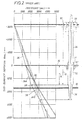
Fig. 2 , conventional drilling technology using ariser 34 for drilling a subsea borehole is shown. Thedepth 14 to the top of the abnormal pore pressure environment, in this example, is 1500 feet when referenced to themudline 16 of the sea floor SF or adepth 18 of 4,780 feet when referenced to thekelly bushing 20 on the rig floor of thefloating vessel 22. - An abnormal pore pressure environment is an environment where the hydrostatic pressure of sea water will not control the pore pressure. In other words, an abnormal pore pressure environment is an environment where the hydrostatic pressure generated by a column of sea water is less than the pore fluid pressure of the geological formations surrounding the borehole.
- Therefore, the example well in
Fig. 2 can be safely drilled using sea water as the drilling fluid to a depth of 1500 feet, since thepore pressure 24A in the normal pore pressure environment is equal to the hydrostatic pressure of sea water (8.6 ppg) 26 down to this depth. In other words, the increase in the pore pressure gradient at 1500 feet, as seen by the slope change at 28, indicates that the maximum casing depth for conductor or the first casing is 1500 feet. Since the maximum setting depth of the first casing in the example well is a function of thepore pressure 24A and thefracture pressure 30, the drilling and casing can be accomplished without a riser using sea water. Therefore, as discussed above, the first portion (the "normal pressure" portion of the well) of the borehole above 1500 feet in this example well is drilled and cased without a riser. - Since the first portion of the borehole (above 1500 feet) can be drilled without a riser, the diameter of the
first casing 32 is not limited by theriser 34. However, in this example, the riser 34 (and a drilling fluid having additives) is required when using conventional drilling technology to drill depths greater than 1500 feet. Becausecasing 36 must pass through the conventional 18 inch diameter clearance blowout preventer (BOP)stack inch diameter riser 34, selecting a casing size for thefirst casing 32 which is much larger than theriser 34 andBOP stack 37 clearance is of no benefit. Presently, most floating vessels do not handle risers bigger than 19 inches in diameter. As a result, risers greater than 19 inches in diameter are not used. The cost of upgrading the floating vessel for a larger riser diameter is quite high due to the increase load which would be imposed on the vessel when handling the larger, heavier risers. As a result, thesecond casing 36 run into the conventional-drilled well, such as shown inFig. 2 , is limited by the riser 34 (18 inches in diameter) and must have clearance to pass through a 18 inch diameter. Therefore, in the example ofFig. 2 , selecting the size of thefirst casing 32 to be as close as possible to theriser 34 diameter is the most cost effective. Thus, the selected size of first and second casings run into the conventionally-drilled example well are 20 inches and 16 inches, respectively. In order to maintain the borehole fluid pressure for the second casing between the pore pressure 24B and thefracture pressure 30, the borehole for the second casing can be drilled to approximately 2,560 feet, as shown graphically inFig. 2 . The line 38 (indicating use of a fluid with additives-a 10.1 ppg mud) is maintained between the pore pressure line 24B and thefracture line 30 with a 200 psi safety margin while being drilled through theshallow aquifer 10 to 2,560 feet. -
U.S. Patent No. 4,813,495 proposes an alternative to the conventional drilling method and apparatus ofFig. 2 by using a subsea rotating control head in conjunction with a subsea pump that returns the drilling fluid to a drilling vessel. Since the drilling fluid is returned to the drilling vessel, a fluid with additives may economically be used for continuous drilling operations. ('495 patent, col. 6, ln. 15 to col. 7, In. 24) Therefore, the '495 patent moves the base line for measuring pressure gradient from the sea surface to the mudline of the sea floor ('495 patent, col. 1, Ins. 31-34). This change in positioning of the base line removes the weight of the drilling fluid or hydrostatic pressure contained in a conventional riser from the formation. This objective is achieved by taking the fluid or mud returns at the mudline and pumping them to the surface rather than requiring the mud returns to be forced upward through the riser by the downward pressure of the mud column ('495 patent, col. 1, lns. 35-40). Therefore, the '495 patent, while acknowledging the economic and environmental concerns of dumping, proposes the use of drilling fluids with additives that are only dumped to the sea floor in an emergency. ('495 patent, col. 3, Ins. 30-35) - An apparatus for controlling a subsea borehole fluid pressure is proposed for use with a conductor casing positioned below the mudline and within a normal pore pressure environment. The apparatus includes a pump for moving a fluid through a tubular into a borehole. The fluid, before being pumped, exerts a pressure less than the pore pressure of an abnormal pore pressure environment. The fluid in the borehole is then pressurized by the pump to at least a borehole pressure equal to or greater than the pore pressure. A pressure housing assembly includes a rotating control head having a sealed bearing assembly comprising an inner member and outer member. The inner member is rotatable relative to the outer member and has a passage through which the tubular may extend. The tubular is sealed with the rotatable inner barrel. The pressure housing assembly further includes a pressure control device to control pressure in the pressure housing assembly and the pressure housing assembly is sealably positioned with the conductor casing. The pressure housing assembly allows for the drilling of a borehole below the conductor casing into an abnormal pore pressure environment while maintaining sufficient fluid pressurization to maintain a borehole pressure equal to or greater than the pore pressure. The upper limit for borehole fluid pressurization is controlled by formation fracture resistance, and the borehole pressure must be maintained below this pressure. The pressure housing assembly allows for the drilling of a borehole below the conductor casing into an abnormal pore pressure environment while maintaining the borehole fluid pressurization below the fracture pressure of the borehole in the abnormal pore pressure environment. Advantageously, a method is provided for drilling a borehole into the subsea abnormal pore pressure environment.
- A better understanding of the present invention can be obtained when the following detailed description of the preferred embodiment is considered in conjunction with the following drawings, in which:
-
Fig. 1 is an elevational view of a drilling method where an abnormal pore pressure environment has resulted in an undesired flow path from the well to the sea floor; -
Fig. 2 is an elevational graphic view of a floating vessel using a conventional riser for drilling through an abnormal pore pressure environment; -
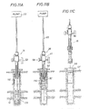
Fig. 3 is a perspective view of the pressure housing assembly of the present invention including a housing, a bearing assembly, a seal and a pressure control device; -
Fig. 4 is an exploded view of the present invention shown inFig. 3 ; -
Fig. 5 is an exploded elevational view of the pressure housing assembly shown inFig. 4 , further including a fastening and sealing member that is actuated by a running collar connected to a drill string; -
Fig. 6 is a section view of the pressure housing assembly as shown inFig. 3 ; -
Fig. 7 is an elevational graphic view of the present invention using the pressure housing assembly as shown inFigs. 3-6 ; -
Fig. 8 is an elevational graphic view of the effects of losing fluid with additives at the casing shoe while performing the method of the present invention; -
Fig. 9 is an elevational view of the preferred embodiment of the invention for drilling in a subsea borehole; -
Fig. 10 is an elevational view of the preferred embodiment of the invention used to drill into an abnormal pore pressure environment including an abnormally pressured aquifer; -
Fig. 11 is an elevational view of the steps for removal of preferred embodiment of the invention after drilling into the abnormal pore pressure environment including disengaging the fastening and sealing member and removing the pressure housing assembly from the borehole using the running collar on a drill string; -
Fig. 12A is a graph of a casing design if conventional drilling techniques and riser sizes are used for drilling the example case discussed in the background of the invention; -
Fig. 12B is a graph of the extended benefits of the present invention providing a second casing of larger diameter than the conventional drilling method, as shown inFigs. 2 and12A ; and -
Fig. 13 , is an alternative embodiment of the present invention sealingly positioned on a conventional blowout preventer stack attached to a wellhead extending from a conductor casing in a subsea borehole. - The preferred embodiment of the
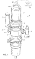
pressure housing assembly 15 is illustrated inFigs. 3-12 and an alternative embodiment of thepressure housing assembly 15A is illustrated inFig. 13 . The preferred embodiment of the a pressure housing assembly, generally indicated at 15, includes a rotating blowout preventer or rotating control head, generally indicated at 38, and best shown inFigs. 3 ,4 ,5 and6 . Thecontrol head 38 is similar to the rotating blowout preventer disclosed inU.S. Patent No. 5,662,181 , that is assigned to the assignee of the present invention and incorporated herein by reference for all purposes. Contemplated modifications to the '181 rotating blowout preventer include deletion of the kelly driver and the corresponding drive lugs located on thetop rubber drive 40. Additionally, the clamp cylinder and drilling mud fill line could be deleted. However, thehousing 44 preferably includes threereturn outlets return outlets 46 and 50 are preferably connected to redundant choking or pressure control devices, such aspressure control device 52, shown inFigs. 3 and6 and as discussed below in detail. Thereturn outlet 48 is used for an orifice valve, as discussed below in detail. Because thepressure housing assembly 15 is preferably self contained, a self containedlubrication unit 54 is preferably provided for communication with the lubricant inlet fitting, as disclosed in the '181 patent, to provide lubrication to the sealed bearing assembly, as discussed below in detail. The self containedpressure housing assembly 15, including thecontrol head 38 andpressure control device 52, will not require long hydraulic hose bundles or electrical wires run from a floating vessel to the sea floor. It is also contemplated that the cooling water inlet and outlet fittings of the rotating blowout preventer of the '181 patent would not be required, in view of the cool subsea environment in which the present invention will be used. - Turning now to
Figs. 3 to 6 , thepressure housing assembly 15control head 38 would include atop rubber pot 56 containing atop stripper rubber 58, as best shown inFigs. 4 and6 . Thetop rubber pot 56 is mounted to the bearing assembly, generally indicated at 60, having an inner member orbarrel 62 and anouter barrel 64, as best shown inFig. 6 . Theinner barrel 62 rotates with thetop rubber pot 56 and itstop stripper rubber 58 that seals with thedrill string 66. Abottom stripper rubber 78 is also preferably attached to theinner barrel 62 to engage and rotate with thedrill string 66. As can best be seen inFigs. 5 and6 , theinner barrel 62 andouter barrel 64 are received in thefirst opening 44A of thehousing 44 of thepressure housing assembly 15 and the pressure control device, generally indicated at 52, is connected to a second housing opening 44B of thehousing 44 of thepressure housing assembly 15. Theouter barrel 64, clamped and locked to thehousing 44 byclamp 42, remains stationary with thehousing 44 of thepressure housing assembly 15. - As disclosed in
U.S. Patent No. 5,662,181 , and best shown inFig. 6 ,radial bearings thrust bearings 70A and 70B,plates lubrication unit 54 provides subsea lubrication of the bearing assembly. As best shown inFig. 6 , thelubrication unit 54 would be pressurized by a spring-loadedpiston 54A inside theunit 54 and pushed through tubing and flow channels to thebearings unit 54 to insure proper bearing lubrication of theassembly 15 until it is tripped out. Thelubrication unit 54 would preferably be mounted on theupper housing 44. The chamber 54B on the spring side of thepiston 54A, which contains the lubricant forced into the bearing assembly, could be in communication with thehousing 44 of the pressure assembly by means of atube 54C. This would assure that the force driving thepiston 54A is controlled by the spring 54D, regardless of the water depth or internal well pressure. Alternately, the spring side of thepiston 54A could be vented to the sea. - Turning now to
Fig. 5 , an exploded view of the preferred embodiment of thepressure housing assembly 15 is shown having a fastening and sealing assembly orpacker assembly 90. In particular, the fastening and sealing assembly includes apacker assembly 90 positioned above the third housing opening 44C of thehousing 44 to sealingly position thepressure housing assembly 15 in thecasing 110. In particular, thepacker assembly 90 will be sized so as to be able to seal against the internal diameter of thecasing 110 in the subsea borehole, as discussed below. Thepacker assembly 90 will provide mechanical attachment of thepressure housing assembly 15 to the casing by means of radial expandable slips 90A. Thepacker assembly 90 will also provide a pressure seal by means of an outwardlyexpandable sealing element 90B. Thepacker assembly 90 will preferably have setting and release mechanisms which can be engaged and manipulated by runningcollar 92 affixed to thedrill string 66. The runningcollar 92 is preferably fixed to thedrill string 66 above thebit 94 andmud motor 96. The runningcollar 92 will transmit mechanical torque and axial forces to the setting mechanism in thepacker assembly 90 during the setting process. After releasing thecollar 92 from thepacker assembly 90, the runningcollar 92 can continue down the well as part of the drilling assembly. When thebit 94 is tripped out, the runningcollar 92 will again be raised to thepacker assembly 90 to unseat the packer slips 90A and sealingelement 90B. - Turning now back to
Fig. 6 , the pressure control device orregulator 52 will be used as a primary pressure control device for the fluid in theannulus 100 of the well, as shown inFig. 7 . In the preferredpressure housing assembly 15, theregulator 52 opening pressure will be set on the floatingvessel 22. After thepressure housing assembly 15 has been run and sealingly positioned, thepump 53 can be used to pressure up the well to thepressure regulator 52 pre-set opening pressure. Once the set pressure is achieved, theregulator 52 will open. After theregulator 52 opens, sea water will circulate down thedrill string 66 outbit 94, up theannulus 100 and through theregulator 52, and preferably discharged at the sea floor SF. When the pump rate is increased theregulator 52 will open up in order to maintain pressure in theannulus 100 of the well at the regulator's pre-set pressure. When the pump rate is decreased theregulator 52 will begin closing in order to maintain pressure in theannulus 100 of the well at theregulator 52 set pressure. A back up or second pressure regulator (not shown) with a slightly higher pre-set pressure is preferably attached to a third return outlet 50 ofhousing 44 to act as a back up to theprimary pressure regulator 52. If theprimary pressure regulator 52 failed to operate properly and the pressure in theannulus 100 exceeded the secondary regulator set point, the secondary regulator would begin to operate. - Turning to
Figs. 6 and8 , anorifice valve 98 is used for circulating a limited amount of fluid with additives (heavy mud) 116 into the borehole in preparation for tripping out thepressure housing assembly 15. Thevalve 98 would preferably have a removable orifice mounted in the valves outlet. The valve will remain closed until thepressure housing assembly 15 is ready to be tripped out of the hole. Before starting out of the hole with thebit 94, kill fluid or heavy mud would be pumped into theannulus 100, as best shown inFig. 7 . As the mud interface begins moving up theannulus 100, theorifice valve 98 would be opened. The size of the orifice and pump rate would be pre-selected to provide enough back pressure on theannulus 100 to prevent the well from flowing. As the kill mud moved up theannulus 100, less pressure would be required to maintain a desired borehole pressure, so the pump rate would be gradually reduced. Once the kill mud reached thepressure housing assembly 15, thepump 53 would be shut off and the orifice valve opened. With the well static, thedrill string 66 could be pulled, thepacker assembly 90 unseated and the drilling assembly including thedrill string 66 along with thepressure housing assembly 15 pulled, as discussed below in detail. A remotely controlled vehicle at the sea floor will preferably actuate thevalve 98. Alternatively, theorifice valve 98 could be actuated using a pump rate signaling technique or drill pipe manipulation. - It is contemplated that additional refinements can be made to the present invention such as use of sensors for 1.) measuring the annular pressure at the
control head 38, 2.) fluid ejection rate, and 3.) gas detection. Also remote operation of both theannular pressure regulator 52 andorifice valve 98 is contemplated. Also, remotely operated vehicles, as discussed above, and a remote intelligent control system could be used. - In particular, a sensor could be used for real-time mudline annular pressure monitoring so that any failures in the system can be detected while drilling. Monitoring the mudline annular pressure during any shut in periods would help with the detection of abnormal pore pressure environments and casing shoe failures, as discussed below. Preferably, an existing measurement-while-drilling (MWD) tool outfitted with annular pressure sensors could be used. However, when using a MWD tool, pressures could only be transmitted when the well is being circulated and the data would be received at relatively slow transmission rates. Additionally, a fluid ejection rate sensor located on the
fluid discharge outlets vessel 22, in the present invention, the flow rate out, returned from the well, cannot be compared to the pump rate into the well. Real-time flow return monitoring would be useful for detecting casing shoe failures and loss circulation zones. Also, sensors for monitoring the presence or concentration of gas in the discharge flow stream would also be useful for early kick detection and will provide information about the subsurface environment being drilled. - Preferably, the
pressure regulator 52 will be set while the device was on the rig and run into the well. If the pore pressure and fracture pressures are accurately predicted, this form of pressure regulation should be sufficient. If, however, theshallow aquifer 10 in the abnormal pore pressure environment contained higher pore pressures than expected, thedrill string 66 with thepressure housing assembly 15 would have to be tripped to the sea surface so that theregulator 52 set pressure could be adjusted. If the annular regulator set pressure could be adjusted remotely during drilling, then there would not be a need for tripping thedrill string 66. A remotely adjustable regulator would also eliminate need for theorifice valve 98 because the regulator set pressure could be reduced as kill mud was circulated up theannulus 100 prior to tripping thedrill string 66. - If a remotely controlled pressure regulator, as discussed immediately above, is not used for annular pressure control, the
orifice valve 98 would be the only component on thepressure housing assembly 15 which requires remote operation. The form of remote control could take any of several forms. For example, acoustic pulses from the floatingvessel 22 could be transmitted through the sea water to a simple control system on thepressure housing assembly 15, once the control system received and confirmed the signal to open theorifice valve 98, it could actuate the valve by hydraulic, electrical, or mechanical means. The circulatingpump 53 on the floating vessel could also be cycled in a special way to signal a mechanical or electrical device which would in turn actuate thevalve 98. A third option would be to cycle thedrill string 66 rotation speeds as a means of signaling theorifice valve 98 actuation. A conventional remotely operated vehicle could be used to both actuate theorifice valve 98 and inspect thewellhead 126 andpressure housing assembly 15 before tripping thedrill string 66. The remotely operated vehicle could also be used to check for flow and make sure the well is dead after the circulatingkill fluid 116 is moved into theannulus 100. The remotely operable vehicle could also be used to monitor pressure and actuate theorifice valve 98 when kill mud is being circulated, thereby eliminating the need for any special provisions for remotely actuating theorifice valve 98. - It is contemplated that the first prototype of the present invention will have a remotely operated vehicle docked to the
pressure housing assembly 15 after it has been set and run. Annular pressure and flow rate could be continuously transmitted to the surface through the remotely operated vehicle umbilical and the remotely operated vehicle could be used to adjust theannular pressure regulator 52 set point. Also, it is contemplated that later models may use an on board computer which could take care of simple control functions and transmit data to the surface via acoustic, radio , laser, mud pulse, fiber-optic or an electrical style telemetry system. Instructions would also be sent to the on-board computer by one of the same forms of data transmission. A reliable system of this type could provide more flexibility and could prove cost effective by eliminating the need for any remotely operated vehicle intervention. - Turning now to
Fig. 13 , a subseapressure housing assembly 15A, as discussed above, is mounted on top of an annular BOP preventer ABOP of a subsea blowout preventer stack BOPS connected to awellhead 126. In this alternative embodiment, the casingtype packer assembly 90 would not be used because it would interfere with the stack BOPS. Thepressure housing assembly 15A would be mounted on top of the annular preventer ABOP (before running the BOP stack) using a fastening and sealing assembly 90'. Because the BOP stacks require a hose bundle to remotely actuate BOP components, the fastening and sealing assembly 92'90' could be a hydraulically actuated clamp, such as a Cameron HC Collet connector. - Turning now to
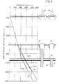
Figs. 7-11 , the method for operation of the present invention is illustrated. In particular,Fig. 7 illustrates the possible casing size and setting depth selections for the first two casings run into an example well drilled to control borehole pressures using the method of the present invention. The properly installedpressure housing assembly 15, as discussed above, would maintain a back pressure on the fluid in theannulus 100 while drilling with thedrill string 66. Thepressure housing assembly 15 provides back pressure in addition to the hydrostatic pressure acting on the fluid in theannulus 100. This total pressure would allow the well to be drilled safely to a depth greater than 1500 feet while only using sea water as the drilling fluid. Since sea water is being used as the drilling fluid, a riser is not required since the drilling fluid can be discharged at the sea floor SF. Thus, while the present invention does not allow drilling to the final depth of the well without a riser, it does allow more of the well to be drilled without the riser. This riserless technology allows thesecond casing 108 to be larger than the inside diameter of the conventional riser, such as discussed above and shown inFig. 2 . If thepressure housing assembly 15 maintains a back pressure of 400psi on the example well, as illustrated inFig. 7 , sea water having a density of 8.6 ppg could be used for the drilling fluid until adepth 101 of about 2,350 feet, that is below theshallow aquifer 10 and into the abnormal pore pressure environment. Below a depth of 2,3 50 feet-RML, the pore pressure in the sediments exceeds the total borehole pressure (fluid pressurization plus fluid hydrostatic pressure) which is generated by pressurizing the sea water an additional 400 psi. This depth is indicated at theintersection 106 of thepore pressure line 102 and the 400psi line 104. Therefore, drilling below 2,350 feet in this example would require a heavier drilling fluid, that is a fluid with additives in order to prevent an uncontrolled flow from an abnormally pressured formation. As a consequence, a riser and a third casing would be required to drill below 2,350 feet, in this example. Since, neither the first or the second casing was required to pass through the conventional riser, importantly, as a result, a twenty-inch diametersecond casing 108 may be set as deep as 2,350 feet. This is 850 feet deeper than with conventional drilling techniques without a riser, such as shown inFig. 2 . However, as seen inFigs. 12A and12B , if the example wells ofFigs. 2 and7 are continued by selecting and setting successively smaller casings until the maximum total depth of the well was reached, significant increases in the possible maximum total depth of the well drilled is realized.Fig. 12A andFig 12B depict the pore pressure and overburden pressure for the example case developed inFigures 2 ,7 , and8 .Fig. 12A shows the casing program that would result if 16" casing were set at 2560 feet-RML with the conventional methods depicted inFig. 2 . The maximum total depth of the well would be 9200 feet-RML if 9-5/8" diameter casing were to be used as production casing and 0.5 ppg safety margins were observed throughout the drilling of the well.Fig. 12B shows the casing program that would result if 20" casing were set at 2350 feet-RML using the riserless method depicted inFig. 7 . The maximum total depth for 9-5/8" production casing would be 14,700 feet-RML if 0.5 ppg safety margins were used. By setting the 20" casing below the shallow water aquifers the well can be drilled a total of 5,500 feet deeper by using the riserless method described here. - In the example well of
Fig. 7 , using the present invention, a 200psi safety margin was used similar to the safety margin of the example well ofFig. 2 . Though, if a lower safety margin was used, casing 108 could be set even deeper than 2,350 feet. - Turning now to
Fig. 8 , becausekill mud 116 will be circulated into the well after drilling the borehole, casing shoe safety margins can be considerably lower than conventional casing shoe pressure safety margins.Fig. 8 shows the well borepressure profile 120A if 18 ppg kill fluid or mud is circulated to within 450 feet of the sea floor SF. Even if all the mud between the sea floor SF and thecasing shoe 112 were lost inflow path 112A, the total pressure created by the column of sea water 114 (8.6 ppg) and the remaining mud 116 (18 ppg) is sufficient to maintain control of the well. This total pressure should control theshallow water aquifer 10 in the abnormal pore pressure environment thereby, as graphically shown, controlling the pore pressure either with an essentially full column of mud (as depicted withline 120A) or if the mud is lost down to thecasing shoe 120B,(as depicted withline 120B). Both lines fall between thepore pressure 122 andfracture pressure 124 lines of abnormal pressure environment, thereby indicating the well is controlled in both conditions. - Turning to
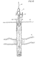
Fig. 9 , the preferredpressure housing assembly 15 is shown positioned and sealed with theconductor casing 110. Awellhead 126 is attached to theconductor casing 110 above the sea floor SF. Thepressure housing assembly 15 controls the back pressure on the borehole 128 using apump 53 to pressurize the fluid in addition to the hydrostatic pressure created by the weight of a column of drilling fluid without additives, such as sea water. The preferredpressure housing assembly 15 includes a subsea lubricatedrotating control head 38 and an adjustableconstant pressure regulator 52 sealably positioned in thecasing 110 by thepacker assembly 90, as discussed above. Thepressure housing assembly 15 maintains the borehole pressure to above the pore pressure of the abnormal pore pressure environment without using drilling fluid having a density above that of sea water. Therefore, after a single pass of the sea water through theannulus 110, it can be discharged from thepressure housing assembly 15 adjacent the sea floor SF. Above a critical depth of theborehole 128 beyond which the back pressure required to control flow in the abnormal pore pressure environment exceeds the current limitations of the equipment, fluid with additives or mud, and the resulting riser, would be necessary. Only when thedrill string 66 is tripped out of the borehole 128 after drilling would a limited amount of fluid with additives be needed. - As shown in
Fig. 9 , the pressuredhousing assembly 15 would ride on top of a runningcollar 92 affixed to thedrill string 66 above thedrill bit 94 andmud motor 96. Thepressure housing assembly 15, as shown inFig. 9 , will preferably be totally self-contained in that it would not need to be connected by lines to the floatingvessel 22 and also would not require any special tools and flanges to be attached to thecasing 110 before thepressure housing assembly 15 could be used. As discussed above, the fastening means 90A and sealing means 90B of thepacker assembly 90 provide a pressure seal and mechanical attachment of thepressure housing assembly 15 to the inside of thecasing 110 below thewellhead 126. Thepacker assembly 90 would be positioned below thewellhead 126 with therotating control head 38 near the mudline of the sea floor SF. By rotating thedrill string 66 from the floatingvessel 22, which in turn would rotate the runningcollar 92, thepacker assembly 90 would be set. Once thepacker assembly 90 was set, the runningcollar 92 would disengage from thepacker assembly 90 allowing thedrill string 66 is continue into theborehole 128. Thetop stripper rubber 58 andbottom stripper rubber 78 would engage and seal around thedrill string 66 isolating and containing annular fluids in the well bore WB. As best shown inFig. 10 , return flow of fluid from the well is routed through thepressure control device 52 in communication with thesecond housing opening 44B. Thisconstant pressure regulator 52 or other choking device attached to the discharge manifold ofhousing 44 would regulate the well pressure by maintaining a back pressure on any abnormal pore pressure environment, including abnormally pressuredaquifers 10. This back pressure would control any potential flow from theaquifer 10, even though the drilling fluid used is sea water. - Turning now to
Fig. 11 , as discussed above, when tripping out of the hole, a drilling fluid with additives ormud 116 would be pumped into the hole to maintain pressure on the borehole128. Themud 116 would be circulated into the hole by means of a third remotely actuatedvalve 98 attached to the discharge manifold of thehousing 44. Thisorifice valve 98 would have a sized orifice mounted in its outlet. Sea water would first be circulated at a predetermined rate and the orifice valve opened. Once the orifice valve was opened, killmud 116 would be pumped into the well. As thekill mud 116 moved up theannulus 110 more hydrostatic pressure would be placed on thehole 128. To offset this pressure increase, thepump 53 would be slowed down to reduce the back pressure. Once the kill mud reached the mudline of the sea floor SF, the back pressure would be reduced to zero. The runningcollar 92 would engage thepacker assembly 90 at its bottom to release it. The whole self containedpressure housing assembly 15 would then be tripped up to the floatingvessel 22 supported by the runningcollar 92. As discussed above, themud 116 in the hole could prevent any flow from being produced. Although, thismud 116 would not be recovered when thecasing 108 is run into the hole and the hole cemented, the waste would be limited to the volume of the well bore as best seen inFigs 8 and11 . - After completing the casing of shallow, large diameter portion of the well, a conventional riser or other method could be used to drill the smaller diameter and deeper sections of the well. While the method and apparatus of the present invention is to be used where the drilling fluid can be economically discarded after a single pass, it offers a simple and effective aid in eliminating the physical and economic constraints associated with the initial phases of drilling a well in deep water.
- It can now be understood that the maximum depth in which casing larger than the BOP stack or riser can be set controls the maximum total depth of the well and the maximum diameter of the final production casing. The advantages of larger production casings are higher production rate potentials and greater well bore utility for future drilling operations, such as side-tracking. As can now be seen, the subsea
pressure housing assembly 15, when applied to riserless drilling, increases the maximum total depth to which a well can be drilled in a given water depth by increasing the depth that can be drilled before a riser becomes necessary. Substantial cost savings can also be realized by using smaller floating vessels (without riser capabilities) to drill the shallow, large-diameter hole sections to a depth below the high risk shallow water aquifers. Casing could then be set to seal off the water flows, and the location could then be temporarily abandoned until a larger floating vessel was available to finish drilling the well to the target objective. The smaller floating vessel needed for the present invention would be cheaper to operate than the current large floating vessels. Also, if wells were lost because of water flows, the financial impact would be much less than if the shallow high risk section of the wells were drilled with a larger floating vessel. This cost effective site preparation using the subseapressure housing assembly - The foregoing disclosure and description of the invention are illustrative and explanatory thereof, and various changes in the details of the illustrated apparatus and construction and method of operation may be made without departing from the spirit of the invention. The invention may also be defined by means of the following numbered clauses:
- 1. Method for controlling a subsea borehole fluid pressure, comprising the steps of:
- positioning a portion of a casing below the subsea mudline and within a normal pore pressure environment,
- moving a fluid in the casing that exerts a pressure less than the pore pressure of an abnormal pore pressure environment,
- pressurizing the fluid to at least a borehole pressure equal to or greater than the pore pressure of the abnormal pore pressure environment, and
- drilling a borehole below the casing into an abnormal pore pressure environment while maintaining the borehole pressure equal to or greater than the pore pressure of the abnormal pore pressure environment.
- 2. Apparatus for controlling a subsea borehole fluid pressure adapted for use with a casing positioned below the mudline and within a normal pore pressure environment, comprising:
- a pump for moving a fluid in the casing, said fluid exerting a pressure less than the pore pressure of an abnormal pore pressure environment, said fluid being pressurized by the pump to at least a borehole pressure equal to or greater than the pore pressure of an abnormal pore pressure environment, and
- means for drilling a borehole below the casing into abnormal pore pressure environment while maintaining the borehole pressure equal to or greater than the pore pressure of the abnormal pore pressure environment.
- 3. Apparatus of 2 wherein said means for drilling includes,
a housing having a first housing opening, a second housing opening and third housing opening;
a bearing assembly having an inner member and an outer member and disposed with said first housing opening, said inner member rotatable relative to said outer member and having a passage through which a tubular may extend;
a seal to sealably engage the tubular with the inner barrel;
a pressure control device in communication with said second housing opening to control pressure in said housing; and
said third housing opening sealingly positioned with the casing. - 4. Apparatus adapted for use with a casing for controlling a subsea borehole fluid pressure while drilling in an abnormal pore pressure environment, comprising
a housing having a first housing opening, a second housing opening and third housing opening;
a tubular extending through said first opening;
a seal to sealably engage the tubular;
a pressure control device in communication with said second housing opening to control pressure in said housing;
said third housing opening sealingly positioned with the casing; and
a pump for pumping fluid through the tubular and pressurizing the fluid in the borehole whereby said fluid, exerting a pressure less than the pore pressure of an abnormal pore pressure environment before being pumped, being pressurized by said pump and said pressure control device to at least a borehole pressure equal to or greater than the pore pressure of an abnormal pore pressure environment while drilling the borehole through an abnormal pore pressure environment - 5. Apparatus of 4 further comprising a fastening and sealing assembly to sealingly position said third housing opening with the casing.
- 6. Method for controlling a subsea borehole fluid pressure between a pore pressure and a fracture pressure of a subsea borehole, comprising the steps of:
- casing a portion of the subsea borehole;
- sealingly positioning a housing with the casing;
- sealingly positioning a tubular with the housing so that the tubular extends through the housing and into the borehole;
- moving a fluid, that exerts a pressure less than the pore pressure, from the tubular into the casing; and
- controlling the pressure of the fluid in the borehole between a borehole pressure equal to or greater than the pore pressure of the abnormal pore pressure environment, and a borehole pressure equal to or less than the fracture pressure of the abnormal pore pressure environment.
- 7. Apparatus adapted for use with a casing and a rotatable tubular for controlling subsea borehole fluid pressure while drilling in an abnormal pore pressure environment, comprising:
- a housing having a first housing opening, a second housing opening and third housing opening;
- a bearing assembly having an inner member and an outer member and disposed with said first housing opening, said inner member rotatable relative to said outer member and having a passage through which the tubular may extend;
- a seal to sealably engage the tubular with the inner barrel;
- a pressure control device in communication with said second housing opening to control pressure in said housing;
- said third housing opening sealingly positioned with the casing; and
- a pump for pumping a fluid, that exerts a pressure less than the pore pressure of the abnormal pore pressure environment, through the tubular and pressurizing the fluid whereby said bearing assembly, said seal, and said pressure control device provide a fluid in a subsea borehole that maintains a borehole pressure equal to or greater than the pore pressure of the abnormal pore pressure environment
- 8. Apparatus of 7 further comprising a fastening and sealing assembly to sealingly position said third housing opening with the casing.
- 9. Method for controlling a subsea borehole fluid pressure, comprising the steps of:
- casing a portion of the subsea borehole;
- sealingly positioning a housing with the casing;
- sealingly positioning a tubular with the housing so that the tubular extends through the housing and into the borehole;
- rotating the tubular relative to the housing while maintaining the seal between the tubular and the housing;
- moving fluid, that exerts a pressure less than the pore pressure of an abnormal pore pressure environment, from the tubular into the borehole;
- controlling the pressure of the fluid in the borehole as the borehole extends into an abnormal pore pressure environment; and
- moving fluid from said housing into the sea.
- 10. Apparatus adapted for use with a casing and a rotatable tubular for controlling a subsea borehole fluid pressure, comprising
a housing having a first housing opening, a second housing opening and third housing opening;
a sealed bearing assembly having an inner barrel and an outer barrel and disposed with said first housing opening, said inner barrel rotatable relative to said outer barrel and having a passage through which the tubular may extend;
a seal moving with said inner barrel to sealably engage the tubular;
a pressure control device in communication with said second housing opening to control pressure in said housing;
a fastening and sealing assembly disposed adjacent to said third housing opening to sealably engage said housing with the casing; and
a pump for pumping fluid, exerting a pressure less than the pore pressure of an abnormal pore pressure environment, through the tubular and pressurizing the fluid in the borehole whereby said bearing assembly, said seal, said pressure control device and said fastening and sealing assembly provide a subsea borehole having a pressure equal to or greater than the pore pressure of the abnormal pore pressure environment while rotating the tubular in the subsea borehole. - 11. Apparatus of 10 further comprising
a subsea lubrication unit for injecting lubrication into said sealed bearing assembly. - 12. Method for controlling a subsea borehole fluid pressure, comprising the steps of:
- casing a portion of the subsea borehole;
- sealingly positioning a housing with the casing;
- sealingly positioning a tubular with the housing so that the tubular extends through the housing and into the borehole;
- rotating the tubular relative to the housing while maintaining the seal between the tubular and the housing;
- moving a fluid from the tubular into the borehole; and
- pressuring the fluid in the borehole from a pressure less than the pore pressure to a pressure greater than the pore pressure.
- 13. Method of 12 wherein said housing having a first housing opening, a second housing opening and third housing opening, and further comprising;
a bearing assembly having an inner member and an outer member and disposed with said first housing opening, said inner member rotatable relative to said outer member and having a passage through which the tubular may extend;
a seal to sealably engage the tubular with the inner barrel; and
a pressure control device in communication with said second housing opening to control pressure in the housing. - 14. Method of 13 further comprising
said third housing opening sealingly positioned with the casing; and
a pump for pumping fluid through the tubular and pressurizing the fluid in the borehole whereby said fluid, exerting a pressure less than the pore pressure before being pumped, being pressurized by said pump and said pressure control device to at least a borehole pressure equal to or greater than the pore pressure while drilling the borehole through an abnormal pore pressure environment. - 15. Method of 12 further comprising the step of pumping kill fluid at a variable rate to maintain a desired borehole pressure.
- 16. Method of 13 further comprising the step of pumping kill fluid at a variable rate to maintain a desired borehole pressure.
- 17. Method of 16 further comprising said housing having a fourth housing opening; and
an orifice in communication with said fourth housing opening, said orifice having a predetermined size to provide sufficient back pressure in the borehole to control the subsea borehole fluid pressure. - 18. Method of 17 further comprising the steps of
closing the orifice until the housing is ready to be removed from the borehole.
Claims (8)
- A method for controlling a subsea borehole fluid pressure, comprising the steps of:supporting a portion of a subsea borehole with a supporting structure;sealingly positioning a housing with the supporting structure;sealingly positioning a string with the housing so that the string extends through the housing and into the borehole,rotating the string relative to the housing while maintaining the seal between the string and the housing;moving a fluid, that exerts a pressure less than a pore pressure of an abnormal pore pressure environment before being pressurized, into the borehole; andincreasing the pressure of said fluid in the borehole while continuing the step of rotating the string in the abnormal pore pressure environment.
- The method of claim 1, wherein said housing has a first housing opening, a second housing opening and a third housing opening, and further comprising:a bearing assembly having an inner member and an outer member and disposed with said first housing opening, said inner member rotatable relative to said outer member and having a passage through which the string may extend;a seal to sealably engage the string with the inner member; anda pressure control device in communication with said second housing opening for controlling pressure in the housing.
- The method of claim 2, further comprising:sealingly positioning said third housing opening with the supporting structure; andproviding a pump for pumping fluid and for pressurizing the fluid in the borehole whereby said fluid is pressurized by said pump and maintained by said pressure control device while drilling the borehole through the abnormal pore pressure environment.
- The method of any preceding claim, further comprising the step of pumping a kill fluid at a variable rate to maintain a desired borehole pressure.
- Apparatus adapted for use with a tubular for controlling a subsea borehole fluid pressure while rotating the tubular in an abnormal pore pressure environment, the tubular constituting a portion of a string of tubulars, the apparatus comprising:a supporting structure for supporting a portion of a subsea borehole;a housing sealingly positioned with the supporting structure and arranged to receive the string so that the string extends through the housing and into the borehole;a seal arranged to seal the string with the housing when the string is positioned with the housing;means for rotating the string relative to the housing while maintaining the seal between the string and the housing;means for moving a fluid, that exerts a pressure less than a pore pressure of the abnormal pore pressure environment before being pressurized, into the borehole; andmeans for increasing the pressure of said fluid in the borehole during rotation of the string in the abnormal pore pressure environment.
- The apparatus of claim 5, wherein said housing has a first housing opening, a second housing opening and a third housing opening, and further comprising:a bearing assembly having an inner member and an outer member and disposed with said first housing opening, said inner member rotatable relative to said outer member and having a passage through which the string may extend;a seal to sealably engage the string with the inner member; anda pressure control device in communication with said second housing opening for controlling pressure in the housing.
- The apparatus of claim 6, wherein said third housing opening is sealingly positioned with the supporting structure, the apparatus further comprising a pump for pumping fluid and for pressurizing the fluid in the borehole whereby said pump is arranged to pressurize said fluid and said pressure control device is arranged to maintain said pressure while the borehole is being drilled through the abnormal pore pressure environment.
- The apparatus of any one of claims 5 to 7, the apparatus further being arranged to pump a kill fluid at a variable rate to maintain a desired borehole pressure.
Applications Claiming Priority (2)
| Application Number | Priority Date | Filing Date | Title |
|---|---|---|---|
| US09/033,190 US6138774A (en) | 1998-03-02 | 1998-03-02 | Method and apparatus for drilling a borehole into a subsea abnormal pore pressure environment |
| EP99908371A EP1060320A4 (en) | 1998-03-02 | 1999-02-24 | Method and apparatus for drilling a borehole into a subsea abnormal pore pressure environment |
Related Parent Applications (1)
| Application Number | Title | Priority Date | Filing Date |
|---|---|---|---|
| EP99908371.0 Division | 1999-02-24 |
Publications (2)
| Publication Number | Publication Date |
|---|---|
| EP2261456A2 true EP2261456A2 (en) | 2010-12-15 |
| EP2261456A3 EP2261456A3 (en) | 2012-09-19 |
Family
ID=21869004
Family Applications (3)
| Application Number | Title | Priority Date | Filing Date |
|---|---|---|---|
| EP10183265A Withdrawn EP2261457A3 (en) | 1998-03-02 | 1999-02-24 | Method and apparatus for drilling a borehole into a subsea abnormal pore pressure environment |
| EP10183250A Withdrawn EP2261456A3 (en) | 1998-03-02 | 1999-02-24 | Method and apparatus for drilling a borehole into a subsea abnormal pore pressure environment |
| EP99908371A Withdrawn EP1060320A4 (en) | 1998-03-02 | 1999-02-24 | Method and apparatus for drilling a borehole into a subsea abnormal pore pressure environment |
Family Applications Before (1)
| Application Number | Title | Priority Date | Filing Date |
|---|---|---|---|
| EP10183265A Withdrawn EP2261457A3 (en) | 1998-03-02 | 1999-02-24 | Method and apparatus for drilling a borehole into a subsea abnormal pore pressure environment |
Family Applications After (1)
| Application Number | Title | Priority Date | Filing Date |
|---|---|---|---|
| EP99908371A Withdrawn EP1060320A4 (en) | 1998-03-02 | 1999-02-24 | Method and apparatus for drilling a borehole into a subsea abnormal pore pressure environment |
Country Status (7)
| Country | Link |
|---|---|
| US (1) | US6138774A (en) |
| EP (3) | EP2261457A3 (en) |
| AU (1) | AU752847B2 (en) |
| BR (1) | BR9908418A (en) |
| CA (1) | CA2322287A1 (en) |
| NO (2) | NO322939B1 (en) |
| WO (1) | WO1999045228A1 (en) |
Families Citing this family (84)
| Publication number | Priority date | Publication date | Assignee | Title |
|---|---|---|---|---|
| US6429784B1 (en) | 1999-02-19 | 2002-08-06 | Dresser Industries, Inc. | Casing mounted sensors, actuators and generators |
| US6837313B2 (en) * | 2002-01-08 | 2005-01-04 | Weatherford/Lamb, Inc. | Apparatus and method to reduce fluid pressure in a wellbore |
| GB9904380D0 (en) * | 1999-02-25 | 1999-04-21 | Petroline Wellsystems Ltd | Drilling method |
| US7159669B2 (en) * | 1999-03-02 | 2007-01-09 | Weatherford/Lamb, Inc. | Internal riser rotating control head |
| AU764993B2 (en) * | 1999-03-02 | 2003-09-04 | Weatherford Technology Holdings, Llc | Internal riser rotating control head |
| GB9910238D0 (en) * | 1999-05-05 | 1999-06-30 | Brit Bit Down Hole Tools | Improvements relating to subsea drilling of boreholes |
| GB0027269D0 (en) * | 2000-11-08 | 2000-12-27 | Donald Ian | Recovery of production fluids from an oil or gas well |
| IT1319358B1 (en) * | 2000-12-06 | 2003-10-10 | Eni Spa | IMPROVED METHOD FOR DRILLING THE INITIAL PHASE OF WELLS IN WASTEWATER WITH SUBMARINE WELL HEAD. |
| GB0209861D0 (en) * | 2002-04-30 | 2002-06-05 | Maris Tdm Ltd | Drilling rig |
| US8955619B2 (en) * | 2002-05-28 | 2015-02-17 | Weatherford/Lamb, Inc. | Managed pressure drilling |
| US7255173B2 (en) * | 2002-11-05 | 2007-08-14 | Weatherford/Lamb, Inc. | Instrumentation for a downhole deployment valve |
| US7350590B2 (en) * | 2002-11-05 | 2008-04-01 | Weatherford/Lamb, Inc. | Instrumentation for a downhole deployment valve |
| US7836946B2 (en) | 2002-10-31 | 2010-11-23 | Weatherford/Lamb, Inc. | Rotating control head radial seal protection and leak detection systems |
| US7779903B2 (en) * | 2002-10-31 | 2010-08-24 | Weatherford/Lamb, Inc. | Solid rubber packer for a rotating control device |
| US7413018B2 (en) * | 2002-11-05 | 2008-08-19 | Weatherford/Lamb, Inc. | Apparatus for wellbore communication |
| EP3272995B1 (en) | 2003-05-31 | 2019-11-27 | OneSubsea IP UK Limited | Apparatus and method for recovering fluids from a well and/or injecting fluids into a well |
| GB2423323B (en) | 2003-09-12 | 2007-07-11 | Dril Quip Inc | Subsea Valve Assembly With Replaceable Fixed Orifice Insert |
| DE602005013496D1 (en) | 2004-02-26 | 2009-05-07 | Cameron Systems Ireland Ltd | CONNECTION SYSTEM FOR UNDERWATER FLOW SURFACE EQUIPMENT |
| BRPI0515492B1 (en) * | 2004-09-21 | 2016-08-02 | Benthic Geotech Pty Ltd | remote gas monitoring device for seabed drilling |
| US8826988B2 (en) | 2004-11-23 | 2014-09-09 | Weatherford/Lamb, Inc. | Latch position indicator system and method |
| US7926593B2 (en) | 2004-11-23 | 2011-04-19 | Weatherford/Lamb, Inc. | Rotating control device docking station |
| US7296628B2 (en) * | 2004-11-30 | 2007-11-20 | Mako Rentals, Inc. | Downhole swivel apparatus and method |
| NO323508B1 (en) * | 2005-07-05 | 2007-05-29 | Seabed Rig As | Drilling rig located on the seabed and equipped for drilling of oil and gas wells |
| US7836973B2 (en) * | 2005-10-20 | 2010-11-23 | Weatherford/Lamb, Inc. | Annulus pressure control drilling systems and methods |
| BRPI0617695B1 (en) * | 2005-10-20 | 2017-08-01 | Transocean Sedco Forex Ventures Ltd. | Body of supine concentric ascension tube, concentric ascending tube system and drilling system |
| NO330847B1 (en) * | 2006-03-20 | 2011-07-25 | Seabed Rig As | Apparatus for separating material from a coupling unit in a drilling rig located on the seabed |
| US8579033B1 (en) | 2006-05-08 | 2013-11-12 | Mako Rentals, Inc. | Rotating and reciprocating swivel apparatus and method with threaded end caps |
| BRPI0710352B1 (en) * | 2006-05-08 | 2018-02-06 | Mako Rentals, Inc | METHOD FOR REMOVING A WELL HOLE FLUID AND RISER, ROTATING SHAFT, METHOD FOR USING A RECIPROCANT MOVEMENT SHAFT, METHOD FOR REMOVING OIL WELL FLUID AND SEA DRILLING DRILL OIL |
| GB0618001D0 (en) | 2006-09-13 | 2006-10-18 | Des Enhanced Recovery Ltd | Method |
| US7699109B2 (en) * | 2006-11-06 | 2010-04-20 | Smith International | Rotating control device apparatus and method |
| CA2867384C (en) * | 2006-11-07 | 2016-06-07 | Charles R. Orbell | Method of drilling by installing multiple annular seals between a riser and a string |
| GB0625526D0 (en) | 2006-12-18 | 2007-01-31 | Des Enhanced Recovery Ltd | Apparatus and method |
| GB0625191D0 (en) * | 2006-12-18 | 2007-01-24 | Des Enhanced Recovery Ltd | Apparatus and method |
| US7735561B2 (en) * | 2007-03-01 | 2010-06-15 | Chevron U.S.A. Inc. | Subsea adapter for connecting a riser to a subsea tree |
| WO2009021037A2 (en) * | 2007-08-06 | 2009-02-12 | Mako Rentals, Inc. | Rotating and reciprocating swivel apparatus and method |
| US8083677B2 (en) * | 2007-09-24 | 2011-12-27 | Baxter International Inc. | Access disconnect detection using glucose |
| US7926578B2 (en) * | 2007-10-03 | 2011-04-19 | Tesco Corporation | Liner drilling system and method of liner drilling with retrievable bottom hole assembly |
| US7784552B2 (en) * | 2007-10-03 | 2010-08-31 | Tesco Corporation | Liner drilling method |
| US7926590B2 (en) * | 2007-10-03 | 2011-04-19 | Tesco Corporation | Method of liner drilling and cementing utilizing a concentric inner string |
| US7997345B2 (en) | 2007-10-19 | 2011-08-16 | Weatherford/Lamb, Inc. | Universal marine diverter converter |
| US8844652B2 (en) | 2007-10-23 | 2014-09-30 | Weatherford/Lamb, Inc. | Interlocking low profile rotating control device |
| US8286734B2 (en) | 2007-10-23 | 2012-10-16 | Weatherford/Lamb, Inc. | Low profile rotating control device |
| US8096711B2 (en) * | 2007-12-21 | 2012-01-17 | Beauchamp Jim | Seal cleaning and lubricating bearing assembly for a rotating flow diverter |
| US8640462B2 (en) * | 2008-07-28 | 2014-02-04 | James H. Shnell | Deep sea geothermal energy system |
| US9388635B2 (en) * | 2008-11-04 | 2016-07-12 | Halliburton Energy Services, Inc. | Method and apparatus for controlling an orientable connection in a drilling assembly |
| CA2739590C (en) | 2008-11-20 | 2017-01-03 | Exxonmobil Upstream Research Company | Sand and fluid production and injection modeling methods |
| US8281875B2 (en) | 2008-12-19 | 2012-10-09 | Halliburton Energy Services, Inc. | Pressure and flow control in drilling operations |
| US8322432B2 (en) | 2009-01-15 | 2012-12-04 | Weatherford/Lamb, Inc. | Subsea internal riser rotating control device system and method |
| US9359853B2 (en) | 2009-01-15 | 2016-06-07 | Weatherford Technology Holdings, Llc | Acoustically controlled subsea latching and sealing system and method for an oilfield device |
| CA2761019C (en) | 2009-05-08 | 2016-11-01 | Tesco Corporation | Pump in reverse outliner drilling system |
| US9567843B2 (en) * | 2009-07-30 | 2017-02-14 | Halliburton Energy Services, Inc. | Well drilling methods with event detection |
| US8347983B2 (en) | 2009-07-31 | 2013-01-08 | Weatherford/Lamb, Inc. | Drilling with a high pressure rotating control device |
| US8229671B2 (en) * | 2009-08-13 | 2012-07-24 | Pritchard David M | Method and system for riserless casing seat optimization |
| US8567525B2 (en) * | 2009-08-19 | 2013-10-29 | Smith International, Inc. | Method for determining fluid control events in a borehole using a dynamic annular pressure control system |
| US8186457B2 (en) | 2009-09-17 | 2012-05-29 | Tesco Corporation | Offshore casing drilling method |
| BR112012021192A8 (en) * | 2010-02-23 | 2018-01-02 | Tesco Corp | DEVICE FOR FIXING A FIRST AND A SECOND TUBULAR WELL COATING AXIALLY ALIGNED AND EXTENDING IN OPPOSITE DIRECTIONS AND FIXING METHOD |
| EP2483513B1 (en) * | 2010-02-25 | 2015-08-12 | Halliburton Energy Services, Inc. | Pressure control device with remote orientation relative to a rig |
| US8347982B2 (en) | 2010-04-16 | 2013-01-08 | Weatherford/Lamb, Inc. | System and method for managing heave pressure from a floating rig |
| US8201628B2 (en) | 2010-04-27 | 2012-06-19 | Halliburton Energy Services, Inc. | Wellbore pressure control with segregated fluid columns |
| US8820405B2 (en) | 2010-04-27 | 2014-09-02 | Halliburton Energy Services, Inc. | Segregating flowable materials in a well |
| US9175542B2 (en) | 2010-06-28 | 2015-11-03 | Weatherford/Lamb, Inc. | Lubricating seal for use with a tubular |
| IT1401274B1 (en) * | 2010-07-30 | 2013-07-18 | Nuova Pignone S R L | SUBMARINE MACHINE AND METHODS FOR SEPARATING COMPONENTS OF A MATERIAL FLOW |
| AU2011325114A1 (en) * | 2010-11-04 | 2013-05-02 | Shell Internationale Research Maatschappij B.V. | System and method for radially expanding a tubular element comprising an emergency blow-out preventer |
| US8739863B2 (en) | 2010-11-20 | 2014-06-03 | Halliburton Energy Services, Inc. | Remote operation of a rotating control device bearing clamp |
| US9163473B2 (en) | 2010-11-20 | 2015-10-20 | Halliburton Energy Services, Inc. | Remote operation of a rotating control device bearing clamp and safety latch |
| US9260934B2 (en) | 2010-11-20 | 2016-02-16 | Halliburton Energy Services, Inc. | Remote operation of a rotating control device bearing clamp |
| US8584749B2 (en) | 2010-12-17 | 2013-11-19 | Exxonmobil Upstream Research Company | Systems and methods for dual reinjection |
| US8985227B2 (en) | 2011-01-10 | 2015-03-24 | Schlumberger Technology Corporation | Dampered drop plug |
| CN103459755B (en) | 2011-04-08 | 2016-04-27 | 哈利伯顿能源服务公司 | Automatic standing pipe pressure in drilling well controls |
| US9249638B2 (en) | 2011-04-08 | 2016-02-02 | Halliburton Energy Services, Inc. | Wellbore pressure control with optimized pressure drilling |
| US9080407B2 (en) | 2011-05-09 | 2015-07-14 | Halliburton Energy Services, Inc. | Pressure and flow control in drilling operations |
| WO2013036397A1 (en) | 2011-09-08 | 2013-03-14 | Halliburton Energy Services, Inc. | High temperature drilling with lower temperature rated tools |
| CA2876482C (en) | 2011-11-16 | 2019-04-09 | Weatherford/Lamb, Inc. | Managed pressure cementing |
| BR112014032449B1 (en) | 2012-06-25 | 2021-01-05 | Weatherford Technology Holding, Llc | pressure control device related to a drilling operation and pressure control device |
| WO2015060836A1 (en) | 2013-10-23 | 2015-04-30 | Halliburton Energy Services, Inc. | Sealing element wear detection for wellbore devices |
| BR112016022865B1 (en) | 2014-04-30 | 2022-05-03 | Weatherford Technology Holdings, Llc | Seal assembly and method for producing a seal against an oilfield equipment component |
| SG11201609034RA (en) | 2014-05-29 | 2016-11-29 | Weatherford Technology Holdings Llc | Misalignment mitigation in a rotating control device |
| BR112017000788B1 (en) * | 2014-08-19 | 2022-06-28 | Halliburton Energy Services, Inc | ROTATION CONTROL DEVICE AND METHOD |
| US20160245036A1 (en) * | 2015-02-25 | 2016-08-25 | Oceaneering International, Inc. | Subsea actuator remediation tool |
| BR112018008568A2 (en) * | 2015-10-27 | 2018-10-30 | Weatherford Tech Holdings Llc | radial seal pressure reduction using internal pump |
| US10900310B2 (en) * | 2017-09-12 | 2021-01-26 | Downing Wellhead Equipment, Llc | Installing a tubular string through a blowout preventer |
| CN111827871B (en) * | 2020-06-11 | 2022-10-25 | 冀中能源峰峰集团有限公司 | Underground coal mine hydrological drilling construction system and construction method |
| US11598172B2 (en) * | 2021-01-25 | 2023-03-07 | The Sydco System, Inc. | Rotating head with bypass circuit |
| US11542791B1 (en) * | 2021-08-05 | 2023-01-03 | Subsea Drive, Llc | Systems and methods for casing drilling subsea wells |
Citations (3)
| Publication number | Priority date | Publication date | Assignee | Title |
|---|---|---|---|---|
| US3186486A (en) * | 1959-02-24 | 1965-06-01 | Mcevoy Co | Well completion |
| US4813495A (en) | 1987-05-05 | 1989-03-21 | Conoco Inc. | Method and apparatus for deepwater drilling |
| US5662181A (en) | 1992-09-30 | 1997-09-02 | Williams; John R. | Rotating blowout preventer |
Family Cites Families (197)
| Publication number | Priority date | Publication date | Assignee | Title |
|---|---|---|---|---|
| US517509A (en) * | 1894-04-03 | Stuffing-box | ||
| US2176355A (en) * | 1939-10-17 | Drumng head | ||
| US2506538A (en) * | 1950-05-02 | Means for protecting well drilling | ||
| US1157644A (en) * | 1911-07-24 | 1915-10-19 | Terry Steam Turbine Company | Vertical bearing. |
| US1503476A (en) * | 1921-05-24 | 1924-08-05 | Hughes Tool Co | Apparatus for well drilling |
| US1472952A (en) * | 1922-02-13 | 1923-11-06 | Longyear E J Co | Oil-saving device for oil wells |
| US1528560A (en) * | 1923-10-20 | 1925-03-03 | Herman A Myers | Packing tool |
| US1546467A (en) * | 1924-01-09 | 1925-07-21 | Joseph F Bennett | Oil or gas drilling mechanism |
| US1700894A (en) * | 1924-08-18 | 1929-02-05 | Joyce | Metallic packing for alpha fluid under pressure |
| US1560763A (en) * | 1925-01-27 | 1925-11-10 | Frank M Collins | Packing head and blow-out preventer for rotary-type well-drilling apparatus |
| US1708316A (en) * | 1926-09-09 | 1929-04-09 | John W Macclatchie | Blow-out preventer |
| US1813402A (en) * | 1927-06-01 | 1931-07-07 | Evert N Hewitt | Pressure drilling head |
| US1776797A (en) * | 1928-08-15 | 1930-09-30 | Sheldon Waldo | Packing for rotary well drilling |
| US1769921A (en) * | 1928-12-11 | 1930-07-08 | Ingersoll Rand Co | Centralizer for drill steels |
| US1836470A (en) * | 1930-02-24 | 1931-12-15 | Granville A Humason | Blow-out preventer |
| US1942366A (en) * | 1930-03-29 | 1934-01-02 | Seamark Lewis Mervyn Cecil | Casing head equipment |
| US1831956A (en) * | 1930-10-27 | 1931-11-17 | Reed Roller Bit Co | Blow out preventer |
| US1902906A (en) * | 1931-08-12 | 1933-03-28 | Seamark Lewis Mervyn Cecil | Casing head equipment |
| US2071197A (en) * | 1934-05-07 | 1937-02-16 | Burns Erwin | Blow-out preventer |
| US2085777A (en) * | 1935-03-27 | 1937-07-06 | John C Williams Corp | Pressure-balance sealed bearing |
| US2036537A (en) * | 1935-07-22 | 1936-04-07 | Herbert C Otis | Kelly stuffing box |
| US2124015A (en) * | 1935-11-19 | 1938-07-19 | Hydril Co | Packing head |
| US2144682A (en) * | 1936-08-12 | 1939-01-24 | Macclatchie Mfg Company | Blow-out preventer |
| US2163813A (en) * | 1936-08-24 | 1939-06-27 | Hydril Co | Oil well packing head |
| US2175648A (en) * | 1937-01-18 | 1939-10-10 | Edmund J Roach | Blow-out preventer for casing heads |
| US2126007A (en) * | 1937-04-12 | 1938-08-09 | Guiberson Corp | Drilling head |
| US2165410A (en) * | 1937-05-24 | 1939-07-11 | Arthur J Penick | Blowout preventer |
| US2170915A (en) * | 1937-08-09 | 1939-08-29 | Frank J Schweitzer | Collar passing pressure stripper |
| US2185822A (en) * | 1937-11-06 | 1940-01-02 | Nat Supply Co | Rotary swivel |
| US2243439A (en) * | 1938-01-18 | 1941-05-27 | Guiberson Corp | Pressure drilling head |
| US2170916A (en) * | 1938-05-09 | 1939-08-29 | Frank J Schweitzer | Rotary collar passing blow-out preventer and stripper |
| US2243340A (en) * | 1938-05-23 | 1941-05-27 | Frederic W Hild | Rotary blowout preventer |
| US2303090A (en) * | 1938-11-08 | 1942-11-24 | Guiberson Corp | Pressure drilling head |
| US2222082A (en) * | 1938-12-01 | 1940-11-19 | Nat Supply Co | Rotary drilling head |
| US2199735A (en) * | 1938-12-29 | 1940-05-07 | Fred G Beckman | Packing gland |
| US2287205A (en) * | 1939-01-27 | 1942-06-23 | Hydril Company Of California | Packing head |
| US2233041A (en) * | 1939-09-14 | 1941-02-25 | Arthur J Penick | Blowout preventer |
| US2313169A (en) * | 1940-05-09 | 1943-03-09 | Arthur J Penick | Well head assembly |
| US2325556A (en) * | 1941-03-22 | 1943-07-27 | Guiberson Corp | Well swab |
| US2338093A (en) * | 1941-06-28 | 1944-01-04 | George E Failing Supply Compan | Kelly rod and drive bushing therefor |
| US2480955A (en) * | 1945-10-29 | 1949-09-06 | Oil Ct Tool Company | Joint sealing means for well heads |
| US2529744A (en) * | 1946-05-18 | 1950-11-14 | Frank J Schweitzer | Choking collar blowout preventer and stripper |
| US2609836A (en) * | 1946-08-16 | 1952-09-09 | Hydril Corp | Control head and blow-out preventer |
| BE486955A (en) * | 1948-01-23 | |||
| US2628852A (en) * | 1949-02-02 | 1953-02-17 | Crane Packing Co | Cooling system for double seals |
| US2649318A (en) * | 1950-05-18 | 1953-08-18 | Blaw Knox Co | Pressure lubricating system |
| US2731281A (en) * | 1950-08-19 | 1956-01-17 | Hydril Corp | Kelly packer and blowout preventer |
| US2862735A (en) * | 1950-08-19 | 1958-12-02 | Hydril Co | Kelly packer and blowout preventer |
| GB713940A (en) * | 1951-08-31 | 1954-08-18 | British Messier Ltd | Improvements in or relating to hydraulic accumulators and the like |
| US2746781A (en) * | 1952-01-26 | 1956-05-22 | Petroleum Mechanical Dev Corp | Wiping and sealing devices for well pipes |
| US2760795A (en) * | 1953-06-15 | 1956-08-28 | Shaffer Tool Works | Rotary blowout preventer for well apparatus |
| US2760750A (en) * | 1953-08-13 | 1956-08-28 | Shaffer Tool Works | Stationary blowout preventer |
| US2846247A (en) * | 1953-11-23 | 1958-08-05 | Guiberson Corp | Drilling head |
| US2808229A (en) * | 1954-11-12 | 1957-10-01 | Shell Oil Co | Off-shore drilling |
| US2909359A (en) * | 1954-11-12 | 1959-10-20 | Shell Oil Co | Off-shore drilling |
| US2853274A (en) * | 1955-01-03 | 1958-09-23 | Henry H Collins | Rotary table and pressure fluid seal therefor |
| US2808230A (en) * | 1955-01-17 | 1957-10-01 | Shell Oil Co | Off-shore drilling |
| US2846178A (en) * | 1955-01-24 | 1958-08-05 | Regan Forge & Eng Co | Conical-type blowout preventer |
| US2886350A (en) * | 1957-04-22 | 1959-05-12 | Horne Robert Jackson | Centrifugal seals |
| US2927774A (en) * | 1957-05-10 | 1960-03-08 | Phillips Petroleum Co | Rotary seal |
| US2995196A (en) * | 1957-07-08 | 1961-08-08 | Shaffer Tool Works | Drilling head |
| US3029083A (en) * | 1958-02-04 | 1962-04-10 | Shaffer Tool Works | Seal for drilling heads and the like |
| US2904357A (en) * | 1958-03-10 | 1959-09-15 | Hydril Co | Rotatable well pressure seal |
| US3052300A (en) * | 1959-02-06 | 1962-09-04 | Donald M Hampton | Well head for air drilling apparatus |
| US3023012A (en) * | 1959-06-09 | 1962-02-27 | Shaffer Tool Works | Submarine drilling head and blowout preventer |
| US3100015A (en) * | 1959-10-05 | 1963-08-06 | Regan Forge & Eng Co | Method of and apparatus for running equipment into and out of wells |
| US3033011A (en) * | 1960-08-31 | 1962-05-08 | Drilco Oil Tools Inc | Resilient rotary drive fluid conduit connection |
| US3134613A (en) * | 1961-03-31 | 1964-05-26 | Regan Forge & Eng Co | Quick-connect fitting for oil well tubing |
| US3128614A (en) * | 1961-10-27 | 1964-04-14 | Grant Oil Tool Company | Drilling head |
| US3216731A (en) * | 1962-02-12 | 1965-11-09 | Otis Eng Co | Well tools |
| US3225831A (en) * | 1962-04-16 | 1965-12-28 | Hydril Co | Apparatus and method for packing off multiple tubing strings |
| US3203358A (en) * | 1962-08-13 | 1965-08-31 | Regan Forge & Eng Co | Fluid flow control apparatus |
| US3176996A (en) * | 1962-10-12 | 1965-04-06 | Barnett Leon Truman | Oil balanced shaft seal |
| NL302722A (en) * | 1963-02-01 | |||
| US3288472A (en) * | 1963-07-01 | 1966-11-29 | Regan Forge & Eng Co | Metal seal |
| US3294112A (en) * | 1963-07-01 | 1966-12-27 | Regan Forge & Eng Co | Remotely operable fluid flow control valve |
| US3268233A (en) * | 1963-10-07 | 1966-08-23 | Brown Oil Tools | Rotary stripper for well pipe strings |
| US3347567A (en) * | 1963-11-29 | 1967-10-17 | Regan Forge & Eng Co | Double tapered guidance apparatus |
| US3485051A (en) * | 1963-11-29 | 1969-12-23 | Regan Forge & Eng Co | Double tapered guidance method |
| US3289761A (en) * | 1964-04-15 | 1966-12-06 | Robbie J Smith | Method and means for sealing wells |
| US3360048A (en) * | 1964-06-29 | 1967-12-26 | Regan Forge & Eng Co | Annulus valve |
| US3285352A (en) * | 1964-12-03 | 1966-11-15 | Joseph M Hunter | Rotary air drilling head |
| US3333870A (en) * | 1965-12-30 | 1967-08-01 | Regan Forge & Eng Co | Marine conductor coupling with double seal construction |
| US3387851A (en) * | 1966-01-12 | 1968-06-11 | Shaffer Tool Works | Tandem stripper sealing apparatus |
| US3445126A (en) * | 1966-05-19 | 1969-05-20 | Regan Forge & Eng Co | Marine conductor coupling |
| US3400938A (en) * | 1966-09-16 | 1968-09-10 | Williams Bob | Drilling head assembly |
| US3472518A (en) * | 1966-10-24 | 1969-10-14 | Texaco Inc | Dynamic seal for drill pipe annulus |
| US3443643A (en) * | 1966-12-30 | 1969-05-13 | Cameron Iron Works Inc | Apparatus for controlling the pressure in a well |
| US3492007A (en) * | 1967-06-07 | 1970-01-27 | Regan Forge & Eng Co | Load balancing full opening and rotating blowout preventer apparatus |
| US3452815A (en) * | 1967-07-31 | 1969-07-01 | Regan Forge & Eng Co | Latching mechanism |
| US3493043A (en) * | 1967-08-09 | 1970-02-03 | Regan Forge & Eng Co | Mono guide line apparatus and method |
| US3603409A (en) * | 1969-03-27 | 1971-09-07 | Regan Forge & Eng Co | Method and apparatus for balancing subsea internal and external well pressures |
| US3529835A (en) * | 1969-05-15 | 1970-09-22 | Hydril Co | Kelly packer and lubricator |
| US3661409A (en) * | 1969-08-14 | 1972-05-09 | Gray Tool Co | Multi-segment clamp |
| US3628604A (en) * | 1969-11-26 | 1971-12-21 | Exxon Production Research Co | Method and apparatus for cementing offshore wells |
| US3638721A (en) * | 1969-12-10 | 1972-02-01 | Exxon Production Research Co | Flexible connection for rotating blowout preventer |
| US3621912A (en) * | 1969-12-10 | 1971-11-23 | Exxon Production Research Co | Remotely operated rotating wellhead |
| US3638742A (en) * | 1970-01-06 | 1972-02-01 | William A Wallace | Well bore seal apparatus for closed fluid circulation assembly |
| US3631834A (en) * | 1970-01-26 | 1972-01-04 | Waukesha Bearings Corp | Pressure-balancing oil system for stern tubes of ships |
| US3664376A (en) * | 1970-01-26 | 1972-05-23 | Regan Forge & Eng Co | Flow line diverter apparatus |
| US3667721A (en) * | 1970-04-13 | 1972-06-06 | Rucker Co | Blowout preventer |
| US3677353A (en) * | 1970-07-15 | 1972-07-18 | Cameron Iron Works Inc | Apparatus for controlling well pressure |
| US3653350A (en) * | 1970-12-04 | 1972-04-04 | Waukesha Bearings Corp | Pressure balancing oil system for stern tubes of ships |
| US3779313A (en) | 1971-07-01 | 1973-12-18 | Regan Forge & Eng Co | Le connecting apparatus for subsea wellhead |
| US3724862A (en) * | 1971-08-21 | 1973-04-03 | M Biffle | Drill head and sealing apparatus therefore |
| US3827511A (en) | 1972-12-18 | 1974-08-06 | Cameron Iron Works Inc | Apparatus for controlling well pressure |
| US3868832A (en) | 1973-03-08 | 1975-03-04 | Morris S Biffle | Rotary drilling head assembly |
| US3965987A (en) | 1973-03-08 | 1976-06-29 | Dresser Industries, Inc. | Method of sealing the annulus between a toolstring and casing head |
| JPS5233259B2 (en) | 1974-04-26 | 1977-08-26 | ||
| US3934887A (en) | 1975-01-30 | 1976-01-27 | Dresser Industries, Inc. | Rotary drilling head assembly |
| US3952526A (en) | 1975-02-03 | 1976-04-27 | Regan Offshore International, Inc. | Flexible supportive joint for sub-sea riser flotation means |
| US3984990A (en) | 1975-06-09 | 1976-10-12 | Regan Offshore International, Inc. | Support means for a well riser or the like |
| US3992889A (en) | 1975-06-09 | 1976-11-23 | Regan Offshore International, Inc. | Flotation means for subsea well riser |
| US3955622A (en) | 1975-06-09 | 1976-05-11 | Regan Offshore International, Inc. | Dual drill string orienting apparatus and method |
| US4046191A (en) | 1975-07-07 | 1977-09-06 | Exxon Production Research Company | Subsea hydraulic choke |
| US3999766A (en) | 1975-11-28 | 1976-12-28 | General Electric Company | Dynamoelectric machine shaft seal |
| US4098341A (en) | 1977-02-28 | 1978-07-04 | Hydril Company | Rotating blowout preventer apparatus |
| US4183562A (en) | 1977-04-01 | 1980-01-15 | Regan Offshore International, Inc. | Marine riser conduit section coupling means |
| US4109712A (en) | 1977-08-01 | 1978-08-29 | Regan Offshore International, Inc. | Safety apparatus for automatically sealing hydraulic lines within a sub-sea well casing |
| US4149603A (en) | 1977-09-06 | 1979-04-17 | Arnold James F | Riserless mud return system |
| US4157186A (en) | 1977-10-17 | 1979-06-05 | Murray Donnie L | Heavy duty rotating blowout preventor |
| US4208056A (en) | 1977-10-18 | 1980-06-17 | Biffle Morris S | Rotating blowout preventor with index kelly drive bushing and stripper rubber |
| US4154448A (en) | 1977-10-18 | 1979-05-15 | Biffle Morris S | Rotating blowout preventor with rigid washpipe |
| US4222590A (en) | 1978-02-02 | 1980-09-16 | Regan Offshore International, Inc. | Equally tensioned coupling apparatus |
| US4200312A (en) | 1978-02-06 | 1980-04-29 | Regan Offshore International, Inc. | Subsea flowline connector |
| US4143880A (en) | 1978-03-23 | 1979-03-13 | Dresser Industries, Inc. | Reverse pressure activated rotary drill head seal |
| US4143881A (en) | 1978-03-23 | 1979-03-13 | Dresser Industries, Inc. | Lubricant cooled rotary drill head seal |
| US4285406A (en) | 1979-08-24 | 1981-08-25 | Smith International, Inc. | Drilling head |
| US4293047A (en) | 1979-08-24 | 1981-10-06 | Smith International, Inc. | Drilling head |
| US4480703A (en) | 1979-08-24 | 1984-11-06 | Smith International, Inc. | Drilling head |
| US4281724A (en) | 1979-08-24 | 1981-08-04 | Smith International, Inc. | Drilling head |
| US4304310A (en) | 1979-08-24 | 1981-12-08 | Smith International, Inc. | Drilling head |
| US4291772A (en) | 1980-03-25 | 1981-09-29 | Standard Oil Company (Indiana) | Drilling fluid bypass for marine riser |
| US4312404A (en) | 1980-05-01 | 1982-01-26 | Lynn International Inc. | Rotating blowout preventer |
| US4326584A (en) | 1980-08-04 | 1982-04-27 | Regan Offshore International, Inc. | Kelly packing and stripper seal protection element |
| US4355784A (en) | 1980-08-04 | 1982-10-26 | Warren Automatic Tool Company | Method and apparatus for controlling back pressure |
| US4363357A (en) | 1980-10-09 | 1982-12-14 | Hunter Joseph M | Rotary drilling head |
| US4367795A (en) | 1980-10-31 | 1983-01-11 | Biffle Morris S | Rotating blowout preventor with improved seal assembly |
| US4361185A (en) | 1980-10-31 | 1982-11-30 | Biffle John M | Stripper rubber for rotating blowout preventors |
| US4383577A (en) | 1981-02-10 | 1983-05-17 | Pruitt Alfred B | Rotating head for air, gas and mud drilling |
| US4398599A (en) | 1981-02-23 | 1983-08-16 | Chickasha Rentals, Inc. | Rotating blowout preventor with adaptor |
| US4349204A (en) | 1981-04-29 | 1982-09-14 | Lynes, Inc. | Non-extruding inflatable packer assembly |
| US4423776A (en) | 1981-06-25 | 1984-01-03 | Wagoner E Dewayne | Drilling head assembly |
| US4424861A (en) | 1981-10-08 | 1984-01-10 | Halliburton Company | Inflatable anchor element and packer employing same |
| US4413653A (en) | 1981-10-08 | 1983-11-08 | Halliburton Company | Inflation anchor |
| US4406333A (en) | 1981-10-13 | 1983-09-27 | Adams Johnie R | Rotating head for rotary drilling rigs |
| US4441551A (en) | 1981-10-15 | 1984-04-10 | Biffle Morris S | Modified rotating head assembly for rotating blowout preventors |
| US4526243A (en) | 1981-11-23 | 1985-07-02 | Smith International, Inc. | Drilling head |
| US4416340A (en) | 1981-12-24 | 1983-11-22 | Smith International, Inc. | Rotary drilling head |
| US4500094A (en) | 1982-05-24 | 1985-02-19 | Biffle Morris S | High pressure rotary stripper |
| US4448255A (en) | 1982-08-17 | 1984-05-15 | Shaffer Donald U | Rotary blowout preventer |
| US4502534A (en) | 1982-12-13 | 1985-03-05 | Hydril Company | Flow diverter |
| US4456063A (en) | 1982-12-13 | 1984-06-26 | Hydril Company | Flow diverter |
| US4444250A (en) | 1982-12-13 | 1984-04-24 | Hydril Company | Flow diverter |
| US4456062A (en) | 1982-12-13 | 1984-06-26 | Hydril Company | Flow diverter |
| US4444401A (en) | 1982-12-13 | 1984-04-24 | Hydril Company | Flow diverter seal with respective oblong and circular openings |
| US4566494A (en) | 1983-01-17 | 1986-01-28 | Hydril Company | Vent line system |
| USD282073S (en) | 1983-02-23 | 1986-01-07 | Arkoma Machine Shop, Inc. | Rotating head for drilling |
| US4745970A (en) | 1983-02-23 | 1988-05-24 | Arkoma Machine Shop | Rotating head |
| US4529210A (en) | 1983-04-01 | 1985-07-16 | Biffle Morris S | Drilling media injection for rotating blowout preventors |
| US4531580A (en) | 1983-07-07 | 1985-07-30 | Cameron Iron Works, Inc. | Rotating blowout preventers |
| US4597447A (en) | 1983-11-30 | 1986-07-01 | Hydril Company | Diverter/bop system and method for a bottom supported offshore drilling rig |
| US4524832A (en) | 1983-11-30 | 1985-06-25 | Hydril Company | Diverter/BOP system and method for a bottom supported offshore drilling rig |
| US4546828A (en) | 1984-01-10 | 1985-10-15 | Hydril Company | Diverter system and blowout preventer |
| US4832126A (en) | 1984-01-10 | 1989-05-23 | Hydril Company | Diverter system and blowout preventer |
| US4828024A (en) | 1984-01-10 | 1989-05-09 | Hydril Company | Diverter system and blowout preventer |
| US4486025A (en) | 1984-03-05 | 1984-12-04 | Washington Rotating Control Heads, Inc. | Stripper packer |
| DE3433793A1 (en) | 1984-09-14 | 1986-03-27 | Samson Ag, 6000 Frankfurt | ROTATING DRILL HEAD |
| US4626135A (en) | 1984-10-22 | 1986-12-02 | Hydril Company | Marine riser well control method and apparatus |
| US4618314A (en) | 1984-11-09 | 1986-10-21 | Hailey Charles D | Fluid injection apparatus and method used between a blowout preventer and a choke manifold |
| US4646844A (en) | 1984-12-24 | 1987-03-03 | Hydril Company | Diverter/bop system and method for a bottom supported offshore drilling rig |
| US4621655A (en) | 1985-03-04 | 1986-11-11 | Hydril Company | Marine riser fill-up valve |
| US4719937A (en) | 1985-11-29 | 1988-01-19 | Hydril Company | Marine riser anti-collapse valve |
| US4754820A (en) | 1986-06-18 | 1988-07-05 | Drilex Systems, Inc. | Drilling head with bayonet coupling |
| US4783084A (en) | 1986-07-21 | 1988-11-08 | Biffle Morris S | Head for a rotating blowout preventor |
| US4768590A (en) | 1986-07-29 | 1988-09-06 | Tam International, Inc. | Inflatable well packer |
| US5028056A (en) | 1986-11-24 | 1991-07-02 | The Gates Rubber Company | Fiber composite sealing element |
| US4825938A (en) | 1987-08-03 | 1989-05-02 | Kenneth Davis | Rotating blowout preventor for drilling rig |
| US4832120A (en) | 1987-12-28 | 1989-05-23 | Baker Hughes Incorporated | Inflatable tool for a subterranean well |
| US4836289A (en) | 1988-02-11 | 1989-06-06 | Southland Rentals, Inc. | Method and apparatus for performing wireline operations in a well |
| US4821799A (en) * | 1988-05-10 | 1989-04-18 | Otis Engineering Corporation | Grease injection control system |
| US4909327A (en) | 1989-01-25 | 1990-03-20 | Hydril Company | Marine riser |
| US4971148A (en) | 1989-01-30 | 1990-11-20 | Hydril Company | Flow diverter |
| US4949796A (en) | 1989-03-07 | 1990-08-21 | Williams John R | Drilling head seal assembly |
| US5022472A (en) | 1989-11-14 | 1991-06-11 | Masx Energy Services Group, Inc. | Hydraulic clamp for rotary drilling head |
| US4979570A (en) | 1989-11-28 | 1990-12-25 | Baker Hughes Incorporated | Inflatable tool with rib expansion support |
| US5101908A (en) | 1990-08-23 | 1992-04-07 | Baker Hughes Incorporated | Inflatable packing device and method of sealing |
| US5137084A (en) | 1990-12-20 | 1992-08-11 | The Sydco System, Inc. | Rotating head |
| JPH04328139A (en) | 1991-04-30 | 1992-11-17 | Sumitomo Rubber Ind Ltd | Short fiber-reinforced rubber |
| US5178215A (en) | 1991-07-22 | 1993-01-12 | Folsom Metal Products, Inc. | Rotary blowout preventer adaptable for use with both kelly and overhead drive mechanisms |
| US5224557A (en) | 1991-07-22 | 1993-07-06 | Folsom Metal Products, Inc. | Rotary blowout preventer adaptable for use with both kelly and overhead drive mechanisms |
| US5215151A (en) | 1991-09-26 | 1993-06-01 | Cudd Pressure Control, Inc. | Method and apparatus for drilling bore holes under pressure |
| US5213158A (en) | 1991-12-20 | 1993-05-25 | Masx Entergy Services Group, Inc. | Dual rotating stripper rubber drilling head |
| US5647444A (en) | 1992-09-18 | 1997-07-15 | Williams; John R. | Rotating blowout preventor |
| US5348107A (en) * | 1993-02-26 | 1994-09-20 | Smith International, Inc. | Pressure balanced inner chamber of a drilling head |
| US5417289A (en) | 1993-12-30 | 1995-05-23 | Carisella; James V. | Inflatable packer device including limited initial travel means and method |
| US5487352A (en) | 1994-09-21 | 1996-01-30 | John R. Williams | Temperature indicator for cooked meats |
-
1998
- 1998-03-02 US US09/033,190 patent/US6138774A/en not_active Expired - Lifetime
-
1999
- 1999-02-24 EP EP10183265A patent/EP2261457A3/en not_active Withdrawn
- 1999-02-24 EP EP10183250A patent/EP2261456A3/en not_active Withdrawn
- 1999-02-24 BR BR9908418-0A patent/BR9908418A/en not_active IP Right Cessation
- 1999-02-24 WO PCT/US1999/003888 patent/WO1999045228A1/en active IP Right Grant
- 1999-02-24 AU AU27822/99A patent/AU752847B2/en not_active Ceased
- 1999-02-24 EP EP99908371A patent/EP1060320A4/en not_active Withdrawn
- 1999-02-24 CA CA002322287A patent/CA2322287A1/en not_active Abandoned
-
2000
- 2000-08-04 NO NO20003950A patent/NO322939B1/en not_active IP Right Cessation
-
2008
- 2008-08-04 NO NO20083380A patent/NO336889B1/en not_active IP Right Cessation
Patent Citations (3)
| Publication number | Priority date | Publication date | Assignee | Title |
|---|---|---|---|---|
| US3186486A (en) * | 1959-02-24 | 1965-06-01 | Mcevoy Co | Well completion |
| US4813495A (en) | 1987-05-05 | 1989-03-21 | Conoco Inc. | Method and apparatus for deepwater drilling |
| US5662181A (en) | 1992-09-30 | 1997-09-02 | Williams; John R. | Rotating blowout preventer |
Also Published As
| Publication number | Publication date |
|---|---|
| EP1060320A1 (en) | 2000-12-20 |
| AU752847B2 (en) | 2002-10-03 |
| NO336889B1 (en) | 2015-11-23 |
| US6138774A (en) | 2000-10-31 |
| AU2782299A (en) | 1999-09-20 |
| EP2261457A2 (en) | 2010-12-15 |
| NO322939B1 (en) | 2006-12-18 |
| NO20083380L (en) | 2000-10-24 |
| WO1999045228A1 (en) | 1999-09-10 |
| NO20003950L (en) | 2000-10-24 |
| NO20003950D0 (en) | 2000-08-04 |
| EP1060320A4 (en) | 2004-12-15 |
| CA2322287A1 (en) | 1999-09-10 |
| EP2261457A3 (en) | 2012-09-19 |
| EP2261456A3 (en) | 2012-09-19 |
| BR9908418A (en) | 2002-01-02 |
Similar Documents
| Publication | Publication Date | Title |
|---|---|---|
| US6138774A (en) | Method and apparatus for drilling a borehole into a subsea abnormal pore pressure environment | |
| US9759024B2 (en) | Drilling method for drilling a subterranean borehole | |
| AU764993B2 (en) | Internal riser rotating control head | |
| EP1071862B1 (en) | Rotating subsea diverter | |
| EP1082515B1 (en) | Offshore drilling system | |
| EP1075582B1 (en) | Subsea mud pump | |
| US5181571A (en) | Well casing flotation device and method | |
| US4813495A (en) | Method and apparatus for deepwater drilling | |
| US7740073B2 (en) | Wellhead seal unit | |
| WO2003100209A1 (en) | Dynamic mudcap drilling and well control system | |
| EP2053196A1 (en) | System and method for controlling the pressure in a wellbore | |
| US11466539B2 (en) | Packer sub with check valve | |
| WO2020047543A1 (en) | Managed pressure drilling systems and methods |
Legal Events
| Date | Code | Title | Description |
|---|---|---|---|
| PUAI | Public reference made under article 153(3) epc to a published international application that has entered the european phase |
Free format text: ORIGINAL CODE: 0009012 |
|
| AC | Divisional application: reference to earlier application |
Ref document number: 1060320 Country of ref document: EP Kind code of ref document: P |
|
| AK | Designated contracting states |
Kind code of ref document: A2 Designated state(s): DE FR GB IT NL |
|
| PUAL | Search report despatched |
Free format text: ORIGINAL CODE: 0009013 |
|
| AK | Designated contracting states |
Kind code of ref document: A3 Designated state(s): DE FR GB IT NL |
|
| RIC1 | Information provided on ipc code assigned before grant |
Ipc: E21B 21/12 20060101ALI20120810BHEP Ipc: E21B 33/08 20060101ALI20120810BHEP Ipc: E21B 7/12 20060101AFI20120810BHEP Ipc: E21B 21/08 20060101ALI20120810BHEP Ipc: E21B 21/00 20060101ALI20120810BHEP Ipc: E21B 21/10 20060101ALI20120810BHEP |
|
| 17P | Request for examination filed |
Effective date: 20121016 |
|
| 17Q | First examination report despatched |
Effective date: 20140313 |
|
| RAP1 | Party data changed (applicant data changed or rights of an application transferred) |
Owner name: WEATHERFORD/LAMB, INC. |
|
| RAP1 | Party data changed (applicant data changed or rights of an application transferred) |
Owner name: WEATHERFORD TECHNOLOGY HOLDINGS, LLC |
|
| STAA | Information on the status of an ep patent application or granted ep patent |
Free format text: STATUS: EXAMINATION IS IN PROGRESS |
|
| GRAP | Despatch of communication of intention to grant a patent |
Free format text: ORIGINAL CODE: EPIDOSNIGR1 |
|
| STAA | Information on the status of an ep patent application or granted ep patent |
Free format text: STATUS: GRANT OF PATENT IS INTENDED |
|
| INTG | Intention to grant announced |
Effective date: 20170105 |
|
| STAA | Information on the status of an ep patent application or granted ep patent |
Free format text: STATUS: THE APPLICATION IS DEEMED TO BE WITHDRAWN |
|
| 18D | Application deemed to be withdrawn |
Effective date: 20170516 |