EP2269779A2 - Fastener tool - Google Patents
Fastener tool Download PDFInfo
- Publication number
- EP2269779A2 EP2269779A2 EP10186084A EP10186084A EP2269779A2 EP 2269779 A2 EP2269779 A2 EP 2269779A2 EP 10186084 A EP10186084 A EP 10186084A EP 10186084 A EP10186084 A EP 10186084A EP 2269779 A2 EP2269779 A2 EP 2269779A2
- Authority
- EP
- European Patent Office
- Prior art keywords
- nosepiece
- magazine
- assembly
- pusher
- trigger
- Prior art date
- Legal status (The legal status is an assumption and is not a legal conclusion. Google has not performed a legal analysis and makes no representation as to the accuracy of the status listed.)
- Granted
Links
Images


Classifications
-
- B—PERFORMING OPERATIONS; TRANSPORTING
- B25—HAND TOOLS; PORTABLE POWER-DRIVEN TOOLS; MANIPULATORS
- B25C—HAND-HELD NAILING OR STAPLING TOOLS; MANUALLY OPERATED PORTABLE STAPLING TOOLS
- B25C5/00—Manually operated portable stapling tools; Hand-held power-operated stapling tools; Staple feeding devices therefor
- B25C5/16—Staple-feeding devices, e.g. with feeding means, supports for staples or accessories concerning feeding devices
- B25C5/1689—Staple-feeding devices, e.g. with feeding means, supports for staples or accessories concerning feeding devices with means for indicating the number of staples remaining
-
- B—PERFORMING OPERATIONS; TRANSPORTING
- B25—HAND TOOLS; PORTABLE POWER-DRIVEN TOOLS; MANIPULATORS
- B25C—HAND-HELD NAILING OR STAPLING TOOLS; MANUALLY OPERATED PORTABLE STAPLING TOOLS
- B25C1/00—Hand-held nailing tools; Nail feeding devices
- B25C1/001—Nail feeding devices
- B25C1/005—Nail feeding devices for rows of contiguous nails
-
- B—PERFORMING OPERATIONS; TRANSPORTING
- B25—HAND TOOLS; PORTABLE POWER-DRIVEN TOOLS; MANIPULATORS
- B25C—HAND-HELD NAILING OR STAPLING TOOLS; MANUALLY OPERATED PORTABLE STAPLING TOOLS
- B25C1/00—Hand-held nailing tools; Nail feeding devices
- B25C1/008—Safety devices
-
- B—PERFORMING OPERATIONS; TRANSPORTING
- B25—HAND TOOLS; PORTABLE POWER-DRIVEN TOOLS; MANIPULATORS
- B25C—HAND-HELD NAILING OR STAPLING TOOLS; MANUALLY OPERATED PORTABLE STAPLING TOOLS
- B25C5/00—Manually operated portable stapling tools; Hand-held power-operated stapling tools; Staple feeding devices therefor
- B25C5/16—Staple-feeding devices, e.g. with feeding means, supports for staples or accessories concerning feeding devices
- B25C5/1665—Staple-feeding devices, e.g. with feeding means, supports for staples or accessories concerning feeding devices with means for preventing jamming or aiding unjamming within the drive channel
Definitions
- the invention relates to fastener tools and particularly to fastener tools with pivotable nosepiece covers.
- Fastener tools are used for driving nails or staples into workpieces.
- FIG. 5A and 5B it is well known in the art to provide such tools with nosepiece 31 and nosepiece cover 32 rotatably attached to nosepiece 31 via pin 31 P.
- prior solutions include providing hooks 31H on nosepiece 31.
- the latch 33 is pivotably attached to nosepiece cover 32 via pin 32P.
- Latch 33 may have a tab 33T for allowing the user to move the latch between the locked and unlocked positions.
- Latch 33 also carries a spring 34, which is typically made of wire. Typically, the spring 34 has one bend 34B between hook 31H and latch 33. Nosepiece cover 32 contacts the underside of spring 34 at the hook area.
- spring 34 is inserted into latch 33 by ears 34E.
- Ears 34E are typically inserted into latch 33 and are typically oriented substantially perpendicular to the longitudinal axis of nosepiece 31. Such arrangement is also problematic because, over time, ears 34E bend away from the end of 31E of nosepiece 31 (shown as 34E' in broken lines). Also, the wear on latch 33 and ears 34E is accelerated because of the high loads placed on and/or because of the relative motion of the spring 34. This contributes to a loss of force in spring 34, thus allowing the nosepiece cover 32 to open slightly during firing, and increasing the possibility of a nail jamming between nosepiece 31 and cover 32.
- an improved fastener tool is disclosed.
- the fastener tool includes a nosepiece, a nosepiece cover pivotally attached to the nosepiece, a latch pivotally attached to the nosepiece cover, a latch wire pivotally attached to the latch for engaging at least one hook disposed on the nosepiece, wherein the latch wire has a portion extending between the latch and the hook, the portion having at least two bends.
- FIG. 1 shows a fastener tool 10 comprising a main housing 15 which covers the driving mechanism (not shown) for driving a fastener, such as a nail or a staple, and which includes a handle 11.
- the fastener tool 10 also comprises a nosepiece assembly 30 below the housing 15, a magazine assembly 40 connected to the nosepiece assembly 30 and the handle 11, and a trigger assembly 20 disposed on the housing 15 and/or handle 11 for activating the driving mechanism.
- the driving mechanism can be a pneumatic-based system, such as the ones shown in U.S. Patent Nos. 3,673,922 or 5,181,450 , or an electric system, such as the ones shown in U.S. Patent No. 4,928,868 .
- the teachings from those patents are wholly incorporated herein by reference.
- the trigger assembly 20 may have a main trigger 21 pivotably attached to the housing 15 or handle 11via pin 15P, and a supplemental trigger 22 pivotably attached to the main trigger 21 via pin 21P.
- supplemental trigger 22 will move valve 24, thus activating the driving mechanism.
- valve 24 will be a switch if the driving mechanism is an electric system, or an air flow-control valve if the driving mechanism is pneumatic system.
- FIGS. 2A-2C show the sequence for triggering valve 24.
- FIG. 2A is the initial state, where valve 24 is not triggered, and the contact trip 23 and main trigger 21 are not activated.
- contact trip 23 has been activated, i.e., the user has pushed fastener tool 10 unto a workpiece (not shown).
- valve 24 has not been triggered yet.
- valve 24 is triggered when main trigger 21 is activated by rotating the main trigger 21 about pin 15P.
- the valve 24 was triggered because the contact trip 23 pushed the supplemental trigger 22 closer to valve 24, and main trigger 21 then moved the supplemental trigger 22 closer to (thus triggering) valve 24.
- valve 24 would have been triggered regardless of the sequence of activation of either the contract trip 23 or main trigger 21. In other words, valve 24 would have been triggered where contact trip 23 was activated prior to activation of trigger 21, or vice versa. Valve 24 also would have been triggered if contact trip 23 and main trigger 21 were activated simultaneously. Persons skilled in the art will recognize that this trigger thus allows for a "bump mode.” In other words, the user will be able to activate the driving mechanism by activating main trigger 21 and holding main trigger 21 in the activated position, while activating and disactivating contact trip 23, i.e., bumping fastener tool 10 multiple times onto workpiece W.
- FIG. 3 shows an alternate trigger assembly 20'.
- the teachings of the previous embodiment are wholly incorporated herein by reference.
- like numerals refer to like parts.
- FIG. 3 illustrates a "sequential" trigger assembly 20'.
- the trigger assembly 20' will only activate valve 24 if the contact trip 23 and main trigger 21 are activated in a specific sequence.
- FIG. 3A shows the trigger assembly 20' in the deactivated mode where neither contact trip 23 or main trigger 21 have been activated.
- FIG. 3B shows activation of contact trip 23, thus moving supplemental trigger 25, which is pivotally attached to main trigger 21 via pin 21P.
- FIG. 3C shows activation of valve 24, when contact trip 23 and main trigger 21 are activated.
- contact trip 23 moves supplemental trigger 25 closer to valve 24, and main trigger 21 triggered valve 24 via supplemental trigger 25 when it was pivoted about pin 15P.
- FIG. 3D shows the state of the trigger assembly 20' when main trigger 21 is kept activated in the activated position, but contact trip 23 has been returned to the deactivated position.
- bump 25B on supplemental trigger 25 maintains valve 24 in the activated position.
- valve 24 has not been allowed to go back to its original position to reset. Accordingly, in a pneumatic system, the piston (not shown) would not return to its original position until main trigger 21, supplemental trigger 25 and valve 24 are allowed to return to their original deactivated position.
- contact trip 23 will not contact supplemental trigger 25 if trigger assembly 20' is activated in the wrong sequence. In other words, if the user activates main trigger 21 and then activates contact trip 23, the user will not be able to trigger valve 24 and thus fail to activate fastener tool 10.
- trigger assemblies 20 and 20' it is preferable to provide a fastener tool 10 with one of the trigger assemblies 20 or 20'. If the user prefers a specific mode, i.e., bump mode over sequential mode, the user can then replace the installed trigger assembly with the desired trigger assembly. It is also preferable to construct trigger assemblies 20 and 20' with the same common parts, except for supplemental trigger 22 or 25. In other words, in both trigger assemblies 20, 20' sold to the user, the main trigger 21 and contact trip 23, etc. will be the same. This reduces manufacturing costs, etc.
- FIG. 4 illustrates a trigger lock mechanism 26 for preventing undesired triggering of main trigger 21.
- Trigger lock 26 may be pivotally attached around valve 24 so that it pivots about valve 24.
- trigger lock 26 is substantially shaped like a ring.
- Trigger lock 26 may have at least one protrusion, including lock 26L. This lock 26L may be moved between locking position (as shown in FIG. 4A ) and bypassed position (as shown in FIG. 4B ). When trigger lock 26 is rotated towards the locking position, lock 26L will be disposed between trigger 21 and housing 15 and/or handle 11. Accordingly, if a user attempts to activate main trigger 21, trigger 21 will contact lock 26L and not move the necessary distance to activate valve 24.
- trigger lock 26 may also be preferable to provide trigger lock 26 with protrusion 26T to facilitate the rotation of trigger lock 26.
- protrusion 26T preferably has some texture thereon to provide a good finger grip for rotating the trigger lock 26 with his or her fingers.
- FIGS. 6-8 illustrate an improved nosepiece assembly 30, where like numerals shown in FIG. 5 refer to like parts.
- spring 36 which is disposed between hook 31H and latch 33, has at least two bends 36A and 36B.
- nosepiece 31 has cutout 31C for allowing bend 36A to extend beyond nosepiece cover 32.
- Spring 36 may also have a third bend 36C, which follows the contour of nosepiece cover 32, where bend 36C follows the shape of rib 32R on nosepiece cover 32.
- bend 36C follows the shape of rib 32R on nosepiece cover 32.
- Persons skilled in the art will recognize that having spring 36 follow the contour of nosepiece cover 32 will not obstruct the user's sight of the operation. By keeping the spring 36 relatively close to the door, it also reduces the risk of damage to the spring 36 if the fastener tool 10 is accidentally dropped.
- ends 36E of spring 36 may be inserted into latch 33 and bent downwardly toward nosepiece end 31E.
- end 36E may be bent prior to insertion into latch 33.
- FIGS. 9 and 10 illustrate the inside of nosepiece 31, where like numerals refer to like parts.
- contact trip 27 extends through nosepiece 31 until it extends beyond the end 31E of nosepiece 31.
- the end 27E curves back and extends into nosepiece 31.
- Nosepiece 31 preferably has a channel 27C for allowing movement of contact trip 27 along such channel when the fastener tool 10 is depressed onto workpiece W.
- Nosepiece 31 may have a channel 31CC for allowing the driver element in the driving mechanism to extend therethrough and push a nail out towards the end 31E. Nails may be introduced into channel 31CC via opening 31O.
- retainer 31R prevents the nail which enters channel 31CC from moving beyond channel 31CC, for example, when nosepiece cover 32 is open.
- contact trip 27 is connected to contact trip 23.
- contact trip 27 has a bent wire that wraps around the front of nosepiece assembly 30. Such arrangement obstructs the view of the contact between the nosepiece assembly 30 and the workpiece W.
- wire forms are also substantially flat, so when the fastener tool 10 is angled with respect to the work, the nail or staple is not fully introduced into the workpiece W, thus leaving an exposed head.
- the improved contact trip 27 resolves such problems by providing lower portion 27R, which extends downwardly along the sides of the nosepiece and forwardly away from magazine assembly 40, extending beyond nosepiece cover 32. Lower portion 27R then extends rearwardly in a curve towards magazine assembly 40 and wrap around the rear of nosepiece assembly 30. Persons skilled in the art will recognize that such arrangement provides a sight line S which allows the user to see the contact between the nosepiece assembly 30 and workpiece W.
- lower portion 27 is rounded, rather than flat. Accordingly, the fastener tool 10 will be triggered equally well when used with complex molding. As shown in FIG. 11 , the front portion 27F of portion 27R will activate contact trip 27 when it contacts workpiece W. In other words, contact trip 27 will be activated when fastener tool 10 is disposed on molding from the inside of the molding.
- portion 27RR of portion 27R will activate contact trip 27 when the fastener tool 10 is disposed on a complex molding and fastener tool is contacting the workpiece from the outside of the trim as shown in FIG. 12 .
- having a rounded portion 27R allows trigger activation of contact trip 27 regardless of the angle of contact between the fastener tool 10 and workpiece W.
- FIG. 14 illustrates no mar assembly on contact trip 27.
- the no mar assembly comprises piece 28, which is preferably stamped and bent so that it clamps onto rounded portion 27R of contact trip 27.
- piece 28 is made of sheet metal.
- piece 28 may have rear hook 28R for hooking onto the rear portion 27R.
- piece 28 may have front hooks 28F for latching onto the front portion 27F of contact trip 27.
- Persons skilled in the art shall recognize that there are two front hooks 28F.
- band 29 may also be preferable to apply a band 29 onto piece 28.
- band 29 is bonded to the bottom and sides of piece 28 to protect the workpiece W from the rounded portion 27R when the fastener tool 10 is depressed onto workpiece W.
- band 29 is made of polyurethane.
- FIGS. 15A-15B show an alternate nail retainer mechanism, where like numerals refer to like parts.
- nosepiece cover 32 is provided with a stop 32S thereon. Said stop 32S contacts nosepiece 31 when nosepiece cover 32 is rotated to provide access into nosepiece 31. When nosepiece cover 32 is rotated, stop 32S approaches nosepiece 31 until contact is achieved. When contact exists between stop 32S and nosepiece 31, nosepiece cover 32 cannot rotate any further. Stop 32S may prevent movement of nosepiece cover 32 beyond 90 degrees off nosepiece 31. Preferably, the maximum angle between nosepiece 31 and nosepiece cover 32 is equal to or less than about 45 degrees. Because nosepiece 32 cannot rotate any further, nails 9, which may be moving out towards nosepiece cover 32 will not be able to move forwardly beyond nosepiece cover 32. In other words, nails 9 have been retained between nosepiece cover 32 and nosepiece 31. Persons skilled in the art should recognize that it is preferable to provide a reference 31R as shown in FIG. 10 in addition to the stop 32S.
- nosepiece 31 may have a retainer 31G, which receives contact trip 27 therethrough and substantially surrounds contact trip 27.
- retainer 31G has a substantially C-shaped cross-section. Retainer 31G minimizes movement of contact trip 27 along any direction other than vertically.
- FIGS. 16A-16B show another nosepiece assembly, where like numerals refer to like parts.
- contact trip 27 has a retainer 27NR, which receives nosepiece protrusion 31X therethrough, and substantially surrounds nosepiece protrusion 31X.
- retainer 27NR has a substantially C-shaped cross-section. Retainer 27NR minimizes movement of contact trip 27 along any direction other than vertically. This is because retainer 27NR forces contact trip 27 to slide along nosepiece protrusion 31X.
- contact trip 27 An alternate embodiment of contact trip 27 is shown in FIG. 15 .
- the contact trip 27 has a portion 27P which may comprise of polymer such as polyurethane, or rubber molded over contact trip 27. Persons skilled in the art will recognize that such structure will provide an alternate no mar pad as discussed before.
- FIGS. 17-19 illustrate a first embodiment of magazine assembly 40.
- Magazine assembly 40 comprises extrusion 41, which is substantially C-shaped. Persons skilled in the art should recognize that extrusion 41 is preferably made of plastic and/or metal, etc.
- Extrusion 41 may have a substantially horizontal top wall 41P, a substantially horizontal bottom wall 41B, and a nail loading space 41S defined between the top and bottom walls 41P, 41B for loading nails 9 therein.
- nail loading space 41S preferably has grooves 41G for engaging the heads of nails 9.
- grooves 41G are disposed at different heights along space 41S to engage nails 9 having different heights.
- Magazine assembly 40 also has a sliding door 43 moveable between the top and bottom walls 41P, 41B.
- Extrusion 41 may have a divider rail 41D extending downwardly from top wall 41P.
- extrusion 41 may have a rail 41R extending upwardly from bottom wall 41B.
- Rail 41R is preferably made of metal, such as steel, etc.
- Rail 41R is preferably disposed under the nails 9 to prevent nails 9 from scratching bottom wall 41B.
- rails 41B, 41R extend into nail loading space 41 S.
- rail 41D is preferably part of the extrusion 41.
- rail 41R may be provided on the top of nail loading space 41S, while rail 41D may be provided on the bottom of nail loading space 41 S.
- Rails 41D, 41R preferably divide the nail loading space 41 S into two channels: the pusher channel 41PC and door channel 41C.
- Pusher channel 41PC is closest to the side wall 41SW.
- Nails 9 and pusher 44 preferably slide along channel 41PC.
- Door channel 41C slidingly receives door 43.
- a pusher 44 is slidingly disposed in pusher channel 41PC for pushing nails 9.
- Pusher 44 may have protrusions 44G that ride along grooves 41G (see FIG. 20A ).
- Pusher 44 is preferably biased towards the front of the magazine assembly 40.
- Pusher 44 may be biased accordingly by providing pusher 44 with protrusions 44P, which extend through sliding door 43 into at least one cylinder 43C of door 43.
- a spring 43 is disposed in cylinder 43C and trapped between protrusion 44P and the back wall 43CW of cylinder 43C.
- door 43 may be provided with a stop pin 43SP for contacting protrusions 44P.
- the stop pin 43SP can be disposed anywhere along the length of cylinder 43C. It is nevertheless preferable to dispose stop pin 43SP in a position where it stops pusher 44 prior to entering nose piece 31.
- Protrusion 44P may have a colored portion. As the pusher 44 moves towards the front of magazine assembly 40, the colored portion will appear through window 43W disposed or cylinder 43C. This alerts the user that number of nails 9 disposed within nail loading space 41 S is low.
- door 43 is slidingly disposed with magazine assembly 40. If a user wants to load nails within space 41 S, the user needs to retract sliding door 43 rearwardly, exposing space 41 S. The user then disposes nails 9 therein, and closes the door 43C. It is preferable to provide a lock 43L on door 43 to fix the position of sliding door 43 relative to extrusion 41. Such lock 43L is preferably pivotably attached to door 43 via pin 43LP. Lock 43L may have a protrusion 43P which extends through the nail loading space 41S and engages a hole 41H on side wall 41 SW, thus locking door 43.
- lock 43L may have a tab 43LP for actuating the lock 43L.
- a spring 43LS is disposed to bias lock 43L towards the locking position.
- spring 43LS may be disposed between tab 43LP and 43L to bias the lock 43L towards the locking position.
- a second low nail indicator may be provided in magazine assembly 40. Referring to FIGS. 17-20 , it is preferable to provide a window 41W in top wall 41P.
- An indicator 46 may slide under top wall 41P.
- indicator 46 has a colored portion 461 to denote a low nail condition.
- Indicator 46 may have a tab 46T that engages tab 44T of pusher 44.
- indicator 46 is biased towards the rear of magazine assembly 40 by the spring 46S. Accordingly, as pusher 44 travels towards nosepiece 31, pusher 44 slides indicator 46 towards the front of magazine assembly 40 via the connection between tabs 44T, 46T. As the pusher 44 gets closer to nosepiece 31, the colored portion 461 will be visible through window 41 W, informing the user that the number of nails within space 41 S is low.
- magazine assembly 40 is preferably fixedly attached to nose piece 31 via screws 42 as shown in Figure 1 .
- Screws 42 extend through front wall 41 S via holes 42H.
- FIGS. 21-26 illustrate an alternate magazine assembly 40' may comprise an upper magazine 45 and a lower magazine 46 fixedly attached to upper magazine 45 via screws 45B. Magazine assembly 40' may be attached to nose piece 31 via screws 42 extending through front wall 41F.
- Upper magazine 45 is molded and may be made of plastic or metal.
- Lower magazine 46 may also be molded and preferably made from metal or plastic, etc.
- Upper magazine 45 may have rail 45R connected thereto.
- Rail 45R is preferably C-shaped and receives the heads of nails 9 within channel 45NC.
- Preferably rail 45R is made of metal.
- Lower magazine 46 preferably has two channels: nail channel 46NC, which is preferably aligned with channel 45NC, and pusher channel 46PC. Lower magazine 46 may also have at least one rib 46R for strengthening lower magazine 46.
- Pusher assembly 47 may have a carriage 47C which slides along rail 45R. Carriage 47C is preferably biased towards the front of magazine assembly 40' via a leaf spring 49 disposed in nosepiece 31, housing 15 or magazine assembly 40'. Carriage 47C may have a pin 47PP which preferably extends downwardly into channel 46PC.
- Upper pusher 47UP may be pivotably attached to pin 47PP.
- a spring 47S is disposed around pin 47PP.
- One end of the spring 47S contacts upper pusher 47UP for biasing the upper pusher 47UP towards the nail channel 46NC.
- Upper pusher 47UP may also have a tab 47UPP for allowing the user to rotate upper pusher 47UP, as well as move the pusher assembly 47 along rail 45R.
- Lower pusher 47P may be provided underneath upper pusher 47UP. Preferably, lower pusher 47P is pivotably attached to pin 47PP. Lower pusher 47P may also be biased towards nail channel 46NC by the spring 47S.
- lower pusher 47P has contact surface 47PC for contacting nails 9 and pushing nails 9 toward nosepiece 31.
- Lower pusher 47P may also have a camming surface 47PCS, which is preferably behind contact surface 47PC. If the user introduces nails 9 into magazine assembly 40' through input 461, nails 9 will travel along channel 46NC until they contact camming surface 47PCS. The user then retracts pusher assembly 47 rearwardly by pulling on tab 47UPT. As the pusher assembly 47 is traveling rearwardly, camming surface 47PCS will slide along nails 9 and pivot lower pusher 47P about pin 47PP to bypass nails 9.
- lower pusher 47P will have at least one surface contacting the nails 9 as it travels rearwardly.
- a magazine assembly 40' may have a nail retainer 48 which retains nails 9 within channel 46NC even if the nails 9 have not yet been bypassed by pusher assembly 47.
- Retainer 48 may be a resilient piece, preferably made of metal.
- Retainer 48 preferably has a camming surface 48C facing the rear of magazine 40', and a retaining surface 48R facing the front of magazine 40'. Accordingly, as nails 9 are introduced into magazine assembly 40' via the input 461, the nails 9 will move along surface 48C, push retainer 48 towards pusher channel 46PC, and when the rearmost nail has bypassed retainer 48, retainer 48 will snap back into channel 46NC. The nails will not be able to exit the channel 46NC via the input 461 because of the retainer surface 48R.
- retainer 48 is held in place via two bosses 46RR disposed on lower magazine 46. Another end of retainer 48 may be anchored and extend through a wall of lower magazine 46.
- Lower magazine 46 may have protrusion 47B, which contacts lower pusher 47P as it moves towards the front of magazine assembly 40', causing contact surface 47PC to move into channel 46PC.
- protrusion 47B is placed so that pusher 47P is rotated prior to contact surface 47PC entering nosepiece 31 and channel 31CC.
- nosepiece 31 may have pusher bypass area 31PB for allowing pusher 47P to move laterally and avoid contact with the driver mechanism (see FIGS. 9 and 10 ). Persons skilled in the art will recognize that a user may push tab 47PT to move contact surface 47PC into bypass area 31PB.
- Lower pusher 47P may have a tab 47PT, which may be pushed by the user to move the contact surface 47PC into channel 46PC.
- Tab 47PT may have a ramp 47PR that will contact tab 45T disposed on the rear of magazine assembly 40', when lower pusher 47P is moved rearwardly and reaches the rear of magazine assembly 40'. As ramp 47PR moves along tab 45T, lower pusher 47P will pivot, moving contact surface 47PC into channel 46PC, allowing nails 9 to move into channel 46NC.
- tab 47PT may have protrusions 47PPT which engage tab 45T disposed on the rear of magazine assembly 40'. Accordingly, when the user moves pusher assembly 47 to the rear of magazine assembly 40', tab 45T and protrusions 47PPT engage to retain pusher assembly 47 in the rearmost position, facilitating the insertion of nails 9 into magazine assembly 40'.
- Upper pusher 47 may also maintain pusher assembly 47 in a rearmost position. This can be done by providing upper magazine 45 with a lock channel 45L which receives the lock 47UPL. In order to unlock pusher assembly 47, the user would push on tab 47UPT and rotate lock 47UPL out of lock channel 45L.
- rib 46R is long enough to prevent inadvertent or undesired pushing on tab 47UPT, which would thus unlock upper pusher 47UP.
- pusher 47 allows the user to manipulate magazine assembly 40' in two manners. First, the user can insert the nails 9 into magazine assembly 40', then pull the pusher assembly 47 rearwardly. Lower pusher 47P would bypass nails 9 and rotate into the pushing position after the rearmost nail has been bypassed. This is commonly known as a "load and cock" operation.
- the user can pull the pusher assembly 47 rearwardly and lock it in place as described above, then load nails 9, and release pusher assembly 47, where pusher 47P would then contact the rearmost nail 9. This is commonly known as a "cock and load” operation. Persons skilled in the art will also recognize that locking the pusher assembly 47 in the rear of magazine assembly 40' will facilitate loading and/or unloading of nails 9.
- a belt hook assembly 50 is preferably disposed on handle 11.
- Belt hook assembly 50 may include belt hook 51 disposed between handle 11 and rear portion 11R. Portion 11R may be fixedly attached into handle 11 via screws 11S.
- Belt hook 51 may have a hook portion 51H, which preferably extends substantially parallel to the longitudinal axis of handle 11.
- Belt hook 51 may be made of wire.
- Belt hook 51 is preferably made of a single piece of wire welded into a continuous loop.
- the wire has a diameter of about 4mm.
- Hook portion 51H is preferably shaped in an oblong oval shape with a rounded end to facilitate slipping the belt hook 51 onto a tool belt.
- Belt hook 51 may have a notch 51N for receiving a detent protrusion 11D disposed on handle 11.
- handle 11 has at least two detent protrusions 11D.
- Protrusions 11D and notch 51N can be disposed so that the hook 51 is movable leftwardly of the handle 11, rightwardly of the handle 11 and/or upwardly of handle 11.
- the detents protrusion 11D and notch 51N may be provided for any other desired hook positions.
- FIG. 27B shows another hook assembly 50' where like numerals refer to parts.
- detent ring 52 may be disposed between hook 51 and rear portion 11R. Ring 52 may have a detent protrusion 52D, which engages notches 51N on the hook 51. Persons skilled in the art shall recognize that ring 52 may be disposed instead between handle 11 and hook 51.
- FIG. 28 shows a third belt hook assembly 50".
- belt hook assembly 50 is made of plastic molded over steel.
- hook 53B may be disposed around handle 11.
- the handle 11 may have a protrusion 11D, which engages detent notch 53N and is disposed inside of belt hook 53.
- the detent notches 53N and protrusions 11D may be disposed to select the number of available positions for belt hook 53.
- belt hook 53 preferably has at least four notches 53 so that the belt hook 53 can be disposed leftwardly, rightwardly, downwardly and upwardly of handle 11. Persons skilled in the art should recognize that by placing hook 53 downwardly of handle 11, the user will have placed hook 53 in a storage position.
- protrusions 11D may extend substantially parallel to the longitudinal axis of handle 11 (as shown in FIG. 27 ), or substantially perpendicular to the longitudinal axis of handle 11 (as shown in FIG. 28 ).
- handle 11 can be designed so that an air seal between rear-portion 11R and handle 11 must be broken in order to remove belt hook assembly 50, 50'.
- handle 11 can be designed so that no air seal is broken between handle 11 and nut 11N (see FIGS. 1 and 28B ) when removing belt hook assembly 50".
- the air input 11PI is directly connected to handle 11.
- Handle 11 has threads 11NT for threadingly engaging nut 11N.
- Belt hook assembly 50" is thus disposed between handle 11 and nut 11N without requiring an air seal therebetween.
Abstract
Description
- The invention relates to fastener tools and particularly to fastener tools with pivotable nosepiece covers.
- Fastener tools are used for driving nails or staples into workpieces. Referring to
FIG. 5A and 5B , it is well known in the art to provide such tools withnosepiece 31 andnosepiece cover 32 rotatably attached tonosepiece 31 viapin 31 P. To lock thenosepiece cover 32 in place, prior solutions include providinghooks 31H onnosepiece 31. Thelatch 33 is pivotably attached tonosepiece cover 32 viapin 32P. Latch 33 may have atab 33T for allowing the user to move the latch between the locked and unlocked positions. Latch 33 also carries aspring 34, which is typically made of wire. Typically, thespring 34 has onebend 34B betweenhook 31H andlatch 33. Nosepiece cover 32 contacts the underside ofspring 34 at the hook area. - Typically,
spring 34 is inserted intolatch 33 byears 34E.Ears 34E are typically inserted intolatch 33 and are typically oriented substantially perpendicular to the longitudinal axis ofnosepiece 31. Such arrangement is also problematic because, over time,ears 34E bend away from the end of 31E of nosepiece 31 (shown as 34E' in broken lines). Also, the wear onlatch 33 andears 34E is accelerated because of the high loads placed on and/or because of the relative motion of thespring 34. This contributes to a loss of force inspring 34, thus allowing the nosepiece cover 32 to open slightly during firing, and increasing the possibility of a nail jamming betweennosepiece 31 and cover 32. - A prior art solution to such problem has been to add
swages 34S (shown in broken lines) toears 34E. However, this is a difficult and expensive manufacturing process which may not ultimately prevent bending. - It is an object of the invention to provide a fastener tool with an improved nosepiece assembly.
- In accordance with the present invention, an improved fastener tool is disclosed.
- The fastener tool includes a nosepiece, a nosepiece cover pivotally attached to the nosepiece, a latch pivotally attached to the nosepiece cover, a latch wire pivotally attached to the latch for engaging at least one hook disposed on the nosepiece, wherein the latch wire has a portion extending between the latch and the hook, the portion having at least two bends.
- Additional features and benefits of the present invention are described, and will be apparent from accompanying drawings and the detailed description below.
- The accompanying drawings illustrate preferred embodiments of the invention according to the practical applications of the principles thereof, and in which:
-
FIG. 1 is a side view of a fastener tool; -
FIG. 2 is a partial cross-sectional view of a first trigger assembly, whereFIGS. 2A, 2B and 2C show different states of the triggering sequence; -
FIG. 3 is a partial cross-sectional view of a second trigger assembly, whereFIGS. 3A, 3B, 3C, 3D and 3E show different states of the triggering sequence; -
FIG. 4 illustrates an embodiment of a trigger lock according to the invention, whereFIG. 4A shows the trigger in the locked-out position andFIG. 4B shows the trigger in the unlocked position; -
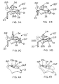
FIG. 5 shows a prior art nosepiece assembly, whereFIG. 5A is a side view of the nosepiece assembly andFIG. 5B is a rear view along line A-A ofFIG. 5A ; -
FIG. 6 illustrates a first embodiment of a nosepiece assembly according to the invention; -
FIG. 7 is a perspective view of the latch wire according to the invention; -
FIG. 8 is a rear view of the latch assembly along line B-B ofFIG. 6 ; -
FIG. 9 is a partial front view of a nosepiece assembly along line C-C ofFIG. 6 ; -
FIG. 10 is a partial front view of an alternate nosepiece assembly along line C-C ofFIG. 6 ; -
FIGS. 11, 12 and 13 show an improved contact trip according to the invention being used with different workpieces; -
FIG. 14 shows a no mar pad assembly for the contact trip according to the invention; -
FIG. 15 shows a second embodiment of a nosepiece assembly according to the invention, whereFIG. 15A is a side view of the nosepiece assembly, andFIG. 15B is a partial cross-sectional view along line A-A ofFIG. 15A ; -
FIG. 16 shows another embodiment of a nosepiece assembly according to the invention, whereFIG. 16A is a side view of the nosepiece assembly, andFIG. 16B is a cross-section along line A-A ofFIG. 16A ; -
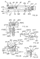
FIG. 17 is a perspective view of a first embodiment of a magazine assembly according to the invention; -
FIG. 18 is a partial cross-sectional view along plane A-A-A ofFIG. 17 ; -
FIG. 19 is a partial cross-sectional view of the magazine assembly ofFIG. 17 ; -
FIG. 20 illustrates a low nail indicator, whereFIG. 20A is a top view of the magazine ofFIG. 17 andFIG. 20B is a partial cross-sectional view thereof; -
FIG. 21 is a second magazine assembly according to the invention; -
FIG. 22 is a partial cross-sectional view along line A-A ofFIG. 21 ; -
FIG. 23 is a side view of the pusher assembly of the magazine assembly ofFIG. 21 ; -
FIG. 24 is a top view along line D-D ofFIG. 23 ; -
FIG. 25 is a partial cross-sectional view along line C-C ofFIG. 23 ; -
FIG. 26 is a partial cross-sectional view of the magazine assembly along line B-B inFIG. 21 ; -
FIG. 27A is an exploded view of a first embodiment of a belt hook assembly according to the invention; -
FIG. 27B is an exploded view of an alternate embodiment of a belt hook assembly; and -
FIG. 28 is another embodiment of the belt hook assembly according to the invention, whereFIG. 28A is a cross-sectional view along line A-A ofFIG. 1 , andFIG. 28B is an exploded view thereof. - The invention is now described with reference to the accompanying figures, wherein like numerals designate like parts.
FIG. 1 shows a fastener tool 10 comprising amain housing 15 which covers the driving mechanism (not shown) for driving a fastener, such as a nail or a staple, and which includes ahandle 11. The fastener tool 10 also comprises anosepiece assembly 30 below thehousing 15, amagazine assembly 40 connected to thenosepiece assembly 30 and thehandle 11, and atrigger assembly 20 disposed on thehousing 15 and/or handle 11 for activating the driving mechanism. Persons skilled in the art should recognize that the driving mechanism can be a pneumatic-based system, such as the ones shown inU.S. Patent Nos. 3,673,922 or5,181,450 , or an electric system, such as the ones shown inU.S. Patent No. 4,928,868 . The teachings from those patents are wholly incorporated herein by reference. - Referring to
FIGS. 1 and 2 , thetrigger assembly 20 may have amain trigger 21 pivotably attached to thehousing 15 or handle 11via pin 15P, and asupplemental trigger 22 pivotably attached to themain trigger 21 viapin 21P. As discussed below, whenmain trigger 21 andcontact trip 23 are activated,supplemental trigger 22 will movevalve 24, thus activating the driving mechanism. Persons skilled in the art will recognize thatvalve 24 will be a switch if the driving mechanism is an electric system, or an air flow-control valve if the driving mechanism is pneumatic system. -
FIGS. 2A-2C show the sequence for triggeringvalve 24.FIG. 2A is the initial state, wherevalve 24 is not triggered, and thecontact trip 23 andmain trigger 21 are not activated. InFIG. 2B ,contact trip 23 has been activated, i.e., the user has pushed fastener tool 10 unto a workpiece (not shown). At this time,valve 24 has not been triggered yet. InFIG. 2C ,valve 24 is triggered whenmain trigger 21 is activated by rotating themain trigger 21 aboutpin 15P. Persons skilled in the art will recognize that thevalve 24 was triggered because thecontact trip 23 pushed thesupplemental trigger 22 closer tovalve 24, andmain trigger 21 then moved thesupplemental trigger 22 closer to (thus triggering)valve 24. - Persons skilled in the art should recognize that
valve 24 would have been triggered regardless of the sequence of activation of either thecontract trip 23 ormain trigger 21. In other words,valve 24 would have been triggered wherecontact trip 23 was activated prior to activation oftrigger 21, or vice versa.Valve 24 also would have been triggered ifcontact trip 23 andmain trigger 21 were activated simultaneously. Persons skilled in the art will recognize that this trigger thus allows for a "bump mode." In other words, the user will be able to activate the driving mechanism by activatingmain trigger 21 and holdingmain trigger 21 in the activated position, while activating anddisactivating contact trip 23, i.e., bumping fastener tool 10 multiple times onto workpiece W. -
FIG. 3 shows an alternate trigger assembly 20'. The teachings of the previous embodiment are wholly incorporated herein by reference. InFIG. 3 , like numerals refer to like parts. Persons skilled in the art should recognizeFIG. 3 illustrates a "sequential" trigger assembly 20'. In other words, the trigger assembly 20' will only activatevalve 24 if thecontact trip 23 andmain trigger 21 are activated in a specific sequence. -
FIG. 3A shows the trigger assembly 20' in the deactivated mode where neithercontact trip 23 ormain trigger 21 have been activated.FIG. 3B shows activation ofcontact trip 23, thus movingsupplemental trigger 25, which is pivotally attached tomain trigger 21 viapin 21P.FIG. 3C shows activation ofvalve 24, whencontact trip 23 andmain trigger 21 are activated. Persons skilled in the art should recognize thatcontact trip 23 movessupplemental trigger 25 closer tovalve 24, andmain trigger 21 triggeredvalve 24 viasupplemental trigger 25 when it was pivoted aboutpin 15P. -
FIG. 3D shows the state of the trigger assembly 20' whenmain trigger 21 is kept activated in the activated position, butcontact trip 23 has been returned to the deactivated position. Persons skilled in the art should note thatbump 25B onsupplemental trigger 25 maintainsvalve 24 in the activated position. In other words,valve 24 has not been allowed to go back to its original position to reset. Accordingly, in a pneumatic system, the piston (not shown) would not return to its original position untilmain trigger 21,supplemental trigger 25 andvalve 24 are allowed to return to their original deactivated position. - Persons skilled in the art will recognize that, if the user maintains the
main trigger 21 in the activated position, the user will not be able to reactivatevalve 24 whencontact trip 23 is activated. This is becausecontact trip 23 will not contactsupplemental trigger 25 as agap 23G is created therebetween. - Similarly, persons skilled in the art will recognize that
contact trip 23 will not contactsupplemental trigger 25 if trigger assembly 20' is activated in the wrong sequence. In other words, if the user activatesmain trigger 21 and then activatescontact trip 23, the user will not be able to triggervalve 24 and thus fail to activate fastener tool 10. - Persons skilled in the art will recognize that it is preferable to provide a fastener tool 10 with one of the
trigger assemblies 20 or 20'. If the user prefers a specific mode, i.e., bump mode over sequential mode, the user can then replace the installed trigger assembly with the desired trigger assembly. It is also preferable to constructtrigger assemblies 20 and 20' with the same common parts, except forsupplemental trigger trigger assemblies 20, 20' sold to the user, themain trigger 21 andcontact trip 23, etc. will be the same. This reduces manufacturing costs, etc. -
FIG. 4 illustrates atrigger lock mechanism 26 for preventing undesired triggering ofmain trigger 21.Trigger lock 26 may be pivotally attached aroundvalve 24 so that it pivots aboutvalve 24. Preferably, triggerlock 26 is substantially shaped like a ring.Trigger lock 26 may have at least one protrusion, includinglock 26L. Thislock 26L may be moved between locking position (as shown inFIG. 4A ) and bypassed position (as shown inFIG. 4B ). When trigger lock 26 is rotated towards the locking position, lock 26L will be disposed betweentrigger 21 andhousing 15 and/or handle 11. Accordingly, if a user attempts to activatemain trigger 21,trigger 21 will contactlock 26L and not move the necessary distance to activatevalve 24. - On the other hand, if trigger lock 26 is rotated to the bypassing position,
main trigger 21 will not contactlock 26L, thus allowingtrigger 21 to activatevalve 24. - It may also be preferable to provide
trigger lock 26 withprotrusion 26T to facilitate the rotation oftrigger lock 26.Such protrusion 26T preferably has some texture thereon to provide a good finger grip for rotating thetrigger lock 26 with his or her fingers. -
FIGS. 6-8 illustrate animproved nosepiece assembly 30, where like numerals shown inFIG. 5 refer to like parts. Unlike the prior art nosepiece assembly ofFIG. 5 ,spring 36, which is disposed betweenhook 31H and latch 33, has at least twobends nosepiece 31 hascutout 31C for allowingbend 36A to extend beyondnosepiece cover 32. By providingspring 36 with at least two bends preferably on each side of thenosepiece assembly 30, the load stress concentrations onspring 36 are dissipated. -
Spring 36 may also have athird bend 36C, which follows the contour ofnosepiece cover 32, wherebend 36C follows the shape ofrib 32R onnosepiece cover 32. Persons skilled in the art will recognize that havingspring 36 follow the contour ofnosepiece cover 32 will not obstruct the user's sight of the operation. By keeping thespring 36 relatively close to the door, it also reduces the risk of damage to thespring 36 if the fastener tool 10 is accidentally dropped. - In addition, the
ends 36E ofspring 36 may be inserted intolatch 33 and bent downwardly towardnosepiece end 31E. Persons skilled in the art should recognize thatend 36E may be bent prior to insertion intolatch 33. Such feature facilities assembly and obviates the need for a swaging operation. -
FIGS. 9 and 10 illustrate the inside ofnosepiece 31, where like numerals refer to like parts. As shown inFIGS. 9 and 10 ,contact trip 27 extends throughnosepiece 31 until it extends beyond theend 31E ofnosepiece 31. Theend 27E curves back and extends intonosepiece 31.Nosepiece 31 preferably has achannel 27C for allowing movement ofcontact trip 27 along such channel when the fastener tool 10 is depressed ontoworkpiece W. Nosepiece 31 may have a channel 31CC for allowing the driver element in the driving mechanism to extend therethrough and push a nail out towards theend 31E. Nails may be introduced into channel 31CC via opening 31O. - As shown in
FIG. 10 , it may be preferable to provide aretainer 31R onto channel 31CC.Such retainer 31R prevents the nail which enters channel 31CC from moving beyond channel 31CC, for example, when nosepiece cover 32 is open. - Referring to
FIGS. 1 and11-13 ,lower contact trip 27 is connected to contacttrip 23. Typically,contact trip 27 has a bent wire that wraps around the front ofnosepiece assembly 30. Such arrangement obstructs the view of the contact between thenosepiece assembly 30 and the workpiece W. Typically, such wire forms are also substantially flat, so when the fastener tool 10 is angled with respect to the work, the nail or staple is not fully introduced into the workpiece W, thus leaving an exposed head. - The
improved contact trip 27 resolves such problems by providinglower portion 27R, which extends downwardly along the sides of the nosepiece and forwardly away frommagazine assembly 40, extending beyondnosepiece cover 32.Lower portion 27R then extends rearwardly in a curve towardsmagazine assembly 40 and wrap around the rear ofnosepiece assembly 30. Persons skilled in the art will recognize that such arrangement provides a sight line S which allows the user to see the contact between thenosepiece assembly 30 and workpiece W. - Preferably,
lower portion 27 is rounded, rather than flat. Accordingly, the fastener tool 10 will be triggered equally well when used with complex molding. As shown inFIG. 11 , thefront portion 27F ofportion 27R will activatecontact trip 27 when it contacts workpiece W. In other words,contact trip 27 will be activated when fastener tool 10 is disposed on molding from the inside of the molding. - Similarly, a rear portion 27RR of
portion 27R will activatecontact trip 27 when the fastener tool 10 is disposed on a complex molding and fastener tool is contacting the workpiece from the outside of the trim as shown inFIG. 12 . Finally, as shown inFIG. 13 , having a roundedportion 27R allows trigger activation ofcontact trip 27 regardless of the angle of contact between the fastener tool 10 and workpiece W. -
FIG. 14 illustrates no mar assembly oncontact trip 27. The no mar assembly comprisespiece 28, which is preferably stamped and bent so that it clamps onto roundedportion 27R ofcontact trip 27. Preferably,piece 28 is made of sheet metal. As shown inFIG. 14 ,piece 28 may haverear hook 28R for hooking onto therear portion 27R. Similarly,piece 28 may havefront hooks 28F for latching onto thefront portion 27F ofcontact trip 27. Persons skilled in the art shall recognize that there are twofront hooks 28F. It may also be preferable to apply aband 29 ontopiece 28. Preferably,band 29 is bonded to the bottom and sides ofpiece 28 to protect the workpiece W from the roundedportion 27R when the fastener tool 10 is depressed onto workpiece W. Preferablyband 29 is made of polyurethane. -
FIGS. 15A-15B show an alternate nail retainer mechanism, where like numerals refer to like parts. In this embodiment,nosepiece cover 32 is provided with astop 32S thereon. Said stop 32S contacts nosepiece 31 when nosepiece cover 32 is rotated to provide access intonosepiece 31. When nosepiece cover 32 is rotated, stop 32S approachesnosepiece 31 until contact is achieved. When contact exists betweenstop 32S andnosepiece 31,nosepiece cover 32 cannot rotate any further.Stop 32S may prevent movement ofnosepiece cover 32 beyond 90 degrees offnosepiece 31. Preferably, the maximum angle betweennosepiece 31 andnosepiece cover 32 is equal to or less than about 45 degrees. Becausenosepiece 32 cannot rotate any further,nails 9, which may be moving out towardsnosepiece cover 32 will not be able to move forwardly beyondnosepiece cover 32. In other words,nails 9 have been retained betweennosepiece cover 32 andnosepiece 31. Persons skilled in the art should recognize that it is preferable to provide areference 31R as shown inFIG. 10 in addition to thestop 32S. - Preferably,
nosepiece 31 may have a retainer 31G, which receivescontact trip 27 therethrough and substantially surroundscontact trip 27. Preferably, retainer 31G has a substantially C-shaped cross-section. Retainer 31G minimizes movement ofcontact trip 27 along any direction other than vertically. -
FIGS. 16A-16B show another nosepiece assembly, where like numerals refer to like parts. In this embodiment,contact trip 27 has a retainer 27NR, which receivesnosepiece protrusion 31X therethrough, and substantially surroundsnosepiece protrusion 31X. Preferably, retainer 27NR has a substantially C-shaped cross-section. Retainer 27NR minimizes movement ofcontact trip 27 along any direction other than vertically. This is because retainer 27NR forces contacttrip 27 to slide alongnosepiece protrusion 31X. - An alternate embodiment of
contact trip 27 is shown inFIG. 15 . In this embodiment, thecontact trip 27 has aportion 27P which may comprise of polymer such as polyurethane, or rubber molded overcontact trip 27. Persons skilled in the art will recognize that such structure will provide an alternate no mar pad as discussed before. -
FIGS. 17-19 illustrate a first embodiment ofmagazine assembly 40.Magazine assembly 40 comprisesextrusion 41, which is substantially C-shaped. Persons skilled in the art should recognize thatextrusion 41 is preferably made of plastic and/or metal, etc. -
Extrusion 41 may have a substantially horizontal top wall 41P, a substantially horizontalbottom wall 41B, and anail loading space 41S defined between the top andbottom walls 41P, 41B for loadingnails 9 therein. Persons skilled in the art should recognize thatnail loading space 41S preferably has grooves 41G for engaging the heads ofnails 9. Persons skilled in the art shall recognize that grooves 41G are disposed at different heights alongspace 41S to engagenails 9 having different heights. -
Magazine assembly 40 also has a slidingdoor 43 moveable between the top andbottom walls 41P, 41B.Extrusion 41 may have a divider rail 41D extending downwardly from top wall 41P. In addition,extrusion 41 may have a rail 41R extending upwardly frombottom wall 41B. Rail 41R is preferably made of metal, such as steel, etc. Rail 41R is preferably disposed under thenails 9 to preventnails 9 from scratchingbottom wall 41B. - Persons skilled in the art will recognize that
rails 41B, 41R extend intonail loading space 41 S. Persons skilled in the art will also recognize that rail 41D is preferably part of theextrusion 41. Persons skilled in the art should also recognize that rail 41R may be provided on the top ofnail loading space 41S, while rail 41D may be provided on the bottom ofnail loading space 41 S. - Rails 41D, 41R preferably divide the
nail loading space 41 S into two channels: the pusher channel 41PC and door channel 41C. Pusher channel 41PC is closest to the side wall 41SW.Nails 9 andpusher 44 preferably slide along channel 41PC. Door channel 41C slidingly receivesdoor 43. - As mentioned above, a
pusher 44 is slidingly disposed in pusher channel 41PC for pushingnails 9.Pusher 44 may have protrusions 44G that ride along grooves 41G (seeFIG. 20A ).Pusher 44 is preferably biased towards the front of themagazine assembly 40.Pusher 44 may be biased accordingly by providingpusher 44 withprotrusions 44P, which extend through slidingdoor 43 into at least onecylinder 43C ofdoor 43. Aspring 43 is disposed incylinder 43C and trapped betweenprotrusion 44P and the back wall 43CW ofcylinder 43C. - To prevent
pusher 44 from extending intonosepiece 31,door 43 may be provided with a stop pin 43SP for contactingprotrusions 44P. Persons skilled in the art shall recognize that the stop pin 43SP can be disposed anywhere along the length ofcylinder 43C. It is nevertheless preferable to dispose stop pin 43SP in a position where it stopspusher 44 prior to enteringnose piece 31. -
Protrusion 44P may have a colored portion. As thepusher 44 moves towards the front ofmagazine assembly 40, the colored portion will appear throughwindow 43W disposed orcylinder 43C. This alerts the user that number ofnails 9 disposed withinnail loading space 41 S is low. - As mentioned above,
door 43 is slidingly disposed withmagazine assembly 40. If a user wants to load nails withinspace 41 S, the user needs to retract slidingdoor 43 rearwardly, exposingspace 41 S. The user then disposesnails 9 therein, and closes thedoor 43C. It is preferable to provide alock 43L ondoor 43 to fix the position of slidingdoor 43 relative toextrusion 41.Such lock 43L is preferably pivotably attached to door 43 via pin 43LP.Lock 43L may have aprotrusion 43P which extends through thenail loading space 41S and engages ahole 41H onside wall 41 SW, thus lockingdoor 43. - In addition,
lock 43L may have a tab 43LP for actuating thelock 43L. Preferably, a spring 43LS is disposed to bias lock 43L towards the locking position. Persons skilled in the art may recognize that spring 43LS may be disposed between tab 43LP and 43L to bias thelock 43L towards the locking position. - A second low nail indicator may be provided in
magazine assembly 40. Referring toFIGS. 17-20 , it is preferable to provide awindow 41W in top wall 41P. Anindicator 46 may slide under top wall 41P. Preferably,indicator 46 has a coloredportion 461 to denote a low nail condition.Indicator 46 may have atab 46T that engagestab 44T ofpusher 44. Preferably,indicator 46 is biased towards the rear ofmagazine assembly 40 by the spring 46S. Accordingly, aspusher 44 travels towardsnosepiece 31,pusher 44slides indicator 46 towards the front ofmagazine assembly 40 via the connection betweentabs pusher 44 gets closer to nosepiece 31, thecolored portion 461 will be visible throughwindow 41 W, informing the user that the number of nails withinspace 41 S is low. - Persons skilled in the art shall recognize that
magazine assembly 40 is preferably fixedly attached tonose piece 31 viascrews 42 as shown inFigure 1 .Screws 42 extend throughfront wall 41 S viaholes 42H. - Referring to
FIGS. 21-26 illustrate an alternate magazine assembly 40' may comprise anupper magazine 45 and alower magazine 46 fixedly attached toupper magazine 45 viascrews 45B. Magazine assembly 40' may be attached tonose piece 31 viascrews 42 extending throughfront wall 41F. -
Upper magazine 45 is molded and may be made of plastic or metal.Lower magazine 46 may also be molded and preferably made from metal or plastic, etc. -
Upper magazine 45 may haverail 45R connected thereto.Rail 45R is preferably C-shaped and receives the heads ofnails 9 within channel 45NC. Preferablyrail 45R is made of metal. -
Lower magazine 46 preferably has two channels: nail channel 46NC, which is preferably aligned with channel 45NC, and pusher channel 46PC.Lower magazine 46 may also have at least onerib 46R for strengtheninglower magazine 46. -
Pusher assembly 47 may have acarriage 47C which slides alongrail 45R.Carriage 47C is preferably biased towards the front of magazine assembly 40' via aleaf spring 49 disposed innosepiece 31,housing 15 or magazine assembly 40'.Carriage 47C may have a pin 47PP which preferably extends downwardly into channel 46PC. - Upper pusher 47UP may be pivotably attached to pin 47PP. Preferably, a
spring 47S is disposed around pin 47PP. One end of thespring 47S contacts upper pusher 47UP for biasing the upper pusher 47UP towards the nail channel 46NC. Upper pusher 47UP may also have a tab 47UPP for allowing the user to rotate upper pusher 47UP, as well as move thepusher assembly 47 alongrail 45R. -
Lower pusher 47P may be provided underneath upper pusher 47UP. Preferably,lower pusher 47P is pivotably attached to pin 47PP.Lower pusher 47P may also be biased towards nail channel 46NC by thespring 47S. - Persons skilled in the art shall recognize that
lower pusher 47P has contact surface 47PC for contactingnails 9 and pushingnails 9 towardnosepiece 31. -
Lower pusher 47P may also have a camming surface 47PCS, which is preferably behind contact surface 47PC. If the user introducesnails 9 into magazine assembly 40' throughinput 461,nails 9 will travel along channel 46NC until they contact camming surface 47PCS. The user then retractspusher assembly 47 rearwardly by pulling on tab 47UPT. As thepusher assembly 47 is traveling rearwardly, camming surface 47PCS will slide alongnails 9 and pivotlower pusher 47P about pin 47PP to bypassnails 9. Persons skilled in the art will recognize thatlower pusher 47P will have at least one surface contacting thenails 9 as it travels rearwardly. When therearmost nails 9 is bypassed, thespring 47S will forcelower pusher 47P back into nail channel 46NC and into contact with therearmost nail 9, thus once again biasing thenails 9 towardsnosepiece 31 when the user releases or lets go of the upper pusher 47UP. - A magazine assembly 40' may have a
nail retainer 48 which retainsnails 9 within channel 46NC even if thenails 9 have not yet been bypassed bypusher assembly 47.Retainer 48 may be a resilient piece, preferably made of metal.Retainer 48 preferably has acamming surface 48C facing the rear of magazine 40', and a retainingsurface 48R facing the front of magazine 40'. Accordingly, asnails 9 are introduced into magazine assembly 40' via theinput 461, thenails 9 will move alongsurface 48C, pushretainer 48 towards pusher channel 46PC, and when the rearmost nail has bypassedretainer 48,retainer 48 will snap back into channel 46NC. The nails will not be able to exit the channel 46NC via theinput 461 because of theretainer surface 48R. Preferably,retainer 48 is held in place via two bosses 46RR disposed onlower magazine 46. Another end ofretainer 48 may be anchored and extend through a wall oflower magazine 46. -
Lower magazine 46 may haveprotrusion 47B, which contactslower pusher 47P as it moves towards the front of magazine assembly 40', causing contact surface 47PC to move into channel 46PC. Preferably,protrusion 47B is placed so thatpusher 47P is rotated prior to contact surface47PC entering nosepiece 31 and channel 31CC. Preferably,nosepiece 31 may have pusher bypass area 31PB for allowingpusher 47P to move laterally and avoid contact with the driver mechanism (seeFIGS. 9 and 10 ). Persons skilled in the art will recognize that a user may push tab 47PT to move contact surface 47PC into bypass area 31PB. -
Lower pusher 47P may have a tab 47PT, which may be pushed by the user to move the contact surface 47PC into channel 46PC. Tab 47PT may have a ramp 47PR that will contacttab 45T disposed on the rear of magazine assembly 40', whenlower pusher 47P is moved rearwardly and reaches the rear of magazine assembly 40'. As ramp 47PR moves alongtab 45T,lower pusher 47P will pivot, moving contact surface 47PC into channel 46PC, allowingnails 9 to move into channel 46NC. - Alternatively, tab 47PT may have protrusions 47PPT which engage
tab 45T disposed on the rear of magazine assembly 40'. Accordingly, when the user movespusher assembly 47 to the rear of magazine assembly 40',tab 45T and protrusions 47PPT engage to retainpusher assembly 47 in the rearmost position, facilitating the insertion ofnails 9 into magazine assembly 40'. -
Upper pusher 47 may also maintainpusher assembly 47 in a rearmost position. This can be done by providingupper magazine 45 with alock channel 45L which receives the lock 47UPL. In order to unlockpusher assembly 47, the user would push on tab 47UPT and rotate lock 47UPL out oflock channel 45L. Preferably,rib 46R is long enough to prevent inadvertent or undesired pushing on tab 47UPT, which would thus unlock upper pusher 47UP. - Persons skilled in the art will recognize that
pusher 47 allows the user to manipulate magazine assembly 40' in two manners. First, the user can insert thenails 9 into magazine assembly 40', then pull thepusher assembly 47 rearwardly.Lower pusher 47P would bypassnails 9 and rotate into the pushing position after the rearmost nail has been bypassed. This is commonly known as a "load and cock" operation. - Alternatively, the user can pull the
pusher assembly 47 rearwardly and lock it in place as described above, then loadnails 9, andrelease pusher assembly 47, wherepusher 47P would then contact therearmost nail 9. This is commonly known as a "cock and load" operation. Persons skilled in the art will also recognize that locking thepusher assembly 47 in the rear of magazine assembly 40' will facilitate loading and/or unloading ofnails 9. - Referring to
FIGS. 1 and27-28 , it is preferable to provide fastener tool 10 with a belt hook assembly. Referring toFIG. 27A , abelt hook assembly 50 is preferably disposed onhandle 11.Belt hook assembly 50 may includebelt hook 51 disposed betweenhandle 11 and rear portion 11R. Portion 11R may be fixedly attached intohandle 11 via screws 11S. -
Belt hook 51 may have ahook portion 51H, which preferably extends substantially parallel to the longitudinal axis ofhandle 11.Belt hook 51 may be made of wire.Belt hook 51 is preferably made of a single piece of wire welded into a continuous loop. Preferably, the wire has a diameter of about 4mm.Hook portion 51H is preferably shaped in an oblong oval shape with a rounded end to facilitate slipping thebelt hook 51 onto a tool belt. -
Belt hook 51 may have a notch 51N for receiving a detent protrusion 11D disposed onhandle 11. Preferably, handle 11 has at least two detent protrusions 11D. Protrusions 11D and notch 51N can be disposed so that thehook 51 is movable leftwardly of thehandle 11, rightwardly of thehandle 11 and/or upwardly ofhandle 11. Persons skilled in the art will recognize that the detents protrusion 11D and notch 51N may be provided for any other desired hook positions. -
FIG. 27B shows another hook assembly 50' where like numerals refer to parts. In this embodiment,detent ring 52 may be disposed betweenhook 51 and rear portion 11R.Ring 52 may have adetent protrusion 52D, which engages notches 51N on thehook 51. Persons skilled in the art shall recognize thatring 52 may be disposed instead betweenhandle 11 andhook 51. -
FIG. 28 shows a thirdbelt hook assembly 50". Preferably,belt hook assembly 50" is made of plastic molded over steel. Persons skilled in the art will recognize that hook 53B may be disposed around handle 11. Thehandle 11 may have a protrusion 11D, which engagesdetent notch 53N and is disposed inside ofbelt hook 53. Persons skilled in the art should recognize that thedetent notches 53N and protrusions 11D may be disposed to select the number of available positions forbelt hook 53. As shown inFIG. 28 ,belt hook 53 preferably has at least fournotches 53 so that thebelt hook 53 can be disposed leftwardly, rightwardly, downwardly and upwardly ofhandle 11. Persons skilled in the art should recognize that by placinghook 53 downwardly ofhandle 11, the user will have placedhook 53 in a storage position. - Persons skilled in the art will recognize that protrusions 11D may extend substantially parallel to the longitudinal axis of handle 11 (as shown in
FIG. 27 ), or substantially perpendicular to the longitudinal axis of handle 11 (as shown inFIG. 28 ). - Persons skilled in the art should recognize that handle 11 can be designed so that an air seal between rear-portion 11R and handle 11 must be broken in order to remove
belt hook assembly 50, 50'. Alternatively, handle 11 can be designed so that no air seal is broken betweenhandle 11 and nut 11N (seeFIGS. 1 and28B ) when removingbelt hook assembly 50". As shown inFIG. 28B , the air input 11PI is directly connected to handle 11.Handle 11 has threads 11NT for threadingly engaging nut 11N.Belt hook assembly 50" is thus disposed betweenhandle 11 and nut 11N without requiring an air seal therebetween. - Persons skilled in the art may recognize other alternatives to the means disclosed herein. However, all these additions and/or alterations are considered to be equivalents of the present invention.
Claims (5)
- A magazine for a fastener tool having a nosepiece and a driving mechanism for driving a fastener through the nosepiece, the magazine comprising:a magazine body having a first end portion coupled to the nosepiece and a second end portion away from the first end portion, the magazine body configured to receive fasteners; anda pusher assembly coupled to the magazine body and biased toward the first end portion to push the fasteners toward the nosepiece,wherein the magazine body and pusher assembly are configured to allow loading of fasteners into the magazine body in a first mode and in a second mode,the first mode comprising inserting fasteners into the magazine, followed by moving the pusher assembly toward the second end portion to bypass the fasteners and engage the fastener farthest from the first end portion, andthe second mode comprising locking the pusher assembly near the second end portion of the magazine, followed by inserting fasteners into the magazine and releasing the pusher assembly to engage the fastener farthest from the first end portion.
- The magazine of claim 1 wherein the magazine body defines a fastener channel for receiving the fasteners, and a pusher channel for receiving the pusher assembly.
- The magazine of claim 2 wherein the pusher assembly comprises a camming surface to facilitate bypassing the fasteners in the first mode of operation.
- The magazine of claim 3 wherein at least one of the magazine body and pusher assembly comprise a locking mechanism to facilitate locking the pusher assembly in the second mode of operation.
- The magazine of claim 4 wherein the locking mechanism comprises at least one indentation on the magazine body near the second end of the magazine body.
Applications Claiming Priority (4)
| Application Number | Priority Date | Filing Date | Title |
|---|---|---|---|
| US26689301P | 2001-02-07 | 2001-02-07 | |
| US10/057,476 US20020117531A1 (en) | 2001-02-07 | 2002-01-24 | Fastener tool |
| EP02250836A EP1231028A3 (en) | 2001-02-07 | 2002-02-07 | Fastener tool |
| EP09163587A EP2098338B1 (en) | 2001-02-07 | 2002-02-07 | Fastener Tool |
Related Parent Applications (2)
| Application Number | Title | Priority Date | Filing Date |
|---|---|---|---|
| EP02250836.0 Division | 2002-02-07 | ||
| EP09163587.0 Division | 2009-06-24 |
Publications (3)
| Publication Number | Publication Date |
|---|---|
| EP2269779A2 true EP2269779A2 (en) | 2011-01-05 |
| EP2269779A3 EP2269779A3 (en) | 2011-04-20 |
| EP2269779B1 EP2269779B1 (en) | 2012-05-23 |
Family
ID=26736545
Family Applications (8)
| Application Number | Title | Priority Date | Filing Date |
|---|---|---|---|
| EP10186081A Expired - Lifetime EP2269777B1 (en) | 2001-02-07 | 2002-02-07 | Fastener tool |
| EP10186084A Expired - Lifetime EP2269779B1 (en) | 2001-02-07 | 2002-02-07 | Magazine assembly for fastener tool |
| EP10186072A Expired - Lifetime EP2269774B1 (en) | 2001-02-07 | 2002-02-07 | Fastener tool |
| EP10186078A Expired - Lifetime EP2269776B1 (en) | 2001-02-07 | 2002-02-07 | Magazine assembly for a fastener tool |
| EP09163587A Expired - Lifetime EP2098338B1 (en) | 2001-02-07 | 2002-02-07 | Fastener Tool |
| EP10186075A Expired - Lifetime EP2269775B1 (en) | 2001-02-07 | 2002-02-07 | Fastener tool |
| EP02250836A Withdrawn EP1231028A3 (en) | 2001-02-07 | 2002-02-07 | Fastener tool |
| EP10186082A Expired - Lifetime EP2269778B1 (en) | 2001-02-07 | 2002-02-07 | Magazine assembly for a fastener tool |
Family Applications Before (1)
| Application Number | Title | Priority Date | Filing Date |
|---|---|---|---|
| EP10186081A Expired - Lifetime EP2269777B1 (en) | 2001-02-07 | 2002-02-07 | Fastener tool |
Family Applications After (6)
| Application Number | Title | Priority Date | Filing Date |
|---|---|---|---|
| EP10186072A Expired - Lifetime EP2269774B1 (en) | 2001-02-07 | 2002-02-07 | Fastener tool |
| EP10186078A Expired - Lifetime EP2269776B1 (en) | 2001-02-07 | 2002-02-07 | Magazine assembly for a fastener tool |
| EP09163587A Expired - Lifetime EP2098338B1 (en) | 2001-02-07 | 2002-02-07 | Fastener Tool |
| EP10186075A Expired - Lifetime EP2269775B1 (en) | 2001-02-07 | 2002-02-07 | Fastener tool |
| EP02250836A Withdrawn EP1231028A3 (en) | 2001-02-07 | 2002-02-07 | Fastener tool |
| EP10186082A Expired - Lifetime EP2269778B1 (en) | 2001-02-07 | 2002-02-07 | Magazine assembly for a fastener tool |
Country Status (2)
| Country | Link |
|---|---|
| US (3) | US20020117531A1 (en) |
| EP (8) | EP2269777B1 (en) |
Families Citing this family (47)
| Publication number | Priority date | Publication date | Assignee | Title |
|---|---|---|---|---|
| US7641089B2 (en) * | 2004-04-02 | 2010-01-05 | Black & Decker Inc. | Magazine assembly for nailer |
| US8408327B2 (en) | 2004-04-02 | 2013-04-02 | Black & Decker Inc. | Method for operating a power driver |
| US7213732B2 (en) * | 2004-04-02 | 2007-05-08 | Black & Decker Inc. | Contact trip mechanism for nailer |
| US7137541B2 (en) | 2004-04-02 | 2006-11-21 | Black & Decker Inc. | Fastening tool with mode selector switch |
| US7285877B2 (en) | 2004-04-02 | 2007-10-23 | Black & Decker Inc. | Electronic fastening tool |
| DE602005006462D1 (en) | 2004-04-02 | 2008-06-19 | Black & Decker Inc | Fixing tool with mode selector switch |
| US7699201B2 (en) * | 2004-05-25 | 2010-04-20 | Black & Decker Inc. | Fastening tool with automatic feeding of wire-collated fasteners |
| WO2006012516A2 (en) * | 2004-07-23 | 2006-02-02 | Acco Brands Usa Llc | Low staple indicator for a stapler |
| CN100339188C (en) * | 2004-10-25 | 2007-09-26 | 力偕实业股份有限公司 | Highly stable nailing channel cap structure of pin gun |
| US20060091176A1 (en) * | 2004-10-29 | 2006-05-04 | Cannaliato Michael F | Cordless fastening tool nosepiece with integrated contact trip and magazine feed |
| US7866521B2 (en) * | 2004-12-03 | 2011-01-11 | Black & Decker Inc. | Magazine for wired-collated fasteners with automatic loading |
| US7137186B2 (en) * | 2004-12-03 | 2006-11-21 | Black & Decker Inc. | Magazine for wired-collated fasteners with automatic loading |
| US7950556B2 (en) * | 2005-03-16 | 2011-05-31 | Black & Decker Inc. | Coil nail spreader |
| KR200389873Y1 (en) * | 2005-04-20 | 2005-07-18 | 제일타카 주식회사 | Tacker apparatus with a nail stopper |
| JP4923440B2 (en) * | 2005-05-25 | 2012-04-25 | マックス株式会社 | Contact arm mechanism for driving tool |
| US8074855B2 (en) | 2006-04-20 | 2011-12-13 | Illinois Tool Works Inc. | Bypass type follower assembly having a latch mechanism on the follower claw |
| US7942299B2 (en) * | 2006-05-31 | 2011-05-17 | Black & Decker Inc. | Hand tool with belt or rafter hook |
| US7753243B2 (en) * | 2006-10-25 | 2010-07-13 | Black & Decker Inc. | Lock-out mechanism for a power tool |
| DE102006035460A1 (en) * | 2006-11-27 | 2008-05-29 | Hilti Ag | Hand-guided tacker |
| US8225978B2 (en) | 2007-02-01 | 2012-07-24 | Black & Decker Inc. | Multistage solenoid fastening tool with decreased energy consumption and increased driving force |
| US7537145B2 (en) | 2007-02-01 | 2009-05-26 | Black & Decker Inc. | Multistage solenoid fastening device |
| US7646157B2 (en) | 2007-03-16 | 2010-01-12 | Black & Decker Inc. | Driving tool and method for controlling same |
| US7413105B1 (en) * | 2007-03-22 | 2008-08-19 | Apach Industrial Co., Ltd. | Pushing device of drawer type magazine for nail gun |
| US8376204B2 (en) * | 2007-05-04 | 2013-02-19 | Illinois Tool Works Inc. | Side load magazine for a fastener drivers |
| US8899460B2 (en) * | 2007-06-12 | 2014-12-02 | Black & Decker Inc. | Magazine assembly for nailer |
| US8931676B2 (en) | 2007-08-27 | 2015-01-13 | Black & Decker Inc. | Nailer having mechanism for pre-positioning nail |
| DE102007047241A1 (en) * | 2007-09-24 | 2009-04-02 | Adolf Würth GmbH & Co. KG | Stud gun |
| US8800835B2 (en) | 2008-07-17 | 2014-08-12 | Stanley Fastening Systems, Lp | Fastener driving device with mode selector and trigger interlock |
| US9259832B2 (en) * | 2010-08-25 | 2016-02-16 | Makita Corporation | Handheld electrical power tools |
| US9522464B2 (en) * | 2011-05-16 | 2016-12-20 | Illinois Tool Works Inc. | Multi-position utility hook assembly for a tool |
| ITBO20110303A1 (en) * | 2011-05-25 | 2012-11-26 | Fasco Srl | LOADER DEVICE FOR NAILER AND SIMILAR |
| US8998057B2 (en) | 2011-08-19 | 2015-04-07 | Techtronic Power Tools Technology Limited | Hook assembly for use with a power tool |
| US8723060B2 (en) | 2011-12-21 | 2014-05-13 | Robert Bosch Tool Corporation | Method and mechanism for power tool lock-off |
| CA2915513C (en) | 2012-06-18 | 2020-08-18 | Quick Grip Staples (Hk) Limited | An accessory for a fastening gun |
| CN208289826U (en) | 2015-02-06 | 2018-12-28 | 米沃奇电动工具公司 | Using gas spring as the fastener driver of power |
| JP6819045B2 (en) * | 2016-01-26 | 2021-01-27 | 工機ホールディングス株式会社 | Driving machine |
| US10668608B2 (en) | 2016-02-10 | 2020-06-02 | Illinois Tool Works Inc. | Fastener driving tool |
| US10377027B2 (en) * | 2016-03-07 | 2019-08-13 | Tsung-Wen Huang | Composite staple magazine for tackers |
| CN108058136B (en) * | 2016-11-09 | 2022-07-05 | 创科无线普通合伙 | Gas spring fastener driver |
| USD854820S1 (en) | 2017-11-14 | 2019-07-30 | Illinois Tool Works Inc. | Fastener driving tool belt hook |
| USD855431S1 (en) | 2017-11-14 | 2019-08-06 | Illinois Tool Works Inc. | Fastener driving tool pipe hook |
| US10926391B2 (en) | 2017-11-14 | 2021-02-23 | Illinois Tool Works Inc. | Powered fastener driving tool having hook assemblies |
| EP3720658B1 (en) | 2017-12-07 | 2023-10-18 | Black & Decker, Inc. | Nosepiece latch mechanism for a fastening tool |
| US10759034B2 (en) * | 2018-02-15 | 2020-09-01 | James Hardie Technology Limited | Systems and methods for fastening a component to a building substrate |
| JP7419727B2 (en) * | 2019-09-27 | 2024-01-23 | 工機ホールディングス株式会社 | driving machine |
| DE102020122342A1 (en) * | 2020-08-26 | 2022-03-03 | Raimund Beck Nageltechnik Gmbh | Nailer and kit for attaching to a nailer |
| EP4281253A1 (en) | 2021-01-20 | 2023-11-29 | Milwaukee Electric Tool Corporation | Powered fastener driver |
Citations (3)
| Publication number | Priority date | Publication date | Assignee | Title |
|---|---|---|---|---|
| US3673922A (en) | 1966-12-19 | 1972-07-04 | Fastener Corp | Fastener driving tool |
| US4928868A (en) | 1983-03-17 | 1990-05-29 | Duo-Fast Corporation | Fastener driving tool |
| US5181450A (en) | 1991-05-16 | 1993-01-26 | Umberto Monacelli | Pneumatic fastener driving apparatus with piston holding detent |
Family Cites Families (68)
| Publication number | Priority date | Publication date | Assignee | Title |
|---|---|---|---|---|
| US3727821A (en) * | 1967-11-24 | 1973-04-17 | Acme Lane Co Inc | Tool for attaching improved wing headed fasteners |
| US3615049A (en) * | 1969-09-15 | 1971-10-26 | Fastener Corp | Fastener driving tool |
| US3784077A (en) * | 1972-05-05 | 1974-01-08 | Textron Inc | Portable pneumatic fastener driving device with improved actuating mechanism |
| US4040554A (en) * | 1972-12-06 | 1977-08-09 | Haytayan Harry M | Pneumatic apparatus |
| US4264028A (en) * | 1979-05-03 | 1981-04-28 | Duo-Fast Corporation | Locking mechanism for a trigger of a fastener driving tool |
| US4436236A (en) * | 1982-03-22 | 1984-03-13 | Senco Products, Inc. | Front gate and latch assembly for the guide body of an industrial fastener driving tool |
| US4787145A (en) * | 1987-03-09 | 1988-11-29 | Klicker Garry L | Two position portable power tool hanger stabilized by spring and detent |
| US4793063A (en) * | 1987-03-31 | 1988-12-27 | Ducret Lucien C | Punch gun |
| DE3715293A1 (en) * | 1987-05-08 | 1988-12-01 | Haubold Kihlberg Gmbh | Device for driving-in fastening means |
| GB8800909D0 (en) * | 1988-01-15 | 1988-02-17 | Ethicon Inc | Gas powered surgical stapler |
| IT215948Z2 (en) * | 1988-12-02 | 1991-03-20 | Fasco Spa | MAGAZINE FOR PNEUMATIC NAILER PISTOL AND STICK OF NAILS SUITABLE TO BE EXPELLED FROM THE SAID GUN |
| US4913332A (en) * | 1989-01-23 | 1990-04-03 | Swingline Inc. | Sheath release device for stapler |
| JPH04365567A (en) * | 1991-06-12 | 1992-12-17 | Makita Corp | Pusher device for nail driver |
| US5372206A (en) * | 1992-10-01 | 1994-12-13 | Makita Corporation | Tightening tool |
| US5297713A (en) * | 1993-03-31 | 1994-03-29 | Stanley-Bostitch, Inc. | Rear load magazine assembly |
| US5335800A (en) * | 1993-07-06 | 1994-08-09 | Liu Chung Ho | Magazine for rivet gun |
| US5332156A (en) * | 1993-10-25 | 1994-07-26 | Ransburg Corporation | Spray gun with removable cover and method for securing a cover to a spray gun |
| JP3419535B2 (en) * | 1994-03-11 | 2003-06-23 | 株式会社マキタ | Nailing machine |
| US5433367A (en) * | 1994-11-28 | 1995-07-18 | Liu; Park | Magazine assembly for a fastener driving tool |
| US5676285A (en) * | 1995-06-07 | 1997-10-14 | Vinarsky; Michael A. | Hanger-clip accessory for sports bottle |
| US5687897A (en) * | 1995-07-28 | 1997-11-18 | Campbell Hausfeld/Scott Fetzer Company | Dual mode pneumatic tool |
| US5626274A (en) * | 1996-02-05 | 1997-05-06 | Illinois Tool Works Inc. | Nail strip magazine with spring leaf to bias feeding member and to separate nail strips |
| JPH1015852A (en) * | 1996-07-09 | 1998-01-20 | Makita Corp | Structure for attaching hook in power tool |
| US5692663A (en) * | 1996-07-11 | 1997-12-02 | Testo Industry Corp. | Trigger structure |
| US5813588A (en) * | 1996-10-09 | 1998-09-29 | Lin; George | Magazine assembly for fastener driving tools |
| US5803338A (en) * | 1996-11-26 | 1998-09-08 | Senco Products, Inc. | Fastener driving tool for locating a pre-existing hole in a first workpiece and driving a fastener therethrough into a second workpiece |
| USD406740S (en) * | 1997-02-28 | 1999-03-16 | Black & Decker Inc. | Screwdriver |
| US5862970A (en) * | 1997-04-16 | 1999-01-26 | Cougar; Daniel Duane | Power tool and replaceable anti-slip pad for power tool |
| US5823395A (en) * | 1997-04-24 | 1998-10-20 | Continental Sprayers International, Inc. | Child-resistant pump dispenser |
| US5850698A (en) * | 1997-05-30 | 1998-12-22 | Black & Decker Inc. | Portable circular saw |
| US6297167B1 (en) * | 1997-09-05 | 2001-10-02 | Advanced Micro Devices, Inc. | In-situ etch of multiple layers during formation of local interconnects |
| US6010103A (en) * | 1997-10-20 | 2000-01-04 | Ashworth; James | Hook for air guns and air nailers |
| JP2000015590A (en) * | 1998-07-01 | 2000-01-18 | Makita Corp | Nailing machine |
| US6325577B1 (en) * | 1998-10-28 | 2001-12-04 | Wayne Anderson | Magnetizer/demagnetizer and tool hook attachable tool bit holder |
| US6352235B2 (en) * | 1998-10-30 | 2002-03-05 | Brian P. Cizek | Combination bottle hook and wrench |
| DE19856266A1 (en) * | 1998-12-07 | 2000-06-08 | Hilti Ag | Electrically operated handheld device |
| US6059161A (en) * | 1999-08-19 | 2000-05-09 | Nailermate Enterprise Corporation | Assembly of a power stapler |
| US6056181A (en) * | 1999-08-24 | 2000-05-02 | Besco Pneumatic Corp. | Fastening machine |
| US6056182A (en) * | 1999-08-26 | 2000-05-02 | Chen; Wilson | Staple ejection device for a power stapler |
| US6149046A (en) * | 1999-11-01 | 2000-11-21 | Basso Industry Corp. | Safety device for preventing ejecting mechanism from hitting pushing member in a magazine of a power stapler |
| US6436285B1 (en) * | 1999-12-22 | 2002-08-20 | William B. Kerfoot | Laminated microporous diffuser |
| US6116488A (en) * | 2000-02-23 | 2000-09-12 | Lee; Yun-Chung | Trigger switching structure of contact/full sequential actuation fastening tool |
| US6431428B1 (en) * | 2000-10-16 | 2002-08-13 | Jui-Chin Chen | Pneumatic nail gun |
| US6290115B1 (en) * | 2000-11-13 | 2001-09-18 | Rexon Industrial Corp., Ltd. | Quick-release device for a pneumatic nail gun magazine |
| US6431289B1 (en) * | 2001-01-23 | 2002-08-13 | Black & Decker Inc. | Multi-speed power tool transmission |
| US6705501B2 (en) | 2001-01-31 | 2004-03-16 | Black & Decker Inc. | Contact trip assembly for fastening tool |
| US6609646B2 (en) * | 2001-02-08 | 2003-08-26 | Black & Decker Inc. | Magazine assembly for fastening tool |
| US6679413B2 (en) * | 2001-02-08 | 2004-01-20 | Black & Decker Inc. | Magazine assembly for fastening tool |
| US6648202B2 (en) * | 2001-02-08 | 2003-11-18 | Black & Decker Inc. | Pneumatic fastening tool |
| JP3553585B2 (en) * | 2001-03-02 | 2004-08-11 | 日立工機株式会社 | Electric tool |
| US20020179659A1 (en) * | 2001-06-04 | 2002-12-05 | Shaw Stanly G. | Tool support and lock |
| US6688407B2 (en) * | 2001-10-10 | 2004-02-10 | Porter-Cable/Delta | Belt clip for hand-held power tools |
| USD466781S1 (en) * | 2001-10-26 | 2002-12-10 | Hitachi Koki Co., Ltd. | Pneumatic nailing machine |
| US6655560B2 (en) * | 2001-11-05 | 2003-12-02 | Peter P. Kahn | Cordless tool holder adaptor |
| US6592014B2 (en) * | 2001-12-13 | 2003-07-15 | Illinois Tool Works Inc. | Lockout mechanism for fastener driving tool |
| JP2003211374A (en) * | 2002-01-21 | 2003-07-29 | Hitachi Koki Co Ltd | Power tool |
| US20060104735A1 (en) * | 2002-03-15 | 2006-05-18 | Zeiler Jeffrey M | Tool and accessory connecting system |
| US6722549B2 (en) * | 2002-05-08 | 2004-04-20 | Yury Shkolnikov | Arm member for fastener driving tool |
| US6732627B2 (en) * | 2002-08-22 | 2004-05-11 | Black & Decker Inc. | Carrying mechanism for power tools |
| US6938809B1 (en) * | 2002-09-18 | 2005-09-06 | Porter-Cable Corporation | Nail lockout assembly |
| US6729524B1 (en) * | 2002-12-27 | 2004-05-04 | Bentley Fastening Tools Co., Ltd. | Nail cartridge for a nail gun |
| US6641011B1 (en) * | 2003-01-09 | 2003-11-04 | Peter P. Kahn | Hand-held tool holder |
| US20050133552A1 (en) * | 2003-12-18 | 2005-06-23 | Lawrence Bobby L. | Belt hook for a power tool |
| US20050133393A1 (en) * | 2003-12-18 | 2005-06-23 | Lawrence Bobby L. | Storage caddy for a power tool |
| US7926187B2 (en) * | 2004-02-20 | 2011-04-19 | Milwaukee Electric Tool Corporation | Band saw |
| US8231039B2 (en) * | 2004-04-02 | 2012-07-31 | Black & Decker Inc. | Structural backbone/motor mount for a power tool |
| US6948647B1 (en) * | 2004-05-25 | 2005-09-27 | Black & Decker Inc. | Anti-slip shingle grip for fastening tool |
| US20060091168A1 (en) * | 2004-10-29 | 2006-05-04 | Ng Koon Y | Belt clip for hand-held power tool |
-
2002
- 2002-01-24 US US10/057,476 patent/US20020117531A1/en not_active Abandoned
- 2002-02-07 EP EP10186081A patent/EP2269777B1/en not_active Expired - Lifetime
- 2002-02-07 EP EP10186084A patent/EP2269779B1/en not_active Expired - Lifetime
- 2002-02-07 EP EP10186072A patent/EP2269774B1/en not_active Expired - Lifetime
- 2002-02-07 EP EP10186078A patent/EP2269776B1/en not_active Expired - Lifetime
- 2002-02-07 EP EP09163587A patent/EP2098338B1/en not_active Expired - Lifetime
- 2002-02-07 EP EP10186075A patent/EP2269775B1/en not_active Expired - Lifetime
- 2002-02-07 EP EP02250836A patent/EP1231028A3/en not_active Withdrawn
- 2002-02-07 EP EP10186082A patent/EP2269778B1/en not_active Expired - Lifetime
-
2005
- 2005-06-27 US US11/169,264 patent/US7320422B2/en not_active Expired - Fee Related
- 2005-06-27 US US11/169,268 patent/US7175064B2/en not_active Expired - Lifetime
Patent Citations (3)
| Publication number | Priority date | Publication date | Assignee | Title |
|---|---|---|---|---|
| US3673922A (en) | 1966-12-19 | 1972-07-04 | Fastener Corp | Fastener driving tool |
| US4928868A (en) | 1983-03-17 | 1990-05-29 | Duo-Fast Corporation | Fastener driving tool |
| US5181450A (en) | 1991-05-16 | 1993-01-26 | Umberto Monacelli | Pneumatic fastener driving apparatus with piston holding detent |
Also Published As
| Publication number | Publication date |
|---|---|
| EP2098338B1 (en) | 2012-05-16 |
| US20060081676A1 (en) | 2006-04-20 |
| US7320422B2 (en) | 2008-01-22 |
| EP2269774B1 (en) | 2012-05-09 |
| EP2269779A3 (en) | 2011-04-20 |
| EP2269775B1 (en) | 2012-09-26 |
| EP2269778A3 (en) | 2011-04-20 |
| EP2269779B1 (en) | 2012-05-23 |
| EP2269774A3 (en) | 2011-04-27 |
| EP2269776B1 (en) | 2012-05-23 |
| EP2269777A3 (en) | 2011-04-20 |
| EP2269778B1 (en) | 2012-05-23 |
| US20020117531A1 (en) | 2002-08-29 |
| EP2269776A3 (en) | 2011-04-20 |
| EP2269776A2 (en) | 2011-01-05 |
| EP2269777B1 (en) | 2012-05-23 |
| EP1231028A3 (en) | 2008-11-05 |
| US7175064B2 (en) | 2007-02-13 |
| US20060124684A1 (en) | 2006-06-15 |
| EP1231028A2 (en) | 2002-08-14 |
| EP2098338A1 (en) | 2009-09-09 |
| EP2269778A2 (en) | 2011-01-05 |
| EP2269777A2 (en) | 2011-01-05 |
| EP2269774A2 (en) | 2011-01-05 |
| EP2269775A2 (en) | 2011-01-05 |
| EP2269775A3 (en) | 2011-04-20 |
Similar Documents
| Publication | Publication Date | Title |
|---|---|---|
| EP2269777B1 (en) | Fastener tool | |
| US8556148B2 (en) | Fastener tool | |
| US5765742A (en) | Light duty, forward acting stapling machine | |
| EP1729931B1 (en) | Magazine assembly for nailer | |
| EP1319476B1 (en) | Lockout mechanism for fastener driving tool | |
| US8550322B2 (en) | Spring actuated pliers stapler | |
| US20070034664A1 (en) | Spring-powered stapler | |
| EP0539138A1 (en) | Fastener-driving tool with improved feeding mechanims | |
| CN108326800B (en) | Fastener cartridge release system | |
| US4156499A (en) | Magazine latching assembly for a compact tacker | |
| US20140367442A1 (en) | Staple cartridge, stapler, and interface | |
| US6131788A (en) | Built-in extendible staple gun wire guide | |
| US4641772A (en) | Anti-jamming nose plate for driving apparatus for fasteners | |
| US10632604B2 (en) | Magazine with lockback pusher for use with stapling device | |
| US4927067A (en) | Stapling machine | |
| US20060273132A1 (en) | Pneumatic fastener | |
| EP1095740A1 (en) | Staple gun wire guide | |
| KR100722208B1 (en) | Stapler | |
| JPH04118983U (en) | Fastener driving tool magazine | |
| JPS6294278A (en) | Nail feeder for nail driver |
Legal Events
| Date | Code | Title | Description |
|---|---|---|---|
| PUAI | Public reference made under article 153(3) epc to a published international application that has entered the european phase |
Free format text: ORIGINAL CODE: 0009012 |
|
| AC | Divisional application: reference to earlier application |
Ref document number: 2098338 Country of ref document: EP Kind code of ref document: P Ref document number: 1231028 Country of ref document: EP Kind code of ref document: P |
|
| AK | Designated contracting states |
Kind code of ref document: A2 Designated state(s): DE FR GB IT NL SE |
|
| PUAL | Search report despatched |
Free format text: ORIGINAL CODE: 0009013 |
|
| AK | Designated contracting states |
Kind code of ref document: A3 Designated state(s): DE FR GB IT NL SE |
|
| RIN1 | Information on inventor provided before grant (corrected) |
Inventor name: MILLER, KEVEN E. Inventor name: BUCK, JOHN E. Inventor name: MILLER, THOMAS E. Inventor name: SCHELL, CRAIG Inventor name: FROHLICH III, CHARLES R. Inventor name: BASKAR, ASHOK |
|
| 17P | Request for examination filed |
Effective date: 20111012 |
|
| GRAP | Despatch of communication of intention to grant a patent |
Free format text: ORIGINAL CODE: EPIDOSNIGR1 |
|
| RTI1 | Title (correction) |
Free format text: MAGAZINE ASSEMBLY FOR FASTENER TOOL |
|
| GRAS | Grant fee paid |
Free format text: ORIGINAL CODE: EPIDOSNIGR3 |
|
| GRAA | (expected) grant |
Free format text: ORIGINAL CODE: 0009210 |
|
| AC | Divisional application: reference to earlier application |
Ref document number: 2098338 Country of ref document: EP Kind code of ref document: P Ref document number: 1231028 Country of ref document: EP Kind code of ref document: P |
|
| AK | Designated contracting states |
Kind code of ref document: B1 Designated state(s): DE FR GB IT NL SE |
|
| REG | Reference to a national code |
Ref country code: GB Ref legal event code: FG4D |
|
| REG | Reference to a national code |
Ref country code: NL Ref legal event code: T3 |
|
| REG | Reference to a national code |
Ref country code: SE Ref legal event code: TRGR |
|
| REG | Reference to a national code |
Ref country code: DE Ref legal event code: R096 Ref document number: 60243008 Country of ref document: DE Effective date: 20120719 |
|
| PG25 | Lapsed in a contracting state [announced via postgrant information from national office to epo] |
Ref country code: IT Free format text: LAPSE BECAUSE OF FAILURE TO SUBMIT A TRANSLATION OF THE DESCRIPTION OR TO PAY THE FEE WITHIN THE PRESCRIBED TIME-LIMIT Effective date: 20120523 |
|
| PLBE | No opposition filed within time limit |
Free format text: ORIGINAL CODE: 0009261 |
|
| STAA | Information on the status of an ep patent application or granted ep patent |
Free format text: STATUS: NO OPPOSITION FILED WITHIN TIME LIMIT |
|
| 26N | No opposition filed |
Effective date: 20130226 |
|
| REG | Reference to a national code |
Ref country code: DE Ref legal event code: R097 Ref document number: 60243008 Country of ref document: DE Effective date: 20130226 |
|
| REG | Reference to a national code |
Ref country code: NL Ref legal event code: V1 Effective date: 20130901 |
|
| PG25 | Lapsed in a contracting state [announced via postgrant information from national office to epo] |
Ref country code: NL Free format text: LAPSE BECAUSE OF NON-PAYMENT OF DUE FEES Effective date: 20130901 |
|
| REG | Reference to a national code |
Ref country code: FR Ref legal event code: ST Effective date: 20131031 |
|
| PG25 | Lapsed in a contracting state [announced via postgrant information from national office to epo] |
Ref country code: FR Free format text: LAPSE BECAUSE OF NON-PAYMENT OF DUE FEES Effective date: 20130228 |
|
| PGFP | Annual fee paid to national office [announced via postgrant information from national office to epo] |
Ref country code: DE Payment date: 20150226 Year of fee payment: 14 |
|
| PGFP | Annual fee paid to national office [announced via postgrant information from national office to epo] |
Ref country code: GB Payment date: 20150226 Year of fee payment: 14 Ref country code: SE Payment date: 20150226 Year of fee payment: 14 |
|
| REG | Reference to a national code |
Ref country code: DE Ref legal event code: R119 Ref document number: 60243008 Country of ref document: DE |
|
| REG | Reference to a national code |
Ref country code: SE Ref legal event code: EUG |
|
| GBPC | Gb: european patent ceased through non-payment of renewal fee |
Effective date: 20160207 |
|
| PG25 | Lapsed in a contracting state [announced via postgrant information from national office to epo] |
Ref country code: SE Free format text: LAPSE BECAUSE OF NON-PAYMENT OF DUE FEES Effective date: 20160208 |
|
| PG25 | Lapsed in a contracting state [announced via postgrant information from national office to epo] |
Ref country code: DE Free format text: LAPSE BECAUSE OF NON-PAYMENT OF DUE FEES Effective date: 20160901 Ref country code: GB Free format text: LAPSE BECAUSE OF NON-PAYMENT OF DUE FEES Effective date: 20160207 |