EP2270615B1 - Method for producing a measurement probe path on a numerically controlled machine tool - Google Patents
Method for producing a measurement probe path on a numerically controlled machine tool Download PDFInfo
- Publication number
- EP2270615B1 EP2270615B1 EP10011920.5A EP10011920A EP2270615B1 EP 2270615 B1 EP2270615 B1 EP 2270615B1 EP 10011920 A EP10011920 A EP 10011920A EP 2270615 B1 EP2270615 B1 EP 2270615B1
- Authority
- EP
- European Patent Office
- Prior art keywords
- program
- path
- level language
- generating
- workpiece
- Prior art date
- Legal status (The legal status is an assumption and is not a legal conclusion. Google has not performed a legal analysis and makes no representation as to the accuracy of the status listed.)
- Expired - Lifetime
Links
- 239000000523 sample Substances 0.000 title claims description 27
- 238000005259 measurement Methods 0.000 title claims description 17
- 238000004519 manufacturing process Methods 0.000 title claims description 3
- 238000007689 inspection Methods 0.000 claims description 26
- 238000000034 method Methods 0.000 claims description 25
- 238000012805 post-processing Methods 0.000 claims description 7
- 238000012545 processing Methods 0.000 claims description 7
- 238000012800 visualization Methods 0.000 claims description 4
- 230000001419 dependent effect Effects 0.000 claims description 3
- 238000005520 cutting process Methods 0.000 description 10
- 238000003754 machining Methods 0.000 description 9
- 230000008859 change Effects 0.000 description 3
- 230000006870 function Effects 0.000 description 3
- 238000012937 correction Methods 0.000 description 2
- 239000000463 material Substances 0.000 description 2
- 230000010354 integration Effects 0.000 description 1
- 238000012986 modification Methods 0.000 description 1
- 230000004048 modification Effects 0.000 description 1
- 230000002265 prevention Effects 0.000 description 1
- 238000011084 recovery Methods 0.000 description 1
Images

Classifications
-
- G—PHYSICS
- G05—CONTROLLING; REGULATING
- G05B—CONTROL OR REGULATING SYSTEMS IN GENERAL; FUNCTIONAL ELEMENTS OF SUCH SYSTEMS; MONITORING OR TESTING ARRANGEMENTS FOR SUCH SYSTEMS OR ELEMENTS
- G05B19/00—Programme-control systems
- G05B19/02—Programme-control systems electric
- G05B19/18—Numerical control [NC], i.e. automatically operating machines, in particular machine tools, e.g. in a manufacturing environment, so as to execute positioning, movement or co-ordinated operations by means of programme data in numerical form
- G05B19/401—Numerical control [NC], i.e. automatically operating machines, in particular machine tools, e.g. in a manufacturing environment, so as to execute positioning, movement or co-ordinated operations by means of programme data in numerical form characterised by control arrangements for measuring, e.g. calibration and initialisation, measuring workpiece for machining purposes
-
- G—PHYSICS
- G05—CONTROLLING; REGULATING
- G05B—CONTROL OR REGULATING SYSTEMS IN GENERAL; FUNCTIONAL ELEMENTS OF SUCH SYSTEMS; MONITORING OR TESTING ARRANGEMENTS FOR SUCH SYSTEMS OR ELEMENTS
- G05B2219/00—Program-control systems
- G05B2219/30—Nc systems
- G05B2219/35—Nc in input of data, input till input file format
- G05B2219/35216—Program, generate nc program, code from cad data
-
- G—PHYSICS
- G05—CONTROLLING; REGULATING
- G05B—CONTROL OR REGULATING SYSTEMS IN GENERAL; FUNCTIONAL ELEMENTS OF SUCH SYSTEMS; MONITORING OR TESTING ARRANGEMENTS FOR SUCH SYSTEMS OR ELEMENTS
- G05B2219/00—Program-control systems
- G05B2219/30—Nc systems
- G05B2219/37—Measurements
- G05B2219/37452—Generate nc program from metrology program, defining cmm probe path
-
- Y—GENERAL TAGGING OF NEW TECHNOLOGICAL DEVELOPMENTS; GENERAL TAGGING OF CROSS-SECTIONAL TECHNOLOGIES SPANNING OVER SEVERAL SECTIONS OF THE IPC; TECHNICAL SUBJECTS COVERED BY FORMER USPC CROSS-REFERENCE ART COLLECTIONS [XRACs] AND DIGESTS
- Y02—TECHNOLOGIES OR APPLICATIONS FOR MITIGATION OR ADAPTATION AGAINST CLIMATE CHANGE
- Y02P—CLIMATE CHANGE MITIGATION TECHNOLOGIES IN THE PRODUCTION OR PROCESSING OF GOODS
- Y02P90/00—Enabling technologies with a potential contribution to greenhouse gas [GHG] emissions mitigation
- Y02P90/02—Total factory control, e.g. smart factories, flexible manufacturing systems [FMS] or integrated manufacturing systems [IMS]
Landscapes
- Engineering & Computer Science (AREA)
- Human Computer Interaction (AREA)
- Manufacturing & Machinery (AREA)
- Physics & Mathematics (AREA)
- General Physics & Mathematics (AREA)
- Automation & Control Theory (AREA)
- Numerical Control (AREA)
- Machine Tool Sensing Apparatuses (AREA)
- A Measuring Device Byusing Mechanical Method (AREA)
Description
- This invention relates to the control of machine tools having a numeric controller (NC) or the like together with ancillary software, and particularly but not exclusively the control necessary for on-machine measurement.
- Conventional NC machine tools make programming for the control of machine movements relatively easy. Programs for operations like cutting are used to control the operation of the NC machine. The programs are most commonly constructed from commands in a low level language i.e. commands that are interpretable directly by the motion control system or other ancillary control system of an NC machine into motion control commands and other ancillary control commands. Examples of low level language command sets are known as a G codes or ISO codes. Ancillary software (e.g. program editors) may be used to aid the generation of such cutting programs. For example, so called CAD/CAM software is available which can generate cutting paths based on the nominal dimensions of a part which is represented in software. A sequence of machine operations is generated by the CAD/CAM or some other editor software in the form of high level language instructions i.e. instructions which are not necessarily interpretable directly by the NC control system. These instructions are turned into G codes that the NC can understand by means of further (post) processing. The exact cutting program resulting from post processing is dependent on the type of NC machine being controlled. Other program editors allow low-level language commands to be generated directly, thereby negating post processing.
- It is known to use these low level commands to perform inspection of workpieces. Commonly, the commands cause the machine to pick up an inspection probe rather than a cutter, and to travel to the surface of the workpiece and touch the workpiece to generate a signal. In general the inspection commands are either separate NC programs or sub-programs called from within the cutting program or are input into the high level language instructions by means of specific low level instructions.
-
EP 0431572 shows an NC device in which a measurement program can be produced by modifying a machining program.EP 1146407 shows a method for analysing an NC machining program for a machine tool in order to produce a measurement program for a separate measuring machine. - CAD/CAM and like editors are also capable of feature based generation of cutting paths. This is a function whereby the programmer need only select a geometric feature e.g. a bore or a flat surface, and the editor will generate a cutting path automatically based on known nominal data for that feature and other available data such as cutter sizes and the amount of material that can be removed at one time. So a bore might be produced by moving a small cutter downwardly in a spiral, and a flat surface might be produced by linear movements of the cutter back and forth. The programmer need not specify the specific cutter movements, just the finished feature.
-
US 4918627 discloses a system which creates an inspection probe path for a feature selected by an operator. - According to the invention there is provided a method for producing a measurement probe path on a machine tool for inspecting a workpiece, the method comprising the steps of:
- i) running a CAM program containing data relating to a plurality of geometric features of a workpiece, the CAM program producing pictures of the geometric features on a computer screen;
- ii) receiving from an operator a selection of one of the pictures of the geometric features on the computer screen, thereby selecting that geometric feature from the plurality of geometric features;
- iii) generating a measurement probe path for inspection of the selected geometric feature; and
- iv) providing a machine tool cutter path; characterised by:
- v) generating an integrated program containing both the machine tool cutter path and the generated measurement probe path for use with a motion control of the machine tool to control movement of the machine tool.
- Preferably the step of generating a measurement probe path includes at least one of the following:
- generating a path for the probe to follow the surface of the workpiece; or
- generating a path for touching selected points at the workpiece surface.
- Preferably the method further includes any of the steps of:
- selecting a path of the measurement probe toward and away from the workpiece;
- selecting the speed of the measurement probe; or
- selecting the number of points on the surface of the workpiece to be inspected.
- Preferably the method further includes the step of:
- generating a visualisation of the path of the measurement probe with respect to the workpiece and showing the visualisation on a computer screen.
- Preferably the program containing data relating to geometric features of the workpiece is an editing software program.
- Preferably the geometric feature selected is an unfinished workpiece feature and the workpiece path is generated accordingly.
- Preferably the method comprises the step of generating a machine tool cutter path. The method can further comprise the step of converting the generated machine tool cutter path into a further program. This can be for use with an NC machine tool controller.
- There is the problem of what to do with the inspection data once it is obtained. It is known to run an inspection routine on an NC machine that can change variables within the NC e.g. to jump to different parts of the cutting program or to change a subsequent cutter path by updating a tool size or work coordinate system parameter. However all the processing for these commands takes place within the NC and so there is a limit to what can be performed e.g. only limited mathematics can be performed.
- The method can further comprise generating an NC machine tool program including the step of: generating an NC program containing low level language commands for interpretation by a motion control of an NC machine, and containing high level language instructions which are not interpretable by the motion control of the NC machine.
- The step of generating an NC program can include post processing a high level language program containing high level language instructions and converting only some of the high level language instructions into the said low level language commands.
- In this way the post processed program will have unprocessed instructions remaining. These unprocessed instructions may be inspection routines and may be read by ancillary software when the program is loaded into the NC.
- The method can further comprise causing reading of the high level language instructions by ancillary software following the loading of the NC program into an NC controller.
- The method can further include the step of: converting the high level language instructions into low level language commands at the ancillary software for use by the NC controller when required.
- The method can further include the step of: pausing the ancillary software to await feedback from the NC controller and to convert the high level language instructions in a manner dependent on the feedback.
- Embodiments of this invention thus enable feature based generation of inspection paths within a CAD/CAM environment. Until now such a technique has not been attempted, and it enables much faster generation of inspection routines and the integration of the generation of machining and inspection routines. Attributes including the number of points that must be inspected to define a feature, the geometric position of those points and the path to travel while approaching and leaving those points are created when carrying out such feature based generation of inspection paths. Programming inspection routines within a CAD/CAM environment allows advantageously, the inspection of intermediate features i.e. features that have been only partially completed. The inspection of intermediate features on an NC machine rather than finished features means that any necessary corrections in subsequent cutter paths may be made and the prevention of scrap is possible.
-
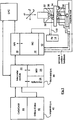
Figure 1 shows a first NC machine and its control which is suitable for implementing the invention; -
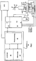
Figure 2 shows a second NC machine and its control suitable for implementing the invention; and -
Fig 3 shows a computer used for implementing the invention. - Referring to
Fig 1 , the NC machine is shown having a conventionalnumeric controller NC 10. The NC 10 runs programs based on G codes which are turned into movements of the machine byservos 36 controlled by amotion control system 12. Movements are in the x, y and z planes in this example. As well as cutting tools, ameasurement probe 30 can be mounted to thespindle 32 of the machine. Theprobe 30 is moved by the program around aworkpiece 34 and can transmit to areceiver 14data 16 relating to the deviations of itsstylus 38 relative to the main body portion of theprobe 30. This data can be used to determine workpiece size, geometry and surface finish and the like. An applicationsprogramming interface API 18 is used to load programs into theNC 10. TheAPI 18 is fed with programs from a software system operating within an ancillary processor 20 (known as a "front end p.c.") connected to the NC machine. The details of the operation of a system are contained in a patent applicationWO 03/012561 receiver 14 is directly connected to theNC 10 in this example. - The software system of the front end p.c. 20, in this instance, is being used to control what programs are being fed to the
NC 10. Decisions concerning the machining process are taken atInterpreter module 22 and are based on data obtained by probing routines run in the NC. - The NC programs can be generated in a high level language editor in the form of a CAD/
CAM software 44 running on a separate p.c. 40. Three other high level language editors are shown also: - i)
offline editor software 42 running resident also on the separate p.c. 40 ; - ii)
impromptu software 24 resident on the front end p.c. 20 and - iii) a manual
data input MDI 26 resident also on the front end p.c. 20. - The separate p.c. 40 runs also post processing software which converts high level language into low level language G codes suitable for the NC.
In operation an NC program may be generated, written or downloaded at the front end p.c. 20 e.g. by animpromptu editor 24 orMDI 26. The program could be generated, written or downloaded at the separate p.c. 40 e.g. at the CAD/CAM 44 orOffline editor 42 software. The system will control the program from wherever it comes and has the ability to make decisions based on feedback from the machine. The feedback will come via theAPI 18 and will include machine position data and probe data. - In this example the CAD/
CAM 44 program has been adapted by means of additional software so that, as well as high level instructions generated to perform the necessary cutting operations onworkpiece 34, the program can produce similar inspection instructions from data relating to the workpiece to be produced. These inspection instructions are embedded into the cutting instructions as comment fields. The whole program is post-processed in order to convert the instructions into G code commands which are readable by theNC 10. However, the comment fields are not so converted and remain as instructions which are ignored by theNC 10. - This composite program is loaded into the
Interpreter 22 and subsequently into theNC 10 via theAPI 18. This program, now resident in theNC 10, is referred to below as the main program. The instructions in the comment fields of the composite program are recognised by the Interpreter and are used to generate a program (a controlling program) which can control the main program. - As described in our earlier patent application
WO 03/012561 - Typical examples of such decisions made during the machining process of a squared component are:
- 1) Load the main program from the front end p.c. thereby generating a controlling program at the front end p.c. from the instructions in the comments fields of the main program;
- 2) Run the main program: load the workpiece into the machine and;
- 3) Load the cutting tool from the tool carousel and machine two sides of the square; replace the cutting tool into the carousel and pause the main program; load and run a probing routine (generated from instructions in comments fiends) to select a probe from the carousel and inspect the two sides and replace the probe in the carousel; pause the main program and await restart signal;
- 4) Send inspection data to the front end p.c. for processing (in parallel with the probing routine in this instance); make a logical decision on the basis of the results and update the controlling program if necessary;
- 5) If data relating to first two sides of the square is good then send restart signal and carry on machining, or;
- 6) If probing data indicates more machining required then download suitable path corrections and rewind the main program to send restart signal from step 2) or;
- 7) Probing data indicates too much material removed so scrap workpiece now and start restart cycle anew.
- The above example is very simplified. In practice far more movements and inspection steps are required. However the main program will pause until the system makes a decision, but the decision will be made while the main program runs in the
NC 10. So, the pause time will be very short or even zero. If repeat machining is required, the machining paths required could be calculated while theNC 10 runs other instructions to save time. - It can be seen that such a program will save machining time when compared to a conventional program that has simply a cutting program possibly followed by an inspection program.
- As well as the composite program described above, it is possible to produce an NC program which is readable wholly by the NC without unreadable high level instructions. Also it is possible to have also an NC program which is readable partially by the NC and which requires sub-programs (usually called macros) and which are called for by the NC program. The addition of comments unreadable by the NC program into the programs mentioned immediately above allows subsequent loading of such programs back into an editor of modification if required.
- Referring to
Fig 2 a modified control system is shown. Although similar to the system shown inFig 1 , no front end p.c. is present in this system. A separate p.c. 40 is used forprogram editors post-processing 46. Inspection instructions are converted into G codes during post-processing. In this case the high level instructions are not necessarily included in the G codes. All the instructions required for inspection can be included in the NC program. However the composite program is still generated and feature based generation of inspection routine is possible. - In each of the control systems illustrated in
Figs 1 and2 thereceiver 14 may also function as a transmitter for sending data to the probe e.g. in order to change its mode of operation. - All NC programs described above can in practice be produced using modified CAM software.
Fig 3 shows thecomputer 40 running the modified CAM software andscreen 48 which can be used to selectgeometric features 50 of a representation of theworkpiece 34 shown on thescreen 48. Alternatively any editing software which allows selection of geometric features can be used. - In use an operator will select a geometric feature using a screen pointer control e.g. "clicking" on a feature using a
mouse 49 and this will generate an inspection path forprobe 30. Additionally the operator can produce cutter paths based on the geometric features. The paths are turned into usable NC commands and/or high level language instructions at the post processing stage carried out after the selection of the geometric features. - Many variants other than those described are envisaged. For example Lhe configuration of hardware may be altered. A single controlling processor could be employed which could run software concurrently to replace some or all of the separate devices shown. More specifically the
NC 10 described could be replaced by any type of processor and the separate and front end p.c.s could likewise be any type of processing equipment. - Whilst using the front end p.c. for inspection purposes is described, use of the p.c. for other functions related to the machining process (but not necessarily inspection) are possible e.g. complex mathematics and analysis, modifying tool paths and the programs that define tool paths, producing error recovery actions, formatting printer output, saving results to an external file or database and driving ancillary equipment such as manipulation devices.
Claims (15)
- A method for producing a program for a machine tool, the method comprising the steps of:i) running a CAM program (44) containing data relating to a plurality of geometric features (50) of a workpiece (34), the CAM program producing pictures of the geometric features (50) on a computer screen (48);ii) receiving from an operator a selection of one of the pictures of the geometric features (50) on the computer screen (48), thereby selecting that geometric feature from the plurality of geometric features;iii) generating a measurement probe path for inspection of the selected geometric feature; andiv) providing a machine tool cutter path; characterised by:v) generating an integrated program containing both the machine tool cutter path and the generated measurement probe path for use with a motion control (12) of the machine tool to control movement of the machine tool.
- A method as claimed in claim 1 wherein the step of generating a measurement probe path includes at least one of the following:generating a path for the probe (30) to follow the surface of the workpiece; orgenerating a path for touching selected points at the workpiece surface.
- A method as claimed in claim 1 further including any of the steps of:selecting a path of the measurement probe (30) toward and away from the workpiece;selecting the speed of the measurement probe (30); orselecting the number of points on the surface of the workpiece to be inspected.
- A method as claimed in claim 1 further including the step of:generating a visualisation of the path of the measurement probe (30) with respect to the workpiece and showing the visualisation on a computer screen (48).
- A method as claimed in claim 1 wherein the CAM program (44) containing data relating to geometric features of the workpiece is an editing software program (42).
- A method as claimed in claim 1 wherein the geometric feature (50) selected is an unfinished workpiece feature and the measurement probe path is generated accordingly.
- A method as claimed in claim 1 further including the step of generating a machine tool cutter path.
- A method as claimed in claim 1 including generating an NC machine tool program including the step of:generating an NC program containing low level language commands for interpretation by a motion control (12) of an NC machine, and containing high level language instructions which are not interpretable by the motion control (12) of the NC machine.
- A method as claimed in claim 8 wherein the step of generating an NC program includes post processing a high level language program containing high level language instructions and converting only some of the high level language instructions into the said low level language commands.
- A method as claimed in claim 9 further including the step of:causing reading of the high level language instructions by ancillary software following the loading of the NC program into an NC controller (10).
- A method as claimed in claim 10 further including the step of:converting the high level language instructions into low level language commands at the ancillary software for use by the NC controller (10) when required.
- A method as claimed in claim 11 further including the step of:pausing the ancillary software to await feedback from the NC controller (10) and to convert the high level language instructions in a manner dependent on the feedback.
- A software program configured to perform a method according to any one of the preceding claims.
- Computer processing equipment (40) configured to perform a method according to any one of claims 1 to 12.
- A machine tool provided with computer processing equipment according to claim 14.
Applications Claiming Priority (2)
| Application Number | Priority Date | Filing Date | Title |
|---|---|---|---|
| GBGB0303270.3A GB0303270D0 (en) | 2003-02-13 | 2003-02-13 | A machine tool control process and apparatus therefor |
| EP04710926A EP1595186A2 (en) | 2003-02-13 | 2004-02-13 | Method for producing a measurement probe path on a numerically controlled coordinate measuring machine |
Related Parent Applications (2)
| Application Number | Title | Priority Date | Filing Date |
|---|---|---|---|
| EP04710926A Division EP1595186A2 (en) | 2003-02-13 | 2004-02-13 | Method for producing a measurement probe path on a numerically controlled coordinate measuring machine |
| EP04710926.9 Division | 2004-02-13 |
Publications (2)
| Publication Number | Publication Date |
|---|---|
| EP2270615A1 EP2270615A1 (en) | 2011-01-05 |
| EP2270615B1 true EP2270615B1 (en) | 2016-04-13 |
Family
ID=9952930
Family Applications (3)
| Application Number | Title | Priority Date | Filing Date |
|---|---|---|---|
| EP10011332.3A Expired - Lifetime EP2273332B1 (en) | 2003-02-13 | 2004-02-13 | A machine tool control process and apparatus therefor |
| EP10011920.5A Expired - Lifetime EP2270615B1 (en) | 2003-02-13 | 2004-02-13 | Method for producing a measurement probe path on a numerically controlled machine tool |
| EP04710926A Withdrawn EP1595186A2 (en) | 2003-02-13 | 2004-02-13 | Method for producing a measurement probe path on a numerically controlled coordinate measuring machine |
Family Applications Before (1)
| Application Number | Title | Priority Date | Filing Date |
|---|---|---|---|
| EP10011332.3A Expired - Lifetime EP2273332B1 (en) | 2003-02-13 | 2004-02-13 | A machine tool control process and apparatus therefor |
Family Applications After (1)
| Application Number | Title | Priority Date | Filing Date |
|---|---|---|---|
| EP04710926A Withdrawn EP1595186A2 (en) | 2003-02-13 | 2004-02-13 | Method for producing a measurement probe path on a numerically controlled coordinate measuring machine |
Country Status (6)
| Country | Link |
|---|---|
| US (1) | US9235205B2 (en) |
| EP (3) | EP2273332B1 (en) |
| JP (3) | JP4680176B2 (en) |
| CN (3) | CN1748187A (en) |
| GB (1) | GB0303270D0 (en) |
| WO (1) | WO2004072740A2 (en) |
Families Citing this family (44)
| Publication number | Priority date | Publication date | Assignee | Title |
|---|---|---|---|---|
| US8417370B2 (en) | 2003-10-17 | 2013-04-09 | Hexagon Metrology Ab | Apparatus and method for dimensional metrology |
| DE102004045933A1 (en) * | 2004-09-22 | 2006-03-30 | Siemens Ag | Method for operating an automation device or device for carrying out the method |
| DE102006034592A1 (en) | 2006-07-26 | 2008-01-31 | Kmw-Engineering Gmbh | Automated numerical control unit and process to finish the miter corners of plastic window frames |
| US20080161965A1 (en) * | 2006-12-27 | 2008-07-03 | Haines Luke D | Computer-aided manufacturing integrated machine probing |
| GB0707720D0 (en) | 2007-04-23 | 2007-05-30 | Renishaw Plc | Apparatus and method for controlling or programming a measurement routine |
| GB0716218D0 (en) | 2007-08-20 | 2007-09-26 | Renishaw Plc | Measurement path generation |
| US20090062950A1 (en) * | 2007-08-27 | 2009-03-05 | Ren An Information Technology Co., Ltd. | System and method for monitoring production of cnc machines |
| JP4653824B2 (en) * | 2008-07-29 | 2011-03-16 | ファナック株式会社 | A machine tool system that measures the shape of a measurement object using an on-machine measuring device |
| CN101995849B (en) * | 2009-08-24 | 2012-03-21 | 台达电子工业股份有限公司 | Path track point calculating device and method for numerical control system |
| JP5302165B2 (en) * | 2009-11-04 | 2013-10-02 | ファナック株式会社 | Numerical control device for controlling a machine tool equipped with a measuring device |
| US8352212B2 (en) | 2009-11-18 | 2013-01-08 | Hexagon Metrology, Inc. | Manipulable aid for dimensional metrology |
| DE102011115254A1 (en) * | 2011-09-27 | 2013-03-28 | Fritz Studer Ag | Machine tool and method for measuring a workpiece |
| US8833169B2 (en) * | 2011-12-09 | 2014-09-16 | General Electric Company | System and method for inspection of a part with dual multi-axis robotic devices |
| JP5906956B2 (en) * | 2012-06-20 | 2016-04-20 | 株式会社ミツトヨ | NC machine tool control method, control program, and control apparatus |
| CN104768706B (en) * | 2012-10-30 | 2017-05-17 | 株式会社牧野铣床制作所 | Processing program generation method and device |
| EP2796954B1 (en) | 2013-04-23 | 2015-11-25 | Siemens Aktiengesellschaft | Numerical controller with notification of a CAM system when the part program is changed |
| US9639083B2 (en) | 2013-12-18 | 2017-05-02 | Mitutoyo Corporation | System and method for programming workpiece feature inspection operations for a coordinate measuring machine |
| US20150220078A1 (en) * | 2014-02-03 | 2015-08-06 | Siemens Product Lifecycle Management Software Inc. | CAM and NC CODE INTEGRATION |
| WO2016083897A2 (en) | 2014-11-24 | 2016-06-02 | Kitov Systems Ltd. | Automated inspection |
| CN107438800A (en) | 2015-02-12 | 2017-12-05 | 格罗弗治公司 | The mobile material in laser processing procedure |
| US10509390B2 (en) | 2015-02-12 | 2019-12-17 | Glowforge Inc. | Safety and reliability guarantees for laser fabrication |
| CN104625876B (en) * | 2015-02-17 | 2018-02-09 | 中国船舶重工集团公司第七一一研究所 | Supercharger impeller blade machining process based on on-machine measurement |
| DE102015105436A1 (en) | 2015-04-09 | 2016-10-13 | Beckhoff Automation Gmbh | Translation module, processing module and control system |
| US10025289B2 (en) * | 2015-05-26 | 2018-07-17 | Pratt & Whitney Canada Corp. | System and method for automated part inspection |
| JP6514041B2 (en) | 2015-06-02 | 2019-05-15 | 株式会社ミツトヨ | Control method of shape measuring device |
| CN105094056A (en) * | 2015-06-29 | 2015-11-25 | 遵义宏港机械有限公司 | Numerical control milling machine automation coding method |
| CN104932431A (en) * | 2015-06-29 | 2015-09-23 | 遵义宏港机械有限公司 | Externally-added type numerically-controlled milling machine intelligent coding control method |
| CN106325214A (en) * | 2015-06-30 | 2017-01-11 | 遵义林棣科技发展有限公司 | Automatic coding method for numerical control lathe |
| JP2017030067A (en) * | 2015-07-30 | 2017-02-09 | ファナック株式会社 | Control device-added machining apparatus with machining time measuring function and on-machine measuring function |
| WO2018098396A1 (en) | 2016-11-25 | 2018-05-31 | Glowforge Inc. | Multi-user computer-numerically-controlled machine |
| WO2018098398A1 (en) | 2016-11-25 | 2018-05-31 | Glowforge Inc. | Preset optical components in a computer numerically controlled machine |
| CN110226137A (en) | 2016-11-25 | 2019-09-10 | 格罗弗治公司 | It is manufactured by image trace |
| WO2018098399A1 (en) | 2016-11-25 | 2018-05-31 | Glowforge Inc. | Controlled deceleration of moveable components in a computer numerically controlled machine |
| WO2018098393A1 (en) | 2016-11-25 | 2018-05-31 | Glowforge Inc. | Housing for computer-numerically-controlled machine |
| WO2018098397A1 (en) | 2016-11-25 | 2018-05-31 | Glowforge Inc. | Calibration of computer-numerically-controlled machine |
| WO2018098395A1 (en) | 2016-11-25 | 2018-05-31 | Glowforge Inc. | Improved engraving in a computer numerically controlled machine |
| JP6840585B2 (en) * | 2017-03-21 | 2021-03-10 | 株式会社ミツトヨ | Measurement system, measurement program and control method |
| CN107942948B (en) * | 2017-12-21 | 2020-10-27 | 苏州谷夫道自动化科技有限公司 | Method for graphically editing detection and processing programs of probe system |
| EP3671381A1 (en) * | 2018-12-20 | 2020-06-24 | Etxe-Tar, S.A. | Methods and systems for operating a machine in a manufacturing process |
| CN111045385A (en) * | 2019-12-26 | 2020-04-21 | 北京工业大学 | Error modeling and analyzing method for machine tool special for machining cambered surface cam |
| US11740608B2 (en) | 2020-12-24 | 2023-08-29 | Glowforge, Inc | Computer numerically controlled fabrication using projected information |
| US11698622B2 (en) | 2021-03-09 | 2023-07-11 | Glowforge Inc. | Previews for computer numerically controlled fabrication |
| JP7157886B1 (en) | 2022-02-14 | 2022-10-20 | Dmg森精機株式会社 | Information processing equipment, machine tools and information processing programs |
| CN116909206B (en) * | 2023-09-11 | 2023-12-22 | 上海泛腾半导体技术有限公司 | Embedded PLC motion control system |
Citations (1)
| Publication number | Priority date | Publication date | Assignee | Title |
|---|---|---|---|---|
| US4918627A (en) * | 1986-08-04 | 1990-04-17 | Fmc Corporation | Computer integrated gaging system |
Family Cites Families (38)
| Publication number | Priority date | Publication date | Assignee | Title |
|---|---|---|---|---|
| JPS59172009A (en) | 1983-03-22 | 1984-09-28 | Mitsubishi Electric Corp | Numerical controller |
| JPS59172008A (en) | 1983-03-22 | 1984-09-28 | Mitsubishi Electric Corp | Numerical controller |
| JPS6149209A (en) | 1984-08-17 | 1986-03-11 | Fanuc Ltd | Program execution system of numerical controller |
| JPS62152005A (en) * | 1985-12-25 | 1987-07-07 | Fanuc Ltd | Generating method for sequence program |
| JPS62198906A (en) | 1986-02-27 | 1987-09-02 | Mitsubishi Electric Corp | Check method for working program of numerical controller |
| JPS62210508A (en) | 1986-03-12 | 1987-09-16 | Mitsubishi Electric Corp | Numerical controller |
| JPS63184109A (en) | 1987-01-27 | 1988-07-29 | Mitsubishi Electric Corp | Numerical controller |
| GB2202659B (en) * | 1987-02-23 | 1991-07-17 | Mitutoyo Corp | Coordinate measuring instrument and method of generating pattern data concerning shape of work to be measured |
| JPH0827648B2 (en) | 1987-06-22 | 1996-03-21 | 株式会社日立製作所 | NC part program generator |
| JPH01100604A (en) | 1987-10-14 | 1989-04-18 | Fanuc Ltd | Programmable controller and its performing system |
| JPH01296305A (en) | 1988-05-25 | 1989-11-29 | Enshu Ltd | Method for modifying nc program by using set-up information |
| JPH01311372A (en) | 1988-06-10 | 1989-12-15 | Fanuc Ltd | Method for defining working shape |
| JPH03158908A (en) | 1989-11-17 | 1991-07-08 | Fanuc Ltd | Automatic programming system in compound working machine |
| JPH03176703A (en) * | 1989-12-05 | 1991-07-31 | Yoshiaki Kakino | Numerical controller |
| JP2792764B2 (en) | 1991-07-29 | 1998-09-03 | オークマ株式会社 | Numerical control data editing device |
| JPH0592349A (en) | 1991-09-27 | 1993-04-16 | Mitsubishi Heavy Ind Ltd | Numerically controlled device |
| JPH05158523A (en) | 1991-12-03 | 1993-06-25 | Murata Mach Ltd | Cad/cam data input system |
| JP3701317B2 (en) | 1992-04-28 | 2005-09-28 | 日本フイルコン株式会社 | A device that creates operational data for the machine |
| JPH06231215A (en) | 1993-02-03 | 1994-08-19 | Mitsubishi Electric Corp | Sheet metal cad/cam system |
| JPH079302A (en) | 1993-06-22 | 1995-01-13 | Enshu Ltd | Single item machining method of machining center or the like |
| DE4342660A1 (en) | 1993-12-14 | 1995-06-22 | Siemens Ag | Engineering machine programmed drive device |
| JPH07227738A (en) | 1994-02-21 | 1995-08-29 | Komori Seiki:Kk | Character engraving device using general purpose type numerically controlled machine |
| JPH08272648A (en) * | 1994-12-29 | 1996-10-18 | Hitachi Ltd | Method for automatically generating debugging command file and device for automatically regenerating break point in debugging command file |
| GB9600854D0 (en) | 1996-01-16 | 1996-03-20 | British Telecomm | Distributed processing |
| JPH09274511A (en) | 1996-04-04 | 1997-10-21 | Yokogawa Electric Corp | Sequence controller |
| EP0879674B1 (en) * | 1996-11-07 | 2003-04-02 | Mitutoyo Corporation | Generation of measurement program in nc machining and machining management based on the measurement program |
| DE19707107A1 (en) * | 1997-02-22 | 1998-09-10 | Bosch Gmbh Robert | Device for programming a PLC |
| US6075981A (en) * | 1997-10-29 | 2000-06-13 | Ericsson, Inc. | Method for responding to DCCH pointers |
| JPH11143511A (en) * | 1997-11-04 | 1999-05-28 | Fanuc Ltd | Numerical controller |
| US6314557B1 (en) * | 1998-12-14 | 2001-11-06 | Infineon Technologies Development Center Tel Aviv Ltd | Hybrid computer programming environment |
| JP3093192B2 (en) | 1998-12-21 | 2000-10-03 | 株式会社国興 | Work processing apparatus and computer-readable recording medium |
| JP2000207004A (en) | 1999-01-19 | 2000-07-28 | Yukiwa Seiko Inc | Nc control system |
| US6671571B1 (en) * | 1999-07-05 | 2003-12-30 | Mitutoyo Corporation | Method for NC- programming and system for NC- machining |
| CA2408335C (en) | 2000-05-16 | 2006-08-22 | Brigham Young University | Method and system for controlling a machine tool with direct transfer of machining data |
| DE10108688B4 (en) | 2001-02-23 | 2013-01-31 | Carl Zeiss Industrielle Messtechnik Gmbh | measuring device |
| GB0118492D0 (en) | 2001-07-30 | 2001-09-19 | Renishaw Plc | A machine tool control process and apparatus therfor |
| AU2002357737A1 (en) * | 2001-11-16 | 2003-06-10 | Faro Technologies, Inc. | Method and system for assisting a user taking measurements using a coordinate measurement machine |
| US6912446B2 (en) * | 2002-10-23 | 2005-06-28 | General Electric Company | Systems and methods for automated sensing and machining for repairing airfoils of blades |
-
2003
- 2003-02-13 GB GBGB0303270.3A patent/GB0303270D0/en not_active Ceased
-
2004
- 2004-02-13 EP EP10011332.3A patent/EP2273332B1/en not_active Expired - Lifetime
- 2004-02-13 CN CNA2004800039792A patent/CN1748187A/en active Pending
- 2004-02-13 CN CN2012101227371A patent/CN102637016A/en active Pending
- 2004-02-13 EP EP10011920.5A patent/EP2270615B1/en not_active Expired - Lifetime
- 2004-02-13 CN CN200810182729XA patent/CN101470430B/en not_active Expired - Fee Related
- 2004-02-13 US US10/545,077 patent/US9235205B2/en active Active
- 2004-02-13 EP EP04710926A patent/EP1595186A2/en not_active Withdrawn
- 2004-02-13 WO PCT/GB2004/000585 patent/WO2004072740A2/en active Application Filing
- 2004-02-13 JP JP2006502276A patent/JP4680176B2/en not_active Expired - Fee Related
-
2008
- 2008-02-06 JP JP2008026953A patent/JP5000543B2/en not_active Expired - Fee Related
-
2010
- 2010-12-20 JP JP2010283647A patent/JP5819061B2/en not_active Expired - Lifetime
Patent Citations (1)
| Publication number | Priority date | Publication date | Assignee | Title |
|---|---|---|---|---|
| US4918627A (en) * | 1986-08-04 | 1990-04-17 | Fmc Corporation | Computer integrated gaging system |
Also Published As
| Publication number | Publication date |
|---|---|
| WO2004072740A2 (en) | 2004-08-26 |
| EP1595186A2 (en) | 2005-11-16 |
| WO2004072740A3 (en) | 2004-11-04 |
| CN102637016A (en) | 2012-08-15 |
| GB0303270D0 (en) | 2003-03-19 |
| CN101470430B (en) | 2012-07-04 |
| EP2270615A1 (en) | 2011-01-05 |
| JP2008165821A (en) | 2008-07-17 |
| CN1748187A (en) | 2006-03-15 |
| US9235205B2 (en) | 2016-01-12 |
| EP2273332B1 (en) | 2015-08-26 |
| JP5819061B2 (en) | 2015-11-18 |
| EP2273332A1 (en) | 2011-01-12 |
| US20070005178A1 (en) | 2007-01-04 |
| JP2006517472A (en) | 2006-07-27 |
| JP4680176B2 (en) | 2011-05-11 |
| JP2011096276A (en) | 2011-05-12 |
| JP5000543B2 (en) | 2012-08-15 |
| CN101470430A (en) | 2009-07-01 |
Similar Documents
| Publication | Publication Date | Title |
|---|---|---|
| EP2270615B1 (en) | Method for producing a measurement probe path on a numerically controlled machine tool | |
| EP1769296B1 (en) | Method for generating a cnc machine tool control program | |
| EP2417498B1 (en) | Method for automatically partitioning a part program into fundamental operations | |
| CN1722034A (en) | Numerical controller | |
| US6591156B1 (en) | Method and apparatus for providing numerical control information | |
| CN105807719A (en) | Method and device for composite machining | |
| EP3088978B1 (en) | Control apparatus for machine tool | |
| US9429928B2 (en) | Control method, non-transitory computer readable medium and controller of numerical control machine tool | |
| CN106886197B (en) | Method for controlling machine to implement machining, device and application thereof | |
| Yusof et al. | New interpretation module for open architecture control based CNC systems | |
| CN106886195B (en) | Machining control method, device and application thereof | |
| WO2017101700A1 (en) | Computer aided manufacturing method, device and system in direct communication with numerical control system | |
| JP2017157194A (en) | Numerical controller for machine tool | |
| Schmid et al. | Validation of machining operations by a Virtual Numerical Controller Kernel based simulation | |
| JP7177905B1 (en) | Information processing equipment | |
| KR100401635B1 (en) | Method for check grammer a manufacture programming of numerical control type machine tool | |
| Čuboňová | Creation of software for the transformation of Step-Nc Data | |
| Yusof et al. | Comparison of Communication with the CNC Systems | |
| Lorini et al. | A Milling System with Robot Resources | |
| JPH06161534A (en) | Cutter pass inspecting method |
Legal Events
| Date | Code | Title | Description |
|---|---|---|---|
| PUAI | Public reference made under article 153(3) epc to a published international application that has entered the european phase |
Free format text: ORIGINAL CODE: 0009012 |
|
| AC | Divisional application: reference to earlier application |
Ref document number: 1595186 Country of ref document: EP Kind code of ref document: P |
|
| AK | Designated contracting states |
Kind code of ref document: A1 Designated state(s): AT BE BG CH CY CZ DE DK EE ES FI FR GB GR HU IE IT LI LU MC NL PT RO SE SI SK TR |
|
| 17P | Request for examination filed |
Effective date: 20110704 |
|
| 17Q | First examination report despatched |
Effective date: 20110811 |
|
| GRAP | Despatch of communication of intention to grant a patent |
Free format text: ORIGINAL CODE: EPIDOSNIGR1 |
|
| INTG | Intention to grant announced |
Effective date: 20151005 |
|
| RIN1 | Information on inventor provided before grant (corrected) |
Inventor name: OULD, JOHN CHARLES Inventor name: PRESTIDGE, TIM |
|
| GRAS | Grant fee paid |
Free format text: ORIGINAL CODE: EPIDOSNIGR3 |
|
| GRAA | (expected) grant |
Free format text: ORIGINAL CODE: 0009210 |
|
| AC | Divisional application: reference to earlier application |
Ref document number: 1595186 Country of ref document: EP Kind code of ref document: P |
|
| AK | Designated contracting states |
Kind code of ref document: B1 Designated state(s): AT BE BG CH CY CZ DE DK EE ES FI FR GB GR HU IE IT LI LU MC NL PT RO SE SI SK TR |
|
| REG | Reference to a national code |
Ref country code: GB Ref legal event code: FG4D |
|
| REG | Reference to a national code |
Ref country code: AT Ref legal event code: REF Ref document number: 790775 Country of ref document: AT Kind code of ref document: T Effective date: 20160415 Ref country code: CH Ref legal event code: EP |
|
| REG | Reference to a national code |
Ref country code: IE Ref legal event code: FG4D |
|
| REG | Reference to a national code |
Ref country code: DE Ref legal event code: R096 Ref document number: 602004049088 Country of ref document: DE |
|
| REG | Reference to a national code |
Ref country code: AT Ref legal event code: MK05 Ref document number: 790775 Country of ref document: AT Kind code of ref document: T Effective date: 20160413 |
|
| REG | Reference to a national code |
Ref country code: NL Ref legal event code: MP Effective date: 20160413 |
|
| PG25 | Lapsed in a contracting state [announced via postgrant information from national office to epo] |
Ref country code: NL Free format text: LAPSE BECAUSE OF FAILURE TO SUBMIT A TRANSLATION OF THE DESCRIPTION OR TO PAY THE FEE WITHIN THE PRESCRIBED TIME-LIMIT Effective date: 20160413 Ref country code: FI Free format text: LAPSE BECAUSE OF FAILURE TO SUBMIT A TRANSLATION OF THE DESCRIPTION OR TO PAY THE FEE WITHIN THE PRESCRIBED TIME-LIMIT Effective date: 20160413 |
|
| PG25 | Lapsed in a contracting state [announced via postgrant information from national office to epo] |
Ref country code: PT Free format text: LAPSE BECAUSE OF FAILURE TO SUBMIT A TRANSLATION OF THE DESCRIPTION OR TO PAY THE FEE WITHIN THE PRESCRIBED TIME-LIMIT Effective date: 20160816 Ref country code: SE Free format text: LAPSE BECAUSE OF FAILURE TO SUBMIT A TRANSLATION OF THE DESCRIPTION OR TO PAY THE FEE WITHIN THE PRESCRIBED TIME-LIMIT Effective date: 20160413 Ref country code: GR Free format text: LAPSE BECAUSE OF FAILURE TO SUBMIT A TRANSLATION OF THE DESCRIPTION OR TO PAY THE FEE WITHIN THE PRESCRIBED TIME-LIMIT Effective date: 20160714 Ref country code: AT Free format text: LAPSE BECAUSE OF FAILURE TO SUBMIT A TRANSLATION OF THE DESCRIPTION OR TO PAY THE FEE WITHIN THE PRESCRIBED TIME-LIMIT Effective date: 20160413 Ref country code: ES Free format text: LAPSE BECAUSE OF FAILURE TO SUBMIT A TRANSLATION OF THE DESCRIPTION OR TO PAY THE FEE WITHIN THE PRESCRIBED TIME-LIMIT Effective date: 20160413 |
|
| PG25 | Lapsed in a contracting state [announced via postgrant information from national office to epo] |
Ref country code: BE Free format text: LAPSE BECAUSE OF FAILURE TO SUBMIT A TRANSLATION OF THE DESCRIPTION OR TO PAY THE FEE WITHIN THE PRESCRIBED TIME-LIMIT Effective date: 20160413 |
|
| REG | Reference to a national code |
Ref country code: DE Ref legal event code: R097 Ref document number: 602004049088 Country of ref document: DE |
|
| PG25 | Lapsed in a contracting state [announced via postgrant information from national office to epo] |
Ref country code: SK Free format text: LAPSE BECAUSE OF FAILURE TO SUBMIT A TRANSLATION OF THE DESCRIPTION OR TO PAY THE FEE WITHIN THE PRESCRIBED TIME-LIMIT Effective date: 20160413 Ref country code: EE Free format text: LAPSE BECAUSE OF FAILURE TO SUBMIT A TRANSLATION OF THE DESCRIPTION OR TO PAY THE FEE WITHIN THE PRESCRIBED TIME-LIMIT Effective date: 20160413 Ref country code: DK Free format text: LAPSE BECAUSE OF FAILURE TO SUBMIT A TRANSLATION OF THE DESCRIPTION OR TO PAY THE FEE WITHIN THE PRESCRIBED TIME-LIMIT Effective date: 20160413 Ref country code: RO Free format text: LAPSE BECAUSE OF FAILURE TO SUBMIT A TRANSLATION OF THE DESCRIPTION OR TO PAY THE FEE WITHIN THE PRESCRIBED TIME-LIMIT Effective date: 20160413 Ref country code: CZ Free format text: LAPSE BECAUSE OF FAILURE TO SUBMIT A TRANSLATION OF THE DESCRIPTION OR TO PAY THE FEE WITHIN THE PRESCRIBED TIME-LIMIT Effective date: 20160413 |
|
| PLBE | No opposition filed within time limit |
Free format text: ORIGINAL CODE: 0009261 |
|
| STAA | Information on the status of an ep patent application or granted ep patent |
Free format text: STATUS: NO OPPOSITION FILED WITHIN TIME LIMIT |
|
| 26N | No opposition filed |
Effective date: 20170116 |
|
| PG25 | Lapsed in a contracting state [announced via postgrant information from national office to epo] |
Ref country code: SI Free format text: LAPSE BECAUSE OF FAILURE TO SUBMIT A TRANSLATION OF THE DESCRIPTION OR TO PAY THE FEE WITHIN THE PRESCRIBED TIME-LIMIT Effective date: 20160413 |
|
| PG25 | Lapsed in a contracting state [announced via postgrant information from national office to epo] |
Ref country code: MC Free format text: LAPSE BECAUSE OF FAILURE TO SUBMIT A TRANSLATION OF THE DESCRIPTION OR TO PAY THE FEE WITHIN THE PRESCRIBED TIME-LIMIT Effective date: 20160413 |
|
| REG | Reference to a national code |
Ref country code: CH Ref legal event code: PL |
|
| PG25 | Lapsed in a contracting state [announced via postgrant information from national office to epo] |
Ref country code: CH Free format text: LAPSE BECAUSE OF NON-PAYMENT OF DUE FEES Effective date: 20170228 Ref country code: LI Free format text: LAPSE BECAUSE OF NON-PAYMENT OF DUE FEES Effective date: 20170228 |
|
| REG | Reference to a national code |
Ref country code: IE Ref legal event code: MM4A |
|
| REG | Reference to a national code |
Ref country code: FR Ref legal event code: ST Effective date: 20171031 |
|
| PG25 | Lapsed in a contracting state [announced via postgrant information from national office to epo] |
Ref country code: LU Free format text: LAPSE BECAUSE OF NON-PAYMENT OF DUE FEES Effective date: 20170213 |
|
| PG25 | Lapsed in a contracting state [announced via postgrant information from national office to epo] |
Ref country code: FR Free format text: LAPSE BECAUSE OF NON-PAYMENT OF DUE FEES Effective date: 20170228 |
|
| PG25 | Lapsed in a contracting state [announced via postgrant information from national office to epo] |
Ref country code: IE Free format text: LAPSE BECAUSE OF NON-PAYMENT OF DUE FEES Effective date: 20170213 |
|
| PG25 | Lapsed in a contracting state [announced via postgrant information from national office to epo] |
Ref country code: HU Free format text: LAPSE BECAUSE OF FAILURE TO SUBMIT A TRANSLATION OF THE DESCRIPTION OR TO PAY THE FEE WITHIN THE PRESCRIBED TIME-LIMIT; INVALID AB INITIO Effective date: 20040213 |
|
| PG25 | Lapsed in a contracting state [announced via postgrant information from national office to epo] |
Ref country code: BG Free format text: LAPSE BECAUSE OF FAILURE TO SUBMIT A TRANSLATION OF THE DESCRIPTION OR TO PAY THE FEE WITHIN THE PRESCRIBED TIME-LIMIT Effective date: 20160413 |
|
| PG25 | Lapsed in a contracting state [announced via postgrant information from national office to epo] |
Ref country code: CY Free format text: LAPSE BECAUSE OF NON-PAYMENT OF DUE FEES Effective date: 20160413 |
|
| PG25 | Lapsed in a contracting state [announced via postgrant information from national office to epo] |
Ref country code: TR Free format text: LAPSE BECAUSE OF FAILURE TO SUBMIT A TRANSLATION OF THE DESCRIPTION OR TO PAY THE FEE WITHIN THE PRESCRIBED TIME-LIMIT Effective date: 20160413 |
|
| PGFP | Annual fee paid to national office [announced via postgrant information from national office to epo] |
Ref country code: GB Payment date: 20220222 Year of fee payment: 19 |
|
| PGFP | Annual fee paid to national office [announced via postgrant information from national office to epo] |
Ref country code: IT Payment date: 20220221 Year of fee payment: 19 |
|
| PGFP | Annual fee paid to national office [announced via postgrant information from national office to epo] |
Ref country code: DE Payment date: 20230227 Year of fee payment: 20 |
|
| P01 | Opt-out of the competence of the unified patent court (upc) registered |
Effective date: 20230602 |
|
| GBPC | Gb: european patent ceased through non-payment of renewal fee |
Effective date: 20230213 |
|
| PG25 | Lapsed in a contracting state [announced via postgrant information from national office to epo] |
Ref country code: GB Free format text: LAPSE BECAUSE OF NON-PAYMENT OF DUE FEES Effective date: 20230213 |
|
| PG25 | Lapsed in a contracting state [announced via postgrant information from national office to epo] |
Ref country code: IT Free format text: LAPSE BECAUSE OF NON-PAYMENT OF DUE FEES Effective date: 20230213 Ref country code: GB Free format text: LAPSE BECAUSE OF NON-PAYMENT OF DUE FEES Effective date: 20230213 |
|
| REG | Reference to a national code |
Ref country code: DE Ref legal event code: R071 Ref document number: 602004049088 Country of ref document: DE |