EP2270825B1 - Keypad and keypad assembly - Google Patents
Keypad and keypad assembly Download PDFInfo
- Publication number
- EP2270825B1 EP2270825B1 EP10184445A EP10184445A EP2270825B1 EP 2270825 B1 EP2270825 B1 EP 2270825B1 EP 10184445 A EP10184445 A EP 10184445A EP 10184445 A EP10184445 A EP 10184445A EP 2270825 B1 EP2270825 B1 EP 2270825B1
- Authority
- EP
- European Patent Office
- Prior art keywords
- light guide
- guide panel
- keypad
- light
- film
- Prior art date
- Legal status (The legal status is an assumption and is not a legal conclusion. Google has not performed a legal analysis and makes no representation as to the accuracy of the status listed.)
- Active
Links
- 239000000463 material Substances 0.000 claims description 7
- 238000003825 pressing Methods 0.000 claims description 3
- 230000001902 propagating effect Effects 0.000 claims description 3
- 238000009792 diffusion process Methods 0.000 description 6
- 238000005286 illumination Methods 0.000 description 5
- 238000009826 distribution Methods 0.000 description 3
- 229920001971 elastomer Polymers 0.000 description 3
- 239000000806 elastomer Substances 0.000 description 3
- 230000002093 peripheral effect Effects 0.000 description 3
- 238000002834 transmittance Methods 0.000 description 3
- ICOAEPDGFWLUTI-UHFFFAOYSA-N 2,2',4,4',6,6'-hexachlorobiphenyl Chemical compound ClC1=CC(Cl)=CC(Cl)=C1C1=C(Cl)C=C(Cl)C=C1Cl ICOAEPDGFWLUTI-UHFFFAOYSA-N 0.000 description 2
- -1 acryl Chemical group 0.000 description 2
- 239000003795 chemical substances by application Substances 0.000 description 2
- 238000004519 manufacturing process Methods 0.000 description 2
- 230000003287 optical effect Effects 0.000 description 2
- 229920000515 polycarbonate Polymers 0.000 description 2
- 239000004417 polycarbonate Substances 0.000 description 2
- 229920001296 polysiloxane Polymers 0.000 description 2
- 229920002635 polyurethane Polymers 0.000 description 2
- 239000004814 polyurethane Substances 0.000 description 2
- 239000011347 resin Substances 0.000 description 2
- 229920005989 resin Polymers 0.000 description 2
- 238000010276 construction Methods 0.000 description 1
- 230000000694 effects Effects 0.000 description 1
- 238000001746 injection moulding Methods 0.000 description 1
- 230000002452 interceptive effect Effects 0.000 description 1
- 238000006748 scratching Methods 0.000 description 1
- 230000002393 scratching effect Effects 0.000 description 1
- 239000007787 solid Substances 0.000 description 1
Images

Classifications
-
- H—ELECTRICITY
- H01—ELECTRIC ELEMENTS
- H01H—ELECTRIC SWITCHES; RELAYS; SELECTORS; EMERGENCY PROTECTIVE DEVICES
- H01H13/00—Switches having rectilinearly-movable operating part or parts adapted for pushing or pulling in one direction only, e.g. push-button switch
- H01H13/70—Switches having rectilinearly-movable operating part or parts adapted for pushing or pulling in one direction only, e.g. push-button switch having a plurality of operating members associated with different sets of contacts, e.g. keyboard
- H01H13/83—Switches having rectilinearly-movable operating part or parts adapted for pushing or pulling in one direction only, e.g. push-button switch having a plurality of operating members associated with different sets of contacts, e.g. keyboard characterised by legends, e.g. Braille, liquid crystal displays, light emitting or optical elements
-
- H—ELECTRICITY
- H01—ELECTRIC ELEMENTS
- H01H—ELECTRIC SWITCHES; RELAYS; SELECTORS; EMERGENCY PROTECTIVE DEVICES
- H01H2209/00—Layers
- H01H2209/068—Properties of the membrane
- H01H2209/074—Properties of the membrane elastomeric
-
- H—ELECTRICITY
- H01—ELECTRIC ELEMENTS
- H01H—ELECTRIC SWITCHES; RELAYS; SELECTORS; EMERGENCY PROTECTIVE DEVICES
- H01H2209/00—Layers
- H01H2209/068—Properties of the membrane
- H01H2209/082—Properties of the membrane transparent
-
- H—ELECTRICITY
- H01—ELECTRIC ELEMENTS
- H01H—ELECTRIC SWITCHES; RELAYS; SELECTORS; EMERGENCY PROTECTIVE DEVICES
- H01H2215/00—Tactile feedback
- H01H2215/004—Collapsible dome or bubble
- H01H2215/01—Part of spacer
-
- H—ELECTRICITY
- H01—ELECTRIC ELEMENTS
- H01H—ELECTRIC SWITCHES; RELAYS; SELECTORS; EMERGENCY PROTECTIVE DEVICES
- H01H2219/00—Legends
- H01H2219/036—Light emitting elements
- H01H2219/044—Edge lighting of layer
-
- H—ELECTRICITY
- H01—ELECTRIC ELEMENTS
- H01H—ELECTRIC SWITCHES; RELAYS; SELECTORS; EMERGENCY PROTECTIVE DEVICES
- H01H2219/00—Legends
- H01H2219/054—Optical elements
- H01H2219/056—Diffuser; Uneven surface
-
- H—ELECTRICITY
- H01—ELECTRIC ELEMENTS
- H01H—ELECTRIC SWITCHES; RELAYS; SELECTORS; EMERGENCY PROTECTIVE DEVICES
- H01H2219/00—Legends
- H01H2219/054—Optical elements
- H01H2219/06—Reflector
-
- H—ELECTRICITY
- H01—ELECTRIC ELEMENTS
- H01H—ELECTRIC SWITCHES; RELAYS; SELECTORS; EMERGENCY PROTECTIVE DEVICES
- H01H2219/00—Legends
- H01H2219/054—Optical elements
- H01H2219/062—Light conductor
-
- H—ELECTRICITY
- H01—ELECTRIC ELEMENTS
- H01H—ELECTRIC SWITCHES; RELAYS; SELECTORS; EMERGENCY PROTECTIVE DEVICES
- H01H2221/00—Actuators
- H01H2221/002—Actuators integral with membrane
-
- H—ELECTRICITY
- H01—ELECTRIC ELEMENTS
- H01H—ELECTRIC SWITCHES; RELAYS; SELECTORS; EMERGENCY PROTECTIVE DEVICES
- H01H2221/00—Actuators
- H01H2221/07—Actuators transparent
Definitions
- the present invention relates to a keypad used in a portable terminal, and more particularly to a keypad and a keypad assembly having a light guide panel.
- a keypad used in a portable terminal typically includes an elastic pad plate, a plurality of key buttons formed on the upper surface of the elastic pad with characters printed on the upper surface thereof, respectively, and a plurality of protrusions (or actuators) formed on the lower surface of the elastic pad.
- This type of portable terminal normally has about 15-20 light emitting devices serving as a back light of the keypad.
- An example of illuminated keypad is disclosed in US-A-5569367 .
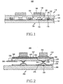
- FIG 1 is a sectional view showing a keypad assembly according to the prior art.
- the keypad assembly 100 includes a keypad 110, a switch board 150, and a plurality of light emitting diodes(LEDs) 170.
- LEDs light emitting diodes
- the keypad 110 includes an elastic pad 120 having the shape of a plate, a plurality of key buttons 140 formed on the upper surface 122 of the elastic pad 120 with characters, numbers, etc., printed on the upper surface thereof, respectively, and a plurality of protrusions 130 formed on the lower surface 124 of the elastic pad 120, which is opposite to the upper surface 122 of the elastic pad 120.
- Each of the protrusions 130 is aligned with the center portion of the corresponding key button 140.
- the elastic pad 120 has a plurality of grooves 126 formed on the lower surface 124 thereof. The grooves 126 are positioned around the respective protrusions 130 to prevent the LEDs 170 from interfering with the protrusions 130.
- the switch board 150 has a plate-shaped PCB(Printed Circuit Board) 155 and a plurality of switches 160 formed on the upper surface of the PCB 155 facing the keypad 110.
- Each switch 160 is comprised of a conductive contact member 162 and a conductive dome 164 covering the contact member 162 completely.
- the plurality of LEDs 170 are mounted on the upper surface of the PCB 155, and each LED 170 is positioned to be covered by the corresponding groove 126 of the elastic pad 120.
- the portion of the keypad 110 positioned beneath the pressed key button 140 deforms towards the switch board 150.
- one of the protrusions 130 corresponding to the deformed portion presses the corresponding dome 164, thus providing an electrical contact with the corresponding contact member 162.
- the LEDs 170 Due to the operation of the switches 160 in the vicinity, the LEDs 170 must not be positioned beneath the corresponding key buttons 140. Light outputted from the respective LEDs 170 passes through the elastic pad 120 and illuminates the respective key buttons 140 at an oblique angle. As a result, the key buttons 140 are dimly illuminated in a non-uniformly fashion. In particular, the center of each key button 140 looks darker, and the periphery thereof looks brighter. If more LEDs are installed to enhance an uniform illumination of the key buttons 140, power consumption and manufacturing cost increase.
- the present invention has been made to solve the above-mentioned problems occurring in the prior art and provides additional advantages, by providing a keypad and a keypad assembly capable of realizing high and uniform brightness, while consuming less power and costing less.
- a keypad including a light guide panel, the interior of which light propagates through; a film positioned on the upper surface of the light guide panel and having at least one key button positioned on the upper surface thereof; and at least one reflective pattern fixedly positioned with respect to the light guide panel to reflect a part of the light, which propagates through the interior of the light guide panel, towards the key button.
- a keypad assembly including a keypad having a light guide panel, the interior of which light propagates through, and a film positioned on the upper surface of the light guide panel with at least one key button positioned on the upper surface of the film and a switch board having at least one switch formed on its upper surface, which faces the keypad, wherein as the key button is pressed, the portion of the keypad deformed towards the switch board presses the switch.
- a portable terminal including a switch board having at least one switch positioned on the upper surface thereof; a keypad having a light guide panel with upper, lower, and lateral surfaces; and at least one light emitting device positioned adjacent to at least one of the lateral surfaces of the light guide panel, wherein the keypad includes a film positioned on the upper surface of the light guide panel and having at least one key button positioned on the upper surface thereof and at least one reflective pattern locally formed on the light guide panel to reflect a part of light, which propagates through the interior of the light guide panel, towards the key button.
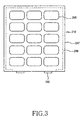
- FIG 2 is a sectional view showing a keypad assembly according to a first embodiment of the present invention
- FIG. 3 is a top view briefly showing a part of the keypad assembly.
- the keypad assembly 200 includes a keypad 210, a switch board 250 facing the keypad 210, at least one light emitting device 290, and a second PCB 280.
- the keypad 210 includes a light guide panel 220, a film 247, a plurality of key buttons 245, a plurality of protrusions 240, and a plurality of reflective patterns 230 (indicated by solid triangles).
- the light guide panel 220 guides light coupled to the interior thereof
- the coupled light propagates from a lateral surface of the light guide panel 220 to the opposite lateral surface thereof.
- the light guide panel 220 may have any shape, such as a square.
- the light coupled to the interior of the light guide panel 220 propagates into the light guide panel 220 due to a total reflection at the interface between the light guide panel 220 and the external air layer.
- the light guide panel 220 has elasticity so that the key buttons 245, when pressed, can return to the original position. That is, the light guide panel 220 has self-restoration properties so that it can restore the original shape after deformation and, after the key buttons 245 are operated, returns them to the original position.
- Conventional light guide panels are manufactured by injection-molding process using polycarbonate or acryl-based resin which has a high transmittance for visible rays. They have low elastic modulus, poor elastic restoration properties, and high hardness. This makes it difficult to obtain a good click feel when pressing key buttons. Also, when a key button is pressed, adjacent key buttons may be erroneously operated together (interference among key buttons). Further, permanent deformation may easily occur after repeated operation.
- the light guide panel 220 is made of a highly transparent elastomer material, preferably polyurethane or silicone, which has low hardness, high elastic modulus, excellent elastic restoration properties, and high optical transmittance, in order to provide a good click feel, suppress interference among key buttons 245, and avoid permanent deformation even after repeated operation.
- a highly transparent elastomer material preferably polyurethane or silicone, which has low hardness, high elastic modulus, excellent elastic restoration properties, and high optical transmittance, in order to provide a good click feel, suppress interference among key buttons 245, and avoid permanent deformation even after repeated operation.
- the film 247 is disposed on the upper surface of the light guide panel 220, and it has a plurality of key buttons 245 positioned on the upper surface thereof.
- the periphery of the film 247 is attached to the periphery of the light guide panel 220 using an adhesion member 249 to bond and maintain an upper air layer between the film 247 and the light guide panel 220.
- the adhesion member 249 is preferably positioned on the periphery of the light guide panel 220 as the rest of light which is not used to illuminate the key buttons 245 reaches the periphery of the light guide panel 220.
- the film 247 preferably has such surface properties that it is not attached to the upper surface of the light guide panel 220, because, if the center of the film 247 having the key buttons positioned thereon is attached to the upper surface of the light guide panel 220, no air layer can be maintained between the light guide panel 220 and the film 247.
- the surface of the film 247 may be roughened or coated with a releasing agent in order to provide the surface with slipperiness.
- a portion of the upper surface of the film 247, which has no key button 245 positioned thereon, may be subjected to printing to prevent light from emerging from portions other than the key buttons 245.
- the film 247 may be made of a highly transparent elastomer material, preferably polyurethane or silicone, which has low hardness, high elastic modulus, excellent elastic restoration properties, and high optical transmittance.
- the refractive index of the film 247 is set to be lower than that of the light guide panel 220 and the attachment surface (or lower surface) of the film is printed or coated with a layer, which is made of a material having high reflectance, to minimize unnecessary loss of light.
- the plurality of key buttons 245 is positioned on the upper surface of the film 247 and have characters, numeral, etc. printed on the upper surface thereof, respectively.
- Each key button 245 may be attached to the upper surface of the film 247 by a corresponding adhesion member or may be formed as an integrated one piece with the film 247.
- Each key button 245 may be made of the same material as the film 247 or made of polycarbonate or acryl-based resin.
- Each key button 245 may have any shape, such as a circular post or elliptical post.
- the plurality of protrusions 240 is positioned on the lower surface 224 of the light guide panel 220, which is opposite to the upper surface 222 of the light guide panel 220.
- the protrusions 240 may be formed in one piece with the light panel 220 using a material identical to or different from that of the light guide panel 220. Alternatively, the protrusions 240 may be separately formed and attached to the lower surface 224 of the light guide panel 220.
- Each protrusion 240 may have any shape, such as a truncated cone or trapezoidal hexahedron.
- Each protrusion 240 is aligned under the corresponding key button 245 (in a thickness direction of the keypad assembly 200 or a perpendicular direction to the upper surface of the first PCB 260).
- the keypad 210 has a plurality of reflective patterns 230 formed on the lower surface of the light guide panel 220 to reflect a part of light, which propagates into the light guide panel 220, towards the corresponding key buttons 245, respectively. If necessary, each reflective pattern 230 may be formed on the upper surface of the light guide panel 220 or positioned between the light guide panel 220 and the corresponding protrusion 240. Each reflective pattern 230 is formed at and around the protrusion 240 positioned just under the corresponding key button 245 to uniformly illuminate it. In the entire keypad 210, the density or size of reflective patterns positioned closer to the light emitting device 290 is different from that of reflective patterns positioned farther away from the light emitting device 290.
- the density of reflective patterns closer to the light emitting device 290 is set to be lower.
- the density of reflective patterns farther away from the light emitting device is set to be higher. In this manner, the distribution of quantity of emergent light, particularly the overall illumination distribution of the key buttons 245 can be uniform and bright.
- each reflective pattern 230 is formed on the lower surface of the corresponding protrusion 240, and the peripheral portion 234 thereof is formed around the protrusion 240.
- light propagating into the light guide panel 220 due to total reflection is incident on the reflective patterns 230.
- Most light diffuse reflected by the reflective patterns 230 towards a key button 245 cannot satisfy the condition of total reflection (when incident angle is smaller than critical angle) and passes through the film 247 and the corresponding key button 245 to the exterior.
- light passing through the reflective patterns 230 without diffuse reflection and a part of the diffuse reflected light satisfying the condition of total reflection continuously propagate inside the light guide panel 220 while contributing to illuminate other key buttons.
- each reflective pattern 230 causes diffuse reflection and use only a part of incident light for illumination of the corresponding key button 245, and the rest is used for illumination of other key buttons. Furthermore, the reflective patterns 230 provide uniform illumination of the key button 245 by means of diffuse reflection in an arbitrary direction. Preferably, the reflective patterns 230 are formed by scratching or printing.
- the switch board 250 includes a first PCB 260 and a dome sheet 270.
- the first PCB 260 has a plurality of conductive contact members 265 formed on the upper surface thereof, which constitute switches 265 and 275 together with corresponding domes 275.
- the switches 265 and 275 are aligned under the corresponding protrusions 240.
- the dome sheet 270 is attached to the upper surface of the first PCB 260 and has a plurality of semi-spherical conductive domes 275, which completely cover the corresponding contact members 265.
- the portion of the keypad 210 positioned beneath the pressed key button 245 deforms towards the switch board 250.
- one of the protrusions 240 corresponding to the deformed portion presses the corresponding dome 275, which then makes electrical contact with the corresponding contact member 265.
- the light guide panel 220 is made of an elastomer material, it has a sticky surface and the domes 275 are likely to be attached to the lower surface of the light guide panel 220. Therefore, the surface of each dome 275 may be roughed or coated with a releasing agent in order to provide the surface with slipperiness.
- the second PCB 280 is attached to the periphery of the lower surface 224 of the light guide panel 220.
- the light emitting device 290 is mounted on the upper surface of the second PCB 280 with its light emitting surface facing the lateral surface of the light guide panel 220. Light emerging from the light emitting device 290 is coupled to the interior of the light guide panel 220 via the lateral surface thereof
- the second PCB 280 may be made of a conventional flexible PCB (FPCB), and the light emitting device may be a conventional LED.
- the second PCB 280 may be removed and a peripheral portion of the light guide panel 220 may extend with a slant to the upper surface of the first PCB 260 in the shape of a wedge.
- the light emitting device 290 is then mounted on the upper surface of the first PCB 260.
- the second PCB 280 may be removed and a peripheral portion of the light guide panel 220 may be bent so that it extends to the upper surface of the first PCB 260.
- the light emitting device 290 is then mounted on the upper surface of the first PCB 260.
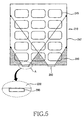
- FIG 4 is a top view briefly showing a part of a keypad assembly according to a second embodiment of the present invention
- FIG 5 is a top view showing a comparison illustration showing the advantages of the second embodiment of the present invention.
- the keypad assembly has a construction similar to that of the keypad assembly shown in FIG 2 , except that it has a diffusion member 330 on the lateral surface of the light guide panel 220'. Therefore, the same components are given the same reference numerals and repeated description thereof will be omitted to avoid redundancy.
- each light emitting device 290 has a predetermined emission angle, which creates shaded regions 310, where no light reaches, on both sides of each light emitting device 290.
- the film 247 has been removed from the magnified part B (enclosed by broken lines) in order to aid understanding of the present invention.
- the light guide panel 220' has a serrated diffusion member 330 positioned on the lateral surface thereof.
- the diffusion member 330 has a prism array structure and faces the light emitting devices 290.
- light incident on the diffusion member 330 from each light emitting device 290 is diffused by the diffusion member 330 and results in the same effect as that of a widening emission angle of the light emitting device 290.
- the shaded regions 320 on both sides of each light emitting device 290 are substantially reduced.
- the diffusion member 330 makes it possible to obtain more uniform luminance of the entire keypad 210' while minimizing the shaded regions 320, even when the light emitting devices 290 are positioned closer to the lateral surface of the light emitting panel 220'.
- the keypad and keypad assembly according to the present invention are advantageous in that the elastic light guide panel positioned between the key buttons and the protrusions makes it possible to illuminate the key buttons uniformly and brightly and reduce the number of light emitting devices, power consumption, and manufacture cost.
Abstract
Description
- The present invention relates to a keypad used in a portable terminal, and more particularly to a keypad and a keypad assembly having a light guide panel.
- A keypad used in a portable terminal typically includes an elastic pad plate, a plurality of key buttons formed on the upper surface of the elastic pad with characters printed on the upper surface thereof, respectively, and a plurality of protrusions (or actuators) formed on the lower surface of the elastic pad. This type of portable terminal normally has about 15-20 light emitting devices serving as a back light of the keypad. An example of illuminated keypad is disclosed in
US-A-5569367 . -
FIG 1 is a sectional view showing a keypad assembly according to the prior art. As shown, thekeypad assembly 100 includes akeypad 110, aswitch board 150, and a plurality of light emitting diodes(LEDs) 170. - The
keypad 110 includes anelastic pad 120 having the shape of a plate, a plurality ofkey buttons 140 formed on theupper surface 122 of theelastic pad 120 with characters, numbers, etc., printed on the upper surface thereof, respectively, and a plurality ofprotrusions 130 formed on thelower surface 124 of theelastic pad 120, which is opposite to theupper surface 122 of theelastic pad 120. Each of theprotrusions 130 is aligned with the center portion of thecorresponding key button 140. Theelastic pad 120 has a plurality ofgrooves 126 formed on thelower surface 124 thereof. Thegrooves 126 are positioned around therespective protrusions 130 to prevent theLEDs 170 from interfering with theprotrusions 130. - The
switch board 150 has a plate-shaped PCB(Printed Circuit Board) 155 and a plurality ofswitches 160 formed on the upper surface of the PCB 155 facing thekeypad 110. Eachswitch 160 is comprised of aconductive contact member 162 and aconductive dome 164 covering thecontact member 162 completely. - The plurality of
LEDs 170 are mounted on the upper surface of thePCB 155, and eachLED 170 is positioned to be covered by thecorresponding groove 126 of theelastic pad 120. - When the user presses one of the
key buttons 140, the portion of thekeypad 110 positioned beneath the pressedkey button 140 deforms towards theswitch board 150. As a result, one of theprotrusions 130 corresponding to the deformed portion presses thecorresponding dome 164, thus providing an electrical contact with thecorresponding contact member 162. - Due to the operation of the
switches 160 in the vicinity, theLEDs 170 must not be positioned beneath thecorresponding key buttons 140. Light outputted from therespective LEDs 170 passes through theelastic pad 120 and illuminates therespective key buttons 140 at an oblique angle. As a result, thekey buttons 140 are dimly illuminated in a non-uniformly fashion. In particular, the center of eachkey button 140 looks darker, and the periphery thereof looks brighter. If more LEDs are installed to enhance an uniform illumination of thekey buttons 140, power consumption and manufacturing cost increase. - Accordingly, the present invention has been made to solve the above-mentioned problems occurring in the prior art and provides additional advantages, by providing a keypad and a keypad assembly capable of realizing high and uniform brightness, while consuming less power and costing less.
- In one embodiment, there is provided a keypad including a light guide panel, the interior of which light propagates through; a film positioned on the upper surface of the light guide panel and having at least one key button positioned on the upper surface thereof; and at least one reflective pattern fixedly positioned with respect to the light guide panel to reflect a part of the light, which propagates through the interior of the light guide panel, towards the key button.
- In another embodiment, there is provided a keypad assembly including a keypad having a light guide panel, the interior of which light propagates through, and a film positioned on the upper surface of the light guide panel with at least one key button positioned on the upper surface of the film and a switch board having at least one switch formed on its upper surface, which faces the keypad, wherein as the key button is pressed, the portion of the keypad deformed towards the switch board presses the switch.
- In yet another embodiment, there is provided a portable terminal including a switch board having at least one switch positioned on the upper surface thereof; a keypad having a light guide panel with upper, lower, and lateral surfaces; and at least one light emitting device positioned adjacent to at least one of the lateral surfaces of the light guide panel, wherein the keypad includes a film positioned on the upper surface of the light guide panel and having at least one key button positioned on the upper surface thereof and at least one reflective pattern locally formed on the light guide panel to reflect a part of light, which propagates through the interior of the light guide panel, towards the key button.
- The above features, and advantages of the present invention will be more apparent from the following detailed description taken in conjunction with the accompanying drawings, in which:
-
FIG 1 is a sectional view showing a keypad assembly according to the prior art; -
FIG 2 is a sectional view showing a keypad assembly according to a first embodiment of the present invention; -
FIG 3 is a top view briefly showing a part of the keypad assembly shown inFIG 2 ; -
FIG 4 is a top view briefly showing a part of a keypad assembly according to a second embodiment of the present invention; and -
FIG 5 is a top view showing an example for comparison with the second embodiment of the present invention. - Hereinafter, embodiments of the present invention will be described with reference to the accompanying drawings. For the purposes of clarity and simplicity, a detailed description of known functions and configurations incorporated herein is omitted to avoid making the subject matter of the present invention unclear.
-
FIG 2 is a sectional view showing a keypad assembly according to a first embodiment of the present invention, andFIG. 3 is a top view briefly showing a part of the keypad assembly. - Referring to
FIG 2 , thekeypad assembly 200 includes akeypad 210, aswitch board 250 facing thekeypad 210, at least onelight emitting device 290, and asecond PCB 280. - The
keypad 210 includes alight guide panel 220, afilm 247, a plurality ofkey buttons 245, a plurality ofprotrusions 240, and a plurality of reflective patterns 230 (indicated by solid triangles). - The
light guide panel 220 guides light coupled to the interior thereof The coupled light propagates from a lateral surface of thelight guide panel 220 to the opposite lateral surface thereof. Thelight guide panel 220 may have any shape, such as a square. The light coupled to the interior of thelight guide panel 220 propagates into thelight guide panel 220 due to a total reflection at the interface between thelight guide panel 220 and the external air layer. Thelight guide panel 220 has elasticity so that thekey buttons 245, when pressed, can return to the original position. That is, thelight guide panel 220 has self-restoration properties so that it can restore the original shape after deformation and, after thekey buttons 245 are operated, returns them to the original position. - Conventional light guide panels are manufactured by injection-molding process using polycarbonate or acryl-based resin which has a high transmittance for visible rays. They have low elastic modulus, poor elastic restoration properties, and high hardness. This makes it difficult to obtain a good click feel when pressing key buttons. Also, when a key button is pressed, adjacent key buttons may be erroneously operated together (interference among key buttons). Further, permanent deformation may easily occur after repeated operation.
- Therefore, the
light guide panel 220 according to the present invention is made of a highly transparent elastomer material, preferably polyurethane or silicone, which has low hardness, high elastic modulus, excellent elastic restoration properties, and high optical transmittance, in order to provide a good click feel, suppress interference amongkey buttons 245, and avoid permanent deformation even after repeated operation. - The
film 247 is disposed on the upper surface of thelight guide panel 220, and it has a plurality ofkey buttons 245 positioned on the upper surface thereof. The periphery of thefilm 247 is attached to the periphery of thelight guide panel 220 using anadhesion member 249 to bond and maintain an upper air layer between thefilm 247 and thelight guide panel 220. Also, there is a lower air layer beneath thelight guide panel 220, and it prevents light, which is supposed to illuminate thekey buttons 245, from leaking via theadhesion member 249. Light propagates between the interfaces between thelight guide panel 220 and the upper and lower air layers due to total reflection. If the condition of total reflection is not maintained at the interface between thelight guide panel 220 and theadhesion member 249, unnecessary leakage of light may occur. Theadhesion member 249 is preferably positioned on the periphery of thelight guide panel 220 as the rest of light which is not used to illuminate thekey buttons 245 reaches the periphery of thelight guide panel 220. Thefilm 247 preferably has such surface properties that it is not attached to the upper surface of thelight guide panel 220, because, if the center of thefilm 247 having the key buttons positioned thereon is attached to the upper surface of thelight guide panel 220, no air layer can be maintained between thelight guide panel 220 and thefilm 247. To this end, the surface of thefilm 247 may be roughened or coated with a releasing agent in order to provide the surface with slipperiness. In addition, a portion of the upper surface of thefilm 247, which has nokey button 245 positioned thereon, may be subjected to printing to prevent light from emerging from portions other than thekey buttons 245. - The
film 247 may be made of a highly transparent elastomer material, preferably polyurethane or silicone, which has low hardness, high elastic modulus, excellent elastic restoration properties, and high optical transmittance. - When the
whole film 247 is attached to the upper surface of thelight guide panel 220, the refractive index of thefilm 247 is set to be lower than that of thelight guide panel 220 and the attachment surface (or lower surface) of the film is printed or coated with a layer, which is made of a material having high reflectance, to minimize unnecessary loss of light. - The plurality of
key buttons 245 is positioned on the upper surface of thefilm 247 and have characters, numeral, etc. printed on the upper surface thereof, respectively. Eachkey button 245 may be attached to the upper surface of thefilm 247 by a corresponding adhesion member or may be formed as an integrated one piece with thefilm 247. Eachkey button 245 may be made of the same material as thefilm 247 or made of polycarbonate or acryl-based resin. Eachkey button 245 may have any shape, such as a circular post or elliptical post. - The plurality of
protrusions 240 is positioned on thelower surface 224 of thelight guide panel 220, which is opposite to theupper surface 222 of thelight guide panel 220. Theprotrusions 240 may be formed in one piece with thelight panel 220 using a material identical to or different from that of thelight guide panel 220. Alternatively, theprotrusions 240 may be separately formed and attached to thelower surface 224 of thelight guide panel 220. Eachprotrusion 240 may have any shape, such as a truncated cone or trapezoidal hexahedron. Eachprotrusion 240 is aligned under the corresponding key button 245 (in a thickness direction of thekeypad assembly 200 or a perpendicular direction to the upper surface of the first PCB 260). - The
keypad 210 has a plurality ofreflective patterns 230 formed on the lower surface of thelight guide panel 220 to reflect a part of light, which propagates into thelight guide panel 220, towards the correspondingkey buttons 245, respectively. If necessary, eachreflective pattern 230 may be formed on the upper surface of thelight guide panel 220 or positioned between thelight guide panel 220 and thecorresponding protrusion 240. Eachreflective pattern 230 is formed at and around theprotrusion 240 positioned just under the correspondingkey button 245 to uniformly illuminate it. In theentire keypad 210, the density or size of reflective patterns positioned closer to thelight emitting device 290 is different from that of reflective patterns positioned farther away from thelight emitting device 290. This is done in order to uniformly adjust the overall distribution of light quantity emerging from the upper side of thelight guide panel 220 regardless of the distance from thelight emitting device 290. For example, when the amount of light emerging from positions closer to thelight emitting device 290 is larger, the density of reflective patterns closer to thelight emitting device 290 is set to be lower. When the amount of light emerging from positions farther away from thelight emitting device 290 is smaller, the density of reflective patterns farther away from the light emitting device is set to be higher. In this manner, the distribution of quantity of emergent light, particularly the overall illumination distribution of thekey buttons 245 can be uniform and bright. - The
central portion 232 of eachreflective pattern 230 is formed on the lower surface of thecorresponding protrusion 240, and theperipheral portion 234 thereof is formed around theprotrusion 240. As shown, light propagating into thelight guide panel 220 due to total reflection is incident on thereflective patterns 230. Most light diffuse reflected by thereflective patterns 230 towards akey button 245 cannot satisfy the condition of total reflection (when incident angle is smaller than critical angle) and passes through thefilm 247 and the correspondingkey button 245 to the exterior. In addition, light passing through thereflective patterns 230 without diffuse reflection and a part of the diffuse reflected light satisfying the condition of total reflection, continuously propagate inside thelight guide panel 220 while contributing to illuminate other key buttons. In this manner, eachreflective pattern 230 causes diffuse reflection and use only a part of incident light for illumination of the correspondingkey button 245, and the rest is used for illumination of other key buttons. Furthermore, thereflective patterns 230 provide uniform illumination of thekey button 245 by means of diffuse reflection in an arbitrary direction. Preferably, thereflective patterns 230 are formed by scratching or printing. - The
switch board 250 includes afirst PCB 260 and adome sheet 270. - The
first PCB 260 has a plurality ofconductive contact members 265 formed on the upper surface thereof, which constituteswitches corresponding domes 275. Theswitches protrusions 240. - The
dome sheet 270 is attached to the upper surface of thefirst PCB 260 and has a plurality of semi-sphericalconductive domes 275, which completely cover thecorresponding contact members 265. - When the user presses one of the
key buttons 245, the portion of thekeypad 210 positioned beneath the pressedkey button 245 deforms towards theswitch board 250. As a result, one of theprotrusions 240 corresponding to the deformed portion presses thecorresponding dome 275, which then makes electrical contact with thecorresponding contact member 265. When thelight guide panel 220 is made of an elastomer material, it has a sticky surface and thedomes 275 are likely to be attached to the lower surface of thelight guide panel 220. Therefore, the surface of eachdome 275 may be roughed or coated with a releasing agent in order to provide the surface with slipperiness. - The
second PCB 280 is attached to the periphery of thelower surface 224 of thelight guide panel 220. Thelight emitting device 290 is mounted on the upper surface of thesecond PCB 280 with its light emitting surface facing the lateral surface of thelight guide panel 220. Light emerging from thelight emitting device 290 is coupled to the interior of thelight guide panel 220 via the lateral surface thereof Thesecond PCB 280 may be made of a conventional flexible PCB (FPCB), and the light emitting device may be a conventional LED. - In the present embodiment, the
second PCB 280 may be removed and a peripheral portion of thelight guide panel 220 may extend with a slant to the upper surface of thefirst PCB 260 in the shape of a wedge. Thelight emitting device 290 is then mounted on the upper surface of thefirst PCB 260. - Alternatively, the
second PCB 280 may be removed and a peripheral portion of thelight guide panel 220 may be bent so that it extends to the upper surface of thefirst PCB 260. Thelight emitting device 290 is then mounted on the upper surface of thefirst PCB 260. -
FIG 4 is a top view briefly showing a part of a keypad assembly according to a second embodiment of the present invention, andFIG 5 is a top view showing a comparison illustration showing the advantages of the second embodiment of the present invention. The keypad assembly has a construction similar to that of the keypad assembly shown inFIG 2 , except that it has adiffusion member 330 on the lateral surface of the light guide panel 220'. Therefore, the same components are given the same reference numerals and repeated description thereof will be omitted to avoid redundancy. - In
FIG 5 , thefilm 247 has been removed from the magnified part A (enclosed by broken lines) to assist in better understanding of the present invention. As shown, light emerging from thelight emitting devices 290 is coupled to the interior of thelight guide panel 220 via the lateral surface thereof. Eachlight emitting device 290 has a predetermined emission angle, which creates shadedregions 310, where no light reaches, on both sides of each light emittingdevice 290. - Referring back to
FIG 4 , thefilm 247 has been removed from the magnified part B (enclosed by broken lines) in order to aid understanding of the present invention. As shown, the light guide panel 220' has aserrated diffusion member 330 positioned on the lateral surface thereof. Thediffusion member 330 has a prism array structure and faces thelight emitting devices 290. Hence, light incident on thediffusion member 330 from each light emittingdevice 290 is diffused by thediffusion member 330 and results in the same effect as that of a widening emission angle of thelight emitting device 290. As a result, theshaded regions 320 on both sides of each light emittingdevice 290 are substantially reduced. Thediffusion member 330 makes it possible to obtain more uniform luminance of the entire keypad 210' while minimizing the shadedregions 320, even when thelight emitting devices 290 are positioned closer to the lateral surface of the light emitting panel 220'. - As mentioned above, the keypad and keypad assembly according to the present invention are advantageous in that the elastic light guide panel positioned between the key buttons and the protrusions makes it possible to illuminate the key buttons uniformly and brightly and reduce the number of light emitting devices, power consumption, and manufacture cost.
- While the invention has been shown and described with reference to certain preferred embodiments thereof, it will be understood by those skilled in the art that various changes in form and details may be made therein without departing from the appended claims.
Claims (15)
- A keypad (210) comprising:a light guide panel (220) for propagating light therethrough due to a total reflection;a film (247) disposed above the light guide panel (220);a plurality of key buttons (245) disposed on an upper surface of the film (247) characterisedin that a plurality of reflective patterns (230) are formed on the light guide panel (220) and spaced from each other to output a part of the light propagating through the interior of the light guide panel (220) towards the key button.
- The keypad as claimed in claim 1, wherein the periphery of the film (247) is attached to the periphery of the light guide panel (220) by an adhesion member (249);
wherein an upper air layer is provided between the central portion of the film (247) and the light guide panel (220);
wherein a lower air layer is provided beneath the light guide panel (220), such that light propagates between the light guide panel (220) and the upper and lower air layers due to total reflection. - The keypad as claimed in claim 2, wherein the upper air layer is disposed between a portion of the film (247) on which the key button (245) is disposed and a portion of light guide panel (220) facing the portion of the film (247).
- The keypad as claimed in any of claims 1 to 3, wherein a space between the film (247) and the light guide panel (220) is uniform.
- The keypad as claimed in any of claims 1 to 4, wherein a lower surface of the portion of the film (247) on which the key button (245) is disposed and an upper surface of the light guide panel (220) are flat.
- The keypad as claimed in any of claims 1 to 5, wherein the reflective pattern (230) is formed to correspond to the key button (245).
- The keypad as claimed in any of claims 1 to 6, further comprising a plurality of protrusions (240) provided on a lower portion of or beneath the light guide panel (220).
- The keypad as claimed in any of claims 1 to 7, wherein the reflective pattern (230) causes a diffuse reflection of the light guided through the interior of the light guide panel (220) due to the total reflection.
- The keypad as claimed in claim 7 or 8, wherein the light guide panel (220) is made of a material different from that of the protrusion (240).
- The keypad as claimed in any of claims 1 to 9, wherein the light guide panel (220) has elasticity so that the plurality of key buttons (245) can be operated individually without interference among the plurality of key buttons (245), has self-restoration properties, propagates the light therethrough from one lateral surface of the light guide panel (220) to another lateral surface of the light guide panel (220) opposite to the one lateral surface, and maintains the plurality of key buttons (245).
- A keypad assembly comprising: a keypad as claimed in any of claims 1 to 10, and a switch board (260) having at least one switch (265, 275) on its upper surface, which faces the light guide panel (220), wherein the switch (265, 275) is activated by pressing the key button (245).
- The keypad assembly as claimed in claim 11, further comprising at least one light emitting device (290) which is disposed to face the one lateral surface of the light guide panel (220) and couples light to the interior of the light guide panel (220).
- The keypad assembly as claimed in claim 12, further comprising a printed circuit board, wherein the light emitting device is mounted on the printed circuit board.
- The keypad assembly as claimed in any of claims 11 to 13, wherein the switch (265, 275) comprises a conductive contact member (265) formed to correspond the key button (245) and a conductive dome (275) covering the contact member (265), and
wherein as the protrusion (240) is moved by pressing the key button (245), the protrusion (240) presses the conductive dome (275), thus providing an electrical contact between the conductive dome (275) and the conductive contact member (265). - A portable terminal comprising: the keypad assembly (200) according to any of claims 11 to 14.
Priority Applications (1)
| Application Number | Priority Date | Filing Date | Title |
|---|---|---|---|
| PL10184445T PL2270825T3 (en) | 2005-05-19 | 2005-10-04 | Keypad and keypad assembly |
Applications Claiming Priority (4)
| Application Number | Priority Date | Filing Date | Title |
|---|---|---|---|
| KR1020050042035A KR100606081B1 (en) | 2005-05-19 | 2005-05-19 | Light guide panel, keypad and keypad assembly |
| KR1020050064351A KR100606082B1 (en) | 2005-07-15 | 2005-07-15 | Keypad and keypad assembly |
| EP08006381A EP1944782B1 (en) | 2005-05-19 | 2005-10-04 | Keypad and keypad assembly |
| EP05021645A EP1732094B1 (en) | 2005-05-19 | 2005-10-04 | Keypad and keypad assembly |
Related Parent Applications (2)
| Application Number | Title | Priority Date | Filing Date |
|---|---|---|---|
| EP05021645.6 Division | 2005-10-04 | ||
| EP08006381.1 Division | 2008-03-31 |
Publications (2)
| Publication Number | Publication Date |
|---|---|
| EP2270825A1 EP2270825A1 (en) | 2011-01-05 |
| EP2270825B1 true EP2270825B1 (en) | 2012-07-04 |
Family
ID=35708986
Family Applications (4)
| Application Number | Title | Priority Date | Filing Date |
|---|---|---|---|
| EP10184445A Active EP2270825B1 (en) | 2005-05-19 | 2005-10-04 | Keypad and keypad assembly |
| EP08006381A Active EP1944782B1 (en) | 2005-05-19 | 2005-10-04 | Keypad and keypad assembly |
| EP05021645A Active EP1732094B1 (en) | 2005-05-19 | 2005-10-04 | Keypad and keypad assembly |
| EP05021650A Not-in-force EP1724800B1 (en) | 2005-05-19 | 2005-10-04 | Key pad and keypad assembly |
Family Applications After (3)
| Application Number | Title | Priority Date | Filing Date |
|---|---|---|---|
| EP08006381A Active EP1944782B1 (en) | 2005-05-19 | 2005-10-04 | Keypad and keypad assembly |
| EP05021645A Active EP1732094B1 (en) | 2005-05-19 | 2005-10-04 | Keypad and keypad assembly |
| EP05021650A Not-in-force EP1724800B1 (en) | 2005-05-19 | 2005-10-04 | Key pad and keypad assembly |
Country Status (12)
| Country | Link |
|---|---|
| US (5) | US7294803B2 (en) |
| EP (4) | EP2270825B1 (en) |
| JP (4) | JP4732230B2 (en) |
| CN (2) | CN101145458B (en) |
| AT (3) | ATE418149T1 (en) |
| BR (2) | BRPI0601292B1 (en) |
| DE (2) | DE602005011768D1 (en) |
| ES (3) | ES2390653T3 (en) |
| PL (1) | PL2270825T3 (en) |
| RU (3) | RU2332743C2 (en) |
| TW (2) | TWI313018B (en) |
| WO (2) | WO2006123882A1 (en) |
Families Citing this family (116)
| Publication number | Priority date | Publication date | Assignee | Title |
|---|---|---|---|---|
| JP4305212B2 (en) * | 2004-02-18 | 2009-07-29 | 日本電気株式会社 | Mobile phone and manufacturing method thereof |
| KR100651417B1 (en) * | 2005-07-15 | 2006-11-29 | 삼성전자주식회사 | Lighting apparatus for key pad of portable terminal |
| KR100770827B1 (en) * | 2005-07-15 | 2007-10-26 | 삼성전자주식회사 | Keypad and keypad assembly |
| KR100787581B1 (en) * | 2005-09-27 | 2007-12-21 | 삼성전자주식회사 | Keypad having phosphor, keypad assembly and portable terminal |
| JP2007150846A (en) | 2005-11-29 | 2007-06-14 | Toshiba Corp | Contents reproducing system |
| KR100744283B1 (en) * | 2005-12-05 | 2007-07-30 | 삼성전자주식회사 | Key-pad and fabricating method using the same |
| US7683279B2 (en) * | 2006-02-28 | 2010-03-23 | Hyun Soo Kim | Light emitting keypad comprising light guide film and light guide |
| DE202006004575U1 (en) * | 2006-03-22 | 2006-05-18 | Trw Automotive Electronics & Components Gmbh & Co. Kg | switch module |
| KR100754686B1 (en) * | 2006-03-28 | 2007-09-03 | 삼성전자주식회사 | Keypad assembly |
| KR100676480B1 (en) * | 2006-04-25 | 2007-02-02 | 주식회사 케이비에프 | Pcb with light guide plate for handheld device |
| JP4926762B2 (en) * | 2006-08-03 | 2012-05-09 | シチズン電子株式会社 | Luminescent sheet module |
| TWM306669U (en) * | 2006-08-04 | 2007-02-21 | Wintek Corp | Backlight module, backlight module housing and liquid crystal display having the same |
| US7498534B2 (en) * | 2006-08-30 | 2009-03-03 | 3M Innovative Properties Company | Keypad light guide |
| KR101228452B1 (en) * | 2006-09-12 | 2013-01-31 | 엘지전자 주식회사 | Keypad assembly and mobile terminal having it |
| KR100773558B1 (en) * | 2006-10-11 | 2007-11-07 | 삼성전자주식회사 | Keypad assembly for electronic equipment |
| KR101243669B1 (en) * | 2006-10-18 | 2013-03-25 | 엘지전자 주식회사 | Mobile terminal |
| CN101192478B (en) * | 2006-12-01 | 2010-08-11 | 深圳富泰宏精密工业有限公司 | Backlight keyboard |
| JP4845701B2 (en) * | 2006-12-14 | 2011-12-28 | シチズン電子株式会社 | Seat switch module |
| JP5060921B2 (en) * | 2006-12-26 | 2012-10-31 | アルプス電気株式会社 | Movable contact unit for switch and switch device using the same |
| KR100856206B1 (en) * | 2007-01-31 | 2008-09-03 | 삼성전자주식회사 | Keypad and keypad assembly |
| US20080191904A1 (en) * | 2007-02-12 | 2008-08-14 | Kai-Jie Tsao | Method For Manufacturing Thin Keypad Assembly And Such Assembly |
| WO2008102196A1 (en) * | 2007-02-23 | 2008-08-28 | Nokia Corporation | Optical actuators in keypads |
| US8471832B2 (en) * | 2007-03-02 | 2013-06-25 | Samsung Electronics Co., Ltd. | Keypad assembly having light leakage prevention structure |
| JP2008226576A (en) * | 2007-03-12 | 2008-09-25 | Sunarrow Ltd | Key sheet, key unit equipped with it, and manufacturing method of light guide plate of key sheet |
| EP1970735A1 (en) * | 2007-03-12 | 2008-09-17 | Silitech Technology Corp. | Super-thin light-guiding module with a side light-projecting type function |
| TWI315537B (en) * | 2007-03-14 | 2009-10-01 | Ichia Tech Inc | Method for manufacturing compact keypad |
| JP4908280B2 (en) * | 2007-03-20 | 2012-04-04 | 住友電工プリントサーキット株式会社 | Method for manufacturing light guide plate |
| JP2008235021A (en) * | 2007-03-20 | 2008-10-02 | Sumitomo Electric Printed Circuit Inc | Input module and portable equipment |
| JP2008235025A (en) * | 2007-03-20 | 2008-10-02 | Sumitomo Electric Printed Circuit Inc | Light guide plate, input module and portable apparatus |
| KR20080088324A (en) * | 2007-03-29 | 2008-10-02 | 삼성전자주식회사 | Keypad assembly |
| JP2008269864A (en) * | 2007-04-18 | 2008-11-06 | Sunarrow Ltd | Metal dome sheet equipped with pressing protrusion, and push-button switch |
| JP2008282598A (en) * | 2007-05-09 | 2008-11-20 | Sunarrow Ltd | Key sheet and key unit equipped with it |
| US7718910B2 (en) * | 2007-06-20 | 2010-05-18 | Panasonic Corporation | Movable contact assembly and switch using the same |
| CN101364487A (en) * | 2007-08-09 | 2009-02-11 | 鸿富锦精密工业(深圳)有限公司 | Illuminant keyboard |
| TR200705956A2 (en) * | 2007-08-28 | 2009-03-23 | Vestel Elektroni̇k Sanayi̇ Ve Ti̇caret Anoni̇m Şi̇rketi̇@ | Keypad with light reflecting keys for homogeneous visibility |
| JP2009070717A (en) * | 2007-09-14 | 2009-04-02 | Citizen Electronics Co Ltd | Sheet switch |
| JP2009087818A (en) * | 2007-10-01 | 2009-04-23 | Shin Etsu Polymer Co Ltd | Illumination sheet member and cover member for control switch |
| EP2056317B1 (en) * | 2007-10-29 | 2011-04-27 | Research In Motion Limited | Illuminated key-pad assembly |
| US7671290B2 (en) | 2007-10-29 | 2010-03-02 | Research In Motion Limited | Illuminated key-pad assembly |
| CN101430975A (en) * | 2007-11-08 | 2009-05-13 | 鸿富锦精密工业(深圳)有限公司 | Illuminant keyboard |
| TWI345719B (en) * | 2007-11-15 | 2011-07-21 | Lite On Technology Corp | Light emitting keyboard |
| KR101345384B1 (en) * | 2007-11-16 | 2013-12-24 | 삼성전자주식회사 | light guide plate, lighting apparatus using the plate and fabrication method of the plate |
| TWI394110B (en) * | 2007-12-14 | 2013-04-21 | Chi Mei Comm Systems Inc | Icon dispaly |
| JP2009152099A (en) * | 2007-12-21 | 2009-07-09 | Shin Etsu Polymer Co Ltd | Illuminating structure for mobile phone |
| CN101471192B (en) * | 2007-12-27 | 2011-04-06 | 比亚迪股份有限公司 | Press key structure and method for producing the same |
| TWM334393U (en) * | 2008-01-04 | 2008-06-11 | Silitech Technology Corp | Thin keystroke module having reflection structure |
| JP5293068B2 (en) * | 2008-01-07 | 2013-09-18 | パナソニック株式会社 | Movable contact body |
| US7498533B1 (en) * | 2008-02-27 | 2009-03-03 | Silitek Electronic(Guangzhou)Co.,Ltd. | Keypad device |
| TWM341265U (en) * | 2008-03-05 | 2008-09-21 | Global Lighting Technologies Taiwan Inc | Light emitting key structure |
| JP5145595B2 (en) * | 2008-04-04 | 2013-02-20 | 住友電工プリントサーキット株式会社 | Light guide plate and wiring module |
| JP2009289743A (en) * | 2008-04-28 | 2009-12-10 | Citizen Electronics Co Ltd | Sheet switch module |
| TWI402717B (en) * | 2008-05-13 | 2013-07-21 | Chicony Electronic Co Ltd | Glowing keyboard |
| WO2009157218A1 (en) * | 2008-06-26 | 2009-12-30 | 日本メクトロン株式会社 | Key module of portable apparatus |
| KR101479339B1 (en) * | 2008-07-09 | 2015-01-05 | 삼성전자주식회사 | Illumination apparatus using light guide and portable terminal having the same |
| JP4722975B2 (en) * | 2008-08-25 | 2011-07-13 | 三井物産プラスチックトレード株式会社 | Small portable electronic devices |
| JP2010062086A (en) | 2008-09-05 | 2010-03-18 | Sunarrow Ltd | Light guide sheet, and key sheet using the same |
| US8128297B2 (en) * | 2008-09-11 | 2012-03-06 | Zippy Technology Corp. | Self-luminous keyboard with brightness-enhanced keycaps |
| ATE510234T1 (en) * | 2008-10-08 | 2011-06-15 | Research In Motion Ltd | KEYBOARD ASSEMBLY TO MINIMIZE EMISSION OF LIGHT FROM UNINTENDED PATHS |
| JP5543094B2 (en) * | 2008-10-10 | 2014-07-09 | ピーエスフォー ルクスコ エスエイアールエル | Low noise semiconductor package |
| JP2010097801A (en) * | 2008-10-16 | 2010-04-30 | Alps Electric Co Ltd | Input device having illumination function |
| JP5204017B2 (en) * | 2009-03-19 | 2013-06-05 | アルプス電気株式会社 | Keyboard device having illumination function |
| US7608792B1 (en) * | 2008-11-17 | 2009-10-27 | Sunrex Technology Corp. | Membrane keyboard/keypad with arrangement for uniformly lighting keys from background |
| US8500348B2 (en) * | 2008-11-24 | 2013-08-06 | Logitech Europe S.A. | Keyboard with ultra-durable keys |
| SG172218A1 (en) * | 2008-12-17 | 2011-07-28 | Sinco Technologies Pte Ltd | Light diffuser actuator film (ldaf) keypad module |
| JP5171656B2 (en) * | 2009-01-09 | 2013-03-27 | シャープ株式会社 | Light guide sheet, key input device, and portable terminal |
| US20100200381A1 (en) * | 2009-02-10 | 2010-08-12 | Shih-Yuan Kuo | Key module |
| US8142036B2 (en) * | 2009-03-12 | 2012-03-27 | Avago Technologies Ecbu Ip (Singapore) Pte. Ltd. | Keypad device with light source and reflector |
| US8317384B2 (en) * | 2009-04-10 | 2012-11-27 | Intellectual Discovery Co., Ltd. | Light guide film with cut lines, and optical keypad using such film |
| TWI401717B (en) * | 2009-12-28 | 2013-07-11 | Darfon Electronics Corp | Masking, backlight module, and lighting keyboard |
| US8432678B2 (en) * | 2010-01-06 | 2013-04-30 | Apple Inc. | Component assembly |
| US8172413B2 (en) * | 2010-02-24 | 2012-05-08 | Avago Technologies Ecbu Ip (Singapore) Pte. Ltd. | Keypad assembly |
| KR20110131437A (en) * | 2010-05-31 | 2011-12-07 | 엘지전자 주식회사 | Mobile terminal |
| TW201227012A (en) * | 2010-12-21 | 2012-07-01 | Ichia Tech Inc | Light guide structure, keypad structure including the same, and method of fabricating the same |
| KR101901610B1 (en) * | 2011-11-03 | 2018-09-28 | 엘지전자 주식회사 | Portable terminal |
| US9087659B2 (en) * | 2011-11-29 | 2015-07-21 | Razer (Asia-Pacific) Pte. Ltd. | Optically transmissive key switch mechanism for display-capable keyboards, keypads, or other user input devices |
| US9070520B2 (en) * | 2012-04-19 | 2015-06-30 | Giga-Byte Technology Co., Ltd. | Illumination module and illuminated keyboard having the same |
| JP2012199254A (en) * | 2012-07-23 | 2012-10-18 | Sumitomo Electric Printed Circuit Inc | Wiring board module and electronic apparatus |
| CN103578831B (en) * | 2012-08-09 | 2016-07-06 | 光宝电子(广州)有限公司 | Pressure type backlight button structure |
| US9502193B2 (en) | 2012-10-30 | 2016-11-22 | Apple Inc. | Low-travel key mechanisms using butterfly hinges |
| US9710069B2 (en) | 2012-10-30 | 2017-07-18 | Apple Inc. | Flexible printed circuit having flex tails upon which keyboard keycaps are coupled |
| US9449772B2 (en) | 2012-10-30 | 2016-09-20 | Apple Inc. | Low-travel key mechanisms using butterfly hinges |
| TWM448778U (en) * | 2012-11-02 | 2013-03-11 | Darfon Electronics Corp | Protective cover and keyboard |
| CN105144017B (en) | 2013-02-06 | 2018-11-23 | 苹果公司 | Input-output apparatus with the appearance and function that are dynamically adapted |
| US9412533B2 (en) | 2013-05-27 | 2016-08-09 | Apple Inc. | Low travel switch assembly |
| US9908310B2 (en) | 2013-07-10 | 2018-03-06 | Apple Inc. | Electronic device with a reduced friction surface |
| CN103515135A (en) * | 2013-09-23 | 2014-01-15 | 苏州达方电子有限公司 | Thin keyboard |
| KR102108067B1 (en) * | 2013-09-24 | 2020-05-08 | 엘지전자 주식회사 | Mobile terminal and method light giud unit |
| WO2015047606A1 (en) | 2013-09-30 | 2015-04-02 | Apple Inc. | Keycaps having reduced thickness |
| EP3014396A1 (en) | 2013-09-30 | 2016-05-04 | Apple Inc. | Keycaps with reduced thickness |
| US9793066B1 (en) | 2014-01-31 | 2017-10-17 | Apple Inc. | Keyboard hinge mechanism |
| US9779889B2 (en) | 2014-03-24 | 2017-10-03 | Apple Inc. | Scissor mechanism features for a keyboard |
| US9704665B2 (en) | 2014-05-19 | 2017-07-11 | Apple Inc. | Backlit keyboard including reflective component |
| US9715978B2 (en) | 2014-05-27 | 2017-07-25 | Apple Inc. | Low travel switch assembly |
| US10796863B2 (en) | 2014-08-15 | 2020-10-06 | Apple Inc. | Fabric keyboard |
| US10082880B1 (en) | 2014-08-28 | 2018-09-25 | Apple Inc. | System level features of a keyboard |
| WO2016053911A2 (en) | 2014-09-30 | 2016-04-07 | Apple Inc. | Venting system and shield for keyboard assembly |
| CN104766739B (en) * | 2015-03-16 | 2017-11-17 | 上海与德科技有限公司 | Formal dress side key component |
| CN206134573U (en) | 2015-05-13 | 2017-04-26 | 苹果公司 | Key, be used for key of keyboard and be used for electron device's input structure |
| EP3295467A1 (en) | 2015-05-13 | 2018-03-21 | Apple Inc. | Keyboard for electronic device |
| CN207367843U (en) | 2015-05-13 | 2018-05-15 | 苹果公司 | Keyboard components |
| CN205595253U (en) | 2015-05-13 | 2016-09-21 | 苹果公司 | Electron device , Hinge structure and key mechanism |
| US9934915B2 (en) | 2015-06-10 | 2018-04-03 | Apple Inc. | Reduced layer keyboard stack-up |
| US9971084B2 (en) | 2015-09-28 | 2018-05-15 | Apple Inc. | Illumination structure for uniform illumination of keys |
| CN106877855A (en) * | 2015-12-14 | 2017-06-20 | 致伸科技股份有限公司 | Optical switch keyboard |
| JP6586527B2 (en) * | 2015-12-31 | 2019-10-02 | シェンジェン ロイオル テクノロジーズ カンパニー リミテッドShenzhen Royole Technologies Co., Ltd. | Terminal and electronic device |
| JP6633987B2 (en) * | 2016-07-22 | 2020-01-22 | 日立グローバルライフソリューションズ株式会社 | refrigerator |
| JP2018013305A (en) * | 2016-07-22 | 2018-01-25 | 日立アプライアンス株式会社 | refrigerator |
| US10353485B1 (en) | 2016-07-27 | 2019-07-16 | Apple Inc. | Multifunction input device with an embedded capacitive sensing layer |
| US10115544B2 (en) | 2016-08-08 | 2018-10-30 | Apple Inc. | Singulated keyboard assemblies and methods for assembling a keyboard |
| US10755877B1 (en) | 2016-08-29 | 2020-08-25 | Apple Inc. | Keyboard for an electronic device |
| US11500538B2 (en) | 2016-09-13 | 2022-11-15 | Apple Inc. | Keyless keyboard with force sensing and haptic feedback |
| CN106571257B (en) * | 2016-09-30 | 2019-01-22 | 东莞市名键电子科技有限公司 | Photo-electric mechanical switch and keyboard composition |
| CN117270637A (en) | 2017-07-26 | 2023-12-22 | 苹果公司 | Computer with keyboard |
| CN107421681B (en) * | 2017-07-31 | 2019-10-01 | 京东方科技集团股份有限公司 | A kind of pressure sensor and preparation method thereof |
| DE102018205831B3 (en) | 2018-04-17 | 2019-09-12 | Audi Ag | Operating element with movable probe element and motor vehicle with such a control element |
| CN110208899B (en) * | 2018-08-01 | 2021-02-26 | 光宝电子(广州)有限公司 | Backlight module and input device |
Family Cites Families (48)
| Publication number | Priority date | Publication date | Assignee | Title |
|---|---|---|---|---|
| US2886911A (en) * | 1953-07-23 | 1959-05-19 | George K C Hardesty | Duo-panel edge illumination system |
| JPS5686723U (en) * | 1979-12-07 | 1981-07-11 | ||
| JPS61202549A (en) | 1985-03-05 | 1986-09-08 | Matsushita Electric Ind Co Ltd | Key switching device with illumination |
| JPH03257728A (en) | 1990-03-07 | 1991-11-18 | Iri Design:Kk | Luminescence configuration for push type panel switch |
| JPH0422023A (en) | 1990-05-16 | 1992-01-27 | Matsushita Electric Ind Co Ltd | Keyboard |
| US5128842A (en) * | 1991-06-03 | 1992-07-07 | Sunarrow Co., Inc. | Uniform illumination plate |
| JPH05290669A (en) * | 1992-01-22 | 1993-11-05 | Fujikura Ltd | Lighting switch |
| US5397867A (en) * | 1992-09-04 | 1995-03-14 | Lucas Industries, Inc. | Light distribution for illuminated keyboard switches and displays |
| US5280145A (en) * | 1992-12-30 | 1994-01-18 | Jay-El Products, Inc. | Switch actuating mechanism |
| JP3318427B2 (en) * | 1994-01-21 | 2002-08-26 | ファナック株式会社 | Zero point correction method of pressure detection device in injection molding machine |
| KR960003475U (en) * | 1994-06-08 | 1996-01-22 | Lighting Remote Control | |
| US5491313A (en) | 1994-07-22 | 1996-02-13 | General Motors Corporation | Halo lighting for keypad switch assemblies |
| RU2088964C1 (en) * | 1994-07-22 | 1997-08-27 | Московский научно-исследовательский институт приборной автоматики | Keyboard for personal and miscellaneous electronic computers and hardware |
| JP3103833B2 (en) * | 1994-08-10 | 2000-10-30 | 信越ポリマー株式会社 | Illuminated pushbutton switch device |
| US5766981A (en) | 1995-01-04 | 1998-06-16 | Xerox Corporation | Thermally processed, phosphorus- or arsenic-containing semiconductor laser with selective IILD |
| JPH0982167A (en) * | 1995-09-08 | 1997-03-28 | Seikosha Co Ltd | Internally-illuminated pushbutton switch device |
| JP3100323B2 (en) * | 1995-10-06 | 2000-10-16 | 信越ポリマー株式会社 | Cover member for push button switch |
| US5661279A (en) * | 1995-10-26 | 1997-08-26 | Sunarrow Co., Ltd. | Pushbutton switch |
| US5895115A (en) * | 1996-01-16 | 1999-04-20 | Lumitex, Inc. | Light emitting panel assemblies for use in automotive applications and the like |
| JPH09259697A (en) * | 1996-01-16 | 1997-10-03 | Taisei Plus Kk | Switching seat structure for electronic equipment |
| DE29622180U1 (en) | 1996-12-20 | 1998-04-23 | Hansen & Reinders Gmbh | Switching devices such as contactors |
| JPH10199317A (en) * | 1997-01-17 | 1998-07-31 | Omron Corp | Surface light source device |
| US5847336A (en) * | 1997-05-02 | 1998-12-08 | Telefonaktiebolaget L M Ericsson (Publ) | Direct keypad backlighting |
| US5849336A (en) * | 1997-07-02 | 1998-12-15 | Abbott Laboratories | Method using sturgeon notochord for alleviating the symptoms of arthritis |
| JPH1173837A (en) * | 1997-08-28 | 1999-03-16 | Taisei Plas Co Ltd | Light irradiating type push button switch |
| US6633722B1 (en) | 1998-04-30 | 2003-10-14 | Nippon Zeon Co., Ltd. | Light guide plate with alicyclic resin |
| GB2345193B (en) * | 1998-12-22 | 2002-07-24 | Nokia Mobile Phones Ltd | Metallic keys |
| US6217183B1 (en) * | 1999-09-15 | 2001-04-17 | Michael Shipman | Keyboard having illuminated keys |
| JP2001167655A (en) | 1999-12-09 | 2001-06-22 | Citizen Electronics Co Ltd | Push button switch illumination apparatus |
| JP2001209328A (en) * | 2000-01-27 | 2001-08-03 | Tsuchiya Kogyo Kk | Electroluminescence display device of electronic apparatus |
| JP4407856B2 (en) | 2000-06-14 | 2010-02-03 | シチズン電子株式会社 | Electronics |
| JP4387049B2 (en) * | 2000-08-16 | 2009-12-16 | 株式会社エンプラス | Surface light source device and liquid crystal display |
| JP2002093270A (en) * | 2000-09-19 | 2002-03-29 | Nec Corp | Structure of illuminating part |
| JP2002300258A (en) | 2001-04-03 | 2002-10-11 | Nec Corp | Operation key lighting structure of portable terminal device |
| JP2003157738A (en) * | 2001-11-22 | 2003-05-30 | Stanley Electric Co Ltd | Key illumination device |
| TW509955B (en) * | 2001-11-30 | 2002-11-11 | Darfon Electronics Corp | Light emitting keyboard |
| JP2003178639A (en) | 2001-12-12 | 2003-06-27 | Sunarrow Ltd | Key unit with hard base |
| JP2003308752A (en) | 2002-04-17 | 2003-10-31 | Nec Access Technica Ltd | Lighting structure for operation part of portable terminal and portable terminal |
| US6926418B2 (en) | 2002-04-24 | 2005-08-09 | Nokia Corporation | Integrated light-guide and dome-sheet for keyboard illumination |
| JP2004061751A (en) | 2002-07-26 | 2004-02-26 | Semiconductor Energy Lab Co Ltd | Manufacturing method of display device |
| JP4119707B2 (en) * | 2002-08-02 | 2008-07-16 | ポリマテック株式会社 | Keypad, injection mold for resin key top, and method for manufacturing resin key top |
| JP4216577B2 (en) * | 2002-12-20 | 2009-01-28 | シチズン電子株式会社 | Light guide plate |
| JP2004227855A (en) * | 2003-01-21 | 2004-08-12 | Alps Electric Co Ltd | Illumination mechanism of rotating operation type electrical component |
| RU32636U1 (en) * | 2003-04-24 | 2003-09-20 | Открытое акционерное общество "Кировский завод "Маяк" | Control panel keyboard |
| AU2003274188A1 (en) * | 2003-10-23 | 2005-05-11 | Nokia Corporation | Keyboard with key supporting structure for portable electronics devices |
| KR100523081B1 (en) | 2003-12-11 | 2005-10-24 | 제일모직주식회사 | Light guide for back light unit |
| TWI231693B (en) * | 2004-01-12 | 2005-04-21 | Asustek Comp Inc | Translucent key structure and its manufacturing method |
| EP1571682A1 (en) * | 2004-03-02 | 2005-09-07 | Nec Corporation | Transmissive key sheet, input keys using transmissive key sheet and electronic equipment with input keys |
-
2005
- 2005-10-04 EP EP10184445A patent/EP2270825B1/en active Active
- 2005-10-04 AT AT05021650T patent/ATE418149T1/en not_active IP Right Cessation
- 2005-10-04 AT AT05021645T patent/ATE401659T1/en not_active IP Right Cessation
- 2005-10-04 DE DE602005011768T patent/DE602005011768D1/en active Active
- 2005-10-04 EP EP08006381A patent/EP1944782B1/en active Active
- 2005-10-04 ES ES10184445T patent/ES2390653T3/en active Active
- 2005-10-04 DE DE602005008209T patent/DE602005008209D1/en active Active
- 2005-10-04 AT AT08006381T patent/ATE548745T1/en active
- 2005-10-04 EP EP05021645A patent/EP1732094B1/en active Active
- 2005-10-04 ES ES05021650T patent/ES2318398T3/en active Active
- 2005-10-04 EP EP05021650A patent/EP1724800B1/en not_active Not-in-force
- 2005-10-04 PL PL10184445T patent/PL2270825T3/en unknown
- 2005-10-04 ES ES05021645T patent/ES2308358T3/en active Active
- 2005-12-15 US US11/300,942 patent/US7294803B2/en active Active
- 2005-12-27 CN CN2007101816924A patent/CN101145458B/en not_active Expired - Fee Related
- 2005-12-27 CN CN2007101817077A patent/CN101150019B/en active Active
-
2006
- 2006-01-06 US US11/327,029 patent/US7378606B2/en active Active
- 2006-03-31 TW TW095111421A patent/TWI313018B/en not_active IP Right Cessation
- 2006-03-31 TW TW095111435A patent/TWI314748B/en not_active IP Right Cessation
- 2006-04-19 BR BRPI0601292-2A patent/BRPI0601292B1/en not_active IP Right Cessation
- 2006-04-19 BR BRPI0601294-9A patent/BRPI0601294B1/en not_active IP Right Cessation
- 2006-04-20 RU RU2006113453/09A patent/RU2332743C2/en active
- 2006-05-10 JP JP2006131040A patent/JP4732230B2/en not_active Expired - Fee Related
- 2006-05-10 JP JP2006130983A patent/JP2006323843A/en active Pending
- 2006-05-16 WO PCT/KR2006/001823 patent/WO2006123882A1/en active Application Filing
- 2006-05-17 WO PCT/KR2006/001842 patent/WO2006123895A1/en active Application Filing
-
2007
- 2007-03-30 US US11/731,881 patent/US20070175744A1/en not_active Abandoned
- 2007-05-11 RU RU2007117683/09A patent/RU2007117683A/en not_active Application Discontinuation
- 2007-06-18 US US11/820,459 patent/US7462794B2/en active Active
- 2007-06-18 US US11/820,231 patent/US7446275B2/en active Active
-
2008
- 2008-03-18 RU RU2008110466/08A patent/RU2458382C2/en not_active IP Right Cessation
-
2009
- 2009-05-19 JP JP2009121009A patent/JP5008038B2/en not_active Expired - Fee Related
- 2009-11-20 JP JP2009264895A patent/JP2010044794A/en active Pending
Also Published As
Similar Documents
| Publication | Publication Date | Title |
|---|---|---|
| EP2270825B1 (en) | Keypad and keypad assembly | |
| KR100692742B1 (en) | Keypad having light guide layer and keypad assembly | |
| KR100606081B1 (en) | Light guide panel, keypad and keypad assembly | |
| KR100770827B1 (en) | Keypad and keypad assembly | |
| JP2006324253A (en) | Keypad device and mobile terminal | |
| KR100606082B1 (en) | Keypad and keypad assembly | |
| KR20060120512A (en) | Keypad and keypad assembly | |
| KR100744324B1 (en) | Keypad and keypad assembly | |
| KR20070009495A (en) | Keypad and keypad assembly | |
| KR20060119291A (en) | Keypad assembly | |
| KR100724897B1 (en) | Keypad assembly | |
| KR101023272B1 (en) | Keypad and keypad assembly | |
| KR20070036115A (en) | Keypad and keypad assembly |
Legal Events
| Date | Code | Title | Description |
|---|---|---|---|
| PUAI | Public reference made under article 153(3) epc to a published international application that has entered the european phase |
Free format text: ORIGINAL CODE: 0009012 |
|
| AC | Divisional application: reference to earlier application |
Ref document number: 1944782 Country of ref document: EP Kind code of ref document: P Ref document number: 1732094 Country of ref document: EP Kind code of ref document: P |
|
| AK | Designated contracting states |
Kind code of ref document: A1 Designated state(s): AT BE BG CH CY CZ DE DK EE ES FI FR GB GR HU IE IS IT LI LT LU LV MC NL PL PT RO SE SI SK TR |
|
| 17P | Request for examination filed |
Effective date: 20110701 |
|
| GRAP | Despatch of communication of intention to grant a patent |
Free format text: ORIGINAL CODE: EPIDOSNIGR1 |
|
| RIN1 | Information on inventor provided before grant (corrected) |
Inventor name: LEE, KI-TAE Inventor name: JANG, DONG-HOON Inventor name: CHO, BYUNG-DUCK Inventor name: KIM, KYOUNG YOUM Inventor name: JUNG, SUN- TAE Inventor name: LEE, JOO-HOON |
|
| GRAS | Grant fee paid |
Free format text: ORIGINAL CODE: EPIDOSNIGR3 |
|
| GRAA | (expected) grant |
Free format text: ORIGINAL CODE: 0009210 |
|
| AC | Divisional application: reference to earlier application |
Ref document number: 1732094 Country of ref document: EP Kind code of ref document: P Ref document number: 1944782 Country of ref document: EP Kind code of ref document: P |
|
| AK | Designated contracting states |
Kind code of ref document: B1 Designated state(s): AT BE BG CH CY CZ DE DK EE ES FI FR GB GR HU IE IS IT LI LT LU LV MC NL PL PT RO SE SI SK TR |
|
| REG | Reference to a national code |
Ref country code: GB Ref legal event code: FG4D |
|
| REG | Reference to a national code |
Ref country code: CH Ref legal event code: EP |
|
| REG | Reference to a national code |
Ref country code: AT Ref legal event code: REF Ref document number: 565432 Country of ref document: AT Kind code of ref document: T Effective date: 20120715 |
|
| REG | Reference to a national code |
Ref country code: IE Ref legal event code: FG4D |
|
| REG | Reference to a national code |
Ref country code: DE Ref legal event code: R096 Ref document number: 602005035065 Country of ref document: DE Effective date: 20120830 |
|
| REG | Reference to a national code |
Ref country code: CH Ref legal event code: NV Representative=s name: RIEDERER HASLER & PARTNER PATENTANWAELTE AG |
|
| RAP2 | Party data changed (patent owner data changed or rights of a patent transferred) |
Owner name: SAMSUNG ELECTRONICS CO., LTD. |
|
| REG | Reference to a national code |
Ref country code: SE Ref legal event code: TRGR |
|
| REG | Reference to a national code |
Ref country code: NL Ref legal event code: T3 |
|
| REG | Reference to a national code |
Ref country code: ES Ref legal event code: FG2A Ref document number: 2390653 Country of ref document: ES Kind code of ref document: T3 Effective date: 20121115 |
|
| PG25 | Lapsed in a contracting state [announced via postgrant information from national office to epo] |
Ref country code: SI Free format text: LAPSE BECAUSE OF FAILURE TO SUBMIT A TRANSLATION OF THE DESCRIPTION OR TO PAY THE FEE WITHIN THE PRESCRIBED TIME-LIMIT Effective date: 20120704 |
|
| REG | Reference to a national code |
Ref country code: PL Ref legal event code: T3 |
|
| REG | Reference to a national code |
Ref country code: LT Ref legal event code: MG4D Effective date: 20120704 |
|
| PG25 | Lapsed in a contracting state [announced via postgrant information from national office to epo] |
Ref country code: LT Free format text: LAPSE BECAUSE OF FAILURE TO SUBMIT A TRANSLATION OF THE DESCRIPTION OR TO PAY THE FEE WITHIN THE PRESCRIBED TIME-LIMIT Effective date: 20120704 Ref country code: BE Free format text: LAPSE BECAUSE OF FAILURE TO SUBMIT A TRANSLATION OF THE DESCRIPTION OR TO PAY THE FEE WITHIN THE PRESCRIBED TIME-LIMIT Effective date: 20120704 Ref country code: IS Free format text: LAPSE BECAUSE OF FAILURE TO SUBMIT A TRANSLATION OF THE DESCRIPTION OR TO PAY THE FEE WITHIN THE PRESCRIBED TIME-LIMIT Effective date: 20121104 Ref country code: CY Free format text: LAPSE BECAUSE OF FAILURE TO SUBMIT A TRANSLATION OF THE DESCRIPTION OR TO PAY THE FEE WITHIN THE PRESCRIBED TIME-LIMIT Effective date: 20120704 |
|
| PG25 | Lapsed in a contracting state [announced via postgrant information from national office to epo] |
Ref country code: GR Free format text: LAPSE BECAUSE OF FAILURE TO SUBMIT A TRANSLATION OF THE DESCRIPTION OR TO PAY THE FEE WITHIN THE PRESCRIBED TIME-LIMIT Effective date: 20121005 Ref country code: LV Free format text: LAPSE BECAUSE OF FAILURE TO SUBMIT A TRANSLATION OF THE DESCRIPTION OR TO PAY THE FEE WITHIN THE PRESCRIBED TIME-LIMIT Effective date: 20120704 Ref country code: PT Free format text: LAPSE BECAUSE OF FAILURE TO SUBMIT A TRANSLATION OF THE DESCRIPTION OR TO PAY THE FEE WITHIN THE PRESCRIBED TIME-LIMIT Effective date: 20121105 |
|
| PG25 | Lapsed in a contracting state [announced via postgrant information from national office to epo] |
Ref country code: DK Free format text: LAPSE BECAUSE OF FAILURE TO SUBMIT A TRANSLATION OF THE DESCRIPTION OR TO PAY THE FEE WITHIN THE PRESCRIBED TIME-LIMIT Effective date: 20120704 Ref country code: RO Free format text: LAPSE BECAUSE OF FAILURE TO SUBMIT A TRANSLATION OF THE DESCRIPTION OR TO PAY THE FEE WITHIN THE PRESCRIBED TIME-LIMIT Effective date: 20120704 Ref country code: CZ Free format text: LAPSE BECAUSE OF FAILURE TO SUBMIT A TRANSLATION OF THE DESCRIPTION OR TO PAY THE FEE WITHIN THE PRESCRIBED TIME-LIMIT Effective date: 20120704 Ref country code: EE Free format text: LAPSE BECAUSE OF FAILURE TO SUBMIT A TRANSLATION OF THE DESCRIPTION OR TO PAY THE FEE WITHIN THE PRESCRIBED TIME-LIMIT Effective date: 20120704 |
|
| PLBE | No opposition filed within time limit |
Free format text: ORIGINAL CODE: 0009261 |
|
| STAA | Information on the status of an ep patent application or granted ep patent |
Free format text: STATUS: NO OPPOSITION FILED WITHIN TIME LIMIT |
|
| PG25 | Lapsed in a contracting state [announced via postgrant information from national office to epo] |
Ref country code: MC Free format text: LAPSE BECAUSE OF NON-PAYMENT OF DUE FEES Effective date: 20121031 Ref country code: SK Free format text: LAPSE BECAUSE OF FAILURE TO SUBMIT A TRANSLATION OF THE DESCRIPTION OR TO PAY THE FEE WITHIN THE PRESCRIBED TIME-LIMIT Effective date: 20120704 |
|
| 26N | No opposition filed |
Effective date: 20130405 |
|
| PG25 | Lapsed in a contracting state [announced via postgrant information from national office to epo] |
Ref country code: BG Free format text: LAPSE BECAUSE OF FAILURE TO SUBMIT A TRANSLATION OF THE DESCRIPTION OR TO PAY THE FEE WITHIN THE PRESCRIBED TIME-LIMIT Effective date: 20121004 |
|
| REG | Reference to a national code |
Ref country code: DE Ref legal event code: R097 Ref document number: 602005035065 Country of ref document: DE Effective date: 20130405 |
|
| PG25 | Lapsed in a contracting state [announced via postgrant information from national office to epo] |
Ref country code: TR Free format text: LAPSE BECAUSE OF FAILURE TO SUBMIT A TRANSLATION OF THE DESCRIPTION OR TO PAY THE FEE WITHIN THE PRESCRIBED TIME-LIMIT Effective date: 20120704 |
|
| PG25 | Lapsed in a contracting state [announced via postgrant information from national office to epo] |
Ref country code: LU Free format text: LAPSE BECAUSE OF NON-PAYMENT OF DUE FEES Effective date: 20121004 |
|
| PG25 | Lapsed in a contracting state [announced via postgrant information from national office to epo] |
Ref country code: HU Free format text: LAPSE BECAUSE OF FAILURE TO SUBMIT A TRANSLATION OF THE DESCRIPTION OR TO PAY THE FEE WITHIN THE PRESCRIBED TIME-LIMIT Effective date: 20051004 |
|
| REG | Reference to a national code |
Ref country code: FR Ref legal event code: PLFP Year of fee payment: 12 |
|
| REG | Reference to a national code |
Ref country code: FR Ref legal event code: PLFP Year of fee payment: 13 |
|
| REG | Reference to a national code |
Ref country code: FR Ref legal event code: PLFP Year of fee payment: 14 |
|
| PGFP | Annual fee paid to national office [announced via postgrant information from national office to epo] |
Ref country code: TR Payment date: 20180813 Year of fee payment: 11 Ref country code: CH Payment date: 20180921 Year of fee payment: 14 |
|
| REG | Reference to a national code |
Ref country code: CH Ref legal event code: PL |
|
| PG25 | Lapsed in a contracting state [announced via postgrant information from national office to epo] |
Ref country code: CH Free format text: LAPSE BECAUSE OF NON-PAYMENT OF DUE FEES Effective date: 20191031 Ref country code: LI Free format text: LAPSE BECAUSE OF NON-PAYMENT OF DUE FEES Effective date: 20191031 |
|
| REG | Reference to a national code |
Ref country code: AT Ref legal event code: MM01 Ref document number: 565432 Country of ref document: AT Kind code of ref document: T Effective date: 20191004 |
|
| PG25 | Lapsed in a contracting state [announced via postgrant information from national office to epo] |
Ref country code: AT Free format text: LAPSE BECAUSE OF NON-PAYMENT OF DUE FEES Effective date: 20191004 |
|
| PGFP | Annual fee paid to national office [announced via postgrant information from national office to epo] |
Ref country code: FI Payment date: 20210916 Year of fee payment: 17 Ref country code: IE Payment date: 20210917 Year of fee payment: 17 |
|
| PGFP | Annual fee paid to national office [announced via postgrant information from national office to epo] |
Ref country code: SE Payment date: 20210917 Year of fee payment: 17 |
|
| PG25 | Lapsed in a contracting state [announced via postgrant information from national office to epo] |
Ref country code: PL Free format text: LAPSE BECAUSE OF NON-PAYMENT OF DUE FEES Effective date: 20191004 |
|
| PGFP | Annual fee paid to national office [announced via postgrant information from national office to epo] |
Ref country code: NL Payment date: 20220921 Year of fee payment: 18 |
|
| PGFP | Annual fee paid to national office [announced via postgrant information from national office to epo] |
Ref country code: FR Payment date: 20220920 Year of fee payment: 18 |
|
| PGFP | Annual fee paid to national office [announced via postgrant information from national office to epo] |
Ref country code: IT Payment date: 20220921 Year of fee payment: 18 Ref country code: ES Payment date: 20221114 Year of fee payment: 18 |
|
| REG | Reference to a national code |
Ref country code: SE Ref legal event code: EUG |
|
| PG25 | Lapsed in a contracting state [announced via postgrant information from national office to epo] |
Ref country code: SE Free format text: LAPSE BECAUSE OF NON-PAYMENT OF DUE FEES Effective date: 20221005 |
|
| PG25 | Lapsed in a contracting state [announced via postgrant information from national office to epo] |
Ref country code: IE Free format text: LAPSE BECAUSE OF NON-PAYMENT OF DUE FEES Effective date: 20221004 |
|
| PGFP | Annual fee paid to national office [announced via postgrant information from national office to epo] |
Ref country code: GB Payment date: 20230920 Year of fee payment: 19 |
|
| PGFP | Annual fee paid to national office [announced via postgrant information from national office to epo] |
Ref country code: DE Payment date: 20230920 Year of fee payment: 19 |