EP2271135A2 - Condenser microphone - Google Patents
Condenser microphone Download PDFInfo
- Publication number
- EP2271135A2 EP2271135A2 EP10005829A EP10005829A EP2271135A2 EP 2271135 A2 EP2271135 A2 EP 2271135A2 EP 10005829 A EP10005829 A EP 10005829A EP 10005829 A EP10005829 A EP 10005829A EP 2271135 A2 EP2271135 A2 EP 2271135A2
- Authority
- EP
- European Patent Office
- Prior art keywords
- circuit board
- switch
- signal processing
- condenser microphone
- processing circuit
- Prior art date
- Legal status (The legal status is an assumption and is not a legal conclusion. Google has not performed a legal analysis and makes no representation as to the accuracy of the status listed.)
- Granted
Links
Images


Classifications
-
- H—ELECTRICITY
- H04—ELECTRIC COMMUNICATION TECHNIQUE
- H04R—LOUDSPEAKERS, MICROPHONES, GRAMOPHONE PICK-UPS OR LIKE ACOUSTIC ELECTROMECHANICAL TRANSDUCERS; DEAF-AID SETS; PUBLIC ADDRESS SYSTEMS
- H04R19/00—Electrostatic transducers
- H04R19/01—Electrostatic transducers characterised by the use of electrets
- H04R19/016—Electrostatic transducers characterised by the use of electrets for microphones
-
- H—ELECTRICITY
- H04—ELECTRIC COMMUNICATION TECHNIQUE
- H04R—LOUDSPEAKERS, MICROPHONES, GRAMOPHONE PICK-UPS OR LIKE ACOUSTIC ELECTROMECHANICAL TRANSDUCERS; DEAF-AID SETS; PUBLIC ADDRESS SYSTEMS
- H04R1/00—Details of transducers, loudspeakers or microphones
- H04R1/10—Earpieces; Attachments therefor ; Earphones; Monophonic headphones
- H04R1/1041—Mechanical or electronic switches, or control elements
-
- H—ELECTRICITY
- H01—ELECTRIC ELEMENTS
- H01H—ELECTRIC SWITCHES; RELAYS; SELECTORS; EMERGENCY PROTECTIVE DEVICES
- H01H2239/00—Miscellaneous
- H01H2239/048—Miscellaneous comprising microphone or speaker
Definitions
- the present invention relates to a condenser microphone configured to convert a change in capacitance of a capacitor comprised of a diaphragm electrode and a fixed electrode into an electric signal.
- U.S. Patent Application Publication Serial No. 2008/0166003 concerns a headset having an earphone connected to one end of a cable and a plug connected to the other end of the cable.
- a switch between the earphone and the plug and a switch mechanism (e.g. a switch button) is mounted on a circuit board provided separately from a microphone constituting the earphone.
- a switch mechanism e.g. a switch button
- the construction requires the circuit board for mounting the switch mechanism, thus leading to enlargement of the switch mechanism, which presents in turn a problem in portability.
- a clip or the like is to be provided to the switch mechanism for allowing this mechanism to be hooked to a piece of clothes, this would result in further enlargement of the switch mechanism.
- a clip or the like is to be provided to the microphone also, providing the clips or the like to the microphone and the switch mechanism separately would cause disadvantageous cost increase.
- the present invention has been made in view of the above-described state of the art. Its principal object is to provide a condenser microphone that has improved portability and that can be realized at low costs.
- a condenser microphone comprises, as all being accommodated within a cylindrical housing:
- the condenser microphone and the switch can be provided in a single package. So, a condenser microphone having improved portability can be realized. Furthermore, the single package construction allows for co-use of the housing. And, when a clip is to be provided, this clip too can be co-used. As a result, the condenser microphone can be realized at low costs.
- the gate ring has an outer diameter smaller than an inner diameter of the drain ring.
- the gate ring and the drain ring can be provided in the form of a double-layered cylindrical construction. Therefore, the electric connections between the signal processing circuit board and the switch and between the capacitor and the signal processing circuit board can be realized in a compact manner. Thus, the portability of the condenser microphone can be further improved.
- a sound hole for introducing vibration applied to the diaphragm electrode is formed in the switch circuit board.
- a sound hole for introducing vibration applied to the diaphragm electrode is formed in the signal processing circuit board.
- the sound hole can be formed at a position less conspicuous. Thus, it is possible to prevent the presence of the sound hole impairing the aesthetic. Further, in particular, when sound holes are used in both the switch circuit board and the signal processing board, the holes can be used in reversible manner.
- FIG. 1 (a) is a perspective view showing the front surface of the condenser microphone 100 relating to the present embodiment.
- Fig. 1 (b) is a perspective view showing the back surface of the condenser microphone 100.
- the condenser microphone 100 has its periphery surrounded by a cylindrical capsule 18 with opposed open ends.
- a switch circuit board 11 On the side of one open end of this cylindrical capsule 18, there is provided a switch circuit board 11 (see Fig. 1 (a) ) and at the side of the other open end of the cylindrical capsule 18, there is provided a signal processing circuit board 17 (see Fig. 1 (b) ).
- the signal processing circuit board 17 defines through holes 61a, 61b, through which a pair of pin connectors 20a, 20b are disposed.
- the switch circuit board 11 mounts the switch 10 for controlling the operations of the condenser microphone 100, with the switch 10 being mounted with a predetermined gap relative to this switch circuit board 11.
- this switch 10 is shown schematically for its wiring pattern only in Fig. 1 (a) .
- the switch 10 will be formed with a switch button 30 (described later) disposed vertically upward of the wiring pattern.
- the signal processing circuit board 17 includes a sound hole 81 (described later) as shown in Fig. 1 (b) .
- the condenser microphone 100 acts as an input/output terminal for the condenser microphone 100 and the other acts as a GND terminal.
- the condenser microphone 100 is configured like a microphone to output a collected sound in the form of a sound signal to an externally connected device
- one of the pair of pin connectors 20a, 20b acts as an output terminal and the other of the same acts as a GND terminal.
- the condenser microphone 100 is configured like an earphone to receive an audio signal transmitted from an externally connected device
- one of the pair of pin connectors 20a, 20b acts as an input terminal and the other of the same acts as a GND terminal.
- Such pair of pin connectors 20a, 20b are employed as connecting terminals for connection to external devices.
- the condenser microphone 100 will be described as being configured like a microphone for collecting sound from the outside.
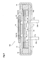
- Fig. 2 shows a partial development of the condenser microphone 100.
- Fig. 3 shows a section of the microphone 100 shown in Fig. 1 along III-III line in Fig. 1 .
- the condenser microphone 100 is formed of the respective components, namely, the switch 10, the switch circuit board 11, a diaphragm 12, a spacer 13, a back electrode 14, a gate ring 15, a drain ring 16, the signal processing circuit board 17 and the capsule 18. These components are assembled together in the form of coaxial cylinder and accommodated as such within the capsule 18 in the form of a cylindrical housing.
- the diaphragm 12 comprises a disc-shaped member having a diaphragm portion 12a and a holding portion 12b surrounding this diaphragm portion 12a.
- the diaphragm portion 12a is comprised of an electret film.
- This electret film is formed by a process involving heat-melting a material having low conductance (e.g. polymer material, silicon oxide film, etc.), causing the molten material to solidify between the opposed electrodes, with impingement of a direct current thereon, and subsequently removing the electrodes.
- the electret film thus produced is charged positively or negatively, but is maintained under the polarized state semi-permanently.
- the holding portion 12b is formed of an insulating material so as to maintain the polarized state of the electret film of the diaphragm portion 12a.
- the diaphragm 12 With the diaphragm 12 having this construction, its diaphragm portion 12a is vibrated by a sound (voice) propagated in the air, so that this sound can be collected.
- the diaphragm 12 is understood to correspond to what is defined as "a diaphragm electrode” in this invention.
- the back electrode 14 is provided in the form of a disc shape member made of a conductive material. The back electrode defines a plurality of holes 14a extending through this back electrode 14.
- the back electrode 14 is not vibrated by a sound propagated in the air, but is fixedly mounted within the cylindrical housing. This back electrode 14 is understood to correspond to what is defined as "a fixed electrode” in this invention.
- an annular spacer 13 made of an insulating material for providing electric insulation between the back electrode 14 and the holding portion 12b. Accordingly, in a space 25 between the back electrode 14 and the diaphragm portion 12a of the diaphragm 12, there is formed a dielectric gap (air gap) (see Fig. 3 ). Therefore, the back electrode 14 and the diaphragm 12 together constitute the "capacitor".
- the signal processing circuit board 17 is disposed adjacent one open side of the cylindrical housing and includes a converter circuit for converting change occurring in the capacitance of the capacitor in association with vibration of the diaphragm 12 into an electric signal and outputting this electric signal.
- the inventive condenser microphone 100 is assembled and mounted within the cylindrical housing. Therefore, this cylindrical housing includes two opposed openings.
- the signal processing circuit board 17 is disposed adjacent one of the openings provided in the cylindrical housing. Preferably, this opening is the one adjacent the back electrode 14 as shown in Fig. 2 and Fig. 3 . As will be described later, this arrangement is provided for transmitting electric signals from the back electrode 14 to the signal processing circuit board 17.
- the converter circuit is constructed of such components as an FET (field effect transistor), a resistor, a capacitor, etc. As this circuit per se is well-known, explanation thereof will be omitted.
- the back electrode 14 and the diaphragm 12 together constitute a "capacitor" as described above.
- the diaphragm 12 (diaphragm portion 12a) is vibrated by a sound propagating in the air.
- this causes a change in the capacitance of the capacitor. That is, the capacitance of the capacitor varies according to the sound collected by the condenser microphone 100.
- This capacitance is transmitted from the back electrode 14 via the gate ring 15 to the converter circuit included in the signal processing circuit board 17 and then the converter circuit converts this capacitance (change in the capacitance) transmitted from the capacitor into an electric signal.
- the gate ring 15 is disposed between the capacitor and the signal processing circuit board 17 and establishes electric conduction between the capacitor and the signal processing circuit board 17.
- the "capacitor” refers to the above capacitor constituted from the back electrode 14 and the diaphragm 12. Therefore, as shown in Fig. 2 and Fig. 3 , the gate ring 15 is disposed between the back electrode 14 and the signal processing circuit board 17. Further, the gate ring 15 is provided in the form of an annular member made of conductive material. Thus, change in the capacitance can be transmitted from the back electrode 14 to the signal processing circuit board 17.
- the switch circuit board 11 is disposed adjacent the opening portion of the cylindrical housing and includes the switch 10 for controlling operation of the converter circuit.
- the condenser microphone 100 according to the present invention is assembled and mounted within the cylindrical housing, and adjacent one of the openings of this cylindrical housing, the signal processing circuit board 17 is disposed.
- the switch circuit board 11 is disposed adjacent the other opening of the cylindrical housing, namely, on the side of the opening opposite to the opening where the signal processing circuit board 17. Therefore, the opening where the switch circuit board 11 is disposed corresponds to the opening adjacent the diaphragm 12 as shown in Fig. 2 and Fig. 3 .
- this arrangement is provided for facilitating a depressing operation of a switch button 30 included in the switch 10.
- the switch 10 is provided with a wire patterning so as to function as a single-pole, opening/closing switch.
- the opening/closing switch is closed.
- the opening/closing switch is opened.
- This opened state renders the converter circuit operable and the closed state renders the converter circuit inoperable. Therefore, the user can effect a desired operation by depressing the switch button 30.
- the drain ring 16 is disposed between the switch circuit board 11 and the signal processing circuit board 17 and is configured to transmit a switch signal corresponding to an operation on the switch 10 (switch button 30) to the signal processing circuit board 17.
- the switch button 30 will be depressed by a user, in the course of which a switch signal corresponding to the opened/closed state of the switch 10 will be outputted.
- a switch signal for rendering the converter circuit operable is outputted in the case of the opened state.
- a switch signal for rendering the converter circuit inoperable is outputted.
- the drain ring 16 is provided as an annular member made of a conductive material and is disposed and clamped between the signal processing circuit board 17 and the switch circuit board 11. Therefore, the switch signals can be transmitted in favorable manner from the switch circuit board 11 to the signal processing circuit board 17.
- the gate ring 15 and the drain ring 16 are both formed as cylindrical components, with the outer diameter of the gate ring 15 being smaller than the inner diameter of the drain ring 16.
- the respective components constituting the condenser microphone 100 are formed coaxially cylindrical. Therefore, the gate ring 15 and the drain ring 16 too are formed coaxially cylindrical.
- the respective inner and outer diameters are set such that the gate ring 15 can be contained at the center portion of the drain ring 16 (the center portion of the cylinder formed by the drain ring 16) as shown in Fig. 2 and Fig. 3 .
- an insulating material 16a for providing insulation between the gate ring 15 and the drain ring 16.
- the capsule 18 is formed as a cylindrical body made of an insulating material. This capsule 18 is configured so as to surround the outermost periphery of the cylinders constituting the switch 10, the switch circuit board 11, the diaphragm 12, the spacer 13, the back electrode 14, the gate ring 15, the drain ring 16 and the signal processing circuit board 17 described above. Therefore, these respective components can be protected electrically and mechanically by the capsule 18.
- the condenser microphone 100 is constructed as described above. In the following discussion, there will be described an arrangement wherein the switch button 30 is added to the condenser microphone 100.
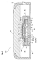
- Fig. 4 shows a section of a condenser microphone unit 200 comprising the condenser microphone 100 and the switch button 30 added thereto.
- the condenser microphone 100 is supported with insertion of the pair of pin connectors 20a, 20b into a pair of holes formed in a main circuit board 60. Further, on the upper face of the switch 10, the switch button 30 is mounted. And, a cover member 70 formed of e.g. a resin is provided for covering the lateral side so as to accommodate the condenser microphone 100 together with the switch button 30 and the main circuit board 60. Therefore, the condenser microphone 100, the switch button 30, the main circuit board 60 and the cover member 70 together form a space 90 therebetween.
- a cover member 70 formed of e.g. a resin
- the cover member 70 includes, in its lateral face, an opening 71 for providing communication between the space 90 described above and the outside.
- This opening 71 is provided as a hole having a predetermined inner diameter to function as a window for introducing a sound vibration.
- an opening 62 can be provided also in the main circuit board 60. With this provision of the opening 62 in the main circuit board 60, it is possible to reduce the directional characteristic for introducing the sound vibration.
- a sound hole 80 for introducing the vibration applied to the diaphragm 12.
- this sound hole 80 is formed perpendicularly upward of at least the diaphragm portion 12a of the diaphragm 12.
- the vibration can be transmitted in a favorable manner to the diaphragm 12.
- a sound (vibration) which has been propagated in the air will reach the diaphragm 12 along a broken line A shown in Fig. 4 . More particularly, the sound will reach the diaphragm 12 through the opening 71 (or opening 62), the space 90, a communication hole 91 between the switch 10 and the switch circuit board 11 and the sound hole 80. Therefore, the diaphragm portion 12a will be vibrated by this transmitted sound, so that the condenser microphone 100 can detect a change in the capacitance effectively.
- the sound hole 80 formed in the switch circuit board 11 is formed preferably perpendicularly upward of at least the diaphragm portion 12a of the diaphragm 12.
- the present invention is not limited thereto. It is a matter of course that the sound hole 80 can be formed at any other portion than the position perpendicularly upward of the diaphragm portion 12a of the diaphragm 12.
- the sound hole 81 for introducing vibration applied to the diaphragm 12 in the signal processing circuit board 17.
- the sound (vibration) which has been propagated in the air will reach the diaphragm 12 along a broken line B shown in Fig. 4 . More particularly, the sound will reach the diaphragm 12 through the opening 62, the sound hole 81, the hole 14a formed in the back electrode 14. With this arrangement, sound collection can be carried out in a favorable manner. Further alternatively, by providing only the opening 62, not providing the opening 71, it becomes possible to make the opening 62 less conspicuous. So, the deterioration of the aesthetic of the product can be avoided.
- one of the pin connectors 20a, 20b is an output terminal and the other is a GND terminal.
- the present invention is not limited thereto. It is needless to say that without using the pin connectors 20a, 20b, surface-mounted type electrodes (lands 20c, 20d) can also be used as shown in Fig. 5 .
- the condenser microphone 100 has the microphone function.
- the present invention is not limited thereto. Needless to say, the invention can be applied also to one having an earphone function.
- an electret film is formed in the diaphragm portion 12a.
- the present invention is not limited thereto.
- an electret film may be formed (electrically charged) to a film laminated on the back electrode 14.
- the present invention may be applied to a condenser microphone configured to convert into an electric signal a change in capacitance of a capacitor comprised of a diaphragm electrode and a fixed electrode.
Abstract
Description
- The present invention relates to a condenser microphone configured to convert a change in capacitance of a capacitor comprised of a diaphragm electrode and a fixed electrode into an electric signal.
- Conventionally, when an audio signal is transmitted between a mobile computer (or phone) and an earphone or a speaker, the method widely employed for this purpose is using a cable for connecting the mobile computer (or phone) to the earphone or speaker. With an earphone set or speaker set produced with using this method, the earphone or speaker is connected to one end of the cable and a plug to be inserted into a jack of the mobile computer (or phone) is connected to the other end of the cable. One exemplary technique relating to such earphone or speaker set as above is disclosed in
U.S. Patent Application Publication Serial No. 2008/0166003 . - The technique disclosed in
U.S. Patent Application Publication Serial No. 2008/0166003 concerns a headset having an earphone connected to one end of a cable and a plug connected to the other end of the cable. With this headset, there is also provided a switch between the earphone and the plug and a switch mechanism (e.g. a switch button) is mounted on a circuit board provided separately from a microphone constituting the earphone. Thus, the construction requires the circuit board for mounting the switch mechanism, thus leading to enlargement of the switch mechanism, which presents in turn a problem in portability. Further, if a clip or the like is to be provided to the switch mechanism for allowing this mechanism to be hooked to a piece of clothes, this would result in further enlargement of the switch mechanism. And, if a clip or the like is to be provided to the microphone also, providing the clips or the like to the microphone and the switch mechanism separately would cause disadvantageous cost increase. - The present invention has been made in view of the above-described state of the art. Its principal object is to provide a condenser microphone that has improved portability and that can be realized at low costs.
- For accomplishing the above-noted object, a condenser microphone, according to the present invention, comprises, as all being accommodated within a cylindrical housing:
- a capacitor including a diaphragm electrode and a fixed electrode;
- a signal processing circuit board disposed at one opening of the cylindrical housing and having a converter circuit for converting a change in capacitance of the capacitor which has occurred in association with vibration of the diaphragm electrode into an electric signal and outputting this electric signal;
- a gate ring disposed between the capacitor and the signal processing circuit board for establishing electric conduction therebetween;
- a switch circuit board disposed at the other opening of the cylindrical housing and having a switch for controlling operation of the converter circuit; and
- a drain ring disposed between the switch circuit board and the signal processing circuit board for transmitting a switch signal according to an operation of the switch to the signal processing circuit board.
- With the above-described construction, by using the drain ring, a switch signal relating to a switch operation can be transmitted in a favorable manner to the signal processing circuit board. Therefore, even after the condenser microphone has been packaged within a predetermined housing or box, its operational condition can be controlled with the switch. Further, with the above construction provided by the present invention, the condenser microphone and the switch can be provided in a single package. So, a condenser microphone having improved portability can be realized. Furthermore, the single package construction allows for co-use of the housing. And, when a clip is to be provided, this clip too can be co-used. As a result, the condenser microphone can be realized at low costs.
- Preferably, the gate ring has an outer diameter smaller than an inner diameter of the drain ring.
- With the above arrangement, the gate ring and the drain ring can be provided in the form of a double-layered cylindrical construction. Therefore, the electric connections between the signal processing circuit board and the switch and between the capacitor and the signal processing circuit board can be realized in a compact manner. Thus, the portability of the condenser microphone can be further improved.
- Still preferably, a sound hole for introducing vibration applied to the diaphragm electrode is formed in the switch circuit board.
- With the above arrangement, sound-relating vibration can be transmitted in a favorable manner to the diaphragm electrode. Hence, sound can be effectively collected at the diaphragm electrode.
- Preferably and alternatively, a sound hole for introducing vibration applied to the diaphragm electrode is formed in the signal processing circuit board.
- With the above arrangement, the sound hole can be formed at a position less conspicuous. Thus, it is possible to prevent the presence of the sound hole impairing the aesthetic. Further, in particular, when sound holes are used in both the switch circuit board and the signal processing board, the holes can be used in reversible manner.
-
-
Fig. 1 shows an outer shape of a condenser microphone, -
Fig. 2 is a development view of the condenser microphone, -
Fig. 3 is a section taken along a III-III line inFig. 1 , -
Fig. 4 shows an assembled condition of the condenser microphone, and -
Fig. 5 is a view showing electrodes relating to a further embodiment. - Next, preferred embodiments of the present invention will be described with reference to the accompanying drawings. A
condenser microphone 100 of the invention, though will be detailed later, is formed compact with inclusion of aswitch 10 for controlling operations of thiscondenser microphone 100.Fig. 1 (a) is a perspective view showing the front surface of thecondenser microphone 100 relating to the present embodiment.Fig. 1 (b) is a perspective view showing the back surface of thecondenser microphone 100. - As shown in
Fig. 1 , thecondenser microphone 100 has its periphery surrounded by acylindrical capsule 18 with opposed open ends. On the side of one open end of thiscylindrical capsule 18, there is provided a switch circuit board 11 (seeFig. 1 (a) ) and at the side of the other open end of thecylindrical capsule 18, there is provided a signal processing circuit board 17 (seeFig. 1 (b) ). The signalprocessing circuit board 17 defines throughholes pin connectors - The
switch circuit board 11, though will be detailed later, mounts theswitch 10 for controlling the operations of thecondenser microphone 100, with theswitch 10 being mounted with a predetermined gap relative to thisswitch circuit board 11. Incidentally, thisswitch 10 is shown schematically for its wiring pattern only inFig. 1 (a) . In fact, theswitch 10 will be formed with a switch button 30 (described later) disposed vertically upward of the wiring pattern. Further, the signalprocessing circuit board 17 includes a sound hole 81 (described later) as shown inFig. 1 (b) . - Of the pair of
pin connectors condenser microphone 100 and the other acts as a GND terminal. In the case of a construction where the condenser microphone 100 is configured like a microphone to output a collected sound in the form of a sound signal to an externally connected device, one of the pair ofpin connectors condenser microphone 100 is configured like an earphone to receive an audio signal transmitted from an externally connected device, one of the pair ofpin connectors pin connectors condenser microphone 100 will be described as being configured like a microphone for collecting sound from the outside. -
Fig. 2 shows a partial development of thecondenser microphone 100. And,Fig. 3 shows a section of themicrophone 100 shown inFig. 1 along III-III line inFig. 1 . The following discussion will be made with reference toFigs. 2 and3 . Thecondenser microphone 100 is formed of the respective components, namely, theswitch 10, theswitch circuit board 11, adiaphragm 12, aspacer 13, aback electrode 14, agate ring 15, adrain ring 16, the signalprocessing circuit board 17 and thecapsule 18. These components are assembled together in the form of coaxial cylinder and accommodated as such within thecapsule 18 in the form of a cylindrical housing. - The
diaphragm 12 comprises a disc-shaped member having adiaphragm portion 12a and a holdingportion 12b surrounding thisdiaphragm portion 12a. In the instant embodiment, thediaphragm portion 12a is comprised of an electret film. This electret film is formed by a process involving heat-melting a material having low conductance (e.g. polymer material, silicon oxide film, etc.), causing the molten material to solidify between the opposed electrodes, with impingement of a direct current thereon, and subsequently removing the electrodes. The electret film thus produced is charged positively or negatively, but is maintained under the polarized state semi-permanently. - The holding
portion 12b is formed of an insulating material so as to maintain the polarized state of the electret film of thediaphragm portion 12a. With thediaphragm 12 having this construction, itsdiaphragm portion 12a is vibrated by a sound (voice) propagated in the air, so that this sound can be collected. Here, thediaphragm 12 is understood to correspond to what is defined as "a diaphragm electrode" in this invention. Further, theback electrode 14 is provided in the form of a disc shape member made of a conductive material. The back electrode defines a plurality ofholes 14a extending through thisback electrode 14. Theback electrode 14 is not vibrated by a sound propagated in the air, but is fixedly mounted within the cylindrical housing. Thisback electrode 14 is understood to correspond to what is defined as "a fixed electrode" in this invention. - And, between the
back electrode 14 and thediaphragm 12, there is disposed anannular spacer 13 made of an insulating material for providing electric insulation between theback electrode 14 and the holdingportion 12b. Accordingly, in aspace 25 between theback electrode 14 and thediaphragm portion 12a of thediaphragm 12, there is formed a dielectric gap (air gap) (seeFig. 3 ). Therefore, theback electrode 14 and thediaphragm 12 together constitute the "capacitor". - The signal
processing circuit board 17 is disposed adjacent one open side of the cylindrical housing and includes a converter circuit for converting change occurring in the capacitance of the capacitor in association with vibration of thediaphragm 12 into an electric signal and outputting this electric signal. As described above, theinventive condenser microphone 100 is assembled and mounted within the cylindrical housing. Therefore, this cylindrical housing includes two opposed openings. And, the signalprocessing circuit board 17 is disposed adjacent one of the openings provided in the cylindrical housing. Preferably, this opening is the one adjacent theback electrode 14 as shown inFig. 2 andFig. 3 . As will be described later, this arrangement is provided for transmitting electric signals from theback electrode 14 to the signalprocessing circuit board 17. Further, the converter circuit is constructed of such components as an FET (field effect transistor), a resistor, a capacitor, etc. As this circuit per se is well-known, explanation thereof will be omitted. - Here, the
back electrode 14 and thediaphragm 12 together constitute a "capacitor" as described above. Further, the diaphragm 12 (diaphragm portion 12a) is vibrated by a sound propagating in the air. Hence, as thediaphragm portion 12a is vibrated by a sound, this causes a change in the capacitance of the capacitor. That is, the capacitance of the capacitor varies according to the sound collected by thecondenser microphone 100. This capacitance is transmitted from theback electrode 14 via thegate ring 15 to the converter circuit included in the signalprocessing circuit board 17 and then the converter circuit converts this capacitance (change in the capacitance) transmitted from the capacitor into an electric signal. - The
gate ring 15 is disposed between the capacitor and the signalprocessing circuit board 17 and establishes electric conduction between the capacitor and the signalprocessing circuit board 17. Here, the "capacitor" refers to the above capacitor constituted from theback electrode 14 and thediaphragm 12. Therefore, as shown inFig. 2 andFig. 3 , thegate ring 15 is disposed between theback electrode 14 and the signalprocessing circuit board 17. Further, thegate ring 15 is provided in the form of an annular member made of conductive material. Thus, change in the capacitance can be transmitted from theback electrode 14 to the signalprocessing circuit board 17. - The
switch circuit board 11 is disposed adjacent the opening portion of the cylindrical housing and includes theswitch 10 for controlling operation of the converter circuit. As described above, thecondenser microphone 100 according to the present invention is assembled and mounted within the cylindrical housing, and adjacent one of the openings of this cylindrical housing, the signalprocessing circuit board 17 is disposed. And, theswitch circuit board 11 is disposed adjacent the other opening of the cylindrical housing, namely, on the side of the opening opposite to the opening where the signalprocessing circuit board 17. Therefore, the opening where theswitch circuit board 11 is disposed corresponds to the opening adjacent thediaphragm 12 as shown inFig. 2 andFig. 3 . As will be detailed later, this arrangement is provided for facilitating a depressing operation of aswitch button 30 included in theswitch 10. - The
switch 10 is provided with a wire patterning so as to function as a single-pole, opening/closing switch. In response to a depressing operation on theunillustrated switch button 30, the opening/closing switch is closed. In response to a further depressing operation, the opening/closing switch is opened. This opened state renders the converter circuit operable and the closed state renders the converter circuit inoperable. Therefore, the user can effect a desired operation by depressing theswitch button 30. Needless to say, it is also possible to employ a different opening/closing switch which is rendered into the closed state only while the user keeps depressing it. That is, a terminal corresponding to the wire patterning as the above-described single-pole opening/closing switch is connected to theswitch circuit board 11. Therefore, the closed state and the opened state of theswitch 10 can be identified on the side of theswitch circuit board 11. - The
drain ring 16 is disposed between theswitch circuit board 11 and the signalprocessing circuit board 17 and is configured to transmit a switch signal corresponding to an operation on the switch 10 (switch button 30) to the signalprocessing circuit board 17. Here, theswitch button 30 will be depressed by a user, in the course of which a switch signal corresponding to the opened/closed state of theswitch 10 will be outputted. For instance, in the case of the closed state, a switch signal for rendering the converter circuit operable is outputted. In the case of the opened state, a switch signal for rendering the converter circuit inoperable is outputted. Thedrain ring 16 is provided as an annular member made of a conductive material and is disposed and clamped between the signalprocessing circuit board 17 and theswitch circuit board 11. Therefore, the switch signals can be transmitted in favorable manner from theswitch circuit board 11 to the signalprocessing circuit board 17. - Here, the
gate ring 15 and thedrain ring 16 are both formed as cylindrical components, with the outer diameter of thegate ring 15 being smaller than the inner diameter of thedrain ring 16. As described hereinbefore, the respective components constituting thecondenser microphone 100 are formed coaxially cylindrical. Therefore, thegate ring 15 and thedrain ring 16 too are formed coaxially cylindrical. Further, the respective inner and outer diameters are set such that thegate ring 15 can be contained at the center portion of the drain ring 16 (the center portion of the cylinder formed by the drain ring 16) as shown inFig. 2 andFig. 3 . Incidentally, at the inner peripheral portion of thedrain ring 16, there is formed an insulatingmaterial 16a for providing insulation between thegate ring 15 and thedrain ring 16. - The
capsule 18 is formed as a cylindrical body made of an insulating material. Thiscapsule 18 is configured so as to surround the outermost periphery of the cylinders constituting theswitch 10, theswitch circuit board 11, thediaphragm 12, thespacer 13, theback electrode 14, thegate ring 15, thedrain ring 16 and the signalprocessing circuit board 17 described above. Therefore, these respective components can be protected electrically and mechanically by thecapsule 18. - The
condenser microphone 100 is constructed as described above. In the following discussion, there will be described an arrangement wherein theswitch button 30 is added to thecondenser microphone 100.Fig. 4 shows a section of acondenser microphone unit 200 comprising thecondenser microphone 100 and theswitch button 30 added thereto. Thecondenser microphone 100 is supported with insertion of the pair ofpin connectors main circuit board 60. Further, on the upper face of theswitch 10, theswitch button 30 is mounted. And, acover member 70 formed of e.g. a resin is provided for covering the lateral side so as to accommodate thecondenser microphone 100 together with theswitch button 30 and themain circuit board 60. Therefore, thecondenser microphone 100, theswitch button 30, themain circuit board 60 and thecover member 70 together form aspace 90 therebetween. - The
cover member 70 includes, in its lateral face, anopening 71 for providing communication between thespace 90 described above and the outside. Thisopening 71 is provided as a hole having a predetermined inner diameter to function as a window for introducing a sound vibration. Further, anopening 62 can be provided also in themain circuit board 60. With this provision of theopening 62 in themain circuit board 60, it is possible to reduce the directional characteristic for introducing the sound vibration. - Preferably, in the
switch circuit board 11, there is formed asound hole 80 for introducing the vibration applied to thediaphragm 12. Preferably, thissound hole 80 is formed perpendicularly upward of at least thediaphragm portion 12a of thediaphragm 12. By forming thesound hole 80 at such position as above, the vibration can be transmitted in a favorable manner to thediaphragm 12. A sound (vibration) which has been propagated in the air will reach thediaphragm 12 along a broken line A shown inFig. 4 . More particularly, the sound will reach thediaphragm 12 through the opening 71 (or opening 62), thespace 90, acommunication hole 91 between theswitch 10 and theswitch circuit board 11 and thesound hole 80. Therefore, thediaphragm portion 12a will be vibrated by this transmitted sound, so that thecondenser microphone 100 can detect a change in the capacitance effectively. - In the foregoing embodiment, it was explained that the
sound hole 80 formed in theswitch circuit board 11 is formed preferably perpendicularly upward of at least thediaphragm portion 12a of thediaphragm 12. However, the present invention is not limited thereto. It is a matter of course that thesound hole 80 can be formed at any other portion than the position perpendicularly upward of thediaphragm portion 12a of thediaphragm 12. - Further, as shown in
Fig. 4 , it is also possible as a matter of course to form thesound hole 81 for introducing vibration applied to thediaphragm 12 in the signalprocessing circuit board 17. The sound (vibration) which has been propagated in the air will reach thediaphragm 12 along a broken line B shown inFig. 4 . More particularly, the sound will reach thediaphragm 12 through theopening 62, thesound hole 81, thehole 14a formed in theback electrode 14. With this arrangement, sound collection can be carried out in a favorable manner. Further alternatively, by providing only theopening 62, not providing theopening 71, it becomes possible to make theopening 62 less conspicuous. So, the deterioration of the aesthetic of the product can be avoided. - In the foregoing embodiment, it was explained that one of the
pin connectors pin connectors lands Fig. 5 . - In the foregoing embodiment, it was explained that the
condenser microphone 100 has the microphone function. However, the present invention is not limited thereto. Needless to say, the invention can be applied also to one having an earphone function. - In the foregoing embodiment, it was explained that an electret film is formed in the
diaphragm portion 12a. However, the present invention is not limited thereto. For instance, it is needless to say that an electret film may be formed (electrically charged) to a film laminated on theback electrode 14. - The present invention may be applied to a condenser microphone configured to convert into an electric signal a change in capacitance of a capacitor comprised of a diaphragm electrode and a fixed electrode.
-
- 10: switch
- 11: switch circuit board
- 12: diaphragm (diaphragm electrode)
- 12a: diaphragm portion
- 12b: holding portion
- 13: spacer
- 14: back electrode (fixed electrode)
- 14a: hole
- 15: gate ring
- 16: drain ring
- 16a: insulating material
- 17: signal processing circuit board
- 18: capsule (cylindrical housing)
- 20a: pin connector
- 20b: pin connector
- 80: sound hole
- 81: sound hole
- 100: condenser microphone
Claims (4)
- A condenser microphone (100), comprising, as all being accommodated within a cylindrical housing (18):characterized by
a capacitor including a diaphragm electrode (12) and a fixed electrode (14);
a signal processing circuit board (17) disposed at one opening of the cylindrical housing (18) and having a converter circuit for converting a change in capacitance of the capacitor which has occurred in association with vibration of the diaphragm electrode (12) into an electric signal and outputting this electric signal;
a gate ring (15) disposed between the capacitor and the signal processing circuit board (17) for establishing electric conduction therebetween;
a switch circuit board (11) disposed at the other opening of the cylindrical housing (18) and having a switch (10) for controlling operation of the converter circuit; and
a drain ring (16) disposed between the switch circuit board (11) and the signal processing circuit board (17) for transmitting a switch signal according to an operation of the switch (10) to the signal processing circuit board (17). - The condenser microphone (100) according to claim 1, characterized in that the gate ring (15) has an outer diameter smaller than an inner diameter of the drain ring (16).
- The condenser microphone (100) according to claim 1 or 2, characterized in that a sound hole (80) for introducing vibration applied to the diaphragm electrode (12) is formed in the switch circuit board (11).
- The condenser microphone (100) according to any one of claims 1-3, characterized in that a sound hole (81) for introducing vibration applied to the diaphragm electrode (12) is formed in the signal processing circuit board (17).
Applications Claiming Priority (1)
| Application Number | Priority Date | Filing Date | Title |
|---|---|---|---|
| JP2009158901A JP4809912B2 (en) | 2009-07-03 | 2009-07-03 | Condenser microphone |
Publications (3)
| Publication Number | Publication Date |
|---|---|
| EP2271135A2 true EP2271135A2 (en) | 2011-01-05 |
| EP2271135A3 EP2271135A3 (en) | 2013-06-19 |
| EP2271135B1 EP2271135B1 (en) | 2015-01-28 |
Family
ID=42830059
Family Applications (1)
| Application Number | Title | Priority Date | Filing Date |
|---|---|---|---|
| EP10005829.6A Not-in-force EP2271135B1 (en) | 2009-07-03 | 2010-06-05 | Condenser microphone |
Country Status (7)
| Country | Link |
|---|---|
| US (1) | US8391531B2 (en) |
| EP (1) | EP2271135B1 (en) |
| JP (1) | JP4809912B2 (en) |
| KR (1) | KR101051603B1 (en) |
| CN (1) | CN101945319B (en) |
| DK (1) | DK2271135T3 (en) |
| TW (1) | TWI433551B (en) |
Cited By (1)
| Publication number | Priority date | Publication date | Assignee | Title |
|---|---|---|---|---|
| WO2021155901A1 (en) * | 2020-02-03 | 2021-08-12 | Huawei Technologies Co., Ltd. | Wireless headset with improved wind noise resistance |
Families Citing this family (4)
| Publication number | Priority date | Publication date | Assignee | Title |
|---|---|---|---|---|
| USD743382S1 (en) * | 2013-09-20 | 2015-11-17 | Panasonic Intellectual Property Management Co., Ltd. | Microphone |
| JP6677694B2 (en) * | 2017-10-31 | 2020-04-08 | ファナック株式会社 | Robot system |
| DE102018203098B3 (en) * | 2018-03-01 | 2019-06-19 | Infineon Technologies Ag | MEMS sensor |
| JP7196798B2 (en) * | 2019-08-09 | 2022-12-27 | 株式会社Soken | ultrasonic sensor |
Citations (1)
| Publication number | Priority date | Publication date | Assignee | Title |
|---|---|---|---|---|
| US20080166003A1 (en) | 2007-01-06 | 2008-07-10 | Apple Inc. | Wire headset with integrated switch |
Family Cites Families (25)
| Publication number | Priority date | Publication date | Assignee | Title |
|---|---|---|---|---|
| US3005055A (en) * | 1957-10-08 | 1961-10-17 | Bell Telephone Labor Inc | Tilting dial circuit selector |
| US3743784A (en) * | 1971-11-19 | 1973-07-03 | Olympus Optical Co | Electrical attachment device |
| DE69233156T2 (en) * | 1991-01-17 | 2004-07-08 | Adelman, Roger A. | IMPROVED HEARING AID |
| JPH04257200A (en) * | 1991-02-12 | 1992-09-11 | Matsushita Electric Ind Co Ltd | Electret capacitor microphone |
| US5224474A (en) * | 1991-03-04 | 1993-07-06 | Bloomfield John W | Retrofitting gas mask voice amplifier unit with easily actuated switch means |
| KR20000012476A (en) * | 1999-12-07 | 2000-03-06 | 김종규 | Condenser microphone |
| CN2448032Y (en) * | 2000-09-08 | 2001-09-12 | 葛清华 | Microphone self-switching microphone device with hand-free receiver |
| JP3908059B2 (en) * | 2002-02-27 | 2007-04-25 | スター精密株式会社 | Electret condenser microphone |
| JP3919609B2 (en) * | 2002-06-20 | 2007-05-30 | 株式会社オーディオテクニカ | Condenser microphone |
| JP4033830B2 (en) * | 2002-12-03 | 2008-01-16 | ホシデン株式会社 | Microphone |
| KR100509560B1 (en) * | 2003-03-12 | 2005-08-23 | 주식회사 비에스이 | Eletret condenser microphone framing |
| KR200330089Y1 (en) * | 2003-07-29 | 2003-10-11 | 주식회사 비에스이 | Integrated base and electret condenser microphone using the same |
| JP2005130437A (en) * | 2003-10-24 | 2005-05-19 | Knowles Electronics Llc | High-performance capacitor microphone and its manufacturing method |
| KR100556684B1 (en) * | 2004-01-20 | 2006-03-10 | 주식회사 비에스이 | A condenser microphone mountable on main PCB |
| CN1671252A (en) * | 2004-03-16 | 2005-09-21 | 美商楼氏电子有限公司 | High-performance capacitor microphone and its manufacturing method |
| US7349551B2 (en) * | 2004-09-03 | 2008-03-25 | Ultra Electronics Audiopack, Inc. | Lapel microphone with push to talk switch |
| KR100675510B1 (en) * | 2005-04-25 | 2007-01-30 | 주식회사 비에스이 | Dual base and electret condenser microphone using the same |
| KR100675505B1 (en) * | 2005-04-29 | 2007-01-30 | 주식회사 비에스이 | Case for condenser microphone |
| JP4683996B2 (en) | 2005-05-06 | 2011-05-18 | 株式会社オーディオテクニカ | Condenser microphone |
| JP4150407B2 (en) * | 2005-06-20 | 2008-09-17 | ホシデン株式会社 | Electroacoustic transducer |
| JP2007005913A (en) * | 2005-06-21 | 2007-01-11 | Hosiden Corp | Electrostatic electroacoustic transducer |
| KR100758838B1 (en) * | 2006-02-24 | 2007-09-14 | 주식회사 비에스이 | A square condenser microphone |
| WO2008046175A1 (en) * | 2006-10-20 | 2008-04-24 | Con-Space Communications Ltd. | Throat microphone assembly and communications assembly |
| JP4328347B2 (en) * | 2006-11-10 | 2009-09-09 | ホシデン株式会社 | Microphone and its mounting structure |
| CN101466059B (en) * | 2007-12-17 | 2012-06-20 | 鸿富锦精密工业(深圳)有限公司 | Capacitance type microphone |
-
2009
- 2009-07-03 JP JP2009158901A patent/JP4809912B2/en not_active Expired - Fee Related
-
2010
- 2010-06-04 TW TW099118148A patent/TWI433551B/en not_active IP Right Cessation
- 2010-06-05 DK DK10005829.6T patent/DK2271135T3/en active
- 2010-06-05 EP EP10005829.6A patent/EP2271135B1/en not_active Not-in-force
- 2010-06-07 KR KR1020100053487A patent/KR101051603B1/en active IP Right Grant
- 2010-06-16 US US12/816,615 patent/US8391531B2/en active Active
- 2010-07-02 CN CN2010102234212A patent/CN101945319B/en not_active Expired - Fee Related
Patent Citations (1)
| Publication number | Priority date | Publication date | Assignee | Title |
|---|---|---|---|---|
| US20080166003A1 (en) | 2007-01-06 | 2008-07-10 | Apple Inc. | Wire headset with integrated switch |
Cited By (3)
| Publication number | Priority date | Publication date | Assignee | Title |
|---|---|---|---|---|
| WO2021155901A1 (en) * | 2020-02-03 | 2021-08-12 | Huawei Technologies Co., Ltd. | Wireless headset with improved wind noise resistance |
| CN115004717A (en) * | 2020-02-03 | 2022-09-02 | 华为技术有限公司 | Wireless headset with higher wind noise resistance |
| CN115004717B (en) * | 2020-02-03 | 2023-08-04 | 华为技术有限公司 | Wireless headset with higher wind noise resistance |
Also Published As
| Publication number | Publication date |
|---|---|
| JP4809912B2 (en) | 2011-11-09 |
| DK2271135T3 (en) | 2015-03-02 |
| TWI433551B (en) | 2014-04-01 |
| KR101051603B1 (en) | 2011-07-22 |
| JP2011015282A (en) | 2011-01-20 |
| US8391531B2 (en) | 2013-03-05 |
| US20110002483A1 (en) | 2011-01-06 |
| CN101945319B (en) | 2013-08-21 |
| CN101945319A (en) | 2011-01-12 |
| EP2271135A3 (en) | 2013-06-19 |
| EP2271135B1 (en) | 2015-01-28 |
| KR20110003254A (en) | 2011-01-11 |
| TW201130325A (en) | 2011-09-01 |
Similar Documents
| Publication | Publication Date | Title |
|---|---|---|
| EP2116099B1 (en) | Wired headset with integrated switch | |
| US8391531B2 (en) | Condenser microphone | |
| KR20210036846A (en) | Sound transducer unit for generating and/or detecting sound waves in the audible wavelength spectrum and/or in the ultrasonic range | |
| CN1158835C (en) | Hinge unit for earphone with current transport unit | |
| KR20200040958A (en) | Directional MEMS microphone and MEMS microphone module comprising it | |
| CN109068250B (en) | Microphone and electronic equipment | |
| US6909613B2 (en) | Assembly comprising an electrical element | |
| JP2010161738A (en) | Non-directional condenser microphone unit and non-directional condenser microphone | |
| JPS5843335Y2 (en) | composite speaker | |
| JP3856665B2 (en) | Microphone holder | |
| KR200216321Y1 (en) | Earphone with microphone | |
| TWI597988B (en) | Wired headset with integrated switch | |
| KR200397341Y1 (en) | earphone connector for a mobile telephone | |
| KR101167912B1 (en) | Earphone | |
| KR200252660Y1 (en) | Earmic with flip | |
| AU2011232790B2 (en) | Wired headset with integrated switch | |
| KR20160101746A (en) | Connecting member and assembling structure with connecting member | |
| KR200363850Y1 (en) | Digital Recording Stethoscope | |
| KR200189848Y1 (en) | Multi-connecter for computer | |
| KR19980018880U (en) | Microphone mounting structure of the monitor | |
| JP2002042988A (en) | Pin plug, radio telephone terminal and adaptor device | |
| KR19980066473U (en) | Multifunction plug | |
| KR20050086143A (en) | Wire to board connector | |
| KR20020064863A (en) | Internetphone Speaker | |
| KR19980018863U (en) | Microphone mounting structure of the monitor |
Legal Events
| Date | Code | Title | Description |
|---|---|---|---|
| PUAI | Public reference made under article 153(3) epc to a published international application that has entered the european phase |
Free format text: ORIGINAL CODE: 0009012 |
|
| AK | Designated contracting states |
Kind code of ref document: A2 Designated state(s): AL AT BE BG CH CY CZ DE DK EE ES FI FR GB GR HR HU IE IS IT LI LT LU LV MC MK MT NL NO PL PT RO SE SI SK SM TR |
|
| AX | Request for extension of the european patent |
Extension state: BA ME RS |
|
| PUAL | Search report despatched |
Free format text: ORIGINAL CODE: 0009013 |
|
| AK | Designated contracting states |
Kind code of ref document: A3 Designated state(s): AL AT BE BG CH CY CZ DE DK EE ES FI FR GB GR HR HU IE IS IT LI LT LU LV MC MK MT NL NO PL PT RO SE SI SK SM TR |
|
| AX | Request for extension of the european patent |
Extension state: BA ME RS |
|
| RIC1 | Information provided on ipc code assigned before grant |
Ipc: H01H 13/00 20060101ALI20130515BHEP Ipc: H04R 1/10 20060101ALI20130515BHEP Ipc: H04R 19/04 20060101AFI20130515BHEP |
|
| 17P | Request for examination filed |
Effective date: 20130918 |
|
| RBV | Designated contracting states (corrected) |
Designated state(s): AL AT BE BG CH CY CZ DE DK EE ES FI FR GB GR HR HU IE IS IT LI LT LU LV MC MK MT NL NO PL PT RO SE SI SK SM TR |
|
| REG | Reference to a national code |
Ref country code: DE Ref legal event code: R079 Ref document number: 602010022071 Country of ref document: DE Free format text: PREVIOUS MAIN CLASS: H04R0019040000 Ipc: H04R0019010000 |
|
| GRAP | Despatch of communication of intention to grant a patent |
Free format text: ORIGINAL CODE: EPIDOSNIGR1 |
|
| RIC1 | Information provided on ipc code assigned before grant |
Ipc: H04R 1/10 20060101ALI20141002BHEP Ipc: H01H 13/00 20060101ALI20141002BHEP Ipc: H04R 19/01 20060101AFI20141002BHEP |
|
| INTG | Intention to grant announced |
Effective date: 20141017 |
|
| GRAS | Grant fee paid |
Free format text: ORIGINAL CODE: EPIDOSNIGR3 |
|
| GRAA | (expected) grant |
Free format text: ORIGINAL CODE: 0009210 |
|
| AK | Designated contracting states |
Kind code of ref document: B1 Designated state(s): AL AT BE BG CH CY CZ DE DK EE ES FI FR GB GR HR HU IE IS IT LI LT LU LV MC MK MT NL NO PL PT RO SE SI SK SM TR |
|
| REG | Reference to a national code |
Ref country code: GB Ref legal event code: FG4D |
|
| REG | Reference to a national code |
Ref country code: CH Ref legal event code: EP |
|
| REG | Reference to a national code |
Ref country code: IE Ref legal event code: FG4D |
|
| REG | Reference to a national code |
Ref country code: DK Ref legal event code: T3 Effective date: 20150225 |
|
| REG | Reference to a national code |
Ref country code: AT Ref legal event code: REF Ref document number: 708671 Country of ref document: AT Kind code of ref document: T Effective date: 20150315 |
|
| REG | Reference to a national code |
Ref country code: DE Ref legal event code: R096 Ref document number: 602010022071 Country of ref document: DE Effective date: 20150319 |
|
| REG | Reference to a national code |
Ref country code: AT Ref legal event code: MK05 Ref document number: 708671 Country of ref document: AT Kind code of ref document: T Effective date: 20150128 |
|
| REG | Reference to a national code |
Ref country code: NL Ref legal event code: VDEP Effective date: 20150128 |
|
| REG | Reference to a national code |
Ref country code: LT Ref legal event code: MG4D |
|
| PG25 | Lapsed in a contracting state [announced via postgrant information from national office to epo] |
Ref country code: BG Free format text: LAPSE BECAUSE OF FAILURE TO SUBMIT A TRANSLATION OF THE DESCRIPTION OR TO PAY THE FEE WITHIN THE PRESCRIBED TIME-LIMIT Effective date: 20150428 Ref country code: HR Free format text: LAPSE BECAUSE OF FAILURE TO SUBMIT A TRANSLATION OF THE DESCRIPTION OR TO PAY THE FEE WITHIN THE PRESCRIBED TIME-LIMIT Effective date: 20150128 Ref country code: SE Free format text: LAPSE BECAUSE OF FAILURE TO SUBMIT A TRANSLATION OF THE DESCRIPTION OR TO PAY THE FEE WITHIN THE PRESCRIBED TIME-LIMIT Effective date: 20150128 Ref country code: ES Free format text: LAPSE BECAUSE OF FAILURE TO SUBMIT A TRANSLATION OF THE DESCRIPTION OR TO PAY THE FEE WITHIN THE PRESCRIBED TIME-LIMIT Effective date: 20150128 Ref country code: NO Free format text: LAPSE BECAUSE OF FAILURE TO SUBMIT A TRANSLATION OF THE DESCRIPTION OR TO PAY THE FEE WITHIN THE PRESCRIBED TIME-LIMIT Effective date: 20150428 Ref country code: FI Free format text: LAPSE BECAUSE OF FAILURE TO SUBMIT A TRANSLATION OF THE DESCRIPTION OR TO PAY THE FEE WITHIN THE PRESCRIBED TIME-LIMIT Effective date: 20150128 Ref country code: LT Free format text: LAPSE BECAUSE OF FAILURE TO SUBMIT A TRANSLATION OF THE DESCRIPTION OR TO PAY THE FEE WITHIN THE PRESCRIBED TIME-LIMIT Effective date: 20150128 |
|
| PG25 | Lapsed in a contracting state [announced via postgrant information from national office to epo] |
Ref country code: PL Free format text: LAPSE BECAUSE OF FAILURE TO SUBMIT A TRANSLATION OF THE DESCRIPTION OR TO PAY THE FEE WITHIN THE PRESCRIBED TIME-LIMIT Effective date: 20150128 Ref country code: NL Free format text: LAPSE BECAUSE OF FAILURE TO SUBMIT A TRANSLATION OF THE DESCRIPTION OR TO PAY THE FEE WITHIN THE PRESCRIBED TIME-LIMIT Effective date: 20150128 Ref country code: LV Free format text: LAPSE BECAUSE OF FAILURE TO SUBMIT A TRANSLATION OF THE DESCRIPTION OR TO PAY THE FEE WITHIN THE PRESCRIBED TIME-LIMIT Effective date: 20150128 Ref country code: GR Free format text: LAPSE BECAUSE OF FAILURE TO SUBMIT A TRANSLATION OF THE DESCRIPTION OR TO PAY THE FEE WITHIN THE PRESCRIBED TIME-LIMIT Effective date: 20150429 Ref country code: IS Free format text: LAPSE BECAUSE OF FAILURE TO SUBMIT A TRANSLATION OF THE DESCRIPTION OR TO PAY THE FEE WITHIN THE PRESCRIBED TIME-LIMIT Effective date: 20150528 Ref country code: AT Free format text: LAPSE BECAUSE OF FAILURE TO SUBMIT A TRANSLATION OF THE DESCRIPTION OR TO PAY THE FEE WITHIN THE PRESCRIBED TIME-LIMIT Effective date: 20150128 |
|
| REG | Reference to a national code |
Ref country code: DE Ref legal event code: R097 Ref document number: 602010022071 Country of ref document: DE |
|
| PG25 | Lapsed in a contracting state [announced via postgrant information from national office to epo] |
Ref country code: CZ Free format text: LAPSE BECAUSE OF FAILURE TO SUBMIT A TRANSLATION OF THE DESCRIPTION OR TO PAY THE FEE WITHIN THE PRESCRIBED TIME-LIMIT Effective date: 20150128 Ref country code: SK Free format text: LAPSE BECAUSE OF FAILURE TO SUBMIT A TRANSLATION OF THE DESCRIPTION OR TO PAY THE FEE WITHIN THE PRESCRIBED TIME-LIMIT Effective date: 20150128 Ref country code: EE Free format text: LAPSE BECAUSE OF FAILURE TO SUBMIT A TRANSLATION OF THE DESCRIPTION OR TO PAY THE FEE WITHIN THE PRESCRIBED TIME-LIMIT Effective date: 20150128 Ref country code: RO Free format text: LAPSE BECAUSE OF FAILURE TO SUBMIT A TRANSLATION OF THE DESCRIPTION OR TO PAY THE FEE WITHIN THE PRESCRIBED TIME-LIMIT Effective date: 20150128 |
|
| PLBE | No opposition filed within time limit |
Free format text: ORIGINAL CODE: 0009261 |
|
| STAA | Information on the status of an ep patent application or granted ep patent |
Free format text: STATUS: NO OPPOSITION FILED WITHIN TIME LIMIT |
|
| PG25 | Lapsed in a contracting state [announced via postgrant information from national office to epo] |
Ref country code: IT Free format text: LAPSE BECAUSE OF FAILURE TO SUBMIT A TRANSLATION OF THE DESCRIPTION OR TO PAY THE FEE WITHIN THE PRESCRIBED TIME-LIMIT Effective date: 20150128 |
|
| 26N | No opposition filed |
Effective date: 20151029 |
|
| PG25 | Lapsed in a contracting state [announced via postgrant information from national office to epo] |
Ref country code: MC Free format text: LAPSE BECAUSE OF FAILURE TO SUBMIT A TRANSLATION OF THE DESCRIPTION OR TO PAY THE FEE WITHIN THE PRESCRIBED TIME-LIMIT Effective date: 20150128 |
|
| REG | Reference to a national code |
Ref country code: CH Ref legal event code: PL |
|
| PG25 | Lapsed in a contracting state [announced via postgrant information from national office to epo] |
Ref country code: SI Free format text: LAPSE BECAUSE OF FAILURE TO SUBMIT A TRANSLATION OF THE DESCRIPTION OR TO PAY THE FEE WITHIN THE PRESCRIBED TIME-LIMIT Effective date: 20150128 Ref country code: LU Free format text: LAPSE BECAUSE OF FAILURE TO SUBMIT A TRANSLATION OF THE DESCRIPTION OR TO PAY THE FEE WITHIN THE PRESCRIBED TIME-LIMIT Effective date: 20150605 |
|
| REG | Reference to a national code |
Ref country code: IE Ref legal event code: MM4A |
|
| PG25 | Lapsed in a contracting state [announced via postgrant information from national office to epo] |
Ref country code: IE Free format text: LAPSE BECAUSE OF NON-PAYMENT OF DUE FEES Effective date: 20150605 Ref country code: CH Free format text: LAPSE BECAUSE OF NON-PAYMENT OF DUE FEES Effective date: 20150630 Ref country code: LI Free format text: LAPSE BECAUSE OF NON-PAYMENT OF DUE FEES Effective date: 20150630 |
|
| PG25 | Lapsed in a contracting state [announced via postgrant information from national office to epo] |
Ref country code: BE Free format text: LAPSE BECAUSE OF FAILURE TO SUBMIT A TRANSLATION OF THE DESCRIPTION OR TO PAY THE FEE WITHIN THE PRESCRIBED TIME-LIMIT Effective date: 20150128 |
|
| REG | Reference to a national code |
Ref country code: FR Ref legal event code: PLFP Year of fee payment: 7 |
|
| PG25 | Lapsed in a contracting state [announced via postgrant information from national office to epo] |
Ref country code: MT Free format text: LAPSE BECAUSE OF FAILURE TO SUBMIT A TRANSLATION OF THE DESCRIPTION OR TO PAY THE FEE WITHIN THE PRESCRIBED TIME-LIMIT Effective date: 20150128 |
|
| PG25 | Lapsed in a contracting state [announced via postgrant information from national office to epo] |
Ref country code: SM Free format text: LAPSE BECAUSE OF FAILURE TO SUBMIT A TRANSLATION OF THE DESCRIPTION OR TO PAY THE FEE WITHIN THE PRESCRIBED TIME-LIMIT Effective date: 20150128 Ref country code: HU Free format text: LAPSE BECAUSE OF FAILURE TO SUBMIT A TRANSLATION OF THE DESCRIPTION OR TO PAY THE FEE WITHIN THE PRESCRIBED TIME-LIMIT; INVALID AB INITIO Effective date: 20100605 |
|
| REG | Reference to a national code |
Ref country code: FR Ref legal event code: PLFP Year of fee payment: 8 |
|
| PG25 | Lapsed in a contracting state [announced via postgrant information from national office to epo] |
Ref country code: CY Free format text: LAPSE BECAUSE OF FAILURE TO SUBMIT A TRANSLATION OF THE DESCRIPTION OR TO PAY THE FEE WITHIN THE PRESCRIBED TIME-LIMIT Effective date: 20150128 |
|
| PG25 | Lapsed in a contracting state [announced via postgrant information from national office to epo] |
Ref country code: TR Free format text: LAPSE BECAUSE OF FAILURE TO SUBMIT A TRANSLATION OF THE DESCRIPTION OR TO PAY THE FEE WITHIN THE PRESCRIBED TIME-LIMIT Effective date: 20150128 |
|
| REG | Reference to a national code |
Ref country code: FR Ref legal event code: PLFP Year of fee payment: 9 |
|
| PG25 | Lapsed in a contracting state [announced via postgrant information from national office to epo] |
Ref country code: MK Free format text: LAPSE BECAUSE OF FAILURE TO SUBMIT A TRANSLATION OF THE DESCRIPTION OR TO PAY THE FEE WITHIN THE PRESCRIBED TIME-LIMIT Effective date: 20150128 Ref country code: PT Free format text: LAPSE BECAUSE OF FAILURE TO SUBMIT A TRANSLATION OF THE DESCRIPTION OR TO PAY THE FEE WITHIN THE PRESCRIBED TIME-LIMIT Effective date: 20150128 |
|
| PG25 | Lapsed in a contracting state [announced via postgrant information from national office to epo] |
Ref country code: AL Free format text: LAPSE BECAUSE OF FAILURE TO SUBMIT A TRANSLATION OF THE DESCRIPTION OR TO PAY THE FEE WITHIN THE PRESCRIBED TIME-LIMIT Effective date: 20150128 |
|
| PGFP | Annual fee paid to national office [announced via postgrant information from national office to epo] |
Ref country code: DE Payment date: 20210426 Year of fee payment: 12 Ref country code: FR Payment date: 20210621 Year of fee payment: 12 |
|
| PGFP | Annual fee paid to national office [announced via postgrant information from national office to epo] |
Ref country code: GB Payment date: 20210623 Year of fee payment: 12 Ref country code: DK Payment date: 20210623 Year of fee payment: 12 |
|
| REG | Reference to a national code |
Ref country code: DE Ref legal event code: R119 Ref document number: 602010022071 Country of ref document: DE |
|
| REG | Reference to a national code |
Ref country code: DK Ref legal event code: EBP Effective date: 20220630 |
|
| GBPC | Gb: european patent ceased through non-payment of renewal fee |
Effective date: 20220605 |
|
| PG25 | Lapsed in a contracting state [announced via postgrant information from national office to epo] |
Ref country code: FR Free format text: LAPSE BECAUSE OF NON-PAYMENT OF DUE FEES Effective date: 20220630 |
|
| PG25 | Lapsed in a contracting state [announced via postgrant information from national office to epo] |
Ref country code: GB Free format text: LAPSE BECAUSE OF NON-PAYMENT OF DUE FEES Effective date: 20220605 Ref country code: DE Free format text: LAPSE BECAUSE OF NON-PAYMENT OF DUE FEES Effective date: 20230103 |
|
| PG25 | Lapsed in a contracting state [announced via postgrant information from national office to epo] |
Ref country code: DK Free format text: LAPSE BECAUSE OF NON-PAYMENT OF DUE FEES Effective date: 20220630 |