EP2272425A2 - Generation of an image provided with annotations in a sterile working area - Google Patents
Generation of an image provided with annotations in a sterile working area Download PDFInfo
- Publication number
- EP2272425A2 EP2272425A2 EP10185806A EP10185806A EP2272425A2 EP 2272425 A2 EP2272425 A2 EP 2272425A2 EP 10185806 A EP10185806 A EP 10185806A EP 10185806 A EP10185806 A EP 10185806A EP 2272425 A2 EP2272425 A2 EP 2272425A2
- Authority
- EP
- European Patent Office
- Prior art keywords
- sterile
- image
- area
- processing unit
- image processing
- Prior art date
- Legal status (The legal status is an assumption and is not a legal conclusion. Google has not performed a legal analysis and makes no representation as to the accuracy of the status listed.)
- Ceased
Links
Images
Classifications
-
- A—HUMAN NECESSITIES
- A61—MEDICAL OR VETERINARY SCIENCE; HYGIENE
- A61B—DIAGNOSIS; SURGERY; IDENTIFICATION
- A61B90/00—Instruments, implements or accessories specially adapted for surgery or diagnosis and not covered by any of the groups A61B1/00 - A61B50/00, e.g. for luxation treatment or for protecting wound edges
- A61B90/36—Image-producing devices or illumination devices not otherwise provided for
-
- A—HUMAN NECESSITIES
- A61—MEDICAL OR VETERINARY SCIENCE; HYGIENE
- A61B—DIAGNOSIS; SURGERY; IDENTIFICATION
- A61B5/00—Measuring for diagnostic purposes; Identification of persons
- A61B5/0002—Remote monitoring of patients using telemetry, e.g. transmission of vital signals via a communication network
- A61B5/0004—Remote monitoring of patients using telemetry, e.g. transmission of vital signals via a communication network characterised by the type of physiological signal transmitted
- A61B5/0013—Medical image data
-
- A—HUMAN NECESSITIES
- A61—MEDICAL OR VETERINARY SCIENCE; HYGIENE
- A61B—DIAGNOSIS; SURGERY; IDENTIFICATION
- A61B90/00—Instruments, implements or accessories specially adapted for surgery or diagnosis and not covered by any of the groups A61B1/00 - A61B50/00, e.g. for luxation treatment or for protecting wound edges
- A61B90/36—Image-producing devices or illumination devices not otherwise provided for
- A61B90/37—Surgical systems with images on a monitor during operation
- A61B2090/371—Surgical systems with images on a monitor during operation with simultaneous use of two cameras
-
- A—HUMAN NECESSITIES
- A61—MEDICAL OR VETERINARY SCIENCE; HYGIENE
- A61B—DIAGNOSIS; SURGERY; IDENTIFICATION
- A61B90/00—Instruments, implements or accessories specially adapted for surgery or diagnosis and not covered by any of the groups A61B1/00 - A61B50/00, e.g. for luxation treatment or for protecting wound edges
- A61B90/36—Image-producing devices or illumination devices not otherwise provided for
- A61B90/37—Surgical systems with images on a monitor during operation
-
- A—HUMAN NECESSITIES
- A61—MEDICAL OR VETERINARY SCIENCE; HYGIENE
- A61B—DIAGNOSIS; SURGERY; IDENTIFICATION
- A61B90/00—Instruments, implements or accessories specially adapted for surgery or diagnosis and not covered by any of the groups A61B1/00 - A61B50/00, e.g. for luxation treatment or for protecting wound edges
- A61B90/40—Apparatus fixed or close to patients specially adapted for providing an aseptic surgical environment
Definitions
- the present invention relates to an apparatus for generating an annotated image in a sterile work area of a medical facility.
- miniaturized cameras are introduced into the body of a patient, and the image taken with the camera is displayed to the attending physician on a monitor installed in his workspace.
- the attending physician can on this For example, examine an internal organ or a joint for diagnostic purposes and perform surgery minimally invasive.
- the monitor is arranged in the working area of the doctor, ie in the sterile area. The doctor has the opportunity to follow all interventions that he makes on the patient "live" on the monitor, the corresponding monitor image is recorded, for example, with an endoscopic camera.
- the invention is not limited to applications in which images are generated by means of endoscopic cameras. Although this is a preferred application, the origin of the images plays a minor role in the present invention.
- the images can also be X-ray images or recordings from an archive, which are recorded for example for comparison purposes on the monitor in the workspace of the doctor.
- One way to meet the need described above would be to use the commercially available equipment outside of the sterile work area, where the relevant image from the sterile work area would have to be additionally transferred to a second monitor located outside the sterile area.
- the disadvantage here is that the attending physician must leave the sterile work area to insert processing notes in the displayed image.
- Another option would be to retrofit commercially available equipment to meet the requirements for use in the sterile operating room of an operating room.
- the proposed method and apparatus are thus based on the idea that both the primary image to be annotated and the input data representing the processing indicia are "out of the box", i.e., out of the sterile area. into a non-sterile area.
- the primary image and the input data can then be combined in a relatively simple and cost-effective manner, advantageously for this sub-step a commercially available and thus not approved for medical applications per se image processing unit is used.
- the processing of the image provided with processing comments is therefore outsourced in a non-critical area.
- the "outsourcing" is done so that a treating physician can still generate the input data from his sterile work area.
- the proposed path thus combines the advantages of the alternative solutions mentioned above.
- the new method and apparatus have the advantage that the secondary image provided with the processing marks is immediately available for further processing outside of the sterile area.
- This further processing can be, for example, the display on a remote training monitor and / or the archiving in an electronic patient file.
- the new system therefore offers a wider range of applications.
- the primary image is a medical image of a patient, in particular a recording produced endoscopically in the sterile work area.
- the advantages of the invention are particularly clear advantage.
- the analysis of a medical admission of a patient and in particular the analysis of a current admission of the patient during a treatment is an application which becomes simpler and clearer by the provision of processing comments. For example, misunderstandings in a difficult operation in which several treating physicians are involved can be more easily avoided in this preferred embodiment.
- the input device is a touch-sensitive screen, which preferably also forms the display unit.
- Touch screens are known per se and are already used as display and control units in medical facilities.
- a touch-sensitive screen has the particular advantage that the attending physician can very easily and quickly generate processing marks with the help of his hands.
- a touch screen is well suited as an input device for the sterile work area, and it requires no extra space, especially in the preferred embodiment.
- the input data in the preferred embodiment is in particular the coordinates on the touch-sensitive Screen on which contact by the attending physician is detected.
- the input data is transmitted to the image processing unit via a galvanic separation point.
- This embodiment has the advantage that the sterile work area and the devices used therein are very reliably sealed off from the non-sterile exterior area. The functional reliability and functional reliability of the overall device is thereby increased.
- the input data is subjected to protocol conversion during transmission to the image processing unit.
- a protocol converter is provided, which is further preferably designed in the form of an interface module, in particular an interface card.
- This embodiment has the advantage that any and possibly interchangeable image processing unit can be used solely by adapting the protocol converter. In particular, this facilitates the use of commercially available image processing units, which enables a particularly cost-effective implementation.
- the input data is transmitted in a digital format to the image processing unit. Furthermore, it is preferred if the primary image is transmitted as an analog image signal to the image processing unit.
- the input data could also be transmitted in analog form or the primary image in digital form to the image processing unit.
- the preferred embodiments however, on the other hand facilitate the practical realization.
- a protocol conversion for digital input data relatively easy and inexpensive to be realized by software.
- the transmission of the primary image as an analog image signal is simpler and faster to realize with current means than in digital form.
- cost-effective and proven components can be used in this case.
- the secondary image is displayed on a second display unit, which is arranged outside the sterile working area.
- This embodiment takes advantage of the possibilities of the new method in a particularly advantageous manner, as this, for example, training and training, data archiving and video conferencing, in which far-seated professionals are involved, are significantly simplified.
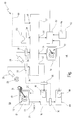
- a medical device in its entirety is designated by the reference numeral 10.
- the device 10 includes a display unit 12, which in the preferred embodiment is a touch screen.
- the display unit 12 could also be an analog CRT monitor, a simple LCD monitor, a beamer, or any other display unit.
- the touch screen 12 also simultaneously forms an input device, here represented by the hand 14 of an operator.
- the reference numeral 16 designates a medical computer PC (personal computer) equipped with a so-called frame grabber card 18.
- the task of the frame grabber card 18 is to record an analog video signal, in particular a so-called S-VHS signal, to digitize it and then to make it available to the internal processing unit (not shown here) of the PC.
- the PC 16 is connected to the touch-sensitive screen 12 via two connections 20, 22.
- the connection 20 is a conventional video signal connection, for example a VGA connection or a DVI connection, via which the display unit is connected to a PC.
- the PC 16 thus controls the display unit 12 via the connection 20.
- connection 22 in the preferred embodiment is a digital data connection through which input data 24 is transmitted from the touch screen 12 to the PC 16.
- the connection 22 is here in particular a serial RS-232 connection. However, it could also be, for example, a PS2 connection, a USB connection or a parallel data connection.
- the PC 16 evaluates the input data 24 as if it were input data from a mouse.
- the reference numeral 26 denotes a camera unit, which in particular includes an endoscopic camera and a corresponding control device (not shown separately). With the camera unit 26, for example, an internal organ 28 of a patient not otherwise shown here is recorded.
- the camera unit 26 is connected via a buffer amplifier 30 or a separating transformer with a so-called video crossbar. Deviating from the block diagram representation shown here, the isolating amplifier 30 can also be integrated, for example, in the camera unit 26 or the mentioned control unit.
- the video router 32 has a plurality of inputs 34, 36, 38, 40, to each of which a video signal source can be connected. Furthermore, has the Video crossbar 32 a series of outputs 42, 44, 46, at which video signals are output. In the embodiment shown, both the signals at the video inputs 34-40 and the video signals at the outputs 42-46 are S-VHS signals. However, other types of video signals can be used here as well.
- the camera unit 26 is connected via the isolating amplifier 30 to the input 34 of the video crossbar 32.
- a further camera unit 48 is connected via a further isolation amplifier.
- the camera unit 48 here is, for example, a 3D camera with a corresponding control unit, which makes it possible to record three-dimensional images.
- other types of video signal sources can also be connected here.
- the reference numeral 50 designates here by way of example for another video source a CD or DVD player which is connected to the input 38 of the video crossbar 32.
- the CD or DVD player 50 serves, for example, to provide archived image material for output on the display unit 12.
- An image processing unit 52 is connected to the input 40 of the video crossbar 32.
- the image processing unit 52 is preferably a commercially available image processing unit for superimposing handwritten processing marks on a video image. Preferably, this is a unit sold by Boeckeler Instruments Inc., 4650 South Butterfield Drive, Arlington, Ariz., USA under the name "Pointmaker®” PVI-44.
- the image processing unit 52 is also connected to the output 46 of the video crossbar 32 so that a loop is formed.
- a second display unit 54 is connected here.
- the output 42 is connected to the frame grabber card 18 via a further isolation amplifier 30.
- the configuration shown is exemplary and, in particular, the second camera unit 48, the CD / DVD player 50 and the second Display unit 54 are not required for the realization of the invention.
- the use of the video router 32 is here only a preferred embodiment.
- the task of the video router 32 is to selectively switch on the video signals applied to the various inputs 34-40 to one or more of the outputs 42-46.
- the isolation amplifiers 30 are preferably used in order to ensure electrical isolation between the sterile working area (designated here by reference numeral 56) and the non-sterile area 58.
- the separation between the sterile area 56 and the non-sterile area 58 is symbolically indicated here by a line 60.
- the reference numeral 62 here also denotes a digitizer tray on which one can make manual inputs with the aid of a pen 64, which are read in and processed by the image processing unit 52. Accordingly, the digitizer tray 62 is connected to the image processing unit 52 via a corresponding port. Also, the Digitizertablett 62 is not mandatory for the practical realization of the invention and therefore optional.
- the reference numeral 66 further denotes an interface unit, which is equipped in the present embodiment with an interface module 68 in the form of a plug-in card (board).
- the interface unit 66 is connected via the interface module 68 to a further input of the image processing unit 52.
- the interface unit 66 is connected to the PC 16 via a further isolation amplifier 30 (which may also be integrated in the interface unit 66).
- the connection between the PC 16 and the interface unit 66 is a digital bus connection, in particular a CAN-based bus connection as described by the assignee of the present invention under the designation SCB for the Networking of medical devices is offered.
- the connection between the interface module 68 and the image processing unit 52 is an RS-232 connection in the preferred embodiment. Alternatively, however, it could also be a USB connection, a parallel data connection or another, preferably standardized data connection.
- the interface module 68 performs protocol translation by translating input data 24 (in the preferred embodiment in SCB connection data format) received from the PC 16 into the digital data format of the RS-232 link to the image processing unit 52.
- the attending physician now has the option to mark 14 areas on the touch screen with his or her hand.
- the corresponding coordinates are transmitted as input data 24 to the PC 16 and detected there as mouse movements.
- the attending physician can, among other things, control medical devices (not shown here) connected to the PC 16, such as, for example, insufflators, an operating table or also the surgical lighting.
- control medical devices not shown here
- the PC 16 can set the PC 16 by a corresponding input command in a "marking or drawing mode" in which subsequent inputs on the touch-sensitive screen 12 are interpreted as processing notes.
- the PC 16 converts the then detected mouse movements into graphical symbols.
- a graphic symbol in the form of a hand-drawn marking arrow is designated by the reference numeral 70 in the figure.
- the icon 70 is not displayed directly on the display unit 12. Rather, the PC 16 sends the mouse coordinates detected by it to the interface unit 66, where they are converted by means of the interface module 68 in the data format of the image processing unit 52.
- the image processing unit 52 also receives, via the output 46 of the video router 32, the primary image and overlays the icon 70.
- the combined image then transmits the image processing unit 52 as a secondary image to the video router 32 (input 40). From there it passes via the frame grabber card 18 again to the display unit 12, on which now the secondary image 72 provided with the symbol 70 is displayed.
- the attending physician may then insert further tags or comments which are displayed again on the display unit 12 in the same manner, with the image initially displayed on the display unit 12 being the primary picture in the sense of the present invention.
- the secondary image 72 is also displayed on the remote display unit 54, which is available for example for training purposes or for data archiving.
- an interface module for use in a device according to claim 9 adapted to input data (24) from an input device (12) located in the sterile workspace (56) into a data format for an image processing unit located outside of the sterile workspace (56) (52) implement.
- the primary image is a medical image of a patient (28), in particular a photograph produced endoscopically in the sterile work area (56).
- a touch-sensitive screen (12) is provided as the input device, which preferably also forms the display unit.
- the input data (24) are transmitted to the image processing unit (52) via a galvanic separation point (30).
- the input data (24) are subjected to protocol conversion during transmission to the image processing unit (52).
- the input data (24) are transmitted in a digital format to the image processing unit (52).
- the primary image is transmitted as an analog image signal to the image processing unit (52).
- the secondary image (72) is displayed on a second display unit (54) which is arranged outside the sterile working area (56).
Abstract
Description
Die vorliegende Erfindung betrifft eine Vorrichtung zum Erzeugen eines mit Bearbeitungsvermerken versehenen Bildes in einem sterilen Arbeitsbereich einer medizinischen Einrichtung.The present invention relates to an apparatus for generating an annotated image in a sterile work area of a medical facility.
In der modernen Medizin werden Behandlungen mehr und mehr unter Verwendung von technischen bildgebenden Verfahren durchgeführt. Dabei werden beispielsweise miniaturisierte Kameras in den Körper eines Patienten eingeführt, und das mit der Kamera aufgenommene Bild wird dem behandelnden Arzt auf einem in seinem Arbeitsbereich installierten Monitor angezeigt. Der behandelnde Arzt kann auf diese Weise beispielsweise ein inneres Organ oder ein Gelenk zu Diagnosezwecken begutachten und auch chirurgische Eingriffe minimal-invasiv durchführen. Um die Behandlung eines Patienten so effizient und einfach wie möglich zu machen, ist es dabei von Vorteil, wenn der Monitor im Arbeitsbereich des Arztes, d.h. im sterilen Bereich, angeordnet ist. Der Arzt hat damit die Möglichkeit, sämtliche Eingriffe, die er am Patienten vornimmt, "live" auf dem Monitor zu verfolgen, wobei das entsprechende Monitorbild beispielsweise mit einer endoskopischen Kamera aufgenommen wird. Die Erfindung ist allerdings nicht auf Anwendungen beschränkt, bei denen Bilder mit Hilfe von endoskopischen Kameras erzeugt werden. Wenngleich es sich dabei um einen bevorzugten Anwendungsfall handelt, spielt die Herkunft der Bilder für die vorliegende Erfindung eine untergeordnete Rolle. Beispielsweise können die Bilder auch Röntgenbilder oder Aufnahmen aus einem Archiv sein, die beispielsweise zu Vergleichszwecken auf den Monitor im Arbeitsbereich des Arztes eingespielt werden.In modern medicine, treatments are being carried out more and more using technical imaging techniques. In this case, for example, miniaturized cameras are introduced into the body of a patient, and the image taken with the camera is displayed to the attending physician on a monitor installed in his workspace. The attending physician can on this For example, examine an internal organ or a joint for diagnostic purposes and perform surgery minimally invasive. In order to make the treatment of a patient as efficient and simple as possible, it is advantageous if the monitor is arranged in the working area of the doctor, ie in the sterile area. The doctor has the opportunity to follow all interventions that he makes on the patient "live" on the monitor, the corresponding monitor image is recorded, for example, with an endoscopic camera. However, the invention is not limited to applications in which images are generated by means of endoscopic cameras. Although this is a preferred application, the origin of the images plays a minor role in the present invention. For example, the images can also be X-ray images or recordings from an archive, which are recorded for example for comparison purposes on the monitor in the workspace of the doctor.
Darüber hinaus müssen der oder die behandelnden Ärzte bei einem chirurgischen Eingriff heutzutage eine Vielzahl von Geräten bedienen, die häufig ebenfalls im sterilen Bereich angeordnet sind. Um die zahlreichen Geräte möglichst effizient und komfortabel bedienen zu können, kommen moderne Netzwerk- und Kommunikationstechnologien zum Einsatz. Beispielsweise bietet die Anmelderin der vorliegenden Erfindung unter der Bezeichnung "OR-1" ein System für Operationssäle an, bei dem verschiedene Komponenten innerhalb und außerhalb des sterilen Arbeitsbereichs miteinander vernetzt sind. Aus
Um die Einsatzmöglichkeiten eines solchen Systems weiter zu verbessern, ist es wünschenswert, das angezeigte Bild mit Kommentaren, Anmerkungen, Markierungen und dergleichen, allgemein also mit Bearbeitungsvermerken, zu versehen. Hierdurch wird beispielsweise eine Diskussion zwischen mehreren behandelnden Ärzten bei der Erstellung eines Befundes erleichtert. Auch zu Ausbildungs- und Schulungszwecken ist es wünschenswert, wenn beispielsweise ein erfahrener Arzt Bereiche im angezeigten Bild markieren und mit Kommentaren versehen kann.In order to further improve the capabilities of such a system, it is desirable to provide the displayed image with comments, annotations, markers, and the like, generally with edit annotations. This facilitates, for example, a discussion between several treating physicians in the preparation of a report. Also for educational and training purposes For example, it may be desirable for an experienced physician to be able to mark and annotate areas in the displayed image.
Für Anwendungen außerhalb des medizinischen Bereichs, beispielsweise für Büroanwendungen und andere kommerzielle Zwecke, gibt es Geräte, die es erlauben, ein auf einer Anzeigeeinheit (Monitor, Beamer oder ähnliches) angezeigtes Bild mit Kommentaren und Markierungen zu versehen. Beispielsweise bietet die Firma Boeckeler Instruments, Inc. mit Sitz in Tucson, Arizona, USA entsprechende Geräte unter der Bezeichnung "Pointmaker®" an. Diese Geräte haben jedoch den Nachteil, dass sie nicht für Anwendungen im medizinischen Bereich konzipiert sind und daher nicht im sterilen Arbeitsbereich eingesetzt werden dürfen.For non-medical applications, such as office applications and other commercial purposes, there are devices that allow annotations and markings to be displayed on a display unit (monitor, projector, or the like). For example, Boeckeler Instruments, Inc., based in Tucson, Arizona, USA, offers such devices under the name "Pointmaker®". However, these devices have the disadvantage that they are not designed for applications in the medical field and therefore must not be used in the sterile work area.
Eine Möglichkeit, um dem oben beschriebenen Bedürfnis Rechnung zu tragen, wäre die Nutzung der kommerziell erhältlichen Geräte außerhalb des sterilen Arbeitsbereichs, wobei das betreffende Bild aus dem sterilen Arbeitsbereich dann zusätzlich noch einmal auf einen zweiten, außerhalb des sterilen Bereichs angeordneten Monitor übertragen werden müsste. Nachteilig ist hierbei, dass der behandelnde Arzt den sterilen Arbeitsbereich verlassen muss, um Bearbeitungsvermerke in das angezeigte Bild einzufügen.One way to meet the need described above would be to use the commercially available equipment outside of the sterile work area, where the relevant image from the sterile work area would have to be additionally transferred to a second monitor located outside the sterile area. The disadvantage here is that the attending physician must leave the sterile work area to insert processing notes in the displayed image.
Eine weitere Möglichkeit wäre, kommerziell erhältliche Geräte so umzurüsten, dass sie die Anforderungen für eine Verwendung im sterilen Arbeitsbereich eines Operationssaals erfüllen. Alternativ hierzu könnte man darangehen, ein für medizinische Anwendungen geeignetes Gerät zu entwickeln, das die gewünschte Funktionalität, wie sie von kommerziell erhältlichen Geräten bekannt ist, von sich aus beinhaltet. Beide Ansätze sind jedoch aufwendig und damit teuer.Another option would be to retrofit commercially available equipment to meet the requirements for use in the sterile operating room of an operating room. Alternatively, one could proceed to develop a medical grade device that inherently incorporates the desired functionality known from commercially available devices. Both approaches are complicated and therefore expensive.
Vor diesem Hintergrund ist es eine Aufgabe der vorliegenden Erfindung, auf einfache und kostengünstige Weise eine Möglichkeit bereitzustellen, die es einem behandelnden Arzt erlaubt, ein medizinisches Bild, insbesondere ein endoskopisches Videobild, vom sterilen Bereich aus mit Bearbeitungsvermerken zu versehen.Against this background, it is an object of the present invention to provide, in a simple and cost-effective manner, a possibility that allows a treating physician to provide a medical image, in particular an endoscopic video image, with processing marks from the sterile area.
Die Aufgabe wird gemäß einem Aspekt der Erfindung durch eine Vorrichtung der eingangs genannten Art gelöst, mit
- einer in dem sterilen Arbeitsbereich angeordneten medizinischen Anzeigeeinheit zum Darstellen eines primären Bildes,
- einem in dem sterilen Arbeitsbereich angeordneten Eingabegerät zum Erzeugen von Eingabedaten, wobei die Eingabedaten den Bearbeitungsvermerken entsprechen, und
- einer außerhalb des sterilen Bereichs angeordneten Bildverarbeitungseinheit, die dazu ausgebildet ist, die Eingabedaten und das primäre Bild aufzunehmen und zu einem sekundären Bild zusammenzuführen,
- wobei die medizinische Anzeigeeinheit und die Bildverarbeitungseinheit über eine Schnittstelle verbunden sind, so dass das sekundäre Bild an die Anzeigeeinheit übertragbar und dort darstellbar ist.
- a medical display unit arranged in the sterile work area for displaying a primary image,
- an input device arranged in the sterile work area for generating input data, the input data corresponding to the processing comments, and
- an image processing unit disposed outside the sterile area, which is designed to record the input data and the primary image and to merge them into a secondary image,
- wherein the medical display unit and the image processing unit are connected via an interface, so that the secondary image can be transmitted to the display unit and displayed there.
Die Anmeldung offenbart außerdem ein Verfahren zum Erzeugen eines mit Bearbeitungsvermerken versehenen Bildes in einem sterilen Arbeitsbereich einer medizinischen Einrichtung, wobei das Verfahren folgende Schritte aufweist:
- Darstellen eines primären Bildes auf einer medizinischen Anzeigeeinheit, die in dem sterilen Arbeitsbereich angeordnet ist,
- Bereitstellen eines Eingabegerätes zum Erzeugen von Eingabedaten in dem sterilen Arbeitsbereich, wobei die Eingabedaten den Bearbeitungsvermerken entsprechen,
- Einlesen der Eingabedaten und Übertragen der Eingabedaten an eine Bildverarbeitungseinheit, die außerhalb des sterilen Bereichs angeordnet ist,
- Übertragen des primären Bildes an die Bildverarbeitungseinheit,
- Erzeugen eines sekundären Bildes in der Bildverarbeitungseinheit durch Zusammenführen des primären Bildes und der Eingabedaten, und
- Übertragen des sekundären Bildes an die Anzeigeeinheit und Darstellen des sekundären Bildes auf der Anzeigeeinheit.
- Displaying a primary image on a medical display unit located in the sterile workspace;
- Providing an input device for generating input data in the sterile work area, the input data corresponding to the processing comments,
- Reading the input data and transmitting the input data to an image processing unit located outside the sterile area,
- Transferring the primary image to the image processing unit,
- Generating a secondary image in the image processing unit by merging the primary image and the input data, and
- Transmitting the secondary image to the display unit and displaying the secondary image on the display unit.
Das vorgeschlagene Verfahren und die entsprechende Vorrichtung beruhen damit auf der Idee, sowohl das primäre, mit den Bearbeitungsvermerken zu versehende Bild als auch die Eingabedaten, die die Bearbeitungsvermerke repräsentieren, aus dem sterilen Bereich "nach außen", d.h. in einen nicht-sterilen Bereich, zu übertragen. Dort können das primäre Bild und die Eingabedaten dann auf relativ einfache und kostengünstige Weise zusammengeführt werden, wobei vorteilhafterweise für diesen Teilschritt eine kommerziell erhältliche und damit für medizinische Anwendungen an sich nicht zugelassene Bildverarbeitungseinheit verwendet wird. Statt eine kommerziell erhältliche Bildverarbeitungseinheit für eine Anwendung in medizinischen Bereichen aufzurüsten, wird hiernach also die Aufbereitung des mit Bearbeitungsvermerken versehenen Bildes in einem unkritischen Bereich ausgelagert. Die "Auslagerung" erfolgt jedoch so, dass ein behandelnder Arzt die Eingabedaten trotzdem von seinem sterilen Arbeitsbereich aus erzeugen kann. Der vorgeschlagene Weg verbindet somit die Vorteile der oben genannten Alternativlösungen.The proposed method and apparatus are thus based on the idea that both the primary image to be annotated and the input data representing the processing indicia are "out of the box", i.e., out of the sterile area. into a non-sterile area. There, the primary image and the input data can then be combined in a relatively simple and cost-effective manner, advantageously for this sub-step a commercially available and thus not approved for medical applications per se image processing unit is used. Instead of upgrading a commercially available image processing unit for use in medical fields, the processing of the image provided with processing comments is therefore outsourced in a non-critical area. However, the "outsourcing" is done so that a treating physician can still generate the input data from his sterile work area. The proposed path thus combines the advantages of the alternative solutions mentioned above.
Nachteil der vorgeschlagenen Vorgehensweise ist, dass sowohl die Eingabedaten als auch das primäre Bild zu der entfernt angeordneten Bildverarbeitungseinheit übertragen werden müssen, was einen nicht unerheblichen Kommunikationsaufwand bedeutet. Es hat sich jedoch gezeigt, dass dieser Aufwand einfacher und kostengünstiger zu bewältigen ist, als man zunächst vermuten konnte. Die genannte Aufgabe ist daher vollständig gelöst.Disadvantage of the proposed approach is that both the input data and the primary image must be transmitted to the remote image processing unit, which means a considerable communication effort. However, it has been found that this effort is easier and less expensive to deal with than one might initially suspect. The stated task is therefore completely solved.
Darüber hinaus besitzen das neue Verfahren und die neue Vorrichtung den Vorteil, dass das mit den Bearbeitungsvermerken versehene, sekundäre Bild, für eine weitere Verarbeitung außerhalb des sterilen Bereichs unmittelbar zur Verfügung steht. Diese weitere Verarbeitung kann beispielsweise die Anzeige auf einem abgesetzten Schulungsmonitor und/oder die Archivierung in einer elektronischen Patientenkartei sein. Das neue System bietet daher einen erweiterten Anwendungsbereich.Moreover, the new method and apparatus have the advantage that the secondary image provided with the processing marks is immediately available for further processing outside of the sterile area. This further processing can be, for example, the display on a remote training monitor and / or the archiving in an electronic patient file. The new system therefore offers a wider range of applications.
In einer Ausgestaltung der Erfindung ist das primäre Bild eine medizinische Aufnahme eines Patienten, insbesondere eine in dem sterilen Arbeitsbereich endoskopisch erzeugte Aufnahme.In one embodiment of the invention, the primary image is a medical image of a patient, in particular a recording produced endoscopically in the sterile work area.
In dieser bevorzugten Ausgestaltung kommen die Vorteile der Erfindung besonders deutlich zur Geltung. So ist die Analyse einer medizinischen Aufnahme eines Patienten und insbesondere die Analyse einer aktuellen Aufnahme des Patienten während einer Behandlung ein Anwendungsfall, der durch die Bereitstellung von Bearbeitungsvermerken einfacher und übersichtlicher wird. Beispielsweise können Missverständnisse bei einer schwierigen Operation, an der mehrere behandelnde Ärzte beteiligt sind, in dieser bevorzugten Ausgestaltung einfacher vermieden werden.In this preferred embodiment, the advantages of the invention are particularly clear advantage. Thus, the analysis of a medical admission of a patient and in particular the analysis of a current admission of the patient during a treatment is an application which becomes simpler and clearer by the provision of processing comments. For example, misunderstandings in a difficult operation in which several treating physicians are involved can be more easily avoided in this preferred embodiment.
In einer weiteren Ausgestaltung ist das Eingabegerät ein berührungsempfindlicher Bildschirm, der vorzugsweise auch die Anzeigeeinheit bildet.In a further embodiment, the input device is a touch-sensitive screen, which preferably also forms the display unit.
Berührungsempfindliche Bildschirme (so genannte "touch-screens") sind an sich bekannt und werden auch bereits als Anzeige- und Bedieneinheiten in medizinischen Einrichtungen eingesetzt. In der bevorzugten Ausgestaltung besitzt ein berührungsempfindlicher Bildschirm den besonderen Vorteil, dass der behandelnde Arzt Bearbeitungsvermerke sehr einfach und schnell allein mit Hilfe seiner Hände erzeugen kann. Darüber hinaus ist ein berührungsempfindlicher Bildschirm hervorragend als Eingabegerät für den sterilen Arbeitsbereich geeignet, und er benötigt insbesondere in der bevorzugten Ausgestaltung keinen zusätzlichen Platz. Die Eingabedaten sind in der bevorzugten Ausgestaltung insbesondere die Koordinaten auf dem berührungsempfindlichen Bildschirm, an denen eine Berührung durch den behandelnden Arzt detektiert wird.Touch screens (so-called "touch screens") are known per se and are already used as display and control units in medical facilities. In the preferred embodiment, a touch-sensitive screen has the particular advantage that the attending physician can very easily and quickly generate processing marks with the help of his hands. In addition, a touch screen is well suited as an input device for the sterile work area, and it requires no extra space, especially in the preferred embodiment. The input data in the preferred embodiment is in particular the coordinates on the touch-sensitive Screen on which contact by the attending physician is detected.
In einer weiteren Ausgestaltung werden die Eingabedaten über eine galvanische Trennstelle an die Bildverarbeitungseinheit übertragen.In a further refinement, the input data is transmitted to the image processing unit via a galvanic separation point.
Diese Ausgestaltung besitzt den Vorteil, dass der sterile Arbeitsbereich und die darin verwendeten Geräte sehr zuverlässig von dem nicht-sterilen Außenbereich abgeschottet sind. Die Funktionssicherheit und Funktionszuverlässigkeit der Gesamteinrichtung wird hierdurch erhöht.This embodiment has the advantage that the sterile work area and the devices used therein are very reliably sealed off from the non-sterile exterior area. The functional reliability and functional reliability of the overall device is thereby increased.
In einer weiteren Ausgestaltung werden die Eingabedaten bei der Übertragung an die Bildverarbeitungseinheit einer Protokollumsetzung unterzogen. Dementsprechend ist in einer bevorzugten Ausgestaltung der neuen Vorrichtung ein Protokollumsetzer vorhanden, der weiter bevorzugt in Form eines Schnittstellenmoduls, insbesondere einer Schnittstellenkarte, ausgebildet ist.In a further refinement, the input data is subjected to protocol conversion during transmission to the image processing unit. Accordingly, in a preferred embodiment of the new device, a protocol converter is provided, which is further preferably designed in the form of an interface module, in particular an interface card.
Diese Ausgestaltung besitzt den Vorteil, dass allein durch Adaptierung des Protokollumsetzers eine beliebige und gegebenenfalls austauschbare Bildverarbeitungseinheit verwendet werden kann. Insbesondere wird hierdurch die Verwendung von kommerziell erhältlichen Bildverarbeitungseinheiten erleichtert, was eine besonders kostengünstige Realisierung ermöglicht.This embodiment has the advantage that any and possibly interchangeable image processing unit can be used solely by adapting the protocol converter. In particular, this facilitates the use of commercially available image processing units, which enables a particularly cost-effective implementation.
In einer weiteren Ausgestaltung werden die Eingabedaten in einem digitalen Format an die Bildverarbeitungseinheit übertragen. Des weiteren ist es bevorzugt, wenn das primäre Bild als analoges Bildsignal an die Bildverarbeitungseinheit übertragen wird.In a further embodiment, the input data is transmitted in a digital format to the image processing unit. Furthermore, it is preferred if the primary image is transmitted as an analog image signal to the image processing unit.
Grundsätzlich könnten die Eingabedaten auch in analoger Form bzw. das primäre Bild in digitaler Form an die Bildverarbeitungseinheit übertragen werden. Die bevorzugten Ausgestaltungen erleichtern demgegenüber jedoch die praktische Realisierung. So kann insbesondere eine Protokollumsetzung bei digitalen Eingabedaten relativ einfach und kostengünstig per Software realisiert werden. Die Übertragung des primären Bildes als analoges Bildsignal ist demgegenüber mit heutigen Mitteln einfacher und schneller als in digitaler Form zu realisieren. Außerdem kann in diesem Fall auf kostengünstige und erprobte Komponenten zurückgegriffen werden.In principle, the input data could also be transmitted in analog form or the primary image in digital form to the image processing unit. The preferred embodiments, however, on the other hand facilitate the practical realization. Thus, in particular, a protocol conversion for digital input data relatively easy and inexpensive to be realized by software. In contrast, the transmission of the primary image as an analog image signal is simpler and faster to realize with current means than in digital form. In addition, cost-effective and proven components can be used in this case.
In einer weiteren Ausgestaltung wird das sekundäre Bild auf einer zweiten Anzeigeeinheit dargestellt, die außerhalb des sterilen Arbeitsbereichs angeordnet ist.In a further embodiment, the secondary image is displayed on a second display unit, which is arranged outside the sterile working area.
Diese Ausgestaltung nutzt die Möglichkeiten des neuen Verfahrens in besonders vorteilhafter Weise, da hierdurch beispielsweise Ausbildung und Schulungen, Datenarchivierung und auch Videokonferenzen, an denen weit entfernt sitzende Fachleute beteiligt sind, wesentlich vereinfacht werden.This embodiment takes advantage of the possibilities of the new method in a particularly advantageous manner, as this, for example, training and training, data archiving and video conferencing, in which far-seated professionals are involved, are significantly simplified.
Es versteht sich, dass die vorstehend genannten und die nachstehend noch zu erläuternden Merkmale nicht nur in der jeweils angegebenen Kombination, sondern auch in anderen Kombinationen oder in Alleinstellung verwendbar sind, ohne den Rahmen der vorliegenden Erfindung zu verlassen.It is understood that the features mentioned above and those yet to be explained below can be used not only in the particular combination given, but also in other combinations or in isolation, without departing from the scope of the present invention.
In der einzigen Figur ist ein bevorzugtes Ausführungsbeispiel der Erfindung in einem vereinfachten Blockschaltbild dargestellt.In the single figure, a preferred embodiment of the invention is shown in a simplified block diagram.
In der Figur ist eine medizinische Einrichtung in ihrer Gesamtheit mit der Bezugsziffer 10 bezeichnet.In the figure, a medical device in its entirety is designated by the
Die Einrichtung 10 beinhaltet eine Anzeigeeinheit 12, die in dem bevorzugten Ausführungsbeispiel ein berührungsempfindlicher Bildschirm ist. Alternativ hierzu könnte die Anzeigeeinheit 12 jedoch auch ein analoger Röhrenmonitor, ein einfacher LCD-Monitor, ein Beamer oder eine beliebige andere Anzeigeeinheit sein. In dem bevorzugten Ausführungsbeispiel bildet der berührungsempfindliche Bildschirm 12 gleichzeitig auch ein Eingabegerät, was hier durch die Hand 14 eines Bedieners dargestellt ist.The
Mit der Bezugsziffer 16 ist ein für medizinische Zwecke ausgebildeter PC (personal computer) bezeichnet, der mit einer so genannten Framegrabberkarte 18 ausgerüstet ist. Aufgabe der Framegrabberkarte 18 ist es, ein analoges Videosignal, insbesondere ein so genanntes S-VHS-Signal aufzunehmen, zu digitalisieren und anschließend der internen Verarbeitungseinheit (hier nicht dargestellt) des PCs zur Verfügung zu stellen.The
Der PC 16 ist über zwei Verbindungen 20, 22 mit dem berührungsempfindlichen Bildschirm 12 verbunden. Die Verbindung 20 ist eine übliche Videosignalverbindung, beispielsweise eine VGA-Verbindung oder eine DVI-Verbindung, über die die Anzeigeeinheit an einen PC angeschlossen wird. Der PC 16 steuert die Anzeigeeinheit 12 folglich über die Verbindung 20 an.The
Die Verbindung 22 ist in dem bevorzugten Ausführungsbeispiel eine digitale Datenverbindung, über die Eingabedaten 24 von dem berührungsempfindlichen Bildschirm 12 an den PC 16 übertragen werden. Die Verbindung 22 ist hier insbesondere eine serielle RS-232-Verbindung. Es könnte jedoch beispielsweise auch eine PS2-verbindung, eine USB-Verbindung oder eine parallele Datenverbindung sein. Der PC 16 wertet die Eingabedaten 24 aus, als wären es Eingabedaten von einer Maus.The
Mit der Bezugsziffer 26 ist eine Kameraeinheit bezeichnet, die hier insbesondere eine endoskopische Kamera und ein entsprechendes Steuergerät (nicht gesondert dargestellt) beinhaltet. Mit der Kameraeinheit 26 wird beispielsweise ein inneres Organ 28 eines hier im Übrigen nicht dargestellten Patienten aufgenommen. Die Kameraeinheit 26 ist über einen Trennverstärker 30 oder einen Trenntrafo mit einer sogenannten Videokreuzschiene (video crossbar) verbunden. Der Trennverstärker 30 kann abweichend von der hier gezeigten Blockschaltbilddarstellung beispielsweise auch in der Kameraeinheit 26 bzw. der erwähnten Steuereinheit integriert sein.The
Die Videokreuzschiene 32 besitzt eine Vielzahl von Eingängen 34, 36, 38, 40, an die jeweils eine Videosignalquelle angeschlossen werden kann. Des Weiteren besitzt die Videokreuzschiene 32 eine Reihe von Ausgängen 42, 44, 46, an denen Videosignale ausgegeben werden. In dem gezeigten Ausführungsbeispiel sind sowohl die Signale an den Videoeingängen 34-40 als auch die Videosignale an den Ausgängen 42-46 S-VHS-Signale. Es können hier jedoch auch andere Arten von Videosignalen verwendet werden.The
Die Kameraeinheit 26 ist über den Trennverstärker 30 an den Eingang 34 der Videokreuzschiene 32 angeschlossen. An den Eingang 36 ist über einen weiteren Trennverstärker eine weitere Kameraeinheit 48 angeschlossen. Die Kameraeinheit 48 ist hier beispielsweise im Unterschied zur Kameraeinheit 26 eine 3D-Kamera mit entsprechender Steuereinheit, die es ermöglicht, dreidimensionale Bilder aufzunehmen. Des Weiteren können hier auch andere Arten von Videosignalquellen angeschlossen sein.The
Mit der Bezugsziffer 50 ist hier beispielhaft für eine andere Videoquelle ein CD- oder DVD-Player bezeichnet, der an den Eingang 38 der Videokreuzschiene 32 angeschlossen ist. Der CD- oder DVD-Player 50 dient beispielsweise dazu, archiviertes Bildmaterial zur Ausgabe auf der Anzeigeeinheit 12 bereitzustellen.The
An den Eingang 40 der Videokreuzschiene 32 ist eine Bildverarbeitungseinheit 52 angeschlossen. Die Bildverarbeitungseinheit 52 ist bevorzugt eine kommerziell erhältliche Bildverarbeitungseinheit zum Überlagern von handschriftlichen Bearbeitungsvermerken auf einem Videobild. Bevorzugt handelt es sich hier um eine Einheit, die von der Firma Boeckeler Instruments Inc., 4650 South Butterfield Drive, Tucson, Arizona, USA unter der Bezeichnung "Pointmaker®" PVI-44 angeboten wird.An
Die Bildverarbeitungseinheit 52 ist ferner auch an den Ausgang 46 der Videokreuzschiene 32 angeschlossen, so dass eine Schleife gebildet wird. An den Ausgang 44 der Videokreuzschiene 32 ist hier eine zweite Anzeigeeinheit 54 angeschlossen. Der Ausgang 42 ist über einen weiteren Trennverstärker 30 mit der Framegrabberkarte 18 verbunden. Es versteht sich, dass die gezeigte Konfiguration beispielhaft ist und insbesondere die zweite Kameraeinheit 48, der CD-/DVD-Player 50 und die zweite Anzeigeeinheit 54 für die Realisierung der Erfindung nicht erforderlich sind. Darüber hinaus ist auch die Verwendung der Videokreuzschiene 32 hier nur ein bevorzugtes Ausführungsbeispiel. Aufgabe der Videokreuzschiene 32 ist es nämlich, die an den verschiedenen Eingängen 34-40 anliegenden Videosignale wahlweise an einen oder mehrere der Ausgänge 42-46 durchzuschalten. Wird nur eine Videoquelle, beispielsweise also nur die Kameraeinheit 26, verwendet, genügt es, deren Videosignal über einen Splitter (hier nicht dargestellt) der Framegrabberkarte 18 und der Bildverarbeitungseinheit 52 zuzuführen. Bevorzugt werden jedoch auch in diesem Fall die Trennverstärker 30 verwendet, um eine galvanische Trennung zwischen dem sterilen Arbeitsbereich (hier mit Bezugsziffer 56 bezeichnet) und dem nicht-sterilen Bereich 58 zu gewährleisten.The
Die Trennung zwischen dem sterilen Bereich 56 und dem nicht-sterilen Bereich 58 ist hier durch eine Linie 60 symbolisch angedeutet.The separation between the
Mit der Bezugsziffer 62 ist hier des weiteren ein Digitizertablett bezeichnet, auf dem man mit Hilfe eines Stiftes 64 manuelle Eingaben machen kann, die von der Bildverarbeitungseinheit 52 eingelesen und verarbeitet werden. Dementsprechend ist das Digitizertablett 62 hier über einen entsprechenden Anschluss mit der Bildverarbeitungseinheit 52 verbunden. Auch das Digitizertablett 62 ist für die praktische Realisierung der Erfindung nicht zwingend erforderlich und daher optional.The
Mit der Bezugsziffer 66 ist des Weiteren eine Schnittstelleneinheit bezeichnet, die im hiesigen Ausführungsbeispiel mit einem Schnittstellenmodul 68 in Form einer Einsteckkarte (Platine) ausgerüstet ist. Ausgangsseitig ist die Schnittstelleneinheit 66 über das Schnittstellenmodul 68 mit einem weiteren Eingang der Bildverarbeitungseinheit 52 verbunden. Eingangsseitig ist die Schnittstelleneinheit 66 über einen weiteren Trennverstärker 30 (der auch in der Schnittstelleneinheit 66 integriert sein kann) mit dem PC 16 verbunden. In einem bevorzugten Ausführungsbeispiel ist die Verbindung zwischen dem PC 16 und der Schnittstelleneinheit 66 eine digitale Busverbindung, insbesondere eine CAN-basierte Busverbindung, wie sie von der Anmelderin der vorliegenden Erfindung unter der Bezeichnung SCB speziell für die Vernetzung von medizinischen Geräten angeboten wird. Die Verbindung zwischen dem Schnittstellenmodul 68 und der Bildverarbeitungseinheit 52 ist in dem bevorzugten Ausführungsbeispiel eine RS-232-Verbindung. Alternativ könnte es sich hier jedoch auch um eine USB-Verbindung, eine parallele Datenverbindung oder eine andere, bevorzugt standardisierte Datenverbindung handeln. Das Schnittstellenmodul 68 führt eine Protokollumsetzung durch, indem es von dem PC 16 empfangene Eingabedaten 24 (in dem bevorzugten Ausführungsbeispiel im Datenformat der SCB-Verbindung) in das digitale Datenformat der RS-232-Verbindung zur Bildverarbeitungseinheit 52 umsetzt.The
Die Funktionsweise der Einrichtung 10 ist nun wie folgt:
- Mit der Kameraeinheit 26 wird
das Organ 28 des Patienten aufgenommen. DasVideosignal der Kameraeinheit 26 wird über dieVideokreuzschiene 32der Framegrabberkarte 18 zugeführt, von dieser digitalisiert und anschließend überden PC 16 aufdem berührungsempfindlichen Bildschirm 12 ausgegeben. Dieses ausgegebene Bild ist das primäre Bild im Sinne der vorliegenden Erfindung.
- With the
camera unit 26, theorgan 28 of the patient is recorded. The video signal of thecamera unit 26 is supplied via thevideo crossbar 32 of theframe grabber card 18, digitized by this and then output via thePC 16 on the touch-sensitive screen 12. This output image is the primary image in the sense of the present invention.
Der behandelnde Arzt hat nun die Möglichkeit, mit seiner Hand 14 Bereiche auf dem berührungsempfindlichen Bildschirm zu markieren. Die entsprechenden Koordinaten werden als Eingabedaten 24 an den PC 16 übertragen und dort als Mausbewegungen detektiert. Durch die Eingabedaten kann der behandelnde Arzt u.a. an den PC 16 angeschlossene medizinische Geräte (hier nicht dargestellt), wie beispielsweise Insufflatoren, einen Operationstisch oder auch die OP-Beleuchtung, steuern. Des Weiteren kann er den PC 16 durch einen entsprechenden Eingabebefehl in einen "Markierungs- oder Zeichenmodus" versetzen, in dem nachfolgende Eingaben auf dem berührungsempfindlichen Bildschirm 12 als Bearbeitungsvermerke interpretiert werden. Der PC 16 setzt die dann detektierten Mausbewegungen in graphische Symbole um. Beispielhaft ist in der Figur ein graphisches Symbol in Form eines von Hand gezeichneten Markierungspfeils mit der Bezugsziffer 70 bezeichnet. Das Symbol 70 wird jedoch nicht unmittelbar auf der Anzeigeeinheit 12 angezeigt. Vielmehr sendet der PC 16 die von ihm detektierten Mauskoordinaten an die Schnittstelleneinheit 66, wo sie mit Hilfe des Schnittstellenmoduls 68 in das Datenformat der Bildverarbeitungseinheit 52 umgesetzt werden. Die Bildverarbeitungseinheit 52 erhält ferner über den Ausgang 46 der Videokreuzschiene 32 das primäre Bild und überlagert diesem das Symbol 70. Das kombinierte Bild überträgt die Bildverarbeitungseinheit 52 anschließend als sekundäres Bild an die Videokreuzschiene 32 (Eingang 40). Von dort gelangt es über die Framegrabberkarte 18 wiederum zu der Anzeigeeinheit 12, auf der nun das mit dem Symbol 70 versehene sekundäre Bild 72 angezeigt wird. Der behandelnde Arzt kann dann weitere Markierungen oder Kommentare einfügen, die auf dieselbe Weise wieder auf der Anzeigeeinheit 12 angezeigt werden, wobei jeweils das anfänglich auf der Anzeigeeinheit 12 angezeigte Bild das primäre Bild im Sinne der vorliegenden Erfindung ist.The attending physician now has the option to mark 14 areas on the touch screen with his or her hand. The corresponding coordinates are transmitted as
In dem hier gezeigten Ausführungsbeispiel wird das sekundäre Bild 72 außerdem auch auf der räumlich abgesetzten Anzeigeeinheit 54 angezeigt, die beispielsweise für Schulungszwecke oder auch für eine Datenarchivierung zur Verfügung steht.In addition, in the embodiment shown here, the
Insgesamt ist zunächst eine Vorrichtung zum Erzeugen eines mit Bearbeitungsvermerken versehenen Bildes in einem sterilen Arbeitsbereich (56) einer medizinischen Einrichtung (10) offenbart, die Vorrichtung mit
- einer in dem sterilen Arbeitsbereich (56) angeordneten medizinischen Anzeigeeinheit (12) zum Darstellen eines primären Bildes,
- einem in dem sterilen Arbeitsbereich (56) angeordneten Eingabegerät (12) zum Erzeugen von Eingabedaten (24), wobei die Eingabedaten (24) den Bearbeitungsvermerken entsprechen, und
- einer außerhalb des sterilen Bereichs (56) angeordneten Bildverarbeitungseinheit (52), die dazu ausgebildet ist, die Eingabedaten (24) und das primäre Bild aufzunehmen und zu einem sekundären Bild (72) zusammenzuführen,
- wobei die medizinische Anzeigeeinheit (12) und die Bildverarbeitungseinheit (52) über eine Schnittstelle (18, 32) verbunden sind, so dass das sekundäre Bild (72) an die Anzeigeeinheit (12) übertragbar und dort darstellbar ist.
- a medical display unit (12) arranged in the sterile work area (56) for displaying a primary image,
- an input device (12) arranged in the sterile work area (56) for generating input data (24), the input data (24) corresponding to the processing comments, and
- an image processing unit (52) disposed outside the sterile area (56) and adapted to receive the input data (24) and the primary image and merge them into a secondary image (72),
- wherein the medical display unit (12) and the image processing unit (52) are connected via an interface (18, 32), so that the secondary image (72) is transferable to the display unit (12) and displayable there.
Ferner ist ein Schnittstellenmodul zur Verwendung in einer Vorrichtung nach Anspruch 9, das dazu ausgebildet ist, Eingabedaten (24) von einem in dem sterilen Arbeitsbereich (56) angeordneten Eingabegerät (12) in ein Datenformat für eine außerhalb des sterilen Arbeitsbereichs (56) angeordnete Bildverarbeitungseinheit (52) umzusetzen.Further, an interface module for use in a device according to claim 9 adapted to input data (24) from an input device (12) located in the sterile workspace (56) into a data format for an image processing unit located outside of the sterile workspace (56) (52) implement.
Schließlich ist ein Verfahren zum Erzeugen eines mit Bearbeitungsvermerken versehenen Bildes in einem sterilen Arbeitsbereich (56) einer medizinischen Einrichtung (10) offenbart, mit den Schritten:
- Darstellen eines primären Bildes auf einer medizinischen Anzeigeeinheit (12), die in dem sterilen Arbeitsbereich (56) angeordnet ist,
- Bereitstellen eines Eingabegerätes (12) zum Erzeugen von Eingabedaten (24) in dem sterilen Arbeitsbereich (56), wobei die Eingabedaten (24) den Bearbeitungsvermerken entsprechen,
- Einlesen der Eingabedaten (24) und Übertragen der Eingabedaten (24) an eine Bildverarbeitungseinheit (52) die außerhalb des sterilen Bereichs (56) angeordnet ist,
- Übertragen des primären Bildes an die Bildverarbeitungseinheit (52),
- Erzeugen eines sekundären Bildes (72) in der Bildverarbeitungseinheit (52) durch Zusammenführen des primären Bildes und der Eingabedaten (24), und
- Übertragen des sekundären Bildes (72) an die Anzeigeeinheit und Darstellen des sekundären Bildes (72) auf der Anzeigeeinheit (12).
- Displaying a primary image on a medical display unit (12) located in the sterile work area (56)
- Providing an input device (12) for generating input data (24) in the sterile work area (56), the input data (24) corresponding to the processing comments,
- Reading the input data (24) and transmitting the input data (24) to an image processing unit (52) located outside the sterile area (56),
- Transferring the primary image to the image processing unit (52),
- Generating a secondary image (72) in the image processing unit (52) by merging the primary image and the input data (24), and
- Transmitting the secondary image (72) to the display unit and displaying the secondary image (72) on the display unit (12).
Dabei ist es vorteilhaft, wenn das primäre Bild eine medizinische Aufnahme eines Patienten (28) ist, insbesondere eine in dem sterilen Arbeitsbereich (56) endoskopisch erzeugte Aufnahme.In this case, it is advantageous if the primary image is a medical image of a patient (28), in particular a photograph produced endoscopically in the sterile work area (56).
Ferner ist es vorteilhaft, wenn als Eingabegerät ein berührungsempfindlicher Bildschirm (12) bereitgestellt wird, der vorzugsweise auch die Anzeigeeinheit bildet.Furthermore, it is advantageous if a touch-sensitive screen (12) is provided as the input device, which preferably also forms the display unit.
Ferner ist es vorteilhaft, wenn die Eingabedaten (24) über eine galvanische Trennstelle (30) an die Bildverarbeitungseinheit (52) übertragen werden.Furthermore, it is advantageous if the input data (24) are transmitted to the image processing unit (52) via a galvanic separation point (30).
Ferner ist es vorteilhaft, wenn die Eingabedaten (24) bei der Übertragung an die Bildverarbeitungseinheit (52) einer Protokollumsetzung unterzogen werden.Furthermore, it is advantageous if the input data (24) are subjected to protocol conversion during transmission to the image processing unit (52).
Ferner ist es vorteilhaft, wenn die Eingabedaten (24) in einem digitalen Format an die Bildverarbeitungseinheit (52) übertragen werden.Furthermore, it is advantageous if the input data (24) are transmitted in a digital format to the image processing unit (52).
Ferner ist es vorteilhaft, wenn das primäre Bild als analoges Bildsignal an die Bildverarbeitungseinheit (52) übertragen wird.Furthermore, it is advantageous if the primary image is transmitted as an analog image signal to the image processing unit (52).
Ferner ist es vorteilhaft, wenn das sekundäre Bild (72) auf einer zweiten Anzeigeeinheit (54) dargestellt wird, die außerhalb des sterilen Arbeitsbereichs (56) angeordnet ist.Furthermore, it is advantageous if the secondary image (72) is displayed on a second display unit (54) which is arranged outside the sterile working area (56).
Claims (15)
Applications Claiming Priority (2)
| Application Number | Priority Date | Filing Date | Title |
|---|---|---|---|
| DE10349649A DE10349649B3 (en) | 2003-10-17 | 2003-10-17 | A method and apparatus for generating an annotated image in a sterile work area of a medical facility |
| EP04790168A EP1675504B1 (en) | 2003-10-17 | 2004-10-07 | Generation of an image provided with processing information in a sterile working area |
Related Parent Applications (1)
| Application Number | Title | Priority Date | Filing Date |
|---|---|---|---|
| EP04790168.1 Division | 2004-10-07 |
Publications (3)
| Publication Number | Publication Date |
|---|---|
| EP2272425A2 true EP2272425A2 (en) | 2011-01-12 |
| EP2272425A8 EP2272425A8 (en) | 2011-02-23 |
| EP2272425A3 EP2272425A3 (en) | 2012-05-02 |
Family
ID=34442235
Family Applications (2)
| Application Number | Title | Priority Date | Filing Date |
|---|---|---|---|
| EP04790168A Active EP1675504B1 (en) | 2003-10-17 | 2004-10-07 | Generation of an image provided with processing information in a sterile working area |
| EP10185806A Ceased EP2272425A3 (en) | 2003-10-17 | 2004-10-07 | Generation of an image provided with annotations in a sterile working area |
Family Applications Before (1)
| Application Number | Title | Priority Date | Filing Date |
|---|---|---|---|
| EP04790168A Active EP1675504B1 (en) | 2003-10-17 | 2004-10-07 | Generation of an image provided with processing information in a sterile working area |
Country Status (4)
| Country | Link |
|---|---|
| US (1) | US8848987B2 (en) |
| EP (2) | EP1675504B1 (en) |
| DE (1) | DE10349649B3 (en) |
| WO (1) | WO2005037093A1 (en) |
Families Citing this family (18)
| Publication number | Priority date | Publication date | Assignee | Title |
|---|---|---|---|---|
| JP4336750B2 (en) | 2001-11-21 | 2009-09-30 | ブラッコ ディアグノスティックス,インク. | Apparatus, system and kit for collecting effluent from individuals |
| US8971597B2 (en) | 2005-05-16 | 2015-03-03 | Intuitive Surgical Operations, Inc. | Efficient vision and kinematic data fusion for robotic surgical instruments and other applications |
| US9492240B2 (en) | 2009-06-16 | 2016-11-15 | Intuitive Surgical Operations, Inc. | Virtual measurement tool for minimally invasive surgery |
| US7697827B2 (en) | 2005-10-17 | 2010-04-13 | Konicek Jeffrey C | User-friendlier interfaces for a camera |
| US7806850B2 (en) | 2005-10-24 | 2010-10-05 | Bracco Diagnostics Inc. | Insufflating system, method, and computer program product for controlling the supply of a distending media to an endoscopic device |
| US7907166B2 (en) | 2005-12-30 | 2011-03-15 | Intuitive Surgical Operations, Inc. | Stereo telestration for robotic surgery |
| JPWO2008084696A1 (en) * | 2006-12-27 | 2010-04-30 | 京セラ株式会社 | Broadcast receiver |
| US9532848B2 (en) | 2007-06-15 | 2017-01-03 | Othosoft, Inc. | Computer-assisted surgery system and method |
| PL2848192T3 (en) | 2007-10-15 | 2022-05-02 | University Of Maryland, Baltimore | Apparatus for use in studying a patient's colon |
| US8830224B2 (en) | 2008-12-31 | 2014-09-09 | Intuitive Surgical Operations, Inc. | Efficient 3-D telestration for local robotic proctoring |
| US9155592B2 (en) | 2009-06-16 | 2015-10-13 | Intuitive Surgical Operations, Inc. | Virtual measurement tool for minimally invasive surgery |
| ES2633144T3 (en) | 2010-11-24 | 2017-09-19 | Bracco Diagnostics Inc. | System to provide and control the supply of a dilatation medium for CT colonography |
| US11412998B2 (en) | 2011-02-10 | 2022-08-16 | Karl Storz Imaging, Inc. | Multi-source medical display |
| US10631712B2 (en) | 2011-02-10 | 2020-04-28 | Karl Storz Imaging, Inc. | Surgeon's aid for medical display |
| US10674968B2 (en) | 2011-02-10 | 2020-06-09 | Karl Storz Imaging, Inc. | Adjustable overlay patterns for medical display |
| US20140138270A1 (en) | 2012-11-16 | 2014-05-22 | Krishnan K. Ghosh | Surgical system |
| US10868950B2 (en) * | 2018-12-12 | 2020-12-15 | Karl Storz Imaging, Inc. | Systems and methods for operating video medical scopes using a virtual camera control unit |
| US11625825B2 (en) | 2019-01-30 | 2023-04-11 | Covidien Lp | Method for displaying tumor location within endoscopic images |
Citations (1)
| Publication number | Priority date | Publication date | Assignee | Title |
|---|---|---|---|---|
| US5788688A (en) | 1992-11-05 | 1998-08-04 | Bauer Laboratories, Inc. | Surgeon's command and control |
Family Cites Families (20)
| Publication number | Priority date | Publication date | Assignee | Title |
|---|---|---|---|---|
| US3772514A (en) * | 1971-11-08 | 1973-11-13 | Capintec Inc | Isolation amplifier |
| US4989253A (en) * | 1988-04-15 | 1991-01-29 | The Montefiore Hospital Association Of Western Pennsylvania | Voice activated microscope |
| US4877016A (en) | 1988-07-29 | 1989-10-31 | Kantor Edward A | Video endoscopic microscope |
| US5257998A (en) * | 1989-09-20 | 1993-11-02 | Mitaka Kohki Co., Ltd. | Medical three-dimensional locating apparatus |
| US5699798A (en) * | 1990-08-10 | 1997-12-23 | University Of Washington | Method for optically imaging solid tumor tissue |
| DE19534312A1 (en) * | 1995-09-15 | 1997-03-20 | Norbert Schmidt | Supplying picture information from surgical operating rooms |
| US6078681A (en) * | 1996-03-18 | 2000-06-20 | Marine Biological Laboratory | Analytical imaging system and process |
| US5970980A (en) * | 1996-07-12 | 1999-10-26 | Adair; Edwin L. | Sterile encapsulated operating room video monitor and video monitor support device |
| DE19648935B4 (en) * | 1996-11-26 | 2008-05-15 | IMEDOS Intelligente Optische Systeme der Medizin- und Messtechnik GmbH | Device and method for the examination of vessels |
| DE19858421A1 (en) * | 1998-12-17 | 2000-06-29 | Siemens Ag | Network connection for medical image system |
| CA2272040A1 (en) * | 1999-05-13 | 2000-11-13 | Ecole Polytechnique | Robotic observation camera for use in an operating room |
| US6791601B1 (en) * | 1999-11-11 | 2004-09-14 | Stryker Corporation | Multi-function image and video capture device for use in an endoscopic camera system |
| US6591239B1 (en) * | 1999-12-09 | 2003-07-08 | Steris Inc. | Voice controlled surgical suite |
| US6639789B2 (en) * | 2000-07-12 | 2003-10-28 | Karl Storz Gmbh & Co. Kg | Instrument and service unit for a surgical operating area |
| JP2002263063A (en) * | 2001-03-12 | 2002-09-17 | Asahi Optical Co Ltd | Endoscope system |
| CN100377685C (en) * | 2002-08-30 | 2008-04-02 | 奥林巴斯株式会社 | Medical treatment system, endoscope system, endoscope insert operation program, and endoscope device |
| JP4776937B2 (en) * | 2005-02-10 | 2011-09-21 | オリンパス株式会社 | Surgery system |
| US7907166B2 (en) * | 2005-12-30 | 2011-03-15 | Intuitive Surgical Operations, Inc. | Stereo telestration for robotic surgery |
| WO2007114096A1 (en) * | 2006-04-05 | 2007-10-11 | Konica Minolta Medical & Graphic, Inc. | Diagnosis system |
| KR100868339B1 (en) * | 2007-11-15 | 2008-11-12 | 주식회사 인트로메딕 | Method for displaying the medical image and system and method for providing captured image by the medical image |
-
2003
- 2003-10-17 DE DE10349649A patent/DE10349649B3/en not_active Expired - Lifetime
-
2004
- 2004-10-07 EP EP04790168A patent/EP1675504B1/en active Active
- 2004-10-07 WO PCT/EP2004/011195 patent/WO2005037093A1/en active Application Filing
- 2004-10-07 EP EP10185806A patent/EP2272425A3/en not_active Ceased
-
2006
- 2006-04-17 US US11/405,235 patent/US8848987B2/en active Active
Patent Citations (1)
| Publication number | Priority date | Publication date | Assignee | Title |
|---|---|---|---|---|
| US5788688A (en) | 1992-11-05 | 1998-08-04 | Bauer Laboratories, Inc. | Surgeon's command and control |
Also Published As
| Publication number | Publication date |
|---|---|
| US20060257008A1 (en) | 2006-11-16 |
| WO2005037093A1 (en) | 2005-04-28 |
| EP1675504A1 (en) | 2006-07-05 |
| EP2272425A3 (en) | 2012-05-02 |
| US8848987B2 (en) | 2014-09-30 |
| EP2272425A8 (en) | 2011-02-23 |
| DE10349649B3 (en) | 2005-05-19 |
| EP1675504B1 (en) | 2011-06-15 |
Similar Documents
| Publication | Publication Date | Title |
|---|---|---|
| EP1675504B1 (en) | Generation of an image provided with processing information in a sterile working area | |
| DE19961971B4 (en) | Device for safely automatically tracking an endoscope and tracking an instrument | |
| EP2083736B1 (en) | System for the representation of medical images | |
| DE102014016823B4 (en) | A method of controlling a mechatronic assistance system coupled to a support arm | |
| EP1216651A1 (en) | Wireless medical acquisition and treatment system | |
| EP2449997A1 (en) | Medical workstation | |
| DE10108547A1 (en) | Device and method for controlling surgical instruments during a surgical procedure | |
| DE102004046430A1 (en) | System for visual situation-based real-time based surgeon support and real-time documentation and archiving of the surgeon's visually perceived support-based impressions during surgery | |
| DE102005022538A1 (en) | Device and method for operating a plurality of medical devices | |
| DE102018111180B4 (en) | Operating method for a medical system and medical system for performing a surgical procedure | |
| DE112018001478T5 (en) | CONTROL DEVICE, CONTROL METHOD, CONTROL SYSTEM AND PROGRAM | |
| DE102007056432B4 (en) | Optimized display of medical images on a large display | |
| DE102014019752A1 (en) | Holding arm for medical purposes with two mechatronic interfaces | |
| DE102019134352A1 (en) | Surgical robots for endoscopic applications | |
| DE10325382A1 (en) | Method and device for visualizing medical patient data on a medical display unit | |
| DE102007056420B4 (en) | Emergency conception when using a large-scale display | |
| DE102009018875A1 (en) | Method for the supported recording and / or evaluation of images to be recorded and / or recorded with an image recording device, image recording device and data carrier | |
| DE10235795B4 (en) | Medical device | |
| DE10356010A1 (en) | Method and apparatus for processing, viewing and installing command information sent from an image manipulation device | |
| DE19932964B4 (en) | Process for processing object-related image data and object-related information data and device for image acquisition | |
| DE102018108772B4 (en) | Method and system for recording and playing back advanced medical video data | |
| DE102019211526A1 (en) | Method and system for generating an enriched image of a target object, and corresponding computer program and computer-readable storage medium | |
| DE102004060581B4 (en) | Method for data transmission in a medical procedure | |
| EP1433432B1 (en) | System for integrating various devices for medical applications | |
| DE102014224044A1 (en) | Tool-controlled multimodal magnifier in the field of view of a surgical microscope |
Legal Events
| Date | Code | Title | Description |
|---|---|---|---|
| PUAI | Public reference made under article 153(3) epc to a published international application that has entered the european phase |
Free format text: ORIGINAL CODE: 0009012 |
|
| AC | Divisional application: reference to earlier application |
Ref document number: 1675504 Country of ref document: EP Kind code of ref document: P |
|
| AK | Designated contracting states |
Kind code of ref document: A2 Designated state(s): DE FR GB IT |
|
| RIN1 | Information on inventor provided before grant (corrected) |
Inventor name: STILLER, HEINZ-WERNER Inventor name: NOELLE, MARTIN Inventor name: HILZINGER, HANS-UWE |
|
| PUAL | Search report despatched |
Free format text: ORIGINAL CODE: 0009013 |
|
| AK | Designated contracting states |
Kind code of ref document: A3 Designated state(s): DE FR GB IT |
|
| RIC1 | Information provided on ipc code assigned before grant |
Ipc: A61B 5/00 20060101AFI20120326BHEP Ipc: A61B 19/00 20060101ALI20120326BHEP |
|
| 17P | Request for examination filed |
Effective date: 20121024 |
|
| 17Q | First examination report despatched |
Effective date: 20140716 |
|
| STAA | Information on the status of an ep patent application or granted ep patent |
Free format text: STATUS: THE APPLICATION HAS BEEN REFUSED |
|
| 18R | Application refused |
Effective date: 20161125 |