EP2279954A2 - Cutting device, method for cutting labels and labelling device - Google Patents
Cutting device, method for cutting labels and labelling device Download PDFInfo
- Publication number
- EP2279954A2 EP2279954A2 EP20100171094 EP10171094A EP2279954A2 EP 2279954 A2 EP2279954 A2 EP 2279954A2 EP 20100171094 EP20100171094 EP 20100171094 EP 10171094 A EP10171094 A EP 10171094A EP 2279954 A2 EP2279954 A2 EP 2279954A2
- Authority
- EP
- European Patent Office
- Prior art keywords
- cutting
- counter
- label
- bar
- pressure roller
- Prior art date
- Legal status (The legal status is an assumption and is not a legal conclusion. Google has not performed a legal analysis and makes no representation as to the accuracy of the status listed.)
- Granted
Links
- 238000005520 cutting process Methods 0.000 title claims abstract description 359
- 238000000034 method Methods 0.000 title claims abstract description 8
- 238000002372 labelling Methods 0.000 title claims description 29
- 230000002093 peripheral effect Effects 0.000 claims description 41
- 230000000284 resting effect Effects 0.000 claims description 4
- 230000001133 acceleration Effects 0.000 claims description 3
- 238000006073 displacement reaction Methods 0.000 description 6
- 239000003292 glue Substances 0.000 description 5
- 238000006243 chemical reaction Methods 0.000 description 3
- 238000004519 manufacturing process Methods 0.000 description 3
- 238000004026 adhesive bonding Methods 0.000 description 2
- 239000002184 metal Substances 0.000 description 2
- 238000012986 modification Methods 0.000 description 2
- 230000004048 modification Effects 0.000 description 2
- 238000004080 punching Methods 0.000 description 2
- 238000000926 separation method Methods 0.000 description 2
- 238000013459 approach Methods 0.000 description 1
- 238000004140 cleaning Methods 0.000 description 1
- 230000001419 dependent effect Effects 0.000 description 1
- 238000013461 design Methods 0.000 description 1
- 238000012423 maintenance Methods 0.000 description 1
- 238000003801 milling Methods 0.000 description 1
- 238000005096 rolling process Methods 0.000 description 1
- 238000011144 upstream manufacturing Methods 0.000 description 1
- 238000004804 winding Methods 0.000 description 1
Images


Classifications
-
- B—PERFORMING OPERATIONS; TRANSPORTING
- B65—CONVEYING; PACKING; STORING; HANDLING THIN OR FILAMENTARY MATERIAL
- B65C—LABELLING OR TAGGING MACHINES, APPARATUS, OR PROCESSES
- B65C9/00—Details of labelling machines or apparatus
- B65C9/08—Label feeding
- B65C9/18—Label feeding from strips, e.g. from rolls
- B65C9/1803—Label feeding from strips, e.g. from rolls the labels being cut from a strip
-
- B—PERFORMING OPERATIONS; TRANSPORTING
- B26—HAND CUTTING TOOLS; CUTTING; SEVERING
- B26D—CUTTING; DETAILS COMMON TO MACHINES FOR PERFORATING, PUNCHING, CUTTING-OUT, STAMPING-OUT OR SEVERING
- B26D1/00—Cutting through work characterised by the nature or movement of the cutting member or particular materials not otherwise provided for; Apparatus or machines therefor; Cutting members therefor
- B26D1/01—Cutting through work characterised by the nature or movement of the cutting member or particular materials not otherwise provided for; Apparatus or machines therefor; Cutting members therefor involving a cutting member which does not travel with the work
- B26D1/12—Cutting through work characterised by the nature or movement of the cutting member or particular materials not otherwise provided for; Apparatus or machines therefor; Cutting members therefor involving a cutting member which does not travel with the work having a cutting member moving about an axis
- B26D1/25—Cutting through work characterised by the nature or movement of the cutting member or particular materials not otherwise provided for; Apparatus or machines therefor; Cutting members therefor involving a cutting member which does not travel with the work having a cutting member moving about an axis with a non-circular cutting member
- B26D1/34—Cutting through work characterised by the nature or movement of the cutting member or particular materials not otherwise provided for; Apparatus or machines therefor; Cutting members therefor involving a cutting member which does not travel with the work having a cutting member moving about an axis with a non-circular cutting member moving about an axis parallel to the line of cut
- B26D1/40—Cutting through work characterised by the nature or movement of the cutting member or particular materials not otherwise provided for; Apparatus or machines therefor; Cutting members therefor involving a cutting member which does not travel with the work having a cutting member moving about an axis with a non-circular cutting member moving about an axis parallel to the line of cut and coacting with a rotary member
- B26D1/405—Cutting through work characterised by the nature or movement of the cutting member or particular materials not otherwise provided for; Apparatus or machines therefor; Cutting members therefor involving a cutting member which does not travel with the work having a cutting member moving about an axis with a non-circular cutting member moving about an axis parallel to the line of cut and coacting with a rotary member for thin material, e.g. for sheets, strips or the like
-
- B—PERFORMING OPERATIONS; TRANSPORTING
- B26—HAND CUTTING TOOLS; CUTTING; SEVERING
- B26D—CUTTING; DETAILS COMMON TO MACHINES FOR PERFORATING, PUNCHING, CUTTING-OUT, STAMPING-OUT OR SEVERING
- B26D7/00—Details of apparatus for cutting, cutting-out, stamping-out, punching, perforating, or severing by means other than cutting
- B26D7/01—Means for holding or positioning work
- B26D7/018—Holding the work by suction
-
- B—PERFORMING OPERATIONS; TRANSPORTING
- B26—HAND CUTTING TOOLS; CUTTING; SEVERING
- B26D—CUTTING; DETAILS COMMON TO MACHINES FOR PERFORATING, PUNCHING, CUTTING-OUT, STAMPING-OUT OR SEVERING
- B26D7/00—Details of apparatus for cutting, cutting-out, stamping-out, punching, perforating, or severing by means other than cutting
- B26D7/20—Cutting beds
- B26D7/204—Anvil rollers
-
- B—PERFORMING OPERATIONS; TRANSPORTING
- B26—HAND CUTTING TOOLS; CUTTING; SEVERING
- B26D—CUTTING; DETAILS COMMON TO MACHINES FOR PERFORATING, PUNCHING, CUTTING-OUT, STAMPING-OUT OR SEVERING
- B26D5/00—Arrangements for operating and controlling machines or devices for cutting, cutting-out, stamping-out, punching, perforating, or severing by means other than cutting
- B26D5/20—Arrangements for operating and controlling machines or devices for cutting, cutting-out, stamping-out, punching, perforating, or severing by means other than cutting with interrelated action between the cutting member and work feed
-
- B—PERFORMING OPERATIONS; TRANSPORTING
- B26—HAND CUTTING TOOLS; CUTTING; SEVERING
- B26F—PERFORATING; PUNCHING; CUTTING-OUT; STAMPING-OUT; SEVERING BY MEANS OTHER THAN CUTTING
- B26F1/00—Perforating; Punching; Cutting-out; Stamping-out; Apparatus therefor
- B26F1/38—Cutting-out; Stamping-out
- B26F1/44—Cutters therefor; Dies therefor
-
- B—PERFORMING OPERATIONS; TRANSPORTING
- B65—CONVEYING; PACKING; STORING; HANDLING THIN OR FILAMENTARY MATERIAL
- B65C—LABELLING OR TAGGING MACHINES, APPARATUS, OR PROCESSES
- B65C9/00—Details of labelling machines or apparatus
- B65C9/08—Label feeding
- B65C9/18—Label feeding from strips, e.g. from rolls
- B65C9/1803—Label feeding from strips, e.g. from rolls the labels being cut from a strip
- B65C2009/1834—Details of cutting means
- B65C2009/1838—Cutting drum
-
- Y—GENERAL TAGGING OF NEW TECHNOLOGICAL DEVELOPMENTS; GENERAL TAGGING OF CROSS-SECTIONAL TECHNOLOGIES SPANNING OVER SEVERAL SECTIONS OF THE IPC; TECHNICAL SUBJECTS COVERED BY FORMER USPC CROSS-REFERENCE ART COLLECTIONS [XRACs] AND DIGESTS
- Y10—TECHNICAL SUBJECTS COVERED BY FORMER USPC
- Y10T—TECHNICAL SUBJECTS COVERED BY FORMER US CLASSIFICATION
- Y10T83/00—Cutting
- Y10T83/04—Processes
-
- Y—GENERAL TAGGING OF NEW TECHNOLOGICAL DEVELOPMENTS; GENERAL TAGGING OF CROSS-SECTIONAL TECHNOLOGIES SPANNING OVER SEVERAL SECTIONS OF THE IPC; TECHNICAL SUBJECTS COVERED BY FORMER USPC CROSS-REFERENCE ART COLLECTIONS [XRACs] AND DIGESTS
- Y10—TECHNICAL SUBJECTS COVERED BY FORMER USPC
- Y10T—TECHNICAL SUBJECTS COVERED BY FORMER US CLASSIFICATION
- Y10T83/00—Cutting
- Y10T83/465—Cutting motion of tool has component in direction of moving work
- Y10T83/4691—Interrelated control of tool and work-feed drives
-
- Y—GENERAL TAGGING OF NEW TECHNOLOGICAL DEVELOPMENTS; GENERAL TAGGING OF CROSS-SECTIONAL TECHNOLOGIES SPANNING OVER SEVERAL SECTIONS OF THE IPC; TECHNICAL SUBJECTS COVERED BY FORMER USPC CROSS-REFERENCE ART COLLECTIONS [XRACs] AND DIGESTS
- Y10—TECHNICAL SUBJECTS COVERED BY FORMER USPC
- Y10T—TECHNICAL SUBJECTS COVERED BY FORMER US CLASSIFICATION
- Y10T83/00—Cutting
- Y10T83/465—Cutting motion of tool has component in direction of moving work
- Y10T83/4734—Flying support or guide for work
-
- Y—GENERAL TAGGING OF NEW TECHNOLOGICAL DEVELOPMENTS; GENERAL TAGGING OF CROSS-SECTIONAL TECHNOLOGIES SPANNING OVER SEVERAL SECTIONS OF THE IPC; TECHNICAL SUBJECTS COVERED BY FORMER USPC CROSS-REFERENCE ART COLLECTIONS [XRACs] AND DIGESTS
- Y10—TECHNICAL SUBJECTS COVERED BY FORMER USPC
- Y10T—TECHNICAL SUBJECTS COVERED BY FORMER US CLASSIFICATION
- Y10T83/00—Cutting
- Y10T83/465—Cutting motion of tool has component in direction of moving work
- Y10T83/4766—Orbital motion of cutting blade
- Y10T83/4775—Tool speed varied within each orbital cycle
-
- Y—GENERAL TAGGING OF NEW TECHNOLOGICAL DEVELOPMENTS; GENERAL TAGGING OF CROSS-SECTIONAL TECHNOLOGIES SPANNING OVER SEVERAL SECTIONS OF THE IPC; TECHNICAL SUBJECTS COVERED BY FORMER USPC CROSS-REFERENCE ART COLLECTIONS [XRACs] AND DIGESTS
- Y10—TECHNICAL SUBJECTS COVERED BY FORMER USPC
- Y10T—TECHNICAL SUBJECTS COVERED BY FORMER US CLASSIFICATION
- Y10T83/00—Cutting
- Y10T83/465—Cutting motion of tool has component in direction of moving work
- Y10T83/4766—Orbital motion of cutting blade
- Y10T83/4795—Rotary tool
- Y10T83/483—With cooperating rotary cutter or backup
-
- Y—GENERAL TAGGING OF NEW TECHNOLOGICAL DEVELOPMENTS; GENERAL TAGGING OF CROSS-SECTIONAL TECHNOLOGIES SPANNING OVER SEVERAL SECTIONS OF THE IPC; TECHNICAL SUBJECTS COVERED BY FORMER USPC CROSS-REFERENCE ART COLLECTIONS [XRACs] AND DIGESTS
- Y10—TECHNICAL SUBJECTS COVERED BY FORMER USPC
- Y10T—TECHNICAL SUBJECTS COVERED BY FORMER US CLASSIFICATION
- Y10T83/00—Cutting
- Y10T83/929—Tool or tool with support
- Y10T83/9457—Joint or connection
- Y10T83/9464—For rotary tool
- Y10T83/9469—Adjustable
Definitions
- the invention relates to a cutting device and a cutting method for cutting labels as well as to a labeling device equipped with this cutting device.
- a labeling device is used to coat items, such as bottles, cans, etc., with a label.
- the labeling device labels from a label roll, which is provided with a plurality of labels, which are arranged in the direction of a rolling or unwinding of the endless roll behind one another, separated by means of a cutting device and then attached to the articles to be labeled.
- the cutting devices comprise a rotating vacuum roller and a rotating separator.
- the separating element has on its periphery at least one separating tool, which is preferably a cutting blade, but may also be a punching tool.
- the labels are passed over the vacuum roll and held thereon by means of vacuum loading of the vacuum roll through openings provided in the roll surface of the vacuum roll so that the separation element can cut off the labels in a controlled manner.
- the vacuum roller also has counter cutting strips on which the label roll rests during the cutting process and with which the cutting blade can be brought into contact for cutting through the label endless roll.
- the counter cutting strips are formed by metal strips.
- the cutting operation of the label or the label endless roll is performed by the contact of the cutting blade and counter cutting bar.
- the metal strips are preferably introduced into the vacuum roll such that they do not protrude from the roll surface.
- At least two cutting blades for severing the label are often provided in the rotating separating element, since in this way the rotational speed of the separating element can be lowered with the same power of the labeling.
- the separator does not need to make 360 ° turns from one label cut to the next, but two cutters require only 180 ° rotation and four cutters require only 90 ° rotation.
- At least two counter cutting strips are also preferably present on the rotating vacuum roll, at which point the cutting knife can cut through the label roll. It is also possible, for example, to provide three or four counter cutting bars with an equal spacing from one another or at different distances. For example, an arrangement of the counter cutting strips is possible in which the counter cutting strips each have a distance of 60 ° to each other.
- the described replacement of the originally existing counter-cutting bar is not possible with an apertured bar with newer cutting devices, since the newer cutting devices require manufacturing tolerances that can not be met by a removal and replacement of the original counter cutting strip by the user.
- the user can not even make do with the previously described conversion of the labeling device, so that the newer cutting device can not be used at a label length that is unfavorable for the dimensions of the respective vacuum roller.
- the object is achieved by a cutting device for cutting labels according to claim 1, a labeling device according to claim 14, and also a cutting method according to claim 15.
- the cutting device has a cutting element and a counter-pressure roller.
- the cutting element is for cutting a label tape which is provided with a plurality of labels which are arranged one behind the other in the direction of the length of the label strip, wherein the cutting element has a cutting tool parallel to a first axis about which the cutting element is rotatable.
- the counter-pressure roller is used for laying the label strip, wherein the counter-pressure roller is rotatable about a second axis, which is arranged parallel to the first axis, and has at least one counter-cutting bar, which is provided on the lateral surface of the counter-pressure roller substantially parallel to the second axis.
- the at least one counter-cutting bar has a width perpendicular to the second axis, which is smaller than the length of the counter-cutting bar parallel to the second axis.
- the at least one counter-cutting bar has a width such that the cutting position at which the cutting element contacts the counter-cutting bar when the label is cut is displaceable on the counter-cutting bar.
- the labeling device has such a cutting device and is used for attaching the cut by the cutting device labels to be provided with labels items.
- the changed width of the counter-cutting bar in the cutting device is in contrast to the previous approach, the counter-cutting bar to minimize the manufacturing costs as narrow as possible.
- the counter-pressure roller has a plurality of openings in the lateral surface of the counter-pressure roller for generating a negative pressure in the counter-pressure roller when the openings are at least partially covered by the label tape.
- the openings in the counter-pressure roller are advantageously arranged in a plurality of mutually parallel Rows arranged, which are arranged substantially perpendicular to the counter-cutting strips on the surface of the counter-pressure roller.
- the arrangement of these openings could also be designed differently, for example in the form of not exactly parallel rows.
- At least one of the at least one counter cutting strip has a multiplicity of openings which are connected to openings in the surface of the counterpressure roller in such a way that a label strip resting on the counter cutting strip is held against the counter cutting strip when a negative pressure is generated by the counterpressure roller.
- the plurality of openings of the counter-cutting bar can be arranged in a row along the length of the counter-cutting bar and substantially in the middle of the width of the counter-cutting bar.
- the cutting device is configured such that the cutting position on the counter-cutting bar is displaceable such that the label start of a label can be placed on the label tape such that the plurality of openings in the outer region of the label is arranged.
- the cutting device can also be configured such that it is controllable by a control device which is designed to move the cutting position on the counter-cutting bar such that they the rotational position of the platen roller and cutting element to each other from a starting rotational position, in which a cutting tool in contact with a counter cutting bar the counter-pressure roller always impinges on a predetermined position of the width of the counter-cutting bar, offset in another rotational position to each other.
- a control device which is designed to move the cutting position on the counter-cutting bar such that they the rotational position of the platen roller and cutting element to each other from a starting rotational position, in which a cutting tool in contact with a counter cutting bar the counter-pressure roller always impinges on a predetermined position of the width of the counter-cutting bar, offset in another rotational position to each other.
- the cutting position may be displaceable by a drive device which is designed to at least temporarily change a peripheral speed of at least one rotating element, which is the cutting element or the counter-pressure roller relative to the respective other rotating element.
- the cutting position may also be displaceable by a drive device, which at least temporarily slowing down or accelerating the peripheral speed of Cutting elements against the peripheral speed of the platen roller is configured.
- the cutting position can be displaced by a drive device, which is designed for at least temporary slowing or acceleration of the peripheral speed of the counter-pressure roller relative to the peripheral speed of the cutting element.
- the counter cutting bar may preferably have a width of 5 to 20 mm, preferably 13 to 14 mm.
- the cutting method is for cutting labels with a cutting element which cuts a label tape provided with a plurality of labels arranged one after the other in the direction of the length of the label tape into individual labels, the cutting element having a cutting tool parallel to a first axis, around which the cutting element is rotated, and wherein the cutting tool when cutting the label strip contacts a counter cutting strip of a counter-pressure roller on which the label tape is placed, wherein the counter-pressure roller is rotated about a second axis, which is arranged parallel to the first axis, and at least one Counter-cutting bar, which is provided on the lateral surface of the counter-pressure roller substantially parallel to the second axis and preferably in the second axis, wherein the at least one counter-cutting bar has a width perpendicular to the second axis, which is smaller than the length of the counter-cutting bar is parallel to the second axis.
- the cutting position at which the cutting element contacts the counter-cutting bar when cutting the label before cutting the label tape into individual
- Fig. 1 shows a schematic plan view of a labeling machine, which allows a continuous high-performance application of wrap-around labels on a single-line row continuously supplied bottles 10.
- the labeling machine has a feed conveyor 24, an inlet star wheel 25 with an upstream Einteilschnecke 23, a guide arc 22, a carousel 27 with a plurality of equally spaced on a common pitch circle turntables 26, a discharge star wheel 8 and a discharge conveyor 9.
- the Bottles 10 moving through the machine transport elements are speed and position synchronously driven continuously to each other.
- a labeling unit 12 for applying wrap-around labels.
- the labeling unit 12 has two label roll receptacles 14 with an intermediate splicing station 15, a cutting device 1, a gluing unit 17 and a gripper cylinder 7 for transferring a pre-cut label glued to its leading and trailing edges onto a bottle 10 passing by.
- the labeling of a bottle 10 with the labeling of Fig. 1 is essentially as follows.
- a brought up by the feed conveyor 24 bottle 10 is introduced in connection with the laterally arranged Einteilschnecke 23 positionally correct in the inlet starwheel 25 and pushed by this in cooperation with the opposite guide arc 22 in continuous motion on a turntable 26 of the rotating carousel 27.
- the bottle 10 is rotatably clamped by an unillustrated, relative to the turntable 26 controlled raised and lowered centering axially on the turntable 26 with this and brought by the orbital motion of the carousel 27 tangentially to the gripper cylinder 17 of the labeling unit 12.
- the label strip is withdrawn in a controlled manner from a label tape roll 14 and guided past a print mark or print image sensor which is not shown here and cut into the printed image or the cut marks in the cutting device 1 connected to the sensor.
- the separated label which is located during the cutting process with the printed image to the outside on a rotating counter-pressure roller 2 is transferred after the separation process to the vacuum-operated gripper cylinder 7, from where it passes by the glue roller 18 with the back outside and with each a glue strip at the beginning and at the end is provided.
- This provided with the start or EndleimstMail label is tangentially the carousel 27, on which the bottles 10 are supplied.
- the initial glue strip is brought into contact with the bottle 10 and by rotating the bottle 10 about its own axis the label is wound up, whereby the end glue strip is glued either overlapping or edge to edge with the beginning of the label.
- the described attachment of the label takes place during a continuous forward movement of the carousel 27th
- the labeled bottle 10 After passing through the labeling unit 12 and after completion of the winding process, the labeled bottle 10 reaches the outlet starwheel 8 in the further course and is transferred to the outlet conveyor 9.
- Fig. 2 shows a detailed view of the cutting device 1 of the labeling unit 12.
- the label tape which is subtracted from the label tape rolls 14, the counter-pressure roller 2 of the cutting device 1 is supplied tangentially in the direction of arrow 31 and led away from it in the direction of the arrow 32.
- the peripheral speed of the rotating counter-pressure roller 2 is equal to the feed speed of the label tape, so that the transport of the label tape on the counter-pressure roller 2 takes place frictionally without slippage.
- a printed image or cut mark sensor not shown here, scans the label tape with respect to the points to be cut and passes its information directly to the drive unit of the separating element or cutting element 3 and / or the counterpressure roller 2.
- a program control can determine the time of cutting and thus determine the peripheral speed of the cutting element 3 about a first axis A and / or the peripheral speed of the counterpressure roller 2 about a second axis B. It is considered that the peripheral speed of the cutting tool 4 in the rotating cutting element 3 is equal to the peripheral speed of the platen 2 and thus also the transport speed of the label tape.
- Fig. 3 shows a perspective view of the cutting device 1 of the labeling unit 12.
- the label strip to be cut is fed to the counter-pressure roller 2 in the direction of the arrow 31.
- the counter-pressure roller 2 and the cutting element 3 are driven by their own drive means, here only the motor drive means 5 of the cutting element 3 is shown, that the cutting tool 4 at the time of cutting the label with the counter-element 6 on the platen roller 2 engages , wherein at this moment the peripheral speed of the cutting element 3 and the counter pressure roller 2 are the same.
- the cutting tool 4 is spring-mounted in the cutting element 3 in order to be able to separate or cut wear-resistant for the cutting tool and gently for the label during engagement with the counter element 6.
- the counter element 6 is also referred to below as a counter cutting bar 6.
- the platen 2 has a plurality of openings 65 which are arranged in rows along the circumference of the platen 2 in a row.
- the rows of openings 65 are arranged such that the openings 65 of two juxtaposed rows substantially lie on a line which is perpendicular to the row with openings 65, that is perpendicular to the axis of rotation B of the platen 2.
- a negative pressure or a vacuum on the roll surface or lateral surface of the platen 2 can be generated, so that a resting on the platen roller 2 label tape is sucked to the platen 2 and is thus held by the platen 2.
- rows of openings 65 are also selectable, as in Fig. 4 shown. That is, rows of openings 65 may be arranged such that the openings 65 of two juxtaposed rows do not lie in a line perpendicular to the row of openings 65, that is perpendicular to the axis of rotation B of the platen 2. That is, openings 65 of two juxtaposed rows are offset from each other, as in FIG Fig. 4 shown.
- the openings 65 of two juxtaposed rows in the vicinity of a counter-cutting bar 6 are arranged substantially on a line which is perpendicular to the row with openings 65, that is perpendicular to the axis of rotation B of the counter-pressure roller 2. In Fig. 4 these are the two openings 65 arranged on the right and left side of the counter cutting bar 6 closest to the counter cutting bar 6.
- Fig. 4 are two different widths of the counter-cutting bar 6 at a mounting location of the counter-cutting bar 6 for better illustrating the difference between a counter-cutting bar 6a of the prior art and the counter-cutting bar 6 according to the present embodiment located.
- the lower counter cutting bar 6a in Fig. 4 the counter-cutting bar 6a of the prior art, is narrower than the counter-cutting bar 6 according to the present embodiment, which is indicated by thick dashed lines.
- the label beginning which is located to the left of the counter cutting bar 6a, in the rows of staggered openings 65 are so that the beginning of the label can be held only in the central region of the label, while the outer region, that is, the edge region of the label Label beginning "loose" rests.
- the upper counter cutting bar 6 in Fig. 4 The counter cutting bar 6 according to the present embodiment is wider than the counter cutting bar 6a of the prior art.
- the beginning of the label can be placed so that openings 66 in the counter-cutting bar 6 are in the outer region, that is to say the edge region of the label beginning.
- a greater width of the counter-cutting bar 6 can be used for cutting the label or the label tape as well as the edge area of the label beginning securely held on the platen 2. That is, according to the present embodiment, the cutting position at which the cutting element 3 contacts the counter cutting bar 6 when cutting the label is slidable on the counter cutting bar 6 because the counter cutting bar 6 is wider than the counter cutting bar 6a of the prior art.
- the counter-cutting bar 6a is designed as a counter-cutting bar, which has a width of approximately 7 mm, while the counter-cutting bar 6 is designed as a counter-cutting bar with a width of approximately 13 to 14 mm. That is, the counter cutting bar 6 has approximately twice the width as the counter cutting bar 6a.
- the openings 66 in the counter-cutting bar 6 are designed such that the openings 66 in the counter-cutting bar 6 are located above the openings 65 in the surface of the counter-pressure roller 2.
- the openings 65 and 66 are connected in such a way that a label strip resting on the counter cutting strip 6 can be held against the counter cutting strip 6 when a negative pressure is generated by the counterpressure roller 2. How out Fig. 4 it can be seen that the openings 66 in the counter-cutting bar 6 are arranged in a row along the length of the counter-cutting bar 6 and in the middle of the width of the counter-cutting bar 6.
- the counter cutting bar 6 is usually present on the entire width of the platen 2, and not as in Fig. 4 to illustrate the difference between the counter cutting strips 6 and 6a, only on half the width of the platen roller second
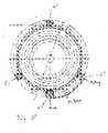
- Fig. 5 shows a schematic plan view of a counter-pressure roller 2, wherein in the lateral surface of the platen 2, the counter cutting strips 61, 62, 63 and 64 parallel to the second axis of rotation B, that is, the axis of rotation of the platen 2, are introduced.
- the distance between the counter cutting strips 61, 62 and 63 to each other is chosen so that they along the circumference of the platen roller 2 are offset by an angle of 120 °.
- the fourth counter-cutting edges 64 are also introduced parallel to the second axis of rotation B in the lateral surface of the platen 2, wherein the fourth counter-cutting bar 64 is offset along the circumference of the platen 2 against the counter-cutting bar 61 by an angle of 180 °.
- the loadable gripper cylinders 7 may be those which either two corresponding to the circumference of the platen 2 labels, or three two-fold the circumference of the platen 2 corresponding, or four one and a half times the circumference of the platen 2 corresponding, or six times the Einrittelfachen circumference of the platen 2 can record appropriate labels.
- Fig. 5 For each counter cutting edge 61, 62, 63 and 64, the various widths of about 7 mm and about 13 to 14 mm are shown, and it is a label with beginning and end of the platen 2 indicated to the position of the label in the to clarify various broad bars.
- the narrow design of the counter cutting strips 61, 62, 63 and 64 according to the counter cutting strip 6a of Fig. 4 is in Fig. 5 designated by a *, whereas the wider version of the counter cutting strips 61, 62, 63 and 64 according to the counter cutting bar 6 of Fig. 4 , and thus according to the present embodiment, is in Fig. 5 denoted by dotted lines.
- control device can control the cutting device 1 in such a way that an offset of the rotational position of the counterpressure roller 2 relative to this starting position of the cutting device 1 results in the rotational position of the cutting element 3.
- This offset can be realized with a corresponding control of the servo drive devices of the counter-pressure roller 2 and the cutting element 3 by the control device.
- the rotational movement of the platen roller 2 and the cutting element 3 offset in time that is, one after the other, to control, so that the cutting element 3 relative to the conventional cutting device 1 moves slightly offset from the platen 2.
- the control device can make the control of the platen roller 2 in time after the cutting element 3 or it can also make the control of the cutting element 3 in time after the platen 2. That is, the cutting position at which the cutting element 3 contacts the counter cutting bar 6 when the label is cut is shifted from the label tape in the direction of the width of the counter cutting strip 6 before cutting a label.
- the cutting position of the label of the label tape is no longer at the predetermined position of the width of the counter-cutting bar 6, for example in the middle of the width of the counter-cutting bar 6, but at a different position, that is, before or after the predetermined position
- an offset of the cutting position on the counter-cutting bar 6 can be achieved as needed, that is, depending on the existing label length.
- the second embodiment is identical to the first embodiment except for the achievement of the displacement of the cutting position. Therefore, only the parts other than the first embodiment of the second embodiment will be described below. The same and equally important parts are provided with the same reference numerals.
- the drive device 5 changes the peripheral speed of the cutting element 3 at least temporarily with respect to the peripheral speed of the counterpressure roller 2.
- the drive device of the counterpressure roller 2 not shown, can change the peripheral speed of the counterpressure roller 2 at least temporarily relative to the peripheral speed of the cutting element 3.
- the third embodiment is identical to the first embodiment except for the provision of the displacement of the cutting position. Therefore, only the parts other than the first embodiment of the third embodiment will be described below. The same and equally important parts are provided with the same reference numerals.
- the cutting position is shifted by the drive means 5, the peripheral speed of the cutting element 3 with respect to the peripheral speed of the platen roller 2 temporarily slowed down or accelerated.
- the fourth embodiment is identical to the first embodiment except for the provision of the displacement of the cutting position. Therefore, in the following, only the parts other than the first embodiment of the fourth embodiment will be described described. The same and equally important parts are provided with the same reference numerals.
- the cutting position is shifted by the non-illustrated drive means of the platen roller 2, the peripheral speed of the platen roller 2 against the peripheral speed of the cutting element 3 slows or accelerates temporarily.
- the fifth embodiment is identical to the first embodiment except for the provision of the displacement of the cutting position. Therefore, only the parts other than the first embodiment of the fifth embodiment will be described below. The same and equally important parts are provided with the same reference numerals.
- the cutting position is shifted by the non-illustrated drive means of the platen roller 2, the supply speed of the label tape against the peripheral speed of the platen 2 and / or the peripheral speed of the cutting element 3 slows or accelerates temporarily.
- the peripheral speed of the cutting tool 4 in the rotating cutting element 3 may be equal to the peripheral speed of the counter-pressure roller 2.
- the execution of the width of the counter cutting strips 61, 62, 63 and 64 in Fig. 4 is modifiable such that all counter cutting strips 61, 62, 63 and 64 have the same width of about 12 to 18 mm and preferably about 13 to 14 mm or only one of them can have a width of about 12 to 18 mm and preferably about 13 to 14 mm.
- the width of the counter cutting strips 61, 62, 63 and 64 may also be greater, as long as the width of the counter cutting strips 61, 62, 63 and 64 is smaller than the length of the counter cutting strips 61, 62, 63 and 64 to the manufacturing cost of Counter cutting bar (s) and thus the cutting device is not unnecessarily increase.
- the equipment of the cutting element 3 and the counter-pressure roller 2, each with its own drive has the advantage that as flexible as possible adapted to the present situation cutting process can be used. If e.g. the cutting element 3 has two cutting tools 4, but one is no longer usable by wear, so it is possible to rotate the cutting element 3 from one to the next cut by 360 °, so that the no longer usable cutting tool 4 is no longer used. This is advantageous because then a change of the cutting element 3 or the no longer useful cutting tool 4 can be made when the machine is serviced at a normal maintenance. Additional interruptions can thus be minimized to a necessary level.
- the peripheral speeds of the cutting element 3 and the counterpressure roller 2 which may well differ during one revolution, are adapted to one another in such a way that they are identical at the time of the cutting of the label. That is, the peripheral speed of the cutter element 3 or the platen roller 2 is slowed or accelerated temporarily before, but not during the cutting of, the label, relative to the peripheral speed of the other rotatable member.
- the openings 65 in the counter-pressure roller 2 and the openings 66 in the counter-cutting bar 6 can be created for example by means of a bore or with a punching or milling tool. Although the openings 65 and 66 are shown in the figures as a round hole or round opening and any other type of opening is suitable, which the above-described function of the openings 65 in counter-pressure roller 2 and the openings 66 in Counter cutting bar 6 can meet, such as a slot, a triangular opening, a star-shaped opening, etc.
- a counter-pressure roller 2 which has a plurality of counter cutting strips 6, not all counter cutting strips 6 must have openings 66. However, it is advantageous if the counter cutting strips 6 are introduced into the lateral surface of the counterpressure roller 2 in such a way that they do not protrude from the roller surface or the lateral surface of the counterpressure roller 2 also has a flat outer surface with the countercut edges 6 introduced.
Abstract
Description
Die Erfindung betrifft eine Schneideinrichtung und ein Schneidverfahren zum Schneiden von Etiketten sowie eine Etikettiervorrichtung, die mit dieser Schneideinrichtung ausgestattet ist.The invention relates to a cutting device and a cutting method for cutting labels as well as to a labeling device equipped with this cutting device.
Eine Etikettiervorrichtung wird zum Versehen von Gegenständen, wie beispielsweise Flaschen, Konservendosen usw., mit einem Etikett verwendet. Hierzu werden in der Etikettiervorrichtung Etiketten von einer Etikettenrolle, welche mit mehreren Etiketten versehen ist, die in Richtung eines Aufrollens bzw. Abrollens der Endlosrolle hintereinander angeordnet sind, mittels einer Schneideinrichtung abgetrennt und dann an den zu etikettierenden Gegenständen angebracht.A labeling device is used to coat items, such as bottles, cans, etc., with a label. For this purpose, in the labeling device labels from a label roll, which is provided with a plurality of labels, which are arranged in the direction of a rolling or unwinding of the endless roll behind one another, separated by means of a cutting device and then attached to the articles to be labeled.
Aus der
Zudem sind bei dem rotierenden Trennelement oftmals mindestens zwei Schneidmesser zum Durchtrennen des Etiketts vorgesehen, da auf diese Weise die Rotationsgeschwindigkeit des Trennelements bei gleicher Leistung der Etikettiervorrichtung gesenkt werden kann. Bei mehr als zwei Schneidmessern muss nämlich das Trennelement von einem Etikettenschnitt zum nächsten keine 360°-Drehung ausführen, sondern bei zwei Schneidmessern ist nur eine Rotation von 180° und bei vier Schneidmessern nur eine Rotation von 90° Grad erforderlich.In addition, at least two cutting blades for severing the label are often provided in the rotating separating element, since in this way the rotational speed of the separating element can be lowered with the same power of the labeling. For more than two cutting blades, the separator does not need to make 360 ° turns from one label cut to the next, but two cutters require only 180 ° rotation and four cutters require only 90 ° rotation.
An der rotierenden Vakuumwalze sind ebenfalls vorzugsweise mindestens zwei Gegenschneidleisten vorhanden, an denen das Schneidmesser den Schnitt durch die Etikettenrolle durchführen kann. Es können auch beispielsweise drei oder vier Gegenschneidleisten mit einem gleichen Abstand untereinander oder mit verschiedenen Abständen vorgesehen sein. Beispielsweise ist auch eine Anordnung der Gegenschneidleisten möglich, bei welchen die Gegenschneidleisten jeweils einen Abstand von 60 ° zueinander haben.At least two counter cutting strips are also preferably present on the rotating vacuum roll, at which point the cutting knife can cut through the label roll. It is also possible, for example, to provide three or four counter cutting bars with an equal spacing from one another or at different distances. For example, an arrangement of the counter cutting strips is possible in which the counter cutting strips each have a distance of 60 ° to each other.
Bei diesem Stand der Technik besteht jedoch das Problem, dass bei einer für die Abmessungen der jeweiligen Vakuumwalze ungünstigen Etikettenlänge der Etikettenanfang genau auf einer Gegenschneidleiste liegt und nicht über Vakuum gehalten werden kann. Dies führt nach dem internen Stand der Technik der Anmelderin bislang dazu, dass diese Gegenschneidleiste ausgebaut werden muss und eine in die Aussparung der Gegenschneidleiste in der Vakuumwalze passende Leiste mit Öffnungen eingesetzt werden muss, um an der Stelle der Leiste über die Öffnungen mittels der Vakuumwalze ein Vakuum zu erzeugen. Solche Leisten mit Öffnungen sind derzeit von dem Benutzer der Etikettiermaschine bzw. der Schneideinrichtung selbst herzustellen, was jedoch schwierig ist, da die Öffnungen schräg zu der Oberfläche der Leiste angesetzt werden müssen und ein zum Erstellen der Öffnungen beispielsweise verwendeter Bohrer leicht abbrechen kann. Soll bei einer derart umgerüsteten Vakuumwalze später wieder an der Stelle, an der die umgerüstete Leiste eingebaut wurde, ein Schneiden der Etikettenrolle stattfinden, ist derzeit die umgerüstete Leiste wieder auszubauen und es ist die ursprünglich vorhandene Gegenschneidleiste einzubauen.In this prior art, however, there is the problem that at an unfavorable for the dimensions of the respective vacuum roll label length of the label start is exactly on a counter-cutting bar and can not be held by vacuum. This leads according to the internal state of the art of the Applicant so far that this counter cutting strip must be removed and a suitable in the recess of the counter cutting strip in the vacuum roll bar with openings must be used to at the location of the bar on the openings by means of the vacuum roller Create vacuum. Such lasts with openings are currently to be made by the user of the labeling or the cutter itself, which is difficult, however, since the openings must be made obliquely to the surface of the bar and easily break off a drill used for creating the openings, for example. Should be in such a converted vacuum roller later again at the point at which the converted bar was installed, take place a cutting of the label roll, currently is the converted bar again expand and it is the originally existing counter cutting bar installed.
Daraus ergibt sich, dass abhängig von der Länge der Etiketten ein erheblicher Umrüstaufwand für den Benutzer der Etikettiermaschine bzw. der Schneideinrichtung entsteht, der sich aufgrund von Zeit- und Kostenaspekten bei einer Etikettierung von Gegenständen als nachteilig erweist.It follows that, depending on the length of the labels, a considerable conversion effort for the user of the labeling machine or the cutting device arises, which proves to be disadvantageous due to time and cost aspects in a labeling of objects.
Zudem ist der beschriebene Austausch der ursprünglich vorhandenen Gegenschneidleiste durch eine mit Öffnungen versehene Leiste bei neueren Schneideinrichtungen nicht möglich, da die neueren Schneideinrichtungen Fertigungstoleranzen erfordern, die bei einem Ausbau und Wiedereinbau der ursprünglich vorhandenen Gegenschneidleiste durch den Benutzer nicht eingehalten werden können. Bei neueren Schneideinrichtungen kann sich der Benutzer also nicht einmal mit der zuvor beschriebenen Umrüstung der Etikettiervorrichtung behelfen, so dass die neuere Schneideinrichtung bei einer für die Abmessungen der jeweiligen Vakuumwalze ungünstigen Etikettenlänge nicht verwendbar ist.In addition, the described replacement of the originally existing counter-cutting bar is not possible with an apertured bar with newer cutting devices, since the newer cutting devices require manufacturing tolerances that can not be met by a removal and replacement of the original counter cutting strip by the user. In the case of newer cutting devices, the user can not even make do with the previously described conversion of the labeling device, so that the newer cutting device can not be used at a label length that is unfavorable for the dimensions of the respective vacuum roller.
Es wurde außerdem bereits überlegt, die Vakuumwalzen derart zu verändern, dass mehr Öffnungen bzw. Vakuumöffnungen in der Walzenfläche der Vakuumwalze vorhanden sind. Das heißt, es wurde überlegt, die in Reihen senkrecht zu der Achse der Vakuumwalze angeordneten Öffnungen bzw. Vakuumöffnungsreihen in der Vakuumwalze mit einem engeren Lochabstand von Vakuumöffnungsreihe zu Vakuumöffnungsreihe anzuordnen. Je mehr Öffnungen jedoch in der Vakuumwalze vorhanden sind, desto länger wird die Reinigungszeit der Schneideinrichtung, was einen längeren Maschinenstillstand zur Folge hat. Zudem kann bei einer solchen Variante nicht das Problem gelöst werden, dass bei einer ungünstigen Etikettenlänge der Etikettenanfang genau auf der Gegenschneidleiste oder neben einer Vakuumöffnung liegt.In addition, it has already been considered to change the vacuum rolls in such a way that more openings or vacuum openings are present in the roll surface of the vacuum roll. That is, it has been considered to arrange the openings or vacuum opening rows arranged in rows perpendicular to the axis of the vacuum roller in the vacuum roller with a closer hole distance from vacuum opening row to vacuum opening row. However, the more openings are present in the vacuum roll, the longer the cleaning time of the cutting device, which has a longer machine downtime result. In addition, in such a variant, the problem can not be solved that with an unfavorable label length of the label start is exactly on the counter cutting bar or next to a vacuum opening.
Daher ist es Aufgabe der Erfindung, eine Schneidvorrichtung und ein Schneidverfahren zum Schneiden von Etiketten sowie eine Etikettiervorrichtung zur Verfügung zu stellen, mit welchen Etiketten mit beliebigen Längen ohne aufwändige Umrüstung der Schneidvorrichtung und/oder Verminderung des Durchsatzes der Schneideinrichtung und damit der Etikettiervorrichtung geschnitten werden können.It is therefore an object of the invention to provide a cutting device and a cutting method for cutting labels and a labeling available with which labels with any length without costly conversion of the cutting device and / or reducing the throughput of the cutting device and thus the labeling can be cut ,
Die Aufgabe wird durch eine Schneideinrichtung zum Schneiden von Etiketten nach Patentanspruch 1, eine Etikettiervorrichtung nach Patentanspruch 14, und zudem ein Schneidverfahren nach Patentanspruch 15 gelöst.The object is achieved by a cutting device for cutting labels according to
Die Schneideinrichtung weist ein Schneidelement und eine Gegendruckwalze auf. Das Schneidelement dient zum Schneiden eines Etikettenbands, welches mit mehreren Etiketten versehen ist, die in Richtung der Länge des Etikettenbands hintereinander angeordnet sind, in einzelne Etiketten, wobei das Schneidelement ein Schneidwerkzeug parallel zu einer ersten Achse aufweist, um welche das Schneidelement drehbar ist. Die Gegendruckwalze dient zum Auflegen des Etikettenbands, wobei die Gegendruckwalze um eine zweite Achse drehbar ist, die parallel zu der ersten Achse angeordnet ist, und weist mindestens eine Gegenschneidleiste auf, die an der Mantelfläche der Gegendruckwalze im Wesentlichen parallel zu der zweiten Achse vorgesehen ist. Hierbei hat die mindestens eine Gegenschneidleiste eine Breite senkrecht zu der zweiten Achse, die kleiner als die Länge der Gegenschneidleiste parallel zu der zweiten Achse ist. Zudem hat die mindestens eine Gegenschneidleiste eine derartige Breite, dass die Schnittposition, bei welcher das Schneidelement die Gegenschneidleiste beim Schneiden des Etiketts kontaktiert, auf der Gegenschneidleiste verschiebbar ist.The cutting device has a cutting element and a counter-pressure roller. The cutting element is for cutting a label tape which is provided with a plurality of labels which are arranged one behind the other in the direction of the length of the label strip, wherein the cutting element has a cutting tool parallel to a first axis about which the cutting element is rotatable. The counter-pressure roller is used for laying the label strip, wherein the counter-pressure roller is rotatable about a second axis, which is arranged parallel to the first axis, and has at least one counter-cutting bar, which is provided on the lateral surface of the counter-pressure roller substantially parallel to the second axis. Here, the at least one counter-cutting bar has a width perpendicular to the second axis, which is smaller than the length of the counter-cutting bar parallel to the second axis. In addition, the at least one counter-cutting bar has a width such that the cutting position at which the cutting element contacts the counter-cutting bar when the label is cut is displaceable on the counter-cutting bar.
Die Etikettiervorrichtung verfügt über eine derartige Schneideinrichtung und dient zum Anbringen der durch die Schneideinrichtung geschnittenen Etiketten an mit Etiketten zu versehenden Gegenständen.The labeling device has such a cutting device and is used for attaching the cut by the cutting device labels to be provided with labels items.
Insbesondere die veränderte Breite der Gegenschneidleiste bei der Schneideinrichtung steht in Kontrast zu der bisherigen Herangehensweise, die Gegenschneidleiste zur Minimierung der Herstellungskosten möglichst schmal zu halten.In particular, the changed width of the counter-cutting bar in the cutting device is in contrast to the previous approach, the counter-cutting bar to minimize the manufacturing costs as narrow as possible.
Vorteilhafte Ausgestaltungen der Schneideinrichtung sind in den abhängigen Patentansprüchen angegeben.Advantageous embodiments of the cutting device are specified in the dependent claims.
Vorzugsweise hat die Gegendruckwalze eine Vielzahl von Öffnungen in der Mantelfläche der Gegendruckwalze zur Erzeugung eines Unterdrucks in der Gegendruckwalze, wenn die Öffnungen zumindest teilweise durch das Etikettenband abgedeckt sind. Hierbei sind die Öffnungen in der Gegendruckwalze vorteilhaft in mehreren parallel zueinander angeordneten Reihen angeordnet, die im Wesentlichen senkrecht zu den Gegenschneidleisten an der Fläche der Gegendruckwalze angeordnet sind. Die Anordnung dieser Öffnungen könnte jedoch auch anders gestaltet sein, etwa in Form von nicht genau parallelen Reihen.Preferably, the counter-pressure roller has a plurality of openings in the lateral surface of the counter-pressure roller for generating a negative pressure in the counter-pressure roller when the openings are at least partially covered by the label tape. In this case, the openings in the counter-pressure roller are advantageously arranged in a plurality of mutually parallel Rows arranged, which are arranged substantially perpendicular to the counter-cutting strips on the surface of the counter-pressure roller. However, the arrangement of these openings could also be designed differently, for example in the form of not exactly parallel rows.
Es ist vorteilhaft, wenn zumindest eine der mindestens einen Gegenschneidleiste eine Vielzahl von Öffnungen aufweist, welche mit Öffnungen in der Fläche der Gegendruckwalze derart in Verbindung stehen, dass ein auf der Gegenschneidleiste aufliegendes Etikettenband bei Erzeugung eines Unterdrucks durch die Gegendruckwalze an der Gegenschneidleiste gehalten wird.It is advantageous if at least one of the at least one counter cutting strip has a multiplicity of openings which are connected to openings in the surface of the counterpressure roller in such a way that a label strip resting on the counter cutting strip is held against the counter cutting strip when a negative pressure is generated by the counterpressure roller.
Hierbei kann die Vielzahl von Öffnungen der Gegenschneidleiste in einer Reihe entlang der Länge der Gegenschneidleiste und im Wesentlichen in der Mitte der Breite der Gegenschneidleiste angeordnet sein.Here, the plurality of openings of the counter-cutting bar can be arranged in a row along the length of the counter-cutting bar and substantially in the middle of the width of the counter-cutting bar.
Vorzugsweise ist Schneideinrichtung derart ausgestaltet ist, dass die Schnittposition auf der Gegenschneidleiste derart verschiebbar ist, dass der Etikettenanfang eines Etiketts auf dem Etikettenband derart platziert werden kann, dass die Vielzahl von Öffnungen im äußeren Bereich des Etikettes angeordnet ist.Preferably, the cutting device is configured such that the cutting position on the counter-cutting bar is displaceable such that the label start of a label can be placed on the label tape such that the plurality of openings in the outer region of the label is arranged.
Die Schneideinrichtung kann auch derart ausgestaltet sein, dass sie durch eine Steuereinrichtung steuerbar ist, welche zur Verschiebung der Schnittposition auf der Gegenschneidleiste derart ausgestaltet ist, dass sie die Drehstellung von Gegendruckwalze und Schneidelement zueinander von einer Ausgangsdrehstellung, bei welcher ein Schneidwerkzeug beim Kontakt mit einer Gegenschneidleiste der Gegendruckwalze immer auf einer vorgegebenen Position der Breite der Gegenschneidleiste auftrifft, in eine andere Drehstellung zueinander versetzt.The cutting device can also be configured such that it is controllable by a control device which is designed to move the cutting position on the counter-cutting bar such that they the rotational position of the platen roller and cutting element to each other from a starting rotational position, in which a cutting tool in contact with a counter cutting bar the counter-pressure roller always impinges on a predetermined position of the width of the counter-cutting bar, offset in another rotational position to each other.
Die Schnittposition kann durch eine Antriebseinrichtung verschiebbar sein, die zur zumindest zeitweisen Änderung einer Umfangsgeschwindigkeit wenigstens eines sich drehenden Elements, welches das Schneidelement oder die Gegendruckwalze ist, gegenüber dem jeweils anderen sich drehenden Element ausgestaltet ist.The cutting position may be displaceable by a drive device which is designed to at least temporarily change a peripheral speed of at least one rotating element, which is the cutting element or the counter-pressure roller relative to the respective other rotating element.
Die Schnittposition kann auch durch eine Antriebseinrichtung verschiebbar sein, die zur zumindest zeitweisen Verlangsamung oder Beschleunigung der Umfangsgeschwindigkeit des Schneidelements gegenüber der Umfangsgeschwindigkeit der Gegendruckwalze ausgestaltet ist.The cutting position may also be displaceable by a drive device, which at least temporarily slowing down or accelerating the peripheral speed of Cutting elements against the peripheral speed of the platen roller is configured.
Ferner kann die Schnittposition durch eine Antriebseinrichtung verschiebbar sein, die zur zumindest zeitweisen Verlangsamung oder Beschleunigung der Umfangsgeschwindigkeit der Gegendruckwalze gegenüber der Umfangsgeschwindigkeit des Schnittelements ausgestaltet ist.Furthermore, the cutting position can be displaced by a drive device, which is designed for at least temporary slowing or acceleration of the peripheral speed of the counter-pressure roller relative to the peripheral speed of the cutting element.
Es ist außerdem möglich, die Schnittposition durch eine Antriebseinrichtung zu verschieben, die zur zumindest zeitweisen Veränderung der Zufuhrgeschwindigkeit des Etikettenbandes gegenüber der Umfangsgeschwindigkeit der Gegendruckwalze und/oder der Umfangsgeschwindigkeit des Schnittelements ausgestaltet ist.It is also possible to shift the cutting position by a drive device which is designed for at least temporary variation of the supply speed of the label strip relative to the peripheral speed of the counter-pressure roller and / or the peripheral speed of the cutting element.
Die Gegenschneidleiste kann vorzugsweise eine Breite von 5 - 20 mm, vorzugsweise von 13 bis 14 mm, haben.The counter cutting bar may preferably have a width of 5 to 20 mm, preferably 13 to 14 mm.
Das Schneidverfahren dient zum Schneiden von Etiketten mit einem Schneidelement, das ein Etikettenband, welches mit mehreren Etiketten versehen ist, die in Richtung der Länge des Etikettenbands hintereinander angeordnet sind, in einzelne Etiketten schneidet, wobei das Schneidelement ein Schneidwerkzeug parallel zu einer ersten Achse aufweist, um welche das Schneidelement gedreht wird, und wobei das Schneidwerkzeug beim Schneiden des Etikettenbands eine Gegenschneidleiste einer Gegendruckwalze kontaktiert, auf welche das Etikettenband aufgelegt ist, wobei die Gegendruckwalze um eine zweite Achse gedreht wird, die parallel zu der ersten Achse angeordnet ist, und mindestens eine Gegenschneidleiste aufweist, die an der Mantelfläche der Gegendruckwalze im Wesentlichen parallel zu der zweiten Achse und bevorzugt in der zweiten Achse vorgesehen ist, wobei die mindestens eine Gegenschneidleiste eine Breite senkrecht zu der zweiten Achse hat, die kleiner als die Länge der Gegenschneidleiste parallel zu der zweiten Achse ist. Hierbei wird die Schnittposition, bei welcher das Schneidelement die Gegenschneidleiste beim Schneiden des Etiketts kontaktiert, vor dem Schneiden des Etikettenbands in einzelne Etiketten auf der Breite der Gegenschneidleiste verschoben.The cutting method is for cutting labels with a cutting element which cuts a label tape provided with a plurality of labels arranged one after the other in the direction of the length of the label tape into individual labels, the cutting element having a cutting tool parallel to a first axis, around which the cutting element is rotated, and wherein the cutting tool when cutting the label strip contacts a counter cutting strip of a counter-pressure roller on which the label tape is placed, wherein the counter-pressure roller is rotated about a second axis, which is arranged parallel to the first axis, and at least one Counter-cutting bar, which is provided on the lateral surface of the counter-pressure roller substantially parallel to the second axis and preferably in the second axis, wherein the at least one counter-cutting bar has a width perpendicular to the second axis, which is smaller than the length of the counter-cutting bar is parallel to the second axis. In this case, the cutting position at which the cutting element contacts the counter-cutting bar when cutting the label, before cutting the label tape into individual labels on the width of the counter-cutting bar is moved.
Durch die Gegenschneidleisten, die gegenüber dem Stand der Technik breiter ausgeführt sind, kann der ganze Bereich der Gegenschneidleiste zum "Schneiden" bzw. Trennen des Etiketts von dem Etikettenband verwendet werden. Durch Verschieben der Schnittposition auf der Gegenschneidleiste, wie zuvor beschrieben, wird stets ein sicherer Halt des Etikettenanfangs gewährleistet. Zudem kann die Umrüstzeit und damit die Stillstandzeit einer Etikettiervorrichtung verringert werden, die mit der beschriebenen Schneideinrichtung ausgestattet ist. Dadurch können Kosten und Zeit eingespart werden.Due to the counter cutting strips, which are made wider compared to the prior art, the whole area of the counter cutting strip for "cutting" or separating the Labels are used by the label tape. By shifting the cutting position on the counter cutting bar, as described above, a secure hold of the label start is always guaranteed. In addition, the changeover time and thus the downtime of a labeling can be reduced, which is equipped with the cutting device described. This can save costs and time.
Nachfolgend wird die Erfindung unter Bezugnahme auf die beiliegende Zeichnung und anhand von Ausführungsbeispielen näher beschrieben. Es zeigen:
- Fig. 1
- eine schematische Draufsicht auf eine Etikettiermaschine;
- Fig. 2
- eine schematische Draufsicht auf eine Schneideinrichtung einer solchen Etikettier- maschine;
- Fig. 3
- eine schematische perspektivische Ansicht der Schneideinrichtung;
- Fig. 4
- eine dreidimensionale Ansicht einer Gegendruckwalze der Schneideinrichtung; und
- Fig. 5
- eine schematische Draufsicht auf die Gegendruckwalze der Schneideinrichtung.
- Fig. 1
- a schematic plan view of a labeling machine;
- Fig. 2
- a schematic plan view of a cutting device of such a labeling machine;
- Fig. 3
- a schematic perspective view of the cutting device;
- Fig. 4
- a three-dimensional view of a counter-pressure roller of the cutting device; and
- Fig. 5
- a schematic plan view of the counter-pressure roller of the cutting device.
Die Etikettiermaschine verfügt über einen Zulaufförderer 24, ein Einlaufsternrad 25 mit vorgeordneter Einteilschnecke 23, einen Führungsbogen 22, ein Karussell 27 mit einer Vielzahl von in gleichmäßigen Abständen auf einem gemeinsamen Teilkreis angeordneten Drehtellern 26, ein Auslaufsternrad 8 und einen Auslaufförderer 9. Die genannten, die Flaschen 10 durch die Maschine bewegenden Transportelemente sind geschwindigkeits- und stellungssynchron zueinander kontinuierlich antreibbar.The labeling machine has a
Im Umlaufbereich zwischen dem Einlaufsternrad 25 und dem Auslaufsternrad 8 befindet sich an der äußeren Peripherie des Karussells 27 ein Etikettieraggregat 12 zum Aufbringen von Rundumetiketten. Das Etikettieraggregat 12 verfügt über zwei Etikettenrollenaufnahmen 14 mit einer dazwischenliegenden Anspleißstation 15, eine Schneideinrichtung 1, ein Leimwerk 17 und einen Greiferzylinder 7 zum Übertragen eines vorgeschnittenen, an seiner vor- und nachlaufenden Kante beleimten Etiketts auf eine vorbeilaufende Flasche 10.In the circulation area between the
Der Etikettiervorgang einer Flasche 10 mit der Etikettiermaschine von
Eine vom Zulaufförderer 24 herangeführte Flasche 10 wird in Verbindung mit der seitlich angeordneten Einteilschnecke 23 stellungsgerecht in das Einlaufsternrad 25 eingeführt und von diesem in Zusammenarbeit mit dem gegenüberliegenden Führungsbogen 22 in kontinuierlicher Bewegung auf einen Drehteller 26 des rotierenden Karussells 27 übergeschoben. Dort wird die Flasche 10 von einer nicht dargestellten, relativ zum Drehteller 26 gesteuerten heb- und senkbaren Zentrierglocke axial auf dem Drehteller 26 mit diesem drehbar eingespannt und durch die Umlaufbewegung des Karussells 27 tangential an den Greiferzylinder 17 des Etikettieraggregats 12 herangeführt.A brought up by the
Dazu zeitlich parallel verlaufend wird von einer von Etikettenbandrollen 14 das Etikettenband gesteuert abgezogen und an einem hier nicht gezeigten Druckmarken bzw. Druckbild erkennenden Sensor vorbeigeführt und in der mit dem Sensor verbundenen Schneideinrichtung 1 dem Druckbild bzw. den Schnittmarken entsprechend geschnitten. Das abgetrennte Etikett, das sich während des Schneidvorgangs mit dem Druckbild nach außen auf einer rotierenden Gegendruckwalze 2 befindet, wird nach dem Trennvorgang an den mit Vakuum betriebenen Greiferzylinder 7 übergeben, von wo aus es an der Leimwalze 18 mit der Rückseite nach außen vorbeigeführt und mit je einem Leimstreifen am Anfang und am Ende versehen wird. Dieses mit dem Anfangs- bzw. Endleimstreifen versehene Etikett wird tangential dem Karussell 27, auf dem sich die Flaschen 10 befinden, zugeführt. Der Anfangsleimstreifen wird mit der Flasche 10 in Berührung gebracht und durch Drehung der Flasche 10 um ihre eigene Achse wird das Etikett aufgewickelt, wobei der Endleimstreifen entweder überlappend oder Kante an Kante mit dem Anfang des Etiketts verklebt wird. Das geschilderte Anbringen des Etiketts erfolgt während einer kontinuierlichen Vorwärtsbewegung des Karussells 27.For this purpose, running in parallel, the label strip is withdrawn in a controlled manner from a
Nach dem Passieren des Etikettieraggregats 12 und nach Abschluss des Aufwickelvorgangs erreicht die etikettierte Flasche 10 im weiteren Verlauf das Auslaufsternrad 8 und wird an den Auslaufförderer 9 übergeben.After passing through the
Wie in
Die Anordnung der Reihen der Öffnungen 65 ist auch wählbar, wie in
In
Die untere Gegenschneidleiste 6a in
Die obere Gegenschneidleiste 6 in
In
Es ist darauf hinzuweisen, dass die Gegenschneidleiste 6 üblicherweise auf der gesamten Breite der Gegendruckwalze 2 vorhanden ist, und nicht wie in
In
Die Verschiebung der Schnittposition auf der Gegenschneidleiste 6 bzw. den Gegenschneidleisten 61, 62, 63 und 64, das heißt auf der Gegenschneidleiste gemäß dem vorliegenden Ausführungsbeispiel mit einer Breite von ca. 12 bis 18 mm und bevorzugt 13 bis 14 mm, kann mittels einer nicht dargestellten Steuereinrichtung verschoben werden, welche die Schneideinrichtung 1 steuert. Das heißt, die Steuereinrichtung kann die Drehstellung von Gegendruckwalze 2 und Schneidelement 3 zueinander steuern. Genauer gesagt, die Drehstellung von Gegendruckwalze 2 und Schneidelement 3 zueinander ist in einer Ausgangsstellung der Schneideinrichtung 1 derart eingestellt, dass ein Schneidwerkzeug 4 des Schneidelements 3 beim Kontakt mit einer Gegenschneidleiste 6 immer auf einer vorgegebenen Position der Breite der Gegenschneidleiste 6 auftrifft.The displacement of the cutting position on the
Gemäß diesem Ausführungsbeispiel kann die Steuereinrichtung die Schneideinrichtung 1 derart ansteuern, dass sich gegenüber dieser Ausgangsstellung der Schneideinrichtung 1 ein Versatz der Drehstellung von Gegendruckwalze 2 zu der Drehstellung des Schneidelements 3 ergibt.According to this exemplary embodiment, the control device can control the
Dieser Versatz kann mit einer entsprechenden Ansteuerung der Servoantriebseinrichtungen der Gegendruckwalze 2 und des Schneidelements 3 durch die Steuereinrichtung realisiert werden.This offset can be realized with a corresponding control of the servo drive devices of the
Es ist auch möglich, die Drehbewegung der Gegendruckwalze 2 und des Schneidelement 3 zeitlich versetzt, das heißt zeitlich nacheinander, anzusteuern, so dass sich das Schneidelement 3 gegenüber der herkömmlichen Schneideinrichtung 1 etwas versetzt zu der Gegendruckwalze 2 bewegt. Die Steuereinrichtung kann die Steuerung der Gegendruckwalze 2 zeitlich nach dem Schneidelement 3 vornehmen oder sie kann auch die Steuerung des Schneidelements 3 zeitlich nach der Gegendruckwalze 2 vornehmen. Das heißt, die Schnittposition, bei welcher das Schneidelement 3 die Gegenschneidleiste 6 beim Schneiden des Etiketts kontaktiert, wird vor dem Schneiden eines Etiketts von dem Etikettenband in Richtung der Breite der Gegenschneidleiste 6 verschoben.It is also possible, the rotational movement of the
Auf diese Weise liegt bei dem vorliegenden Ausführungsbeispiel die Schnittposition des Etiketts des Etikettenbands nicht mehr bei der vorgegebenen Position der Breite der Gegenschneidleiste 6, beispielsweise in der Mitte der Breite der Gegenschneidleiste 6, sondern an einer anderen Position, das heißt vor oder hinter der vorgegebenen Position der Breite der Gegenschneidleiste 6. Dadurch kann ein Versatz der Schnittposition auf der Gegenschneidleiste 6 je nach Bedarf, das heißt, je nach vorhandener Etikettenlänge erzielt werden.In this way, in the present embodiment, the cutting position of the label of the label tape is no longer at the predetermined position of the width of the
Das zweite Ausführungsbeispiel ist bis auf die Bewerkstelligung der Verschiebung der Schnittposition identisch zu dem ersten Ausführungsbeispiel. Daher werden im Folgenden nur die von dem ersten Ausführungsbeispiel verschiedenen Teile des zweiten Ausführungsbeispiels beschrieben. Gleiche und gleich bedeutende Teile sind mit gleichen Bezugszeichen versehen.The second embodiment is identical to the first embodiment except for the achievement of the displacement of the cutting position. Therefore, only the parts other than the first embodiment of the second embodiment will be described below. The same and equally important parts are provided with the same reference numerals.
Gemäß dem zweiten Ausführungsbeispiel kann die Verschiebung der Schnittposition auf der Gegenschneidleiste 6 bzw. den Gegenschneidleisten 61, 62, 63 und 64 mittels der Antriebseinrichtung 5 des Schneidelements 3 oder der nicht dargestellten Antriebseinrichtung der Gegendruckwalze 2 erfolgen. Das heißt, eine der Antriebseinrichtungen kann die Umfangsgeschwindigkeit des von ihr angetriebenen Elements gegenüber der Umfangsgeschwindigkeit des von der anderen Antriebseinrichtung angetriebenen anderen Elements zumindest zeitweise ändern. Auf diese Weise kann ein Versatz der Schnittposition auf der Gegenschneidleiste 6 je nach Bedarf, das heißt, je nach vorhandener Etikettenlänge erzielt werden.According to the second embodiment, the displacement of the cutting position on the
Insbesondere ändert beispielsweise die Antriebseinrichtung 5 die Umfangsgeschwindigkeit des Schneidelements 3 zumindest zeitweise gegenüber der Umfangsgeschwindigkeit der Gegendruckwalze 2. Es kann aber auch die nicht dargestellte Antriebseinrichtung der Gegendruckwalze 2 die Umfangsgeschwindigkeit der Gegendruckwalze 2 zumindest zeitweise gegenüber der Umfangsgeschwindigkeit des Schneidelements 3 ändern.In particular, for example, the
Das dritte Ausführungsbeispiel ist bis auf die Bewerkstelligung der Verschiebung der Schnittposition identisch zu dem ersten Ausführungsbeispiel. Daher werden im Folgenden nur die von dem ersten Ausführungsbeispiel verschiedenen Teile des dritten Ausführungsbeispiels beschrieben. Gleiche und gleich bedeutende Teile sind mit gleichen Bezugszeichen versehen.The third embodiment is identical to the first embodiment except for the provision of the displacement of the cutting position. Therefore, only the parts other than the first embodiment of the third embodiment will be described below. The same and equally important parts are provided with the same reference numerals.
Gemäß diesem Ausführungsbeispiel wird die Schnittposition verschoben, indem die Antriebseinrichtung 5 die Umfangsgeschwindigkeit des Schneidelements 3 gegenüber der Umfangsgeschwindigkeit der Gegendruckwalze 2 zeitweise verlangsamt oder beschleunigt.According to this embodiment, the cutting position is shifted by the drive means 5, the peripheral speed of the cutting
Das vierte Ausführungsbeispiel ist bis auf die Bewerkstelligung der Verschiebung der Schnittposition identisch zu dem ersten Ausführungsbeispiel. Daher werden im Folgenden nur die von dem ersten Ausführungsbeispiel verschiedenen Teile des vierten Ausführungsbeispiels beschrieben. Gleiche und gleich bedeutende Teile sind mit gleichen Bezugszeichen versehen.The fourth embodiment is identical to the first embodiment except for the provision of the displacement of the cutting position. Therefore, in the following, only the parts other than the first embodiment of the fourth embodiment will be described described. The same and equally important parts are provided with the same reference numerals.
Gemäß diesem Ausführungsbeispiel wird die Schnittposition verschoben, indem die nicht dargestellte Antriebseinrichtung der Gegendruckwalze 2 die Umfangsgeschwindigkeit der Gegendruckwalze 2 gegenüber der Umfangsgeschwindigkeit des Schneidelements 3 zeitweise verlangsamt oder beschleunigt.According to this embodiment, the cutting position is shifted by the non-illustrated drive means of the
Das fünfte Ausführungsbeispiel ist bis auf die Bewerkstelligung der Verschiebung der Schnittposition identisch zu dem ersten Ausführungsbeispiel. Daher werden im Folgenden nur die von dem ersten Ausführungsbeispiel verschiedenen Teile des fünften Ausführungsbeispiels beschrieben. Gleiche und gleich bedeutende Teile sind mit gleichen Bezugszeichen versehen.The fifth embodiment is identical to the first embodiment except for the provision of the displacement of the cutting position. Therefore, only the parts other than the first embodiment of the fifth embodiment will be described below. The same and equally important parts are provided with the same reference numerals.
Gemäß diesem Ausführungsbeispiel wird die Schnittposition verschoben, indem die nicht dargestellte Antriebseinrichtung der Gegendruckwalze 2 die Zufuhrgeschwindigkeit des Etikettenbands gegenüber der Umfangsgeschwindigkeit der Gegendruckwalze 2 und/oder der Umfangsgeschwindigkeit des Schneidelements 3 zeitweise verlangsamt oder beschleunigt.According to this embodiment, the cutting position is shifted by the non-illustrated drive means of the
In diesem Fall kann beispielsweise die Umfangsgeschwindigkeit des Schneidwerkzeugs 4 im rotierenden Schneidelement 3 gleich der Umfangsgeschwindigkeit der Gegendruckwalze 2 sein.In this case, for example, the peripheral speed of the
Wenn die Umfangsgeschwindigkeit der Gegendruckwalze 2 jedoch ungleich der Zufuhrgeschwindigkeit des Etikettenbandes ist, erfolgt der Transport des Etikettenbandes auf der Gegendruckwalze 2 nicht mehr reibschlüssig sondern mit Schlupf.However, if the circumferential speed of the
Alle zuvor beschriebenen Ausgestaltungen der Schneideinrichtung und der Etikettiervorrichtung können einzeln oder in allen möglichen Kombinationen Verwendung finden. Hierbei sind insbesondere folgende Modifikationen denkbar.All of the above-described embodiments of the cutting device and the labeling device can be used individually or in all possible combinations. In particular, the following modifications are conceivable.
Die Ausführung der Breite der Gegenschneidleisten 61, 62, 63 und 64 in
Die Ausstattung des Schneidelements 3 und der Gegendruckwalze 2 mit je einem eigenen Antrieb hat den Vorteil, dass möglichst flexibel ein der vorliegenden Situation angepasstes Schneidverfahren zur Anwendung kommen kann. Wenn z.B. das Schneidelement 3 zwei Schneidwerkzeuge 4 aufweist, eines aber durch Abnutzung nicht mehr brauchbar ist, so ist es möglich, das Schneidelement 3 von einem zum nächsten Schnitt um 360° zu drehen, damit das nicht mehr brauchbare Schneidwerkzeug 4 nicht mehr zum Einsatz kommt. Dies ist vorteilhaft, da dann ein Wechsel des Schneidelements 3 oder des nicht mehr brauchbaren Schneidwerkzeugs 4 vorgenommen werden kann, wenn die Maschine bei einer üblichen Wartung gewartet wird. Zusätzliche Unterbrechungen können somit auf ein notwendiges Maß minimiert werden.The equipment of the cutting
Gemäß einer bevorzugten Modifikation der Erfindung werden die Umfangsgeschwindigkeiten des Schneidelements 3 und der Gegendruckwalze 2, die sich während einer Umdrehung durchaus unterscheiden können, so aufeinander abgestimmt, dass sie sich zum Zeitpunkt des Schneidens des Etiketts gleichen. Das heißt, die Umfangsgeschwindigkeit des Schneidelements 3 oder der Gegendruckwalze 2 wird vor, aber nicht beim Schneiden des Etiketts, zeitweilig gegenüber der Umfangsgeschwindigkeit des anderen drehbaren Elements verlangsamt oder beschleunigt.According to a preferred modification of the invention, the peripheral speeds of the cutting
Die Öffnungen 65 in der Gegendruckwalze 2 und die Öffnungen 66 in der Gegenschneidleiste 6 können beispielsweise mittels einer Bohrung oder mit einem Stanz- oder Fräswerkzeug erstellt werden. Auch wenn die Öffnungen 65 und 66 in den Figuren als Rundloch bzw. runde Öffnung dargestellt sind ist auch jede andere Art von Öffnung geeignet, welche die zuvor beschriebene Funktion der Öffnungen 65 in Gegendruckwalze 2 und die Öffnungen 66 in Gegenschneidleiste 6 erfüllen kann, wie beispielsweise ein Langloch, eine dreieckige Öffnung, eine sternförmige Öffnung usw.The
Bei einer Gegendruckwalze 2, die mehrere Gegenschneidleisten 6 aufweist, müssen nicht alle Gegenschneidleisten 6 Öffnungen 66 aufweisen. Es ist jedoch vorteilhaft, wenn die Gegenschneidleisten 6 so in die Mantelfläche der Gegendruckwalze 2 eingebracht sind, dass sie nicht aus der Walzenoberfläche herausstehen bzw. die Mantelfläche der Gegendruckwalze 2 auch mit den eingebrachten Gegenschneidleisten 6 eine ebene äußere Oberfläche hat.In a
- 11
- Schneideinrichtungcutter
- 22
- GegendruckwalzeBacking roll
- 33
- Schneidelementcutting element
- 44
- Schneidwerkzeugcutting tool
- 55
- Antriebseinrichtung des SchneidelementsDrive device of the cutting element
- 66
- Gegenelement bzw. GegenschneidleisteCounter element or counter cutting strip
- 77
- Greiferzylindergripper cylinder
- 88th
- Auslaufsternradoutput star
- 99
- Auslauffördererexit conveyor
- 1010
- Flaschenbottles
- 1212
- Etikettieraggregatlabeling
- 1414
- EtikettenrollenaufnahmenLabel roll recordings
- 1515
- AnspleißstationAnspleißstation
- 1717
- Leimwerkgluing unit
- 1818
- Leimwalzeglue roller
- 2222
- Führungsbogenguide arch
- 2323
- Einteilschneckeinfeed worm
- 2424
- Zulauffördererfeeder conveyors
- 2525
- Einlaufsternradfeed wheel
- 2626
- Drehtellerturntable
- 2727
- Karussellcarousel
- 3131
- Pfeilarrow
- 3232
- Pfeilarrow
- 61, 62, 63, 6461, 62, 63, 64
- GegenschneidleistenCounter-cutting bars
- 6565
- Öffnungen in GegendruckwalzeOpenings in counterpressure roller
- 6666
- Öffnungen in GegenschneidleisteOpenings in counter cutting bar
- AA
- erste Achsefirst axis
- BB
- zweite Achsesecond axis
Claims (15)
einem Schneidelement (3) zum Schneiden eines Etikettenbands, welches mit mehreren Etiketten versehen ist, die in Richtung der Länge des Etikettenbands hintereinander angeordnet sind, in einzelne Etiketten, wobei das Schneidelement (3) ein Schneidwerkzeug (4) parallel zu einer ersten Achse (A) aufweist, um welche das Schneidelement (3) drehbar ist,
einer Gegendruckwalze (2) zum Auflegen des Etikettenbands, wobei die Gegendruckwalze (2) um eine zweite Achse (B) drehbar ist, die parallel zu der ersten Achse (A) angeordnet ist, und mindestens eine Gegenschneidleiste (6) aufweist, die an der Mantelfläche der Gegendruckwalze (2) im Wesentlichen parallel zu der zweiten Achse (B) vorgesehen ist,
wobei die mindestens eine Gegenschneidleiste (6) eine Breite senkrecht zu der zweiten Achse (B) hat, die kleiner als die Länge der Gegenschneidleiste (6) parallel zu der zweiten Achse (B) ist,
dadurch gekennzeichnet, dass
die mindestens eine Gegenschneidleiste (6) eine derartige Breite hat, dass die Schnittposition, bei welcher das Schneidelement (3) die Gegenschneidleiste (6) beim Schneiden des Etiketts kontaktiert, auf der Gegenschneidleiste (6) verschiebbar ist.Cutting device (1) for cutting labels, with
a cutting element (3) for cutting a label tape provided with a plurality of labels arranged one behind the other in the direction of the length of the label tape, the cutting element (3) comprising a cutting tool (4) parallel to a first axis (A ) about which the cutting element (3) is rotatable,
a counter - pressure roller (2) for laying the label strip, wherein the counter - pressure roller (2) about a second axis (B) is rotatable, which is arranged parallel to the first axis (A), and at least one counter - cutting bar (6) which at the Lateral surface of the counter-pressure roller (2) is provided substantially parallel to the second axis (B),
wherein the at least one counter cutting bar (6) has a width perpendicular to the second axis (B) that is smaller than the length of the counter cutting bar (6) parallel to the second axis (B),
characterized in that
the at least one counter cutting bar (6) has a width such that the cutting position at which the cutting element (3) contacts the counter cutting bar (6) when the label is cut is displaceable on the counter cutting bar (6).
die Gegendruckwalze (2) eine Vielzahl von Öffnungen (65) in der Mantelfläche der Gegendruckwalze (2) zur Erzeugung eines Unterdrucks in der Gegendruckwalze (2) aufweist, wenn die Öffnungen (65) zumindest teilweise durch das Etikettenband abgedeckt sind, und
die Öffnungen (65) in der Gegendruckwalze (2) in mehreren parallel zueinander angeordneten Reihen angeordnet sind, die im Wesentlichen senkrecht zu den Gegenschneidleisten (6) an der Fläche der Gegendruckwalze (2) angeordnet sind.Cutting device according to claim 1, wherein
the counterpressure roller (2) has a multiplicity of openings (65) in the lateral surface of the counterpressure roller (2) for generating a negative pressure in the counterpressure roller (2) when the openings (65) are at least partially covered by the label strip, and
the openings (65) in the counter-pressure roller (2) are arranged in a plurality of mutually parallel rows, which are arranged substantially perpendicular to the counter-cutting bars (6) on the surface of the counter-pressure roller (2).
dadurch gekennzeichnet, dass
die Schnittposition, bei welcher das Schneidelement (3) die Gegenschneidleiste (6) beim Schneiden des Etiketts kontaktiert, vor dem Schneiden des Etikettenbands in einzelne Etiketten auf der Breite der Gegenschneidleiste (6) verschoben wird.A cutting method for cutting labels with a cutting element (3) which cuts a label strip provided with a plurality of labels arranged one behind the other in the direction of the length of the label strip into individual labels, the cutting element (3) comprising a cutting tool (4) in the first axis (A), around which the cutting element (3) is rotated, and wherein the cutting tool (4) when cutting the label strip, a counter cutting strip (6) of a counter-pressure roller (2) contacted, on which the label tape is placed, the counterpressure roller (2) is rotated about a second axis (B), which is arranged parallel to the first axis (A), and has at least one counter cutting strip (6), which on the lateral surface of the counterpressure roller (2) substantially parallel to the second axis (B) is provided, wherein the at least one counter cutting bar (6) has a width perpendicular to the second axis (B), which is smaller than the length of the Gegenschnei dleiste (6) is parallel to the second axis (B),
characterized in that
the cutting position at which the cutting element (3) contacts the counter-cutting strip (6) when the label is cut is cut to the width of the counter-cutting strip (6) before the label strip is cut into individual labels.
Applications Claiming Priority (1)
| Application Number | Priority Date | Filing Date | Title |
|---|---|---|---|
| DE102009035269A DE102009035269A1 (en) | 2009-07-29 | 2009-07-29 | Cutting device and cutting method for cutting labels and labeling device |
Publications (3)
| Publication Number | Publication Date |
|---|---|
| EP2279954A2 true EP2279954A2 (en) | 2011-02-02 |
| EP2279954A3 EP2279954A3 (en) | 2013-05-15 |
| EP2279954B1 EP2279954B1 (en) | 2016-01-06 |
Family
ID=43019110
Family Applications (1)
| Application Number | Title | Priority Date | Filing Date |
|---|---|---|---|
| EP10171094.5A Active EP2279954B1 (en) | 2009-07-29 | 2010-07-28 | Cutting device, method for cutting labels and labelling device |
Country Status (5)
| Country | Link |
|---|---|
| US (1) | US9003935B2 (en) |
| EP (1) | EP2279954B1 (en) |
| JP (1) | JP5675198B2 (en) |
| CN (1) | CN101987665B (en) |
| DE (1) | DE102009035269A1 (en) |
Cited By (4)
| Publication number | Priority date | Publication date | Assignee | Title |
|---|---|---|---|---|
| WO2017205195A1 (en) * | 2016-05-24 | 2017-11-30 | The Procter & Gamble Company | Rotary anvil |
| WO2018226395A1 (en) | 2017-06-06 | 2018-12-13 | Elum Inc. | Systems and methods for cutting label material |
| US11292016B2 (en) | 2018-03-16 | 2022-04-05 | The Procter & Gamble Company | Nozzle assembly used to manufacture absorbent articles |
| WO2022177421A1 (en) * | 2021-02-16 | 2022-08-25 | Vmi Holland B.V. | Applicator unit, tire building device and method for applying a strip to a drum |
Families Citing this family (5)
| Publication number | Priority date | Publication date | Assignee | Title |
|---|---|---|---|---|
| US9902083B2 (en) | 2010-09-30 | 2018-02-27 | The Procter & Gamble Company | Absorbent article substrate trim material removal process and apparatus |
| US20170173812A1 (en) * | 2015-12-16 | 2017-06-22 | Delta Industial Services, Inc. | Apparatus and method for rotary kiss cut liner efficiency |
| MX2019013032A (en) | 2017-05-01 | 2020-02-05 | Avery Dennison Retail Information Services Llc | Method for reducing label waste using a cutting apparatus. |
| DE102018127852A1 (en) * | 2018-11-08 | 2020-05-14 | Khs Gmbh | Cutting unit for a labeling unit and labeling unit with such a cutting unit |
| US11618177B1 (en) | 2022-04-12 | 2023-04-04 | Bradley W Boesel | Orbital knife |
Citations (2)
| Publication number | Priority date | Publication date | Assignee | Title |
|---|---|---|---|---|
| DE202005002793U1 (en) | 2005-02-22 | 2005-04-21 | Krones Ag | Labeling machine for containers such as jars, cans and bottles comprises a cutting unit formed by a rotating vacuum roll and a rotating separation element with at least one separation tool |
| EP2042437A1 (en) | 2007-09-03 | 2009-04-01 | KRONES Aktiengesellschaft | Labelling device |
Family Cites Families (38)
| Publication number | Priority date | Publication date | Assignee | Title |
|---|---|---|---|---|
| US3577293A (en) * | 1962-09-19 | 1971-05-04 | Continental Can Co | Method of labelling cylindrical objects |
| US3565724A (en) | 1967-07-31 | 1971-02-23 | Nishimura Seisakusho Co | Automatic labelling machine |
| US3618483A (en) * | 1970-04-17 | 1971-11-09 | Smithe Machine Co Inc F L | Apparatus for regulating window patch length on envelope and bag machinery |
| US3957570A (en) * | 1971-10-13 | 1976-05-18 | F. L. Smithe Machine Company, Inc. | Machinery for patching envelopes and the like |
| US4108710A (en) * | 1972-02-14 | 1978-08-22 | B & H Manufacturing Company, Inc. | Apparatus for applying labels to containers |
| US4671843A (en) * | 1986-04-28 | 1987-06-09 | Owens-Illinois, Inc. | Label transport vacuum drum |
| JPH03113798A (en) | 1989-09-22 | 1991-05-15 | Sony Corp | Semiconductor memory |
| JPH0735750Y2 (en) * | 1990-03-02 | 1995-08-16 | 株式会社石津製作所 | Rotary shearing type web cutting device |
| JP2542277B2 (en) * | 1990-06-27 | 1996-10-09 | 株式会社フジシール | Label sticking method and device |
| US5363728A (en) * | 1992-10-22 | 1994-11-15 | Elsner Engineering Works, Inc. | Two roll web cutter and method |
| BR9405708A (en) * | 1993-01-07 | 1995-12-19 | R W Packaging Inc | Labeling process system |
| US5413651A (en) * | 1993-03-23 | 1995-05-09 | B&H Manufacturing Company | Universal roll-fed label cutter |
| US5821724A (en) * | 1995-02-03 | 1998-10-13 | Cms Gilbreth Packaging Systems | Feedback limiter for closed loop motor controller |
| JPH0735750A (en) | 1993-07-19 | 1995-02-07 | Tosoh Corp | Improved immunoreaction method |
| DE19518650C1 (en) * | 1995-05-20 | 1996-10-24 | Koenig & Bauer Albert Ag | Cutting device |
| US5863382A (en) * | 1995-09-22 | 1999-01-26 | Trine Manufacturing Company, Inc. | Labeling machine with improved cutter assembly |
| DE69727496T2 (en) | 1996-11-07 | 2004-10-07 | Carmichael Scotland Ltd | LABELING DEVICE WITH LABEL ROLL |
| IT1294078B1 (en) * | 1997-03-18 | 1999-03-22 | Sasib Labelling Spa | LABELING DEVICE IN A LABELING MACHINE WITH CONTINUOUS INTRODUCTION OF A FILM OF LABELS IN REEL. |
| JPH1177586A (en) * | 1997-09-04 | 1999-03-23 | Mitsubishi Heavy Ind Ltd | Rotary cutoff device |
| DE19755058C1 (en) * | 1997-12-11 | 1999-08-12 | Lohmann Therapie Syst Lts | Device with suction openings for transferring flat products to a conveyor belt |
| EP0943404A3 (en) * | 1998-03-17 | 2002-01-02 | Mitsubishi Heavy Industries, Ltd. | Lubricating system for rotary die cutters |
| US6328832B1 (en) * | 1998-06-26 | 2001-12-11 | S-Con, Inc. | Labeling apparatus with web registration, web cutting and carrier mechanisms, and methods thereof |
| US6294038B1 (en) * | 1998-08-05 | 2001-09-25 | Advanced Label Systems, Inc. | Apparatus and method for applying linerless labels |
| US6149755A (en) * | 1998-12-29 | 2000-11-21 | Kimberly-Clark Worldwide, Inc. | Machine and process for placing discrete components on a moving web with velocity matched placement and integral bonding |
| ITPR20000040A1 (en) * | 2000-06-27 | 2001-12-27 | Sasib Labelling Machinery S P | CUTTING ROLL IN A LABELING MACHINE WITH CONTINUOUS INTRODUCTION OF A FILM OF LABELS IN THE REEL |
| ATE380634T1 (en) * | 2000-11-01 | 2007-12-15 | Adalis Corp | FEED SYSTEM FOR WEB-SHAPED MATERIAL AND DEVICE FOR APPLYING WEB-SHAPED MATERIAL |
| US6604623B2 (en) * | 2001-01-31 | 2003-08-12 | Zuiko Corporation | Article transfer apparatus |
| US6742427B2 (en) * | 2001-12-13 | 2004-06-01 | John R. Buta | Helical rotary drum shears |
| ATE359225T1 (en) * | 2002-10-31 | 2007-05-15 | Mtc Macchine Trasformazione | METHOD FOR ACTIVATING SUCTION HOLES OF ROLLERS FOR PAPER PROCESSING MACHINES AND ROLLERS FOR PERFORMING THIS METHOD |
| US7172666B2 (en) * | 2002-12-17 | 2007-02-06 | Groves Matthew E | Web material application methods and systems |
| DE202004013947U1 (en) * | 2004-09-08 | 2005-02-17 | Krones Ag | Article with a labeled lateral surface and device for labeling an article |
| JP2006167945A (en) * | 2004-12-13 | 2006-06-29 | Sugimura Seiko Kk | Sheet laminating type three-dimensional shaping method and apparatus therefor |
| DE102006013844A1 (en) | 2006-03-25 | 2007-10-11 | Khs Ag | Vacuum drum and labeling machine with such a drum for all-round labeling of bottles or similar containers |
| JP4959355B2 (en) * | 2007-01-29 | 2012-06-20 | サントリーホールディングス株式会社 | Conveying drum, labeling container manufacturing method and labeling container manufacturing apparatus |
| DE202007001964U1 (en) | 2007-02-06 | 2007-04-05 | Khs Ag | Labelling device for labelling bottles and containers has drive for vacuum cylinder and/or knife carrier constructed so that at moment of cutting, cutting knife and counter-knife which interacts with it, have same circumferential speed |
| JP5322396B2 (en) * | 2007-03-14 | 2013-10-23 | 全利機械股▲ふん▼有限公司 | A thin paper cutting mechanism with a blade on a spiral curve rotation angle and the structure of the blade |
| DE102007058818A1 (en) * | 2007-12-05 | 2009-06-10 | Krones Ag | Device for cutting strips, especially label strips with roller rotating around rotation axis useful in label production technology decreases cutter wear and gives cleaner cut because of lower label pressure |
| DE102007058816A1 (en) * | 2007-12-05 | 2009-06-10 | Krones Ag | Cutting tool for cutting labels |
-
2009
- 2009-07-29 DE DE102009035269A patent/DE102009035269A1/en not_active Withdrawn
-
2010
- 2010-07-27 JP JP2010167766A patent/JP5675198B2/en active Active
- 2010-07-28 CN CN201010245305.0A patent/CN101987665B/en active Active
- 2010-07-28 US US12/845,495 patent/US9003935B2/en active Active
- 2010-07-28 EP EP10171094.5A patent/EP2279954B1/en active Active
Patent Citations (2)
| Publication number | Priority date | Publication date | Assignee | Title |
|---|---|---|---|---|
| DE202005002793U1 (en) | 2005-02-22 | 2005-04-21 | Krones Ag | Labeling machine for containers such as jars, cans and bottles comprises a cutting unit formed by a rotating vacuum roll and a rotating separation element with at least one separation tool |
| EP2042437A1 (en) | 2007-09-03 | 2009-04-01 | KRONES Aktiengesellschaft | Labelling device |
Cited By (8)
| Publication number | Priority date | Publication date | Assignee | Title |
|---|---|---|---|---|
| WO2017205195A1 (en) * | 2016-05-24 | 2017-11-30 | The Procter & Gamble Company | Rotary anvil |
| WO2018226395A1 (en) | 2017-06-06 | 2018-12-13 | Elum Inc. | Systems and methods for cutting label material |
| EP3634674A4 (en) * | 2017-06-06 | 2021-03-10 | Elum Inc. | Systems and methods for cutting label material |
| US11091288B1 (en) | 2017-06-06 | 2021-08-17 | Elum Inc. | Systems and methods for cutting label material |
| US11292016B2 (en) | 2018-03-16 | 2022-04-05 | The Procter & Gamble Company | Nozzle assembly used to manufacture absorbent articles |
| WO2022177421A1 (en) * | 2021-02-16 | 2022-08-25 | Vmi Holland B.V. | Applicator unit, tire building device and method for applying a strip to a drum |
| NL2027569B1 (en) * | 2021-02-16 | 2022-09-14 | Vmi Holland Bv | Applicator unit, tire building device and method for applying a strip to a drum |
| NL2027569A (en) * | 2021-02-16 | 2022-09-14 | Vmi Holland Bv | Applicator unit, tire building device and method for applying a strip to a drum |
Also Published As
| Publication number | Publication date |
|---|---|
| US20110023671A1 (en) | 2011-02-03 |
| CN101987665B (en) | 2016-03-02 |
| CN101987665A (en) | 2011-03-23 |
| US9003935B2 (en) | 2015-04-14 |
| JP5675198B2 (en) | 2015-02-25 |
| EP2279954A3 (en) | 2013-05-15 |
| DE102009035269A1 (en) | 2011-02-03 |
| EP2279954B1 (en) | 2016-01-06 |
| JP2011045990A (en) | 2011-03-10 |
Similar Documents
| Publication | Publication Date | Title |
|---|---|---|
| EP2279954B1 (en) | Cutting device, method for cutting labels and labelling device | |
| EP1785379B2 (en) | Device for processing and/or conveying a sheet in a rotary printing press | |
| DE3714662C2 (en) | ||
| EP2042437B1 (en) | Labelling device | |
| EP2199084B1 (en) | Device and method for manufacturing book blocks | |
| DE3430739A1 (en) | METHOD FOR CUTTING AND PUNCHING AND DELIVERING STICKERS OF DIFFERENT SHAPES | |
| DE4005028A1 (en) | CUTTER FOR A PRINTER PRESSED WITH A MATERIAL RAIL | |
| EP1640126A1 (en) | Apparatus and method for manufacturing undulated cardboard sheets | |
| DE2902315C2 (en) | Device for labeling containers | |
| DE3711824C2 (en) | ||
| EP1172206B1 (en) | Apparatus for introducing material webs into feed paths of rotary printing machines | |
| DE69933546T2 (en) | PROCESSING OF CUTTING IN THE MANUFACTURE OF PACKAGING | |
| EP0623451A1 (en) | Method for laying a rubberized textile fabric band on a tire building drum and apparatus for carrying out this method | |
| DE2217032C3 (en) | Device for applying blanks made from a continuous web to objects | |
| DE3332992A1 (en) | PRINTER WITH MOSAIC PRINT HEADS | |
| EP0854098B1 (en) | Package for a group of cigarette packages and apparatus for making blanks therefor | |
| EP1999025B1 (en) | Method and apparatus for transporting label strips | |
| DE2755788A1 (en) | DEVICE FOR THE MANUFACTURING OF CUTTINGS | |
| DE10351877B4 (en) | Cutting device for separating labels, methods for separating labels and printing device | |
| WO2009068205A1 (en) | Cutting device and method for operating a cutting device | |
| EP1603716B1 (en) | Tool roller for producing different hole patterns in sheet-like printing stock | |
| EP4180229B1 (en) | Variable size die cutter and method therefor | |
| EP2758225B1 (en) | Label applying apparatus for a thermoform apparatus and method | |
| DE102010005766B3 (en) | Device for automatically removing and storing of foil stamping stacks by punching machine, has separating gripper that is arranged above support rods for removing stamping stacks | |
| DE102015215499A1 (en) | Labeling unit with vacuum cylinder and cutting element |
Legal Events
| Date | Code | Title | Description |
|---|---|---|---|
| PUAI | Public reference made under article 153(3) epc to a published international application that has entered the european phase |
Free format text: ORIGINAL CODE: 0009012 |
|
| AK | Designated contracting states |
Kind code of ref document: A2 Designated state(s): AL AT BE BG CH CY CZ DE DK EE ES FI FR GB GR HR HU IE IS IT LI LT LU LV MC MK MT NL NO PL PT RO SE SI SK SM TR |
|
| AX | Request for extension of the european patent |
Extension state: BA ME RS |
|
| PUAL | Search report despatched |
Free format text: ORIGINAL CODE: 0009013 |
|
| AK | Designated contracting states |
Kind code of ref document: A3 Designated state(s): AL AT BE BG CH CY CZ DE DK EE ES FI FR GB GR HR HU IE IS IT LI LT LU LV MC MK MT NL NO PL PT RO SE SI SK SM TR |
|
| AX | Request for extension of the european patent |
Extension state: BA ME RS |
|
| RIC1 | Information provided on ipc code assigned before grant |
Ipc: B26D 7/26 20060101ALI20130410BHEP Ipc: B65C 9/18 20060101AFI20130410BHEP |
|
| 17P | Request for examination filed |
Effective date: 20131115 |
|
| RBV | Designated contracting states (corrected) |
Designated state(s): AL AT BE BG CH CY CZ DE DK EE ES FI FR GB GR HR HU IE IS IT LI LT LU LV MC MK MT NL NO PL PT RO SE SI SK SM TR |
|
| 17Q | First examination report despatched |
Effective date: 20140404 |
|
| GRAP | Despatch of communication of intention to grant a patent |
Free format text: ORIGINAL CODE: EPIDOSNIGR1 |
|
| INTG | Intention to grant announced |
Effective date: 20150710 |
|
| GRAS | Grant fee paid |
Free format text: ORIGINAL CODE: EPIDOSNIGR3 |
|
| GRAA | (expected) grant |
Free format text: ORIGINAL CODE: 0009210 |
|
| AK | Designated contracting states |
Kind code of ref document: B1 Designated state(s): AL AT BE BG CH CY CZ DE DK EE ES FI FR GB GR HR HU IE IS IT LI LT LU LV MC MK MT NL NO PL PT RO SE SI SK SM TR |
|
| REG | Reference to a national code |
Ref country code: GB Ref legal event code: FG4D Free format text: NOT ENGLISH |
|
| REG | Reference to a national code |
Ref country code: CH Ref legal event code: EP |
|
| REG | Reference to a national code |
Ref country code: IE Ref legal event code: FG4D Free format text: LANGUAGE OF EP DOCUMENT: GERMAN |
|
| REG | Reference to a national code |
Ref country code: AT Ref legal event code: REF Ref document number: 768628 Country of ref document: AT Kind code of ref document: T Effective date: 20160215 |
|
| REG | Reference to a national code |
Ref country code: DE Ref legal event code: R096 Ref document number: 502010010863 Country of ref document: DE |
|
| REG | Reference to a national code |
Ref country code: LT Ref legal event code: MG4D |
|
| REG | Reference to a national code |
Ref country code: NL Ref legal event code: MP Effective date: 20160106 |
|
| REG | Reference to a national code |
Ref country code: FR Ref legal event code: PLFP Year of fee payment: 7 |
|
| PG25 | Lapsed in a contracting state [announced via postgrant information from national office to epo] |
Ref country code: NL Free format text: LAPSE BECAUSE OF FAILURE TO SUBMIT A TRANSLATION OF THE DESCRIPTION OR TO PAY THE FEE WITHIN THE PRESCRIBED TIME-LIMIT Effective date: 20160106 |
|
| PG25 | Lapsed in a contracting state [announced via postgrant information from national office to epo] |
Ref country code: HR Free format text: LAPSE BECAUSE OF FAILURE TO SUBMIT A TRANSLATION OF THE DESCRIPTION OR TO PAY THE FEE WITHIN THE PRESCRIBED TIME-LIMIT Effective date: 20160106 Ref country code: NO Free format text: LAPSE BECAUSE OF FAILURE TO SUBMIT A TRANSLATION OF THE DESCRIPTION OR TO PAY THE FEE WITHIN THE PRESCRIBED TIME-LIMIT Effective date: 20160406 Ref country code: GR Free format text: LAPSE BECAUSE OF FAILURE TO SUBMIT A TRANSLATION OF THE DESCRIPTION OR TO PAY THE FEE WITHIN THE PRESCRIBED TIME-LIMIT Effective date: 20160407 Ref country code: FI Free format text: LAPSE BECAUSE OF FAILURE TO SUBMIT A TRANSLATION OF THE DESCRIPTION OR TO PAY THE FEE WITHIN THE PRESCRIBED TIME-LIMIT Effective date: 20160106 Ref country code: ES Free format text: LAPSE BECAUSE OF FAILURE TO SUBMIT A TRANSLATION OF THE DESCRIPTION OR TO PAY THE FEE WITHIN THE PRESCRIBED TIME-LIMIT Effective date: 20160106 |
|
| PG25 | Lapsed in a contracting state [announced via postgrant information from national office to epo] |
Ref country code: LV Free format text: LAPSE BECAUSE OF FAILURE TO SUBMIT A TRANSLATION OF THE DESCRIPTION OR TO PAY THE FEE WITHIN THE PRESCRIBED TIME-LIMIT Effective date: 20160106 Ref country code: PL Free format text: LAPSE BECAUSE OF FAILURE TO SUBMIT A TRANSLATION OF THE DESCRIPTION OR TO PAY THE FEE WITHIN THE PRESCRIBED TIME-LIMIT Effective date: 20160106 Ref country code: SE Free format text: LAPSE BECAUSE OF FAILURE TO SUBMIT A TRANSLATION OF THE DESCRIPTION OR TO PAY THE FEE WITHIN THE PRESCRIBED TIME-LIMIT Effective date: 20160106 Ref country code: IS Free format text: LAPSE BECAUSE OF FAILURE TO SUBMIT A TRANSLATION OF THE DESCRIPTION OR TO PAY THE FEE WITHIN THE PRESCRIBED TIME-LIMIT Effective date: 20160506 Ref country code: PT Free format text: LAPSE BECAUSE OF FAILURE TO SUBMIT A TRANSLATION OF THE DESCRIPTION OR TO PAY THE FEE WITHIN THE PRESCRIBED TIME-LIMIT Effective date: 20160506 Ref country code: LT Free format text: LAPSE BECAUSE OF FAILURE TO SUBMIT A TRANSLATION OF THE DESCRIPTION OR TO PAY THE FEE WITHIN THE PRESCRIBED TIME-LIMIT Effective date: 20160106 |
|
| REG | Reference to a national code |
Ref country code: DE Ref legal event code: R097 Ref document number: 502010010863 Country of ref document: DE |
|
| PG25 | Lapsed in a contracting state [announced via postgrant information from national office to epo] |
Ref country code: DK Free format text: LAPSE BECAUSE OF FAILURE TO SUBMIT A TRANSLATION OF THE DESCRIPTION OR TO PAY THE FEE WITHIN THE PRESCRIBED TIME-LIMIT Effective date: 20160106 Ref country code: EE Free format text: LAPSE BECAUSE OF FAILURE TO SUBMIT A TRANSLATION OF THE DESCRIPTION OR TO PAY THE FEE WITHIN THE PRESCRIBED TIME-LIMIT Effective date: 20160106 |
|
| PLBE | No opposition filed within time limit |
Free format text: ORIGINAL CODE: 0009261 |
|
| STAA | Information on the status of an ep patent application or granted ep patent |
Free format text: STATUS: NO OPPOSITION FILED WITHIN TIME LIMIT |
|
| PG25 | Lapsed in a contracting state [announced via postgrant information from national office to epo] |
Ref country code: CZ Free format text: LAPSE BECAUSE OF FAILURE TO SUBMIT A TRANSLATION OF THE DESCRIPTION OR TO PAY THE FEE WITHIN THE PRESCRIBED TIME-LIMIT Effective date: 20160106 Ref country code: SM Free format text: LAPSE BECAUSE OF FAILURE TO SUBMIT A TRANSLATION OF THE DESCRIPTION OR TO PAY THE FEE WITHIN THE PRESCRIBED TIME-LIMIT Effective date: 20160106 Ref country code: RO Free format text: LAPSE BECAUSE OF FAILURE TO SUBMIT A TRANSLATION OF THE DESCRIPTION OR TO PAY THE FEE WITHIN THE PRESCRIBED TIME-LIMIT Effective date: 20160106 Ref country code: SK Free format text: LAPSE BECAUSE OF FAILURE TO SUBMIT A TRANSLATION OF THE DESCRIPTION OR TO PAY THE FEE WITHIN THE PRESCRIBED TIME-LIMIT Effective date: 20160106 |
|
| 26N | No opposition filed |
Effective date: 20161007 |
|
| PG25 | Lapsed in a contracting state [announced via postgrant information from national office to epo] |
Ref country code: BE Free format text: LAPSE BECAUSE OF NON-PAYMENT OF DUE FEES Effective date: 20160731 |
|
| PG25 | Lapsed in a contracting state [announced via postgrant information from national office to epo] |
Ref country code: SI Free format text: LAPSE BECAUSE OF FAILURE TO SUBMIT A TRANSLATION OF THE DESCRIPTION OR TO PAY THE FEE WITHIN THE PRESCRIBED TIME-LIMIT Effective date: 20160106 Ref country code: BG Free format text: LAPSE BECAUSE OF FAILURE TO SUBMIT A TRANSLATION OF THE DESCRIPTION OR TO PAY THE FEE WITHIN THE PRESCRIBED TIME-LIMIT Effective date: 20160406 |
|
| REG | Reference to a national code |
Ref country code: CH Ref legal event code: PL |
|
| GBPC | Gb: european patent ceased through non-payment of renewal fee |
Effective date: 20160728 |
|
| PG25 | Lapsed in a contracting state [announced via postgrant information from national office to epo] |
Ref country code: MC Free format text: LAPSE BECAUSE OF FAILURE TO SUBMIT A TRANSLATION OF THE DESCRIPTION OR TO PAY THE FEE WITHIN THE PRESCRIBED TIME-LIMIT Effective date: 20160106 |
|
| PG25 | Lapsed in a contracting state [announced via postgrant information from national office to epo] |
Ref country code: CH Free format text: LAPSE BECAUSE OF NON-PAYMENT OF DUE FEES Effective date: 20160731 Ref country code: LI Free format text: LAPSE BECAUSE OF NON-PAYMENT OF DUE FEES Effective date: 20160731 |
|
| REG | Reference to a national code |
Ref country code: IE Ref legal event code: MM4A |
|
| PG25 | Lapsed in a contracting state [announced via postgrant information from national office to epo] |
Ref country code: GB Free format text: LAPSE BECAUSE OF NON-PAYMENT OF DUE FEES Effective date: 20160728 |
|
| REG | Reference to a national code |
Ref country code: FR Ref legal event code: PLFP Year of fee payment: 8 |
|
| PG25 | Lapsed in a contracting state [announced via postgrant information from national office to epo] |
Ref country code: IE Free format text: LAPSE BECAUSE OF NON-PAYMENT OF DUE FEES Effective date: 20160728 |
|
| PG25 | Lapsed in a contracting state [announced via postgrant information from national office to epo] |
Ref country code: LU Free format text: LAPSE BECAUSE OF NON-PAYMENT OF DUE FEES Effective date: 20160728 |
|
| REG | Reference to a national code |
Ref country code: AT Ref legal event code: MM01 Ref document number: 768628 Country of ref document: AT Kind code of ref document: T Effective date: 20160728 |
|
| PG25 | Lapsed in a contracting state [announced via postgrant information from national office to epo] |
Ref country code: AT Free format text: LAPSE BECAUSE OF NON-PAYMENT OF DUE FEES Effective date: 20160728 |
|
| PG25 | Lapsed in a contracting state [announced via postgrant information from national office to epo] |
Ref country code: CY Free format text: LAPSE BECAUSE OF FAILURE TO SUBMIT A TRANSLATION OF THE DESCRIPTION OR TO PAY THE FEE WITHIN THE PRESCRIBED TIME-LIMIT Effective date: 20160106 Ref country code: HU Free format text: LAPSE BECAUSE OF FAILURE TO SUBMIT A TRANSLATION OF THE DESCRIPTION OR TO PAY THE FEE WITHIN THE PRESCRIBED TIME-LIMIT; INVALID AB INITIO Effective date: 20100728 |
|
| REG | Reference to a national code |
Ref country code: FR Ref legal event code: PLFP Year of fee payment: 9 |
|
| PG25 | Lapsed in a contracting state [announced via postgrant information from national office to epo] |
Ref country code: MT Free format text: LAPSE BECAUSE OF FAILURE TO SUBMIT A TRANSLATION OF THE DESCRIPTION OR TO PAY THE FEE WITHIN THE PRESCRIBED TIME-LIMIT Effective date: 20160106 Ref country code: TR Free format text: LAPSE BECAUSE OF FAILURE TO SUBMIT A TRANSLATION OF THE DESCRIPTION OR TO PAY THE FEE WITHIN THE PRESCRIBED TIME-LIMIT Effective date: 20160106 Ref country code: MK Free format text: LAPSE BECAUSE OF FAILURE TO SUBMIT A TRANSLATION OF THE DESCRIPTION OR TO PAY THE FEE WITHIN THE PRESCRIBED TIME-LIMIT Effective date: 20160106 |
|
| PG25 | Lapsed in a contracting state [announced via postgrant information from national office to epo] |
Ref country code: AL Free format text: LAPSE BECAUSE OF FAILURE TO SUBMIT A TRANSLATION OF THE DESCRIPTION OR TO PAY THE FEE WITHIN THE PRESCRIBED TIME-LIMIT Effective date: 20160106 |
|
| P01 | Opt-out of the competence of the unified patent court (upc) registered |
Effective date: 20230523 |
|
| PGFP | Annual fee paid to national office [announced via postgrant information from national office to epo] |
Ref country code: IT Payment date: 20230612 Year of fee payment: 14 Ref country code: FR Payment date: 20230620 Year of fee payment: 14 |
|
| PGFP | Annual fee paid to national office [announced via postgrant information from national office to epo] |
Ref country code: DE Payment date: 20230531 Year of fee payment: 14 |