EP2284593A2 - Optical fibre scanning apparatus - Google Patents
Optical fibre scanning apparatus Download PDFInfo
- Publication number
- EP2284593A2 EP2284593A2 EP20100185839 EP10185839A EP2284593A2 EP 2284593 A2 EP2284593 A2 EP 2284593A2 EP 20100185839 EP20100185839 EP 20100185839 EP 10185839 A EP10185839 A EP 10185839A EP 2284593 A2 EP2284593 A2 EP 2284593A2
- Authority
- EP
- European Patent Office
- Prior art keywords
- light transmitter
- magnet
- vibration
- drive
- coils
- Prior art date
- Legal status (The legal status is an assumption and is not a legal conclusion. Google has not performed a legal analysis and makes no representation as to the accuracy of the status listed.)
- Granted
Links
- 239000013307 optical fiber Substances 0.000 title description 9
- 238000000034 method Methods 0.000 claims abstract description 27
- 238000003384 imaging method Methods 0.000 claims description 13
- 230000005284 excitation Effects 0.000 claims description 9
- 230000005291 magnetic effect Effects 0.000 claims description 8
- 238000011109 contamination Methods 0.000 claims description 6
- 230000003287 optical effect Effects 0.000 claims description 4
- 239000000835 fiber Substances 0.000 description 68
- 230000033001 locomotion Effects 0.000 description 12
- 230000007246 mechanism Effects 0.000 description 10
- 239000000523 sample Substances 0.000 description 8
- 230000008901 benefit Effects 0.000 description 6
- 238000010586 diagram Methods 0.000 description 6
- 230000006698 induction Effects 0.000 description 6
- 230000000694 effects Effects 0.000 description 5
- 238000013459 approach Methods 0.000 description 3
- 238000005452 bending Methods 0.000 description 3
- 238000004624 confocal microscopy Methods 0.000 description 3
- 230000004044 response Effects 0.000 description 3
- 238000004804 winding Methods 0.000 description 3
- KKAJSJJFBSOMGS-UHFFFAOYSA-N 3,6-diamino-10-methylacridinium chloride Chemical compound [Cl-].C1=C(N)C=C2[N+](C)=C(C=C(N)C=C3)C3=CC2=C1 KKAJSJJFBSOMGS-UHFFFAOYSA-N 0.000 description 2
- RTAQQCXQSZGOHL-UHFFFAOYSA-N Titanium Chemical compound [Ti] RTAQQCXQSZGOHL-UHFFFAOYSA-N 0.000 description 2
- 229940023020 acriflavine Drugs 0.000 description 2
- 230000009471 action Effects 0.000 description 2
- 230000002238 attenuated effect Effects 0.000 description 2
- 238000006243 chemical reaction Methods 0.000 description 2
- 238000013016 damping Methods 0.000 description 2
- 238000001839 endoscopy Methods 0.000 description 2
- 230000006870 function Effects 0.000 description 2
- 239000003292 glue Substances 0.000 description 2
- 210000004185 liver Anatomy 0.000 description 2
- 230000010355 oscillation Effects 0.000 description 2
- 238000012545 processing Methods 0.000 description 2
- 210000000813 small intestine Anatomy 0.000 description 2
- 229910052719 titanium Inorganic materials 0.000 description 2
- 239000010936 titanium Substances 0.000 description 2
- 230000000699 topical effect Effects 0.000 description 2
- 229910000976 Electrical steel Inorganic materials 0.000 description 1
- 239000000853 adhesive Substances 0.000 description 1
- 230000001070 adhesive effect Effects 0.000 description 1
- 230000033228 biological regulation Effects 0.000 description 1
- 230000008859 change Effects 0.000 description 1
- 238000010226 confocal imaging Methods 0.000 description 1
- 239000000356 contaminant Substances 0.000 description 1
- 238000013480 data collection Methods 0.000 description 1
- 230000007423 decrease Effects 0.000 description 1
- 230000001419 dependent effect Effects 0.000 description 1
- NJDNXYGOVLYJHP-UHFFFAOYSA-L disodium;2-(3-oxido-6-oxoxanthen-9-yl)benzoate Chemical compound [Na+].[Na+].[O-]C(=O)C1=CC=CC=C1C1=C2C=CC(=O)C=C2OC2=CC([O-])=CC=C21 NJDNXYGOVLYJHP-UHFFFAOYSA-L 0.000 description 1
- 238000006073 displacement reaction Methods 0.000 description 1
- 239000003302 ferromagnetic material Substances 0.000 description 1
- 238000001914 filtration Methods 0.000 description 1
- 238000005286 illumination Methods 0.000 description 1
- 238000001727 in vivo Methods 0.000 description 1
- 230000007774 longterm Effects 0.000 description 1
- 238000004519 manufacturing process Methods 0.000 description 1
- 238000013507 mapping Methods 0.000 description 1
- 238000000386 microscopy Methods 0.000 description 1
- 238000012986 modification Methods 0.000 description 1
- 230000004048 modification Effects 0.000 description 1
- 229910000889 permalloy Inorganic materials 0.000 description 1
- 230000003094 perturbing effect Effects 0.000 description 1
- 229920000642 polymer Polymers 0.000 description 1
- 238000010791 quenching Methods 0.000 description 1
- 239000011435 rock Substances 0.000 description 1
- 238000005070 sampling Methods 0.000 description 1
- 230000035945 sensitivity Effects 0.000 description 1
- 239000007787 solid Substances 0.000 description 1
- 230000001629 suppression Effects 0.000 description 1
- 238000012360 testing method Methods 0.000 description 1
Images


Classifications
-
- A—HUMAN NECESSITIES
- A61—MEDICAL OR VETERINARY SCIENCE; HYGIENE
- A61B—DIAGNOSIS; SURGERY; IDENTIFICATION
- A61B5/00—Measuring for diagnostic purposes; Identification of persons
- A61B5/0059—Measuring for diagnostic purposes; Identification of persons using light, e.g. diagnosis by transillumination, diascopy, fluorescence
- A61B5/0062—Arrangements for scanning
-
- A—HUMAN NECESSITIES
- A61—MEDICAL OR VETERINARY SCIENCE; HYGIENE
- A61B—DIAGNOSIS; SURGERY; IDENTIFICATION
- A61B5/00—Measuring for diagnostic purposes; Identification of persons
- A61B5/0059—Measuring for diagnostic purposes; Identification of persons using light, e.g. diagnosis by transillumination, diascopy, fluorescence
- A61B5/0082—Measuring for diagnostic purposes; Identification of persons using light, e.g. diagnosis by transillumination, diascopy, fluorescence adapted for particular medical purposes
- A61B5/0084—Measuring for diagnostic purposes; Identification of persons using light, e.g. diagnosis by transillumination, diascopy, fluorescence adapted for particular medical purposes for introduction into the body, e.g. by catheters
-
- G—PHYSICS
- G02—OPTICS
- G02B—OPTICAL ELEMENTS, SYSTEMS OR APPARATUS
- G02B21/00—Microscopes
- G02B21/0004—Microscopes specially adapted for specific applications
- G02B21/002—Scanning microscopes
- G02B21/0024—Confocal scanning microscopes (CSOMs) or confocal "macroscopes"; Accessories which are not restricted to use with CSOMs, e.g. sample holders
- G02B21/0036—Scanning details, e.g. scanning stages
-
- G—PHYSICS
- G02—OPTICS
- G02B—OPTICAL ELEMENTS, SYSTEMS OR APPARATUS
- G02B23/00—Telescopes, e.g. binoculars; Periscopes; Instruments for viewing the inside of hollow bodies; Viewfinders; Optical aiming or sighting devices
- G02B23/24—Instruments or systems for viewing the inside of hollow bodies, e.g. fibrescopes
- G02B23/2407—Optical details
-
- G—PHYSICS
- G02—OPTICS
- G02B—OPTICAL ELEMENTS, SYSTEMS OR APPARATUS
- G02B26/00—Optical devices or arrangements for the control of light using movable or deformable optical elements
- G02B26/08—Optical devices or arrangements for the control of light using movable or deformable optical elements for controlling the direction of light
- G02B26/10—Scanning systems
- G02B26/103—Scanning systems having movable or deformable optical fibres, light guides or waveguides as scanning elements
-
- A—HUMAN NECESSITIES
- A61—MEDICAL OR VETERINARY SCIENCE; HYGIENE
- A61B—DIAGNOSIS; SURGERY; IDENTIFICATION
- A61B5/00—Measuring for diagnostic purposes; Identification of persons
- A61B5/0059—Measuring for diagnostic purposes; Identification of persons using light, e.g. diagnosis by transillumination, diascopy, fluorescence
- A61B5/0062—Arrangements for scanning
- A61B5/0066—Optical coherence imaging
-
- A—HUMAN NECESSITIES
- A61—MEDICAL OR VETERINARY SCIENCE; HYGIENE
- A61B—DIAGNOSIS; SURGERY; IDENTIFICATION
- A61B5/00—Measuring for diagnostic purposes; Identification of persons
- A61B5/0059—Measuring for diagnostic purposes; Identification of persons using light, e.g. diagnosis by transillumination, diascopy, fluorescence
- A61B5/0062—Arrangements for scanning
- A61B5/0068—Confocal scanning
Definitions
- the present invention relates to a method and apparatus for providing scanning with a light transmitter (such as an optical fibre), of particular but by no means exclusive application in microscopy, endoscopy (including endomicroscopy), and confocal microscopy and endoscopy.
- a light transmitter such as an optical fibre
- Some existing microscopes and endoscopes employ one or more optical fibre for light delivery to a sample and light collection from the sample.
- the delivered light is scanned across the sample; by scanning the exit tip of the fibre, this can been done by scanning the light after its emission by the fibre, or by providing multiple return fibres and collecting light sequentially from each.
- the scanning of the fibre can be effected by attaching the exit tip of the fibre to a mechanical actuator, such as a vibrating tine of a tuning fork.
- a mechanical actuator such as a vibrating tine of a tuning fork.
- one existing approach employs an actuator located at the base of a fibre, to impart a scanning motion to the fibre and hence its tip.
- Scanning mechanisms 10 and 12 of figures 1A and 1B each include an asymmetric fork 18 of ferromagnetic material to carry an optical fibre (not shown).
- a first (scanning) tine of fork 18 is axially located and a fixed X drive coil 20 surrounds both scanning tine and the second (balancing) tine.
- a Y scan is obtained by a see-saw action whereby the fork 18 rocks inside the X coil 20.
- the driving force for the Y scan is obtained with a permanent magnet 22 and an electromagnet 24 that carries a Y drive current.
- the magnetic circuit is folded to reduce overall length, and the Y coil 24 is hollow.
- Synchronisation in both scanning mechanisms 10 and 12 is obtained with a piezo sensor mounted at the base of fork 18, which is used to drive the fork at resonance through an amplifier.
- the X scan in both mechanisms is sinusoidal, and usually the central half of the mechanical scan is used for imaging. The outer scan region, where the fibre tip slows down and reverses, is discarded.
- Scanning mechanism 14 of figure 1C is the base excited cantilever using a tube piezo driver. This layout is seen in scanning microscopes, bar-code scanners, and a spiral scanning endoscope developed at the University of Washington. Such systems appear, however, to suffer from problems in the control of scan distortion.
- scanning mechanism 16 - disclosed in WO 04/40267 - includes a slotted magnet 26 attached to a fibre 28 near the base 30 of the fibre, such that the fibre acts as a vibrating cantilever.
- the magnet 26 is activated and controlled by four electromagnets or coils 32 that surround the magnet.
- the invention provides a method of scanning a light transmitter having an exit tip, comprising:
- the scan pattern may approximate a rectilinear raster scan, with the light transmitter executing sinusoidal vibration in the first direction and linear vibration in the second direction.
- the method includes vibrating the light transmitter in the first direction at the first overtone (also referred to as the second order of vibration) of mechanical resonance.
- the method may include:
- the method includes deriving the position signal by integrating the output signal of the sensor coil.
- the method may include subtracting a signal proportional to the drive current from the position signal to compensate for contamination of the position signal by a current induced in the sensor coil by the magnetic field of the drive coil.
- the magnet may be tapered in the second direction to maximize the volume of the magnet that can be accommodated between the second first pair of electromagnetic coils (owing to the rotation of the magnet as it is scanned in that direction).
- the magnet may be less tapered or untapered in the first direction (owing to the almost parallel motion of the magnet in the first direction when position at or near the antinode).
- additional coils may be employed for driving the light transmitter in the first direction, the second direction, or in both the first direction and second directions.
- the method includes locating the magnet substantially at a vibration antinode so that the magnet moves laterally without significant rotation, or substantially at a minimum in the overtone frequency versus magnet position curve to minimize required light transmitter length. In another embodiment, the method includes locating the magnet substantially at both a vibration antinode and a minimum in the overtone frequency versus magnet position curve.
- the resultant fundamental resonant frequency may be too low for the desired frequencies (such as require in some scanners), so it becomes desirable to employ an overtone resonance (e.g. the first overtone), such as at around four times the frequency.
- an overtone resonance e.g. the first overtone
- the method may include vibrating the light transmitter in the second direction non-resonantly with low frequency alternating current excitation of the second pair of coils.
- the magnetic force available in some compact scanners may be limited, so the magnet may in some embodiments be removed from the mounting point of the light transmitter (or base) to obtain sufficient bending moment for tip desired deflection (particularly if driven in that direction with low frequency alternating current excitation and non-resonant operation).
- the method includes vibrating the light transmitter in the second direction non-resonantly with varying direct current excitation of the second pair of coils.
- the method may include providing a restorative force (for restoring the light transmitter) with a spring or with the resilience of the light transmitter.
- the light transmitter typically comprises an optical fibre, which may be single moded but need not be, according to application. Alternatively it may comprise a plurality of fibres or a fibre bundle, where each fibre may be single moded or otherwise.
- the method may include providing negative feedback at the fundamental frequency in both first and second directions.
- the method may include mounting the light transmitter to have compliance in the first direction that is significantly different from compliance in the second direction.
- the method may include mounting the light transmitter on a thin transverse beam.
- the predominantly torsional strain of this beam provides the additional compliance to lower the resonant frequency in one direction.
- the method includes mounting the light transmitter on a cantilever with a lower resonant frequency in one (e.g. y) direction than in the other (e.g. x) direction.
- the invention provides a scanning apparatus, comprising:
- the apparatus may include a drive comprising:
- the apparatus includes an integrator for integrating the output signal of the sensor coil to generate the position signal.
- the apparatus is configured to subtract a signal proportional to the drive current from the position signal to compensate for contamination of the position signal by a current induced in the sensor coil by the magnetic field of the drive coil.
- the magnet may be tapered in the second direction to maximize the volume of the magnet that can be accommodated between the second first pair of electromagnetic coils.
- the magnet may be less tapered or untapered in the first direction.
- the magnet is located substantially at a vibration antinode so that the magnet moves laterally without significant rotation, or substantially at a minimum in the overtone frequency versus magnet position curve, or substantially at both a vibration antinode and a minimum in the overtone frequency versus magnet position curve.
- the apparatus may be configured to vibrate the light transmitter in the second direction non-resonantly with low frequency alternating current excitation of the second pair of coils.
- the apparatus includes a source of varying direct current for exciting the second pair of coils and thereby vibrate the light transmitter in the second direction non-resonantly.
- a restorative force may be provided by the resilience of the light transmitter, or the apparatus may include a spring or other resilient mechanism for providing a restorative force.
- the light transmitter typically comprises an optical fibre. Alternatively it may comprise a plurality of fibres or a fibre bundle.
- the mount for the light transmitter (such as a thin transverse beam or a cantilever) may have significantly different compliances in said first and second directions.
- the apparatus may include an imaging system for processing return light from the light transmitter and displaying an image generated therefrom.
- the invention also provides an imaging apparatus comprising a scanning apparatus as described above, such as a microscope, an endoscope, an endomicroscope or an optical coherence tomograph.
- the imaging apparatus is a confocal imaging apparatus, such as a confocal microscope or a confocal endoscope or a multiphoton endoscope.
- a scanner according to a first embodiment of the present invention is shown schematically at 40 in figure 2A , which is a cross sectional side view of the scanner.
- Scanner 40 is adapted for use as the scanning mechanism of an endoscope, and includes a flexible optical transmitter in the form of a standard optical fibre 42 mounted in a mount 44 and surrounded by a generally cylindrical housing 46.
- the flexible optical transmitter may alternatively be in the form of a fibre bundle, but in the following description, for simplicity, it will be referred to as "fibre 42" rather than as “fibre or fibres 42", though it should be understood that the latter may be appropriate in some embodiments.
- the scanner 40 also includes a permanent magnet 48 mounted on fibre 42, at approximately a quarter of the length of the fibre from mount 44.
- the precise location of magnet 48 is discussed in detail below.
- the magnet can be mounted in any suitable way, including by locating the fibre in an aperture through the magnet or in a slot in one lateral face of the magnet; the magnet will typically be held in place with glue.
- magnet 48 has a slot (not shown) in its upper face, in which the fibre is located and held by glue.
- the length of fibre 42 from mount 44 to magnet 48 is about 4 mm, and from mount to fibre tip 18 mm; the fibre 42 has a diameter of approximately 125 micron.
- the length of magnet 48 is about 2 mm. This geometry is suitable in view of the stiffness of a standard fibre of these dimensions.
- the distance of magnet 48 from mount 44 is greater than might be expected, but is employed to obtain the desired Y deflection without the benefit of mechanical Q.
- the fundamental resonance frequency (of about 200 Hz) is relatively low and may not be suitable for imaging in some applications. This frequency also leads to sensitivity to unwelcome interference due to ringing in response to external vibrations.
- a fast Y retrace can induce long term ringing which carries over into a displayed image.
- the direct relationship between gravitational deflection and resonance frequency is discussed in more detail below.
- the scanner 40 includes a drive in the form of four electromagnetic coils 50 located around magnet 48 spaced equally from each other, inside interior wall 52 of housing 46.
- the four coils comprise two Y coils 54a, 54b (shown in this figure) and two X coils (not shown) aligned in a plane perpendicular to the plane of the Y coils.
- Each coil has an elliptical cross section and is wound about a silicon steel or permalloy core (e.g. core 55a of coil 54a); each core has an elliptical cross section of ⁇ 0.8 mm major axis and ⁇ 0.4 mm minor axis, and in one particular embodiment a 0.7 mm major axis and a 0.3 mm minor axis.
- the coils abut the interior wall of cylindrical housing 46, and are supported by their cores; the cores are in turn attached to and supported by a frame (not shown) - to which the fibre mount 44 is also attached - around which the housing 46 is fitted.
- the fibre 42 is driven resonantly in the x direction (the 'fast scan') with an operating frequency of about 850 Hz, using the first overtone (automatically selected by the electronics).
- the orthogonal (i.e. y) direction is scanned in a non-resonant manner using a low frequency alternating current drive.
- overtone operation in the x direction is obtained by using one X coil (referred to as the X drive coil) to produce the driving force, and the other X coil as a sensor (the X sensor coil).
- the emf induced in the X sensor coil is approximately proportional to the magnet velocity, and this induced voltage is electronically integrated to provide feedback information.
- the signal proportional to the movement of the magnet 48 is used both for positive feedback after phase shifting to keep the fibre 42 vibrating, and also for synchronising an image display if - as would be usual - the output of scanner 40 is ultimately coupled to such a display.
- a frequency selective filter is included in the feedback path to prevent oscillation at the fundamental frequency of the cantilever. This arrangement is self-starting at the required overtone.
- Y coils 54a, 54b provide vibration in the y direction; they provide balance and the required greater force needed for non-resonant scanning.
- the symmetry also reduces any direct induction into the X sensor coil, and the resonant drive signal into Y coils 54a, 54b.
- Sensing of unwanted vibration at the fundamental in the y direction is accomplished with a bridge circuit.
- the emf induced by movement of the magnet 48 is separated and electronically enhanced by a frequency selective filter and used in a negative feedback loop.
- a monitor signal is also provided so that any mechanical disturbance can be detected, even while the scanner is in operation.
- magnet 48 is generally trapezoidal in shape both in the plane depicted in figure 2A and - to a lesser degree - in the plane perpendicular thereto, such that it tapers away from mount 44. This maximizes the angle through which fibre 42 (and hence magnet 48) can be deflected - from the equilibrium position shown in this figure - both in the plane of the figure and in the plane perpendicular to that plane, as constrained by avoiding contact with the coils and maximizing the volume of the magnet.
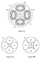
- FIG. 3 is a cross-sectional view of Y coils 54a, 54b and X coils 56a, 56b (within housing 46). All four coils are elliptical so that they impinge as little as possible on the space interior to the coils (in which the fibre 42 and magnet 48 must move) while maintaining the desired number of windings. The resulting ellipses each occupy one third of the housing diameter, leaving one third for the magnet 48 when in motion.
- FIG. 4A depicts four circular coils 60 within a housing 62 (shown in cross-section), with a shaded interior space 64 left vacant for the fibre and magnet; such coils could be employed in scanner 40.
- Figure 4B depicts the preferred arrangement of this embodiment, with four elliptical coils 66; shaded interior space 68 for the motion of the fibre and magnet is approximately twice the width and height of the space 64 of figure 4A .
- the additional internal space allows either a larger magnet or greater beam deflection - or both - than would be possible with circular coils.
- Housing 46 - and hence scanner 40 - has a final overall diameter of ⁇ 4.5 mm and length of ⁇ 30 mm. Indeed, a scanner according to this embodiment with a diameter of 3.5 mm has been constructed. In addition, a version with a diameter of 3.0 mm and a length of 23 mm has been designed, and it is envisaged that still smaller versions could readily be constructed.
- Figure 2B is a cross sectional side view of the scanner 40 at full Y deflection, that is, with fibre 42 deflected to its maximum extent in the Y direction.
- Scanner 40 is arranged to resonate at the first overtone in the X direction, however, as is illustrated schematically in figure 2C .
- a practical frequency range for mechanical resonant scanning is around 800 to 1000 Hz (or in some cases up to 1600 Hz) so, as mentioned above, scanner 40 is adapted to resonate at a first overtone of around 850 Hz.
- the permanent magnet 48 is located close to the antinode for this mode, so the magnet does not move far (despite a greater tip deflection in the x direction than in the y direction) and, when moving, is not rotated relative to its rest alignment by as great an angle as is apparent in the Y scan shown in figure 2B .
- the position of permanent magnet 48 along the fibre 42 is selected, in coarse terms, to provide sufficient scanning amplitude in the y direction (as the closer magnet 48 is to mount 44, the greater will be the scanning amplitude in the y direction), while providing adequate clearance in the x direction. This is then adjusted for optimum 1st overtone performance, and checked for compatibility with the requirement for low frequency alternating current Y deflection.
- the fundamental and first overtone frequencies have been computed and are plotted in figure 5 (as functions of the distance of the magnet 48 from the mount 44).
- the fundamental frequency 70 monotonically decreases as the distance of the magnet 48 from the mount 44.
- the overtone frequency 72 has a minimum at approximately 4 mm, which is in fact close to the position selected to provide a suitable Y deflection using a first overtone frequency of about 850 Hz. This position may be described as "optimum" in the sense that it employs the shortest fibre for this desired frequency, so minimizes the overall length of the scanner.
- the magnet For a small diameter scanner (such as a long rigid scanner made to fit down a small diameter tube), where diameter is the over-riding consideration, the magnet would be positioned at the antinode to get parallel magnet motion and best clearance.
- the aforementioned minimum frequency condition may be the preferred criterion, to provide the shortest scanner length for a given frequency of (overtone) operation.
- the magnet can be positioned between these two ideal positions; both are defined by parabolic minima so there would be very little sacrifice of performance.
- magnet 48 is located at the minimum shown in figure 5 , thus minimizing the length of the scanner, but this also places magnet 48 essentially at the vibration antinode so scanner diameter can also be minimized.
- Figure 6 illustrates a sine/sawtooth pattern 80, as employed with scanner 40.
- Figure 6 is a cross sectional view through housing 62 at the position of the tip 82 of fibre 42.
- the tip 82 is shown in its four extreme deflections, with the tip 82 as close as possible to the housing 62 in each case to provide the largest possible image.
- the central part 84 shown with a solid curve
- the scanner 40 uses almost the entire vertical or y direction scan (which comprises essentially a linear sawtooth motion), amounting in practice to approximately half the x direction travel of the tip 82. This maintains an approximately square image.
- a greater portion of the x direction deflection may be used, if a greater degree of image distortion is acceptable or post- imaging processing is used to reduce that distortion.
- Another possible scan pattern for use with scanner 40 comprises a variable ellipse where the fibre touches the tube at only two points (i.e. the ends of the ellipse).
- the area suitable for imaging when such a variable ellipse is used is slightly larger than with the pattern shown in figure 6 .
- the Y amplitude of the elliptical pattern can be increased compared with that shown in figure 1D , but the mapping to a display then becomes more difficult; for some applications, however, those scan limits would be acceptable even with direct conversion to a rectilinear display.
- a potential problem of scanner 40 - as it comprises a bimotional resonant cantilever - is that of whirling.
- Mount 44 is designed to provide a compliance that differs in the x and y directions; essentially straight line scanning can then be obtained with magnet 48 acted on by a single driving coil.
- Figure 7 is a schematic view of mount 44 (viewed along the z axis).
- Mount 44 includes a circular frame 90 with a thin transverse beam 92 that supports the base of the fibre 42.
- the transverse beam 92 can more readily twist to permit deflection in the y direction than it can warp to permit deflection in the x direction, so - as discussed above - compliance which is significantly different in the x and y directions.
- a thin polymer strip (of, say, 0.1 mm thickness and 1 mm width) could be attached laterally to the fibre 42 in front of a substantially rigid mount. This would also provide significantly different compliance in the x and y directions.
- the compliance is sufficiently different if the difference - expressed in terms of frequency difference - is about 20 Hz (provided that the permanent magnet 48, when scanning in the x direction, does not come too close to the pole pieces of the Y coils 54a, 54b. As a low frequency alternating current Y drive is employed, this frequency difference can be made quite large without endangering the operation of scanner 40 in the y direction.
- the X electronics of scanner 40 control the resonant scanning in the x direction, by sensing the x position of the magnet 48, controlling deflection at the overtone (with a positive feedback loop), suppressing vibration at the fundamental (with a negative feedback loop), and provides image synchronisation.
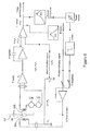
- Figure 8 is a circuit diagram of the X electronics, which also depicts fibre 42 and magnet 48 between X drive coil 56a and X sensor coil 56b.
- magnet 48 moves between the X coils, an emf is induced in X sensor coil 56b that is proportional to magnet velocity (rather than position), owing to magnet's motion relative to X sensor coil 56b.
- magnet velocity also be significant direct induction from the magnetic field of the X drive coil 56a into the X sensor coil 56b. More precisely, the mutual inductance will result in a signal proportional to the derivative of the drive current. It is easily measured off resonance and can be quantified.
- a high pass filter in the positive feedback loop selects the overtone from the X sense signal (at the top right of the circuit diagram). Otherwise the fibre could start up at the fundamental at about 200 Hz.
- the signal path continues through the overtone select filter, via an all-pass phase shifter to a limiter.
- This limiter provides the non-linearity (needed in a positive feedback oscillator) to control amplitude. Above a certain fibre deflection amplitude, the limiter produces a signal limited to the supply rails. This constant amplitude signal is then attenuated appropriately at the input to the drive stage to give the desired scan.
- the drive waveform is therefore not strictly sinusoid but rather square owing to the limiter, which assists in adjusting the X sense signal to be free of contamination from the drive signal. If the drive signal were a sine wave the contamination would be less obvious. With a square wave drive, the compensation can be adjusted to eliminate the square wave addition to the X sense using an oscilloscope.
- the negative feedback loop used for vibration damping contrast sharply with the positive loop described above. For example, it aims to provide maximum possible loop gain, provide linearity, and emphasise the lower frequency region (particularly the fundamental mechanical resonance), without disturbing the oscillating loop but while maintaining a phase margin over the entire frequency range.
- the intended negative loop could easily turn positive outside the frequency range of interest.
- a peaked low pass filter selects the fundamental frequency range in a negative loop that has direct access to the drive stage, effectively bypassing the limiter used for amplitude control of the overtone.
- the loop gain can be adjusted for best results in terms of the interference to the image from external vibration.
- the loop gain can be quantified by inserting a low amplitude probe signal into the drive stage and observing the signal returned at the filter output, which has passed through the entire system of X coils 56a, 56b and fibre 42. As the probe signal is tuned through the resonance band, amplitude and phase is measured relative to the probe. If the phase difference is close to 180° at peak response, the loop can be safely closed and vibration damping can be demonstrated.
- scanner 40 separately provides synchronising for image creation independent of excitation or return light being emitted by, or reflected back into, the fibre 42.
- image creation independent of excitation or return light being emitted by, or reflected back into, the fibre 42.
- all required information can be picked up from the target, but for reliable endoscope imaging it is necessary to know the location of the tip of fibre 42 so that an image can be generated.
- a virtue of confocal microscopy is that out-of-focus light is not admitted to the image. Operators often find that, on starting up a confocal microscope, the entire field of view is dark because the focal surface does not happen to intersect the object under view. Only as the depth is scanned (in the z direction) does any image information appear. For these reasons image-independent synchronising is essential for confocal microscopy.
- the X sense signal is processed for zero crossing (centre of display) and the imaging equipment can display the scanned signal using appropriate delay.
- this X synchronising signal initiates the whole computer loop that provides the Y scan signal back to the scanner 40.
- Figure 9 is a circuit diagram of the Y electronics of scanner 40, which control the Y drive to move the fibre 42 and magnet 48 in the y direction. Both Y coils 54a, 54b carry drive current, for reasons of symmetry and to obtain adequate deflection of the magnet.
- the force in the y direction acting on the magnet 48 has x components that are balanced. With only one Y coil in action, x would be modulated as the y scan proceeded, and at the extremes - where the magnet 48 approaches the poles of the Y coils - there would be the danger of the scan becoming elliptical. In addition, deflection in the y direction would not be as linear in terms of Y current.
- the Y drive signal enters the Y electronics (from imaging equipment) at the upper left of figure 9 ; this signal is typically derived from a digital to analogue converter, and it is important to remove any components near the fundamental frequency. These can come from both the conversion and any sharp flyback of the sawtooth. Both are attenuated by a filter designed for a time domain response with no overshoot or ringing even for instantaneous retrace.
- a bridge is provided (to the left of the Y coils in the figure), which is used to cancel the drive signal and extract the voltage induced in both coils by magnet vibration in the y direction.
- the bridge output is amplified and passed through a bandpass filter, and added to the Y drive to quench the fundamental resonance in the Y direction.
- the large moment required for the tine of a tuning fork scanner can only be provided by a balancing, preferably thicker, tine.
- a balancing, preferably thicker, tine By eliminating the fork entirely, the bending moment is reduced by an order of magnitude for a given deflection, as is the drive force also, and most importantly, the mechanical Q.
- the scanner 40 is thus less sensitive to mounting factors.
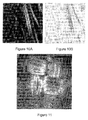
- Figure 10A is an image (reproduced in negative in figure 10B for clarity) of fluorescent fibres collected with the first of these scanners, and shows the effect of interference from vibration at the fundamental mechanical resonance. Although it appears as jitter in the x direction, it comes from very small glitches in the Y drive waveform. Similar effects could be produced with rapid retrace in the absence of careful filtering of the Y drive.
- Figure 11 is an image of woven fibres collected with the second scanner, in which the jitter is absent in both X or Y directions and individual fibres can be seen showing fine detail.
- Figure 12 is an image of a demanding target comprising a fluorescent grid at 12.5 micron spacing, and collected with the same scanner used to collect the image of figure 11 . This gives an indication of the field of view and linearity that can be achieved. The image has an approximately uniform scale over the entire field of view.
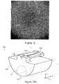
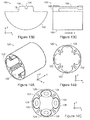
- FIGS 13A , 13B and 13C are views of an alternative fibre mount 100 (viz. alternative to mount 44), according to an embodiment of the present invention, for use with the scanner 40 of figure 2A .
- Fibre mount 100 - of wire cut titanium - comprises a generally semi-cylindrical base 102 (for locating in cylindrical housing 46 of scanner 40) and an integral forwardly directed cantilever 104 for holding an optical fibre 42, and joined to base 102 by neck 106.
- Base 102 has a diameter of approximately 3 mm.
- Cantilever 104 includes a upper groove 108 for receiving a portion of fibre 42, which then projects forwardly (i.e. in z direction) beyond cantilever 104 so that its forward end can be scanned essentially as illustrated in figures 2A to 2C .
- Base 102 is formed as less than a complete semi-cylinder to thereby locate groove 108 such that fibre 42 is coaxial with cylindrical housing 46. Fibre 42 is held in groove 108 with an adhesive. Groove 108 is longer (in the z direction) than the thickness (in the z direction) of mount 44, so fibre 42 can be more securely located in fibre mount 100 of this embodiment than in mount 44.
- cantilever 104 acts somewhat like a springboard as it has a width in the lateral or x direction (of approximately 1 mm) that is significantly greater than its thickness in the vertical or y direction; it is thus stiffer and hence more resistant to displacement in the x direction than in the y direction.
- the resonance frequency for vibration of fibre 42 in the x direction was found to be 46 kHz greater than the resonance frequency for vibration of fibre 42 in the y direction, thereby facilitating a fast X scan and a slow Y scan.
- Fibre mount 100 may optically include a generally cylindrical cut-out 112 in its lower periphery 114, to lighten mount 100 or to provide a feed-through to the forward portion of scanner 40 for electrical cables or the like.
- Figures 14A, 14B and 14C are views of an alternative coil holder 120, according to an embodiment of the present invention, for use with the scanner 40 of figure 2A .
- Figure 14C depicts coil holder 120 provided with coils.
- Coil holder 120 - also of wire cut titanium - is generally cylindrical with a diameter of approximately 3 mm, and includes four identical and evenly spaced elliptical internal recesses 122 for accommodating four elliptical electromagnetic coils (shown at 124 in figure 14C ) comparable to coils 50 of scanner 40.
- coils 124 are held by their outer windings rather than by their cores 126, through the engagement of their outer windings and the surfaces of respective recesses 122.
- coils 124 do not abut the interior wall of cylindrical housing 46, but rather abut the surfaces of recesses 122.
- Coil holder 120 allows precise and quick positioning of coils 124, and is inexpensive to manufacture.
- one or more slots or grooves may optionally be provided in the external surface of coil holder 120 for engaging corresponding flanges provided on interior wall 52 of housing 46. These optional grooves and flanges would facilitate the positioning and securing in position of coil holder 120.
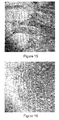
- Figure 15 is an image of small intestine villi from a mouse, obtained with a confocal endoscope comprising an optical fibre scanner according to the embodiment of figure 2A though employing fibre mount 100 of figures 13A to 13C and coil holder 120 of figures 14A and 14B .
- the mouse was intravenously injected with 0.5 mL of a 1% solution of sodium fluorescein, and topical acriflavine (0.05% solution) was applied to the villi; the tissue was then imaged using 488 nm laser illumination.
- Figure 16 is an image of liver vessels from a mouse, collected with the same apparatus as was the image of figure 15 .
- the sample was prepared in the same manner as was that imaged in figure 15 (though without the application of topical acriflavine).
- the field of view is approximately 500 ⁇ m ⁇ 500 ⁇ m for the images of both figures 15 and 16 .
Abstract
Description
- This application is based on and claims the benefit of the filing date of
US application no. 60/825,597 filed 14 September 2006 - The present invention relates to a method and apparatus for providing scanning with a light transmitter (such as an optical fibre), of particular but by no means exclusive application in microscopy, endoscopy (including endomicroscopy), and confocal microscopy and endoscopy.
- Some existing microscopes and endoscopes employ one or more optical fibre for light delivery to a sample and light collection from the sample. To image the sample, the delivered light is scanned across the sample; by scanning the exit tip of the fibre, this can been done by scanning the light after its emission by the fibre, or by providing multiple return fibres and collecting light sequentially from each.
- The scanning of the fibre can be effected by attaching the exit tip of the fibre to a mechanical actuator, such as a vibrating tine of a tuning fork. Alternatively, one existing approach employs an actuator located at the base of a fibre, to impart a scanning motion to the fibre and hence its tip.
- For example, four background
art scanning mechanisms figures 1A to 1D respectively.Scanning mechanisms figures 1A and 1B each include anasymmetric fork 18 of ferromagnetic material to carry an optical fibre (not shown). A first (scanning) tine offork 18 is axially located and a fixedX drive coil 20 surrounds both scanning tine and the second (balancing) tine. A Y scan is obtained by a see-saw action whereby thefork 18 rocks inside theX coil 20. The driving force for the Y scan is obtained with apermanent magnet 22 and anelectromagnet 24 that carries a Y drive current. Inscanning mechanism 12 offigure 1B , the magnetic circuit is folded to reduce overall length, and theY coil 24 is hollow. - Synchronisation in both
scanning mechanisms fork 18, which is used to drive the fork at resonance through an amplifier. The X scan in both mechanisms is sinusoidal, and usually the central half of the mechanical scan is used for imaging. The outer scan region, where the fibre tip slows down and reverses, is discarded. -
Scanning mechanism 14 offigure 1C is the base excited cantilever using a tube piezo driver. This layout is seen in scanning microscopes, bar-code scanners, and a spiral scanning endoscope developed at the University of Washington. Such systems appear, however, to suffer from problems in the control of scan distortion. - Referring to
figure 1D , scanning mechanism 16 - disclosed inWO 04/40267 magnet 26 attached to afibre 28 near thebase 30 of the fibre, such that the fibre acts as a vibrating cantilever. Themagnet 26 is activated and controlled by four electromagnets orcoils 32 that surround the magnet. - Examples of some of these scanning systems are disclosed in
US Patent No. 6,294,775 ,US Patent No. 6,975,898 andUS Patent No. 6,845,190 . - According to a first broad aspect, therefore, the invention provides a method of scanning a light transmitter having an exit tip, comprising:
- supporting the light transmitter in a mount located remotely from the exit tip;
- applying a driving force to the light transmitter between the mount and the exit tip;
- driving the light transmitter to vibrate resonantly in a first direction with a first driving force and to vibrate non-resonantly in a second direction orthogonal to the first direction with a second driving force; and
- synchronizing vibration of the light transmitter in the first direction with vibration of the light transmitter in the second direction so that the exit tip of the light transmitter executes a scan pattern.
- The scan pattern may approximate a rectilinear raster scan, with the light transmitter executing sinusoidal vibration in the first direction and linear vibration in the second direction.
- In one particular embodiment, the method includes vibrating the light transmitter in the first direction at the first overtone (also referred to as the second order of vibration) of mechanical resonance.
- The method may include:
- driving the light transmitter with an axially polarised magnet mounted on the light transmitter (such as near the mount), a first pair of axially oriented electromagnetic coils located on either side of the magnet in the first direction comprising a drive coil for driving the magnet in the first direction and a sensor coil for providing a signal for use in generating a position signal indicative of the position of the magnet in the first direction, and a second pair of axially oriented electromagnetic coils located on either side of the magnet in the second direction for driving the magnet in the second direction; and
- using the position signal to provide positive feedback to maintain light transmitter vibration in the first direction (and optionally for synchronising an image display).
- In one embodiment, the method includes deriving the position signal by integrating the output signal of the sensor coil.
- In a particular embodiment, the method may include subtracting a signal proportional to the drive current from the position signal to compensate for contamination of the position signal by a current induced in the sensor coil by the magnetic field of the drive coil.
- In these embodiments, the magnet may be tapered in the second direction to maximize the volume of the magnet that can be accommodated between the second first pair of electromagnetic coils (owing to the rotation of the magnet as it is scanned in that direction). However, the magnet may be less tapered or untapered in the first direction (owing to the almost parallel motion of the magnet in the first direction when position at or near the antinode).
- In other embodiments, additional coils may be employed for driving the light transmitter in the first direction, the second direction, or in both the first direction and second directions.
- In one embodiment, the method includes locating the magnet substantially at a vibration antinode so that the magnet moves laterally without significant rotation, or substantially at a minimum in the overtone frequency versus magnet position curve to minimize required light transmitter length. In another embodiment, the method includes locating the magnet substantially at both a vibration antinode and a minimum in the overtone frequency versus magnet position curve.
- For such magnet locations the resultant fundamental resonant frequency may be too low for the desired frequencies (such as require in some scanners), so it becomes desirable to employ an overtone resonance (e.g. the first overtone), such as at around four times the frequency.
- The method may include vibrating the light transmitter in the second direction non-resonantly with low frequency alternating current excitation of the second pair of coils.
- That is, the magnetic force available in some compact scanners may be limited, so the magnet may in some embodiments be removed from the mounting point of the light transmitter (or base) to obtain sufficient bending moment for tip desired deflection (particularly if driven in that direction with low frequency alternating current excitation and non-resonant operation).
- In an alternative embodiment, the method includes vibrating the light transmitter in the second direction non-resonantly with varying direct current excitation of the second pair of coils. In such an embodiment, the method may include providing a restorative force (for restoring the light transmitter) with a spring or with the resilience of the light transmitter.
- The light transmitter typically comprises an optical fibre, which may be single moded but need not be, according to application. Alternatively it may comprise a plurality of fibres or a fibre bundle, where each fibre may be single moded or otherwise.
- The method may include providing negative feedback at the fundamental frequency in both first and second directions.
- This would be done because a low fundamental resonance frequency creates a susceptibility to external vibrations, and any signals around this frequency in a linear drive.
- The method may include mounting the light transmitter to have compliance in the first direction that is significantly different from compliance in the second direction.
- The method may include mounting the light transmitter on a thin transverse beam. The predominantly torsional strain of this beam provides the additional compliance to lower the resonant frequency in one direction.
- In another embodiment, the method includes mounting the light transmitter on a cantilever with a lower resonant frequency in one (e.g. y) direction than in the other (e.g. x) direction.
- According to a second broad aspect, the invention provides a scanning apparatus, comprising:
- a light transmitter having an exit tip;
- a mount for supporting the light transmitter located remotely from the exit tip;
- a drive for driving the light transmitter to vibrate resonantly in a first direction with a first driving force and to vibrate non-resonantly in a second direction orthogonal to the first direction with a second driving force; and
- a synchronizer for synchronizing vibration of the light transmitter in the first direction with vibration of the light transmitter in the second vibration so that the exit tip of the light transmitter executes a scan pattern;
- wherein the drive applies a driving force to the light transmitter between the mount and the exit tip.
- The apparatus may include a drive comprising:
- an axially polarised magnet mounted on the light transmitter (such as near the mount);
- a first pair of axially oriented electromagnetic coils located on either side of the magnet in the first direction comprising a drive coil for driving the magnet in the first direction and a sensor coil for providing a signal for use in generating a position signal indicative of the position of the magnet in the first direction; and
- a second pair of axially oriented electromagnetic coils located on either side of the magnet in the second direction for driving the magnet in the second direction;
- wherein the position signal is suitable for providing feedback to maintain light transmitter vibration in the first direction (and optionally for synchronising an image display).
- In one embodiment, the apparatus includes an integrator for integrating the output signal of the sensor coil to generate the position signal.
- In a particular embodiment, the apparatus is configured to subtract a signal proportional to the drive current from the position signal to compensate for contamination of the position signal by a current induced in the sensor coil by the magnetic field of the drive coil.
- In these embodiments, the magnet may be tapered in the second direction to maximize the volume of the magnet that can be accommodated between the second first pair of electromagnetic coils. However, the magnet may be less tapered or untapered in the first direction.
- In one embodiment, the magnet is located substantially at a vibration antinode so that the magnet moves laterally without significant rotation, or substantially at a minimum in the overtone frequency versus magnet position curve, or substantially at both a vibration antinode and a minimum in the overtone frequency versus magnet position curve.
- The apparatus may be configured to vibrate the light transmitter in the second direction non-resonantly with low frequency alternating current excitation of the second pair of coils.
- In other embodiments, the apparatus includes a source of varying direct current for exciting the second pair of coils and thereby vibrate the light transmitter in the second direction non-resonantly. In such embodiments, a restorative force may be provided by the resilience of the light transmitter, or the apparatus may include a spring or other resilient mechanism for providing a restorative force.
- The light transmitter typically comprises an optical fibre. Alternatively it may comprise a plurality of fibres or a fibre bundle.
- The mount for the light transmitter (such as a thin transverse beam or a cantilever) may have significantly different compliances in said first and second directions.
- The apparatus may include an imaging system for processing return light from the light transmitter and displaying an image generated therefrom.
- The invention also provides an imaging apparatus comprising a scanning apparatus as described above, such as a microscope, an endoscope, an endomicroscope or an optical coherence tomograph.
- In some embodiments the imaging apparatus is a confocal imaging apparatus, such as a confocal microscope or a confocal endoscope or a multiphoton endoscope.
- In order that the invention may be more clearly ascertained, embodiments will now be described, by way of example, with reference to the accompanying drawing, in which:
-
Figures 1A to 1D are schematic views of background art scanning mechanisms; -
Figure 2A is a schematic side view of a scanner according to a first embodiment of the present invention; -
Figure 2B is a schematic side view of the scanner offigure 2A in use; -
Figure 2C is another schematic side view of the scanner offigure 2A in use; -
Figure 3 is a cross-sectional schematic view of the coils of the scanner offigure 2A ; -
Figures 4A and 4B are schematic views illustrating the benefit of elliptical coils in the scanner offigure 2A compared to circular coils; -
Figure 5 are plots of the fundamental and first overtone frequencies for a total fibre length of 18 mm as functions of the distance of the magnet from the mount of the scanner offigure 2A ; -
Figure 6 illustrates an example of a sine/sawtooth scan pattern employed by the scanner offigure 2A ; -
Figure 7 is a schematic view of the mount of the scanner offigure 2A ; -
Figure 8 is a circuit diagram of the X electronics of the scanner offigure 2A ; -
Figure 9 is a circuit diagram of the Y electronics of the scanner offigure 2A ; -
Figure 10A is an exemplary image of fluorescent fibres collected with an endoscope including a scanner constructed according to an embodiment of the present invention; -
Figure 10B is a negative version of the image offigure 10A , provided for clarity; -
Figure 11 is an exemplary image of woven fibres collected with an endoscope including another scanner constructed according to an embodiment of the present invention; -
Figure 12 is an exemplary image of a fluorescent grid collected with the endoscope used to collect the image offigure 11 ; -
Figures 13A ,13B and 13C are views of an alternative fibre mount according to an embodiment of the present invention for use with the scanner offigure 2A ; -
Figures 14A, 14B and 14C are views of an alternative coil holder according to an embodiment of the present invention for use with the scanner offigure 2A ; -
Figure 15 is an image of small intestine villi from a mouse obtained with the scanner offigure 2A employing the fibre mount offigures 13A to 13C and the coil holder offigures 14A, 14B and 14C ; and -
Figure 16 is an image of liver vessels from a mouse obtained with the scanner offigure 2A employing the fibre mount offigures 13A to 13C and the coil holder offigures 14A, 14B and 14C . - A scanner according to a first embodiment of the present invention is shown schematically at 40 in
figure 2A , which is a cross sectional side view of the scanner.Scanner 40 is adapted for use as the scanning mechanism of an endoscope, and includes a flexible optical transmitter in the form of a standardoptical fibre 42 mounted in amount 44 and surrounded by a generallycylindrical housing 46. It should be noted that the flexible optical transmitter may alternatively be in the form of a fibre bundle, but in the following description, for simplicity, it will be referred to as "fibre 42" rather than as "fibre orfibres 42", though it should be understood that the latter may be appropriate in some embodiments. - The
scanner 40 also includes apermanent magnet 48 mounted onfibre 42, at approximately a quarter of the length of the fibre frommount 44. The precise location ofmagnet 48 is discussed in detail below. The magnet can be mounted in any suitable way, including by locating the fibre in an aperture through the magnet or in a slot in one lateral face of the magnet; the magnet will typically be held in place with glue. In thisembodiment magnet 48 has a slot (not shown) in its upper face, in which the fibre is located and held by glue. - The length of
fibre 42 frommount 44 tomagnet 48 is about 4 mm, and from mount tofibre tip 18 mm; thefibre 42 has a diameter of approximately 125 micron. The length ofmagnet 48 is about 2 mm. This geometry is suitable in view of the stiffness of a standard fibre of these dimensions. The distance ofmagnet 48 frommount 44 is greater than might be expected, but is employed to obtain the desired Y deflection without the benefit of mechanical Q. As a result the fundamental resonance frequency (of about 200 Hz) is relatively low and may not be suitable for imaging in some applications. This frequency also leads to sensitivity to unwelcome interference due to ringing in response to external vibrations. In addition, a fast Y retrace can induce long term ringing which carries over into a displayed image. The direct relationship between gravitational deflection and resonance frequency is discussed in more detail below. - The
scanner 40 includes a drive in the form of fourelectromagnetic coils 50 located aroundmagnet 48 spaced equally from each other, insideinterior wall 52 ofhousing 46. The four coils comprise twoY coils e.g. core 55a ofcoil 54a); each core has an elliptical cross section of ∼0.8 mm major axis and ∼0.4 mm minor axis, and in one particular embodiment a 0.7 mm major axis and a 0.3 mm minor axis. The coils abut the interior wall ofcylindrical housing 46, and are supported by their cores; the cores are in turn attached to and supported by a frame (not shown) - to which thefibre mount 44 is also attached - around which thehousing 46 is fitted. - As is explained in greater detail below, the
fibre 42 is driven resonantly in the x direction (the 'fast scan') with an operating frequency of about 850 Hz, using the first overtone (automatically selected by the electronics). The orthogonal (i.e. y) direction is scanned in a non-resonant manner using a low frequency alternating current drive. - Though discussed in greater detail below, briefly, overtone operation in the x direction is obtained by using one X coil (referred to as the X drive coil) to produce the driving force, and the other X coil as a sensor (the X sensor coil). The emf induced in the X sensor coil is approximately proportional to the magnet velocity, and this induced voltage is electronically integrated to provide feedback information. There is also a directly induced voltage from the X drive coil. This is cancelled by sampling the drive current and subtracting a balancing proportion from the integrated waveform.
- The signal proportional to the movement of the
magnet 48 is used both for positive feedback after phase shifting to keep thefibre 42 vibrating, and also for synchronising an image display if - as would be usual - the output ofscanner 40 is ultimately coupled to such a display. A frequency selective filter is included in the feedback path to prevent oscillation at the fundamental frequency of the cantilever. This arrangement is self-starting at the required overtone. - Y coils 54a, 54b provide vibration in the y direction; they provide balance and the required greater force needed for non-resonant scanning. The symmetry also reduces any direct induction into the X sensor coil, and the resonant drive signal into
Y coils - Sensing of unwanted vibration at the fundamental in the y direction is accomplished with a bridge circuit. The emf induced by movement of the
magnet 48 is separated and electronically enhanced by a frequency selective filter and used in a negative feedback loop. A monitor signal is also provided so that any mechanical disturbance can be detected, even while the scanner is in operation. - It should be noted that
magnet 48 is generally trapezoidal in shape both in the plane depicted infigure 2A and - to a lesser degree - in the plane perpendicular thereto, such that it tapers away frommount 44. This maximizes the angle through which fibre 42 (and hence magnet 48) can be deflected - from the equilibrium position shown in this figure - both in the plane of the figure and in the plane perpendicular to that plane, as constrained by avoiding contact with the coils and maximizing the volume of the magnet. - Thus, the motion of the magnet is maximized for the space provided, which is important for use in a small diameter endoscope. Similarly, the
coils 50 are designed to minimize their volume for their desired strength.Figure 3 is a cross-sectional view ofY coils X coils fibre 42 andmagnet 48 must move) while maintaining the desired number of windings. The resulting ellipses each occupy one third of the housing diameter, leaving one third for themagnet 48 when in motion. - At maximum size the coils touch the
housing 46 with equal curvature, and touch each other. The deflection of the magnet is calculated from elastic beam theory and the desired (or required) fibre tip deflection. The maximum magnet cross section that can be accommodated can then be determined. The benefit of using elliptical rather than circular coils is evident fromfigures 4A and 4B. Figure 4A depicts fourcircular coils 60 within a housing 62 (shown in cross-section), with a shadedinterior space 64 left vacant for the fibre and magnet; such coils could be employed inscanner 40.Figure 4B , however, depicts the preferred arrangement of this embodiment, with fourelliptical coils 66; shadedinterior space 68 for the motion of the fibre and magnet is approximately twice the width and height of thespace 64 offigure 4A . The additional internal space allows either a larger magnet or greater beam deflection - or both - than would be possible with circular coils. - Housing 46 - and hence scanner 40 - has a final overall diameter of ∼4.5 mm and length of ∼30 mm. Indeed, a scanner according to this embodiment with a diameter of 3.5 mm has been constructed. In addition, a version with a diameter of 3.0 mm and a length of 23 mm has been designed, and it is envisaged that still smaller versions could readily be constructed.
-
Figure 2B is a cross sectional side view of thescanner 40 at full Y deflection, that is, withfibre 42 deflected to its maximum extent in the Y direction.Scanner 40 is arranged to resonate at the first overtone in the X direction, however, as is illustrated schematically infigure 2C . A practical frequency range for mechanical resonant scanning is around 800 to 1000 Hz (or in some cases up to 1600 Hz) so, as mentioned above,scanner 40 is adapted to resonate at a first overtone of around 850 Hz. Thepermanent magnet 48 is located close to the antinode for this mode, so the magnet does not move far (despite a greater tip deflection in the x direction than in the y direction) and, when moving, is not rotated relative to its rest alignment by as great an angle as is apparent in the Y scan shown infigure 2B . This has two consequences: little if any taper need be applied to themagnet 48 in the magnet's cross section that is apparent infigure 2C , and the size of that cross section can be maximized to take advantage to this minimal deflection. - The position of
permanent magnet 48 along thefibre 42 is selected, in coarse terms, to provide sufficient scanning amplitude in the y direction (as thecloser magnet 48 is to mount 44, the greater will be the scanning amplitude in the y direction), while providing adequate clearance in the x direction. This is then adjusted for optimum 1st overtone performance, and checked for compatibility with the requirement for low frequency alternating current Y deflection. - For a total fibre length of 18 mm the fundamental and first overtone frequencies have been computed and are plotted in
figure 5 (as functions of the distance of themagnet 48 from the mount 44). Thefundamental frequency 70 monotonically decreases as the distance of themagnet 48 from themount 44. However, theovertone frequency 72 has a minimum at approximately 4 mm, which is in fact close to the position selected to provide a suitable Y deflection using a first overtone frequency of about 850 Hz. This position may be described as "optimum" in the sense that it employs the shortest fibre for this desired frequency, so minimizes the overall length of the scanner. - For a small diameter scanner (such as a long rigid scanner made to fit down a small diameter tube), where diameter is the over-riding consideration, the magnet would be positioned at the antinode to get parallel magnet motion and best clearance. However, if the scanner is for use in the rigid tip of a flexible endoscope (which are typically more useful if the rigid tip length is short), the aforementioned minimum frequency condition may be the preferred criterion, to provide the shortest scanner length for a given frequency of (overtone) operation. With practical clearances the magnet can be positioned between these two ideal positions; both are defined by parabolic minima so there would be very little sacrifice of performance. In this embodiment,
magnet 48 is located at the minimum shown infigure 5 , thus minimizing the length of the scanner, but this also placesmagnet 48 essentially at the vibration antinode so scanner diameter can also be minimized. -
Figure 6 illustrates a sine/sawtooth pattern 80, as employed withscanner 40.Figure 6 is a cross sectional view throughhousing 62 at the position of thetip 82 offibre 42. Thetip 82 is shown in its four extreme deflections, with thetip 82 as close as possible to thehousing 62 in each case to provide the largest possible image. Generally, only the central part 84 (shown with a solid curve) of the x direction sinusoidal deflection 80 - and withtip 82 moving in one direction (such as left to right) - is used for data collection. However, thescanner 40 uses almost the entire vertical or y direction scan (which comprises essentially a linear sawtooth motion), amounting in practice to approximately half the x direction travel of thetip 82. This maintains an approximately square image. A greater portion of the x direction deflection may be used, if a greater degree of image distortion is acceptable or post- imaging processing is used to reduce that distortion. - Other scan patterns have been developed for those cases where the bimotional fibre cannot be sufficiently deflected except at resonance and advantage is taken of mechanical Q. This occurs when the available driving force is too small to deflect the fibre directly at low frequency when driven with an alternating current drive.
- Another possible scan pattern for use with
scanner 40 comprises a variable ellipse where the fibre touches the tube at only two points (i.e. the ends of the ellipse). In terms of speed, the area suitable for imaging when such a variable ellipse is used is slightly larger than with the pattern shown infigure 6 . The Y amplitude of the elliptical pattern can be increased compared with that shown infigure 1D , but the mapping to a display then becomes more difficult; for some applications, however, those scan limits would be acceptable even with direct conversion to a rectilinear display. - A potential problem of scanner 40 - as it comprises a bimotional resonant cantilever - is that of whirling.
Mount 44 is designed to provide a compliance that differs in the x and y directions; essentially straight line scanning can then be obtained withmagnet 48 acted on by a single driving coil.Figure 7 is a schematic view of mount 44 (viewed along the z axis).Mount 44 includes acircular frame 90 with a thintransverse beam 92 that supports the base of thefibre 42. Thetransverse beam 92 can more readily twist to permit deflection in the y direction than it can warp to permit deflection in the x direction, so - as discussed above - compliance which is significantly different in the x and y directions. - Alternatively, a thin polymer strip (of, say, 0.1 mm thickness and 1 mm width) could be attached laterally to the
fibre 42 in front of a substantially rigid mount. This would also provide significantly different compliance in the x and y directions. - Whatever technique is employed, it is estimated that the compliance is sufficiently different if the difference - expressed in terms of frequency difference - is about 20 Hz (provided that the
permanent magnet 48, when scanning in the x direction, does not come too close to the pole pieces of the Y coils 54a, 54b. As a low frequency alternating current Y drive is employed, this frequency difference can be made quite large without endangering the operation ofscanner 40 in the y direction. - The X electronics of
scanner 40 control the resonant scanning in the x direction, by sensing the x position of themagnet 48, controlling deflection at the overtone (with a positive feedback loop), suppressing vibration at the fundamental (with a negative feedback loop), and provides image synchronisation. -
Figure 8 is a circuit diagram of the X electronics, which also depictsfibre 42 andmagnet 48 betweenX drive coil 56a andX sensor coil 56b. Asmagnet 48 moves between the X coils, an emf is induced inX sensor coil 56b that is proportional to magnet velocity (rather than position), owing to magnet's motion relative toX sensor coil 56b. There will also be significant direct induction from the magnetic field of theX drive coil 56a into theX sensor coil 56b. More precisely, the mutual inductance will result in a signal proportional to the derivative of the drive current. It is easily measured off resonance and can be quantified. - Both of these effects - the induced emf and the direct induction - are annotated in the figure as two voltage dx di generators (respectively


X drive coil 56a. Finally, at the top right of the circuit diagram a signal is produced that is a good indicator of magnet position. There is a slight asymmetry in the nominally sinusoidal wave that is due to the geometry of the magnetic field, but it is of little consequence. - A high pass filter in the positive feedback loop selects the overtone from the X sense signal (at the top right of the circuit diagram). Otherwise the fibre could start up at the fundamental at about 200 Hz. The signal path continues through the overtone select filter, via an all-pass phase shifter to a limiter. This limiter provides the non-linearity (needed in a positive feedback oscillator) to control amplitude. Above a certain fibre deflection amplitude, the limiter produces a signal limited to the supply rails. This constant amplitude signal is then attenuated appropriately at the input to the drive stage to give the desired scan. The drive waveform is therefore not strictly sinusoid but rather square owing to the limiter, which assists in adjusting the X sense signal to be free of contamination from the drive signal. If the drive signal were a sine wave the contamination would be less obvious. With a square wave drive, the compensation can be adjusted to eliminate the square wave addition to the X sense using an oscilloscope.
- The role of scan amplitude control can be readily understood if ones imagines switching the system on with that control initially set to zero. If the gain is gradually increased, oscillation will start, producing a low level sine wave when the loop gain is unity. At this point the amplitude rises and falls markedly with the slightest change in the gain control with very slight amplitude regulation occurring with the build up of wind resistance and other level dependent losses. Advancing the control further will increase the amplitude at the limiter input so that clipping of the upper and lower peaks of the sine wave starts. At sufficiently high amplitude, the waveform at the input to the drive stage will approach the square wave referred to above.
- Some of the characteristics of the negative feedback loop used for vibration damping contrast sharply with the positive loop described above. For example, it aims to provide maximum possible loop gain, provide linearity, and emphasise the lower frequency region (particularly the fundamental mechanical resonance), without disturbing the oscillating loop but while maintaining a phase margin over the entire frequency range. The intended negative loop could easily turn positive outside the frequency range of interest.
- It might be imagined that a single loop would suffice, with the phase characteristic adjusted over the two frequency ranges to act as a negative loop at low frequencies and a positive loop at high frequencies. However, the non-linearity needed for amplitude control would cause cross-modulation of the signals in the drive to the
X drive coil 56a. For that reason parallel loops are employed in this embodiment, which add after the limiter at the input to the drive stage. - Thus, commencing at the X sense signal, a peaked low pass filter selects the fundamental frequency range in a negative loop that has direct access to the drive stage, effectively bypassing the limiter used for amplitude control of the overtone. During scanning the loop gain can be adjusted for best results in terms of the interference to the image from external vibration. Alternatively the loop gain can be quantified by inserting a low amplitude probe signal into the drive stage and observing the signal returned at the filter output, which has passed through the entire system of
X coils fibre 42. As the probe signal is tuned through the resonance band, amplitude and phase is measured relative to the probe. If the phase difference is close to 180° at peak response, the loop can be safely closed and vibration damping can be demonstrated. - A distinction should be drawn between scanning versus imaging from a scan. Further,
scanner 40 separately provides synchronising for image creation independent of excitation or return light being emitted by, or reflected back into, thefibre 42. In applications such as bar code scanning all required information can be picked up from the target, but for reliable endoscope imaging it is necessary to know the location of the tip offibre 42 so that an image can be generated. - A virtue of confocal microscopy is that out-of-focus light is not admitted to the image. Operators often find that, on starting up a confocal microscope, the entire field of view is dark because the focal surface does not happen to intersect the object under view. Only as the depth is scanned (in the z direction) does any image information appear. For these reasons image-independent synchronising is essential for confocal microscopy.
- Thus, returning to the top right of
figure 8 , the X sense signal is processed for zero crossing (centre of display) and the imaging equipment can display the scanned signal using appropriate delay. - At the start-up of the
scanner 40 and its electronics, this X synchronising signal initiates the whole computer loop that provides the Y scan signal back to thescanner 40. -
Figure 9 is a circuit diagram of the Y electronics ofscanner 40, which control the Y drive to move thefibre 42 andmagnet 48 in the y direction. Both Y coils 54a, 54b carry drive current, for reasons of symmetry and to obtain adequate deflection of the magnet. - The force in the y direction acting on the
magnet 48 has x components that are balanced. With only one Y coil in action, x would be modulated as the y scan proceeded, and at the extremes - where themagnet 48 approaches the poles of the Y coils - there would be the danger of the scan becoming elliptical. In addition, deflection in the y direction would not be as linear in terms of Y current. - There is another symmetry condition related to induction of the X drive field into the Y coils 54a, 54b. The
X drive coil 56a is adjacent to, and almost in contact with, bothY coils figure 3 ). By connectingY coils figure 9 , the induction of X into Y is largely cancelled. - The Y drive signal enters the Y electronics (from imaging equipment) at the upper left of
figure 9 ; this signal is typically derived from a digital to analogue converter, and it is important to remove any components near the fundamental frequency. These can come from both the conversion and any sharp flyback of the sawtooth. Both are attenuated by a filter designed for a time domain response with no overshoot or ringing even for instantaneous retrace. - There remains the problem of ringing at the fundamental due to vibration in the external environment. Since there is no Y sense coil, the emf induced in the Y coils 54a, 54b by the movement of the
magnet 48 is used. This is done in the presence of the sawtooth drive in both Y coils. - A bridge is provided (to the left of the Y coils in the figure), which is used to cancel the drive signal and extract the voltage induced in both coils by magnet vibration in the y direction. The bridge output is amplified and passed through a bandpass filter, and added to the Y drive to quench the fundamental resonance in the Y direction.
- In addition to the potential perturbing effects discussed above, simple vibrational interference to the scan and the more subtle parametric modulation effect (where amplitude depends on mounting compliance) can present problems. The former arises from movement of the scanner during use (such as in an endoscope in vivo).
- One may consider how the bending moment for scanning is supplied at the base of the
cantilever fibre 42. The large moment required for the tine of a tuning fork scanner can only be provided by a balancing, preferably thicker, tine. By eliminating the fork entirely, the bending moment is reduced by an order of magnitude for a given deflection, as is the drive force also, and most importantly, the mechanical Q. Thescanner 40 is thus less sensitive to mounting factors. - An X-only fibre cantilever was tested with a light weight mounting. The X sense signal was then measured under a variety of mounting conditions with constant drive. The amplitude varied by only a few percent, except for one case where clamping with pliers some distance from the base seemed to resonate together with the assembly. Merely touching the fibre mount region made the effect disappear.
- Two scanners were then constructed, based on
scanner 40, and incorporated into an endoscope. Several images were taken with these two scanners.Figure 10A is an image (reproduced in negative infigure 10B for clarity) of fluorescent fibres collected with the first of these scanners, and shows the effect of interference from vibration at the fundamental mechanical resonance. Although it appears as jitter in the x direction, it comes from very small glitches in the Y drive waveform. Similar effects could be produced with rapid retrace in the absence of careful filtering of the Y drive. -
Figure 11 is an image of woven fibres collected with the second scanner, in which the jitter is absent in both X or Y directions and individual fibres can be seen showing fine detail. -
Figure 12 is an image of a demanding target comprising a fluorescent grid at 12.5 micron spacing, and collected with the same scanner used to collect the image offigure 11 . This gives an indication of the field of view and linearity that can be achieved. The image has an approximately uniform scale over the entire field of view. -
Figures 13A ,13B and 13C are views of an alternative fibre mount 100 (viz. alternative to mount 44), according to an embodiment of the present invention, for use with thescanner 40 offigure 2A . Fibre mount 100 - of wire cut titanium - comprises a generally semi-cylindrical base 102 (for locating incylindrical housing 46 of scanner 40) and an integral forwardly directedcantilever 104 for holding anoptical fibre 42, and joined to base 102 byneck 106.Base 102 has a diameter of approximately 3 mm.Cantilever 104 includes aupper groove 108 for receiving a portion offibre 42, which then projects forwardly (i.e. in z direction) beyondcantilever 104 so that its forward end can be scanned essentially as illustrated infigures 2A to 2C .Base 102 is formed as less than a complete semi-cylinder to thereby locategroove 108 such thatfibre 42 is coaxial withcylindrical housing 46.Fibre 42 is held ingroove 108 with an adhesive.Groove 108 is longer (in the z direction) than the thickness (in the z direction) ofmount 44, sofibre 42 can be more securely located infibre mount 100 of this embodiment than inmount 44. - In addition,
cantilever 104 acts somewhat like a springboard as it has a width in the lateral or x direction (of approximately 1 mm) that is significantly greater than its thickness in the vertical or y direction; it is thus stiffer and hence more resistant to displacement in the x direction than in the y direction. As a result, in an embodiment ofscanner 40 withfibre mount 100, the resonance frequency for vibration offibre 42 in the x direction was found to be 46 kHz greater than the resonance frequency for vibration offibre 42 in the y direction, thereby facilitating a fast X scan and a slow Y scan. -
Fibre mount 100 may optically include a generally cylindrical cut-out 112 in itslower periphery 114, to lightenmount 100 or to provide a feed-through to the forward portion ofscanner 40 for electrical cables or the like. -
Figures 14A, 14B and 14C are views of analternative coil holder 120, according to an embodiment of the present invention, for use with thescanner 40 offigure 2A .Figure 14C depictscoil holder 120 provided with coils. Coil holder 120 - also of wire cut titanium - is generally cylindrical with a diameter of approximately 3 mm, and includes four identical and evenly spaced ellipticalinternal recesses 122 for accommodating four elliptical electromagnetic coils (shown at 124 infigure 14C ) comparable tocoils 50 ofscanner 40. Unlikecoils 50 ofscanner 40, however, coils 124 are held by their outer windings rather than by theircores 126, through the engagement of their outer windings and the surfaces ofrespective recesses 122. Hence, coils 124 do not abut the interior wall ofcylindrical housing 46, but rather abut the surfaces ofrecesses 122.Coil holder 120 allows precise and quick positioning ofcoils 124, and is inexpensive to manufacture. - In addition, one or more slots or grooves (not shown) may optionally be provided in the external surface of
coil holder 120 for engaging corresponding flanges provided oninterior wall 52 ofhousing 46. These optional grooves and flanges would facilitate the positioning and securing in position ofcoil holder 120. -
Figure 15 is an image of small intestine villi from a mouse, obtained with a confocal endoscope comprising an optical fibre scanner according to the embodiment offigure 2A though employingfibre mount 100 offigures 13A to 13C andcoil holder 120 offigures 14A and 14B . The mouse was intravenously injected with 0.5 mL of a 1% solution of sodium fluorescein, and topical acriflavine (0.05% solution) was applied to the villi; the tissue was then imaged using 488 nm laser illumination. -
Figure 16 is an image of liver vessels from a mouse, collected with the same apparatus as was the image offigure 15 . The sample was prepared in the same manner as was that imaged infigure 15 (though without the application of topical acriflavine). - The field of view is approximately 500 µm × 500 µm for the images of both
figures 15 and 16 . - Modifications within the scope of the invention may be readily effected by those skilled in the art. It is to be understood, therefore, that this invention is not limited to the particular embodiments described by way of example hereinabove.
- In the claims that follow and in the preceding description of the invention, except where the context requires otherwise owing to express language or necessary implication, the word "comprise" or variations such as "comprises" or "comprising" is used in an inclusive sense, that is, to specify the presence of the stated features but not to preclude the presence or addition of further features in various embodiments of the invention.
Further, any reference herein to prior art is not intended to imply that such prior art forms or formed a part of the common general knowledge.
Claims (18)
- A method of scanning a light transmitter having an exit tip, comprising:supporting said light transmitter (42) in a mount (44; 92; 100) located remotely from said exit tip (74; 82) ;applying a driving force to said light transmitter (42) between said mount (44; 92; 100) and said exit tip (74; 82);driving said light transmitter (42) to vibrate resonantly in a first direction (x) with a first driving force and to vibrate non-resonantly in a second direction (y) orthogonal to said first direction (x) with a second driving force; andsynchronizing vibration of said light transmitter (42) in said first direction (x) with vibration of said light transmitter (42) in said second direction (y) so that the exit tip (74; 82) of the light transmitter (42) executes a scan pattern (80).
- A method as claimed in claim 1, wherein said scan pattern approximates a rectilinear raster scan, with said light transmitter executing sinusoidal vibration in said first direction and linear vibration in said second direction.
- A method as claimed in either claim 1 or 2, including vibrating said light transmitter in said first direction at the first overtone of mechanical resonance.
- A method as claimed in any one of the preceding claims, including:driving said light transmitter with an axially polarised magnet mounted on said light transmitter, a first pair of axially oriented electromagnetic coils located on either side of the magnet in the first direction comprising a drive coil for driving said magnet in said first direction and a sensor coil for providing a signal for use in generating a position signal indicative of the position of the magnet in the first direction, and a second pair of axially oriented electromagnetic coils located on either side of the magnet in said second direction for driving the magnet in the second direction; andusing said position signal to provide positive feedback to maintain light transmitter vibration in said first direction.
- A method as claimed in claim 4, including using said position signal for synchronising an image display, and/or deriving said position signal by integrating said output signal of said sensor coil.
- A method as claimed in either claim 4 or 5, including driving said drive coil with a drive current and subtracting a signal proportional to said drive current from said position signal to compensate for contamination of said position signal by a current induced in said sensor coil by the magnetic field of said drive coil, and/or employing additional coils for driving said light transmitter in the first direction, said second direction, or in both said first direction and second directions.
- A method as claimed in any one of claims 4 to 6, including locating said magnet:substantially at a vibration antinode so that said magnet moves laterally without significant rotation, orsubstantially at a minimum in the overtone frequency versus magnet position curve to minimize required light transmitter length, orsubstantially at both a vibration antinode and a minimum in the overtone frequency versus magnet position curve.
- A method as claimed in any one of claims 4 to 7, including:vibrating said light transmitter in said second direction non-resonantly with low frequency alternating current excitation of said second pair of coils, orvibrating said light transmitter in said second direction non-resonantly with varying direct current excitation of said second pair of coils, orvibrating said light transmitter in said second direction non-resonantly with varying direct current excitation of said second pair of coils and providing a restorative force with a spring or with a resilience of said light transmitter.
- A method as claimed in any one of the preceding claims, including providing negative feedback at a fundamental frequency in both said first and second directions.
- A method as claimed in any one of the preceding claims, including:mounting said light transmitter to have compliance in said first direction that is significantly different from compliance in said second direction,mounting said light transmitter on a thin transverse beam, ormounting said light transmitter on a cantilever with a lower resonant frequency in one of said first and second directions than in the other of said first and second directions.
- A scanning apparatus, comprising:a light transmitter (42) having an exit tip (74; 82) ;a mount (44; 92; 100) for supporting said light transmitter (42) and located remotely from said exit tip (74; 82);a drive (54a, 54b, 56a, 56b) for driving said light transmitter (42) to vibrate resonantly in a first direction (x) with a first driving force and to vibrate non-resonantly in a second direction (y) orthogonal to said first direction (x) with a second driving force; anda synchronizer for synchronizing vibration of said light transmitter (42) in said first direction (x) with vibration of said light transmitter (42) in said second direction (y) so that said exit tip (74; 82) of said light transmitter (42) executes a scan pattern (80);wherein said drive (54a, 54b, 56a, 56b) applies a driving force to said light transmitter (42) between said mount (44; 92; 100) and said exit tip (74; 82).
- An apparatus as claimed in claim 11, comprising a drive comprising:an axially polarised magnet mounted on said light transmitter;a first pair of axially oriented electromagnetic coils located on either side of said magnet in said first direction comprising a drive coil for driving said magnet in said first direction and a sensor coil for providing a signal for use in generating a position signal indicative of the position of said magnet in said first direction; anda second pair of axially oriented electromagnetic coils located on either side of said magnet in said second direction for driving said magnet in said second direction;wherein said position signal is suitable for providing feedback to maintain light transmitter vibration in said first direction.
- An apparatus as claimed in claim 12, including an integrator for integrating an output signal of said sensor coil to generate said position signal, and/or configured to subtract a signal proportional to a drive current from said position signal to compensate for contamination of said position signal by a current induced in said sensor coil by the magnetic field of said drive coil.
- An apparatus as claimed in either claim 12 13, wherein said magnet is located:substantially at a vibration antinode so that said magnet moves laterally without significant rotation, orsubstantially at a minimum in the overtone frequency versus magnet position curve, orsubstantially at both a vibration antinode and a minimum in said overtone frequency versus magnet position curve.
- An apparatus as claimed in any one of claims 12 to 14, configured to vibrate said light transmitter in said second direction non-resonantly with low frequency alternating current excitation of said second pair of coils.
- An apparatus as claimed in any one of claims 11 to 15, wherein said mount has significantly different compliances in said first and second directions.
- An apparatus as claimed in any one of claims 11 to 16, wherein said apparatus has a diameter of approximately 3.0 to 4.5 mm and a length of approximately 23 to 30 mm.
- A microscope, an endoscope, an endomicroscope, an optical coherence tomograph, a confocal microscope, a confocal endoscope, a confocal multiphoton endoscope or other imaging apparatus, comprising a scanning apparatus as claimed in claim 11.
Applications Claiming Priority (2)
| Application Number | Priority Date | Filing Date | Title |
|---|---|---|---|
| US82559706P | 2006-09-14 | 2006-09-14 | |
| EP07116499.0A EP1901107B1 (en) | 2006-09-14 | 2007-09-14 | Optical fibre scanning apparatus |
Related Parent Applications (3)
| Application Number | Title | Priority Date | Filing Date |
|---|---|---|---|
| EP07116499.0 Division | 2007-09-14 | ||
| EP07116499.0A Division EP1901107B1 (en) | 2006-09-14 | 2007-09-14 | Optical fibre scanning apparatus |
| EP07116499.0A Division-Into EP1901107B1 (en) | 2006-09-14 | 2007-09-14 | Optical fibre scanning apparatus |
Publications (3)
| Publication Number | Publication Date |
|---|---|
| EP2284593A2 true EP2284593A2 (en) | 2011-02-16 |
| EP2284593A3 EP2284593A3 (en) | 2011-12-07 |
| EP2284593B1 EP2284593B1 (en) | 2015-09-09 |
Family
ID=40243762
Family Applications (2)
| Application Number | Title | Priority Date | Filing Date |
|---|---|---|---|
| EP10185839.7A Active EP2284593B1 (en) | 2006-09-14 | 2007-09-14 | Optical fibre scanning apparatus |
| EP07116499.0A Active EP1901107B1 (en) | 2006-09-14 | 2007-09-14 | Optical fibre scanning apparatus |
Family Applications After (1)
| Application Number | Title | Priority Date | Filing Date |
|---|---|---|---|
| EP07116499.0A Active EP1901107B1 (en) | 2006-09-14 | 2007-09-14 | Optical fibre scanning apparatus |
Country Status (4)
| Country | Link |
|---|---|
| US (1) | US7920312B2 (en) |
| EP (2) | EP2284593B1 (en) |
| JP (2) | JP5371222B2 (en) |
| HK (1) | HK1154423A1 (en) |
Families Citing this family (46)
| Publication number | Priority date | Publication date | Assignee | Title |
|---|---|---|---|---|
| US7920312B2 (en) * | 2006-09-14 | 2011-04-05 | Optiscan Pty Ltd. | Optical fiber scanning apparatus |
| JP5493144B2 (en) * | 2008-05-30 | 2014-05-14 | 国立大学法人東北大学 | Optical scanning device |
| JP5239594B2 (en) * | 2008-07-30 | 2013-07-17 | 富士通株式会社 | Clip detection apparatus and method |
| JP5587893B2 (en) * | 2008-10-28 | 2014-09-10 | コーニンクレッカ フィリップス エヌ ヴェ | Optical probe with position measurement system |
| JP2010156727A (en) * | 2008-12-26 | 2010-07-15 | Sumitomo Electric Ind Ltd | Imaging apparatus |
| CN102427758B (en) * | 2009-05-15 | 2015-01-07 | 皇家飞利浦电子股份有限公司 | An optical probe with feedback correction |
| DE102010007729A1 (en) | 2010-02-12 | 2011-08-18 | Leica Microsystems CMS GmbH, 35578 | Device for scanning an object, method for operating the device and scanning microscope |
| JP5467968B2 (en) * | 2010-08-19 | 2014-04-09 | Hoya株式会社 | Scanning device |
| JP5608468B2 (en) * | 2010-08-19 | 2014-10-15 | Hoya株式会社 | Scanning device |
| CN103347460B (en) | 2011-01-27 | 2017-04-19 | 皇家飞利浦电子股份有限公司 | Integration of fiber optic shape sensing within interventional environment |
| US8503837B2 (en) * | 2011-03-01 | 2013-08-06 | The United States Of America As Represented By The Secretary Of The Army | Compact fiber optic positioner with wide frequency bandwidth |
| US8599009B2 (en) | 2011-08-16 | 2013-12-03 | Elwha Llc | Systematic distillation of status data relating to regimen compliance |
| JP5911238B2 (en) | 2011-09-02 | 2016-04-27 | オリンパス株式会社 | Optical scanning device and endoscope, microscope, and projector provided with the same |
| JP2013244045A (en) * | 2012-05-23 | 2013-12-09 | Olympus Corp | Scanning endoscope apparatus |
| JP6006039B2 (en) * | 2012-08-24 | 2016-10-12 | オリンパス株式会社 | Optical scanning observation device |
| JP6086674B2 (en) * | 2012-08-24 | 2017-03-01 | オリンパス株式会社 | Optical scanning device |
| JP6131057B2 (en) * | 2013-01-29 | 2017-05-17 | オリンパス株式会社 | Optical scanning device |
| JP6071590B2 (en) * | 2013-01-29 | 2017-02-01 | オリンパス株式会社 | Optical scanning unit, optical scanning observation device, and optical scanning display device |
| JP6270829B2 (en) * | 2013-05-21 | 2018-01-31 | オリンパス株式会社 | Optical scanning device and method of operating scanning endoscope |
| WO2014188719A1 (en) * | 2013-05-21 | 2014-11-27 | オリンパス株式会社 | Optical scanning unit, optical scanning observation device, and optical fiber scanning device |
| US10194788B2 (en) | 2013-06-19 | 2019-02-05 | Optiscan Pty Ltd. | Optical scanner and scanned lens optical probe |
| JP6422872B2 (en) * | 2013-09-11 | 2018-11-14 | オリンパス株式会社 | Optical scanning device |
| US10022187B2 (en) * | 2013-12-19 | 2018-07-17 | Novartis Ag | Forward scanning-optical probes, circular scan patterns, offset fibers |
| JP6289253B2 (en) * | 2014-05-02 | 2018-03-07 | オリンパス株式会社 | Optical fiber scanning device and optical scanning endoscope |
| JP6280806B2 (en) | 2014-05-02 | 2018-02-14 | オリンパス株式会社 | Optical fiber scanning device and optical scanning endoscope |
| CN106413511A (en) * | 2014-05-27 | 2017-02-15 | 奥林巴斯株式会社 | Optical scanning-type endoscope device |
| JPWO2016189627A1 (en) * | 2015-05-25 | 2018-03-08 | オリンパス株式会社 | Optical fiber scanner, illumination device and observation device |
| WO2016207970A1 (en) * | 2015-06-23 | 2016-12-29 | オリンパス株式会社 | Drive condition setting device and drive condition setting method for optical scanning device |
| WO2017029691A1 (en) * | 2015-08-18 | 2017-02-23 | オリンパス株式会社 | Optical scanning method, optical scanning device, and optical scanning observation device |
| JP6704255B2 (en) * | 2016-01-19 | 2020-06-03 | ソニー・オリンパスメディカルソリューションズ株式会社 | Medical observation device, medical observation system, and image shake correction method |
| WO2017130351A1 (en) * | 2016-01-28 | 2017-08-03 | オリンパス株式会社 | Optical fiber scanning device, optical scanning endoscope, and endoscope system |
| JPWO2017130352A1 (en) * | 2016-01-28 | 2018-10-04 | オリンパス株式会社 | Optical fiber scanning system and endoscope system |
| JP6710272B2 (en) * | 2016-04-21 | 2020-06-17 | オリンパス株式会社 | Optical fiber scanner, illumination device and observation device |
| JPWO2018092302A1 (en) * | 2016-11-21 | 2019-06-27 | オリンパス株式会社 | Optical scanning device and method of assembling and adjusting optical scanning device |
| KR101944760B1 (en) * | 2016-12-22 | 2019-04-17 | 주식회사 모멘텀컨설팅 | Probe unit and optical imaging apparatus therewith and controlling method thereof |
| WO2018122916A1 (en) * | 2016-12-26 | 2018-07-05 | オリンパス株式会社 | Optical fiber scanning device and endoscope |
| WO2018122917A1 (en) | 2016-12-26 | 2018-07-05 | オリンパス株式会社 | Fiber optic scanning device and endoscope |
| WO2018235277A1 (en) * | 2017-06-23 | 2018-12-27 | オリンパス株式会社 | Optical fiber scanning device and endoscope |
| US11117218B2 (en) * | 2017-07-06 | 2021-09-14 | Ii-Vi Delaware Inc. | Additive manufacturing in metals with a fiber array laser source and adaptive multi-beam shaping |
| US11267074B2 (en) | 2017-07-06 | 2022-03-08 | Ii-Vi Delaware Inc. | Additive manufacturing in metals with a fiber array laser source and adaptive multi-beam shaping |
| JP6797775B2 (en) | 2017-09-28 | 2020-12-09 | 株式会社日立製作所 | Video equipment |
| CN108803011A (en) * | 2018-03-15 | 2018-11-13 | 成都理想境界科技有限公司 | A kind of image correction method and optical fiber scanning imaging device |
| CN110687676B (en) * | 2018-07-06 | 2021-10-08 | 成都理想境界科技有限公司 | Optical fiber scanning driver, optical fiber scanning module and projection equipment |
| CN111830702A (en) * | 2019-04-19 | 2020-10-27 | 成都理想境界科技有限公司 | Scanning actuator, optical fiber scanner and driving method |
| KR102260138B1 (en) * | 2019-07-05 | 2021-06-03 | 그린스펙(주) | Optical Fiber Probe |
| US11307367B2 (en) * | 2020-08-17 | 2022-04-19 | X Development Llc | Method of precision beam collimation using fiber-optic circulator and wavelength tunable source |
Citations (4)
| Publication number | Priority date | Publication date | Assignee | Title |
|---|---|---|---|---|
| US6294775B1 (en) | 1999-06-08 | 2001-09-25 | University Of Washington | Miniature image acquistion system using a scanning resonant waveguide |
| WO2004040267A1 (en) | 2002-10-30 | 2004-05-13 | Optiscan Pty Ltd | Scanning method and apparatus |
| US6845190B1 (en) | 2000-11-27 | 2005-01-18 | University Of Washington | Control of an optical fiber scanner |
| US6975898B2 (en) | 2000-06-19 | 2005-12-13 | University Of Washington | Medical imaging, diagnosis, and therapy using a scanning single optical fiber system |
Family Cites Families (20)
| Publication number | Priority date | Publication date | Assignee | Title |
|---|---|---|---|---|
| JPS4836173Y1 (en) * | 1972-07-12 | 1973-10-30 | ||
| JPS56153315A (en) * | 1980-04-30 | 1981-11-27 | Nippon Telegr & Teleph Corp <Ntt> | Light beam deflector |
| US5760773A (en) * | 1995-01-06 | 1998-06-02 | Microsoft Corporation | Methods and apparatus for interacting with data objects using action handles |
| US6545669B1 (en) * | 1999-03-26 | 2003-04-08 | Husam Kinawi | Object-drag continuity between discontinuous touch-screens |
| JP2001174744A (en) * | 1999-10-06 | 2001-06-29 | Olympus Optical Co Ltd | Optical scanning probe device |
| US7134095B1 (en) * | 1999-10-20 | 2006-11-07 | Gateway, Inc. | Simulated three-dimensional navigational menu system |
| JP2001265481A (en) * | 2000-03-21 | 2001-09-28 | Nec Corp | Method and device for displaying page information and storage medium with program for displaying page information stored |
| JP3763389B2 (en) * | 2000-03-24 | 2006-04-05 | シャープ株式会社 | Image data editing operation method and information processing apparatus |
| US7555333B2 (en) * | 2000-06-19 | 2009-06-30 | University Of Washington | Integrated optical scanning image acquisition and display |
| JP2003043401A (en) * | 2001-07-27 | 2003-02-13 | Olympus Optical Co Ltd | Optical scanner driving circuit |
| US7607102B2 (en) * | 2002-03-14 | 2009-10-20 | Apple Inc. | Dynamically changing appearances for user interface elements during drag-and-drop operations |
| US7068878B2 (en) * | 2003-01-24 | 2006-06-27 | University Of Washington | Optical beam scanning system for compact image display or image acquisition |
| US7231229B1 (en) * | 2003-03-16 | 2007-06-12 | Palm, Inc. | Communication device interface |
| US8527896B2 (en) * | 2003-10-23 | 2013-09-03 | Microsoft Corporation | User interface menu with hovering icons |
| US7298938B2 (en) * | 2004-10-01 | 2007-11-20 | University Of Washington | Configuration memory for a scanning beam device |
| US7925996B2 (en) * | 2004-11-18 | 2011-04-12 | Microsoft Corporation | Method and system for providing multiple input connecting user interface |
| JP4819354B2 (en) * | 2004-12-21 | 2011-11-24 | キヤノン株式会社 | Image display device |
| JP2006215201A (en) * | 2005-02-02 | 2006-08-17 | Brother Ind Ltd | Optical scanning display and driving method therefor |
| US7730425B2 (en) * | 2005-11-30 | 2010-06-01 | De Los Reyes Isabelo | Function-oriented user interface |
| US7920312B2 (en) * | 2006-09-14 | 2011-04-05 | Optiscan Pty Ltd. | Optical fiber scanning apparatus |
-
2007
- 2007-09-13 US US11/855,001 patent/US7920312B2/en active Active
- 2007-09-13 JP JP2007238297A patent/JP5371222B2/en active Active
- 2007-09-14 EP EP10185839.7A patent/EP2284593B1/en active Active
- 2007-09-14 EP EP07116499.0A patent/EP1901107B1/en active Active
-
2011
- 2011-08-15 HK HK11108509.4A patent/HK1154423A1/en unknown
-
2012
- 2012-11-30 JP JP2012262961A patent/JP5774573B2/en active Active
Patent Citations (4)
| Publication number | Priority date | Publication date | Assignee | Title |
|---|---|---|---|---|
| US6294775B1 (en) | 1999-06-08 | 2001-09-25 | University Of Washington | Miniature image acquistion system using a scanning resonant waveguide |
| US6975898B2 (en) | 2000-06-19 | 2005-12-13 | University Of Washington | Medical imaging, diagnosis, and therapy using a scanning single optical fiber system |
| US6845190B1 (en) | 2000-11-27 | 2005-01-18 | University Of Washington | Control of an optical fiber scanner |
| WO2004040267A1 (en) | 2002-10-30 | 2004-05-13 | Optiscan Pty Ltd | Scanning method and apparatus |
Also Published As
| Publication number | Publication date |
|---|---|
| JP5371222B2 (en) | 2013-12-18 |
| EP2284593B1 (en) | 2015-09-09 |
| HK1154423A1 (en) | 2012-04-20 |
| US20090015894A1 (en) | 2009-01-15 |
| JP2008116922A (en) | 2008-05-22 |
| EP2284593A3 (en) | 2011-12-07 |
| EP1901107A1 (en) | 2008-03-19 |
| EP1901107B1 (en) | 2015-11-18 |
| US7920312B2 (en) | 2011-04-05 |
| JP2013092779A (en) | 2013-05-16 |
| JP5774573B2 (en) | 2015-09-09 |
Similar Documents
| Publication | Publication Date | Title |
|---|---|---|
| EP2284593B1 (en) | Optical fibre scanning apparatus | |
| US7532375B2 (en) | Tuning-fork-type scanning apparatus with a counterweight | |
| JP4718184B2 (en) | Scanning method and apparatus | |
| US9612435B2 (en) | Optical scanning device, and endoscope, microscope, and projector each provided with the same | |
| JP5731389B2 (en) | Optical scanning probe assembly | |
| EP1192497B1 (en) | Electrically operated tuning fork | |
| KR20120089373A (en) | Active damping of high speed scanning probe microscope components | |
| CN109073881B (en) | Mirror device, mirror driving method, light irradiation device, and image acquisition device | |
| Roberts et al. | 1D and 2D laser line scan generation using a fiber optic resonant scanner | |
| JP6006039B2 (en) | Optical scanning observation device | |
| WO1999004301A1 (en) | Scanning microscope with miniature head | |
| US20190227303A1 (en) | Optical scanning apparatus and method for assembling and adjusting optical scanning apparatus | |
| KR101262174B1 (en) | Two-dimensional optical fiber scanner using a single solenoid based magnetic actuator | |
| JP2014145939A (en) | Optical scanning unit, optical scanning observation device, and optical scanning display device | |
| KR20100068105A (en) | Scanning probe | |
| WO2017068924A1 (en) | Optical fiber scanner, lighting device, and observation device | |
| Cronin et al. | Characterization of an open-loop controlled scanning stage using a knife edge optical technique | |
| AU5054200A (en) | Electrically operated tuning fork | |
| JPWO2017068651A1 (en) | Optical fiber scanner, illumination device and observation device | |
| JPH04338911A (en) | Scanning type microscope |
Legal Events
| Date | Code | Title | Description |
|---|---|---|---|
| PUAI | Public reference made under article 153(3) epc to a published international application that has entered the european phase |
Free format text: ORIGINAL CODE: 0009012 |
|
| AC | Divisional application: reference to earlier application |
Ref document number: 1901107 Country of ref document: EP Kind code of ref document: P |
|
| AK | Designated contracting states |
Kind code of ref document: A2 Designated state(s): AT BE BG CH CY CZ DE DK EE ES FI FR GB GR HU IE IS IT LI LT LU LV MC MT NL PL PT RO SE SI SK TR |
|
| AX | Request for extension of the european patent |
Extension state: AL BA HR MK RS |
|
| PUAL | Search report despatched |
Free format text: ORIGINAL CODE: 0009013 |
|
| AK | Designated contracting states |
Kind code of ref document: A3 Designated state(s): AT BE BG CH CY CZ DE DK EE ES FI FR GB GR HU IE IS IT LI LT LU LV MC MT NL PL PT RO SE SI SK TR |
|
| AX | Request for extension of the european patent |
Extension state: AL BA HR MK RS |
|
| RIC1 | Information provided on ipc code assigned before grant |
Ipc: A61B 5/00 20060101ALI20111028BHEP Ipc: G02B 23/24 20060101AFI20111028BHEP Ipc: A61B 1/07 20060101ALI20111028BHEP Ipc: G02B 21/00 20060101ALI20111028BHEP Ipc: G02B 26/10 20060101ALI20111028BHEP |
|
| REG | Reference to a national code |
Ref country code: HK Ref legal event code: DE Ref document number: 1154423 Country of ref document: HK |
|
| 17P | Request for examination filed |
Effective date: 20120606 |
|
| 17Q | First examination report despatched |
Effective date: 20121109 |
|
| GRAP | Despatch of communication of intention to grant a patent |
Free format text: ORIGINAL CODE: EPIDOSNIGR1 |
|
| GRAJ | Information related to disapproval of communication of intention to grant by the applicant or resumption of examination proceedings by the epo deleted |
Free format text: ORIGINAL CODE: EPIDOSDIGR1 |
|
| GRAP | Despatch of communication of intention to grant a patent |
Free format text: ORIGINAL CODE: EPIDOSNIGR1 |
|
| INTG | Intention to grant announced |
Effective date: 20150313 |
|
| INTG | Intention to grant announced |
Effective date: 20150323 |
|
| GRAS | Grant fee paid |
Free format text: ORIGINAL CODE: EPIDOSNIGR3 |
|
| GRAA | (expected) grant |
Free format text: ORIGINAL CODE: 0009210 |
|
| AC | Divisional application: reference to earlier application |
Ref document number: 1901107 Country of ref document: EP Kind code of ref document: P |
|
| AK | Designated contracting states |
Kind code of ref document: B1 Designated state(s): AT BE BG CH CY CZ DE DK EE ES FI FR GB GR HU IE IS IT LI LT LU LV MC MT NL PL PT RO SE SI SK TR |
|
| REG | Reference to a national code |
Ref country code: GB Ref legal event code: FG4D |
|
| REG | Reference to a national code |
Ref country code: AT Ref legal event code: REF Ref document number: 748592 Country of ref document: AT Kind code of ref document: T Effective date: 20150915 Ref country code: CH Ref legal event code: EP |
|
| REG | Reference to a national code |
Ref country code: IE Ref legal event code: FG4D |
|
| REG | Reference to a national code |
Ref country code: DE Ref legal event code: R096 Ref document number: 602007043090 Country of ref document: DE |
|
| REG | Reference to a national code |
Ref country code: FR Ref legal event code: PLFP Year of fee payment: 9 |
|
| REG | Reference to a national code |
Ref country code: NL Ref legal event code: MP Effective date: 20150909 |
|
| PG25 | Lapsed in a contracting state [announced via postgrant information from national office to epo] |
Ref country code: LT Free format text: LAPSE BECAUSE OF FAILURE TO SUBMIT A TRANSLATION OF THE DESCRIPTION OR TO PAY THE FEE WITHIN THE PRESCRIBED TIME-LIMIT Effective date: 20150909 Ref country code: FI Free format text: LAPSE BECAUSE OF FAILURE TO SUBMIT A TRANSLATION OF THE DESCRIPTION OR TO PAY THE FEE WITHIN THE PRESCRIBED TIME-LIMIT Effective date: 20150909 Ref country code: LV Free format text: LAPSE BECAUSE OF FAILURE TO SUBMIT A TRANSLATION OF THE DESCRIPTION OR TO PAY THE FEE WITHIN THE PRESCRIBED TIME-LIMIT Effective date: 20150909 Ref country code: GR Free format text: LAPSE BECAUSE OF FAILURE TO SUBMIT A TRANSLATION OF THE DESCRIPTION OR TO PAY THE FEE WITHIN THE PRESCRIBED TIME-LIMIT Effective date: 20151210 |
|
| REG | Reference to a national code |
Ref country code: LT Ref legal event code: MG4D |
|
| REG | Reference to a national code |
Ref country code: AT Ref legal event code: MK05 Ref document number: 748592 Country of ref document: AT Kind code of ref document: T Effective date: 20150909 |
|
| PG25 | Lapsed in a contracting state [announced via postgrant information from national office to epo] |
Ref country code: ES Free format text: LAPSE BECAUSE OF FAILURE TO SUBMIT A TRANSLATION OF THE DESCRIPTION OR TO PAY THE FEE WITHIN THE PRESCRIBED TIME-LIMIT Effective date: 20150909 Ref country code: SE Free format text: LAPSE BECAUSE OF FAILURE TO SUBMIT A TRANSLATION OF THE DESCRIPTION OR TO PAY THE FEE WITHIN THE PRESCRIBED TIME-LIMIT Effective date: 20150909 |
|
| PG25 | Lapsed in a contracting state [announced via postgrant information from national office to epo] |
Ref country code: NL Free format text: LAPSE BECAUSE OF FAILURE TO SUBMIT A TRANSLATION OF THE DESCRIPTION OR TO PAY THE FEE WITHIN THE PRESCRIBED TIME-LIMIT Effective date: 20150909 |
|
| PG25 | Lapsed in a contracting state [announced via postgrant information from national office to epo] |
Ref country code: CZ Free format text: LAPSE BECAUSE OF FAILURE TO SUBMIT A TRANSLATION OF THE DESCRIPTION OR TO PAY THE FEE WITHIN THE PRESCRIBED TIME-LIMIT Effective date: 20150909 Ref country code: SK Free format text: LAPSE BECAUSE OF FAILURE TO SUBMIT A TRANSLATION OF THE DESCRIPTION OR TO PAY THE FEE WITHIN THE PRESCRIBED TIME-LIMIT Effective date: 20150909 Ref country code: EE Free format text: LAPSE BECAUSE OF FAILURE TO SUBMIT A TRANSLATION OF THE DESCRIPTION OR TO PAY THE FEE WITHIN THE PRESCRIBED TIME-LIMIT Effective date: 20150909 Ref country code: IS Free format text: LAPSE BECAUSE OF FAILURE TO SUBMIT A TRANSLATION OF THE DESCRIPTION OR TO PAY THE FEE WITHIN THE PRESCRIBED TIME-LIMIT Effective date: 20160109 Ref country code: IT Free format text: LAPSE BECAUSE OF FAILURE TO SUBMIT A TRANSLATION OF THE DESCRIPTION OR TO PAY THE FEE WITHIN THE PRESCRIBED TIME-LIMIT Effective date: 20150909 |
|
| REG | Reference to a national code |
Ref country code: CH Ref legal event code: PL Ref country code: HK Ref legal event code: GR Ref document number: 1154423 Country of ref document: HK |
|
| PG25 | Lapsed in a contracting state [announced via postgrant information from national office to epo] |
Ref country code: PT Free format text: LAPSE BECAUSE OF FAILURE TO SUBMIT A TRANSLATION OF THE DESCRIPTION OR TO PAY THE FEE WITHIN THE PRESCRIBED TIME-LIMIT Effective date: 20160111 Ref country code: RO Free format text: LAPSE BECAUSE OF FAILURE TO SUBMIT A TRANSLATION OF THE DESCRIPTION OR TO PAY THE FEE WITHIN THE PRESCRIBED TIME-LIMIT Effective date: 20150909 Ref country code: PL Free format text: LAPSE BECAUSE OF FAILURE TO SUBMIT A TRANSLATION OF THE DESCRIPTION OR TO PAY THE FEE WITHIN THE PRESCRIBED TIME-LIMIT Effective date: 20150909 Ref country code: AT Free format text: LAPSE BECAUSE OF FAILURE TO SUBMIT A TRANSLATION OF THE DESCRIPTION OR TO PAY THE FEE WITHIN THE PRESCRIBED TIME-LIMIT Effective date: 20150909 |
|
| REG | Reference to a national code |
Ref country code: DE Ref legal event code: R097 Ref document number: 602007043090 Country of ref document: DE |
|
| REG | Reference to a national code |
Ref country code: IE Ref legal event code: MM4A |
|
| PG25 | Lapsed in a contracting state [announced via postgrant information from national office to epo] |
Ref country code: MC Free format text: LAPSE BECAUSE OF FAILURE TO SUBMIT A TRANSLATION OF THE DESCRIPTION OR TO PAY THE FEE WITHIN THE PRESCRIBED TIME-LIMIT Effective date: 20150909 |
|
| PLBE | No opposition filed within time limit |
Free format text: ORIGINAL CODE: 0009261 |
|
| STAA | Information on the status of an ep patent application or granted ep patent |
Free format text: STATUS: NO OPPOSITION FILED WITHIN TIME LIMIT |
|
| PG25 | Lapsed in a contracting state [announced via postgrant information from national office to epo] |
Ref country code: IE Free format text: LAPSE BECAUSE OF NON-PAYMENT OF DUE FEES Effective date: 20150914 Ref country code: CH Free format text: LAPSE BECAUSE OF NON-PAYMENT OF DUE FEES Effective date: 20150930 Ref country code: LI Free format text: LAPSE BECAUSE OF NON-PAYMENT OF DUE FEES Effective date: 20150930 |
|
| REG | Reference to a national code |
Ref country code: FR Ref legal event code: PLFP Year of fee payment: 10 |
|
| 26N | No opposition filed |
Effective date: 20160610 |
|
| PG25 | Lapsed in a contracting state [announced via postgrant information from national office to epo] |
Ref country code: DK Free format text: LAPSE BECAUSE OF FAILURE TO SUBMIT A TRANSLATION OF THE DESCRIPTION OR TO PAY THE FEE WITHIN THE PRESCRIBED TIME-LIMIT Effective date: 20150909 Ref country code: SI Free format text: LAPSE BECAUSE OF FAILURE TO SUBMIT A TRANSLATION OF THE DESCRIPTION OR TO PAY THE FEE WITHIN THE PRESCRIBED TIME-LIMIT Effective date: 20150909 |
|
| PG25 | Lapsed in a contracting state [announced via postgrant information from national office to epo] |
Ref country code: BE Free format text: LAPSE BECAUSE OF FAILURE TO SUBMIT A TRANSLATION OF THE DESCRIPTION OR TO PAY THE FEE WITHIN THE PRESCRIBED TIME-LIMIT Effective date: 20150909 |
|
| PG25 | Lapsed in a contracting state [announced via postgrant information from national office to epo] |
Ref country code: MT Free format text: LAPSE BECAUSE OF FAILURE TO SUBMIT A TRANSLATION OF THE DESCRIPTION OR TO PAY THE FEE WITHIN THE PRESCRIBED TIME-LIMIT Effective date: 20150909 |
|
| PG25 | Lapsed in a contracting state [announced via postgrant information from national office to epo] |
Ref country code: BG Free format text: LAPSE BECAUSE OF FAILURE TO SUBMIT A TRANSLATION OF THE DESCRIPTION OR TO PAY THE FEE WITHIN THE PRESCRIBED TIME-LIMIT Effective date: 20150909 Ref country code: HU Free format text: LAPSE BECAUSE OF FAILURE TO SUBMIT A TRANSLATION OF THE DESCRIPTION OR TO PAY THE FEE WITHIN THE PRESCRIBED TIME-LIMIT; INVALID AB INITIO Effective date: 20070914 |
|
| PG25 | Lapsed in a contracting state [announced via postgrant information from national office to epo] |
Ref country code: CY Free format text: LAPSE BECAUSE OF FAILURE TO SUBMIT A TRANSLATION OF THE DESCRIPTION OR TO PAY THE FEE WITHIN THE PRESCRIBED TIME-LIMIT Effective date: 20150909 |
|
| PG25 | Lapsed in a contracting state [announced via postgrant information from national office to epo] |
Ref country code: TR Free format text: LAPSE BECAUSE OF FAILURE TO SUBMIT A TRANSLATION OF THE DESCRIPTION OR TO PAY THE FEE WITHIN THE PRESCRIBED TIME-LIMIT Effective date: 20150909 |
|
| REG | Reference to a national code |
Ref country code: FR Ref legal event code: PLFP Year of fee payment: 11 |
|
| PG25 | Lapsed in a contracting state [announced via postgrant information from national office to epo] |
Ref country code: LU Free format text: LAPSE BECAUSE OF NON-PAYMENT OF DUE FEES Effective date: 20150914 |
|
| REG | Reference to a national code |
Ref country code: FR Ref legal event code: PLFP Year of fee payment: 12 |
|
| REG | Reference to a national code |
Ref country code: DE Ref legal event code: R082 Ref document number: 602007043090 Country of ref document: DE Representative=s name: KILBURN & STRODE LLP, NL |
|
| PGFP | Annual fee paid to national office [announced via postgrant information from national office to epo] |
Ref country code: GB Payment date: 20230920 Year of fee payment: 17 |
|
| PGFP | Annual fee paid to national office [announced via postgrant information from national office to epo] |
Ref country code: FR Payment date: 20230928 Year of fee payment: 17 Ref country code: DE Payment date: 20230920 Year of fee payment: 17 |