EP2287463A1 - Ignition timing control apparatus for internal combustion engine - Google Patents
Ignition timing control apparatus for internal combustion engine Download PDFInfo
- Publication number
- EP2287463A1 EP2287463A1 EP10013946A EP10013946A EP2287463A1 EP 2287463 A1 EP2287463 A1 EP 2287463A1 EP 10013946 A EP10013946 A EP 10013946A EP 10013946 A EP10013946 A EP 10013946A EP 2287463 A1 EP2287463 A1 EP 2287463A1
- Authority
- EP
- European Patent Office
- Prior art keywords
- ignition timing
- fuel
- fuel injection
- injection ratio
- injection
- Prior art date
- Legal status (The legal status is an assumption and is not a legal conclusion. Google has not performed a legal analysis and makes no representation as to the accuracy of the status listed.)
- Granted
Links
Images


Classifications
-
- F—MECHANICAL ENGINEERING; LIGHTING; HEATING; WEAPONS; BLASTING
- F02—COMBUSTION ENGINES; HOT-GAS OR COMBUSTION-PRODUCT ENGINE PLANTS
- F02D—CONTROLLING COMBUSTION ENGINES
- F02D41/00—Electrical control of supply of combustible mixture or its constituents
- F02D41/30—Controlling fuel injection
- F02D41/3094—Controlling fuel injection the fuel injection being effected by at least two different injectors, e.g. one in the intake manifold and one in the cylinder
-
- F—MECHANICAL ENGINEERING; LIGHTING; HEATING; WEAPONS; BLASTING
- F02—COMBUSTION ENGINES; HOT-GAS OR COMBUSTION-PRODUCT ENGINE PLANTS
- F02P—IGNITION, OTHER THAN COMPRESSION IGNITION, FOR INTERNAL-COMBUSTION ENGINES; TESTING OF IGNITION TIMING IN COMPRESSION-IGNITION ENGINES
- F02P5/00—Advancing or retarding ignition; Control therefor
- F02P5/04—Advancing or retarding ignition; Control therefor automatically, as a function of the working conditions of the engine or vehicle or of the atmospheric conditions
- F02P5/145—Advancing or retarding ignition; Control therefor automatically, as a function of the working conditions of the engine or vehicle or of the atmospheric conditions using electrical means
- F02P5/15—Digital data processing
- F02P5/1502—Digital data processing using one central computing unit
-
- F—MECHANICAL ENGINEERING; LIGHTING; HEATING; WEAPONS; BLASTING
- F02—COMBUSTION ENGINES; HOT-GAS OR COMBUSTION-PRODUCT ENGINE PLANTS
- F02D—CONTROLLING COMBUSTION ENGINES
- F02D41/00—Electrical control of supply of combustible mixture or its constituents
- F02D41/24—Electrical control of supply of combustible mixture or its constituents characterised by the use of digital means
- F02D41/2406—Electrical control of supply of combustible mixture or its constituents characterised by the use of digital means using essentially read only memories
- F02D41/2409—Addressing techniques specially adapted therefor
- F02D41/2422—Selective use of one or more tables
-
- F—MECHANICAL ENGINEERING; LIGHTING; HEATING; WEAPONS; BLASTING
- F02—COMBUSTION ENGINES; HOT-GAS OR COMBUSTION-PRODUCT ENGINE PLANTS
- F02D—CONTROLLING COMBUSTION ENGINES
- F02D41/00—Electrical control of supply of combustible mixture or its constituents
- F02D41/30—Controlling fuel injection
- F02D41/3011—Controlling fuel injection according to or using specific or several modes of combustion
- F02D41/3017—Controlling fuel injection according to or using specific or several modes of combustion characterised by the mode(s) being used
- F02D41/3023—Controlling fuel injection according to or using specific or several modes of combustion characterised by the mode(s) being used a mode being the stratified charge spark-ignited mode
- F02D41/3029—Controlling fuel injection according to or using specific or several modes of combustion characterised by the mode(s) being used a mode being the stratified charge spark-ignited mode further comprising a homogeneous charge spark-ignited mode
-
- F—MECHANICAL ENGINEERING; LIGHTING; HEATING; WEAPONS; BLASTING
- F02—COMBUSTION ENGINES; HOT-GAS OR COMBUSTION-PRODUCT ENGINE PLANTS
- F02P—IGNITION, OTHER THAN COMPRESSION IGNITION, FOR INTERNAL-COMBUSTION ENGINES; TESTING OF IGNITION TIMING IN COMPRESSION-IGNITION ENGINES
- F02P5/00—Advancing or retarding ignition; Control therefor
- F02P5/04—Advancing or retarding ignition; Control therefor automatically, as a function of the working conditions of the engine or vehicle or of the atmospheric conditions
- F02P5/145—Advancing or retarding ignition; Control therefor automatically, as a function of the working conditions of the engine or vehicle or of the atmospheric conditions using electrical means
- F02P5/15—Digital data processing
- F02P5/1502—Digital data processing using one central computing unit
- F02P5/1504—Digital data processing using one central computing unit with particular means during a transient phase, e.g. acceleration, deceleration, gear change
-
- Y—GENERAL TAGGING OF NEW TECHNOLOGICAL DEVELOPMENTS; GENERAL TAGGING OF CROSS-SECTIONAL TECHNOLOGIES SPANNING OVER SEVERAL SECTIONS OF THE IPC; TECHNICAL SUBJECTS COVERED BY FORMER USPC CROSS-REFERENCE ART COLLECTIONS [XRACs] AND DIGESTS
- Y02—TECHNOLOGIES OR APPLICATIONS FOR MITIGATION OR ADAPTATION AGAINST CLIMATE CHANGE
- Y02T—CLIMATE CHANGE MITIGATION TECHNOLOGIES RELATED TO TRANSPORTATION
- Y02T10/00—Road transport of goods or passengers
- Y02T10/10—Internal combustion engine [ICE] based vehicles
- Y02T10/40—Engine management systems
Definitions
- the present invention relates to an ignition timing control apparatus for an internal combustion engine, and particularly to an ignition timing control apparatus for an internal combustion engine of so-called dual injection type that includes an in-cylinder injector for injecting a fuel into a cylinder and an intake port injector for injecting a fuel into an intake manifold or intake port.
- An internal combustion engine of so-called dual injection type is known from Japanese Patent Laying-Open No. 2001-020837 .
- This internal combustion engine includes an in-cylinder injector for injecting a fuel into a cylinder and an intake port injector for injecting a fuel into an intake manifold or intake port. According to an operation state, switching is made between these injectors for use to achieve for example stratified charge combustion in a low-load operation region and homogeneous combustion in a high-load operation region, or these injectors are simultaneously used while the fuel injection ratio between the injectors is changed to achieve homogeneous lean combustion and homogeneous stoichiometric combustion, thereby improving fuel economy characteristics and output characteristics.
- a final ignition timing is determined by adding various corrective advance (or retard) values according to an engine state to a basic ignition timing value that is set in advance in association with the operation state and stored for example in a map. Ignition is caused to occur based on the determined final ignition timing for operation.
- the fuel distribution in the combustion chamber is uneven as compared with the case where the fuel is injected from the intake port injector. If the air-fuel mixture is ignited in the state where the fuel distribution is uneven, combustion proceeds slowly in a low-fuel-concentration portion and thus the combustion rate of the air-fuel mixture tends to be slow. Even if the fuel distribution is not uneven, latent heat of the injected fuel causes the temperature of the air-fuel mixture in the cylinder to decrease, resulting in a low combustion rate.
- the ignition timing has to be set appropriately. Otherwise, such abnormal combustion as knocking occurs or the output power is insufficient.
- the change in injection manner or injection ratio could result in a different port wall temperature and a different inner-cylinder-wall temperature as well as a different amount of fuel sticking to the port wall, the inner cylinder wall and the top wall of the piston as compared with those in a normal state. Accordingly, the temperature of the air-fuel mixture and the state of mixture of the fuel in the combustion chamber could vary. In such a state, if the ignition timing is set to the one determined in a stable state, knocking due to excessive advance or insufficient output power due to excessive retard for example could occur because of the ignition timing that is different from a proper value.
- an object of the present invention is to provide an ignition timing control apparatus for an internal combustion engine that includes an in-cylinder injector and an intake-port injector, reducing the possibilities for example of occurrence of knocking due to excessive advance and insufficient output power due to excessive retard.
- an ignition timing control apparatus for an internal combustion engine having an in-cylinder injector and an intake port injector includes a proper ignition timing setting unit for setting a proper ignition timing according to a fuel injection ratio of injection from the in-cylinder injector and a fuel injection ratio of injection from the intake port injector.
- the proper ignition timing setting unit sets a proper ignition timing according to the fuel injection ratio in a current operation state, based on at least a basic ignition timing value in a case where the fuel injection ratio of the injection from the in-cylinder injector exceeds 50% and thus the injection is mainly direct injection and a basic ignition timing value in a case where the fuel injection ratio of the injection from the intake port injector exceeds 50% and thus the injection is mainly port injection.
- the proper ignition timing setting unit selects one of a proper ignition timing value before the change and a proper ignition timing value after the change that is on the retard side and sets, in at least a predetermined period of time after the change, the ignition timing at the selected ignition timing value.
- the proper ignition timing setting unit sets the ignition timing by advancing the ignition timing at a predetermined rate toward the proper ignition timing value associated with the fuel injection ratio after the change, after the predetermined period of time has passed.
- the proper ignition timing setting unit sets the ignition timing by retarding the ignition timing by at most a predetermined retard limit amount and thereafter retarding the ignition timing at a predetermined rate toward the proper ignition timing value associated with the fuel injection ratio after the change.
- the proper ignition timing setting unit sets the ignition timing at an ignition timing retarded by a predetermined retard limit amount with respect to a proper ignition timing value associated with the fuel injection ratio after the change, and thereafter setting the ignition timing by advancing the ignition timing at a predetermined rate toward the proper ignition timing value associated with the fuel injection ratio after the change.
- the proper ignition timing setting unit sets a proper ignition timing according to the fuel injection ratio between the injection from the in-cylinder injector and the injection from the intake port injector and accordingly ignition is caused to occur. Therefore, even if the temperature of the airfuel mixture and the state of mixture of the fuel in the combustion chamber vary due to a difference in injection manner and fuel injection ratio, the ignition is caused to occur for operation based on the ignition timing value that is set at the proper ignition timing associated with the operation state. Thus, the possibilities of occurrence of knocking due to excessive advance and insufficient output power due to excessive retard are reduced.
- the proper ignition timing setting unit sets the proper ignition timing according to the fuel injection ratio in a current operation state based on at least the basic ignition timing value in the case where the fuel injection ratio of the injection from the in-cylinder injector exceeds 50% and thus the injection is mainly direct injection and the basic ignition timing value in the case where the fuel injection ratio of the injection from the intake port injector exceeds 50% and thus the injection is mainly port injection, the amount of data stored in a memory can be reduced and thus a memory of a smaller capacity can be applied for use.
- the proper ignition timing setting unit selects, when a change is made in fuel injection ratio, one of a proper ignition timing value before the change and a proper ignition timing value after the change that is on the retard side and sets the selected one as the ignition timing in at least a predetermined period after the change, occurrence of knocking can surely be prevented and, torque shock can be prevented without excessively great change in output power.
- the proper ignition timing setting unit sets the ignition timing, when a change is made in fuel injection ratio so that the fuel injection ratio of the injection from the in-cylinder injector is higher than the injection from the intake port injector, by advancing the ignition timing at a predetermined rate toward the proper ignition timing value associated with the fuel injection ratio after the change, after a predetermined period has passed, torque shock can be prevented without excessively great change in output power.
- the proper ignition timing setting unit sets the ignition timing
- when a change is made in fuel injection ratio so that the fuel injection ratio of the injection from the in-cylinder injector is lower than the injection from the intake port injector by retarding the ignition timing by at most a predetermined retard limit amount and thereafter retarding the ignition timing at a predetermined rate toward the proper ignition timing value associated with the fuel injection ratio after the change, torque shock can be prevented without excessive decrease in output power.
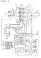
- an engine 1 includes four cylinders 1a. Cylinders 1a are connected through corresponding intake manifold branches 2 respectively to a common surge tank 3. Surge tank 3 is connected through an intake duct 4 to an airflow meter 4a and airflow meter 4a is connected to an air cleaner 5. Within intake duct 4, a throttle valve 7 driven by a step motor 6 is provided. This throttle valve 7 opens/closes intake duct 4 substantially in accordance with press-down of an accelerator pedal 10. Cylinders 1a are connected to a common exhaust manifold 8 and this exhaust manifold 8 is connected to a three-way catalytic converter 9.
- an in-cylinder injector 11 for injecting a fuel into the cylinder as well as an intake port injector 12 for injecting a fuel into an intake port or intake manifold are attached. These injectors 11, 12 are each controlled by an output signal of an electronic control unit 30. In-cylinder injectors 11 are connected to a common fuel delivery pipe 13 and fuel delivery pipe 13 is connected, through a check valve 14 allowing a flow toward fuel delivery pipe 13, to an engine-driven high-pressure fuel pump 15.
- the discharge side of high-pressure fuel pump 15 is connected through an electromagnetic spill valve 15a to the intake side of high-pressure fuel pump 15..
- this electronic spill valve 15a As the degree of opening of this electronic spill valve 15a is smaller, the amount of fuel supplied from high-pressure fuel pump 15 into fuel delivery pipe 13 is increased.
- electromagnetic spill valve 15a When electromagnetic spill valve 15a is fully-opened, the fuel supply from high-pressure fuel pump 15 to fuel delivery pipe 13 is stopped.
- electromagnetic spill valve 15a is controlled based on an output signal of electronic control unit 30.
- Intake port injectors 12 are connected to a common fuel delivery pipe 16, and fuel delivery pipe 16 and high-pressure fuel pump 15 are connected through a common fuel pressure regulator 17 to an electric-motor-driven low-pressure fuel pump 18. Further, low-pressure fuel pump 18 is connected through a fuel filter 19 to a fuel tank 20. When the pressure of fuel discharged from low-pressure fuel pump 18 becomes higher than a set fuel pressure that is determined in advance, fuel pressure regulator 17 returns a part of the fuel discharged from low-pressure fuel pump 18 to fuel tank 20. In this way, it is prevented that the pressure of fuel supplied to intake port injector 12 and the pressure of fuel supplied to high-pressure fuel pump 15 become higher than the above-described set fuel pressure. Moreover, as shown in Fig.
- an open/close valve 21 is provided between high-pressure fuel pump 15 and fuel pressure regulator 17. In a normal state, open/close valve 21 is opened. Open/close valve 21 is closed to stop fuel supply from low-pressure fuel pump 18 to high-pressure fuel pump 15. Opening/closing of open/close valve 21 is controlled based on an output signal of electronic control unit 30.
- Fig. 2 shows a side cross-sectional view of cylinder 1a.
- cylinder 1a includes a cylinder block 61, a piston 62 having its top surface where a concave 62a is formed, a cylinder head 63 secured on cylinder block 61, a combustion chamber 64 formed between piston 62 and cylinder head 63, an intake valve 65, an exhaust valve 66, an intake port 67, an exhaust port 68, a spark plug 69, and an ignitor 70.
- Intake port 67 is formed to allow air flowing into combustion engine 64 to generate swirls around the cylinder axis.
- Concave 62a extends from the portion of the periphery of piston 62 where in-cylinder injector 11 is located to the central portion of piston 62 and also extend upward below spark plug 69.
- Engine speed sensor 46 generates output pulses representing the rotation angle of a crankshaft that is the engine output shaft and accordingly representing the engine speed namely engine rpm.
- Electronic control unit 30 is constituted of a digital computer and includes a ROM (read-only memory) 32, a RAM (random-access memory) 33 and a CPU (microprocessor) 34 connected to each other through a bidirectional bus 31 as well as an input port 35 and an output port 3 6.
- Airflow meter 4a generates an output voltage proportional to an intake air quantity, and the output voltage of airflow meter 4a is input through an AD converter 37 to input port 35.
- a water temperature sensor 38 generating an output voltage proportional to an engine coolant temperature is attached, and the output voltage of water temperature sensor 38 is input through an AD converter 39 to input port 35.
- a fuel pressure sensor 40 generating an output voltage proportional to the fuel pressure in fuel delivery pipe 13 is attached, and the output voltage of fuel pressure sensor 40 is input through an AD converter 41 to input port 35.
- an air/fuel ratio sensor 42 generating an output voltage proportional to the oxygen concentration in a discharge gas is attached, and the output voltage of air/fuel ratio sensor 42 is input through an AD converter 43 to input port 35.
- Accelerator pedal 10 is connected to an accelerator press-down degree sensor 44 generating an output voltage proportional to the degree of press down of accelerator pedal 10, and the output voltage of accelerator press-down degree sensor 44 is input through an AD converter 45 to input port 35.
- engine speed sensor 46 generating an output pulse representing the engine speed is connected.
- ROM 32 of electronic control unit 30 a basic fuel injection quantity and an ignition timing value described hereinlater that are set according to an operation state as well as correction values based on the engine coolant temperature for example are mapped and stored in advance based on an engine load factor obtained from accelerator press-down degree sensor 44 or airflow meter 4a and the engine speed obtained from engine speed sensor 46.
- Output port 36 of electronic control unit 30 is connected to step motor 6, in-cylinder injectors 11 each, intake port injectors 12 each, and ignitor 70 of spark plug 69 for example through respective drive circuits 47.
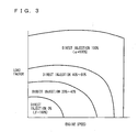
- a combustion manner or an injection manner is set in correspondence with the operation region or a condition map as shown in Fig. 3 , and ratio ⁇ and ratio ⁇ of injection from in-cylinder injector 11 and intake port injector 12 respectively are determined.
- fuel injection ratio ⁇ represents a ratio of a quantity of fuel injected from in-cylinder injector 11 to the total fuel injection quantity
- fuel injection ratio ⁇ represents a ratio of a quantity of fuel injected from intake port injector 12 to the total fuel injection quantity.
- ⁇ + ⁇ 100%.
- direct injection 40-80% means that ⁇ is set to 40-80% and ⁇ is set to 60-20%, however, values for ratio ⁇ and ratio ⁇ may be varied as appropriate, in accordance with the operation condition required to engine 1 that is used.
- Electronic control unit 30 performs various control operations including fuel injection control and ignition timing control.
- a proper ignition timing setting routine for the ignition timing is described according to the embodiment of the present invention.
- the proper ignition timing setting routine is executed for example each time the crank angle advances by a predetermined angle.
- step S401 as parameters representing an operation state of engine 1, the engine speed calculated from the measurement of engine speed sensor 46 and the engine load factor based on the degree of press-down of the accelerator detected by accelerator press-down degree sensor 44 are read.
- step S402 from basic map A stored in advance in a memory of electronic control unit 30 in association with injection manner A, a basic ignition timing value in the aforementioned operation state is obtained.
- step S403 from basic map B stored in advance in the memory of electronic control unit 30 in association with injection manner B, a basic ignition timing value in the aforementioned operation state is obtained.
- Basic map A and basic map B associated respectively with injection manner A and injection manner B are each a two-dimensional map with the vertical axis indicating the load factor and the horizontal axis indicating the engine speed as shown in Fig. 5 as (A) and (B), and each basic ignition timing value associated with an operation state is stored.
- basic map A the data of basic ignition timing value Dij for the 100% direct injection is stored and, in basic map B, the data of basic ignition timing value Pij for the 100% port injection is stored.
- basic ignition timing values Dij and Pij are each expressed by a crank angle relative to the top dead center.
- step S404 fuel injection ratio ⁇ and/or ⁇ in a current operation state is obtained from the map shown in Fig. 3 based on the engine speed and the engine load factor read in step S401. Then, in step S405, from basic map A and basic map B described above, a proper ignition timing value (D + P) ij associated with fuel injection ratio ⁇ and/or ⁇ in the current operation state is obtained by interpolation of basic ignition timing values Dij and Pij set in the maps.
- the functional elements performing steps S401 to S405 described above correspond to proper ignition timing setting means for setting a proper ignition timing in association with the fuel injection ratio between injection from in-cylinder injector 11 and injection from intake port injector 12.
- basic map A1 and basic map B2 may be used.
- Basic map A1 stores basic ignition timing values in the case where the injection is mainly the direct injection, specifically where fuel injection ratio ⁇ of the injection from in-cylinder injector 11 exceeds 50%.
- Basic map B2 stores basic ignition timing values in the case where the injection is mainly the intake port injection, specifically where the fuel injection ratio of the injection from intake port injector 12 exceeds 50%.
- a combination of basic map A and basic map B1 or a combination of basic map A1 and basic map B may be used to determine, by interpolation, a proper ignition timing value associated with fuel injection ratio ⁇ and/or ⁇ in the current operation state. In this way, the amount of data stored in memory 32 can be reduced so that a memory of a small capacity can be applied for an intended use.
- the specific value of the ignition timing differs depending on an applied engine.
- various corrections may be made based on the coolant temperature and air/fuel ratio control for example of engine 1, which is well known, and accordingly the final ignition timing is set and ignition is allowed to occur. As such corrections are well-known, a detailed description thereof will not be given here.
- step S601 a proper ignition timing value associated with a fuel injection ratio is calculated as proper ignition timing value SA2 associated with fuel injection ratio ⁇ 1 that is used for calculating the ignition timing.
- step S602 it is determined whether fuel injection ratio ⁇ in the current operation state is unequal to fuel injection ratio ⁇ 1 used for calculating the ignition timing in step S601. Namely, when they are unequal to each other and the answer is "YES,” it is determined that the operation state changes, i.e., the operation state is in a transition state, and the routine proceeds to step S603.
- step S603 performed when the operation state is in a transition state, proper ignition timing value SA1 associated with fuel injection ratio ⁇ in the current operation state is determined.
- step S604 a comparison is made between proper ignition timing value SA1 associated with fuel injection ratio ⁇ in the current operation state and proper ignition timing value SA2 associated with fuel injection ratio ⁇ 1 used for calculating the ignition timing to determine which of the ignition timing values is on the retard side.
- step S605 it is determined whether a count value of an ignition timing fixing counter exceeds a predetermined set value.
- the ignition timing fixing counter is used, when the fuel injection ratio is changed as described above, for selecting one of a proper ignition timing value before the change and a proper ignition timing value after the change that is on the retard side and setting the ignition timing at the selected ignition timing value in at least a predetermined period of time after the change.
- a predetermined period corresponding to any number of times between ten to twenty the ignition is caused to occur or the period of elapsed time may be used.
- step S605 when it is determined that the count value does not exceed the predetermined set value, the routine proceeds to step S613 in which the value of the ignition timing fixing counter is counted up and the routine proceeds to S611.
- step S611 as described above, the final ignition timing value is set at proper ignition timing value SA2 associated with fuel injection ratio ⁇ 1 for calculating the ignition timing and then the routine is ended.
- step S604 when it is determined in step S604 that proper ignition timing value SA2 associated with fuel injection ratio ⁇ 1 for calculating the ignition timing is on the advance side as compared with proper ignition timing value SA1 associated with fuel injection ratio ⁇ in the current operation state, in other words, when proper ignition timing value SA1 associated with fuel injection ratio ⁇ in the current operation state is on the retard side as compared with proper ignition timing value SA2 associated with fuel injection ratio ⁇ 1 for calculating the ignition timing, namely the answer is "NO," the routine proceeds to step S612. In step S612, fuel injection ratio ⁇ in the current operation state is made equal to fuel injection ratio ⁇ 1 for calculating the ignition timing. Then in step S614, the final ignition timing value is set at proper ignition timing value SA1 associated with fuel injection ratio ⁇ in the current operation state. The routine is then ended.
- step S605 when it is determined that the count value exceeds the predetermined set value, namely a predetermined period of time has passed since the fuel injection ratio is changed, the routine proceeds to step S606 to perform the routine of setting the ignition timing while advancing the ignition timing toward proper ignition timing value SA1 associated with current fuel injection ratio ⁇ after the fuel injection ratio is changed.
- This factor may be a constant value, a value of a quadric curve according to a change in coolant temperature of the engine or a linear value proportional to the quantity of intake air.
- step S607 a determination is made for ending the routine of setting the ignition timing while advancing it at a predetermined rate toward proper ignition timing value SA1 associated with the current fuel injection ratio ⁇ . Specifically, it is determined whether the absolute value of the difference between the current fuel injection ratio ⁇ and the fuel injection ratio ⁇ 1 for ignition timing calculation is smaller than a predetermined value. When the absolute value of the difference is not smaller than the predetermined value, namely when the answer is "NO,” the routine proceeds to step S610 in which proper ignition timing value SA2 associated with fuel injection ratio ⁇ 1 for calculating the ignition timing is determined. Then the routine proceeds to step S611 in which this proper ignition timing value SA2 is set as the final ignition timing value, as discussed above.
- step S607 when it is determined in step S607 that the absolute value of the difference between the current fuel injection ratio ⁇ and the fuel injection ratio ⁇ 1 for calculating the ignition timing is smaller than the predetermined value, namely the answer is "YES,” the routine proceeds to step S608 in which the current fuel injection ratio ⁇ and the fuel injection ratio ⁇ 1 for calculating the ignition timing are made equal to each other for ending the routine of setting the ignition timing while advancing the ignition timing at a predetermined rate toward proper ignition timing value SA1 associated with the current fuel injection ratio ⁇ . Then, in step S609, the count value of the ignition timing fixing counter is cleared.
- step S610 and S611 after step S609 is performed instead of proper ignition timing value SA2 shown in Fig. 6 and described above, proper ignition timing value SA1 associated with the current fuel injection ratio ⁇ is calculated that is set as the final ignition timing value. It is noted that, although the ignition timings are expressed differently, they are identical as a substantial ignition timing value.
- Fig. 7 shows an example of switching at. time t1 from injection manner B of 100% port injection with the fuel injection ratio ⁇ of 0% to injection manner A of 100% direct injection as well as switching at time t2 from injection manner A to injection manner B of 100% port injection.
- Fig. 7 shows an example of switching at. time t1 from injection manner B of 100% port injection with the fuel injection ratio ⁇ of 0% to injection manner A of 100% direct injection as well as switching at time t2 from injection manner A to injection manner B of 100% port injection.
- the right half shows an example of switching at time t3 from injection ratio ⁇ L with a lower direct injection ratio of the injection manner (A + B) to another fuel injection ratio ⁇ U with a higher direct injection ratio and returning at time t4 to fuel injection ratio ⁇ L.
- proper ignition timing value SA2 before the change is selected as the one that is on the retard side with respect to proper ignition timing SA1 after the change, and the selected ignition timing value SA2 is set as the final ignition timing value.
- proper ignition timing value SA2 after the change is selected as the one that is on the retard side with respect to proper ignition timing value SA1 before the change, and the selected ignition timing value SA2 is set as the final ignition timing value.
- ignition timing value SA2 on the retard side is selected and thus excessive change in output power is avoided to prevent torque shock.
- proper ignition timing value SA2 before the change is selected as the one that is on the retard side with respect to proper ignition timing value SA1 after the change, and ignition timing value SA2 is set as the final ignition timing value. In this case as well, occurrence of knocking due to excessive advance is surely prevented.
- proper ignition timing value SA2 after the change is selected as the one that is on the retard side with respect to proper ignition timing value SA1 before the change, and the selected ignition timing value SA2 is set as the final ignition timing value.
- ignition timing value SA2 on the retard side is selected so that excessively great change in output power is avoided and the torque shock can be prevented.
- the second modification is applied to the case where the injection manner is changed according to a change in operation state of engine 1, for example, a change is made from injection manner A of 100% direct injection to injection manner B of 100% port injection or a change is made from a higher fuel injection ratio of the injection from in-cylinder injector 11 to a lower one when the injection manner is (A + B).
- step S801 following the procedure of the routine of setting a proper ignition timing shown in the flowchart in Fig. 4 in the embodiment discussed above, proper ignition timing value SAn associated with the current fuel injection ratio after the change is calculated.
- step S802 proper ignition timing value SAp associated with the preceding fuel injection ratio before the change is calculated.
- step S803 it is determined which of proper ignition timing value SAn associated with the fuel injection ratio in the current operation state and proper ignition timing value SAp associated with the preceding fuel injection ratio is larger/smaller, specifically, which of the ignition timing values is on the retard side. It is noted that the ignition timing value is smaller when the amount of advance is smaller, namely when it is closer to the retard side.
- step S804 the routine proceeds to step S804 in which the proper ignition timing value SAn on the retard side is temporarily set as the final ignition timing value.
- step S805 proper ignition timing value SAp on the retard side is temporarily set as the final ignition timing value.
- step S806 it is determined whether the proper ignition timing value associated with the injection manner after the change or the fuel injection ratio after the change is selected.
- this routine is ended. In other words, the operation is continued still using proper ignition timing value SAp associated with the preceding fuel injection ratio that is set temporarily as the final ignition timing value in step S805.
- proper ignition timing value SAn associated with the injection manner after the change or the fuel injection ratio after the change is selected, namely the determination is "YES”
- the routine proceeds to steep S807 in which it is determined whether an amount of retard D exceeds a retard guard value L that is a retard limit amount.
- retard amount D is a difference between proper ignition timing value SAp associated with the preceding fuel injection ratio and proper ignition timing value SAn associated with the current fuel injection ratio, and the determination is made as to whether this the retard amount or difference exceeds retard guard value L of a predetermined magnitude.
- This retard guard value L is set for example with the purpose of preventing torque shock or abnormal combustion due to a sudden decrease in output power of engine 1 that occurs when retard amount D is excessively larger than an ideal amount.
- the retard amount may be set appropriately according to switching of the injection manner and the manner of change in fuel injection ratio as the operation state of engine 1 is changed.
- step S807 when it is determined that retard amount D is smaller than retard guard value L, such a problem as torque shock as described above does not arise. Thus, the routine is ended. In other words, the operation is performed using as the final ignition timing value the proper ignition timing value SAn associated with the current fuel injection ratio that is set temporarily as the final ignition timing value in step S804. In contrast, when it is determined in step S807 that retard amount D is larger than retard guard amount L, namely the determination is "NO,” the routine proceeds to step S808. In step S808, the ignition timing value determined by subtracting retard guard value L from proper ignition timing value SAp associated with the preceding fuel injection ratio is set as the final ignition timing value and the routine is ended.
- the left half shows an example in which switching is made at time t1 from injection manner B of 100% port injection with the fuel injection ratio ⁇ of 0% to injection manner A of 100% direct injection and switching is made at time t2 from injection manner A to injection manner B of 100% port injection.
- the right half shows an example in which a change is made at time t3 from fuel injection ratio ⁇ L with a lower ratio of the direct injection in injection manner (A + B) to fuel injection ratio ⁇ U with a higher ratio of the direct injection and the injection ratio is returned at time t4 to fuel injection ratio ⁇ L.
- the present modification of the embodiment is applied to the case where a change is made for example at time t2 from fuel injection ratio ⁇ of 100% to 0% and a change is made for example at time t4 from fuel injection ratio ⁇ U% to ⁇ L%, namely where the fuel injection ratio is changed so that fuel injection ratio ⁇ of the injection from in-cylinder injector 11 is lower than the fuel injection ratio of the injection from intake port injector 12.
- the ignition timing is retarded by retard guard value L that is at most a predetermined retard limit amount and, in at least a predetermined period or time (t7 - t2) or (t8 - t4) after the change, the ignition timing is set while retarded at a predetermined rate toward proper ignition timing value SAn after the change.
- a third modification of the embodiment of the present invention is now described with reference to the flowchart in Fig. 10 and the timing chart in Fig. 11 .
- the second modification of the embodiment is applied to the case where the injection manner is changed according to a change in operation state of engine 1, for example, injection manner A of 100% direct injection is changed to injection manner B of 100% port injection or a change is made in injection manner (A + B) from the state in which the fuel injection ratio of the injection from in-cylinder injector 11 is higher to the state in which that fuel injection ratio is lower
- the third modification is applied to the case for example where injection manner B of 100% port injection is changed to injection manner A of 100% direct injection or a change is made from the state where the fuel injection ratio of the injection from in-cylinder injector 11 is lower to the state where the ratio is higher.
- step S1001 The control starts and, in step S1001, following the procedure of the routine of setting a proper ignition timing value in the flowchart of Fig. 4 in the embodiment discussed above, proper ignition timing value SAn associated with the current fuel injection ratio after the change is calculated. Subsequently, in step S1002, proper ignition timing value SAp associated with the preceding fuel injection ratio before the change is calculated. In the following step S1003, it'is determined which of proper ignition timing value SAn associated with the fuel injection ratio in the current operation state and proper ignition timing value SAp associated with the preceding fuel injection ratio is larger/smaller, namely which of the timing values is on the retard side. It is noted again that the ignition timing value is smaller as the amount of advance is smaller and the ignition timing value is on the retard side.
- step S1004 In which this proper ignition timing value SAn on the retard side is temporarily set as the final ignition timing value.
- step S1005 proper ignition timing value SAp on the retard side is temporarily set as well, as the final ignition timing value.
- step S1006 it is determined whether a proper ignition timing value associated with the injection manner or the fuel injection ratio before the change is selected. If the determination is "NO,” this routine is ended. In other words, the operation is continued still using proper ignition timing value SAp associated with the preceding fuel injection ratio that is set temporarily as the final ignition timing value in step S 1005.
- step S1007 it is determined whether the difference between proper ignition timing value SAn associated with the current fuel injection ratio and proper ignition timing value SAp associated with the preceding fuel injection ratio, namely retard amount D with respect to proper ignition timing value SAn associated with the current fuel injection ratio, does not exceed retard guard value L as a retard limit amount. More specifically, it is determined whether or not this retard amount D does not exceed retard guard value L of a predetermined magnitude.
- retard guard value L is set to prevent torque shock and abnormal combustion due to a sudden decrease in output power of engine 1 that is caused when retard amount D is excessively larger than an ideal amount.
- retard guard value L may appropriately be set in magnitude according to switching of the injection manner and a change in fuel injection ratio according to a change in operation state of engine 1.
- step S1007 when it is determined that retard amount D is smaller than retard guard value L, such a problem of torque shock as discussed above does not arise. Then, this routine is ended. In other words, the operation is performed using, as the final ignition timing value, proper ignition timing value SAn associated with the current fuel injection ratio that is temporarily set as the final ignition timing value in step S1004. In contrast, when it is determined in step S 1007 that retard amount D is larger than retard guard value L, namely the determination is "NO,” the routine proceeds to step S 1008. In step S1008, the final ignition timing value is determined by subtracting retard guard value L from proper ignition timing value SAn associated with the current fuel injection ratio after the injection manner is changed. Then, this routine is ended.
- the left half shows an example where switching is made at time t1 from injection manner B of 100% port injection with fuel injection ratio ⁇ of 0% to injection manner A of 100% direct injection and a switching is made at time t2 from injection manner A to injection manner B of 100% port injection.
- the right half shows an example where a change is made at time t3 from fuel injection ratio ⁇ L with a lower ratio of the direct injection to fuel injection ratio ⁇ U with a higher ratio of the direct injection in the injection manner (A + B), and the fuel injection ratio is returned at time t4 to fuel injection ratio ⁇ L.
- the ignition timing is changed under control thereof, which is the same as that of the preceding modification of embodiment shown in the timing chart of Fig. 7 and the description is not repeated here.
- the present modification is applied to the case where fuel injection ratio ⁇ is changed for example at time t1 from 0% to 100% and the fuel injection ratio is changed for example at time t3 from fuel injection ratio ⁇ L% to ⁇ U%, in other words, the fuel injection ratio is changed so that fuel injection ratio ⁇ of the injection from in-cylinder injector 11 is higher than the fuel injection ratio of the injection from intake port injector 12.
- the ignition timing is advanced to the ignition timing retarded by retard guard value L that is a predetermined retard limit amount with respect to proper ignition timing value SAn associated with the fuel injection ratio after the change.
- the ignition timing is set by being advanced at a predetermined rate toward proper ignition timing value SAn after the change.
- torque shock can be prevented without excessive decrease in output power.
Abstract
Description
- The present invention relates to an ignition timing control apparatus for an internal combustion engine, and particularly to an ignition timing control apparatus for an internal combustion engine of so-called dual injection type that includes an in-cylinder injector for injecting a fuel into a cylinder and an intake port injector for injecting a fuel into an intake manifold or intake port.
- An internal combustion engine of so-called dual injection type is known from Japanese Patent Laying-Open No.
2001-020837 - Generally, for an internal combustion engine of the fuel injection type, in order to allow proper combustion to occur according to an operation state, a final ignition timing is determined by adding various corrective advance (or retard) values according to an engine state to a basic ignition timing value that is set in advance in association with the operation state and stored for example in a map. Ignition is caused to occur based on the determined final ignition timing for operation.
- Regarding the aforementioned dual-injection-type internal combustion engine, because of the difference in injection manner, namely depending on whether the injection manner is the one in which the fuel is injected from the in-cylinder injector or the one in which the fuel is injected from the intake port injector, the temperature of an air-fuel mixture and the state of mixture of the fuel in a combustion chamber could vary. A resultant problem is that, if ignition is simply caused for operation based on an ignition timing value that is set according to an operation state, the ignition timing is improper.
- For example, when the fuel is injected from the in-cylinder injector, it is likely that the fuel distribution in the combustion chamber is uneven as compared with the case where the fuel is injected from the intake port injector. If the air-fuel mixture is ignited in the state where the fuel distribution is uneven, combustion proceeds slowly in a low-fuel-concentration portion and thus the combustion rate of the air-fuel mixture tends to be slow. Even if the fuel distribution is not uneven, latent heat of the injected fuel causes the temperature of the air-fuel mixture in the cylinder to decrease, resulting in a low combustion rate. Thus, since the combustion rate of the air-fuel mixture varies depending on whether the fuel injection manner is the fuel injection by the in-cylinder injector or the fuel injection by the intake port cylinder, the ignition timing has to be set appropriately. Otherwise, such abnormal combustion as knocking occurs or the output power is insufficient.
- Further, in a transitional operation state where the injection manner is switched from the injection by the in-cylinder injector or from the injection by the intake port injector or the injection ratio between these injectors is changed, the change in injection manner or injection ratio could result in a different port wall temperature and a different inner-cylinder-wall temperature as well as a different amount of fuel sticking to the port wall, the inner cylinder wall and the top wall of the piston as compared with those in a normal state. Accordingly, the temperature of the air-fuel mixture and the state of mixture of the fuel in the combustion chamber could vary. In such a state, if the ignition timing is set to the one determined in a stable state, knocking due to excessive advance or insufficient output power due to excessive retard for example could occur because of the ignition timing that is different from a proper value.
- In view of the aforementioned conventional problems, an object of the present invention is to provide an ignition timing control apparatus for an internal combustion engine that includes an in-cylinder injector and an intake-port injector, reducing the possibilities for example of occurrence of knocking due to excessive advance and insufficient output power due to excessive retard.
- In an aspect of the present invention achieving the object above, an ignition timing control apparatus for an internal combustion engine having an in-cylinder injector and an intake port injector includes a proper ignition timing setting unit for setting a proper ignition timing according to a fuel injection ratio of injection from the in-cylinder injector and a fuel injection ratio of injection from the intake port injector.
- Here, preferably, the proper ignition timing setting unit sets a proper ignition timing according to the fuel injection ratio in a current operation state, based on at least a basic ignition timing value in a case where the fuel injection ratio of the injection from the in-cylinder injector exceeds 50% and thus the injection is mainly direct injection and a basic ignition timing value in a case where the fuel injection ratio of the injection from the intake port injector exceeds 50% and thus the injection is mainly port injection.
- Preferably, when a change is made in the fuel injection ratio, the proper ignition timing setting unit selects one of a proper ignition timing value before the change and a proper ignition timing value after the change that is on the retard side and sets, in at least a predetermined period of time after the change, the ignition timing at the selected ignition timing value.
- Preferably, when a change is made in the fuel injection ratio so that the fuel injection ratio of the injection from the in-cylinder injector is higher than the fuel injection ratio of the injection from the intake port injector, the proper ignition timing setting unit sets the ignition timing by advancing the ignition timing at a predetermined rate toward the proper ignition timing value associated with the fuel injection ratio after the change, after the predetermined period of time has passed.
- Preferably, when a change is made in the fuel injection ratio so that the fuel injection ratio of the injection from the in-cylinder injector is lower than the fuel injection ratio of the injection from the intake port injector, the proper ignition timing setting unit sets the ignition timing by retarding the ignition timing by at most a predetermined retard limit amount and thereafter retarding the ignition timing at a predetermined rate toward the proper ignition timing value associated with the fuel injection ratio after the change.
- Preferably, when a change is made in the fuel injection ratio so that the fuel injection ratio of the injection from the in-cylinder injector is higher than the fuel injection ratio of the injection from the intake port injector, the proper ignition timing setting unit sets the ignition timing at an ignition timing retarded by a predetermined retard limit amount with respect to a proper ignition timing value associated with the fuel injection ratio after the change, and thereafter setting the ignition timing by advancing the ignition timing at a predetermined rate toward the proper ignition timing value associated with the fuel injection ratio after the change.
- Regarding the ignition timing control apparatus for an internal combustion engine in an aspect of the present invention, for the internal combustion engine including an in-cylinder injector and an intake port injector, the proper ignition timing setting unit sets a proper ignition timing according to the fuel injection ratio between the injection from the in-cylinder injector and the injection from the intake port injector and accordingly ignition is caused to occur. Therefore, even if the temperature of the airfuel mixture and the state of mixture of the fuel in the combustion chamber vary due to a difference in injection manner and fuel injection ratio, the ignition is caused to occur for operation based on the ignition timing value that is set at the proper ignition timing associated with the operation state. Thus, the possibilities of occurrence of knocking due to excessive advance and insufficient output power due to excessive retard are reduced.
- Here, with the manner in which the proper ignition timing setting unit sets the proper ignition timing according to the fuel injection ratio in a current operation state based on at least the basic ignition timing value in the case where the fuel injection ratio of the injection from the in-cylinder injector exceeds 50% and thus the injection is mainly direct injection and the basic ignition timing value in the case where the fuel injection ratio of the injection from the intake port injector exceeds 50% and thus the injection is mainly port injection, the amount of data stored in a memory can be reduced and thus a memory of a smaller capacity can be applied for use.
- With the manner in which the proper ignition timing setting unit selects, when a change is made in fuel injection ratio, one of a proper ignition timing value before the change and a proper ignition timing value after the change that is on the retard side and sets the selected one as the ignition timing in at least a predetermined period after the change, occurrence of knocking can surely be prevented and, torque shock can be prevented without excessively great change in output power.
- With the manner in which the proper ignition timing setting unit sets the ignition timing, when a change is made in fuel injection ratio so that the fuel injection ratio of the injection from the in-cylinder injector is higher than the injection from the intake port injector, by advancing the ignition timing at a predetermined rate toward the proper ignition timing value associated with the fuel injection ratio after the change, after a predetermined period has passed, torque shock can be prevented without excessively great change in output power.
- Further, with the manner in which the proper ignition timing setting unit sets the ignition timing, when a change is made in fuel injection ratio so that the fuel injection ratio of the injection from the in-cylinder injector is lower than the injection from the intake port injector, by retarding the ignition timing by at most a predetermined retard limit amount and thereafter retarding the ignition timing at a predetermined rate toward the proper ignition timing value associated with the fuel injection ratio after the change, torque shock can be prevented without excessive decrease in output power.
- Furthermore, with the manner in which the proper ignition timing setting unit sets the ignition timing, when a change is made in fuel injection ratio so that the fuel injection ratio of the injection from the in-cylinder injector is higher than the fuel injection ratio of the injection from the intake port injector, by retard by a predetermined retard limit amount with respect to the proper ignition timing value associated with the fuel injection ratio after the change and thereafter advancing the ignition timing at a predetermined rate toward the proper ignition timing value associated with the fuel injection ratio after the change, torque shock can be prevented without excessive decrease in output power as the above-described manner.
-
-
Fig. 1 schematically shows a configuration of an ignition timing control apparatus for a dual-injection-type internal combustion engine according to the present invention. -
Fig. 2 is a side cross-sectional view of the engine shown inFig. 1 . -
Fig. 3 is a graph showing an example of the relation between a combustion manner that is set according to an operation region or conditions of an engine to which the present invention is applied and a fuel injection ratio between an in-cylinder injector and an intake port injector. -
Fig. 4 is a flowchart showing an exemplary ignition timing control routine according to an embodiment of the present invention. -
Fig. 5 is an example of maps storing basic ignition timing values associated with an injection manner used in the embodiment of the present invention, basic map A associated with injection manner A of 100% direct injection indicated by (A), and basic map B associated with injection manner B of 100% port injection indicated by (B). -
Fig. 6 is a flowchart showing an exemplary ignition timing control routine according to a first modification of the embodiment of the present invention. -
Fig. 7 is a timing chart showing how the ignition timing is changed under control of the ignition timing when the injection manner is changed, according to the first modification of the present invention. -
Fig. 8 is a flowchart showing an exemplary ignition timing control routine according to a second modification of the embodiment of the present invention. -
Fig. 9 is a timing chart showing how the ignition timing is changed under control of the ignition timing when the injection manner is changed, according to the second modification of the present invention. -
Fig. 10 is a flowchart showing an exemplary ignition timing control routine according to a third modification of the embodiment of the present invention. -
Fig. 11 is a timing chart showing how the ignition timing is changed under control of the ignition timing when the injection manner is changed, according to the third modification of the present invention. - Embodiments of the present invention are hereinafter described with reference to the drawings.
- Referring to
Fig. 1 that schematically shows a configuration of a dual-injection-type internal combustion engine to which an ignition timing control apparatus of the present invention is applied, anengine 1 includes fourcylinders 1a.Cylinders 1a are connected through correspondingintake manifold branches 2 respectively to acommon surge tank 3.Surge tank 3 is connected through an intake duct 4 to anairflow meter 4a andairflow meter 4a is connected to anair cleaner 5. Within intake duct 4, athrottle valve 7 driven by a step motor 6 is provided. Thisthrottle valve 7 opens/closes intake duct 4 substantially in accordance with press-down of anaccelerator pedal 10.Cylinders 1a are connected to a common exhaust manifold 8 and this exhaust manifold 8 is connected to a three-waycatalytic converter 9. - To each
cylinder 1a, an in-cylinder injector 11 for injecting a fuel into the cylinder as well as anintake port injector 12 for injecting a fuel into an intake port or intake manifold are attached. Theseinjectors electronic control unit 30. In-cylinder injectors 11 are connected to a commonfuel delivery pipe 13 andfuel delivery pipe 13 is connected, through acheck valve 14 allowing a flow towardfuel delivery pipe 13, to an engine-driven high-pressure fuel pump 15. - As shown in
Fig. 1 , the discharge side of high-pressure fuel pump 15 is connected through anelectromagnetic spill valve 15a to the intake side of high-pressure fuel pump 15.. As the degree of opening of thiselectronic spill valve 15a is smaller, the amount of fuel supplied from high-pressure fuel pump 15 intofuel delivery pipe 13 is increased. Whenelectromagnetic spill valve 15a is fully-opened, the fuel supply from high-pressure fuel pump 15 tofuel delivery pipe 13 is stopped. Here,electromagnetic spill valve 15a is controlled based on an output signal ofelectronic control unit 30. -
Intake port injectors 12 are connected to a commonfuel delivery pipe 16, andfuel delivery pipe 16 and high-pressure fuel pump 15 are connected through a commonfuel pressure regulator 17 to an electric-motor-driven low-pressure fuel pump 18. Further, low-pressure fuel pump 18 is connected through afuel filter 19 to afuel tank 20. When the pressure of fuel discharged from low-pressure fuel pump 18 becomes higher than a set fuel pressure that is determined in advance,fuel pressure regulator 17 returns a part of the fuel discharged from low-pressure fuel pump 18 tofuel tank 20.
In this way, it is prevented that the pressure of fuel supplied tointake port injector 12 and the pressure of fuel supplied to high-pressure fuel pump 15 become higher than the above-described set fuel pressure. Moreover, as shown inFig. 1 , an open/close valve 21 is provided between high-pressure fuel pump 15 andfuel pressure regulator 17. In a normal state, open/close valve 21 is opened. Open/close valve 21 is closed to stop fuel supply from low-pressure fuel pump 18 to high-pressure fuel pump 15. Opening/closing of open/close valve 21 is controlled based on an output signal ofelectronic control unit 30. -
Fig. 2 shows a side cross-sectional view ofcylinder 1a. Referring toFig. 2 ,cylinder 1a includes acylinder block 61, apiston 62 having its top surface where a concave 62a is formed, acylinder head 63 secured oncylinder block 61, acombustion chamber 64 formed betweenpiston 62 andcylinder head 63, anintake valve 65, anexhaust valve 66, anintake port 67, an exhaust port 68, aspark plug 69, and anignitor 70.Intake port 67 is formed to allow air flowing intocombustion engine 64 to generate swirls around the cylinder axis. Concave 62a extends from the portion of the periphery ofpiston 62 where in-cylinder injector 11 is located to the central portion ofpiston 62 and also extend upward belowspark plug 69.Engine speed sensor 46 generates output pulses representing the rotation angle of a crankshaft that is the engine output shaft and accordingly representing the engine speed namely engine rpm. -
Electronic control unit 30 is constituted of a digital computer and includes a ROM (read-only memory) 32, a RAM (random-access memory) 33 and a CPU (microprocessor) 34 connected to each other through abidirectional bus 31 as well as aninput port 35 and anoutput port 3 6.Airflow meter 4a generates an output voltage proportional to an intake air quantity, and the output voltage ofairflow meter 4a is input through anAD converter 37 to inputport 35. Toengine 1, awater temperature sensor 38 generating an output voltage proportional to an engine coolant temperature is attached, and the output voltage ofwater temperature sensor 38 is input through anAD converter 39 to inputport 35. Tofuel delivery pipe 13, afuel pressure sensor 40 generating an output voltage proportional to the fuel pressure infuel delivery pipe 13 is attached, and the output voltage offuel pressure sensor 40 is input through anAD converter 41 to inputport 35. To exhaust manifold 8 located upstream ofcatalytic converter 9, an air/fuel ratio sensor 42 generating an output voltage proportional to the oxygen concentration in a discharge gas is attached, and the output voltage of air/fuel ratio sensor 42 is input through anAD converter 43 to inputport 35. -
Accelerator pedal 10 is connected to an accelerator press-down degree sensor 44 generating an output voltage proportional to the degree of press down ofaccelerator pedal 10, and the output voltage of accelerator press-down degree sensor 44 is input through anAD converter 45 to inputport 35. To inputport 35,engine speed sensor 46 generating an output pulse representing the engine speed is connected. InROM 32 ofelectronic control unit 30, a basic fuel injection quantity and an ignition timing value described hereinlater that are set according to an operation state as well as correction values based on the engine coolant temperature for example are mapped and stored in advance based on an engine load factor obtained from accelerator press-down degree sensor 44 orairflow meter 4a and the engine speed obtained fromengine speed sensor 46. -
Output port 36 ofelectronic control unit 30 is connected to step motor 6, in-cylinder injectors 11 each,intake port injectors 12 each, andignitor 70 ofspark plug 69 for example throughrespective drive circuits 47. - In
engine 1 of the present embodiment, for example, a combustion manner or an injection manner is set in correspondence with the operation region or a condition map as shown inFig. 3 , and ratio α and ratio β of injection from in-cylinder injector 11 andintake port injector 12 respectively are determined. Here, fuel injection ratio α represents a ratio of a quantity of fuel injected from in-cylinder injector 11 to the total fuel injection quantity, while fuel injection ratio β represents a ratio of a quantity of fuel injected fromintake port injector 12 to the total fuel injection quantity. Here, α + β = 100%. InFig. 3 ,direct injection 100% represents a region where ratio α of injection only from in-cylinder injector 11 is set to 100%, that is, β = 0%. Meanwhile,direct injection 0% represents a region where ratio β of injection only fromintake port injector 12 is set to 100%, that is, α = 0%. Furthermore, direct injection 40-80% means that α is set to 40-80% and β is set to 60-20%, however, values for ratio α and ratio β may be varied as appropriate, in accordance with the operation condition required toengine 1 that is used. -
Electronic control unit 30 performs various control operations including fuel injection control and ignition timing control. Referring to the flowchart shown inFig. 4 , a proper ignition timing setting routine for the ignition timing is described according to the embodiment of the present invention. The proper ignition timing setting routine is executed for example each time the crank angle advances by a predetermined angle. In step S401, as parameters representing an operation state ofengine 1, the engine speed calculated from the measurement ofengine speed sensor 46 and the engine load factor based on the degree of press-down of the accelerator detected by accelerator press-down degree sensor 44 are read. Then, in step S402, from basic map A stored in advance in a memory ofelectronic control unit 30 in association with injection manner A, a basic ignition timing value in the aforementioned operation state is obtained. Further, in step S403, from basic map B stored in advance in the memory ofelectronic control unit 30 in association with injection manner B, a basic ignition timing value in the aforementioned operation state is obtained. - In the present embodiment, injection manner A corresponds to the case where the ratio of injection from in-
cylinder injector 11, namely fuel injection ratio α is equal to 100% (α = 100%) (hereinafter, also referred to as "100% direct injection"), and injection manner B corresponds to the case where the ratio of injection fromintake port injector 12 is equal to 100% (β = 100%) (hereinafter, also referred to as "100% port injection"). Basic map A and basic map B associated respectively with injection manner A and injection manner B are each a two-dimensional map with the vertical axis indicating the load factor and the horizontal axis indicating the engine speed as shown inFig. 5 as (A) and (B), and each basic ignition timing value associated with an operation state is stored. More specifically, in basic map A, the data of basic ignition timing value Dij for the 100% direct injection is stored and, in basic map B, the data of basic ignition timing value Pij for the 100% port injection is stored. Here, basic ignition timing values Dij and Pij are each expressed by a crank angle relative to the top dead center. - After steps S402 and S403 described above, the routine proceeds to step S404 in which fuel injection ratio α and/or β in a current operation state is obtained from the map shown in
Fig. 3 based on the engine speed and the engine load factor read in step S401. Then, in step S405, from basic map A and basic map B described above, a proper ignition timing value (D + P) ij associated with fuel injection ratio α and/or β in the current operation state is obtained by interpolation of basic ignition timing values Dij and Pij set in the maps. - Thus, in
electronic control unit 30, the functional elements performing steps S401 to S405 described above correspond to proper ignition timing setting means for setting a proper ignition timing in association with the fuel injection ratio between injection from in-cylinder injector 11 and injection fromintake port injector 12. - Instead of basic map A for the 100% direct injection and basic map B for the 100% port injection used in the above-discussed embodiment, basic map A1 and basic map B2 may be used. Basic map A1 stores basic ignition timing values in the case where the injection is mainly the direct injection, specifically where fuel injection ratio α of the injection from in-
cylinder injector 11 exceeds 50%. Basic map B2 stores basic ignition timing values in the case where the injection is mainly the intake port injection, specifically where the fuel injection ratio of the injection fromintake port injector 12 exceeds 50%. Alternatively, a combination of basic map A and basic map B1 or a combination of basic map A1 and basic map B may be used to determine, by interpolation, a proper ignition timing value associated with fuel injection ratio α and/or β in the current operation state. In this way, the amount of data stored inmemory 32 can be reduced so that a memory of a small capacity can be applied for an intended use. - The proper ignition timing herein refers to an ignition timing at which favorable ignition and combustion occurs when
engine 1 is operated at a predetermined fuel injection ratio (including the case where α = 0 or β = 0). The specific value of the ignition timing differs depending on an applied engine. To the proper ignition timing, various corrections may be made based on the coolant temperature and air/fuel ratio control for example ofengine 1, which is well known, and accordingly the final ignition timing is set and ignition is allowed to occur. As such corrections are well-known, a detailed description thereof will not be given here. - Thus, in the present embodiment, even if the temperature of the air-fuel mixture and the mixture state of the fuel in
combustion chamber 64 vary due to a difference in fuel injection ratio, ignition is allowed to occur based on the ignition timing value set at a proper ignition timing associated with the operation state. Therefore, the possibilities of occurrence of knocking due to excessive advance and insufficient output power due to excessive retard can be reduced. - Referring to the flowchart in
Fig. 6 , a first modification of the embodiment of the present invention is described. The first modification is applied to the case where the injection manner is changed according to a change in operation state ofengine 1, for example, where injection manner A of the 100% direct injection is changed to injection manner B of the 100% port injection or vise versa, or the case where the injection manner is A + B and a certain injection ratio α (here, β = 100 - α as seen from the above and thus only the fuel injection ratio α of the injection from in-cylinder injector 11 is herein used) is changed to another fuel injection ratio α. - The control starts and, in step S601, following the procedure of the proper ignition timing setting routine shown in the flowchart of
Fig. 4 in the above-described embodiment, a proper ignition timing value associated with a fuel injection ratio is calculated as proper ignition timing value SA2 associated with fuel injection ratio α1 that is used for calculating the ignition timing. In the following step S602, it is determined whether fuel injection ratio α in the current operation state is unequal to fuel injection ratio α1 used for calculating the ignition timing in step S601. Namely, when they are unequal to each other and the answer is "YES," it is determined that the operation state changes, i.e., the operation state is in a transition state, and the routine proceeds to step S603. - In contrast, when they are equal to each other and the answer is "NO," it is determined that the operation state is in a normal state where the operation state does not change and the routine proceeds to step S611 in which it is determined that the final ignition timing value is proper ignition timing value SA2 associated with fuel injection ratio α1 for calculating the ignition timing and the routine is ended. Here, fuel injection ratio α1 for calculating the ignition timing is a temporary injection ratio used for calculating the ignition timing and the temporary injection ratio is used until the ignition timing is corrected to a target ignition timing after a predetermined delay. As the ignition timing approaches the target ignition timing, α1 is set to α (α1 = α).
- In step S603 performed when the operation state is in a transition state, proper ignition timing value SA1 associated with fuel injection ratio α in the current operation state is determined. In the following step S604, a comparison is made between proper ignition timing value SA1 associated with fuel injection ratio α in the current operation state and proper ignition timing value SA2 associated with fuel injection ratio α1 used for calculating the ignition timing to determine which of the ignition timing values is on the retard side.
- When proper ignition timing value SA2 associated with fuel injection ratio α1 for calculating the ignition timing is on the retard side as compared with proper ignition timing value SA1 associated with fuel injection ratio α in the current operation state, the process proceeds to step S605 in which it is determined whether a count value of an ignition timing fixing counter exceeds a predetermined set value.
- The ignition timing fixing counter is used, when the fuel injection ratio is changed as described above, for selecting one of a proper ignition timing value before the change and a proper ignition timing value after the change that is on the retard side and setting the ignition timing at the selected ignition timing value in at least a predetermined period of time after the change. As the set value of the counter, a predetermined period corresponding to any number of times between ten to twenty the ignition is caused to occur or the period of elapsed time may be used.
- In step S605, when it is determined that the count value does not exceed the predetermined set value, the routine proceeds to step S613 in which the value of the ignition timing fixing counter is counted up and the routine proceeds to S611. In step S611, as described above, the final ignition timing value is set at proper ignition timing value SA2 associated with fuel injection ratio α1 for calculating the ignition timing and then the routine is ended.
- In contrast, when it is determined in step S604 that proper ignition timing value SA2 associated with fuel injection ratio α1 for calculating the ignition timing is on the advance side as compared with proper ignition timing value SA1 associated with fuel injection ratio α in the current operation state, in other words, when proper ignition timing value SA1 associated with fuel injection ratio α in the current operation state is on the retard side as compared with proper ignition timing value SA2 associated with fuel injection ratio α1 for calculating the ignition timing, namely the answer is "NO," the routine proceeds to step S612. In step S612, fuel injection ratio αin the current operation state is made equal to fuel injection ratio α1 for calculating the ignition timing. Then in step S614, the final ignition timing value is set at proper ignition timing value SA1 associated with fuel injection ratio α in the current operation state. The routine is then ended.
- In step S605 described above, when it is determined that the count value exceeds the predetermined set value, namely a predetermined period of time has passed since the fuel injection ratio is changed, the routine proceeds to step S606 to perform the routine of setting the ignition timing while advancing the ignition timing toward proper ignition timing value SA1 associated with current fuel injection ratio α after the fuel injection ratio is changed. Specifically, in step S606, fuel injection ratio α1 for calculating the ignition timing is determined by the following formula:

- This factor may be a constant value, a value of a quadric curve according to a change in coolant temperature of the engine or a linear value proportional to the quantity of intake air.
- In the subsequent step S607, a determination is made for ending the routine of setting the ignition timing while advancing it at a predetermined rate toward proper ignition timing value SA1 associated with the current fuel injection ratio α.
Specifically, it is determined whether the absolute value of the difference between the current fuel injection ratio α and the fuel injection ratio α1 for ignition timing calculation is smaller than a predetermined value. When the absolute value of the difference is not smaller than the predetermined value, namely when the answer is "NO," the routine proceeds to step S610 in which proper ignition timing value SA2 associated with fuel injection ratio α1 for calculating the ignition timing is determined. Then the routine proceeds to step S611 in which this proper ignition timing value SA2 is set as the final ignition timing value, as discussed above. - However, when it is determined in step S607 that the absolute value of the difference between the current fuel injection ratio α and the fuel injection ratio α1 for calculating the ignition timing is smaller than the predetermined value, namely the answer is "YES," the routine proceeds to step S608 in which the current fuel injection ratio α and the fuel injection ratio α1 for calculating the ignition timing are made equal to each other for ending the routine of setting the ignition timing while advancing the ignition timing at a predetermined rate toward proper ignition timing value SA1 associated with the current fuel injection ratio α. Then, in step S609, the count value of the ignition timing fixing counter is cleared.
- In steps S610 and S611 after step S609 is performed, instead of proper ignition timing value SA2 shown in
Fig. 6 and described above, proper ignition timing value SA1 associated with the current fuel injection ratio α is calculated that is set as the final ignition timing value. It is noted that, although the ignition timings are expressed differently, they are identical as a substantial ignition timing value. - For the sake of easy understanding of the first modification of the embodiment according to the control routine of the flowchart in
Fig. 6 as discussed above, it is described with reference to the timing chart inFig. 7 how the ignition timing is changed under control thereof as the injection manner is changed according to a change in operation state ofengine 1. InFig. 7 , the left half shows an example of switching at. time t1 from injection manner B of 100% port injection with the fuel injection ratio α of 0% to injection manner A of 100% direct injection as well as switching at time t2 from injection manner A to injection manner B of 100% port injection. InFig. 7 , the right half shows an example of switching at time t3 from injection ratio αL with a lower direct injection ratio of the injection manner (A + B) to another fuel injection ratio αU with a higher direct injection ratio and returning at time t4 to fuel injection ratio αL. - For example, when fuel injection ratio α is changed at time t1 from 0% to 100%, in at least a predetermined period of time after the change (t5 - t1), proper ignition timing value SA2 before the change is selected as the one that is on the retard side with respect to proper ignition timing SA1 after the change, and the selected ignition timing value SA2 is set as the final ignition timing value. Thus, occurrence of knocking due to excessive advance is surely prevented.
- In contrast, for example, when fuel injection ratio α is changed at time t2 from 100% to 0%, proper ignition timing value SA2 after the change is selected as the one that is on the retard side with respect to proper ignition timing value SA1 before the change, and the selected ignition timing value SA2 is set as the final ignition timing value. In this case, ignition timing value SA2 on the retard side is selected and thus excessive change in output power is avoided to prevent torque shock.
- Further, for example, when the fuel injection ratio is changed at time t3 from αL% to αU%, in at least a predetermined period of time after the change (t6 - t3), proper ignition timing value SA2 before the change is selected as the one that is on the retard side with respect to proper ignition timing value SA1 after the change, and ignition timing value SA2 is set as the final ignition timing value. In this case as well, occurrence of knocking due to excessive advance is surely prevented.
- In contrast, for example, when the fuel injection ratio is changed at time t4 from αU% to αL%, proper ignition timing value SA2 after the change is selected as the one that is on the retard side with respect to proper ignition timing value SA1 before the change, and the selected ignition timing value SA2 is set as the final ignition timing value. In this case as well, since ignition timing value SA2 on the retard side is selected so that excessively great change in output power is avoided and the torque shock can be prevented.
- In the timing chart shown in
Fig. 7 discussed above, when fuel injection ratio α of the injection from in-cylinder injector 11 is changed to be higher than the fuel injection ratio of the injection fromintake port injector 12, namely when the change is made at time t1 and time t3, the ignition timing is advanced, after the predetermined period of time (t5 - t1) or predetermined period of time (t6 - t3) has passed, at a predetermined rate (the magnitude thereof is determined by the factor described above) toward proper ignition timing value SA1 associated with fuel injection ratio α or fuel injection ratio αU after the change and a proper ignition timing is set in a transitional manner. This manner provides prevention of torque shock without excessively great change in output power. - Regarding a second modification of the embodiment of the present invention, a description is given with reference to the flowchart in
Fig. 8 and the timing chart inFig. 9 . The second modification is applied to the case where the injection manner is changed according to a change in operation state ofengine 1, for example, a change is made from injection manner A of 100% direct injection to injection manner B of 100% port injection or a change is made from a higher fuel injection ratio of the injection from in-cylinder injector 11 to a lower one when the injection manner is (A + B). - The control starts and in step S801, following the procedure of the routine of setting a proper ignition timing shown in the flowchart in
Fig. 4 in the embodiment discussed above, proper ignition timing value SAn associated with the current fuel injection ratio after the change is calculated. In step S802, proper ignition timing value SAp associated with the preceding fuel injection ratio before the change is calculated.
In the following step S803, it is determined which of proper ignition timing value SAn associated with the fuel injection ratio in the current operation state and proper ignition timing value SAp associated with the preceding fuel injection ratio is larger/smaller, specifically, which of the ignition timing values is on the retard side. It is noted that the ignition timing value is smaller when the amount of advance is smaller, namely when it is closer to the retard side. When it is determined that proper ignition timing value SAn associated with the current fuel injection ratio after the change is on the retard side, the routine proceeds to step S804 in which the proper ignition timing value SAn on the retard side is temporarily set as the final ignition timing value. When the proper ignition timing value SAp associated with the preceding fuel injection ratio is on the retard side, the routine proceeds to step S805 in which proper ignition timing value SAp on the retard side is temporarily set as the final ignition timing value. - Then, in step S806, it is determined whether the proper ignition timing value associated with the injection manner after the change or the fuel injection ratio after the change is selected. When the determination is "NO," this routine is ended. In other words, the operation is continued still using proper ignition timing value SAp associated with the preceding fuel injection ratio that is set temporarily as the final ignition timing value in step S805. In contrast, when proper ignition timing value SAn associated with the injection manner after the change or the fuel injection ratio after the change is selected, namely the determination is "YES," the routine proceeds to steep S807 in which it is determined whether an amount of retard D exceeds a retard guard value L that is a retard limit amount. Specifically, retard amount D is a difference between proper ignition timing value SAp associated with the preceding fuel injection ratio and proper ignition timing value SAn associated with the current fuel injection ratio, and the determination is made as to whether this the retard amount or difference exceeds retard guard value L of a predetermined magnitude. This retard guard value L is set for example with the purpose of preventing torque shock or abnormal combustion due to a sudden decrease in output power of
engine 1 that occurs when retard amount D is excessively larger than an ideal amount. In view of this, as shown inFig. 9 , the retard amount may be set appropriately according to switching of the injection manner and the manner of change in fuel injection ratio as the operation state ofengine 1 is changed. - In step S807, when it is determined that retard amount D is smaller than retard guard value L, such a problem as torque shock as described above does not arise. Thus, the routine is ended. In other words, the operation is performed using as the final ignition timing value the proper ignition timing value SAn associated with the current fuel injection ratio that is set temporarily as the final ignition timing value in step S804. In contrast, when it is determined in step S807 that retard amount D is larger than retard guard amount L, namely the determination is "NO," the routine proceeds to step S808. In step S808, the ignition timing value determined by subtracting retard guard value L from proper ignition timing value SAp associated with the preceding fuel injection ratio is set as the final ignition timing value and the routine is ended.
- In the timing chart of
Fig. 9 , as the timing chart inFig. 7 , the left half shows an example in which switching is made at time t1 from injection manner B of 100% port injection with the fuel injection ratio α of 0% to injection manner A of 100% direct injection and switching is made at time t2 from injection manner A to injection manner B of 100% port injection. The right half shows an example in which a change is made at time t3 from fuel injection ratio αL with a lower ratio of the direct injection in injection manner (A + B) to fuel injection ratio αU with a higher ratio of the direct injection and the injection ratio is returned at time t4 to fuel injection ratio αL. - Here, when fuel injection ratio α is changed at time t1 from 0% to 100% and fuel injection ratio is changed at time t3 from αL% to αU%, the ignition timing is changed under control thereof in the same manner as that in the last modification of the embodiment shown in the timing chart in
Fig. 7 , and the description thereof is not repeated here. - The present modification of the embodiment is applied to the case where a change is made for example at time t2 from fuel injection ratio α of 100% to 0% and a change is made for example at time t4 from fuel injection ratio αU% to αL%, namely where the fuel injection ratio is changed so that fuel injection ratio α of the injection from in-
cylinder injector 11 is lower than the fuel injection ratio of the injection fromintake port injector 12. More specifically, when the change is made at time t2 or time t4, the ignition timing is retarded by retard guard value L that is at most a predetermined retard limit amount and, in at least a predetermined period or time (t7 - t2) or (t8 - t4) after the change, the ignition timing is set while retarded at a predetermined rate toward proper ignition timing value SAn after the change. - In accordance with the present modification of the embodiment, without an excessive decrease in output power, torque shock can be prevented.
- A third modification of the embodiment of the present invention is now described with reference to the flowchart in
Fig. 10 and the timing chart inFig. 11 . While the second modification of the embodiment is applied to the case where the injection manner is changed according to a change in operation state ofengine 1, for example, injection manner A of 100% direct injection is changed to injection manner B of 100% port injection or a change is made in injection manner (A + B) from the state in which the fuel injection ratio of the injection from in-cylinder injector 11 is higher to the state in which that fuel injection ratio is lower, the third modification is applied to the case for example where injection manner B of 100% port injection is changed to injection manner A of 100% direct injection or a change is made from the state where the fuel injection ratio of the injection from in-cylinder injector 11 is lower to the state where the ratio is higher. - The control starts and, in step S1001, following the procedure of the routine of setting a proper ignition timing value in the flowchart of
Fig. 4 in the embodiment discussed above, proper ignition timing value SAn associated with the current fuel injection ratio after the change is calculated. Subsequently, in step S1002, proper ignition timing value SAp associated with the preceding fuel injection ratio before the change is calculated. In the following step S1003, it'is determined which of proper ignition timing value SAn associated with the fuel injection ratio in the current operation state and proper ignition timing value SAp associated with the preceding fuel injection ratio is larger/smaller, namely which of the timing values is on the retard side. It is noted again that the ignition timing value is smaller as the amount of advance is smaller and the ignition timing value is on the retard side. When it is determined here that proper ignition timing value SAn associated with the current fuel injection ratio after the change is on the retard side, the routine proceeds to step S1004 in which this proper ignition timing value SAn on the retard side is temporarily set as the final ignition timing value. When proper ignition timing value SAp associated with the preceding fuel injection ratio is on the retard side, the routine proceeds to step S1005 in which proper ignition timing value SAp on the retard side is temporarily set as well, as the final ignition timing value. - Then, in step S1006, it is determined whether a proper ignition timing value associated with the injection manner or the fuel injection ratio before the change is selected. If the determination is "NO," this routine is ended. In other words, the operation is continued still using proper ignition timing value SAp associated with the preceding fuel injection ratio that is set temporarily as the final ignition timing value in step S 1005. In contrast, when proper ignition timing value SAp associated with the injection manner or fuel injection ratio before the change is selected, namely the determination is "YES," the routine proceeds to step S1007 in which it is determined whether the difference between proper ignition timing value SAn associated with the current fuel injection ratio and proper ignition timing value SAp associated with the preceding fuel injection ratio, namely retard amount D with respect to proper ignition timing value SAn associated with the current fuel injection ratio, does not exceed retard guard value L as a retard limit amount. More specifically, it is determined whether or not this retard amount D does not exceed retard guard value L of a predetermined magnitude. As described in connection with the preceding modification, retard guard value L is set to prevent torque shock and abnormal combustion due to a sudden decrease in output power of
engine 1 that is caused when retard amount D is excessively larger than an ideal amount. In view of this, as shown inFig. 11 , retard guard value L may appropriately be set in magnitude according to switching of the injection manner and a change in fuel injection ratio according to a change in operation state ofengine 1. - In step S1007, when it is determined that retard amount D is smaller than retard guard value L, such a problem of torque shock as discussed above does not arise. Then, this routine is ended. In other words, the operation is performed using, as the final ignition timing value, proper ignition timing value SAn associated with the current fuel injection ratio that is temporarily set as the final ignition timing value in step S1004. In contrast, when it is determined in step S 1007 that retard amount D is larger than retard guard value L, namely the determination is "NO," the routine proceeds to step S 1008. In step S1008, the final ignition timing value is determined by subtracting retard guard value L from proper ignition timing value SAn associated with the current fuel injection ratio after the injection manner is changed. Then, this routine is ended.
- In the timing chart in
Fig. 11 as well, like the timing charts inFigs. 7 and9 , the left half shows an example where switching is made at time t1 from injection manner B of 100% port injection with fuel injection ratio α of 0% to injection manner A of 100% direct injection and a switching is made at time t2 from injection manner A to injection manner B of 100% port injection. The right half shows an example where a change is made at time t3 from fuel injection ratio αL with a lower ratio of the direct injection to fuel injection ratio αU with a higher ratio of the direct injection in the injection manner (A + B), and the fuel injection ratio is returned at time t4 to fuel injection ratio αL. - Here, when fuel injection ratio α is changed at time t2 from 100% to 0% and the fuel injection ratio is changed at time t4 from αU% to αL%, the ignition timing is changed under control thereof, which is the same as that of the preceding modification of embodiment shown in the timing chart of
Fig. 7 and the description is not repeated here. The present modification is applied to the case where fuel injection ratio α is changed for example at time t1 from 0% to 100% and the fuel injection ratio is changed for example at time t3 from fuel injection ratio αL% to αU%, in other words, the fuel injection ratio is changed so that fuel injection ratio α of the injection from in-cylinder injector 11 is higher than the fuel injection ratio of the injection fromintake port injector 12. More specifically, when the change is made at time t1 or time t3, the ignition timing is advanced to the ignition timing retarded by retard guard value L that is a predetermined retard limit amount with respect to proper ignition timing value SAn associated with the fuel injection ratio after the change. In at least a predetermined period (t9 - t1) or (t10 - t3) after the change, the ignition timing is set by being advanced at a predetermined rate toward proper ignition timing value SAn after the change. - In accordance with the present modification, like the above-described embodiment and modifications, torque shock can be prevented without excessive decrease in output power.
- Although the present invention has been described and illustrated in detail, it is clearly understood that the same is by way of illustration and example only and is not to be taken by way of limitation, the spirit and scope of the present invention being limited only by the terms of the appended claims.
Claims (2)
- A control apparatus for an internal combustion engine (1) including first fuel supply means (12) for supplying fuel from upstream of an intake valve (65) and a second fuel supply means (11) for directly supplying fuel into a cylinder (1a), said control apparatus comprising adjusting means (3a) for adjusting an amount of fuel supplied from said first fuel supply means (12) and an amount of fuel supplied from said second fuel supply means (11), depending on an operation state of said internal combustion engine (1),
characterized in that
said control apparatus controls an ignition timing of said internal combustion engine (1) such that said ignition timing is changed to advance at a first rate when the amount of fuel supplied from said first fuel supply means (12) is decreased and the amount of fuel supplied from said second fuel supply means (11) is increased,
while said ignition timing is changed to retard at a second rate when the amount of fuel supplied from said first fuel supply means (12) is increased and the amount of fuel supplied from said second fuel supply means (11) is decreased; said first rate being lower than said second rate. - The control apparatus for an internal combustion engine (1) according to claim 1, characterized in that in a case where said adjusting means (3a) decreases the amount of fuel supplied from said first fuel supply means (12) and increases the amount of fuel supplied from said second fuel supply means (11), said control apparatus changes said ignition timing to advance after a lapse of a predetermined period from a time when said adjusting means (3a) decreases the amount of fuel supplied from said first fuel supply means (12) and increases the amount of fuel supplied from said second fuel supply means (11).
Applications Claiming Priority (2)
| Application Number | Priority Date | Filing Date | Title |
|---|---|---|---|
| JP2004224716A JP4649142B2 (en) | 2004-07-30 | 2004-07-30 | Ignition timing control device for internal combustion engine |
| EP05767260A EP1781941A1 (en) | 2004-07-30 | 2005-07-21 | Ignition timing control apparatus for internal combustion engine |
Related Parent Applications (1)
| Application Number | Title | Priority Date | Filing Date |
|---|---|---|---|
| EP05767260.2 Division | 2005-07-21 |
Publications (2)
| Publication Number | Publication Date |
|---|---|
| EP2287463A1 true EP2287463A1 (en) | 2011-02-23 |
| EP2287463B1 EP2287463B1 (en) | 2011-12-21 |
Family
ID=34981241
Family Applications (2)
| Application Number | Title | Priority Date | Filing Date |
|---|---|---|---|
| EP05767260A Withdrawn EP1781941A1 (en) | 2004-07-30 | 2005-07-21 | Ignition timing control apparatus for internal combustion engine |
| EP10013946A Expired - Fee Related EP2287463B1 (en) | 2004-07-30 | 2005-07-21 | Ignition timing control apparatus for internal combustion engine |
Family Applications Before (1)
| Application Number | Title | Priority Date | Filing Date |
|---|---|---|---|
| EP05767260A Withdrawn EP1781941A1 (en) | 2004-07-30 | 2005-07-21 | Ignition timing control apparatus for internal combustion engine |
Country Status (5)
| Country | Link |
|---|---|
| US (1) | US7055500B2 (en) |
| EP (2) | EP1781941A1 (en) |
| JP (1) | JP4649142B2 (en) |
| CN (2) | CN1993548B (en) |
| WO (1) | WO2006011537A1 (en) |
Families Citing this family (51)
| Publication number | Priority date | Publication date | Assignee | Title |
|---|---|---|---|---|
| JP2006046084A (en) * | 2004-07-30 | 2006-02-16 | Toyota Motor Corp | Ignition timing controller for internal combustion engine |
| JP4376723B2 (en) * | 2004-07-30 | 2009-12-02 | トヨタ自動車株式会社 | Ignition timing control method for internal combustion engine |
| JP4375164B2 (en) * | 2004-08-23 | 2009-12-02 | トヨタ自動車株式会社 | Ignition timing control method for internal combustion engine |
| US20080060627A1 (en) | 2004-11-18 | 2008-03-13 | Massachusetts Institute Of Technology | Optimized fuel management system for direct injection ethanol enhancement of gasoline engines |
| US7314033B2 (en) | 2004-11-18 | 2008-01-01 | Massachusetts Institute Of Technology | Fuel management system for variable ethanol octane enhancement of gasoline engines |
| JP2006183534A (en) * | 2004-12-27 | 2006-07-13 | Toyota Motor Corp | Control device for internal combustion engine |
| US7395786B2 (en) * | 2005-11-30 | 2008-07-08 | Ford Global Technologies, Llc | Warm up strategy for ethanol direct injection plus gasoline port fuel injection |
| US8434431B2 (en) * | 2005-11-30 | 2013-05-07 | Ford Global Technologies, Llc | Control for alcohol/water/gasoline injection |
| US7412966B2 (en) | 2005-11-30 | 2008-08-19 | Ford Global Technologies, Llc | Engine output control system and method |
| US7594498B2 (en) * | 2005-11-30 | 2009-09-29 | Ford Global Technologies, Llc | System and method for compensation of fuel injector limits |
| US7406947B2 (en) | 2005-11-30 | 2008-08-05 | Ford Global Technologies, Llc | System and method for tip-in knock compensation |
| US8132555B2 (en) | 2005-11-30 | 2012-03-13 | Ford Global Technologies, Llc | Event based engine control system and method |
| US7730872B2 (en) | 2005-11-30 | 2010-06-08 | Ford Global Technologies, Llc | Engine with water and/or ethanol direct injection plus gas port fuel injectors |
| US7357101B2 (en) * | 2005-11-30 | 2008-04-15 | Ford Global Technologies, Llc | Engine system for multi-fluid operation |
| US7647916B2 (en) * | 2005-11-30 | 2010-01-19 | Ford Global Technologies, Llc | Engine with two port fuel injectors |
| US7877189B2 (en) * | 2005-11-30 | 2011-01-25 | Ford Global Technologies, Llc | Fuel mass control for ethanol direct injection plus gasoline port fuel injection |
| US7287492B2 (en) * | 2005-11-30 | 2007-10-30 | Ford Global Technologies, Llc | System and method for engine fuel blend control |
| US7302933B2 (en) * | 2005-11-30 | 2007-12-04 | Ford Global Technologies Llc | System and method for engine with fuel vapor purging |
| US7293552B2 (en) | 2005-11-30 | 2007-11-13 | Ford Global Technologies Llc | Purge system for ethanol direct injection plus gas port fuel injection |
| US7640912B2 (en) * | 2005-11-30 | 2010-01-05 | Ford Global Technologies, Llc | System and method for engine air-fuel ratio control |
| US7653475B2 (en) * | 2006-02-28 | 2010-01-26 | Toyota Jidosha Kabushiki Kaisha | Fuel injection control apparatus and control method of internal combustion engine |
| US7933713B2 (en) * | 2006-03-17 | 2011-04-26 | Ford Global Technologies, Llc | Control of peak engine output in an engine with a knock suppression fluid |
| US7389751B2 (en) * | 2006-03-17 | 2008-06-24 | Ford Global Technology, Llc | Control for knock suppression fluid separator in a motor vehicle |
| US8015951B2 (en) * | 2006-03-17 | 2011-09-13 | Ford Global Technologies, Llc | Apparatus with mixed fuel separator and method of separating a mixed fuel |
| US7647899B2 (en) * | 2006-03-17 | 2010-01-19 | Ford Global Technologies, Llc | Apparatus with mixed fuel separator and method of separating a mixed fuel |
| US7740009B2 (en) * | 2006-03-17 | 2010-06-22 | Ford Global Technologies, Llc | Spark control for improved engine operation |
| US7665428B2 (en) | 2006-03-17 | 2010-02-23 | Ford Global Technologies, Llc | Apparatus with mixed fuel separator and method of separating a mixed fuel |
| US7581528B2 (en) | 2006-03-17 | 2009-09-01 | Ford Global Technologies, Llc | Control strategy for engine employng multiple injection types |
| US7533651B2 (en) * | 2006-03-17 | 2009-05-19 | Ford Global Technologies, Llc | System and method for reducing knock and preignition in an internal combustion engine |
| US7665452B2 (en) * | 2006-03-17 | 2010-02-23 | Ford Global Technologies, Llc | First and second spark plugs for improved combustion control |
| US7578281B2 (en) * | 2006-03-17 | 2009-08-25 | Ford Global Technologies, Llc | First and second spark plugs for improved combustion control |
| US8267074B2 (en) * | 2006-03-17 | 2012-09-18 | Ford Global Technologies, Llc | Control for knock suppression fluid separator in a motor vehicle |
| US7779813B2 (en) * | 2006-03-17 | 2010-08-24 | Ford Global Technologies, Llc | Combustion control system for an engine utilizing a first fuel and a second fuel |
| JP4238890B2 (en) * | 2006-07-24 | 2009-03-18 | トヨタ自動車株式会社 | Fuel injection control device for internal combustion engine |
| US7681554B2 (en) * | 2006-07-24 | 2010-03-23 | Ford Global Technologies, Llc | Approach for reducing injector fouling and thermal degradation for a multi-injector engine system |
| US7909019B2 (en) * | 2006-08-11 | 2011-03-22 | Ford Global Technologies, Llc | Direct injection alcohol engine with boost and spark control |
| US7287509B1 (en) | 2006-08-11 | 2007-10-30 | Ford Global Technologies Llc | Direct injection alcohol engine with variable injection timing |
| US7461628B2 (en) | 2006-12-01 | 2008-12-09 | Ford Global Technologies, Llc | Multiple combustion mode engine using direct alcohol injection |
| US7969058B2 (en) | 2007-06-07 | 2011-06-28 | GM Global Technology Operations LLC | Permanent magnet motor with stator having asymmetric slots for reducing torque ripple |
| US8214130B2 (en) * | 2007-08-10 | 2012-07-03 | Ford Global Technologies, Llc | Hybrid vehicle propulsion system utilizing knock suppression |
| US7676321B2 (en) * | 2007-08-10 | 2010-03-09 | Ford Global Technologies, Llc | Hybrid vehicle propulsion system utilizing knock suppression |
| US7971567B2 (en) | 2007-10-12 | 2011-07-05 | Ford Global Technologies, Llc | Directly injected internal combustion engine system |
| US8118009B2 (en) | 2007-12-12 | 2012-02-21 | Ford Global Technologies, Llc | On-board fuel vapor separation for multi-fuel vehicle |
| US8550058B2 (en) | 2007-12-21 | 2013-10-08 | Ford Global Technologies, Llc | Fuel rail assembly including fuel separation membrane |
| US8141356B2 (en) * | 2008-01-16 | 2012-03-27 | Ford Global Technologies, Llc | Ethanol separation using air from turbo compressor |
| US7845315B2 (en) | 2008-05-08 | 2010-12-07 | Ford Global Technologies, Llc | On-board water addition for fuel separation system |
| US8096283B2 (en) * | 2010-07-29 | 2012-01-17 | Ford Global Technologies, Llc | Method and system for controlling fuel usage |
| FR2978209B1 (en) * | 2011-07-21 | 2013-07-12 | IFP Energies Nouvelles | METHOD FOR DETECTION AND ABNORMAL COMBUSTION CHARACTERIZATION FOR INTERNAL COMBUSTION ENGINES |
| JP6024882B2 (en) * | 2012-09-12 | 2016-11-16 | 三菱自動車工業株式会社 | Engine fuel injection control device |
| JP6286980B2 (en) * | 2013-09-24 | 2018-03-07 | 三菱自動車工業株式会社 | Engine control device |
| US9726106B2 (en) * | 2014-12-15 | 2017-08-08 | Ford Global Technologies, Llc | Methods and systems for high pressure port fuel injection |
Citations (7)
| Publication number | Priority date | Publication date | Assignee | Title |
|---|---|---|---|---|
| EP0892161A2 (en) * | 1997-07-18 | 1999-01-20 | Nissan Motor Company, Limited | Ignition timing control apparatus and method for internal combustion engine |
| EP0943793A2 (en) * | 1998-03-17 | 1999-09-22 | Nissan Motor Company, Limited | Control for direct fuel injection spark ignition internal combustion engine |
| JP2001020837A (en) | 1999-07-07 | 2001-01-23 | Nissan Motor Co Ltd | Fuel injection control device for engine |
| US6314940B1 (en) * | 1999-03-23 | 2001-11-13 | Daimlerchrysler Ag | Fuel feed system for a spark-ignition internal combustion engine and a method of operating such an internal combustion engine |
| EP1229235A2 (en) * | 2001-01-31 | 2002-08-07 | Toyota Jidosha Kabushiki Kaisha | Control apparatus for cylinder injection type internal combustion engine |
| EP1267070A1 (en) * | 2000-03-08 | 2002-12-18 | Toyota Jidosha Kabushiki Kaisha | Spark ignition stratified combustion internal combustion engine |
| EP1277942A2 (en) * | 2001-07-17 | 2003-01-22 | Nissan Motor Company, Limited | Control system and method for direct-injection spark-ignition engine |
Family Cites Families (13)
| Publication number | Priority date | Publication date | Assignee | Title |
|---|---|---|---|---|
| JPH02191819A (en) | 1988-04-07 | 1990-07-27 | Mazda Motor Corp | Fuel supply device for rotary piston engine |
| JPH0653728U (en) | 1992-12-22 | 1994-07-22 | マツダ株式会社 | Rotary piston engine |
| JP3430687B2 (en) * | 1994-12-15 | 2003-07-28 | マツダ株式会社 | Gas fuel engine |
| JP3758014B2 (en) * | 1999-02-18 | 2006-03-22 | 三菱自動車工業株式会社 | In-cylinder internal combustion engine |
| JP2002030970A (en) * | 2000-07-17 | 2002-01-31 | Honda Motor Co Ltd | Combustion state control device for cylinder fuel injection type internal combustion engine |
| CA2354749C (en) * | 2000-08-10 | 2006-09-12 | Honda Giken Kogyo Kabushiki Kaisha | Control system and method and engine control unit for internal combustion engine |
| JP2002227697A (en) * | 2001-01-31 | 2002-08-14 | Mitsubishi Motors Corp | Fuel injection device of internal combustion engine |
| US6644275B2 (en) * | 2001-03-12 | 2003-11-11 | Denso Corporation | Apparatus for controlling engine |
| JP3893909B2 (en) * | 2001-06-28 | 2007-03-14 | 日産自動車株式会社 | Control device for direct-injection spark-ignition internal combustion engine |
| US6851408B2 (en) * | 2002-12-25 | 2005-02-08 | Nissan Motor Co., Ltd. | Direct fuel injection engine |
| JP2005120942A (en) * | 2003-10-17 | 2005-05-12 | Nissan Motor Co Ltd | Control device for direct injection spark ignition type internal combustion engine |
| JP2005220887A (en) * | 2004-02-09 | 2005-08-18 | Toyota Motor Corp | Control device for internal combustion engine |
| JP4466337B2 (en) * | 2004-07-22 | 2010-05-26 | トヨタ自動車株式会社 | Control device for internal combustion engine |
-
2004
- 2004-07-30 JP JP2004224716A patent/JP4649142B2/en not_active Expired - Fee Related
-
2005
- 2005-07-21 CN CN2005800258417A patent/CN1993548B/en not_active Expired - Fee Related
- 2005-07-21 CN CN2010102218328A patent/CN101900065B/en not_active Expired - Fee Related
- 2005-07-21 US US11/185,697 patent/US7055500B2/en not_active Expired - Fee Related
- 2005-07-21 WO PCT/JP2005/013799 patent/WO2006011537A1/en active Application Filing
- 2005-07-21 EP EP05767260A patent/EP1781941A1/en not_active Withdrawn
- 2005-07-21 EP EP10013946A patent/EP2287463B1/en not_active Expired - Fee Related
Patent Citations (7)
| Publication number | Priority date | Publication date | Assignee | Title |
|---|---|---|---|---|
| EP0892161A2 (en) * | 1997-07-18 | 1999-01-20 | Nissan Motor Company, Limited | Ignition timing control apparatus and method for internal combustion engine |
| EP0943793A2 (en) * | 1998-03-17 | 1999-09-22 | Nissan Motor Company, Limited | Control for direct fuel injection spark ignition internal combustion engine |
| US6314940B1 (en) * | 1999-03-23 | 2001-11-13 | Daimlerchrysler Ag | Fuel feed system for a spark-ignition internal combustion engine and a method of operating such an internal combustion engine |
| JP2001020837A (en) | 1999-07-07 | 2001-01-23 | Nissan Motor Co Ltd | Fuel injection control device for engine |
| EP1267070A1 (en) * | 2000-03-08 | 2002-12-18 | Toyota Jidosha Kabushiki Kaisha | Spark ignition stratified combustion internal combustion engine |
| EP1229235A2 (en) * | 2001-01-31 | 2002-08-07 | Toyota Jidosha Kabushiki Kaisha | Control apparatus for cylinder injection type internal combustion engine |
| EP1277942A2 (en) * | 2001-07-17 | 2003-01-22 | Nissan Motor Company, Limited | Control system and method for direct-injection spark-ignition engine |
Also Published As
| Publication number | Publication date |
|---|---|
| CN1993548A (en) | 2007-07-04 |
| CN101900065A (en) | 2010-12-01 |
| WO2006011537A1 (en) | 2006-02-02 |
| US20060037581A1 (en) | 2006-02-23 |
| JP2006046085A (en) | 2006-02-16 |
| EP2287463B1 (en) | 2011-12-21 |
| CN101900065B (en) | 2012-08-15 |
| EP1781941A1 (en) | 2007-05-09 |
| US7055500B2 (en) | 2006-06-06 |
| JP4649142B2 (en) | 2011-03-09 |
| CN1993548B (en) | 2010-09-01 |
Similar Documents
| Publication | Publication Date | Title |
|---|---|---|
| EP2287463B1 (en) | Ignition timing control apparatus for internal combustion engine | |
| US7055501B2 (en) | Ignition timing control method and apparatus for internal combustion engine | |
| US7844389B2 (en) | Dual injection type internal combustion engine | |
| EP1561936A2 (en) | Control system for internal combustion engine | |
| KR100237512B1 (en) | Apparatus for controlling fuel injection in straified charge combustion engine | |
| US6019082A (en) | Air intake method and controller for engines performing stratified charge combustion | |
| US7343900B2 (en) | Ignition timing controller of internal combustion engine | |
| JPH11236836A (en) | Control device for engine | |
| US20160040618A1 (en) | Control of an internal combustion engine | |
| EP0849452B1 (en) | Apparatus and method for controlling fuel injection in internal combustion engine | |
| KR100325917B1 (en) | Combustion control device for internal combustion engine | |
| KR19980064653A (en) | Combustion control device of internal combustion engine | |
| JPH11303669A (en) | Fuel injection control device for internal combustion engine | |
| JP2020101163A (en) | Combustion control device of engine | |
| JP3307306B2 (en) | Combustion system control device for internal combustion engine | |
| JP4600607B2 (en) | Control device for internal combustion engine | |
| JP2006132399A (en) | Control device and control method for an engine with supercharger | |
| JP3362616B2 (en) | Fuel injection control device for stratified combustion internal combustion engine | |
| JP4022848B2 (en) | Fuel injection control device for internal combustion engine | |
| JP2536241B2 (en) | Air supply device for internal combustion engine | |
| JP2020159329A (en) | Internal combustion engine controller | |
| JP2006226151A (en) | Fuel injection control device of internal combustion engine |
Legal Events
| Date | Code | Title | Description |
|---|---|---|---|
| PUAI | Public reference made under article 153(3) epc to a published international application that has entered the european phase |
Free format text: ORIGINAL CODE: 0009012 |
|
| 17P | Request for examination filed |
Effective date: 20101025 |
|
| AC | Divisional application: reference to earlier application |
Ref document number: 1781941 Country of ref document: EP Kind code of ref document: P |
|
| AK | Designated contracting states |
Kind code of ref document: A1 Designated state(s): DE FR IT |
|
| RIC1 | Information provided on ipc code assigned before grant |
Ipc: F02P 5/15 20060101AFI20110412BHEP |
|
| GRAP | Despatch of communication of intention to grant a patent |
Free format text: ORIGINAL CODE: EPIDOSNIGR1 |
|
| GRAS | Grant fee paid |
Free format text: ORIGINAL CODE: EPIDOSNIGR3 |
|
| GRAA | (expected) grant |
Free format text: ORIGINAL CODE: 0009210 |
|
| RIN1 | Information on inventor provided before grant (corrected) |
Inventor name: TANAKA, HIROSHI Inventor name: MIYASHITA, SHIGEKI Inventor name: HOKUTO, HIROYUKI |
|
| AC | Divisional application: reference to earlier application |
Ref document number: 1781941 Country of ref document: EP Kind code of ref document: P |
|
| AK | Designated contracting states |
Kind code of ref document: B1 Designated state(s): DE FR IT |
|
| REG | Reference to a national code |
Ref country code: DE Ref legal event code: R096 Ref document number: 602005031829 Country of ref document: DE Effective date: 20120301 |
|
| PLBE | No opposition filed within time limit |
Free format text: ORIGINAL CODE: 0009261 |
|
| STAA | Information on the status of an ep patent application or granted ep patent |
Free format text: STATUS: NO OPPOSITION FILED WITHIN TIME LIMIT |
|
| 26N | No opposition filed |
Effective date: 20120924 |
|
| REG | Reference to a national code |
Ref country code: DE Ref legal event code: R097 Ref document number: 602005031829 Country of ref document: DE Effective date: 20120924 |
|
| REG | Reference to a national code |
Ref country code: DE Ref legal event code: R084 Ref document number: 602005031829 Country of ref document: DE Effective date: 20130410 |
|
| PGFP | Annual fee paid to national office [announced via postgrant information from national office to epo] |
Ref country code: DE Payment date: 20140716 Year of fee payment: 10 |
|
| PGFP | Annual fee paid to national office [announced via postgrant information from national office to epo] |
Ref country code: FR Payment date: 20140708 Year of fee payment: 10 |
|
| PGFP | Annual fee paid to national office [announced via postgrant information from national office to epo] |
Ref country code: IT Payment date: 20140721 Year of fee payment: 10 |
|
| REG | Reference to a national code |
Ref country code: DE Ref legal event code: R119 Ref document number: 602005031829 Country of ref document: DE |
|
| PG25 | Lapsed in a contracting state [announced via postgrant information from national office to epo] |
Ref country code: IT Free format text: LAPSE BECAUSE OF NON-PAYMENT OF DUE FEES Effective date: 20150721 Ref country code: DE Free format text: LAPSE BECAUSE OF NON-PAYMENT OF DUE FEES Effective date: 20160202 |
|
| REG | Reference to a national code |
Ref country code: FR Ref legal event code: ST Effective date: 20160331 |
|
| PG25 | Lapsed in a contracting state [announced via postgrant information from national office to epo] |
Ref country code: FR Free format text: LAPSE BECAUSE OF NON-PAYMENT OF DUE FEES Effective date: 20150731 |