EP2287816A1 - Apparatus and method for providing weather and outher alerts - Google Patents
Apparatus and method for providing weather and outher alerts Download PDFInfo
- Publication number
- EP2287816A1 EP2287816A1 EP10182846A EP10182846A EP2287816A1 EP 2287816 A1 EP2287816 A1 EP 2287816A1 EP 10182846 A EP10182846 A EP 10182846A EP 10182846 A EP10182846 A EP 10182846A EP 2287816 A1 EP2287816 A1 EP 2287816A1
- Authority
- EP
- European Patent Office
- Prior art keywords
- alert
- location
- peripheral device
- receiver
- wireless
- Prior art date
- Legal status (The legal status is an assumption and is not a legal conclusion. Google has not performed a legal analysis and makes no representation as to the accuracy of the status listed.)
- Withdrawn
Links
Images


Classifications
-
- G—PHYSICS
- G08—SIGNALLING
- G08B—SIGNALLING OR CALLING SYSTEMS; ORDER TELEGRAPHS; ALARM SYSTEMS
- G08B27/00—Alarm systems in which the alarm condition is signalled from a central station to a plurality of substations
- G08B27/006—Alarm systems in which the alarm condition is signalled from a central station to a plurality of substations with transmission via telephone network
-
- G—PHYSICS
- G01—MEASURING; TESTING
- G01W—METEOROLOGY
- G01W1/00—Meteorology
-
- Y—GENERAL TAGGING OF NEW TECHNOLOGICAL DEVELOPMENTS; GENERAL TAGGING OF CROSS-SECTIONAL TECHNOLOGIES SPANNING OVER SEVERAL SECTIONS OF THE IPC; TECHNICAL SUBJECTS COVERED BY FORMER USPC CROSS-REFERENCE ART COLLECTIONS [XRACs] AND DIGESTS
- Y02—TECHNOLOGIES OR APPLICATIONS FOR MITIGATION OR ADAPTATION AGAINST CLIMATE CHANGE
- Y02A—TECHNOLOGIES FOR ADAPTATION TO CLIMATE CHANGE
- Y02A90/00—Technologies having an indirect contribution to adaptation to climate change
- Y02A90/10—Information and communication technologies [ICT] supporting adaptation to climate change, e.g. for weather forecasting or climate simulation
Definitions
- This invention relates generally to the field of alert systems and, in its preferred embodiments, to alert systems utilizing cellular, personal communication system, or wireless telecommunication technology to deliver an alert to a person.
- NOAA Weather Radio system which is a nationwide network of radio stations operating twenty-four (24) hours per day to broadcast continuous weather information directly from the local offices of the National Weather Service.
- the NOAA Weather Radio system also broadcasts alerts for the Emergency Alert System (EAS), maintained by the Federal Communication Commission, in order to provide emergency warnings for all types of hazards, including, but not limited to, earthquakes, volcano erruptions, severe weather and nuclear war.
- EAS Emergency Alert System
- the NOAA Weather Radio system has more than 450 transmitters, covering broad areas in each of the 50 states, adjacent coastal waters, Puerto Rico, the U.S. Virgin Islands, and the U.S. Pacific Territories.
- reception of the Emergency Alert System warnings via the NOAA, Weather Radio system generally requires a special radio receiver or scanner capable of picking up its emergency warning signals.
- Tone-activated alert receivers are commonly used to monitor NOAA Weather Radio broadcasts, to provide warning of severe weather and to provide emergency and civil defense alerts.
- a tone-activated alert receiver constantly monitors the local NOAA Weather Radio broadcasts for a specific 1050 Hz emergency alert tone.
- a tone-activated alert receiver produces an audible and/or visual alarm, and activates a radio tuned to the NOAA Weather Radio broadcast. Since each NOAA Weather Radio station transmits its signals to a relatively large geographical area, older tone-activated alert receivers suffer from the disadvantage of falsely responding to alerts when the condition to which the emergency alert pertains is only relevant to other geographical areas in the broadcast area of the particular NOAA Weather Radio station transmitting the alert tone.
- SAME receivers incorporate a feature known as Specific Area Message Encoding (SAME) to decrease the frequency of false alerts.
- SAME Specific Area Message Encoding
- a SAME receiver recognizes a specific digital location code, in an emergency broadcast signal, which designates a specific locality for which alerts are relevant.
- a SAME receiver switches into alarm mode only upon receipt of an emergency broadcast signal which includes a SAME digital location code matching the preprogrammed digital code. Accordingly, SAME receivers are generally deployed in a particular, fixed location such as an individual's home or office.
- SAME receivers While these SAME receivers are useful in their fixed locations, they are not particularly useful if moved from the location for which they have been programmed. Additionally, like many individuals who cannot program a video cassette recorder (VCR), some individuals may find it difficult or inconvenient to program the SAME receiver.
- VCR video cassette recorder
- cellular or Personal Communication System (PCS) wireless telephone networks be employed to deliver emergency alerts to individuals having cellular or PCS wireless telephones because cellular and PCS telephone networks typically employ short-range, broadcast transceivers (or transmitters) which have coverage areas, or cells, of a reasonably small size, thereby enabling the delivery of emergency alerts to persons in selected areas served by particular broadcast transmitters.
- broadcast transceivers or transmitters
- delivery of emergency alert messages to selected local areas would be achieved by activating only those cellular or PCS broadcast transceivers providing coverage for the specific geographical area to which the emergency alert is relevant, instead of requiring the transmission, preprogramming, and recognition of a specific digital location code corresponding to the geographical area for which the emergency alert is relevant.
- New cellular and PCS telephone networks are currently being deployed, or have been deployed, throughout North America and Europe which are capable of transmitting alphanumeric messages and which have coverage areas providing sufficient geographical specificity to make them ideal vehicles for the delivery of location-specific, emergency alert messages.
- a network operator can send messages to a cellular or PCS telephone present in any single cell or any group of cells serviced by the transceivers of the network.
- these cellular and PCS networks be used to transmit location-specific, emergency alert messages to the cellular or PCS telephone handsets of individual users by dialing the telephone number associated with each handset and, upon answer by the cellular or PCS handset, delivering the emergency alert message to the handset.
- While cellular or PCS telecommunications systems may be an effective vehicle for conveying location-specific, emergency alert messages, such systems enable delivery of emergency alert messages to only those individuals who can figure out how get such messages via their wireless telephones.
- individuals must find their way through a myriad of icons (which many individuals cannot do) and then review all of their messages in order to identify the emergency alert messages from other messages.
- the delivery of emergency alert messages via cellular or PCS telecommunications systems requires individuals to have their handsets nearby and turned-on (and not depleted of battery power).
- individuals often turn-off their handsets, forget to recharge them, or leave their handsets, for instance, in the car while they are at home or work.
- a system which relies upon cellular or PCS handset receivers to receive emergency alert messages may fail to notify a large number of individuals of the existence of an emergency condition.
- the present invention comprises an alert apparatus and method for receiving a location-specific alert (i.e., an alert directed and relevant to a particular geographical area) and for informing a user, who may be visually or hearing impaired, of the existence and severity of the alert. More particularly, the present invention includes an alert apparatus and method which allow a user to receive data corresponding to an alert which has been broadcast via particular transmitters operating within a cellular, PCS, or wireless telephone communications network, thereby allowing receipt of a location-specific alert (and a textual message associated with the alert) without requiring the user to input, to the alert apparatus, data representative of or identifying the location of the apparatus.
- a location-specific alert i.e., an alert directed and relevant to a particular geographical area
- the present invention includes an alert apparatus and method which allow a user to receive data corresponding to an alert which has been broadcast via particular transmitters operating within a cellular, PCS, or wireless telephone communications network, thereby allowing receipt of a location-specific alert (and a textual message associated with the alert
- the present invention includes an alert apparatus and method which produces high-decibel level audible sounds and high-intensity flashing strobe light corresponding to alerts of the most severe level and which produces low-decibel level audible sounds and low-intensity flashing light from a light-emitting diode corresponding to alerts of a less severe level.
- the apparatus of the present invention comprises an alert device having a microcomputer which directs operation of the alert device according to the instructions of a computer software program stored therein.
- the alert device also includes a receiver which receives digital PCS transmissions broadcast over a PCS or cellular telecommunication network.
- the microcomputer has a central processing unit and a monitoring circuit communicatively connected to the central processing unit and receiver.
- the monitoring circuit is capable of setting the receiver to receive transmissions, if any, on radio channels identified by the central processing unit, of determining the signal strength associated with transmissions received on such radio channels, of identifying the presence of a digital control channel on a radio channel, and of communicating signal strength information, digital control channel information, and broadcast short messages, received by the receiver, to the central processing unit
- the alert device further comprises a plurality of peripheral devices and the microcomputer further comprises a peripheral device controller which connects to the plurality of peripheral devices.
- the plurality of peripheral devices includes a liquid crystal display, a high-level audio speaker, a low-level audio speaker, a high-intensity strobe light, and a low-intensity light-emitting diode.
- the microcomputer via the peripheral device controller, controls the operation of the plurality of peripheral devices according to the severity of a condition identified by an alert.
- the microcomputer causes the production of audible sound from the high-level audio speaker at a high-decibel level and flashing of the high-intensity strobe light to warn a user of the existence of a "Level One" alert (i.e., the most severe or important alert condition).
- the microcomputer causes the production of audible sound from the low-level audio speaker at a low-decibel level and flashing of the low-intensity light-emitting diode to warn a user of the existence of a "Level Two" alert (i.e., a less severe or less important alert condition).
- the microprocessor via the peripheral device controller, also causes the display, on the liquid crystal display, of textual information, received as part of an alert message.
- the alert device in accordance with the preferred embodiment, is operable to continuously monitor broadcasts from a cellular, PCS, or wireless telecommunications network. Accordingly, the alert device connects to an electrical outlet to receive electrical power for normal operation, but includes a battery backup and charging circuit to ensure operation of the alert device even in the event of a power failure. Furthermore, in the referred embodiment, the alert device operates continuously when supplied with electrical power, has no on/off switch, and thus cannot easily be deactivated by a user unlike a cellular or PCS telephone handset. The alert device does, however, include a reset pushbutton which enables a user to temporarily deactivate, or stop, the audible and visual alarms once notified of an alert condition.
- the alert device is mountable to an electrical wall socket in a manner substantially similar to that of a conventional smoke detector.
- the alert device has an enclosure which enables the device to reside atop a table or other surface in a manner substantially similar to that of a weather radio.
- the alert device includes a plurality of peripheral devices which are locatable at sites remote from the alert device.
- the alert device operates according to the instructions of a computer software program residing in the microcomputer and performs a self-test when powered-up to determine whether the alert device is functioning properly.
- the alert device thorough cooperation between the microcomputer, monitoring circuit, and receiver, then scans a factory-set, pre-identified set of radio channels comprising a range of charnels used by compatible cellular or PCS telecommunication networks in order to identify the channel associated with the cellular or PCS transmitter which transmits on a digital control channel and which has the strongest signal strength at the location of the alert device.
- the alert device then locks onto and passively monitors the selected channel for digital alerts in the form of broadcast short messages. Because the alert device passively monitors PCS network broadcasts, use of the alert device should not result in the user incurring periodic service charges from the network provider.
- the alert device upon detecting and receiving a broadcast short message, identifies whether the broadcast short message comprises an alert message. If so, the alert device then analyzes the alert message and determines the severity level of the alert identified by the alert message. If the alert is a "Level One" alert, the alert device operates, as described above, the high-level audio speaker to produce a highly obtrusive, high-decibel level sound substantially similar to that of a conventional smoke detector (i.e., a sound that would cause even the hardest of sleepers to awaken) and the high-intensity strobe light to produce flashing, high-intensity, bright light.
- a conventional smoke detector i.e., a sound that would cause even the hardest of sleepers to awaken
- the high-intensity strobe light to produce flashing, high-intensity, bright light.
- the alert device operates, as described above, the low-level audio speaker to produce a less-obtrusive, low-decibel level, "chirping" sound and the low-intensity liglit-emitting diode to produce less-intense, less-bright” flashing light.
- the alert device extracts textual message information, if any, from the alert message and displays the textual message information on the liquid crystal display to provide a user with a more detailed explanation as to the nature of the alert.
- Another object of the present invention is to provide an apparatus and method for receiving location-specific alert information which is not limited to a fixed location.
- Still another object of the present invention is to provide an apparatus for receiving location-specific alert information which can be moved from an old location to a new location without requiring reprogramming or the input of data representative of the new location.
- Still another object of the present invention is to provide an apparatus for receiving location-specific alert information which self-identifies the strongest source of such alert information.
- Still another object of the present invention is to provide an apparatus for receiving location-specific alert information which self-identifies the frequency on which the alert information is transmitted or broadcast.
- Still another object of the present invention is to provide an apparatus and method for receiving location-specific alert information which identifies the different levels of severity associated with alerts.
- Still another object of the present invention is to provide an apparatus and method for receiving location-specific alert information which produces different sensory outputs corresponding to the different levels of severity or importance of alerts.
- Still another object of the present invention is to provide an apparatus and method for receiving location-specific alert information which operates continuously, unless moved by a user, at a particular location.
- Still another object of the present invention is to provide an apparatus and method for receiving location-specific alert information which is continuously operable from an external electrical power source and which has an internal battery backup for use during power failures.
- Still another object of the present invention is to provide an apparatus and method for receiving location-specific alert information which displays a textual message related to the alert for which the alert information pertains.
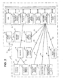
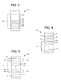
- an alert device 20 in accordance with an apparatus of the preferred embodiment of the present invention, is shown in pictorial form in FIG. 1 and in block diagram form in FIG. 2 .
- the alert device 20 comprises an enclosure 22 and a microcomputer 24, receiver 26, diversity receive antenna 28, power supply 30, and backup battery 32 residing therein.
- the enclosure 22 is manufactured from a durable plastic material and the alert device 20 is directly pluggable into an electrical wall outlet through use of an electrical plug 34 located on the back of the enclosure 22, thereby avoiding the need for mounting hardware and the difficulties of mounting the enclosure 22 to a wall.
- the receiver 26 is adapted to receive digital signals within the ranges of channels utilized for cellular, PCS, or other wireless communications in the area in which the alert device 20 is deployed.
- the receiver 26 is adapted to receive digital signals on channels having receive-side frequencies in the (i) 969 MHz to 994 MHz range, (ii) 1840 MHz to 1865 MHz range, (iii) 1930.72 MHz to 1945 MHz range, (iv) 1950.72 MHz to 1965 MHz range, or (v) 1975.72 MHz to 1990 MHz range.
- the scope of the present invention includes similar receivers which are adapted to receive cellular, PCS, or wireless digital signals in any frequency range.
- the alert device 20 further comprises a plurality of peripheral devices 36 which electrically connect to the microcomputer 24, and an external antenna 38 having a first portion which resides within the enclosure 22 and a second portion which extends outside of the enclosure 22.
- An external antenna 38 acceptable in accordance with the preferred embodiment, is a rubber-covered antenna commonly known as a "rubber duck antenna" which is often found in cellular PCS, or wireless telephones.
- the plurality of peripheral devices 36 includes a liquid crystal display 36a residing within the enclosure 22 adjacent to an opening 40 in the enclosure 22 which enables the liquid crystal display 36a to be visible from outside the enclosure 22.
- the liquid crystal display 36a is backlit to enhance the readability of the display 36a.
- the liquid crystal display 36a has signal strength indicator 37 located near the right side of the display 36a.
- the signal strength indicator 37 comprises a plurality of liquid crystal bars 39 arranged in a, generally, vertical direction which the microcomputer 24 energizes to darken the bars 39 and, thereby indicate the signal strength of the strongest channel received by the alert device 20 at the device's then-existing location. A stronger signal strength is indicated by energization and darkening of a larger number of bars 39, while a weaker signal is indicated by energization and darkening of a smaller number of bars 39.
- the plurality of peripheral devices 36 also includes a high-level audio speaker 36b and a low-level audio speaker 36c which reside within the enclosure 22 at positions adjacent respective grill-like openings 42, 44 in the enclosure 22 that allow audible sounds generated by the speakers 36b, 36c to exit the enclosure 22 to the environment surrounding the emergency alert device 20.
- the high-level audio speaker 36b includes a speaker, substantially similar to those found in smoke detectors, which produces a high-decibel level continuous or pulsating tone that is sufficiently loud to awaken a sleeping person.
- the low-level audio speaker 36c includes a speaker which, when appropriately activated, emits a periodic "chirp-type" sound substantially similar to the sound emitted by the speakers employed in portable pagers.
- the plurality of peripheral devices 36 additionally includes a high-intensity strobe light 36d and a low-intensity light emitting diode (LED) 36e which reside within the enclosure 22 and are visible, through a window-covered opening 46, from outside the enclosure 22.
- the high-intensity strobe light 36d in accordance with the apparatus of the preferred embodiment, includes a conventional xenon flash tube which is pulsable in a periodic manner to produce a bright flash of light every one to two seconds when in use, thereby enabling the alert device 20 to draw the attention of a bearing impaired person.
- the low-intensity light emitting diode 36e includes a conventional, red light emitting diode which is pulsable in a manner similar to that employed with the high-intensity strobe light 36d.
- the plurality of peripheral devices 36 further includes a reset pushbutton 36f which extends through an opening in the enclosure 22 so as to be depressable by a user of the alert device 20.
- the microcomputer 24 comprises, preferably, a custom-manufactured device substantially similar to those microcomputers residing in cellular, PCS, or wireless telephones and includes, integrated therein, a central processing unit (CPU) 60, a monitoring circuit 62, a non-volatile program memory 64, a non-volatile data memory 66, a volatile data memory 68, a peripheral device controller 70, and a count-down timer 72.
- the non-volatile program memory 64 illustrated in FIG.
- a computer software program 200 having a main portion 210, a self-test routine 400, a high-level alarm routine 500, a low-level alarm routine 600, a timer interrupt handling routine 700, and a reset interrupt handling routine 800 which the CPU 60 executes, as described below, to cause the alert device 20 to operate in accordance with a method of the preferred embodiment of the present invention.
- the non-volatile data memory 66 stores values for the starting channel identifier 76 and the ending channel identifier 78 of the range of channels to be monitored, or scanned, by the receiver 26 for the presence of a digital control channel as described below.
- the non-volatile data memory 66 also stores the value of the test channel step-size 80 and a plurality of receive frequencies 82 corresponding in a one-to-one relationship with channels to be possibly monitored by the receiver 26 (i.e., so that receive frequency 82a corresponds to the first channel possible for monitoring, receive frequency 82b corresponds to the second channel possible for monitoring, and receive frequency 82n corresponds to the n th channel possible for monitoring.
- the non-volatile data memory 66 stores a plurality of receive frequencies 82 corresponding to the channels associated with the receive-side frequencies in (i) the 969 MHz to 994 MHz range, (ii) the 1840 MHz to 1865 MHz range, (iii) the 1930.72 MHz to 1945 MHz range, (iv) the 1950.72 MHz to 1965 MHz range, or (v) the 1975.72 MHz to 1990 MHz range.
- the non-volatile data memory 66 also stores a self-test time period 81 which defines the amount of time that the self-test routine 400 delays at various steps during execution.
- the volatile data memory 68 stores a plurality of channel identifers 84 and a plurality of signal strength values 86 organized in a list, or table, 88 of plurality of channel identifier/signal strength pairs 90.
- Each channel identifier/signal strength pair 90 comprises a channel identifier 84 and a respective signal strength value 86 which represent a number identifying a digital control channel found and the associated signal strength value 86 (also referred to herein as "signal strength") identified by the receiver 26 and monitoring circuit 62 as described below.
- the volatile data memory 66 also stores a test channel identifier 91 and a pointer 93 to the digital control channel selected as described below (also referred to herein as a "alert channel pointer 93").
- the peripheral device controller 70 is an intelligent controller which produces, at appropriate times described below, signals necessary to cause operation of each peripheral device 36 of the plurality of peripheral devices 36 as described herein.
- the peripheral device controller 70 produces, when necessary, signals necessary to cause the high-level audio speaker 36b to generate an obtrusive tone which should wake the soundest of sleepers, the low-level audio speaker 36c to generate "chirping" sounds, and the bigh-intensity strobe light 36d and the low-intensity light-emitting diode 36e to flash.
- the peripheral device controller 70 also ceases, at appropriate times described below, the production of signals which cause operation, for instance, of the high-level audio speaker 36b, the low-level speaker 36c, the high-intensity strobe light 36d, and the low-intensity light-emitting diode 36e.
- the count-down timer 72 comprises a timer which is programmable by the CPU 60 to start counting down time from an initial time provided to the count-down timer 72 by the CPU 60. Upon reaching zero, the count-down timer 72 produces an interrupt signal which is communicated to the CPU 60.
- the reset pushbutton 36f also produces an interrupt signal which is communicated to the CPU 60.
- the microcomputer 24, as displayed in FIG. 2 further includes a bus 74 which interconnects the CPU 60 and the monitoring circuit 62, non-volatile program memory 64, non-volatile data memory 66, volatile data memory 68, peripheral device controller 70, and count-down timer 72 for the communication of address, data, and control signals (including interrupt signals) therebetween.
- the monitoring circuit 62 communicatively connects to the receiver 26 through signal lines 92.
- Receiver 26 electrically connects, via respective signal lines 94, 96, to the diversity receive antenna 28 and the external antenna 38.
- the peripheral device controller 70 communicatively connects to the liquid crystal display 36a, the high-level audio speaker 36b, the low-level audio speaker 36c, the high-intensity strobe light 36d, the low-intensity light emitting diode (LED) 36e, and the reset pushbutton 36f through respective signal lines 98, 100, 102, 104, 106, 108.
- the power supply 30 connects, via electrical conductors 110, to electrical plug 34 for the receipt of alternating-current electrical power.
- the power supply 30 converts the alternating-current electrical power into direct-current electrical power at appropriate voltages.
- the power supply 30 also connects to the microcomputer 24, the receiver 26, and the plurality of peripheral devices 36, where necessary (although not shown in FIG. 2 ), for the delivery of direct-current electrical power thereto at appropriate voltages.
- the power supply 30 includes a charging and switching circuit 112 therein which bi-directionally connects to the backup battery 32 through conductors 114.
- the charging and switching circuit 112 charges the backup battery 32, if necessary, by delivering direct-current electrical power to the backup battery 32 through conductors 114.
- the backup battery 32 supplies direct-current electrical power to the charging and switching circuit 112 through conductors 114 for subsequent delivery to the microcomputer 24, the receiver 26, and the plurality of peripheral devices 36, where necessary.
- the receiver 26 further includes those receivers capable of receiving digital cellular, PCS, or wireless telecommunication signals corresponding to alert messages 130 (described below) broadcast from cellular, PCS, or wireless telecommunication transmitters 120 residing on towers 122 that are positioned to provide cellular, PCS, or wireless telecommunications services for respective, localized, and identifiable geographical areas 124 as illustrated pictorially in FIG. 6 .
- the alert messages 130 are produced, prior to their reception by a receiver 26, by an alert messaging system.
- An alert messaging system is, typically, operated by a governmental authority and comprises telecommumications equipment, computer hardware and computer software which: (i) receives an alert from a source, for instance, the Emergency Alert System or National Weather Service or Department of Defense, (ii) determines whether one or more alert messages 130 corresponding to the alert should be broadcast, (iii) identifies the appropriate telecommunications transmitters 120 (and, hence, the geographical areas 124) to which the alert message(s) 130 should be delivered, (iv) builds and formats the alert message(s) 130 appropriately, and (v) communicates the alert message(s) 130 to a cellular, PCS, or wireless telecommunications network for routing of the alert message(s) 130 to the identified telecommunications transmitter(s) 120 which, subsequently, broadcast the alert message(s) 130 to their respective geographical area(s) 124.
- a source for instance, the Emergency Alert System or National Weather Service or Department of Defense
- determines whether one or more alert messages 130 corresponding to the alert should be broadcast identifies
- the alert messages 130 received by receiver 26 and acted upon, as described below, by the alert device 20 include, according to the preferred embodiment of the present invention, messages 130 which are encoded by the alert messaging system according to the Broadcast Short Messages System in the format of a PCS short message (illustrated by the schematic data representation of FIG. 7 ).
- Each alert message 130 includes a message header 132 indicating that the message 130 includes alert data and the general level of the alert.
- the header 132 comprises eight (8) bytes of data, including a three (3) byte market code 134, a two (2) byte zone code 136, a two (2) byte alert level code 138, and a one (1) byte date stamp 140.
- the market code 134 includes data which identifies the regional market for which the alert message 130 is intended (i.e., the regional market includes a plurality of telecommunication transmitters 120 located in the geographical region identified by the regional market code).
- the zone code 136 comprises data which identifies the particular telecommunication transmitter 120 within the regional market that is to broadcast the alert message 130.
- the market code 134 and the zone code 136 are used by the cellular, PCS, or wireless telecommunications network, as described above for routing and communication of the alert message 130 to the telecommunications transmitter(s) 120 and geographical area 124 identified as appropriate by the alert messaging system.
- the alert level code 138 of each alert message 130 includes data which identifies the severity and type of the alert condition.
- the EAS AM & FM Handbook published by the Federal Communication Commission of the United States divides the alerts sent out by the Emergency Alert System ("EAS") (referred to herein as “emergency alerts") into three (3) general levels of severity.
- EAS Emergency Alert System
- a "Level Zero" emergency alert i.e., signified by an alert message 130 in which the alert level code 138 has a value of four (4) indicates the existence of no emergency alert conditions and that previous emergency alerts are no longer valid or no longer in effect.
- a “Level One” alert (i.e., signified by an alert message 130 in which the alert level code 138 has a value of five (5)) indicates the existence, in the geographical area 124.to which the alert message 130 pertains and is communicated, of an emergency situation posing an extraordinary threat to the safety of life or property such as, but not limited to, the existence, or imminent existence, of a tornado, flood, fire, discharge of hazardous materials, industrial explosion, or nuclear incident.
- a “Level Two” emergency alert (i.e., signified by an albert message 130 in which the alert level code 138 has a value of six (6)) indicates the issuance of a severe weather watch or that a particular emergency condition is possible in the geographical area 124 to which the emergency alert is communicated via telecommunication transmitters 120.
- the alert level code 138 when appropriate, contains values other than those values described above to indicate other types of alerts and the respective seventy of such other types of alerts.
- a "Level One" military alert i.e., signified by an alert message 130 in which the alert level code 138 has a value of seven (7) indicates the existence, for the geographical area 124 to which the alert message 130 pertains and is communicated, of an extremely important military alert (as an example, an alert requiring that all active duty military personnel and reservists report to their bases immediately).
- a "Level Two" military alert i.e., signified by an alert message 130 in which the alert level code 138 has a value of eight (8) indicates the existence, for the geographical area 124 to which the alert message 130 pertains and is communicated, of a less-important military alert (as an example, an alert requesting that all reservists report on Sunday instead of Saturday). It is understood that the scope of the present invention includes other types and severities of alerts having different values for alert level code 138.
- Each alert message 130 further includes a text message string 142 which follows the message header 132.
- the text message string 142 preferably, includes a maximum of 160 ASCII text characters for display on the liquid crystal display 36a of the alert device 20 and provides more detailed information or instructions related to an alert condition. Because each alert message 130 is broadcast by one or more particular telecommunications transmitters 120 to alert devices 20 present in a specific, identifiable geographical area 124, information relevant to that geographical area 124 is includable in the text message string 142.
- an alert message 130 sent and broadcast to that area includes a text message string 142 storing a message such as "TAKE IMMEDIATE COVER - A TORNADO STRIKE MAY BE IMMINENT IN THE DUNWOODY, GEORGIA AREA!.
- alert message text strings 142 include, for example and not limitation, messages such as "SEVERE THUNDERSTORMS WILL MOVE INTO YOUR AREA WITHIN 30 MINUTES”, “FLASH FLOODS ARE POSSIBLE IN YOUR AREA”, “ALL ALERTS FOR YOUR AREA HAVE LAPSED”, “AN ESCAPED CONVICT IS ON THE LOOSE IN YOUR AREA - PLEASE LOCK ALL DOORS AND WINDOWS”, or other relevant messages.
- the alert device 20 operates, in accordance with a preferred method of the present invention, as illustrated in FIGS. 8-13 .
- the alert device 20 In response to a user plugging the electrical plug 34 into an electrical outlet, the alert device 20 initiates operation at step 212 where the CPU 60 of the microcomputer 24 begins to execute the instructions of the main portion 210 of the computer software program 200 residing in non-volatile program memory 64, thereby causing the alert device 20 to function as set forth in FIG. 8 .
- the CPU 60 executes, at step 214, the instructions of a self-test routine 400 (illustrated in FIG.
- step 9 which tests the alert device's 20 ability to display messages on the liquid crystal display 36a, to produce appropriate tones on the high-level audio speaker 36b and the low-level audio speaker 36c, and to generate flashing light from the high-intensity strobe light 36d and the low-intensity light-emitting diode 36e.
- operation of the alert device 20 advances to step 216.
- the CPU 60 reads from the non-volatile data memory 66, at step 216, the starting channel identifier 76 of the range of channels to be monitored, or scanned, by the receiver 26 for the presence of a digital control channel.
- the CPU 60 sets the test channel identifier 91 of volatile data memory 68 to the value of the starting channel identifier 76 and then sets the monitoring circuit 62 and receiver 26 to monitor, or scan, the test channel identified by the test channel identifier 91 by (i) identifying the receive frequency 82 corresponding to the test channel through performance of a table lookup operation using the test channel identifier 91 and the plurality of receive frequencies 82 stored in non-volatile data memory 66 and by (ii) communicating the looked-up receive frequency 82 to the monitoring circuit 62 via bus 74.
- the monitoring circuit 62 sets the frequency to be received by the receiver 26 by communicating the receive frequency 82 to the receiver 26 via signal lines 92.
- the receiver 26 then commences reception of signals on the receive frequency 82 and provides output on signal lines 92 to the monitoring circuit 62, including the signal strength of the channel currently being monitored by the receiver 26.
- the monitoring circuit 62 Upon receiving output from the receiver 26, the monitoring circuit 62, at step 220, analyzes the output from the receiver 26 to determine whether a digital control channel is present on the test channel identified by the test channel identifier 91. If so, the monitoring circuit 62 so informs the CPU 60 and the CPU 60 stores the test channel identifier 91 in the plurality of channel identifiers 84 of the volatile data memory 68 at step 222.
- the CPU 60 reads the signal strength value 86 from the monitoring circuit 62, via bus 74, and stores the signal strength value 86 in volatile data memory 68 in association with the test channel identifier 91 stored at step 222 (i.e., as one channel identifier/signal strength pair 90 of the plurality of channel identifier/signal strength pair 90). If not, the CPU 60 determines, at step 226, whether the test channel identifier 91 equals the ending channel identifier 78.
- test channel identifier 91 does not equal the ending channel identifier 78, the CPU 60 increments the test channel identifier 91 of volatile data memory 68 by the test channel step-size 80 of non-volatile data memory 66 at step 228 and loops back to step 218 in order to set the monitoring circuit 62 and receiver 26 to monitor, or scan, the test channel identified by the incremented test channel identifier 91.
- the CPU 60 determines that the test channel identifier 91 equals the ending channel identifier 78, all of the channels have been monitored for the presence of a digital control channel and the CPU 60 then determines, at step 230, whether any digital control channels have been found by reviewing the table 88 of the plurality of channel identifier/signal strength pairs 90 for the presence of channel identifiers 84 and signal stength values 86. If the CPU 60 determines, at step 230, that no digital control channels have been found (i.e., that table 88 contains no channel identifiers 84 and signal strength values 86), the CPU 60 instructs, at step 232, the peripheral device controller 70 to display "NO SERVICE AVAILABLE" on the liquid crystal display 36a. The CPU 60 then loops back to step 216.
- the CPU 60 determines, at step 230, that a digital control channel has been found, the CPU 60 then, at step 236, analyzes and compares the signal strength values 86 stored in volatile data memory 68 to identify and select the digital control channel having the strongest signal strength value 86 (the digital control channel so identified being referred to herein as the "alert channel"). At step 238, the CPU 60 stores the channel identifier 84 of the alert channel as the alert channel pointer 93 in volatile data memory 68.
- the CPU 60 sets the monitoring circuit 62 to monitor the alert channel by retrieving the receive frequency 82 corresponding to the alert channel (referred to herein as the "alert channel receive frequency") using the alert channel pointer 93 and the plurality of receive frequencies 82 stored in non-volatile data memory 66 and by communicating the alert channel receive frequency to the monitoring circuit 62 via bus 74.
- the monitoring circuit 62 sets the receiver 26 to receive signals at the alert channel receive frequency, by communicating the alert channel receive frequency to the receiver 26 through signal lines 92.
- the CPU 60 causes the graphical display of the signal strength of the alert channel by instructing the peripheral device controller 70 to energize the appropriate bars 39 of the signal strength indicator 37 of the liquid crystal display 36a.
- the alert device 20 enables a user to move the alert device 20 to other locations (for instance, in the user's house) and to visually see any change in signal strength, thereby further enabling a user to select a location for the alert device 20 at which the alert device 20 receives the maximum possible signal strength for the alert channel.
- the CPU 60 instructs the peripheral device controller 70, via bus 74, to display the word "READY" in the alphanumeric portion of the liquid crystal display 36a.
- the peripheral device controlled 70 communicates an appropriate command to the liquid crystal display 36a, via signal lines 98, causing the liquid crystal display 36a to display the word "READY".
- the monitoring circuit 62 continually monitors, at step 246, the alert channel for the presence of a broadcast short message until the monitoring circuit 62 detects a broadcast short message.
- the monitoring circuit 62 Upon detection of a broadcast short message, the monitoring circuit 62 notifies the CPU 60 of the receipt of the broadcast short message at step 248 and, in response, the CPU 60 reads the header 132 of the broadcast short message.
- the CPU 60 at step 250, analyzes the header 132 and determines whether the broadcast short message is an alert message 130 by comparing the format and data of the received broadcast short message to the format and data values known to the CPU 60 as corresponding to an alert message 130.
- the CPU 60 determines that the broadcast short message is not an alert message 130, the CPU 60 branches back to step 246 to resume monitoring of the alert channel. If the CPU 60 determines that the broadcast short message is an alert message 130, the CPU 60 identifies the alert level of the alert message 130 by extracting the alert level code 138 from the alert message 130 at step 252.
- the CPU 60 determines whether the alert level code 138 corresponds to a "Level Zero" emergency alert (i.e., the alert level code 138 has a value of 4). If the CPU 60 determines that the alert message 130 is a message for a "Level Zero" emergency alert, the CPU 60 communicates, at step 256, a command to the peripheral device controller 70, via bus 74, instructing the peripheral device controller 70 to stop the production of all tones from all audio speakers 36b, 36c. In response, the peripheral device controller 70 ceases the generation and supply of signals on signal lines 100, 102 in order to, respectively, terminate the production of tones from the high-level audio speaker 36b and the low-level audio speaker 36c.
- the CPU 60 communicates a command to the peripheral device controller 70, via bus 74, instructing the peripheral device controller 70 to stop the flashing of the high-intensity strobe light 36d and the low-intensity light-emitting diode 36e.
- the peripheral device controller 70 in response, ceases the generation and supply of signals on signal lines 104, 106, thereby stopping the flashing of the high-intensity strobe light 36d and the low-intensity light-emitting diode 36e.
- the CPU 60 then loops back to step 246 and resumes monitoring the alert channel.
- the CPU 60 determines, at step 260, whether the alert level code 138 corresponds to a "Level One" emergency alert. If so, the CPU 60 executes a call, at step 262, to the high-level alarm routine 500 and begins execution according to the high-level alarm routine 500, described below, in order to cause the production of a high-decibel level tone on the high-level audio speaker 36b and the flashing of the high-intensity strobe light 36d. Upon completion of the high-level alarm routine 500, the CPU 60 loops back to step 246 and resumes monitoring of the alert channel. If the CPU 60 determines, at step 260, that the alert level code 138 does not correspond to a "Level One" emergency alert, the CPU 60 continues operation with step 264.
- the CPU 60 determines whether the alert level code 138 corresponds to a "Level Two" emergency alert. If so, the CPU 60 executes a call, at step 266, to the low-level alarm routine 600 and begins execution in accordance with the low-level alarm routine 600, described below, in order to cause the production of a "chirping tone" on the low-level audio speaker 36c and the flashing of the low-intensity light-emitting diode 36e. Upon completion of the low-level alarm routine 600, the CPU 60 loops back to step 246 and resumes monitoring of the alert channel. If the CPU 60 determines, at step 264, that the alert level code 138 does not correspond to a "Level One" emergency alert, the CPU 60 continues operation with step 266.
- the CPU 60 determines, at step 268, whether the alert level code 138 corresponds to a "Level One" military alert. If so, the CPU 60 executes a call, at step 270, to the high-level alarm routine 500 and begins execution according to the high-level alarm routine 500, described below, in order to cause the production of a high-decibel level tone on the high-level audio speaker 36b and the flashing of the high-intensity strobe light 36d. Upon completion of the high-level alarm routine 500, the CPU 60 loops back to step 246 and resumes monitoring of the alert channel. If the CPU 60 determines, at step 268, that the alert level code 138 does not correspond to a "Level One" military alert, the CPU 60 continues operation with step 272.
- the CPU 60 determines whether the alert level code 138 corresponds to a "Level Two" military alert If so, the CPU 60 executes a call, at step 274, to the low-level alarm routine 600 and begins execution in accordance with the low-level alarm routine 600, described below, in order to cause the production of a "chirping tone" on the low-level audio speaker 36c and the flashing of the low-intensity light-emitting diode 36e.
- the CPU 60 loops back to step 246 and resumes monitoring of the alert channel. If the CPU 60 determines, at step 272, that the alert, level code 138 does not correspond to a "Level One" emergency alert, the CPU 60 loops back to step 246 and resumes monitoring of the alert channel.
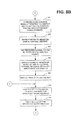
- FIG. 9 displays the self-test routine 400, in accordance with the method of the preferred embodiment of the present invention, which includes steps that the CPU 60 performs when the alert device 20 calls the self-test routine 400 at step 214 of the main portion 210 of the computer software program 200.
- the CPU 60 communicates, at step 404, an instruction to the peripheral device controller 70, via bus 74, directing the peripheral device controller 70 to display the words "SELF-TEST IN PROGRESS" on the liquid crystal display 36a.
- the peripheral device controller 70 then communicates appropriate signals to the liquid crystal display 36a through signal lines 98.
- the liquid crystal display 36a displays the words "SELF-TEST IN PROGRESS".
- the CPU 60 communicates instructions to the peripheral device controller 70 through bus 74 which direct the peripheral device controller 70 to generate appropriate signals on signal lines 100, 104 which, respectively, cause the high-level audio speaker 36b to produce a high-decibel level tone and the high-intensity strobe light 36d to periodically flash.
- the CPU 60 After delaying for the period of time stored in the self-test time period 81 of the non-volatile data memory 66 at step 410, the CPU 60 communicates commands, at steps 412 and 414, to the peripheral device controller 70 directing the peripheral device controller 70 to terminate the production of appropriate signals on respective signal lines 100, 104 and, hence, stop the high-level audio speaker 36b from generating a high-decibel level tone and the high-intensity strobe light 36d from flashing.
- the CPU 60 directs the peripheral device controller 70, by the communication of a command therebetween over bus 74, to initiate the production of a low-decibel level tone on the low-level audio speaker 36c.
- the peripheral device controller 70 generates appropriate signals on signal lines 102 which cause the low-level audio speaker 36c to begin producing a low-decibel tone.
- the CPU 60 sends an instruction to the peripheral device controller 70, via bus 74, instructing the peripheral device controller 70 to begin flashing of the low-intensity light-emitting diode 36e.
- the peripheral device controller 70 in response, generates appropriate signals on signal lines 106 which cause the low-intensity light-emitting diode 36e to flash periodically.
- the CPU 60 Upon delaying, at step 422 for a period of time equaling the self-test timer period 81 stored in non-volatile data memory 66, the CPU 60 communicates commands to the peripheral device controller 70 over bus 74, at steps 424 and 426, which direct the peripheral device controller 70 to stop the production of the low-decibel level tone and flashing light. Responsive to the commands, the peripheral device controller 70 terminates the production of signals on respective signal lines 102, 106, thereby stopping the generation of the low-decibel level tone from the low-level audio speaker 36c and the flashing of the low-intensity light-emitting diode 36e.
- the CPU 60 transmits an instruction over bus 74 to the peripheral device controller 70 directing the peripheral device controller 70 to cause the display of the words "SELF-TEST SUCCESSFULLY COMPLETED” on the liquid crystal display 36a.
- the peripheral device controller 70 then generates appropriate signals on signal lines 98, including signals representing the words "SELF-TEST SUCCESSFULLY COMLETED", to cause those words to appear on the liquid crystal display 36a.
- the liquid crystal display 36a displays the words "SELF-TEST SUCCESSULLY COMPLETED".
- the CPU 60 delays, at step 430, for a period of time corresponding to the self test time period 81 stored in the non-volatile data memory 66 before returning, at step 432, to the execution in accordance with the main portion 2 1 0 of the computer software program 200.
- FIG. 10 displays the high-level alarm routine 500, in accordance with the method of the preferred embodiment of the present invention, which includes steps that the CPU 60 performs when the alert device 20 calls the high-level alarm routine 500 at steps 262 and 270 of the main portion 210 of the computer software program 200.
- the CPU 60 communicates a command, at step 504 and via bus 74, to the peripheral device controller 70 instructing the peripheral device controller 70 to start producing a high-decibel level tone on the high-level audio speaker 36b,
- the peripheral device controller 70 generates and supplies, through signal lines 100, appropriate signals to the high-level audio speaker 36b, thereby causing the high-level audio speaker 36b to produce a continuous high-decibel level tone.
- the peripheral device controller 70 causes the high-level audio speaker 36b to produce non-continuous, high-decibel level tones.
- the CPU 60 similarly communicates a command, via bus 74, to the peripheral device controller 70 instructing the peripheral device controller 70 to start flashing the high-intensity strobe light 36d.
- the peripheral device controller 70 in response, produces and supplies appropriate signals, via signal lines 104, to the high-intensity strobe light 36d, thereby causing the high-intensity strobe light 36d to flash at a periodic rate.
- the peripheral device controller 70 causes the high-intensity strobe light 36d to flash in a non-periodic manner.
- the CPU 60 extracts the text message string 142 from the alert message 130 and communicates the extracted text message string 142 (and a command to display the extracted text message string 142) to the peripheral device controller 70 via bus 74.
- the peripheral device controller 70 then communicates appropriate signals, including the extracted text message string 142, to the liquid crystal display 36a through signal lines 98 in order to cause the extracted text message string 142 to appear on the liquid crystal display 36a.
- the CPU 60 Upon display of the extracted text message string 142 on the liquid crystal display 36a, the CPU 60 sets, at step 510, the count-down timer 72 by sending appropriate instructions to the count-down timer 72 via bus 74, to begin counting down for, according to the preferred embodiments, a period of two (2) hours during which the extracted text message string 142 remains displayed on the liquid crystal display 36a. Then, at step 512, the CPU 60 resumes execution in accordance with the main portion 210 of the computer software program 200 after the step which called for execution of the steps of the high-level alarm routine 500.
- FIG. 11 displays the low-level alarm routine 600, in accordance with the method of the preferred embodiment of the present invention, which include steps that the CPU 60 perform when the alert device 20 calls the low-level alarm routine 600 at steps 266 and 274 of the main portion 210 of the computer software program 200.
- the CPU 60 communicates a command, at step 604 and via bus 74, to the peripheral device controller 70 instructing the peripheral device controller 70 to start producing a low-decibel "chirping" tone on the low-level audio speaker 36c.
- the peripheral device controller 70 generates and supplies, through signal lines 102, appropriate signals to the low-level audio speaker 36c, thereby causing the low-level audio speaker 36c to produce a "chirping" low-decibel level tone.
- the peripheral device controller 70 causes the low-level audio speaker 36c to produce continuous, low-decibel level tone.
- the CPU 60 similarly communicates a command, via bus 74, to the peripheral device controller 70 instructing the peripheral device controller 70 to start flashing the low-intensity light-emitting diode 36e.
- the peripheral device controller 70 in response, produces and supplies appropriate signals, via signal lines 106, to the low-intensity light-emitting diode 36e, thereby causing the low-intensity light-emitting diode 36e to flash at a periodic rate.
- the peripheral device controller 70 causes the low-intensity light-emitting diode 36e to flash in a non-periodic manner.
- the CPU 60 extracts the text message string 142 from the alert message 130 and communicates the extracted text message string 142 (and a command to display the extracted text message string 142) to the peripheral device controller 70 via bus 74.
- the peripheral device controller 70 then conmunicates appropriate signals, including the extracted text message string 142, to the liquid crystal display 36a through signal lines 98 in order to cause the extracted text message string 142 to appear on the liquid crystal display 36a.
- the CPU 60 Upon display of the extracted text message string 142 on the liquid crystal display 36a, the CPU 60 sets, at step 610, the count-down timer 72 by sending appropriate instructions to the count-down timer 72 via bus 74, to begin counting down for, according to the preferred embodiments, a period of two (2) hours during which the extracted text message string 142 remains displayed on the liquid crystal display 36a. Then, at step 612, the CPU 60 resumes execution in accordance with the main portion 210 of the computer software program 200 after the step which called for execution of the steps of the low-level alarm routine 600.
- FIG. 12 displays the timer interrupt handling routine 700, in accordance with the method of the preferred embodiment of the present invention, which includes steps that the CPU 60 performs when the count-down timer 72 completes counting down to zero and provides an asynchronous interrupt signal to the CPU 60 via bus 74.
- the CPU 60 communicates a command, at step 704 and via bus 74, to the peripheral device controller 70 instructing the peripheral device controller 70 to clear the liquid crystal display 36a and then display the word "READY" on the liquid crystal display 36a.
- the peripheral device controller 70 then communicates appropriate signals, including the word "READY", to the liquid crystal display 36a through signal lines 98 in order to cause erasure of all text present on the liquid crystal display 36a and to cause the word "READY" to appear on the liquid crystal display 36a.
- the liquid crystal display 36a erases all text and then displays the word "READY”.
- the CPU 60 at step 706, resumes execution in accordance with the main portion 210 of the computer software program 200.
- FIG. 13 displays the reset interrupt handling routine 800, in accordance with the method of the preferred embodiment of the present invention, which includes steps that the CPU 60 performs when the reset pushbutton 36f is depressed by a user (i.e., to stop the generation of all sounds and all flashing light) and the peripheral device controller 70, in response, provides an asynchronous interrupt signal to the CPU 60 via bus 74.
- the CPU 60 communicates, at step 804, a command to the peripheral device controller 70, via bus 74, instructing the peripheral device controller 70 to stop the production of all tones from all audio speakers 36b, 36c.
- the peripheral device controller 70 ceases the generation and supply of signals on signal lines 100, 102 in order to terminate the production of tones from the high-level audio speaker 36b and the low-level audio speaker 36c. Then, at step 806, the CPU 60 communicates a command to the peripheral device controller 70, via bus 74, instructing the peripheral device controller 70 to stop the flashing of the high-intensity strobe light 36d and the low-intensity light-emitting diode 36c. The peripheral device controller 70, in response, ceases the generation and supply of signals on signal lines 104, 106, thereby stopping the flashing of the high-intensity strobe light 36d and the low-intensity light-emitting diode 36e. After stopping the generation of all flashing light, the CPU 60, at step 808, resumes execution in accordance with the main portion 210 of the computer software program 200.
- PCS refers to any short-range, geographically-distributed broadcast system similar to those commonly used in cellular or PCS mobile telecommunication networks and the like. It is also understood that the scope of the present invention includes alert devices which operate with other digital wireless telecommunication networks and which receive broadcast messages which are formatted and transmitted using formats, protocols, geographical identifiers, and severity indicators other than that defined by the Broadcast Short Messages System or by the EAS AM & FM Handbook.
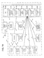
- FIG. 14 displays an alert device 20', in accordance with an apparatus of an alternate preferred embodiment of the present invention, for use at installations where audible tones and flashing light must be delivered to persons located remotely from the site of the alert device 20'.
- the alert device 20' is substantially similar to the alert device 20 of the preferred embodiment, except that the alert device 20' further comprises an external peripheral interface 75' which connects to the peripheral device controller 70' and to pluralities of remote peripheral devices 37a', 37b', 37c' (see FIG. 15 ).
- Each plurality of remote peripheral devices 37' comprises a remotely-located liquid crystal display 36aa', a remotely-located high-level audio speaker 36bb', a remotely-located low-level audio speaker 36cc', a remotely-located high-intensity strobe light 36dd', a remotely-located low-intensity light-emitting diode 36ee', and a remotely-located reset pushbutton 36ff' which connect to the external peripheral interface 75' via respective signal lines 99', 101', 103', 105', 107', 111'.
- the apparatus of the alternate preferred embodiment operates in accordance with a method of the alternate preferred embodiment which is substantially similar to the method of the preferred embodiment, except that when tones, flashing light and textual displays are produced by the plurality of peripheral devices 36' located within or protruding from the enclosure 22' of the alert device 20', tones, flashing light and textual displays are also simultaneously produced from all of the peripheral devices of the pluralities of remote peripheral devices 37a', 37b', 37c' in response to signals produced on signal lines 109' by the peripheral device controller 70' and communicated by the external peripheral interface 75' to the pluralities of remote peripheral devices 37a', 37b', 37c'.
- termination of the tones, flashing light and display of textual information produced by the plurality of peripheral devices 36' located within or protruding from the enclosure 22' of the alert device 20' occurs, termination of the tones, flashing light and display of textual information simultaneously occurs with respect to the pluralities of remote peripheral devices 37a', 37b', 37c' in response to signals produced on signal lines 109' by the peripheral device controller 70' and communicated by the external peripheral interface 75 to use the pluralities of remote peripheral devices 37a', 37b', 37c'.
- the invention also provides an apparatus for providing to a user location-specific alert information associated with an alert condition relevant to persons in the selected geographical area of the user, the location-specific alert information being broadcast to the selected geographical area by at least one transmitter of a wireless bi-directional communication network having a plurality of communication channels and a plurality of transmitters which are each positioned to provide communication services to persons in a particular respective geographical area serviced by the communication network, said apparatus comprising: a receiver adapted to receive transmissions on a communication channel of the plurality of communication channels of the wireless bi-directional communication network; a peripheral device operable to inform the user of the existence of a relevant alert condition; and, a controller communicatively connected to said receiver and said peripheral device, said controller being operable to continuously monitor a communication channel of the wireless bi-directional communication network solely for the receipt of the transmission of location-specific alert information from a transmitter servicing the selected geographical area of the user and to operate said peripheral device in response to the reception of a transmission of location-specific alert information.
- the invention also provides a method of operating a device having a receiver and a peripheral device to receive location-specific alert information pertaining to an alert condition which is broadcast by a wireless bi-directional communication network having a plurality of communication channels and to inform a user of the existence of the alert condition, the method comprising the steps of: selecting a communication channel from the plurality of communication channels of the wireless bi-directional communication network; monitoring the selected communication channel with the receiver for a transmission including location-specific alert information pertaining to the alert condition; and, operating the peripheral device to notify the user of the alert condition upon detection of a transmission including location-specific alert information.
- the invention also provides a apparatus for providing to a user location-specific alert information associated with an alert condition relevant to persons in the selected geographical area of the user, the location-specific alert information being digitally broadcast to the selected geographical area by at least one transmitter of a wireless bi-directional telecommunication network, the location-specific alert information including information rendering the location-specific alert information identifiable from other transmissions of the communication network, said apparatus comprising; a receiver adapted to receive digital transmissions on a channel of the plurality of communication channels of the wireless bi-directional communication network; a peripheral device operable to inform the user of the existence of the alert condition; and, a controller communicatively connected to said receiver and said peripheral device, said controller being operable to recognize the information rendering the location-specific alert information identifiable from other transmissions of the communication network and to operate said peripheral device in response to the recognition of a digital transmission of location-specific alert information.
Abstract
Description
- This invention relates generally to the field of alert systems and, in its preferred embodiments, to alert systems utilizing cellular, personal communication system, or wireless telecommunication technology to deliver an alert to a person.
- In recent decades, the science of meteorology has advanced rapidly, allowing increasingly accurate detection and prediction of severe and hazardous weather. Specifically, Doppler radar systems and high resolution satellites have been developed which allow early detection of tornadoes and severe thunderstorms and accurate tracking of their paths. The National Weather Service (NWS) and National Oceanographic and Atmospheric Administration (NOAA) now routinely issue warnings in advance of most severe or tornadic storms, alerting individuals and saving lives. However, in order for these warnings, or "alerts" to be effective, they must be communicated to and received by their intended recipients.
- Some local governments and municipalities utilize civil defense siren systems to provide warnings to persons within the localized range of the siren systems in case of severe weather, natural disaster, war or other emergency conditions. However, weather-related warnings are more commonly provided through the NOAA Weather Radio system which is a nationwide network of radio stations operating twenty-four (24) hours per day to broadcast continuous weather information directly from the local offices of the National Weather Service. The NOAA Weather Radio system also broadcasts alerts for the Emergency Alert System (EAS), maintained by the Federal Communication Commission, in order to provide emergency warnings for all types of hazards, including, but not limited to, earthquakes, volcano erruptions, severe weather and nuclear war. The NOAA Weather Radio system has more than 450 transmitters, covering broad areas in each of the 50 states, adjacent coastal waters, Puerto Rico, the U.S. Virgin Islands, and the U.S. Pacific Territories. Unfortunately, reception of the Emergency Alert System warnings via the NOAA, Weather Radio system generally requires a special radio receiver or scanner capable of picking up its emergency warning signals.
- Tone-activated alert receivers are commonly used to monitor NOAA Weather Radio broadcasts, to provide warning of severe weather and to provide emergency and civil defense alerts. A tone-activated alert receiver constantly monitors the local NOAA Weather Radio broadcasts for a specific 1050 Hz emergency alert tone. In response to receiving an emergency alert tone, a tone-activated alert receiver produces an audible and/or visual alarm, and activates a radio tuned to the NOAA Weather Radio broadcast. Since each NOAA Weather Radio station transmits its signals to a relatively large geographical area, older tone-activated alert receivers suffer from the disadvantage of falsely responding to alerts when the condition to which the emergency alert pertains is only relevant to other geographical areas in the broadcast area of the particular NOAA Weather Radio station transmitting the alert tone.
- Newer NOAA Weather Radio receivers, known as "SAME receivers", incorporate a feature known as Specific Area Message Encoding (SAME) to decrease the frequency of false alerts. A SAME receiver recognizes a specific digital location code, in an emergency broadcast signal, which designates a specific locality for which alerts are relevant. Once programmed by a user to respond only to a specific digital location code for the area of the user, a SAME receiver switches into alarm mode only upon receipt of an emergency broadcast signal which includes a SAME digital location code matching the preprogrammed digital code. Accordingly, SAME receivers are generally deployed in a particular, fixed location such as an individual's home or office. While these SAME receivers are useful in their fixed locations, they are not particularly useful if moved from the location for which they have been programmed. Additionally, like many individuals who cannot program a video cassette recorder (VCR), some individuals may find it difficult or inconvenient to program the SAME receiver.
- As an alternative to SAME receivers, some persons are proposing that cellular or Personal Communication System (PCS) wireless telephone networks be employed to deliver emergency alerts to individuals having cellular or PCS wireless telephones because cellular and PCS telephone networks typically employ short-range, broadcast transceivers (or transmitters) which have coverage areas, or cells, of a reasonably small size, thereby enabling the delivery of emergency alerts to persons in selected areas served by particular broadcast transmitters. As proposed, delivery of emergency alert messages to selected local areas would be achieved by activating only those cellular or PCS broadcast transceivers providing coverage for the specific geographical area to which the emergency alert is relevant, instead of requiring the transmission, preprogramming, and recognition of a specific digital location code corresponding to the geographical area for which the emergency alert is relevant. However, until recently, wireless telephone networks have not had the capability of transmitting alphanumeric messages that would be required to effectively distribute emergency alert messages. In contrast, conventional paging systems have the capability of supporting alphanumeric messaging, but have coverage areas far to large to provide the level of geographical specificity required to deliver location specific, emergency alert messages.
- New cellular and PCS telephone networks are currently being deployed, or have been deployed, throughout North America and Europe which are capable of transmitting alphanumeric messages and which have coverage areas providing sufficient geographical specificity to make them ideal vehicles for the delivery of location-specific, emergency alert messages. Using the newer cellular and PCS networks, a network operator can send messages to a cellular or PCS telephone present in any single cell or any group of cells serviced by the transceivers of the network. Accordingly, some persons have recently proposed that these cellular and PCS networks be used to transmit location-specific, emergency alert messages to the cellular or PCS telephone handsets of individual users by dialing the telephone number associated with each handset and, upon answer by the cellular or PCS handset, delivering the emergency alert message to the handset.
- While cellular or PCS telecommunications systems may be an effective vehicle for conveying location-specific, emergency alert messages, such systems enable delivery of emergency alert messages to only those individuals who can figure out how get such messages via their wireless telephones. Currently, to get such messages, individuals must find their way through a myriad of icons (which many individuals cannot do) and then review all of their messages in order to identify the emergency alert messages from other messages. Further, the delivery of emergency alert messages via cellular or PCS telecommunications systems requires individuals to have their handsets nearby and turned-on (and not depleted of battery power). Unfortunately, individuals often turn-off their handsets, forget to recharge them, or leave their handsets, for instance, in the car while they are at home or work. As a result, a system which relies upon cellular or PCS handset receivers to receive emergency alert messages may fail to notify a large number of individuals of the existence of an emergency condition.
- Other similar difficulties are inherent in the delivery of information or messages which relate to military or other operations (i.e., a different type of "alert"). For instance, if a branch of the military needs to inform its reservists to report for duty on Sunday instead of Saturday as the reservists were originally notified, it typically contacts each reservist individually by telephone to provide the reservist with such information, thereby requiring a substantial use of labor to perform such a task.
- Therefore, there is a need in the industry for an apparatus and method whereby individuals may reliably receive cellular or PCS transmissions of location-specific alert information without requiring the use of a cellular or PCS telephone handset. Furthermore, there is a need for an apparatus and method whereby individuals may reliably receive cellular or PCS transmissions of location-specific alert information without requiring individuals to perform complex retrieval steps or inconvenient receiver programming steps.
- Briefly described, the present invention comprises an alert apparatus and method for receiving a location-specific alert (i.e., an alert directed and relevant to a particular geographical area) and for informing a user, who may be visually or hearing impaired, of the existence and severity of the alert. More particularly, the present invention includes an alert apparatus and method which allow a user to receive data corresponding to an alert which has been broadcast via particular transmitters operating within a cellular, PCS, or wireless telephone communications network, thereby allowing receipt of a location-specific alert (and a textual message associated with the alert) without requiring the user to input, to the alert apparatus, data representative of or identifying the location of the apparatus. Further, the present invention includes an alert apparatus and method which produces high-decibel level audible sounds and high-intensity flashing strobe light corresponding to alerts of the most severe level and which produces low-decibel level audible sounds and low-intensity flashing light from a light-emitting diode corresponding to alerts of a less severe level.
- In accordance with the preferred embodiment, the apparatus of the present invention comprises an alert device having a microcomputer which directs operation of the alert device according to the instructions of a computer software program stored therein. The alert device also includes a receiver which receives digital PCS transmissions broadcast over a PCS or cellular telecommunication network. The microcomputer has a central processing unit and a monitoring circuit communicatively connected to the central processing unit and receiver. The monitoring circuit is capable of setting the receiver to receive transmissions, if any, on radio channels identified by the central processing unit, of determining the signal strength associated with transmissions received on such radio channels, of identifying the presence of a digital control channel on a radio channel, and of communicating signal strength information, digital control channel information, and broadcast short messages, received by the receiver, to the central processing unit
- According to the preferred embodiment of the present invention, the alert device further comprises a plurality of peripheral devices and the microcomputer further comprises a peripheral device controller which connects to the plurality of peripheral devices. The plurality of peripheral devices includes a liquid crystal display, a high-level audio speaker, a low-level audio speaker, a high-intensity strobe light, and a low-intensity light-emitting diode. The microcomputer, via the peripheral device controller, controls the operation of the plurality of peripheral devices according to the severity of a condition identified by an alert. For instance, the microcomputer causes the production of audible sound from the high-level audio speaker at a high-decibel level and flashing of the high-intensity strobe light to warn a user of the existence of a "Level One" alert (i.e., the most severe or important alert condition). Similarly, the microcomputer causes the production of audible sound from the low-level audio speaker at a low-decibel level and flashing of the low-intensity light-emitting diode to warn a user of the existence of a "Level Two" alert (i.e., a less severe or less important alert condition). The microprocessor, via the peripheral device controller, also causes the display, on the liquid crystal display, of textual information, received as part of an alert message.
- The alert device, in accordance with the preferred embodiment, is operable to continuously monitor broadcasts from a cellular, PCS, or wireless telecommunications network. Accordingly, the alert device connects to an electrical outlet to receive electrical power for normal operation, but includes a battery backup and charging circuit to ensure operation of the alert device even in the event of a power failure. Furthermore, in the referred embodiment, the alert device operates continuously when supplied with electrical power, has no on/off switch, and thus cannot easily be deactivated by a user unlike a cellular or PCS telephone handset. The alert device does, however, include a reset pushbutton which enables a user to temporarily deactivate, or stop, the audible and visual alarms once notified of an alert condition. In the preferred embodiment, the alert device is mountable to an electrical wall socket in a manner substantially similar to that of a conventional smoke detector. In an alternate embodiment, the alert device has an enclosure which enables the device to reside atop a table or other surface in a manner substantially similar to that of a weather radio. In an alternate preferred embodiment, the alert device includes a plurality of peripheral devices which are locatable at sites remote from the alert device.
- In accordance with a method of the preferred embodiment of the present invention, the alert device operates according to the instructions of a computer software program residing in the microcomputer and performs a self-test when powered-up to determine whether the alert device is functioning properly. The alert device, thorough cooperation between the microcomputer, monitoring circuit, and receiver, then scans a factory-set, pre-identified set of radio channels comprising a range of charnels used by compatible cellular or PCS telecommunication networks in order to identify the channel associated with the cellular or PCS transmitter which transmits on a digital control channel and which has the strongest signal strength at the location of the alert device. The alert device then locks onto and passively monitors the selected channel for digital alerts in the form of broadcast short messages. Because the alert device passively monitors PCS network broadcasts, use of the alert device should not result in the user incurring periodic service charges from the network provider.
- According to the method of the present invention, the alert device, upon detecting and receiving a broadcast short message, identifies whether the broadcast short message comprises an alert message. If so, the alert device then analyzes the alert message and determines the severity level of the alert identified by the alert message. If the alert is a "Level One" alert, the alert device operates, as described above, the high-level audio speaker to produce a highly obtrusive, high-decibel level sound substantially similar to that of a conventional smoke detector (i.e., a sound that would cause even the hardest of sleepers to awaken) and the high-intensity strobe light to produce flashing, high-intensity, bright light. If the alert is a "Level Two" alert, the alert device operates, as described above, the low-level audio speaker to produce a less-obtrusive, low-decibel level, "chirping" sound and the low-intensity liglit-emitting diode to produce less-intense, less-bright" flashing light. Regardless of the severity level of the alert, the alert device extracts textual message information, if any, from the alert message and displays the textual message information on the liquid crystal display to provide a user with a more detailed explanation as to the nature of the alert. Once the user is informed as to the existence and nature of the alert, the production of audible sounds and the generation of flashing light is terminable by the user through depression of the reset pushbutton protruding partially from the alert device.
- Accordingly, it is an object of the present invention to provide an apparatus and method for receiving location-specific alert information without requiring a user to input data representative of the user's location.
- Another object of the present invention is to provide an apparatus and method for receiving location-specific alert information which is not limited to a fixed location.
- Still another object of the present invention is to provide an apparatus for receiving location-specific alert information which can be moved from an old location to a new location without requiring reprogramming or the input of data representative of the new location.
- Still another object of the present invention is to provide an apparatus for receiving location-specific alert information which self-identifies the strongest source of such alert information.
- Still another object of the present invention is to provide an apparatus for receiving location-specific alert information which self-identifies the frequency on which the alert information is transmitted or broadcast.
- Still another object of the present invention is to provide an apparatus and method for receiving location-specific alert information which identifies the different levels of severity associated with alerts.
- Still another object of the present invention is to provide an apparatus and method for receiving location-specific alert information which produces different sensory outputs corresponding to the different levels of severity or importance of alerts.
- Still another object of the present invention is to provide an apparatus and method for receiving location-specific alert information which operates continuously, unless moved by a user, at a particular location.
- Still another object of the present invention is to provide an apparatus and method for receiving location-specific alert information which is continuously operable from an external electrical power source and which has an internal battery backup for use during power failures.
- Still another object of the present invention is to provide an apparatus and method for receiving location-specific alert information which displays a textual message related to the alert for which the alert information pertains.
- Other objects, features and advantages of the present invention will become apparent upon reading and understanding the present specification when taken in conjunction with the appended drawings.
-
-
FIG. 1 is a pictorial representation of an alert device in accordance with a preferred embodiment of the present invention. -
FIG. 2 is a block diagram representation of the alert device ofFIG. 1 displaying the major components thereof -
FIG. 3 is a schematic representation of the program domain of the non-volatile program memory of the alert device ofFIG. 1 . -
FIG. 4 is a schematic representation of the data domain of the non-volatile data memory of the alert device ofFIG. 1 . -
FIG. 5 is a schematic representation of the data domain of the volatile data memory of the alert device ofFIG. 1 . -
FIG. 6 is a pictorial representation of an exemplary PCS alert broadcast system in accordance with a preferred embodiment of the present invention. -
FIG. 7 is a schematic representation of the data of a digital alert message in accordance with a preferred embodiment of the present invention. -
FIG. 8 is a flowchart representation of a main portion of a computer software program of the alert device in accordance with a method of the preferred embodiment of the present invention. -
FIG. 9 is a flowchart representation of a self-test routine of the computer software program of the alert device in accordance with a method of the preferred embodiment of the present invention. -
FIG. 10 is a flowchart representation of a high-level alarm routine of the computer software program of the alert device in accordance with a method of the preferred embodiment of the present invention. -
FIG. 11 is a flowchart representation of a low-level alarm routine of the computer software program of the alert device in accordance with a method of the preferred embodiment of the present invention. -
FIG. 12 is a flowchart representation of a timer interrupt handling routine of the computer software program of the alert device in accordance with a method of the preferred embodiment of the present invention. -
FIG. 13 is a flowchart representation of a reset interrupt handling routine of the computer software program of the alert device in accordance with a method of the preferred embodiment of the present invention. -
FIG. 14 is a block diagram representation of a first portion of an alert device of an alternate preferred embodiment displaying the major components thereof. -
FIG. 15 is a block diagram representation of the first portion of the alert device ofFIG. 14 and a plurality of remotely-located peripheral devices of a second portion of the alert device. - Referring now to the drawings, in which like numerals represent like components throughout the several views, an
alert device 20, in accordance with an apparatus of the preferred embodiment of the present invention, is shown in pictorial form inFIG. 1 and in block diagram form inFIG. 2 . Thealert device 20 comprises anenclosure 22 and amicrocomputer 24,receiver 26, diversity receiveantenna 28,power supply 30, andbackup battery 32 residing therein. Preferably, theenclosure 22 is manufactured from a durable plastic material and thealert device 20 is directly pluggable into an electrical wall outlet through use of anelectrical plug 34 located on the back of theenclosure 22, thereby avoiding the need for mounting hardware and the difficulties of mounting theenclosure 22 to a wall. According to the apparatus of the preferred embodiment, thereceiver 26 is adapted to receive digital signals within the ranges of channels utilized for cellular, PCS, or other wireless communications in the area in which thealert device 20 is deployed. For example and not limitation, thereceiver 26 is adapted to receive digital signals on channels having receive-side frequencies in the (i) 969 MHz to 994 MHz range, (ii) 1840 MHz to 1865 MHz range, (iii) 1930.72 MHz to 1945 MHz range, (iv) 1950.72 MHz to 1965 MHz range, or (v) 1975.72 MHz to 1990 MHz range. It is understood, however, that the scope of the present invention includes similar receivers which are adapted to receive cellular, PCS, or wireless digital signals in any frequency range. - The
alert device 20 further comprises a plurality of peripheral devices 36 which electrically connect to themicrocomputer 24, and anexternal antenna 38 having a first portion which resides within theenclosure 22 and a second portion which extends outside of theenclosure 22. Anexternal antenna 38, acceptable in accordance with the preferred embodiment, is a rubber-covered antenna commonly known as a "rubber duck antenna" which is often found in cellular PCS, or wireless telephones. - The plurality of peripheral devices 36 includes a
liquid crystal display 36a residing within theenclosure 22 adjacent to anopening 40 in theenclosure 22 which enables theliquid crystal display 36a to be visible from outside theenclosure 22. Preferably, theliquid crystal display 36a is backlit to enhance the readability of thedisplay 36a. Theliquid crystal display 36a hassignal strength indicator 37 located near the right side of thedisplay 36a. Thesignal strength indicator 37 comprises a plurality of liquid crystal bars 39 arranged in a, generally, vertical direction which themicrocomputer 24 energizes to darken the bars 39 and, thereby indicate the signal strength of the strongest channel received by thealert device 20 at the device's then-existing location. A stronger signal strength is indicated by energization and darkening of a larger number of bars 39, while a weaker signal is indicated by energization and darkening of a smaller number of bars 39. - The plurality of peripheral devices 36 also includes a high-
level audio speaker 36b and a low-level audio speaker 36c which reside within theenclosure 22 at positions adjacent respective grill-like openings enclosure 22 that allow audible sounds generated by thespeakers enclosure 22 to the environment surrounding theemergency alert device 20. In accordance with the preferred embodiment, the high-level audio speaker 36b includes a speaker, substantially similar to those found in smoke detectors, which produces a high-decibel level continuous or pulsating tone that is sufficiently loud to awaken a sleeping person. The low-level audio speaker 36c, according to the preferred embodiment, includes a speaker which, when appropriately activated, emits a periodic "chirp-type" sound substantially similar to the sound emitted by the speakers employed in portable pagers. - The plurality of peripheral devices 36 additionally includes a high-
intensity strobe light 36d and a low-intensity light emitting diode (LED) 36e which reside within theenclosure 22 and are visible, through a window-coveredopening 46, from outside theenclosure 22. The high-intensity strobe light 36d, in accordance with the apparatus of the preferred embodiment, includes a conventional xenon flash tube which is pulsable in a periodic manner to produce a bright flash of light every one to two seconds when in use, thereby enabling thealert device 20 to draw the attention of a bearing impaired person. The low-intensitylight emitting diode 36e, according to the apparatus of the preferred embodiment, includes a conventional, red light emitting diode which is pulsable in a manner similar to that employed with the high-intensity strobe light 36d. The plurality of peripheral devices 36 further includes areset pushbutton 36f which extends through an opening in theenclosure 22 so as to be depressable by a user of thealert device 20. - The
microcomputer 24 comprises, preferably, a custom-manufactured device substantially similar to those microcomputers residing in cellular, PCS, or wireless telephones and includes, integrated therein, a central processing unit (CPU) 60, amonitoring circuit 62, anon-volatile program memory 64, anon-volatile data memory 66, avolatile data memory 68, aperipheral device controller 70, and a count-down timer 72. Thenon-volatile program memory 64, illustrated inFIG. 3 , stores acomputer software program 200 having amain portion 210, a self-test routine 400, a high-level alarm routine 500, a low-level alarm routine 600, a timer interrupt handling routine 700, and a reset interrupt handling routine 800 which theCPU 60 executes, as described below, to cause thealert device 20 to operate in accordance with a method of the preferred embodiment of the present invention. - The
non-volatile data memory 66, illustrated inFIG. 4 , stores values for the startingchannel identifier 76 and the endingchannel identifier 78 of the range of channels to be monitored, or scanned, by thereceiver 26 for the presence of a digital control channel as described below. Thenon-volatile data memory 66 also stores the value of the test channel step-size 80 and a plurality of receivefrequencies 82 corresponding in a one-to-one relationship with channels to be possibly monitored by the receiver 26 (i.e., so that receivefrequency 82a corresponds to the first channel possible for monitoring, receivefrequency 82b corresponds to the second channel possible for monitoring, and receive frequency 82n corresponds to the nth channel possible for monitoring. In accordance with the preferred embodiment, thenon-volatile data memory 66 stores a plurality of receivefrequencies 82 corresponding to the channels associated with the receive-side frequencies in (i) the 969 MHz to 994 MHz range, (ii) the 1840 MHz to 1865 MHz range, (iii) the 1930.72 MHz to 1945 MHz range, (iv) the 1950.72 MHz to 1965 MHz range, or (v) the 1975.72 MHz to 1990 MHz range. Thenon-volatile data memory 66 also stores a self-test time period 81 which defines the amount of time that the self-test routine 400 delays at various steps during execution. - The
volatile data memory 68, illustrated inFIG. 4 , stores a plurality of channel identifers 84 and a plurality of signal strength values 86 organized in a list, or table, 88 of plurality of channel identifier/signal strength pairs 90. Each channel identifier/signal strength pair 90 comprises a channel identifier 84 and a respective signal strength value 86 which represent a number identifying a digital control channel found and the associated signal strength value 86 (also referred to herein as "signal strength") identified by thereceiver 26 andmonitoring circuit 62 as described below. Thevolatile data memory 66 also stores atest channel identifier 91 and apointer 93 to the digital control channel selected as described below (also referred to herein as a "alert channel pointer 93"). - According to the preferred embodiment of the present invention, the
peripheral device controller 70 is an intelligent controller which produces, at appropriate times described below, signals necessary to cause operation of each peripheral device 36 of the plurality of peripheral devices 36 as described herein. For example and not limitation, theperipheral device controller 70 produces, when necessary, signals necessary to cause the high-level audio speaker 36b to generate an obtrusive tone which should wake the soundest of sleepers, the low-level audio speaker 36c to generate "chirping" sounds, and the bigh-intensity strobe light 36d and the low-intensity light-emittingdiode 36e to flash. Theperipheral device controller 70 also ceases, at appropriate times described below, the production of signals which cause operation, for instance, of the high-level audio speaker 36b, the low-level speaker 36c, the high-intensity strobe light 36d, and the low-intensity light-emittingdiode 36e. - The count-
down timer 72, according to the preferred embodiment, comprises a timer which is programmable by theCPU 60 to start counting down time from an initial time provided to the count-down timer 72 by theCPU 60. Upon reaching zero, the count-down timer 72 produces an interrupt signal which is communicated to theCPU 60. Thereset pushbutton 36f also produces an interrupt signal which is communicated to theCPU 60. - The
microcomputer 24, as displayed inFIG. 2 , further includes abus 74 which interconnects theCPU 60 and themonitoring circuit 62,non-volatile program memory 64,non-volatile data memory 66,volatile data memory 68,peripheral device controller 70, and count-down timer 72 for the communication of address, data, and control signals (including interrupt signals) therebetween. Themonitoring circuit 62 communicatively connects to thereceiver 26 through signal lines 92.Receiver 26 electrically connects, viarespective signal lines antenna 28 and theexternal antenna 38. Theperipheral device controller 70 communicatively connects to theliquid crystal display 36a, the high-level audio speaker 36b, the low-level audio speaker 36c, the high-intensity strobe light 36d, the low-intensity light emitting diode (LED) 36e, and thereset pushbutton 36f throughrespective signal lines - The
power supply 30 connects, viaelectrical conductors 110, toelectrical plug 34 for the receipt of alternating-current electrical power. Thepower supply 30 converts the alternating-current electrical power into direct-current electrical power at appropriate voltages. Thepower supply 30 also connects to themicrocomputer 24, thereceiver 26, and the plurality of peripheral devices 36, where necessary (although not shown inFIG. 2 ), for the delivery of direct-current electrical power thereto at appropriate voltages. Thepower supply 30 includes a charging and switchingcircuit 112 therein which bi-directionally connects to thebackup battery 32 throughconductors 114. During operation, whenever alternating-current electrical power is supplied to thealert device 20, the charging and switchingcircuit 112 charges thebackup battery 32, if necessary, by delivering direct-current electrical power to thebackup battery 32 throughconductors 114. Alternatively, whenever alternating-current electrical power is not supplied to the alert device 20 (for example, due to a utility or other power failure), thebackup battery 32 supplies direct-current electrical power to the charging and switchingcircuit 112 throughconductors 114 for subsequent delivery to themicrocomputer 24, thereceiver 26, and the plurality of peripheral devices 36, where necessary. - In accordance with the apparatus of the preferred embodiment of the present invention, the
receiver 26 further includes those receivers capable of receiving digital cellular, PCS, or wireless telecommunication signals corresponding to alert messages 130 (described below) broadcast from cellular, PCS, or wireless telecommunication transmitters 120 residing on towers 122 that are positioned to provide cellular, PCS, or wireless telecommunications services for respective, localized, and identifiable geographical areas 124 as illustrated pictorially inFIG. 6 . Thealert messages 130 are produced, prior to their reception by areceiver 26, by an alert messaging system. An alert messaging system is, typically, operated by a governmental authority and comprises telecommumications equipment, computer hardware and computer software which: (i) receives an alert from a source, for instance, the Emergency Alert System or National Weather Service or Department of Defense, (ii) determines whether one or morealert messages 130 corresponding to the alert should be broadcast, (iii) identifies the appropriate telecommunications transmitters 120 (and, hence, the geographical areas 124) to which the alert message(s) 130 should be delivered, (iv) builds and formats the alert message(s) 130 appropriately, and (v) communicates the alert message(s) 130 to a cellular, PCS, or wireless telecommunications network for routing of the alert message(s) 130 to the identified telecommunications transmitter(s) 120 which, subsequently, broadcast the alert message(s) 130 to their respective geographical area(s) 124. - The
alert messages 130 received byreceiver 26 and acted upon, as described below, by thealert device 20 include, according to the preferred embodiment of the present invention,messages 130 which are encoded by the alert messaging system according to the Broadcast Short Messages System in the format of a PCS short message (illustrated by the schematic data representation ofFIG. 7 ). Eachalert message 130 includes amessage header 132 indicating that themessage 130 includes alert data and the general level of the alert. Preferably, theheader 132 comprises eight (8) bytes of data, including a three (3)byte market code 134, a two (2) byte zone code 136, a two (2) bytealert level code 138, and a one (1)byte date stamp 140. Themarket code 134 includes data which identifies the regional market for which thealert message 130 is intended (i.e., the regional market includes a plurality of telecommunication transmitters 120 located in the geographical region identified by the regional market code). The zone code 136 comprises data which identifies the particular telecommunication transmitter 120 within the regional market that is to broadcast thealert message 130. Together, themarket code 134 and the zone code 136 are used by the cellular, PCS, or wireless telecommunications network, as described above for routing and communication of thealert message 130 to the telecommunications transmitter(s) 120 and geographical area 124 identified as appropriate by the alert messaging system. - The
alert level code 138 of eachalert message 130 includes data which identifies the severity and type of the alert condition. The EAS AM & FM Handbook, published by the Federal Communication Commission of the United States divides the alerts sent out by the Emergency Alert System ("EAS") (referred to herein as "emergency alerts") into three (3) general levels of severity. A "Level Zero" emergency alert (i.e., signified by analert message 130 in which thealert level code 138 has a value of four (4)) indicates the existence of no emergency alert conditions and that previous emergency alerts are no longer valid or no longer in effect. A "Level One" alert (i.e., signified by analert message 130 in which thealert level code 138 has a value of five (5)) indicates the existence, in the geographical area 124.to which thealert message 130 pertains and is communicated, of an emergency situation posing an extraordinary threat to the safety of life or property such as, but not limited to, the existence, or imminent existence, of a tornado, flood, fire, discharge of hazardous materials, industrial explosion, or nuclear incident. A "Level Two" emergency alert (i.e., signified by analbert message 130 in which thealert level code 138 has a value of six (6)) indicates the issuance of a severe weather watch or that a particular emergency condition is possible in the geographical area 124 to which the emergency alert is communicated via telecommunication transmitters 120. - According to the preferred embodiments, the
alert level code 138, when appropriate, contains values other than those values described above to indicate other types of alerts and the respective seventy of such other types of alerts. For instance, a "Level One" military alert (i.e., signified by analert message 130 in which thealert level code 138 has a value of seven (7)) indicates the existence, for the geographical area 124 to which thealert message 130 pertains and is communicated, of an extremely important military alert (as an example, an alert requiring that all active duty military personnel and reservists report to their bases immediately). A "Level Two" military alert (i.e., signified by analert message 130 in which thealert level code 138 has a value of eight (8)) indicates the existence, for the geographical area 124 to which thealert message 130 pertains and is communicated, of a less-important military alert (as an example, an alert requesting that all reservists report on Sunday instead of Saturday). It is understood that the scope of the present invention includes other types and severities of alerts having different values foralert level code 138. - Each
alert message 130 further includes atext message string 142 which follows themessage header 132. Thetext message string 142, preferably, includes a maximum of 160 ASCII text characters for display on theliquid crystal display 36a of thealert device 20 and provides more detailed information or instructions related to an alert condition. Because eachalert message 130 is broadcast by one or more particular telecommunications transmitters 120 to alertdevices 20 present in a specific, identifiable geographical area 124, information relevant to that geographical area 124 is includable in thetext message string 142. For example and not limitation, when a tornado has been identified by meterologists as heading in a path toward, for instance, the Dunwoody, Georgia community, analert message 130 sent and broadcast to that area includes atext message string 142 storing a message such as "TAKE IMMEDIATE COVER - A TORNADO STRIKE MAY BE IMMINENT IN THE DUNWOODY, GEORGIA AREA!". Other typical alert message text strings 142 include, for example and not limitation, messages such as "SEVERE THUNDERSTORMS WILL MOVE INTO YOUR AREA WITHIN 30 MINUTES", "FLASH FLOODS ARE POSSIBLE IN YOUR AREA", "ALL ALERTS FOR YOUR AREA HAVE LAPSED", "AN ESCAPED CONVICT IS ON THE LOOSE IN YOUR AREA - PLEASE LOCK ALL DOORS AND WINDOWS", or other relevant messages. - The
alert device 20 operates, in accordance with a preferred method of the present invention, as illustrated inFIGS. 8-13 . In response to a user plugging theelectrical plug 34 into an electrical outlet, thealert device 20 initiates operation atstep 212 where theCPU 60 of themicrocomputer 24 begins to execute the instructions of themain portion 210 of thecomputer software program 200 residing innon-volatile program memory 64, thereby causing thealert device 20 to function as set forth inFIG. 8 . After performing various initialization tasks, theCPU 60 executes, atstep 214, the instructions of a self-test routine 400 (illustrated inFIG. 9 ) which tests the alert device's 20 ability to display messages on theliquid crystal display 36a, to produce appropriate tones on the high-level audio speaker 36b and the low-level audio speaker 36c, and to generate flashing light from the high-intensity strobe light 36d and the low-intensity light-emittingdiode 36e. Upon completing execution of the instructions of the self-test routine 400, operation of thealert device 20 advances to step 216. - The
CPU 60 reads from thenon-volatile data memory 66, atstep 216, the startingchannel identifier 76 of the range of channels to be monitored, or scanned, by thereceiver 26 for the presence of a digital control channel. TheCPU 60 sets thetest channel identifier 91 ofvolatile data memory 68 to the value of the startingchannel identifier 76 and then sets themonitoring circuit 62 andreceiver 26 to monitor, or scan, the test channel identified by thetest channel identifier 91 by (i) identifying the receivefrequency 82 corresponding to the test channel through performance of a table lookup operation using thetest channel identifier 91 and the plurality of receivefrequencies 82 stored innon-volatile data memory 66 and by (ii) communicating the looked-up receivefrequency 82 to themonitoring circuit 62 viabus 74. Themonitoring circuit 62 then sets the frequency to be received by thereceiver 26 by communicating the receivefrequency 82 to thereceiver 26 via signal lines 92. Thereceiver 26 then commences reception of signals on the receivefrequency 82 and provides output onsignal lines 92 to themonitoring circuit 62, including the signal strength of the channel currently being monitored by thereceiver 26. - Upon receiving output from the
receiver 26, themonitoring circuit 62, atstep 220, analyzes the output from thereceiver 26 to determine whether a digital control channel is present on the test channel identified by thetest channel identifier 91. If so, themonitoring circuit 62 so informs theCPU 60 and theCPU 60 stores thetest channel identifier 91 in the plurality of channel identifiers 84 of thevolatile data memory 68 atstep 222. Then, atstep 224, theCPU 60 reads the signal strength value 86 from themonitoring circuit 62, viabus 74, and stores the signal strength value 86 involatile data memory 68 in association with thetest channel identifier 91 stored at step 222 (i.e., as one channel identifier/signal strength pair 90 of the plurality of channel identifier/signal strength pair 90). If not, theCPU 60 determines, atstep 226, whether thetest channel identifier 91 equals the endingchannel identifier 78. If thetest channel identifier 91 does not equal the endingchannel identifier 78, theCPU 60 increments thetest channel identifier 91 ofvolatile data memory 68 by the test channel step-size 80 ofnon-volatile data memory 66 at step 228 and loops back to step 218 in order to set themonitoring circuit 62 andreceiver 26 to monitor, or scan, the test channel identified by the incrementedtest channel identifier 91. - If, at
step 226, theCPU 60 determines that thetest channel identifier 91 equals the endingchannel identifier 78, all of the channels have been monitored for the presence of a digital control channel and theCPU 60 then determines, atstep 230, whether any digital control channels have been found by reviewing the table 88 of the plurality of channel identifier/signal strength pairs 90 for the presence of channel identifiers 84 and signal stength values 86. If theCPU 60 determines, atstep 230, that no digital control channels have been found (i.e., that table 88 contains no channel identifiers 84 and signal strength values 86), theCPU 60 instructs, atstep 232, theperipheral device controller 70 to display "NO SERVICE AVAILABLE" on theliquid crystal display 36a. TheCPU 60 then loops back tostep 216. - If the
CPU 60 determines, atstep 230, that a digital control channel has been found, theCPU 60 then, atstep 236, analyzes and compares the signal strength values 86 stored involatile data memory 68 to identify and select the digital control channel having the strongest signal strength value 86 (the digital control channel so identified being referred to herein as the "alert channel"). Atstep 238, theCPU 60 stores the channel identifier 84 of the alert channel as thealert channel pointer 93 involatile data memory 68. Next, atstep 240, theCPU 60 sets themonitoring circuit 62 to monitor the alert channel by retrieving the receivefrequency 82 corresponding to the alert channel (referred to herein as the "alert channel receive frequency") using thealert channel pointer 93 and the plurality of receivefrequencies 82 stored innon-volatile data memory 66 and by communicating the alert channel receive frequency to themonitoring circuit 62 viabus 74. Themonitoring circuit 62 then sets thereceiver 26 to receive signals at the alert channel receive frequency, by communicating the alert channel receive frequency to thereceiver 26 through signal lines 92. - Advancing to step 242, the
CPU 60 causes the graphical display of the signal strength of the alert channel by instructing theperipheral device controller 70 to energize the appropriate bars 39 of thesignal strength indicator 37 of theliquid crystal display 36a. By graphically displaying the signal strength of the alert channel, thealert device 20 enables a user to move thealert device 20 to other locations (for instance, in the user's house) and to visually see any change in signal strength, thereby further enabling a user to select a location for thealert device 20 at which thealert device 20 receives the maximum possible signal strength for the alert channel. Next, atstep 244, theCPU 60 instructs theperipheral device controller 70, viabus 74, to display the word "READY" in the alphanumeric portion of theliquid crystal display 36a. In response, the peripheral device controlled 70 communicates an appropriate command to theliquid crystal display 36a, viasignal lines 98, causing theliquid crystal display 36a to display the word "READY". - In accordance with the method of the preferred embodiment of the present invention, the
monitoring circuit 62 continually monitors, atstep 246, the alert channel for the presence of a broadcast short message until themonitoring circuit 62 detects a broadcast short message. Upon detection of a broadcast short message, themonitoring circuit 62 notifies theCPU 60 of the receipt of the broadcast short message atstep 248 and, in response, theCPU 60 reads theheader 132 of the broadcast short message. TheCPU 60, atstep 250, analyzes theheader 132 and determines whether the broadcast short message is analert message 130 by comparing the format and data of the received broadcast short message to the format and data values known to theCPU 60 as corresponding to analert message 130. If theCPU 60 determines that the broadcast short message is not analert message 130, theCPU 60 branches back to step 246 to resume monitoring of the alert channel. If theCPU 60 determines that the broadcast short message is analert message 130, theCPU 60 identifies the alert level of thealert message 130 by extracting thealert level code 138 from thealert message 130 atstep 252. - Proceeding to step 254, the
CPU 60 determines whether thealert level code 138 corresponds to a "Level Zero" emergency alert (i.e., thealert level code 138 has a value of 4). If theCPU 60 determines that thealert message 130 is a message for a "Level Zero" emergency alert, theCPU 60 communicates, atstep 256, a command to theperipheral device controller 70, viabus 74, instructing theperipheral device controller 70 to stop the production of all tones from allaudio speakers peripheral device controller 70 ceases the generation and supply of signals onsignal lines level audio speaker 36b and the low-level audio speaker 36c. Then, atstep 258, theCPU 60 communicates a command to theperipheral device controller 70, viabus 74, instructing theperipheral device controller 70 to stop the flashing of the high-intensity strobe light 36d and the low-intensity light-emittingdiode 36e. Theperipheral device controller 70, in response, ceases the generation and supply of signals onsignal lines intensity strobe light 36d and the low-intensity light-emittingdiode 36e. TheCPU 60 then loops back to step 246 and resumes monitoring the alert channel. - If, at
step 254, theCPU 60 determines that thealert level code 138 does not correspond to a "Level Zero" emergency alert, theCPU 60 determines, atstep 260, whether thealert level code 138 corresponds to a "Level One" emergency alert. If so, theCPU 60 executes a call, atstep 262, to the high-level alarm routine 500 and begins execution according to the high-level alarm routine 500, described below, in order to cause the production of a high-decibel level tone on the high-level audio speaker 36b and the flashing of the high-intensity strobe light 36d. Upon completion of the high-level alarm routine 500, theCPU 60 loops back to step 246 and resumes monitoring of the alert channel. If theCPU 60 determines, atstep 260, that thealert level code 138 does not correspond to a "Level One" emergency alert, theCPU 60 continues operation withstep 264. - At
step 264, theCPU 60 determines whether thealert level code 138 corresponds to a "Level Two" emergency alert. If so, theCPU 60 executes a call, atstep 266, to the low-level alarm routine 600 and begins execution in accordance with the low-level alarm routine 600, described below, in order to cause the production of a "chirping tone" on the low-level audio speaker 36c and the flashing of the low-intensity light-emittingdiode 36e. Upon completion of the low-level alarm routine 600, theCPU 60 loops back to step 246 and resumes monitoring of the alert channel. If theCPU 60 determines, atstep 264, that thealert level code 138 does not correspond to a "Level One" emergency alert, theCPU 60 continues operation withstep 266. - The
CPU 60 determines, atstep 268, whether thealert level code 138 corresponds to a "Level One" military alert. If so, theCPU 60 executes a call, atstep 270, to the high-level alarm routine 500 and begins execution according to the high-level alarm routine 500, described below, in order to cause the production of a high-decibel level tone on the high-level audio speaker 36b and the flashing of the high-intensity strobe light 36d. Upon completion of the high-level alarm routine 500, theCPU 60 loops back to step 246 and resumes monitoring of the alert channel. If theCPU 60 determines, atstep 268, that thealert level code 138 does not correspond to a "Level One" military alert, theCPU 60 continues operation withstep 272. - At
step 272, theCPU 60 determines whether thealert level code 138 corresponds to a "Level Two" military alert If so, theCPU 60 executes a call, atstep 274, to the low-level alarm routine 600 and begins execution in accordance with the low-level alarm routine 600, described below, in order to cause the production of a "chirping tone" on the low-level audio speaker 36c and the flashing of the low-intensity light-emittingdiode 36e. Upon completion of the low-level alarm routine 600, theCPU 60 loops back to step 246 and resumes monitoring of the alert channel. If theCPU 60 determines, atstep 272, that the alert,level code 138 does not correspond to a "Level One" emergency alert, theCPU 60 loops back to step 246 and resumes monitoring of the alert channel. -
FIG. 9 displays the self-test routine 400, in accordance with the method of the preferred embodiment of the present invention, which includes steps that theCPU 60 performs when thealert device 20 calls the self-test routine 400 atstep 214 of themain portion 210 of thecomputer software program 200. After performing initialization tasks atstep 402, theCPU 60 communicates, atstep 404, an instruction to theperipheral device controller 70, viabus 74, directing theperipheral device controller 70 to display the words "SELF-TEST IN PROGRESS" on theliquid crystal display 36a. Theperipheral device controller 70 then communicates appropriate signals to theliquid crystal display 36a through signal lines 98. In response, theliquid crystal display 36a displays the words "SELF-TEST IN PROGRESS". Then, atsteps CPU 60 communicates instructions to theperipheral device controller 70 throughbus 74 which direct theperipheral device controller 70 to generate appropriate signals onsignal lines level audio speaker 36b to produce a high-decibel level tone and the high-intensity strobe light 36d to periodically flash. After delaying for the period of time stored in the self-test time period 81 of thenon-volatile data memory 66 atstep 410, theCPU 60 communicates commands, atsteps peripheral device controller 70 directing theperipheral device controller 70 to terminate the production of appropriate signals onrespective signal lines level audio speaker 36b from generating a high-decibel level tone and the high-intensity strobe light 36d from flashing. - Continuing at
step 416, theCPU 60 directs theperipheral device controller 70, by the communication of a command therebetween overbus 74, to initiate the production of a low-decibel level tone on the low-level audio speaker 36c. In response, theperipheral device controller 70 generates appropriate signals onsignal lines 102 which cause the low-level audio speaker 36c to begin producing a low-decibel tone. Next, atstep 420, theCPU 60 sends an instruction to theperipheral device controller 70, viabus 74, instructing theperipheral device controller 70 to begin flashing of the low-intensity light-emittingdiode 36e. Theperipheral device controller 70, in response, generates appropriate signals onsignal lines 106 which cause the low-intensity light-emittingdiode 36e to flash periodically. Upon delaying, atstep 422 for a period of time equaling the self-test timer period 81 stored innon-volatile data memory 66, theCPU 60 communicates commands to theperipheral device controller 70 overbus 74, atsteps peripheral device controller 70 to stop the production of the low-decibel level tone and flashing light. Responsive to the commands, theperipheral device controller 70 terminates the production of signals onrespective signal lines level audio speaker 36c and the flashing of the low-intensity light-emittingdiode 36e. - The
CPU 60, atstep 428, transmits an instruction overbus 74 to theperipheral device controller 70 directing theperipheral device controller 70 to cause the display of the words "SELF-TEST SUCCESSFULLY COMPLETED" on theliquid crystal display 36a. Theperipheral device controller 70 then generates appropriate signals onsignal lines 98, including signals representing the words "SELF-TEST SUCCESSFULLY COMLETED", to cause those words to appear on theliquid crystal display 36a. In response, theliquid crystal display 36a displays the words "SELF-TEST SUCCESSULLY COMPLETED". Next, theCPU 60 delays, atstep 430, for a period of time corresponding to the selftest time period 81 stored in thenon-volatile data memory 66 before returning, atstep 432, to the execution in accordance with the main portion 2 1 0 of thecomputer software program 200. -
FIG. 10 displays the high-level alarm routine 500, in accordance with the method of the preferred embodiment of the present invention, which includes steps that theCPU 60 performs when thealert device 20 calls the high-level alarm routine 500 atsteps main portion 210 of thecomputer software program 200. After performing various initialization tasks atstep 502, theCPU 60 communicates a command, atstep 504 and viabus 74, to theperipheral device controller 70 instructing theperipheral device controller 70 to start producing a high-decibel level tone on the high-level audio speaker 36b, In response, theperipheral device controller 70 generates and supplies, throughsignal lines 100, appropriate signals to the high-level audio speaker 36b, thereby causing the high-level audio speaker 36b to produce a continuous high-decibel level tone. In an alternate method of the present invention, theperipheral device controller 70 causes the high-level audio speaker 36b to produce non-continuous, high-decibel level tones. - At
step 506, theCPU 60 similarly communicates a command, viabus 74, to theperipheral device controller 70 instructing theperipheral device controller 70 to start flashing the high-intensity strobe light 36d. Theperipheral device controller 70, in response, produces and supplies appropriate signals, viasignal lines 104, to the high-intensity strobe light 36d, thereby causing the high-intensity strobe light 36d to flash at a periodic rate. In an alternate method of the present invention, theperipheral device controller 70 causes the high-intensity strobe light 36d to flash in a non-periodic manner. - Continuing at
step 508, theCPU 60 extracts thetext message string 142 from thealert message 130 and communicates the extracted text message string 142 (and a command to display the extracted text message string 142) to theperipheral device controller 70 viabus 74. Theperipheral device controller 70 then communicates appropriate signals, including the extractedtext message string 142, to theliquid crystal display 36a throughsignal lines 98 in order to cause the extractedtext message string 142 to appear on theliquid crystal display 36a. Upon display of the extractedtext message string 142 on theliquid crystal display 36a, theCPU 60 sets, atstep 510, the count-down timer 72 by sending appropriate instructions to the count-down timer 72 viabus 74, to begin counting down for, according to the preferred embodiments, a period of two (2) hours during which the extractedtext message string 142 remains displayed on theliquid crystal display 36a. Then, at step 512, theCPU 60 resumes execution in accordance with themain portion 210 of thecomputer software program 200 after the step which called for execution of the steps of the high-level alarm routine 500. -
FIG. 11 displays the low-level alarm routine 600, in accordance with the method of the preferred embodiment of the present invention, which include steps that theCPU 60 perform when thealert device 20 calls the low-level alarm routine 600 atsteps main portion 210 of thecomputer software program 200. After performing various initialization tasks at step 602, theCPU 60 communicates a command, atstep 604 and viabus 74, to theperipheral device controller 70 instructing theperipheral device controller 70 to start producing a low-decibel "chirping" tone on the low-level audio speaker 36c. In response, theperipheral device controller 70 generates and supplies, throughsignal lines 102, appropriate signals to the low-level audio speaker 36c, thereby causing the low-level audio speaker 36c to produce a "chirping" low-decibel level tone. In an alternate method of the present invention, theperipheral device controller 70 causes the low-level audio speaker 36c to produce continuous, low-decibel level tone. - At
step 606, theCPU 60 similarly communicates a command, viabus 74, to theperipheral device controller 70 instructing theperipheral device controller 70 to start flashing the low-intensity light-emittingdiode 36e. Theperipheral device controller 70, in response, produces and supplies appropriate signals, viasignal lines 106, to the low-intensity light-emittingdiode 36e, thereby causing the low-intensity light-emittingdiode 36e to flash at a periodic rate. In an alternate method of the present invention, theperipheral device controller 70 causes the low-intensity light-emittingdiode 36e to flash in a non-periodic manner. - Continuing at
step 608, theCPU 60 extracts thetext message string 142 from thealert message 130 and communicates the extracted text message string 142 (and a command to display the extracted text message string 142) to theperipheral device controller 70 viabus 74. Theperipheral device controller 70 then conmunicates appropriate signals, including the extractedtext message string 142, to theliquid crystal display 36a throughsignal lines 98 in order to cause the extractedtext message string 142 to appear on theliquid crystal display 36a. Upon display of the extractedtext message string 142 on theliquid crystal display 36a, theCPU 60 sets, atstep 610, the count-down timer 72 by sending appropriate instructions to the count-down timer 72 viabus 74, to begin counting down for, according to the preferred embodiments, a period of two (2) hours during which the extractedtext message string 142 remains displayed on theliquid crystal display 36a. Then, atstep 612, theCPU 60 resumes execution in accordance with themain portion 210 of thecomputer software program 200 after the step which called for execution of the steps of the low-level alarm routine 600. -
FIG. 12 displays the timer interrupt handling routine 700, in accordance with the method of the preferred embodiment of the present invention, which includes steps that theCPU 60 performs when the count-down timer 72 completes counting down to zero and provides an asynchronous interrupt signal to theCPU 60 viabus 74. After performing various initialization tasks atstep 702, theCPU 60 communicates a command, atstep 704 and viabus 74, to theperipheral device controller 70 instructing theperipheral device controller 70 to clear theliquid crystal display 36a and then display the word "READY" on theliquid crystal display 36a. Theperipheral device controller 70 then communicates appropriate signals, including the word "READY", to theliquid crystal display 36a throughsignal lines 98 in order to cause erasure of all text present on theliquid crystal display 36a and to cause the word "READY" to appear on theliquid crystal display 36a. In response, theliquid crystal display 36a erases all text and then displays the word "READY". TheCPU 60, atstep 706, resumes execution in accordance with themain portion 210 of thecomputer software program 200. -
FIG. 13 displays the reset interrupt handling routine 800, in accordance with the method of the preferred embodiment of the present invention, which includes steps that theCPU 60 performs when thereset pushbutton 36f is depressed by a user (i.e., to stop the generation of all sounds and all flashing light) and theperipheral device controller 70, in response, provides an asynchronous interrupt signal to theCPU 60 viabus 74. After performing various initialization tasks atstep 802, theCPU 60 communicates, atstep 804, a command to theperipheral device controller 70, viabus 74, instructing theperipheral device controller 70 to stop the production of all tones from allaudio speakers peripheral device controller 70 ceases the generation and supply of signals onsignal lines level audio speaker 36b and the low-level audio speaker 36c. Then, atstep 806, theCPU 60 communicates a command to theperipheral device controller 70, viabus 74, instructing theperipheral device controller 70 to stop the flashing of the high-intensity strobe light 36d and the low-intensity light-emittingdiode 36c. Theperipheral device controller 70, in response, ceases the generation and supply of signals onsignal lines intensity strobe light 36d and the low-intensity light-emittingdiode 36e. After stopping the generation of all flashing light, theCPU 60, atstep 808, resumes execution in accordance with themain portion 210 of thecomputer software program 200. - It is understood that the term "PCS", as used herein, refers to any short-range, geographically-distributed broadcast system similar to those commonly used in cellular or PCS mobile telecommunication networks and the like. It is also understood that the scope of the present invention includes alert devices which operate with other digital wireless telecommunication networks and which receive broadcast messages which are formatted and transmitted using formats, protocols, geographical identifiers, and severity indicators other than that defined by the Broadcast Short Messages System or by the EAS AM & FM Handbook.
-
FIG. 14 displays an alert device 20', in accordance with an apparatus of an alternate preferred embodiment of the present invention, for use at installations where audible tones and flashing light must be delivered to persons located remotely from the site of the alert device 20'. The alert device 20' is substantially similar to thealert device 20 of the preferred embodiment, except that the alert device 20' further comprises an external peripheral interface 75' which connects to the peripheral device controller 70' and to pluralities of remoteperipheral devices 37a', 37b', 37c' (seeFIG. 15 ). Each plurality of remote peripheral devices 37' comprises a remotely-located liquid crystal display 36aa', a remotely-located high-level audio speaker 36bb', a remotely-located low-level audio speaker 36cc', a remotely-located high-intensity strobe light 36dd', a remotely-located low-intensity light-emitting diode 36ee', and a remotely-located reset pushbutton 36ff' which connect to the external peripheral interface 75' via respective signal lines 99', 101', 103', 105', 107', 111'. - According to the alternate preferred embodiment of the present invention, the apparatus of the alternate preferred embodiment, displayed in
FIGS. 14 and15 , operates in accordance with a method of the alternate preferred embodiment which is substantially similar to the method of the preferred embodiment, except that when tones, flashing light and textual displays are produced by the plurality of peripheral devices 36' located within or protruding from the enclosure 22' of the alert device 20', tones, flashing light and textual displays are also simultaneously produced from all of the peripheral devices of the pluralities of remoteperipheral devices 37a', 37b', 37c' in response to signals produced on signal lines 109' by the peripheral device controller 70' and communicated by the external peripheral interface 75' to the pluralities of remoteperipheral devices 37a', 37b', 37c'. Similarly, when termination of the tones, flashing light and display of textual information produced by the plurality of peripheral devices 36' located within or protruding from the enclosure 22' of the alert device 20' occurs, termination of the tones, flashing light and display of textual information simultaneously occurs with respect to the pluralities of remoteperipheral devices 37a', 37b', 37c' in response to signals produced on signal lines 109' by the peripheral device controller 70' and communicated by the externalperipheral interface 75 to use the pluralities of remoteperipheral devices 37a', 37b', 37c'. - Whereas the invention has been described in detail with particular reference to its most preferred embodiments, it is understood that variations and modifications can be effected within the spirit and scope of the invention, as described herein before and as defined in the appended claims. The corresponding structures, materials, acts and equivalents of all means or step plus function elements, if any, in the claims below are intended to include any structure, material, or acts for performing the functions in combination with other claim elements as specifically claimed.
- For example, the invention also provides an apparatus for providing to a user location-specific alert information associated with an alert condition relevant to persons in the selected geographical area of the user, the location-specific alert information being broadcast to the selected geographical area by at least one transmitter of a wireless bi-directional communication network having a plurality of communication channels and a plurality of transmitters which are each positioned to provide communication services to persons in a particular respective geographical area serviced by the communication network, said apparatus comprising: a receiver adapted to receive transmissions on a communication channel of the plurality of communication channels of the wireless bi-directional communication network; a peripheral device operable to inform the user of the existence of a relevant alert condition; and, a controller communicatively connected to said receiver and said peripheral device, said controller being operable to continuously monitor a communication channel of the wireless bi-directional communication network solely for the receipt of the transmission of location-specific alert information from a transmitter servicing the selected geographical area of the user and to operate said peripheral device in response to the reception of a transmission of location-specific alert information.
- For example, the invention also provides a method of operating a device having a receiver and a peripheral device to receive location-specific alert information pertaining to an alert condition which is broadcast by a wireless bi-directional communication network having a plurality of communication channels and to inform a user of the existence of the alert condition, the method comprising the steps of: selecting a communication channel from the plurality of communication channels of the wireless bi-directional communication network; monitoring the selected communication channel with the receiver for a transmission including location-specific alert information pertaining to the alert condition; and, operating the peripheral device to notify the user of the alert condition upon detection of a transmission including location-specific alert information.
- For example, the invention also provides a apparatus for providing to a user location-specific alert information associated with an alert condition relevant to persons in the selected geographical area of the user, the location-specific alert information being digitally broadcast to the selected geographical area by at least one transmitter of a wireless bi-directional telecommunication network, the location-specific alert information including information rendering the location-specific alert information identifiable from other transmissions of the communication network, said apparatus comprising; a receiver adapted to receive digital transmissions on a channel of the plurality of communication channels of the wireless bi-directional communication network; a peripheral device operable to inform the user of the existence of the alert condition; and, a controller communicatively connected to said receiver and said peripheral device, said controller being operable to recognize the information rendering the location-specific alert information identifiable from other transmissions of the communication network and to operate said peripheral device in response to the recognition of a digital transmission of location-specific alert information.
Claims (15)
- An apparatus for providing to a user location-specific alert information associated with an alert condition relevant to persons in the selected geographical area of the user, the location-specific alert information being broadcast to the selected geographical area by at least one transmitter of a wireless bi-directional communication network having a plurality of communication channels and a plurality of transmitters which are each positioned to provide communication services to persons in a particular respective geographical area serviced by the communication network, said apparatus comprising:a receiver adapted to receive transmissions on a communication channel of the plurality of communication channels of the wireless bi-directional communication network;a peripheral device operable to inform the user of the existence of a relevant alert condition; and,a controller communicatively connected to said receiver and said peripheral device, said controller being operable to continuously monitor a communication channel of the wireless bi-directional communication network solely for the receipt of the transmission of location-specific alert information from a transmitter servicing the selected geographical area of the user and to operate said peripheral device in response to the reception of a transmission of location-specific alert information;wherein said controller is further operable to operate said peripheral device to inform the user of the severity of an alert condition.
- The apparatus of Claim 1, wherein said controller is further operable to; configure said receiver for the reception of transmissions on a selected communication channel of the plurality of communication channels of the wireless bi-directional communication network; and/or to inform a hearing-impaired person or a sight-impaired person of the alert.
- The apparatus of Claim 1, wherein the location-specific alert information includes information rendering the location-specific alert information identifiable from other transmissions of the wireless bi-directional communication network, and wherein said controller is further operable to identify a transmission of location-specific alert information from other transmissions received by said receiver and to operate said peripheral device only in response to the reception of a transmission of location-specific alert information.
- The apparatus of Claim 1, wherein said controller is further operable to determine a respective signal strength for communication channels of the plurality of communication channels of the wireless bi-directional communication network and to select from the communication channels for which signal strengths have been determined a communication channel having a signal strength greater than a minimum signal strength threshold.
- The apparatus of Claim 1, wherein said apparatus is movable from a first location to a second location and further includes a signal strength indicator operably connected to said controller and visible to the user, said signal strength indicator being operable to display the signal strength of a communication channel of the wireless bi-directional communication network at the first location and the signal strength of a communication channel of wireless bi-directional communication network at the second location.
- The apparatus of Claim 1, wherein the wireless bi-directional communication network includes a cellular communication network or wherein the wireless bi-directional communication network includes a PCS communication network.
- A method of operating a device having a receiver and a peripheral device to receive location-specific alert information pertaining to an alert condition which is broadcast by a wireless bi-directional communication network having a plurality of communication channels and to inform a user of the existence of the alert condition, the method comprising the steps of:selecting a communication channel from the plurality of communication channels of the wireless bi-directional communication network;monitoring the selected communication channel with the receiver for a transmission including location-specific alert information pertaining to the alert condition; and,operating the peripheral device to notify the user of the alert condition upon detection of a transmission including location-specific alert information;wherein the method comrpises operating said peripheral device to inform the user of the severity of an alert condition...
- The method of Claim 7, wherein the step of selecting includes a step of evaluating a plurality of communication channels of the wireless bi-directional communication.
- The method of Claim 7, further comprising a step of determining the signal strength of a communication channel of a plurality of communication channels of the wireless bi-directional communication network and indicating the signal strength to the user.
- The method of claim 7, further comprising the steps of
positioning the receiver for receiving location-specific alert information at a plurality of locations to receive transmissions from a plurality of communication channels of the wireless bi-directional communication network,
determining the signal strength of transmissions received from the plurality of communication channels by the receiver at each location of the plurality of locations, and,
based at least in part on the signal strength of transmissions received from the plurality of communication channels by the receiver at each location of the plurality of locations, locating the receiver at the location corresponding to the maximum determined signal strength. - The method of claim 7;
wherein the step of operating includes the steps of determining the severity level of the alert condition and operating the peripheral device in accordance with the severity level;
and/or wherein the method further comprises the steps of continuously monitoring the selected communication channel for location-specific alert information indicating the end of the alert condition,
receiving from the selected communication channel location-specific alert information indicating the end of the alert condition, and
altering operation of the peripheral device in response to receipt of location-specific alert information indicating the end of the alert condition. - The apparatus of Claim 11, wherein said controller is further operable to select for monitoring a communication channel of the plurality of communication channels based at least in part upon the signal strength of the communication channel, or wherein said controller is further operable to continuously monitor a selected communication channel of the plurality of communication channels solely for the reception of location-specific alert information.
- The apparatus of Claim 1, wherein said apparatus further comprises an electrical power supply connectable to an external electrical power source and operable to continuously provide electrical power from the external electrical power source to at least one of said receiver, said controller, and said peripheral device; and/or wherein said apparatus further comprises a backup electrical power source to supply electrical power without interruption to at least one of said receiver, said controller, and said peripheral device in the event electrical power is not receivable from the external electrical power source.
- The apparatus of Claim 1, wherein said apparatus further comprises a housing for at least partially enclosing said receiver, said controller and said peripheral device, and wherein said housing is adapted for mounting adjacent a vertical surface or wherein said housing is adapted for location adjacent a horizontal surface.
- The apparatus of Claim 1, wherein said peripheral device is operable to produce audible signals representative of the severity of the alert condition; and/or is operable to produce visual signals representative of the severity of the alert condition; and/or is operable to display a textual message corresponding to the alert condition.
Applications Claiming Priority (4)
| Application Number | Priority Date | Filing Date | Title |
|---|---|---|---|
| US09/330,667 US6329904B1 (en) | 1999-06-11 | 1999-06-11 | Apparatus and method for providing weather and other alerts |
| EP06120855A EP1746551B8 (en) | 1999-06-11 | 1999-09-30 | Apparatus and method for providing weather and other alerts |
| EP09154752A EP2065861B1 (en) | 1999-06-11 | 1999-09-30 | Apparatus and method for providing weather and other alerts |
| EP99950125A EP1192612B1 (en) | 1999-06-11 | 1999-09-30 | Apparatus and method for providing weather and other alerts |
Related Parent Applications (3)
| Application Number | Title | Priority Date | Filing Date |
|---|---|---|---|
| EP99950125.7 Division | 1999-09-30 | ||
| EP06120855.9 Division | 2006-09-18 | ||
| EP09154752.1 Division | 2009-03-10 |
Publications (1)
| Publication Number | Publication Date |
|---|---|
| EP2287816A1 true EP2287816A1 (en) | 2011-02-23 |
Family
ID=23290779
Family Applications (4)
| Application Number | Title | Priority Date | Filing Date |
|---|---|---|---|
| EP06120855A Expired - Lifetime EP1746551B8 (en) | 1999-06-11 | 1999-09-30 | Apparatus and method for providing weather and other alerts |
| EP99950125A Expired - Lifetime EP1192612B1 (en) | 1999-06-11 | 1999-09-30 | Apparatus and method for providing weather and other alerts |
| EP09154752A Expired - Lifetime EP2065861B1 (en) | 1999-06-11 | 1999-09-30 | Apparatus and method for providing weather and other alerts |
| EP10182846A Withdrawn EP2287816A1 (en) | 1999-06-11 | 1999-09-30 | Apparatus and method for providing weather and outher alerts |
Family Applications Before (3)
| Application Number | Title | Priority Date | Filing Date |
|---|---|---|---|
| EP06120855A Expired - Lifetime EP1746551B8 (en) | 1999-06-11 | 1999-09-30 | Apparatus and method for providing weather and other alerts |
| EP99950125A Expired - Lifetime EP1192612B1 (en) | 1999-06-11 | 1999-09-30 | Apparatus and method for providing weather and other alerts |
| EP09154752A Expired - Lifetime EP2065861B1 (en) | 1999-06-11 | 1999-09-30 | Apparatus and method for providing weather and other alerts |
Country Status (9)
| Country | Link |
|---|---|
| US (3) | US6329904B1 (en) |
| EP (4) | EP1746551B8 (en) |
| AT (3) | ATE531013T1 (en) |
| AU (1) | AU6285099A (en) |
| CA (1) | CA2376773C (en) |
| DE (2) | DE69940578D1 (en) |
| ES (1) | ES2322912T3 (en) |
| MX (1) | MXPA01012915A (en) |
| WO (1) | WO2000077755A1 (en) |
Families Citing this family (119)
| Publication number | Priority date | Publication date | Assignee | Title |
|---|---|---|---|---|
| US5978738A (en) | 1997-02-13 | 1999-11-02 | Anthony Brown | Severe weather detector and alarm |
| US7339467B2 (en) * | 1999-06-11 | 2008-03-04 | At&T Delaware Intellectual Property, Inc. | Apparatus and method for providing weather and other alerts |
| US6867688B2 (en) | 1999-06-11 | 2005-03-15 | Safety Through Cellular, Inc. | Apparatus and method for providing weather and other alerts |
| US6329904B1 (en) * | 1999-06-11 | 2001-12-11 | Safety Through Cellular, Inc. | Apparatus and method for providing weather and other alerts |
| US6873898B1 (en) * | 2000-06-15 | 2005-03-29 | Continental Teves, Inc. | Vehicle control system utilizing gps data |
| US6505123B1 (en) | 2000-07-24 | 2003-01-07 | Weatherbank, Inc. | Interactive weather advisory system |
| US6654689B1 (en) * | 2000-11-06 | 2003-11-25 | Weather Central, Inc. | System and method for providing personalized storm warnings |
| US6681107B2 (en) | 2000-12-06 | 2004-01-20 | Xybernaut Corporation | System and method of accessing and recording messages at coordinate way points |
| US6377793B1 (en) | 2000-12-06 | 2002-04-23 | Xybernaut Corporation | System and method of accessing and recording messages at coordinate way points |
| US7325049B2 (en) * | 2000-12-29 | 2008-01-29 | Intel Corporation | Alert management messaging |
| US6710715B2 (en) * | 2001-01-25 | 2004-03-23 | Douglas Arthur Deeds | Alarm system with integrated weather alert function |
| JP2002305486A (en) * | 2001-04-06 | 2002-10-18 | General Res Of Electronics Inc | Device for automatically selecting and receiving emergency radio signal by regions |
| US7369825B2 (en) * | 2001-08-06 | 2008-05-06 | Hewlett-Packard Development Company, L.P. | Selection of radio station based on preferred program content |
| US20030137415A1 (en) * | 2002-01-22 | 2003-07-24 | Thomson James D. | Homeland security emergency notification system |
| US20030143974A1 (en) * | 2002-01-30 | 2003-07-31 | Randy Navarro | Emergency warning indication over a wireless network |
| US7088254B2 (en) * | 2002-03-06 | 2006-08-08 | Gateway Inc. | System and method for providing a device with protection from a weather event |
| US7039386B2 (en) * | 2002-04-18 | 2006-05-02 | Lucent Technologies Inc. | Cellular base station broadcast method and system |
| US20040015294A1 (en) * | 2002-07-20 | 2004-01-22 | Kirtland Kenneth P. | Computerized warning system interface and method |
| US20040039617A1 (en) * | 2002-08-26 | 2004-02-26 | Flightlock, Inc. | Travel interface and communication of travel related information via a computer system |
| US7050784B2 (en) * | 2002-09-06 | 2006-05-23 | Radioshack, Corp. | Weather radio with channel acquisition system |
| US7019646B1 (en) * | 2002-10-08 | 2006-03-28 | Noel Woodard | Combination smoke alarm and wireless location device |
| US7050787B2 (en) * | 2002-10-30 | 2006-05-23 | Lockheed Martin Corporation | Cooperative element location system |
| US7050786B2 (en) * | 2002-10-30 | 2006-05-23 | Lockheed Martin Corporation | Method and apparatus for locating a wireless device |
| KR20050075009A (en) * | 2002-11-15 | 2005-07-19 | 톰슨 라이센싱 에스.에이. | Methods for controlling apparatuses having an emergency alert function |
| WO2004047429A1 (en) * | 2002-11-15 | 2004-06-03 | Thomson Licensing S.A. | Apparatus and method for receiving emergency alert signals |
| MXPA05005215A (en) * | 2002-11-15 | 2005-07-22 | Thomson Licensing Sa | Apparatus and method for providing alert outputs. |
| MXPA05005212A (en) * | 2002-11-15 | 2005-07-22 | Thomson Licensing Sa | Method for detecting whether an apparatus having an emergency alert function has been relocated. |
| US8312535B1 (en) | 2002-12-12 | 2012-11-13 | Mcafee, Inc. | System, method, and computer program product for interfacing a plurality of related applications |
| US8990723B1 (en) * | 2002-12-13 | 2015-03-24 | Mcafee, Inc. | System, method, and computer program product for managing a plurality of applications via a single interface |
| US7792121B2 (en) * | 2003-01-03 | 2010-09-07 | Microsoft Corporation | Frame protocol and scheduling system |
| US7181701B2 (en) * | 2003-01-03 | 2007-02-20 | Microsoft Corporation | Glanceable information system and method |
| GB0304728D0 (en) * | 2003-03-01 | 2003-04-02 | Lo Anthony T S | Simplified and improved holmes-style stereographic (3D) viewer |
| US20040193617A1 (en) * | 2003-03-28 | 2004-09-30 | Adler Robert M. | Geographically specific advisory alert broadcasting system |
| MXPA05010592A (en) * | 2003-03-31 | 2006-05-25 | Thomson Licensing | Methods for controlling apparatuses having an emergency alert function. |
| US7119716B2 (en) | 2003-05-28 | 2006-10-10 | Legalview Assets, Limited | Response systems and methods for notification systems for modifying future notifications |
| JP2004356785A (en) * | 2003-05-28 | 2004-12-16 | Nec Corp | Physical quantity monitoring control system and mobile information terminal used for the same |
| US7413734B2 (en) * | 2003-06-27 | 2008-08-19 | Ethicon, Incorporated | Treatment of retinitis pigmentosa with human umbilical cord cells |
| US7136661B2 (en) * | 2003-07-08 | 2006-11-14 | Lucent Technologies Inc. | Weather alert notification to mobile station upon weather alert occurrence during a time period |
| US6965322B2 (en) * | 2003-07-18 | 2005-11-15 | Eric A. Metz | Traffic signal operation during power outages |
| US7725256B2 (en) * | 2003-07-29 | 2010-05-25 | The University Of North Dakota | Weather Information Network Enabled Mobile System (WINEMS) |
| US20050086261A1 (en) * | 2003-10-20 | 2005-04-21 | Richard Mammone | Child locator apparatus and method |
| US20050174233A1 (en) * | 2004-02-09 | 2005-08-11 | Kennedy Michael E. | Portable personal emergency warning system |
| US7693938B2 (en) * | 2004-02-13 | 2010-04-06 | Envisionit Llc | Message broadcasting admission control system and method |
| US7006002B2 (en) * | 2004-03-08 | 2006-02-28 | Eton Corporation | Combination power failure light and FM/AM radio with a clock and alarm function |
| US7949726B2 (en) * | 2004-03-12 | 2011-05-24 | Ocean And Coastal Environmental Sensing, Inc. | System and method for delivering information on demand |
| JP2005316650A (en) * | 2004-04-28 | 2005-11-10 | Sony Corp | Communication terminal and content selection presentation method |
| US20070129087A1 (en) * | 2004-07-22 | 2007-06-07 | James Bell | Systems And Methods For Providing Emergency Notification |
| US20060022819A1 (en) * | 2004-07-27 | 2006-02-02 | Nicola Vincent Granny | Device and implementation method for citizen notification in well defined geographic regions of homeland security and/or civil defense warnings, alerts and desired protective actions |
| US7616942B2 (en) * | 2004-08-23 | 2009-11-10 | Karl Maurice W | Alert system and personal apparatus |
| US7593755B2 (en) | 2004-09-15 | 2009-09-22 | Microsoft Corporation | Display of wireless data |
| US20060079199A1 (en) * | 2004-10-13 | 2006-04-13 | Omar Thompson | Interrupting chip |
| CN100587746C (en) * | 2004-12-23 | 2010-02-03 | 艾利森电话股份有限公司 | Method for informing emergency event to a plurality of mobile terminals |
| US20060161469A1 (en) | 2005-01-14 | 2006-07-20 | Weatherbank, Inc. | Interactive advisory system |
| US8832121B2 (en) | 2005-02-02 | 2014-09-09 | Accuweather, Inc. | Location-based data communications system and method |
| US7397369B2 (en) * | 2005-02-08 | 2008-07-08 | Ftc - Forward Threat Control Llc | Sensor and transmission control circuit in adaptive interface package |
| US7529850B2 (en) * | 2005-03-11 | 2009-05-05 | International Business Machines Corporation | Method and system for rapid dissemination of public announcements |
| US7358859B2 (en) * | 2005-05-20 | 2008-04-15 | Idt Technology Limited | Weather station apparatus |
| WO2006129819A1 (en) | 2005-05-31 | 2006-12-07 | Matsushita Electric Industrial Co., Ltd. | Broadcast receiving terminal and program execution method |
| EP1904989B1 (en) * | 2005-06-21 | 2021-12-29 | Centralert Corporation | Integrated alert system |
| US20070066366A1 (en) * | 2005-09-16 | 2007-03-22 | Katherine Graham | Method and system for implementing an emergency alert receiver system in a cellular phone |
| WO2007046800A1 (en) * | 2005-10-18 | 2007-04-26 | Centralert Corporation | Advanced alert, notification, and response device |
| US7391314B2 (en) * | 2005-10-31 | 2008-06-24 | Honeywell International Inc. | Event communication system for providing user alerts |
| US7426203B1 (en) * | 2005-11-01 | 2008-09-16 | At&T Mobility Ii Llc | WAP push over cell broadcast |
| US7444137B1 (en) * | 2005-11-01 | 2008-10-28 | At&T Mobility Ii Llc | Cell broadcast via encoded message to an embedded client |
| US11225144B2 (en) | 2005-11-17 | 2022-01-18 | Invently Automotive Inc. | Vehicle power management system |
| US11254211B2 (en) | 2005-11-17 | 2022-02-22 | Invently Automotive Inc. | Electric vehicle power management system |
| US7809805B2 (en) * | 2007-02-28 | 2010-10-05 | Facebook, Inc. | Systems and methods for automatically locating web-based social network members |
| US8229467B2 (en) | 2006-01-19 | 2012-07-24 | Locator IP, L.P. | Interactive advisory system |
| US20070179750A1 (en) * | 2006-01-31 | 2007-08-02 | Digital Cyclone, Inc. | Information partner network |
| US7301450B2 (en) * | 2006-03-14 | 2007-11-27 | John Carrino | Citizen communication center |
| US20070265734A1 (en) * | 2006-04-07 | 2007-11-15 | Clark Christopher M | Traffic information system |
| US7515041B2 (en) * | 2006-04-29 | 2009-04-07 | Trex Enterprises Corp. | Disaster alert device and system |
| US20070296575A1 (en) * | 2006-04-29 | 2007-12-27 | Trex Enterprises Corp. | Disaster alert device, system and method |
| US7881864B2 (en) * | 2006-05-31 | 2011-02-01 | Garmin Switzerland Gmbh | Method and apparatus for utilizing geographic location information |
| US8639212B1 (en) * | 2006-09-15 | 2014-01-28 | At&T Mobility Ii Llc | Mapping cellular coverage of alert areas |
| US20080086756A1 (en) * | 2006-10-05 | 2008-04-10 | Microsoft Corporation | Media selection triggered through broadcast data |
| US7847687B2 (en) * | 2007-02-16 | 2010-12-07 | Accenture Global Services Limited | Context-sensitive alerts |
| US8634814B2 (en) | 2007-02-23 | 2014-01-21 | Locator IP, L.P. | Interactive advisory system for prioritizing content |
| US20080238696A1 (en) * | 2007-03-28 | 2008-10-02 | Joseph Amorini | Warning device and method |
| US8078233B1 (en) * | 2007-04-11 | 2011-12-13 | At&T Mobility Ii Llc | Weight based determination and sequencing of emergency alert system messages for delivery |
| NZ581866A (en) * | 2007-05-30 | 2012-08-31 | Neil Heinrich Wienand | A system for broadcasting warnings and alerts comprising location, type and severity information |
| US7755481B2 (en) * | 2007-06-29 | 2010-07-13 | Larry George Gayden | Disaster warning system |
| US20090042546A1 (en) * | 2007-08-09 | 2009-02-12 | Mcclendon Doyle | Emergency warning system |
| WO2009032814A2 (en) * | 2007-09-04 | 2009-03-12 | Nixle, Llc | System and method for collecting and organizing popular near real-time data in a virtual geographic grid |
| US7889092B2 (en) * | 2007-11-27 | 2011-02-15 | Alertus Technologies | Alert device having notification-based customizable settings |
| US8412231B1 (en) | 2008-04-28 | 2013-04-02 | Open Invention Network, Llc | Providing information to a mobile device based on an event at a geographical location |
| US8923890B1 (en) * | 2008-04-28 | 2014-12-30 | Open Invention Network, Llc | Providing information to a mobile device based on an event at a geographical location |
| US8219110B1 (en) * | 2008-04-28 | 2012-07-10 | Open Invention Network Llc | Providing information to a mobile device based on an event at a geographical location |
| US8478225B2 (en) * | 2008-05-20 | 2013-07-02 | At&T Mobility Ii Llc | Method for geo-targeting wireless emergency alerts |
| JP4647678B2 (en) * | 2008-08-18 | 2011-03-09 | 株式会社エヌ・ティ・ティ・ドコモ | Message distribution method, radio base station, and message distribution station |
| US8044810B2 (en) * | 2008-10-06 | 2011-10-25 | International Business Machines Corporation | System and method of damage prevention from weather occurrences |
| DE102008055585B3 (en) * | 2008-12-23 | 2010-04-29 | Jiri Burda | Modular heating and lighting system for the construction of lighting and heating elements |
| US20100191453A1 (en) * | 2009-01-23 | 2010-07-29 | Embarq Holdings Company, Llc | System and method for providing wireless emergency alerts with routing information |
| US20110181408A1 (en) * | 2010-01-28 | 2011-07-28 | Paul Gailey Greenis | Public Tactical Message System |
| US8692668B2 (en) * | 2011-02-11 | 2014-04-08 | Amrita Vishwa Vidyapeetham | Network based system for predicting landslides and providing early warnings |
| US8723682B2 (en) * | 2011-06-14 | 2014-05-13 | Tyco Fire & Security Gmbh | Mixed element strobe |
| US20130232074A1 (en) * | 2012-03-05 | 2013-09-05 | Mark Carlson | System and Method for Providing Alert Messages with Modified Message Elements |
| US9232377B1 (en) | 2012-10-27 | 2016-01-05 | Sprint Spectrum L.P. | Method and system of distributing alerts |
| ES2462552B1 (en) * | 2013-07-11 | 2015-04-06 | Universidad De León | Meteorological information system for a vehicle |
| US9247407B1 (en) | 2013-08-14 | 2016-01-26 | Sprint Spectrum L.P. | Method and system of distributing alerts within a target area |
| EP2869427B1 (en) | 2013-10-31 | 2019-04-17 | ResMed Paris SAS | An apparatus for treating a respiratory disorder with a power source connection |
| US10057749B1 (en) | 2013-11-20 | 2018-08-21 | Sprint Spectrum L.P. | Method and system of determining an actual distribution area for an alert |
| EP3081019B1 (en) * | 2013-12-12 | 2017-04-19 | Telefonaktiebolaget LM Ericsson (publ) | Technique for providing content via a mobile communications network |
| US9501925B2 (en) | 2013-12-23 | 2016-11-22 | White Stagg, Llc | Modular alert system |
| US9799175B2 (en) | 2014-05-06 | 2017-10-24 | White Stagg, Llc | Signal device with indirect lighting signal |
| US10003379B2 (en) | 2014-05-06 | 2018-06-19 | Starkey Laboratories, Inc. | Wireless communication with probing bandwidth |
| US10135782B2 (en) * | 2015-06-19 | 2018-11-20 | Lenovo (Singapore) Pte. Ltd. | Determining close contacts using communication data |
| US10015594B2 (en) | 2016-06-23 | 2018-07-03 | Microsoft Technology Licensing, Llc | Peripheral device transducer configuration |
| US10186132B2 (en) | 2017-01-13 | 2019-01-22 | Dusty Mutzig | Tornado emergency alert device |
| US10437884B2 (en) | 2017-01-18 | 2019-10-08 | Microsoft Technology Licensing, Llc | Navigation of computer-navigable physical feature graph |
| US10679669B2 (en) | 2017-01-18 | 2020-06-09 | Microsoft Technology Licensing, Llc | Automatic narration of signal segment |
| US10635981B2 (en) | 2017-01-18 | 2020-04-28 | Microsoft Technology Licensing, Llc | Automated movement orchestration |
| US10482900B2 (en) | 2017-01-18 | 2019-11-19 | Microsoft Technology Licensing, Llc | Organization of signal segments supporting sensed features |
| US11094212B2 (en) | 2017-01-18 | 2021-08-17 | Microsoft Technology Licensing, Llc | Sharing signal segments of physical graph |
| US10606814B2 (en) | 2017-01-18 | 2020-03-31 | Microsoft Technology Licensing, Llc | Computer-aided tracking of physical entities |
| US10637814B2 (en) | 2017-01-18 | 2020-04-28 | Microsoft Technology Licensing, Llc | Communication routing based on physical status |
| US20190057591A1 (en) * | 2017-06-28 | 2019-02-21 | Andy K. F. Kaoh | Emergency Message Alert System |
| US10638539B2 (en) * | 2017-12-01 | 2020-04-28 | At&T Mobility Ii Llc | Facilitating resource frequency management for emergency response |
| US11170623B2 (en) * | 2019-10-29 | 2021-11-09 | Cheryl Spencer | Portable hazard communicator device |
Citations (6)
| Publication number | Priority date | Publication date | Assignee | Title |
|---|---|---|---|---|
| US5121430A (en) * | 1991-02-19 | 1992-06-09 | Ganzer Larry R | Storm alert for emergencies |
| US5278539A (en) * | 1992-02-11 | 1994-01-11 | Bell Atlantic Network Services, Inc. | Alerting and warning system |
| US5432542A (en) * | 1992-08-31 | 1995-07-11 | Television Computer, Inc. | Television receiver location identification |
| US5565909A (en) * | 1992-08-31 | 1996-10-15 | Television Computer, Inc. | Method of identifying set-top receivers |
| US5574999A (en) * | 1994-03-07 | 1996-11-12 | Gropper; Daniel R. | Alert receiver |
| US5686886A (en) * | 1994-07-01 | 1997-11-11 | Stensney; John S. | Electronic neighborhood watch alert system and unit therefor |
Family Cites Families (60)
| Publication number | Priority date | Publication date | Assignee | Title |
|---|---|---|---|---|
| US3701024A (en) | 1970-12-30 | 1972-10-24 | James H Knowles | Local and national warning alarm system |
| US4019142A (en) | 1974-08-16 | 1977-04-19 | Wycoff Keith H | Selectively callable receiver operated in accordance with tone characteristics |
| US4155042A (en) | 1977-10-31 | 1979-05-15 | Permut Alan R | Disaster alert system |
| US4415771A (en) | 1981-04-03 | 1983-11-15 | Louis Martinez | Public alert and advisory systems |
| DE3121088C2 (en) | 1981-05-27 | 1986-12-04 | Blaupunkt-Werke Gmbh, 3200 Hildesheim | FM receiver |
| US4512033A (en) | 1982-11-29 | 1985-04-16 | C-Cor Labs, Inc. | Remote level adjustment system for use in a multi-terminal communications system |
| US4633515A (en) | 1984-04-09 | 1986-12-30 | Harry B. Uber | Emergency broadcast alert detector |
| US5241305A (en) | 1987-05-15 | 1993-08-31 | Newspager Corporation Of America | Paper multi-level group messaging with group parsing by message |
| US4956875A (en) | 1988-07-05 | 1990-09-11 | Com-Ser Laboratories, Inc. | Emergency radio alerting and message transmitting system directable to selected classes and numbers of receivers |
| US5400246A (en) | 1989-05-09 | 1995-03-21 | Ansan Industries, Ltd. | Peripheral data acquisition, monitor, and adaptive control system via personal computer |
| IL91922A (en) | 1989-10-06 | 1996-05-14 | Efrat Future Tech Ltd | Emergency mobilization system |
| US5195126A (en) | 1991-05-09 | 1993-03-16 | Bell Atlantic Network Services, Inc. | Emergency alert and security apparatus and method |
| US5272465A (en) | 1991-11-13 | 1993-12-21 | Telemessaging Devices, Inc. | Automatic alarm code converter |
| US5319698A (en) | 1992-02-11 | 1994-06-07 | Boat Buddy Sentry, Ltd. | Security system |
| US5533094A (en) | 1992-05-12 | 1996-07-02 | Telefonaktiebolaget L M Ericsson, A Corp. Of Sweden | Allocation of paging capacity in cellular applications by storing a set of page request group designations, paging extents and paging priority parameters |
| US5416725A (en) | 1993-08-18 | 1995-05-16 | P.C. Sentry, Inc. | Computer-based notification system having redundant sensor alarm determination and associated computer-implemented method for issuing notification of events |
| US5481254A (en) | 1993-11-02 | 1996-01-02 | Seiko Communications Holding N.V. | Group message delivery in a time-division multiplexed paging system |
| US5444433A (en) | 1994-03-07 | 1995-08-22 | Gropper; Daniel R. | Modular emergency or weather alert interface system |
| US5493286A (en) | 1994-03-10 | 1996-02-20 | Motorola, Inc. | Method for providing communications within a geographic region |
| US5636245A (en) | 1994-08-10 | 1997-06-03 | The Mitre Corporation | Location based selective distribution of generally broadcast information |
| US5461365A (en) | 1994-10-27 | 1995-10-24 | Schlager; Dan | Multi-hazard alarm system using selectable power-level transmission and localization |
| US6112075A (en) | 1994-11-07 | 2000-08-29 | Weiser; Douglas Diedrich | Method of communicating emergency warnings through an existing cellular communication network, and system for communicating such warnings |
| US5628050A (en) * | 1994-12-09 | 1997-05-06 | Scientific And Commercial Systems Corporation | Disaster warning communications system |
| US5530438A (en) | 1995-01-09 | 1996-06-25 | Motorola, Inc. | Method of providing an alert of a financial transaction |
| US5848378A (en) | 1996-02-07 | 1998-12-08 | The International Weather Network | System for collecting and presenting real-time weather information on multiple media |
| US6493633B2 (en) | 1996-06-04 | 2002-12-10 | Robert O. Baron, Sr. | Systems and methods for distributing real-time site specific weather information |
| US6018699A (en) | 1996-06-04 | 2000-01-25 | Baron Services, Inc. | Systems and methods for distributing real-time site specific weather information |
| US6346890B1 (en) | 1996-08-20 | 2002-02-12 | Robert W. Bellin | Pager-based communications system |
| JP3475678B2 (en) * | 1996-10-09 | 2003-12-08 | アイシン・エィ・ダブリュ株式会社 | Continuously variable transmission |
| US5955947A (en) | 1996-12-12 | 1999-09-21 | Sutsos; Pete | Security structure unlocking system for use by emergency response personnel |
| US5910763A (en) | 1997-02-18 | 1999-06-08 | Flanagan; John | Area warning system for earthquakes and other natural disasters |
| US5959529A (en) | 1997-03-07 | 1999-09-28 | Kail, Iv; Karl A. | Reprogrammable remote sensor monitoring system |
| US6084510A (en) | 1997-04-18 | 2000-07-04 | Lemelson; Jerome H. | Danger warning and emergency response system and method |
| US6091956A (en) | 1997-06-12 | 2000-07-18 | Hollenberg; Dennis D. | Situation information system |
| US6112074A (en) * | 1997-12-22 | 2000-08-29 | Motorola, Inc. | Radio communication system with automatic geographic event notification |
| US6031455A (en) * | 1998-02-09 | 2000-02-29 | Motorola, Inc. | Method and apparatus for monitoring environmental conditions in a communication system |
| US6121885A (en) * | 1998-04-10 | 2000-09-19 | Masone; Reagan | Combination smoke detector and severe weather warning device |
| US6667688B1 (en) | 1998-08-28 | 2003-12-23 | Royal Thoughts, L.L.C. | Detection system using personal communication device with response |
| US6356192B1 (en) | 1998-10-23 | 2002-03-12 | Royal Thoughts L.L.C. | Bi-directional wireless detection system |
| US6759956B2 (en) | 1998-10-23 | 2004-07-06 | Royal Thoughts, L.L.C. | Bi-directional wireless detection system |
| US6204761B1 (en) * | 1998-11-13 | 2001-03-20 | Jerome Vanderable | Weather alert system |
| US6104582A (en) * | 1999-02-02 | 2000-08-15 | Lucent Technologies, Inc. | Storm alert automatic system power-down |
| US20040183687A1 (en) | 1999-03-18 | 2004-09-23 | Petite Thomas D. | System and method for signaling a weather alert condition to a residential environment |
| US6747557B1 (en) | 1999-03-18 | 2004-06-08 | Statsignal Systems, Inc. | System and method for signaling a weather alert condition to a residential environment |
| US6023223A (en) * | 1999-03-18 | 2000-02-08 | Baxter, Jr.; John Francis | Early warning detection and notification network for environmental conditions |
| WO2000059236A1 (en) | 1999-03-26 | 2000-10-05 | Cell South, Inc. | Providing warning signals of graphic granularity |
| US6240369B1 (en) | 1999-04-27 | 2001-05-29 | Robert R. Foust | Transmitting location-specific weather-related data to terminals within a plurality of regions |
| FR2794588B1 (en) | 1999-06-03 | 2002-11-15 | Jacques Lewiner | COMBINED LOCAL TELEPHONY AND ALARM SYSTEM |
| US6369707B1 (en) | 1999-06-08 | 2002-04-09 | Dana L. Neer | Specific location public alert receiver |
| US6329904B1 (en) * | 1999-06-11 | 2001-12-11 | Safety Through Cellular, Inc. | Apparatus and method for providing weather and other alerts |
| US6867688B2 (en) | 1999-06-11 | 2005-03-15 | Safety Through Cellular, Inc. | Apparatus and method for providing weather and other alerts |
| US7339467B2 (en) | 1999-06-11 | 2008-03-04 | At&T Delaware Intellectual Property, Inc. | Apparatus and method for providing weather and other alerts |
| US6462665B1 (en) | 2000-05-16 | 2002-10-08 | Wheelock, Inc. | Method and apparatus for sending a weather condition alert |
| US6351218B1 (en) | 2000-08-29 | 2002-02-26 | Weatherdata, Inc. | Method and apparatus for activating weather warning devices |
| JP2002300737A (en) | 2001-03-30 | 2002-10-11 | Tokyo Gas Co Ltd | Remote supervisory system and recording medium |
| JP3523231B2 (en) | 2001-11-26 | 2004-04-26 | 東芝エンジニアリング株式会社 | Evacuation guidance system for water disaster |
| CA2484895A1 (en) | 2002-05-10 | 2003-11-20 | Thomson Licensing S.A. | Television signal receiver capable of receiving emergency alert signals |
| KR101055159B1 (en) | 2002-11-12 | 2011-08-08 | 톰슨 라이센싱 | Conversion of alert messages for distribution in the program distribution network |
| US6845324B2 (en) | 2003-03-01 | 2005-01-18 | User-Centric Enterprises, Inc. | Rotating map and user-centric weather prediction |
| JP2004317336A (en) | 2003-04-17 | 2004-11-11 | Nec Software Chubu Ltd | Weather warning information originating system |
-
1999
- 1999-06-11 US US09/330,667 patent/US6329904B1/en not_active Expired - Lifetime
- 1999-09-30 EP EP06120855A patent/EP1746551B8/en not_active Expired - Lifetime
- 1999-09-30 AT AT09154752T patent/ATE531013T1/en not_active IP Right Cessation
- 1999-09-30 EP EP99950125A patent/EP1192612B1/en not_active Expired - Lifetime
- 1999-09-30 DE DE69940578T patent/DE69940578D1/en not_active Expired - Lifetime
- 1999-09-30 AT AT99950125T patent/ATE362155T1/en not_active IP Right Cessation
- 1999-09-30 EP EP09154752A patent/EP2065861B1/en not_active Expired - Lifetime
- 1999-09-30 WO PCT/US1999/022980 patent/WO2000077755A1/en active IP Right Grant
- 1999-09-30 AT AT06120855T patent/ATE425526T1/en not_active IP Right Cessation
- 1999-09-30 MX MXPA01012915A patent/MXPA01012915A/en not_active IP Right Cessation
- 1999-09-30 CA CA002376773A patent/CA2376773C/en not_active Expired - Fee Related
- 1999-09-30 DE DE69936070T patent/DE69936070T2/en not_active Expired - Lifetime
- 1999-09-30 ES ES06120855T patent/ES2322912T3/en not_active Expired - Lifetime
- 1999-09-30 EP EP10182846A patent/EP2287816A1/en not_active Withdrawn
- 1999-09-30 AU AU62850/99A patent/AU6285099A/en not_active Abandoned
-
2001
- 2001-12-10 US US10/016,307 patent/US6617964B1/en not_active Expired - Lifetime
-
2008
- 2008-03-04 US US12/042,168 patent/US7872573B2/en not_active Expired - Fee Related
Patent Citations (8)
| Publication number | Priority date | Publication date | Assignee | Title |
|---|---|---|---|---|
| US5121430A (en) * | 1991-02-19 | 1992-06-09 | Ganzer Larry R | Storm alert for emergencies |
| US5121430B1 (en) * | 1991-02-19 | 1998-09-01 | Quad Dimension Inc | Storm alert for emergencies |
| US5121430C2 (en) * | 1991-02-19 | 2002-09-10 | Quad Dimension Inc | Storm alert for emergencies |
| US5278539A (en) * | 1992-02-11 | 1994-01-11 | Bell Atlantic Network Services, Inc. | Alerting and warning system |
| US5432542A (en) * | 1992-08-31 | 1995-07-11 | Television Computer, Inc. | Television receiver location identification |
| US5565909A (en) * | 1992-08-31 | 1996-10-15 | Television Computer, Inc. | Method of identifying set-top receivers |
| US5574999A (en) * | 1994-03-07 | 1996-11-12 | Gropper; Daniel R. | Alert receiver |
| US5686886A (en) * | 1994-07-01 | 1997-11-11 | Stensney; John S. | Electronic neighborhood watch alert system and unit therefor |
Also Published As
| Publication number | Publication date |
|---|---|
| ATE531013T1 (en) | 2011-11-15 |
| US7872573B2 (en) | 2011-01-18 |
| ATE425526T1 (en) | 2009-03-15 |
| US6617964B1 (en) | 2003-09-09 |
| DE69936070D1 (en) | 2007-06-21 |
| US6329904B1 (en) | 2001-12-11 |
| EP1192612A4 (en) | 2004-09-29 |
| ES2322912T3 (en) | 2009-07-01 |
| EP1192612B1 (en) | 2007-05-09 |
| DE69940578D1 (en) | 2009-04-23 |
| US20090058665A1 (en) | 2009-03-05 |
| EP1192612A1 (en) | 2002-04-03 |
| EP2065861B1 (en) | 2011-10-26 |
| MXPA01012915A (en) | 2003-07-21 |
| ATE362155T1 (en) | 2007-06-15 |
| EP1746551A3 (en) | 2007-04-25 |
| EP1746551B1 (en) | 2009-03-11 |
| CA2376773A1 (en) | 2000-12-21 |
| EP1746551B8 (en) | 2009-04-29 |
| WO2000077755A1 (en) | 2000-12-21 |
| CA2376773C (en) | 2009-09-29 |
| DE69936070T2 (en) | 2008-01-10 |
| EP2065861A1 (en) | 2009-06-03 |
| EP1746551A2 (en) | 2007-01-24 |
| AU6285099A (en) | 2001-01-02 |
Similar Documents
| Publication | Publication Date | Title |
|---|---|---|
| EP1192612B1 (en) | Apparatus and method for providing weather and other alerts | |
| US7339467B2 (en) | Apparatus and method for providing weather and other alerts | |
| US6867688B2 (en) | Apparatus and method for providing weather and other alerts | |
| US6204761B1 (en) | Weather alert system | |
| US7049971B2 (en) | System for selective notification of severe weather events | |
| US7522063B2 (en) | Combination thermostat and warning device with remote sensor monitoring | |
| US6295001B1 (en) | Tornado warning system | |
| US7873344B2 (en) | System and method to distribute emergency information | |
| US8666357B2 (en) | System and method for transmitting an emergency message over an integrated wireless network | |
| US20040203568A1 (en) | Computerized warning system interface and method | |
| EP1471361B1 (en) | Mobile communication terminal and method for warning a user of low-voltage state of the same | |
| WO2001045386A2 (en) | System and method for broadcasting emergency warnings to radio and televison receivers in low power mode | |
| US6452492B1 (en) | Emergency alert system | |
| KR101604554B1 (en) | Method and apparatus for providing local emergency alert broadcasting | |
| US20040015294A1 (en) | Computerized warning system interface and method | |
| KR101946799B1 (en) | The alarm terminals and the disaster information sharing system using them | |
| KR101673768B1 (en) | Immersion detection alarms and alarm systems | |
| JP2012252546A (en) | Alarm | |
| US7145466B2 (en) | National security warning system integrated with building fire alarm notification system | |
| US7295127B2 (en) | National security warning system integrated with building fire alarm notification system | |
| EP0827122A1 (en) | A pager terminal | |
| KR101596237B1 (en) | Rain measuring apparatus and water level measuring apparatus and method for sub-controlling driving method thereof and alarm apparatus | |
| KR100660124B1 (en) | System and method for warning inform of protection against disasters | |
| US20080238696A1 (en) | Warning device and method | |
| ITRM20010018A1 (en) | PROCEDURE FOR DETECTING THE PRESENCE OF ACTIVE MOBILE PHONES IN A ZONE PROTECTED FROM THEIR USE, AND RELATED APPARATUS. |
Legal Events
| Date | Code | Title | Description |
|---|---|---|---|
| PUAI | Public reference made under article 153(3) epc to a published international application that has entered the european phase |
Free format text: ORIGINAL CODE: 0009012 |
|
| AC | Divisional application: reference to earlier application |
Ref document number: 2065861 Country of ref document: EP Kind code of ref document: P Ref document number: 1746551 Country of ref document: EP Kind code of ref document: P Ref document number: 1192612 Country of ref document: EP Kind code of ref document: P |
|
| AK | Designated contracting states |
Kind code of ref document: A1 Designated state(s): AT BE CH CY DE DK ES FI FR GB GR IE IT LI LU MC NL PT SE |
|
| STAA | Information on the status of an ep patent application or granted ep patent |
Free format text: STATUS: THE APPLICATION IS DEEMED TO BE WITHDRAWN |
|
| 18D | Application deemed to be withdrawn |
Effective date: 20110824 |