EP2289455A2 - Modular force sensor - Google Patents
Modular force sensor Download PDFInfo
- Publication number
- EP2289455A2 EP2289455A2 EP11150432A EP11150432A EP2289455A2 EP 2289455 A2 EP2289455 A2 EP 2289455A2 EP 11150432 A EP11150432 A EP 11150432A EP 11150432 A EP11150432 A EP 11150432A EP 2289455 A2 EP2289455 A2 EP 2289455A2
- Authority
- EP
- European Patent Office
- Prior art keywords
- strain gauges
- tube portion
- shaft
- tube
- strain
- Prior art date
- Legal status (The legal status is an assumption and is not a legal conclusion. Google has not performed a legal analysis and makes no representation as to the accuracy of the status listed.)
- Granted
Links
- 210000003857 wrist joint Anatomy 0.000 claims abstract description 15
- 239000000835 fiber Substances 0.000 claims description 21
- 239000000463 material Substances 0.000 claims description 16
- 239000012636 effector Substances 0.000 claims description 8
- 229920001971 elastomer Polymers 0.000 claims description 5
- 239000000806 elastomer Substances 0.000 claims description 5
- 239000011888 foil Substances 0.000 claims description 5
- 239000000523 sample Substances 0.000 claims description 5
- 239000004065 semiconductor Substances 0.000 claims description 5
- 238000010897 surface acoustic wave method Methods 0.000 claims description 5
- 239000011152 fibreglass Substances 0.000 claims description 4
- 230000002262 irrigation Effects 0.000 claims description 4
- 238000003973 irrigation Methods 0.000 claims description 4
- 239000011347 resin Substances 0.000 claims description 4
- 229920005989 resin Polymers 0.000 claims description 4
- 239000011248 coating agent Substances 0.000 claims description 3
- 238000000576 coating method Methods 0.000 claims description 3
- 239000002783 friction material Substances 0.000 claims description 3
- 230000002452 interceptive effect Effects 0.000 claims description 2
- 238000000034 method Methods 0.000 abstract description 21
- 238000001356 surgical procedure Methods 0.000 abstract description 9
- 230000008878 coupling Effects 0.000 abstract description 8
- 238000010168 coupling process Methods 0.000 abstract description 8
- 238000005859 coupling reaction Methods 0.000 abstract description 8
- 230000000712 assembly Effects 0.000 description 17
- 238000000429 assembly Methods 0.000 description 17
- 230000033001 locomotion Effects 0.000 description 10
- 210000000707 wrist Anatomy 0.000 description 10
- 230000000994 depressogenic effect Effects 0.000 description 7
- 238000005452 bending Methods 0.000 description 6
- 238000013461 design Methods 0.000 description 4
- 210000004247 hand Anatomy 0.000 description 4
- 238000012937 correction Methods 0.000 description 3
- 230000008569 process Effects 0.000 description 3
- 239000004593 Epoxy Substances 0.000 description 2
- 239000000853 adhesive Substances 0.000 description 2
- 230000001070 adhesive effect Effects 0.000 description 2
- 230000001112 coagulating effect Effects 0.000 description 2
- 150000001875 compounds Chemical class 0.000 description 2
- 230000000694 effects Effects 0.000 description 2
- 239000013536 elastomeric material Substances 0.000 description 2
- 238000005516 engineering process Methods 0.000 description 2
- 230000007246 mechanism Effects 0.000 description 2
- 230000008447 perception Effects 0.000 description 2
- 238000004382 potting Methods 0.000 description 2
- 230000001681 protective effect Effects 0.000 description 2
- 230000004044 response Effects 0.000 description 2
- 238000000926 separation method Methods 0.000 description 2
- 230000000007 visual effect Effects 0.000 description 2
- 206010044565 Tremor Diseases 0.000 description 1
- 210000001015 abdomen Anatomy 0.000 description 1
- 238000013528 artificial neural network Methods 0.000 description 1
- 210000004204 blood vessel Anatomy 0.000 description 1
- 239000003990 capacitor Substances 0.000 description 1
- 230000006835 compression Effects 0.000 description 1
- 238000007906 compression Methods 0.000 description 1
- 230000008030 elimination Effects 0.000 description 1
- 238000003379 elimination reaction Methods 0.000 description 1
- 230000005284 excitation Effects 0.000 description 1
- 210000000245 forearm Anatomy 0.000 description 1
- 230000006870 function Effects 0.000 description 1
- 238000010348 incorporation Methods 0.000 description 1
- 238000002357 laparoscopic surgery Methods 0.000 description 1
- 238000005259 measurement Methods 0.000 description 1
- 239000002184 metal Substances 0.000 description 1
- 238000012986 modification Methods 0.000 description 1
- 230000004048 modification Effects 0.000 description 1
- 238000012544 monitoring process Methods 0.000 description 1
- 238000002355 open surgical procedure Methods 0.000 description 1
- 238000011017 operating method Methods 0.000 description 1
- 238000012552 review Methods 0.000 description 1
- 238000002432 robotic surgery Methods 0.000 description 1
- 230000035807 sensation Effects 0.000 description 1
- 230000002277 temperature effect Effects 0.000 description 1
- 210000002435 tendon Anatomy 0.000 description 1
- 238000012546 transfer Methods 0.000 description 1
- 230000009466 transformation Effects 0.000 description 1
Images


Classifications
-
- A—HUMAN NECESSITIES
- A61—MEDICAL OR VETERINARY SCIENCE; HYGIENE
- A61B—DIAGNOSIS; SURGERY; IDENTIFICATION
- A61B34/00—Computer-aided surgery; Manipulators or robots specially adapted for use in surgery
- A61B34/30—Surgical robots
-
- A—HUMAN NECESSITIES
- A61—MEDICAL OR VETERINARY SCIENCE; HYGIENE
- A61B—DIAGNOSIS; SURGERY; IDENTIFICATION
- A61B34/00—Computer-aided surgery; Manipulators or robots specially adapted for use in surgery
- A61B34/30—Surgical robots
- A61B34/37—Master-slave robots
-
- A—HUMAN NECESSITIES
- A61—MEDICAL OR VETERINARY SCIENCE; HYGIENE
- A61B—DIAGNOSIS; SURGERY; IDENTIFICATION
- A61B34/00—Computer-aided surgery; Manipulators or robots specially adapted for use in surgery
- A61B34/70—Manipulators specially adapted for use in surgery
- A61B34/71—Manipulators operated by drive cable mechanisms
-
- G—PHYSICS
- G01—MEASURING; TESTING
- G01L—MEASURING FORCE, STRESS, TORQUE, WORK, MECHANICAL POWER, MECHANICAL EFFICIENCY, OR FLUID PRESSURE
- G01L1/00—Measuring force or stress, in general
-
- A—HUMAN NECESSITIES
- A61—MEDICAL OR VETERINARY SCIENCE; HYGIENE
- A61B—DIAGNOSIS; SURGERY; IDENTIFICATION
- A61B34/00—Computer-aided surgery; Manipulators or robots specially adapted for use in surgery
- A61B34/30—Surgical robots
- A61B2034/305—Details of wrist mechanisms at distal ends of robotic arms
-
- A—HUMAN NECESSITIES
- A61—MEDICAL OR VETERINARY SCIENCE; HYGIENE
- A61B—DIAGNOSIS; SURGERY; IDENTIFICATION
- A61B90/00—Instruments, implements or accessories specially adapted for surgery or diagnosis and not covered by any of the groups A61B1/00 - A61B50/00, e.g. for luxation treatment or for protecting wound edges
- A61B90/06—Measuring instruments not otherwise provided for
- A61B2090/064—Measuring instruments not otherwise provided for for measuring force, pressure or mechanical tension
Definitions
- the present invention relates generally to surgical robot systems and, more particularly, to an improved system, apparatus, and method for sensing forces applied to a surgical instrument.
- the surgeon typically operates a master controller to control the motion of surgical instruments at the surgical site from a location that may be remote from the patient (e.g., across the operating room, in a different room or a completely different building from the patient).
- the master controller usually includes one or more hand input devices, such as handheld wrist gimbals, joysticks, exoskeletal gloves, handpieces or the like, which are operatively coupled to the surgical instruments through a controller with servo motors for articulating the instruments' position and orientation at the surgical site.
- the servo motors are typically part of an electromechanical device or surgical manipulator arm (“the slave") that includes a plurality of joints, linkages, etc., that are connected together to support and control the surgical instruments that have been introduced directly into an open surgical site or through trocar sleeves inserted through incisions into a body cavity, such as the patient's abdomen.
- the slave includes a plurality of joints, linkages, etc., that are connected together to support and control the surgical instruments that have been introduced directly into an open surgical site or through trocar sleeves inserted through incisions into a body cavity, such as the patient's abdomen.
- surgical instruments such as tissue graspers, needle drivers, electrosurgical cautery probes, etc.
- a surgeon may employ a large number of different surgical instruments/tools during a procedure.
- This new method of performing telerobotic surgery through remote manipulation has created many new challenges.
- One such challenge is providing the surgeon with the ability to accurately "feel" the tissue that is being manipulated by the surgical instrument via the robotic manipulator.
- the surgeon must rely on visual indications of the forces applied by the instruments or sutures. It is desirable to sense the forces and torques applied to the tip of the instrument, such as an end effector (e.g., jaws, grasper, blades, etc.) of robotic endoscopic surgical instruments, in order to feed the forces and torques back to the surgeon user through the system hand controls or by other means such as visual display or audible tone.
- an end effector e.g., jaws, grasper, blades, etc.
- One device for this purpose from the laboratory of G. Hirzinger at DLR is described in " Review of Fixtures for Low-Invasiveness Surgery" by F.
- Another problem has been fitting and positioning the necessary wires for mechanical actuation of end effectors in as small a space as possible as relatively small instruments are typically desirable for performing surgery.
- a modular force sensor includes a tube portion including a plurality of strain gauges, a proximal tube portion for operably coupling to a shaft of a surgical instrument that may be operably coupled to a manipulator arm of a robotic surgical system, and a distal tube portion for proximally coupling to a wrist joint coupled to an end portion.
- Groups of axially oriented strain gauges are positioned on or near a distal end of an instrument shaft proximal to (or inboard of) a moveable wrist of a robotic surgical instrument via a modular apparatus to sense forces and torques at the distal tip of the instrument without errors due to changes in the configuration of the tip (such as with a moveable wrist) or steady state temperature variations.
- the present invention improves the sensing and feedback of forces and/or torques to the surgeon and substantially eliminates the problem of passing delicate wires through the flexible wrist joint of the instrument.
- a force sensor apparatus may be manufactured, tested, and calibrated as a separate modular component and brought together with other components in the conventional instrument assembly process.
- the present invention provides a multi-component system, apparatus, and method for sensing forces applied to tissue while performing robotically-assisted surgical procedures on a patient, particularly including open surgical procedures, neurosurgical procedures, such as stereotaxy, and endoscopic procedures, such as laparoscopy, arthroscopy, thoracoscopy and the like.
- the apparatus and method of the present invention is particularly useful as part of a telerobotic surgical system that allows the surgeon to manipulate the surgical instruments through a servomechanism from a remote location from the patient.
- the manipulator apparatus or slave of the present invention will usually be driven by a kinematically-equivalent master having six or more degrees of freedom (e.g., 3 degrees of freedom for position and 3 degrees of freedom for orientation) to form a telepresence system with force reflection.
- a kinematically-equivalent master having six or more degrees of freedom (e.g., 3 degrees of freedom for position and 3 degrees of freedom for orientation) to form a telepresence system with force reflection.
- degrees of freedom e.g., 3 degrees of freedom for position and 3 degrees of freedom for orientation
- robotic system 10 generally includes one or more surgical manipulator assemblies 51 mounted to or near an operating table O, and a master control assembly located at a surgeon's console 90 for allowing the surgeon S to view the surgical site and to control the manipulator assemblies 51.
- the system 10 will also include one or more viewing scope assemblies and a plurality of surgical instrument assemblies 54 adapted for being removably coupled to the manipulator assemblies 51 (discussed in more detail below).
- Robotic system 10 usually includes at least two manipulator assemblies 51 and preferably three manipulator assemblies 51.
- manipulator assemblies 51 will depend on the surgical procedure and the space constraints within the operating room among other factors. As discussed in detail below, one of the assemblies 51 will typically operate a viewing scope assembly (e.g., in endoscopic procedures) for viewing the surgical site, while the other manipulator assemblies 51 operate surgical instruments 54 for performing various procedures on the patient P.
- a viewing scope assembly e.g., in endoscopic procedures
- surgical instruments 54 for performing various procedures on the patient P.
- the control assembly may be located at a surgeon's console 90 which is usually located in the same room as operating table 0 so that the surgeon may speak to his/her assistant(s) and directly monitor the operating procedure. However, it should be understood that the surgeon S can be located in a different room or a completely different building from the patient P.
- the master control assembly generally includes a support, a monitor for displaying an image of the surgical site to the surgeon S, and one or more master(s) for controlling manipulator assemblies 51. Master(s) may include a variety of input devices, such as hand-held wrist gimbals, joysticks, glovers, trigger-guns, hand-operated controllers, voice recognition devices or the like.
- master(s) will be provided with the same degrees of freedom as the associated surgical instrument assemblies 54 to provide the surgeon with telepresence, the perception that the surgeon is immediately adjacent to and immersed in the surgical site, and intuitiveness, the perception that the master(s) are integral with the instruments 54 so that the surgeon has a strong sense of directly and intuitively controlling instruments 54 as if they are part of his hands.
- Position, force, and tactile feedback sensors may also be employed on instrument assemblies 54 to transmit position, force, and tactile sensations from the surgical instrument back to the surgeon's hands as he/she operates the telerobotic system.
- One suitable system and method for providing telepresence to the operator is described in U.S. Patent Application No. 08/517,053, filed Aug. 21, 1995 , which has previously been incorporated herein by reference.
- the monitor 94 will be suitably coupled to the viewing scope assembly such that an image of the surgical site is provided adjacent the surgeon's hands on surgeon console.
- monitor 94 will display an image on a display that is oriented so that the surgeon feels that he or she is actually looking directly down onto the operating site.
- an image of the surgical instruments 54 appears to be located substantially where the operator's hands are located even though the observation points (i.e., the endoscope or viewing camera) may not be from the point of view of the image.
- the real-time image is preferably transformed into a stereo image such that the operator can manipulate the end effector and the hand control as if viewing the workspace in substantially true presence.
- a controller transforms the coordinates of the surgical instruments 54 to a perceived position so that the stereo image is the image that one would see if the camera or endoscope was located directly behind the surgical instruments 54.
- a suitable coordinate transformation system for providing this virtual image is described in U.S. Patent Application No. 08/239,086, filed May 5, 1994 , now U.S. Patent No. 5,631,973 , the complete disclosure of which is incorporated herein by reference for all purposes.
- a servo control is provided for transferring the mechanical motion of masters to manipulator assemblies 51.
- the servo control may be separate from, or integral with the console 90.
- the servo control will usually provide force and torque feedback from the surgical instruments 51 to the hand-operated masters.
- the servo control may include a safety monitoring controller (not shown) to safely halt system operation or at least inhibit all robot motion in response to recognized undesirable conditions (e.g., exertion of excessive force on the patient, mismatched encoder readings, etc.).
- the servo control preferably has a servo bandwidth with a 3 dB cut off frequency of at least 10 hz so that the system can quickly and accurately respond to the rapid hand motions used by the surgeon and yet to filter out undesirable surgeon hand tremors.
- manipulator assemblies 51 have a relatively low inertia, and the drive motors have relatively low ratio gear or pulley couplings.
- Any suitable conventional or specialized servo control may be used in the practice of the present invention, with those incorporating force and torque feedback being particularly preferred for telepresence operation of the system.
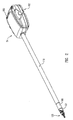
- FIG. 2 a perspective view is shown of a surgical instrument 54 including a modular force sensor apparatus 100 operably coupled to a distal end of a rigid shaft 110 and proximal to a wrist joint 121 in accordance with an embodiment of the present invention.
- An end portion 120 such as a surgical end effector, is coupled to force sensor apparatus 100 via the wrist joint 121.
- a housing 150 is operably coupled to a proximal end of the rigid shaft 110 and includes an interface 152 which mechanically and electrically couples instrument 54 to the manipulator 51.
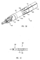
- FIG. 3A shows a perspective view of modular force sensor apparatus 100 including in one embodiment a tube 102 including a number (e.g., 3, 4, 6, or 8) of strain gauges 104 (e.g., 104a and 104b) mounted to a surface of tube 102 and oriented axially (parallel to the lengthwise axis z of the tube).
- FIG. 3B shows the modular force sensor apparatus 100 of FIG.
- FIG. 3A operably coupled to a shaft 110 and end portion 120 of a surgical instrument in accordance with an embodiment of the present invention.
- FIG. 3C shows a cross-section view of modular force sensor apparatus 100 including a cover or sleeve 113 over tube 102.
- force sensor apparatus 100 is a separately manufacturable module adapted for incorporation as part of the shaft 110 of laparoscopic surgical instrument 54 at a prescribed distance from the tip where there may be an articulated wrist with specialized jaws, cutting devices, or other end portion 120.
- tube 102 may be made of a sufficiently strong material and may be spool shaped, including end portions 102b, 102a with a depressed portion 102a therebetween. Strain gauges 104 may be mounted on the surface of depressed portion 102a.
- Proximal tube portion 102c operably couples to the shaft 110 of surgical instrument 54 and distal tube portion 102b operably couples to a wrist joint 121.
- the diameter of the completed force sensor apparatus matches the diameter of the instrument shaft, thus allowing the entire assembly of the instrument (including the coupled force sensor apparatus) to pass through a cannula or a seal without added friction or snagging.
- Force sensor apparatus 100 includes a through passage 109 for end portion actuation cables or rods. End features 108 of end portion 102b insure secure mounting and angular alignment to the main instrument shaft and wrist/jaw/other end portion subassembly of the instrument.
- Wire leads or optic fibers 116 e.g., shielded twisted pairs, coax, or fiber
- the wire leads or optic fibers 116 may then be embedded in an adhesive potting compound such as epoxy.
- cover 113 is positioned over and encapsulates the mounted strain gauges 104 and other circuit elements on the surface of the tube 102, thereby providing mechanical protection of the sensors.
- cover 113 is a mechanically protective woven sleeve potted on depressed portion 102a and is comprised of a woven resin impregnated fiberglass or metal braid electrical shielding.
- strain gauges 104 may be spaced in a ring at intervals around the circumference of the tube 102 (e.g., 3 gauges at 120 degrees or 4 gauges at 90 degrees).
- the signals from the sensors are combined arithmetically in various sums and differences to obtain measures of three perpendicular forces (e.g., F x , F y , and F z ) exerted upon the instrument tip and the torques about the two axes perpendicular to the shaft axis (i.e., axes x and y).
- the measurement of the forces is made independent of the orientation and effective lever arm length of an articulated wrist mechanism at the distal end of the instrument when two sets or rings of gauges are utilized.
- Forces exerted against end portion 120 are detected by the force sensing elements, which may be operably coupled to the servo control via an interrogator or a processor for notifying the surgeon of these forces (e.g., via master(s)).
- various strain gauges may be used, including but not limited to conventional foil type resistance gauges, semiconductor gauges, optic fiber type gauges using Bragg grating or Fabry-Perot technology, or others, such as strain sensing surface acoustic wave (SAW) devices.
- SAW strain sensing surface acoustic wave
- FBG Optic fiber Bragg grating
- Both fiber technologies require an interrogator unit that decodes the optically encoded strain information into electrical signals compatible with the computer control hardware of the robotic surgical system.
- a processor may then be used to calculate forces according to the signals from the strain gauges/sensors.
- strain gauge bridge circuits are completed in a manner to give the best signal for bending loads due to the lateral forces (F x and F y ) exerted on the instrument tip jaws.
- active components such as bare die op-amps and passive components such as secondary resistors or capacitors may be attached adjacent to the strain gauges connected by bond wires or optic fibers or thick film circuit traces in the manner of hybrid circuits to amplify, filter, and/or modulate the gauge output signals to reject noise sources.
- passive components such as secondary resistors or capacitors may be attached adjacent to the strain gauges connected by bond wires or optic fibers or thick film circuit traces in the manner of hybrid circuits to amplify, filter, and/or modulate the gauge output signals to reject noise sources.
- Such components are not needed for fiber optic gauges.
- Surgical instrument 54 to which force sensor apparatus 100 couples may include a circumferentially coiled insulated flex circuit style service loop of parallel conductive traces at the proximal end of the instrument shaft 110 permitting the substantially free rotation of the instrument shaft while conducting the input gauge excitation power and output gauge signals to stationary housing 150 of the instrument 54.
- Housing 150 operably interfaces with a robotic manipulator arm 51, in one embodiment via a sterile adaptor interface 152.
- Applicable housings, sterile adaptor interfaces, and manipulator arms are disclosed in U.S. Patent Application No. 11/314,040 and U.S. Provisional Application No. 60/752,755, both filed on December 20, 2005 , the full disclosures of which (including all references incorporated by reference therein) are incorporated by reference herein for all purposes.
- Applicable shafts, end portions, housings, sterile adaptors, and manipulator arms are available from Intuitive Surgical Inc. of Sunnyvale, California.
- end portion 120 has a range of motion that includes pitch and yaw motion, rotation about the z-axis, and actuation of an end effector, via cables through shaft 110 and housing 150 that transfers motion and electrical signals from the manipulator arm 51. Movement of end portion 120 along the x, y, and z axes may be provided by the manipulator arm 51.
- Embodiments of drive assemblies, arms, forearm assemblies, adaptors, and other applicable parts are described for example in U.S. Patent Nos. 6,331,181 , 6,491,701 , and 6,770,081 , the full disclosures of which (including disclosures incorporated by reference therein) are incorporated herein by reference for all purposes.
- various surgical instruments may be improved in accordance with the present invention, including but not limited to tools with and without end effectors, such as jaws, scissors, graspers, needle holders, micro-dissectors, staple appliers, tackers, suction irrigation tools, clip appliers, cutting blades, irrigators, catheters, and suction orifices.
- the surgical instrument may comprise an electrosurgical probe for ablating, resecting, cutting or coagulating tissue.
- Such surgical instruments are commercially available from Intuitive Surgical, Inc. of Sunnyvale, California.
- the calibration data may be programmed into an integrated circuit embedded in the instrument so that the surgical system using the individual instrument can correctly identify and apply its correction factors and offsets while the instrument is in use.
- force sensor apparatus 100 of the present invention is adaptable to the size and shape constraints of robotic endoscopic surgical instruments and is suitable for a variety of instruments. Accordingly, end portions 102b, 102c may be formed into various applicable shapes and sizes. Furthermore, force sensor apparatus 100 may be manufactured, tested, and calibrated as a separate modular component and brought together with other components in the conventional instrument assembly process. Also, the sensor may be a slip on module with suitable electrical contacts that mate with contacts on the instrument shaft permitting a higher value sensor to be used with lower cost instruments of limited cycle life. In addition, the sensor structural member 102 may be comprised of an advantageous material, which may be a different material than the instrument shaft 110 whose design considerations may compromise the properties required for the sensor.
- FIGS. 4A through 4D a modular force sensor apparatus 200 is illustrated in accordance with another embodiment of the present invention.
- the descriptions of substantially similar parts or elements as those described above with respect to FIGS. 1-3 are applicable in this embodiment with respect to FIGS. 4A-4D , although redundant descriptions will be omitted.
- FIG. 4A is a perspective view of an inner tube 218 of modular force sensor apparatus 200 in accordance with an embodiment of the present invention.
- Inner tube 218 includes a proximal raised end portion 218b and a depressed portion 218a.
- Strain gauges as described above with respect to FIGS. 1-3 , may be mounted on the surface of depressed portion 218a.
- Raised end portion 218b may include grooves 112 for routing of wire leads or optic fibers from strain gauges 204.
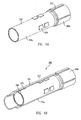
- FIG. 4B is a partial cross-sectional view of an outer tube 214 over the inner tube 218.
- outer tube 214 of force sensor apparatus 200 is a concentric tubular structural member made of sufficiently strong materials that can encapsulate the strain gauges and other electronics within an annular gap between the inner and outer tubes 218 and 214.
- the concentric tubes are joined rigidly at the proximal end adjacent proximal portion 218b while a narrow annular gap between the distal ends near a distal portion is filled with an elastomeric material 215 that prevents the high and varying axial forces of the wrist and jaw actuator cable or rods from being transmitted through the inner tube carrying the strain gauges.
- the partially isolated tube carrying the gauges may be either the outer or the inner tube.
- the non-isolated tube of the pair may carry the entire axial cable load.
- the gauges may be placed on the interior tube to isolate the gauges from the environment.
- the outer tube 214 carries the axial cable forces and also permits the outer tube to provide mechanical protection and potentially act as EMI shielding to the gauges 204 on the inner tube 218.
- FIG. 4C highlights elastomeric material 215 between the inner tube 21B and outer tube 214 of the modular force sensor apparatus 200, and wires or fiber optic cables 216 operably coupled to gauges 204.
- FIG. 4D shows a partial cross-sectional view of the modular force sensor apparatus 200 operably coupled proximal to a wrist joint 221 of a surgical instrument in accordance with an embodiment of the present invention.
- Leads 216 e.g., shielded twisted pairs, coax, or optic fiber
- the leads 216 may then be embedded in an adhesive potting compound such as an epoxy.
- the wire routing may be simplified by not requiring a rotating joint service loop.
- the relative shear and compressive properties of elastomers enables this design concept.
- a suitable elastomer 215 with a low shear modulus permits the relative compression and extension of the cable load carrying tube with respect to the sensor carrying tube (which is connected rigidly at only one end of the tubes as mentioned above).
- cable loads and load changes do not affect the sensors.
- an elastomer confined between two relatively rigid surfaces where the gap between the surfaces is small compared to the extent of the surfaces behaves as a nearly incompressible rigid connection in the direction normal to the confining surfaces, in this case the radial direction of the combined annular tube structure. This causes bending moments carried in the axially loaded tube to be transmitted to and shared by the sensor tube.
- the sensor tube can advantageously detect the bending moments due to lateral loads on the instrument wrist and jaws without significant interference or "noise" from the higher varying axial cable loads carried by the other tube.
- the decoupling of the load carrying members in an endoscopic surgical instrument force sensor enables the separation of undesired jaw actuator tendon forces from desired lateral jaw load induced bending moments on the force sensor.
- the desired effect of axially de-constraining the sensor carrying tube from the cable load carrying tube at one end may be obtained by inserting an annular ring of a more rigid low friction material in the annular gap between the unconnected ends of the tubes machined for a very close fit, thereby permitting the relative axial motion but transmitting the lateral motion associated with bending moments due to the lateral tip forces.
- Another alternative is to make the tubes with a very close fit and apply a low friction coating to one or both surfaces at the distal end.
- these alternatives may create a small deadband in sensor response depending on how close a fit may be reliably obtained.
- the expansion thermal coefficients of the inner and outer tubes must also be matched or the required close fit may bind when heated or cooled.
Abstract
Description
- The present invention relates generally to surgical robot systems and, more particularly, to an improved system, apparatus, and method for sensing forces applied to a surgical instrument.
- In robotically-assisted surgery, the surgeon typically operates a master controller to control the motion of surgical instruments at the surgical site from a location that may be remote from the patient (e.g., across the operating room, in a different room or a completely different building from the patient). The master controller usually includes one or more hand input devices, such as handheld wrist gimbals, joysticks, exoskeletal gloves, handpieces or the like, which are operatively coupled to the surgical instruments through a controller with servo motors for articulating the instruments' position and orientation at the surgical site. The servo motors are typically part of an electromechanical device or surgical manipulator arm ("the slave") that includes a plurality of joints, linkages, etc., that are connected together to support and control the surgical instruments that have been introduced directly into an open surgical site or through trocar sleeves inserted through incisions into a body cavity, such as the patient's abdomen. Depending on the surgical procedure, there are available a variety of surgical instruments, such as tissue graspers, needle drivers, electrosurgical cautery probes, etc., to perform various functions for the surgeon, e.g., retracting tissue, holding or driving a needle, suturing, grasping a blood vessel, or dissecting, cauterizing or coagulating tissue. A surgeon may employ a large number of different surgical instruments/tools during a procedure.
- This new method of performing telerobotic surgery through remote manipulation has created many new challenges. One such challenge is providing the surgeon with the ability to accurately "feel" the tissue that is being manipulated by the surgical instrument via the robotic manipulator. The surgeon must rely on visual indications of the forces applied by the instruments or sutures. It is desirable to sense the forces and torques applied to the tip of the instrument, such as an end effector (e.g., jaws, grasper, blades, etc.) of robotic endoscopic surgical instruments, in order to feed the forces and torques back to the surgeon user through the system hand controls or by other means such as visual display or audible tone. One device for this purpose from the laboratory of G. Hirzinger at DLR is described in "Review of Fixtures for Low-Invasiveness Surgery" by F. Cepolina and R.C. Michelini, Int'l Journal of Medical Robotics and Computer Assisted Surgery, Vol. 1, Issue 1, , the contents of which are incorporated by reference herein for all purposes. However, that design disadvantageously places a force sensor distal to (or outboard of) the wrist joints, thus requiring wires or optic fibers to be routed through the flexing wrist joint and also requiring the yaw and grip axes to be on separate pivot axes.
- Another problem has been fitting and positioning the necessary wires for mechanical actuation of end effectors in as small a space as possible as relatively small instruments are typically desirable for performing surgery.
- What is needed, therefore, are improved telerobotic systems and methods for remotely controlling surgical instruments at a surgical site on a patient. In particular, these systems and methods should be configured to provide accurate feedback of forces and torques to the surgeon to improve user awareness and control of the instruments.
- The present invention provides an apparatus, system, and method for improving force and torque feedback to and sensing by the surgeon performing a robotic surgery. In one embodiment, a modular force sensor includes a tube portion including a plurality of strain gauges, a proximal tube portion for operably coupling to a shaft of a surgical instrument that may be operably coupled to a manipulator arm of a robotic surgical system, and a distal tube portion for proximally coupling to a wrist joint coupled to an end portion.
- Groups of axially oriented strain gauges are positioned on or near a distal end of an instrument shaft proximal to (or inboard of) a moveable wrist of a robotic surgical instrument via a modular apparatus to sense forces and torques at the distal tip of the instrument without errors due to changes in the configuration of the tip (such as with a moveable wrist) or steady state temperature variations.
- Advantageously, the present invention improves the sensing and feedback of forces and/or torques to the surgeon and substantially eliminates the problem of passing delicate wires through the flexible wrist joint of the instrument. A force sensor apparatus may be manufactured, tested, and calibrated as a separate modular component and brought together with other components in the conventional instrument assembly process. In addition, it is possible to choose a material for the sensor structural member different from the material of the instrument shaft whose design considerations may compromise the mechanical properties required for the sensor.
- The scope of the invention is defined by the claims, which are incorporated into this section by reference. A more complete understanding of embodiments of the present invention will be afforded to those skilled in the art, as well as a realization of additional advantages thereof, by a consideration of the following detailed description of one or more embodiments. Reference will be made to the appended sheets of drawings that will first be described briefly.
-
-
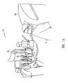
FIG. 1A is a perspective view of a robotic surgical system and method in accordance with an embodiment of the present invention. -
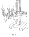
FIG. 1B is a perspective view of a robotic surgical arm cart system of the robotic surgical system inFIG. 1A in accordance with an embodiment of the present invention. -
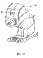
FIG. 1C is a front perspective view of a master console of the robotic surgical system inFIG. 1A in accordance with an embodiment of the present invention. -
FIG. 2 is a perspective view of a surgical instrument including a modular force sensor apparatus operably coupled proximal (or inboard) to a wrist joint in accordance with an embodiment of the present invention. -
FIG. 3A is a perspective view of a modular force sensor apparatus in accordance with an embodiment of the present invention. -
FIG. 3B illustrates the modular force sensor ofFIG. 3A operably coupled to a shaft and end portion of a surgical instrument in accordance with an embodiment of the present invention. -
FIG. 3C illustrates the modular force sensor ofFIG. 3A with a protective cover over a portion of the modular force sensor in accordance with an embodiment of the present invention. -
FIG. 4A is a perspective view of an inner tube of a modular force sensor apparatus in accordance with another embodiment of the present invention. -
FIG. 4B is a partial cross-sectional view of an outer tube/cover over the inner tube ofFIG. 4A of the modular force sensor apparatus in accordance with an embodiment of the present invention. -
FIG. 4C shows intervening material between the inner and outer tubes ofFIG. 4B of the modular force sensor apparatus and wires or fiber optic cables operably coupled to the modular force sensor apparatus in accordance with an embodiment of the present invention. -
FIG. 4D shows a partial cross-sectional view of the modular force sensor apparatus operably coupled proximal to (or inboard of) a wrist joint of a surgical instrument in accordance with an embodiment of the present invention. - Embodiments of the present invention and their advantages are best understood by referring to the detailed description that follows. It should be appreciated that like reference numerals are used to identify like elements illustrated in one or more of the figures. It should also be appreciated that the figures may not be necessarily drawn to scale.
- The present invention provides a multi-component system, apparatus, and method for sensing forces applied to tissue while performing robotically-assisted surgical procedures on a patient, particularly including open surgical procedures, neurosurgical procedures, such as stereotaxy, and endoscopic procedures, such as laparoscopy, arthroscopy, thoracoscopy and the like. The apparatus and method of the present invention is particularly useful as part of a telerobotic surgical system that allows the surgeon to manipulate the surgical instruments through a servomechanism from a remote location from the patient. To that end, the manipulator apparatus or slave of the present invention will usually be driven by a kinematically-equivalent master having six or more degrees of freedom (e.g., 3 degrees of freedom for position and 3 degrees of freedom for orientation) to form a telepresence system with force reflection. A description of a suitable slave-master system can be found in
U.S. Patent Application No. 08/517,053, filed Aug. 21, 1995 - Referring to the drawings in detail, wherein like numerals indicate like elements, a robotic
surgical system 10 is illustrated according to an embodiment of the present invention. As shown inFIGS. 1A through 1C ,robotic system 10 generally includes one or moresurgical manipulator assemblies 51 mounted to or near an operating table O, and a master control assembly located at a surgeon'sconsole 90 for allowing the surgeon S to view the surgical site and to control themanipulator assemblies 51. Thesystem 10 will also include one or more viewing scope assemblies and a plurality ofsurgical instrument assemblies 54 adapted for being removably coupled to the manipulator assemblies 51 (discussed in more detail below).Robotic system 10 usually includes at least twomanipulator assemblies 51 and preferably threemanipulator assemblies 51. The exact number ofmanipulator assemblies 51 will depend on the surgical procedure and the space constraints within the operating room among other factors. As discussed in detail below, one of theassemblies 51 will typically operate a viewing scope assembly (e.g., in endoscopic procedures) for viewing the surgical site, while theother manipulator assemblies 51 operatesurgical instruments 54 for performing various procedures on the patient P. - The control assembly may be located at a surgeon's
console 90 which is usually located in the same room as operating table 0 so that the surgeon may speak to his/her assistant(s) and directly monitor the operating procedure. However, it should be understood that the surgeon S can be located in a different room or a completely different building from the patient P. The master control assembly generally includes a support, a monitor for displaying an image of the surgical site to the surgeon S, and one or more master(s) for controllingmanipulator assemblies 51. Master(s) may include a variety of input devices, such as hand-held wrist gimbals, joysticks, glovers, trigger-guns, hand-operated controllers, voice recognition devices or the like. Preferably, master(s) will be provided with the same degrees of freedom as the associatedsurgical instrument assemblies 54 to provide the surgeon with telepresence, the perception that the surgeon is immediately adjacent to and immersed in the surgical site, and intuitiveness, the perception that the master(s) are integral with theinstruments 54 so that the surgeon has a strong sense of directly and intuitively controllinginstruments 54 as if they are part of his hands. Position, force, and tactile feedback sensors (not shown) may also be employed oninstrument assemblies 54 to transmit position, force, and tactile sensations from the surgical instrument back to the surgeon's hands as he/she operates the telerobotic system. One suitable system and method for providing telepresence to the operator is described inU.S. Patent Application No. 08/517,053, filed Aug. 21, 1995 - The
monitor 94 will be suitably coupled to the viewing scope assembly such that an image of the surgical site is provided adjacent the surgeon's hands on surgeon console. Preferably, monitor 94 will display an image on a display that is oriented so that the surgeon feels that he or she is actually looking directly down onto the operating site. To that end, an image of thesurgical instruments 54 appears to be located substantially where the operator's hands are located even though the observation points (i.e., the endoscope or viewing camera) may not be from the point of view of the image. In addition, the real-time image is preferably transformed into a stereo image such that the operator can manipulate the end effector and the hand control as if viewing the workspace in substantially true presence. By true presence, it is meant that the presentation of an image is a true stereo image simulating the viewpoint of an operator that is physically manipulating thesurgical instruments 54. Thus, a controller (not shown) transforms the coordinates of thesurgical instruments 54 to a perceived position so that the stereo image is the image that one would see if the camera or endoscope was located directly behind thesurgical instruments 54. A suitable coordinate transformation system for providing this virtual image is described inU.S. Patent Application No. 08/239,086, filed May 5, 1994 U.S. Patent No. 5,631,973 , the complete disclosure of which is incorporated herein by reference for all purposes. - A servo control is provided for transferring the mechanical motion of masters to
manipulator assemblies 51. The servo control may be separate from, or integral with theconsole 90. The servo control will usually provide force and torque feedback from thesurgical instruments 51 to the hand-operated masters. In addition, the servo control may include a safety monitoring controller (not shown) to safely halt system operation or at least inhibit all robot motion in response to recognized undesirable conditions (e.g., exertion of excessive force on the patient, mismatched encoder readings, etc.). The servo control preferably has a servo bandwidth with a 3 dB cut off frequency of at least 10 hz so that the system can quickly and accurately respond to the rapid hand motions used by the surgeon and yet to filter out undesirable surgeon hand tremors. To operate effectively with this system,manipulator assemblies 51 have a relatively low inertia, and the drive motors have relatively low ratio gear or pulley couplings. Any suitable conventional or specialized servo control may be used in the practice of the present invention, with those incorporating force and torque feedback being particularly preferred for telepresence operation of the system. - Referring to
FIG. 2 , a perspective view is shown of asurgical instrument 54 including a modularforce sensor apparatus 100 operably coupled to a distal end of arigid shaft 110 and proximal to a wrist joint 121 in accordance with an embodiment of the present invention. Anend portion 120, such as a surgical end effector, is coupled to forcesensor apparatus 100 via thewrist joint 121. Ahousing 150 is operably coupled to a proximal end of therigid shaft 110 and includes aninterface 152 which mechanically and electrically couplesinstrument 54 to themanipulator 51. - Referring now to
FIGS. 3A-3C in conjunction withFIGS. 1A-1C and 2 , an improved apparatus, system, and method for sensing and feedback of forces and/or torques to the surgeon will be described in accordance with an embodiment of the present invention.FIG. 3A shows a perspective view of modularforce sensor apparatus 100 including in one embodiment atube 102 including a number (e.g., 3, 4, 6, or 8) of strain gauges 104 (e.g., 104a and 104b) mounted to a surface oftube 102 and oriented axially (parallel to the lengthwise axis z of the tube).FIG. 3B shows the modularforce sensor apparatus 100 ofFIG. 3A operably coupled to ashaft 110 andend portion 120 of a surgical instrument in accordance with an embodiment of the present invention.FIG. 3C shows a cross-section view of modularforce sensor apparatus 100 including a cover orsleeve 113 overtube 102. - In accordance with an embodiment of the present invention,
force sensor apparatus 100 is a separately manufacturable module adapted for incorporation as part of theshaft 110 of laparoscopicsurgical instrument 54 at a prescribed distance from the tip where there may be an articulated wrist with specialized jaws, cutting devices, orother end portion 120. In one example,tube 102 may be made of a sufficiently strong material and may be spool shaped, includingend portions 102b, 102a with a depressed portion 102a therebetween. Strain gauges 104 may be mounted on the surface of depressed portion 102a.Proximal tube portion 102c operably couples to theshaft 110 ofsurgical instrument 54 anddistal tube portion 102b operably couples to awrist joint 121. In one example, the diameter of the completed force sensor apparatus matches the diameter of the instrument shaft, thus allowing the entire assembly of the instrument (including the coupled force sensor apparatus) to pass through a cannula or a seal without added friction or snagging. -
Force sensor apparatus 100 includes a throughpassage 109 for end portion actuation cables or rods. End features 108 ofend portion 102b insure secure mounting and angular alignment to the main instrument shaft and wrist/jaw/other end portion subassembly of the instrument. Wire leads or optic fibers 116 (e.g., shielded twisted pairs, coax, or fiber) from the strain gauges 104 may be inlaid intogrooves 112 inproximal tube portion 102c oftube 102 and matching grooves in theshaft 110 of thesurgical instrument 54. The wire leads oroptic fibers 116 may then be embedded in an adhesive potting compound such as epoxy. - In one embodiment, as illustrated in
FIG. 3C ,cover 113 is positioned over and encapsulates the mountedstrain gauges 104 and other circuit elements on the surface of thetube 102, thereby providing mechanical protection of the sensors. In one example, cover 113 is a mechanically protective woven sleeve potted on depressed portion 102a and is comprised of a woven resin impregnated fiberglass or metal braid electrical shielding. - As disclosed in
U.S. Provisional Application No. 60/755,108, filed December 30, 2005 strain gauges 104 may be spaced in a ring at intervals around the circumference of the tube 102 (e.g., 3 gauges at 120 degrees or 4 gauges at 90 degrees). The signals from the sensors are combined arithmetically in various sums and differences to obtain measures of three perpendicular forces (e.g., Fx, Fy, and Fz) exerted upon the instrument tip and the torques about the two axes perpendicular to the shaft axis (i.e., axes x and y). In accordance with the present invention, the measurement of the forces is made independent of the orientation and effective lever arm length of an articulated wrist mechanism at the distal end of the instrument when two sets or rings of gauges are utilized. Forces exerted againstend portion 120 are detected by the force sensing elements, which may be operably coupled to the servo control via an interrogator or a processor for notifying the surgeon of these forces (e.g., via master(s)). It is understood that by adding a second ring of similarly oriented gauges (e.g., two sets of 3 gauges or two sets of 4 gauges) at a different axial position on the tube, additional applied torque information (e.g., Tx and Ty) and elimination of dependence of the force data on instrument wrist length, orientation, and resulting jaw distance, may be obtained. - In one example, various strain gauges may be used, including but not limited to conventional foil type resistance gauges, semiconductor gauges, optic fiber type gauges using Bragg grating or Fabry-Perot technology, or others, such as strain sensing surface acoustic wave (SAW) devices. Optic fiber Bragg grating (FBG) gauges may be advantageous in that two sensing elements may be located along one fiber at a known separation, thereby only requiring the provision of four fibers along the instrument shaft.
- Both fiber technologies require an interrogator unit that decodes the optically encoded strain information into electrical signals compatible with the computer control hardware of the robotic surgical system. A processor may then be used to calculate forces according to the signals from the strain gauges/sensors.
- Additionally, there may be co-mounted unstrained gauges or Poisson strained gauges oriented in the circumferential direction adjacent to each axial gauge and incorporated in the bridge completion circuits to eliminate temperature effects. The strain gauge bridge circuits are completed in a manner to give the best signal for bending loads due to the lateral forces (Fx and Fy) exerted on the instrument tip jaws.
- For resistive foil or semiconductor strain gauges, active components such as bare die op-amps and passive components such as secondary resistors or capacitors may be attached adjacent to the strain gauges connected by bond wires or optic fibers or thick film circuit traces in the manner of hybrid circuits to amplify, filter, and/or modulate the gauge output signals to reject noise sources. Such components are not needed for fiber optic gauges.
-
Surgical instrument 54 to whichforce sensor apparatus 100 couples may include a circumferentially coiled insulated flex circuit style service loop of parallel conductive traces at the proximal end of theinstrument shaft 110 permitting the substantially free rotation of the instrument shaft while conducting the input gauge excitation power and output gauge signals tostationary housing 150 of theinstrument 54. -
Housing 150 operably interfaces with arobotic manipulator arm 51, in one embodiment via asterile adaptor interface 152. Applicable housings, sterile adaptor interfaces, and manipulator arms are disclosed inU.S. Patent Application No. 11/314,040 andU.S. Provisional Application No. 60/752,755, both filed on December 20, 2005 - In a preferred configuration,
end portion 120 has a range of motion that includes pitch and yaw motion, rotation about the z-axis, and actuation of an end effector, via cables throughshaft 110 andhousing 150 that transfers motion and electrical signals from themanipulator arm 51. Movement ofend portion 120 along the x, y, and z axes may be provided by themanipulator arm 51. Embodiments of drive assemblies, arms, forearm assemblies, adaptors, and other applicable parts are described for example inU.S. Patent Nos. 6,331,181 ,6,491,701 , and6,770,081 , the full disclosures of which (including disclosures incorporated by reference therein) are incorporated herein by reference for all purposes. - It is noted that various surgical instruments may be improved in accordance with the present invention, including but not limited to tools with and without end effectors, such as jaws, scissors, graspers, needle holders, micro-dissectors, staple appliers, tackers, suction irrigation tools, clip appliers, cutting blades, irrigators, catheters, and suction orifices. Alternatively, the surgical instrument may comprise an electrosurgical probe for ablating, resecting, cutting or coagulating tissue. Such surgical instruments are commercially available from Intuitive Surgical, Inc. of Sunnyvale, California.
- For the methods and apparatus mentioned above, it may be advantageous to use a calibration process in which combinations of forces and torques are applied to the instrument tip serially, simultaneously, or in combinations while correction factors and offsets are determined to apply to the theoretical equations for combining the gauge outputs to obtain Fx, Fy, Fz, Tx, and Ty. This calibration may be done either by directly calculating the correction factors and offsets or by a learning system such as a neural network embedded in the calibration fixture or in the instrument itself. In any calibration method, the calibration data may be programmed into an integrated circuit embedded in the instrument so that the surgical system using the individual instrument can correctly identify and apply its correction factors and offsets while the instrument is in use.
- Advantageously,
force sensor apparatus 100 of the present invention is adaptable to the size and shape constraints of robotic endoscopic surgical instruments and is suitable for a variety of instruments. Accordingly, endportions force sensor apparatus 100 may be manufactured, tested, and calibrated as a separate modular component and brought together with other components in the conventional instrument assembly process. Also, the sensor may be a slip on module with suitable electrical contacts that mate with contacts on the instrument shaft permitting a higher value sensor to be used with lower cost instruments of limited cycle life. In addition, the sensorstructural member 102 may be comprised of an advantageous material, which may be a different material than theinstrument shaft 110 whose design considerations may compromise the properties required for the sensor. - Referring now to
FIGS. 4A through 4D , a modularforce sensor apparatus 200 is illustrated in accordance with another embodiment of the present invention. The descriptions of substantially similar parts or elements as those described above with respect toFIGS. 1-3 are applicable in this embodiment with respect toFIGS. 4A-4D , although redundant descriptions will be omitted. -
FIG. 4A is a perspective view of aninner tube 218 of modularforce sensor apparatus 200 in accordance with an embodiment of the present invention.Inner tube 218 includes a proximal raisedend portion 218b and a depressed portion 218a. Strain gauges, as described above with respect toFIGS. 1-3 , may be mounted on the surface of depressed portion 218a. Raisedend portion 218b may includegrooves 112 for routing of wire leads or optic fibers from strain gauges 204. -
FIG. 4B is a partial cross-sectional view of anouter tube 214 over theinner tube 218. In one example,outer tube 214 offorce sensor apparatus 200 is a concentric tubular structural member made of sufficiently strong materials that can encapsulate the strain gauges and other electronics within an annular gap between the inner andouter tubes proximal portion 218b while a narrow annular gap between the distal ends near a distal portion is filled with anelastomeric material 215 that prevents the high and varying axial forces of the wrist and jaw actuator cable or rods from being transmitted through the inner tube carrying the strain gauges. It is noted that the partially isolated tube carrying the gauges may be either the outer or the inner tube. The non-isolated tube of the pair may carry the entire axial cable load. Preferably, the gauges may be placed on the interior tube to isolate the gauges from the environment. In such an embodiment, theouter tube 214 carries the axial cable forces and also permits the outer tube to provide mechanical protection and potentially act as EMI shielding to thegauges 204 on theinner tube 218. -
FIG. 4C highlightselastomeric material 215 between the inner tube 21B andouter tube 214 of the modularforce sensor apparatus 200, and wires orfiber optic cables 216 operably coupled to gauges 204.FIG. 4D shows a partial cross-sectional view of the modularforce sensor apparatus 200 operably coupled proximal to awrist joint 221 of a surgical instrument in accordance with an embodiment of the present invention. Leads 216 (e.g., shielded twisted pairs, coax, or optic fiber) from the strain gauges 204 may be inlaid intogrooves 212 inproximal tube portion 218b oftube 218 and matching grooves in theshaft 210 of a surgical instrument. The leads 216 may then be embedded in an adhesive potting compound such as an epoxy. - In one example, if an outer sensor carrying tube is mounted stationary at the rear mechanism housing, the wire routing may be simplified by not requiring a rotating joint service loop.
- Advantageously, the relative shear and compressive properties of elastomers enables this design concept. A
suitable elastomer 215 with a low shear modulus permits the relative compression and extension of the cable load carrying tube with respect to the sensor carrying tube (which is connected rigidly at only one end of the tubes as mentioned above). Thus, cable loads and load changes do not affect the sensors. On the other hand, an elastomer confined between two relatively rigid surfaces where the gap between the surfaces is small compared to the extent of the surfaces behaves as a nearly incompressible rigid connection in the direction normal to the confining surfaces, in this case the radial direction of the combined annular tube structure. This causes bending moments carried in the axially loaded tube to be transmitted to and shared by the sensor tube. Thus, the sensor tube can advantageously detect the bending moments due to lateral loads on the instrument wrist and jaws without significant interference or "noise" from the higher varying axial cable loads carried by the other tube. Advantageously, the decoupling of the load carrying members in an endoscopic surgical instrument force sensor enables the separation of undesired jaw actuator tendon forces from desired lateral jaw load induced bending moments on the force sensor. - Alternatively, the desired effect of axially de-constraining the sensor carrying tube from the cable load carrying tube at one end may be obtained by inserting an annular ring of a more rigid low friction material in the annular gap between the unconnected ends of the tubes machined for a very close fit, thereby permitting the relative axial motion but transmitting the lateral motion associated with bending moments due to the lateral tip forces. Another alternative is to make the tubes with a very close fit and apply a low friction coating to one or both surfaces at the distal end. However, these alternatives may create a small deadband in sensor response depending on how close a fit may be reliably obtained. The expansion thermal coefficients of the inner and outer tubes must also be matched or the required close fit may bind when heated or cooled.
- It should also be understood that the same decoupling effect achieved with concentric tubes as described above may potentially be achieved with alternating axial finger-like members half (or some number) of which carry the axial cable loads while the alternating (or remaining) ones carry the bending loads. Again, these members may be rigidly connected at the proximal end while they are decoupled in the axial direction at the distal end.
- Embodiments described above illustrate but do not limit the invention. It should also be understood that numerous modifications and variations are possible in accordance with the principles of the present invention. For example, the number of strain gauges and their configuration may vary but must allow for applicable force and torque determinations. Accordingly, the scope of the invention is defined only by the following claims.
- The present application also includes the following numbered clauses:
- 1. A modular force sensor apparatus, comprising:
- a tube portion including a plurality of strain gauges;
- a cover over the plurality of strain gauges;
- a proximal tube portion for operably coupling to a shaft of a surgical instrument that may be operably coupled to a manipulator arm of a robotic surgical system; and
- a distal tube portion for proximally coupling to a wrist joint coupled to an end portion.
- 2. The apparatus of clause 1, wherein the tube portion is depressed and the proximal tube portion is raised.
- 3. The apparatus of clause 1, wherein the tube portion comprises a material different from the material of the shaft of the surgical instrument.
- 4. The apparatus of clause 1, wherein the plurality of strain gauges includes eight strain gauges in two groups of four, with each of the strain gauges in a group being spaced apart by 90 degrees around the shaft.
- 5. The apparatus of clause 1, wherein the plurality of strain gauges includes six strain gauges in two groups of three, with each of the strain gauges in a group being spaced apart by 120 degrees around the shaft.
- 6. The apparatus of clause 1, wherein the plurality of strain gauges includes four strain gauges spaced apart by 90 degrees around the shaft.
- 7. The apparatus of clause 1, wherein the plurality of strain gauges includes three strain gauges spaced apart by 120 degrees around the shaft.
- 8. The apparatus of clause 1, wherein each strain gauge is aligned with one other strain gauge along an axis parallel to a lengthwise axis of the depressed tube portion.
- 9. The apparatus of clause 1, wherein the primary strain sensing direction of each of the strain gauges is oriented parallel to the shaft lengthwise axis.
- 10. The apparatus of clause 1, wherein the plurality of strain gauges is selected from the group consisting of fiber optic, foil, surface acoustic wave, and semiconductor type strain gauges.
- 11. The apparatus of clause 1, wherein a strain gauge is selected from the group consisting of a Fabry-Perot strain gauge and a fiber Bragg grating strain gauge.
- 12. The apparatus of clause 1, wherein the cover is comprised of material selected from the group consisting of fiberglass, a resin, and electrical shielding.
- 13. The apparatus of clause 1, wherein the proximal tube portion includes a plurality of grooves along the lengthwise axis of the tube portion.
- 14. The apparatus of clause 1, wherein the wrist joint shares a common pivot axis for yaw and grip axes.
- 15. The apparatus of clause 1, wherein the end portion is selected from the group consisting of jaws, scissors, graspers, needle holders, micro-dissectors, staple appliers, tackers, suction irrigation tools, clip appliers, cutting blades, cautery probes, irrigators, catheters, and suction orifices.
- 16. A modular force sensor apparatus, comprising:
- an inner tube including a tube portion having a plurality of strain gauges, and a proximal tube portion for operably coupling to a shaft of a surgical instrument that may be operably coupled to a manipulator arm of a robotic surgical system; and
- an outer tube covering the inner tube, wherein the outer tube is fixedly coupled to the proximal tube portion, and operably coupled to a distal tube portion of the inner tube for sensing lateral loads substantially without interfering axial loads from the outer tube.
- 17. The apparatus of clause 16, wherein the outer tube is operably coupled to the distal tube portion via an elastomer.
- 18. The apparatus of clause 16, wherein the outer tube is operably coupled to the distal tube portion via an annular ring of comprised of a low-friction material.
- 19. The apparatus of clause 16, wherein the outer tube is operably coupled to the distal tube portion via a low-friction coating.
- 20. The apparatus of clause 16, wherein the tube portion is comprised of a material different from the material of the shaft of the surgical instrument.
- 21. The apparatus of clause 16, wherein the plurality of strain gauges includes eight strain gauges in two groups of four, with each of the strain gauges in a group being spaced apart by 90 degrees around the shaft.
- 22. The apparatus of clause 16, wherein the plurality of strain gauges includes six strain gauges in two groups of three, with each of the strain gauges in a group being spaced apart by 120 degrees around the shaft.
- 23. The apparatus of clause 16, wherein the plurality of strain gauges includes four strain gauges spaced apart by 90 degrees around the shaft.
- 24. The apparatus of clause 16, wherein the plurality of strain gauges includes three strain gauges spaced apart by 120 degrees around the shaft.
- 25. The apparatus of clause 16, wherein the plurality of strain gauges is selected from the group consisting of fiber optic, foil, surface acoustic wave, and semiconductor type strain gauges.
- 26. The apparatus of clause 16, wherein a strain gauge is selected from the group consisting of a Fabry-Perot strain gauge and a fiber Bragg grating strain gauge.
- 27. The apparatus of clause 16, wherein the outer tube is comprised of a material selected from the group consisting of fiberglass, a resin, and electrical shielding.
- 28. The apparatus of clause 16, wherein the end portion is selected from the consisting of jaws, scissors, graspers needle holders, micro-dissectors, staple appliers, tackers, suction irrigation tools, clip appliers, cutting blades, cautery probes, irrigators, catheters, and suction orifices.
- 29. The apparatus of clause 16, wherein the proximal tube portion includes a plurality of grooves along the lengthwise axis of the tube portion.
Claims (15)
- A modular force sensor apparatus, comprising:an inner tube including a tube portion having a plurality of strain gauges, a proximal tube portion that operably couples to a shaft of a surgical instrument, and a distal tube portion that proximally couples to a wrist joint coupled to an end effector of the surgical instrument; andan outer tube covering at least a portion of the inner tube, wherein the outer tube is fixedly coupled to the proximal tube portion and operably coupled to the distal tube portion for sensing lateral loads substantially without interfering axial loads from the outer tube.
- The apparatus of Claim 1, wherein the outer tube is operably coupled to the distal tube portion via an elastomer.
- The apparatus of Claim 1, wherein the outer tube is operably coupled to the distal tube portion via an annular ring comprised of a low-friction material.
- The apparatus of Claim 1, wherein the outer tube is operably coupled to the distal tube portion via a low-friction coating.
- The apparatus of Claim 1, wherein the tube portion is comprised of a material different from the material of the shaft of the surgical instrument.
- The apparatus of Claim 1, wherein the proximal tube portion is raised relative to the tube portion.
- The apparatus of Claim 6, wherein the proximal tube portion includes a plurality of grooves along the lengthwise axis of the tube portion.
- The apparatus of Claim 1, wherein the plurality of strain gauges includes eight strain gauges in two groups of four, with each of the strain gauges in a group being spaced apart by 90 degrees around the shaft, or
wherein the plurality of strain gauges includes six strain gauges in two groups of three, with each of the strain gauges in a group being spaced apart by 120 degrees around the shaft, or
wherein the plurality of strain gauges includes four strain gauges spaced apart by 90 degrees around the shaft, or
wherein the plurality of strain gauges includes three strain gauges spaced apart by 120 degrees around the shaft. - The apparatus of Claim 1, wherein the plurality of strain gauges is selected from the group consisting of fiber optic, foil, surface acoustic wave, and semiconductor type strain gauges.
- The apparatus of Claim 1, wherein a strain gauge is selected from the group consisting of a Fabry-Perot strain gauge and a fiber Bragg grating strain gauge.
- The apparatus of Claim 1, wherein each of the plurality of strain gauges is aligned with one other strain gauge along an axis parallel to a lengthwise axis of the tube portion.
- The apparatus of Claim 1, wherein the primary strain sensing direction of each of the plurality of strain gauges is oriented parallel to a lengthwise axis of the shaft.
- The apparatus of Claim 1, wherein the outer tube is comprised of a material selected from the group consisting of fiberglass, a resin, and electrical shielding.
- The apparatus of Claim 1, wherein the wrist joint shares a common pivot axis for yaw and grip axes.
- The apparatus of Claim 1, wherein the end effector is selected from the group consisting of jaws, scissors, graspers, needle holders, micro-dissectors, staple appliers, tackers, suction irrigation tools, clip appliers, cutting blades, cautery probes, irrigators, catheters, and suction orifices.
Applications Claiming Priority (4)
| Application Number | Priority Date | Filing Date | Title |
|---|---|---|---|
| US75515705P | 2005-12-30 | 2005-12-30 | |
| US11/553,303 US7752920B2 (en) | 2005-12-30 | 2006-10-26 | Modular force sensor |
| EP06850942A EP1965717B1 (en) | 2005-12-30 | 2006-12-13 | Surgical instrument with modular force sensor |
| PCT/US2006/062000 WO2007120329A2 (en) | 2005-12-30 | 2006-12-13 | Modular force sensor |
Related Parent Applications (2)
| Application Number | Title | Priority Date | Filing Date |
|---|---|---|---|
| EP06850942A Division EP1965717B1 (en) | 2005-12-30 | 2006-12-13 | Surgical instrument with modular force sensor |
| EP06850942.1 Division | 2006-12-13 |
Publications (3)
| Publication Number | Publication Date |
|---|---|
| EP2289455A2 true EP2289455A2 (en) | 2011-03-02 |
| EP2289455A3 EP2289455A3 (en) | 2016-04-06 |
| EP2289455B1 EP2289455B1 (en) | 2019-11-13 |
Family
ID=38610003
Family Applications (2)
| Application Number | Title | Priority Date | Filing Date |
|---|---|---|---|
| EP06850942A Active EP1965717B1 (en) | 2005-12-30 | 2006-12-13 | Surgical instrument with modular force sensor |
| EP11150432.0A Active EP2289455B1 (en) | 2005-12-30 | 2006-12-13 | Modular force sensor |
Family Applications Before (1)
| Application Number | Title | Priority Date | Filing Date |
|---|---|---|---|
| EP06850942A Active EP1965717B1 (en) | 2005-12-30 | 2006-12-13 | Surgical instrument with modular force sensor |
Country Status (5)
| Country | Link |
|---|---|
| US (1) | US8281670B2 (en) |
| EP (2) | EP1965717B1 (en) |
| JP (2) | JP5152993B2 (en) |
| KR (1) | KR101296220B1 (en) |
| WO (1) | WO2007120329A2 (en) |
Cited By (2)
| Publication number | Priority date | Publication date | Assignee | Title |
|---|---|---|---|---|
| WO2011153084A3 (en) * | 2010-06-02 | 2012-04-19 | Mark Doyle | Flexible wrist-type element, methods, and use |
| CN110251233A (en) * | 2014-03-17 | 2019-09-20 | 直观外科手术操作公司 | System and method for being aligned with basic target |
Families Citing this family (151)
| Publication number | Priority date | Publication date | Assignee | Title |
|---|---|---|---|---|
| US8375808B2 (en) | 2005-12-30 | 2013-02-19 | Intuitive Surgical Operations, Inc. | Force sensing for surgical instruments |
| US8945095B2 (en) | 2005-03-30 | 2015-02-03 | Intuitive Surgical Operations, Inc. | Force and torque sensing for surgical instruments |
| US8465474B2 (en) | 2009-05-19 | 2013-06-18 | Intuitive Surgical Operations, Inc. | Cleaning of a surgical instrument force sensor |
| US8496647B2 (en) | 2007-12-18 | 2013-07-30 | Intuitive Surgical Operations, Inc. | Ribbed force sensor |
| US7930065B2 (en) | 2005-12-30 | 2011-04-19 | Intuitive Surgical Operations, Inc. | Robotic surgery system including position sensors using fiber bragg gratings |
| US8628518B2 (en) | 2005-12-30 | 2014-01-14 | Intuitive Surgical Operations, Inc. | Wireless force sensor on a distal portion of a surgical instrument and method |
| US9962066B2 (en) | 2005-12-30 | 2018-05-08 | Intuitive Surgical Operations, Inc. | Methods and apparatus to shape flexible entry guides for minimally invasive surgery |
| US8219178B2 (en) | 2007-02-16 | 2012-07-10 | Catholic Healthcare West | Method and system for performing invasive medical procedures using a surgical robot |
| US10357184B2 (en) | 2012-06-21 | 2019-07-23 | Globus Medical, Inc. | Surgical tool systems and method |
| US10653497B2 (en) | 2006-02-16 | 2020-05-19 | Globus Medical, Inc. | Surgical tool systems and methods |
| US10893912B2 (en) | 2006-02-16 | 2021-01-19 | Globus Medical Inc. | Surgical tool systems and methods |
| US9782229B2 (en) | 2007-02-16 | 2017-10-10 | Globus Medical, Inc. | Surgical robot platform |
| US20080064931A1 (en) | 2006-06-13 | 2008-03-13 | Intuitive Surgical, Inc. | Minimally invasive surgical illumination |
| US8784435B2 (en) | 2006-06-13 | 2014-07-22 | Intuitive Surgical Operations, Inc. | Surgical system entry guide |
| US8561473B2 (en) | 2007-12-18 | 2013-10-22 | Intuitive Surgical Operations, Inc. | Force sensor temperature compensation |
| US8343096B2 (en) | 2008-03-27 | 2013-01-01 | St. Jude Medical, Atrial Fibrillation Division, Inc. | Robotic catheter system |
| US8684962B2 (en) | 2008-03-27 | 2014-04-01 | St. Jude Medical, Atrial Fibrillation Division, Inc. | Robotic catheter device cartridge |
| US9161817B2 (en) | 2008-03-27 | 2015-10-20 | St. Jude Medical, Atrial Fibrillation Division, Inc. | Robotic catheter system |
| US8641664B2 (en) | 2008-03-27 | 2014-02-04 | St. Jude Medical, Atrial Fibrillation Division, Inc. | Robotic catheter system with dynamic response |
| US8317745B2 (en) | 2008-03-27 | 2012-11-27 | St. Jude Medical, Atrial Fibrillation Division, Inc. | Robotic catheter rotatable device cartridge |
| US9241768B2 (en) | 2008-03-27 | 2016-01-26 | St. Jude Medical, Atrial Fibrillation Division, Inc. | Intelligent input device controller for a robotic catheter system |
| US8641663B2 (en) | 2008-03-27 | 2014-02-04 | St. Jude Medical, Atrial Fibrillation Division, Inc. | Robotic catheter system input device |
| US8317744B2 (en) * | 2008-03-27 | 2012-11-27 | St. Jude Medical, Atrial Fibrillation Division, Inc. | Robotic catheter manipulator assembly |
| US9895813B2 (en) | 2008-03-31 | 2018-02-20 | Intuitive Surgical Operations, Inc. | Force and torque sensing in a surgical robot setup arm |
| US9439736B2 (en) | 2009-07-22 | 2016-09-13 | St. Jude Medical, Atrial Fibrillation Division, Inc. | System and method for controlling a remote medical device guidance system in three-dimensions using gestures |
| US9330497B2 (en) | 2011-08-12 | 2016-05-03 | St. Jude Medical, Atrial Fibrillation Division, Inc. | User interface devices for electrophysiology lab diagnostic and therapeutic equipment |
| US8483880B2 (en) | 2009-07-22 | 2013-07-09 | The Shadow Robot Company Limited | Robotic hand |
| CH701524A1 (en) * | 2009-07-22 | 2011-01-31 | Kistler Holding Ag | Electromechanical joining module with load cells. |
| JP5782515B2 (en) * | 2010-08-02 | 2015-09-24 | ザ・ジョンズ・ホプキンス・ユニバーシティ | Method of presenting force sensor information using cooperative control of robot and voice feedback |
| US9308050B2 (en) | 2011-04-01 | 2016-04-12 | Ecole Polytechnique Federale De Lausanne (Epfl) | Robotic system and method for spinal and other surgeries |
| JP5816457B2 (en) * | 2011-05-12 | 2015-11-18 | オリンパス株式会社 | Surgical device |
| KR101248818B1 (en) * | 2011-08-03 | 2013-04-01 | 한국과학기술원 | Surgical robot and system for minimally invasive surgery including fiber bragg grating force sensor and method for measuring force using the system |
| KR101839444B1 (en) | 2011-10-31 | 2018-04-27 | 삼성전자 주식회사 | Force sensing apparatus and robot arm including the force sensing apparatus |
| KR101912716B1 (en) | 2011-11-01 | 2018-10-30 | 삼성전자주식회사 | Robot arm including force sensing apparatus |
| JP6574089B2 (en) * | 2011-12-03 | 2019-09-11 | コーニンクレッカ フィリップス エヌ ヴェKoninklijke Philips N.V. | Surgical port positioning |
| US11395706B2 (en) | 2012-06-21 | 2022-07-26 | Globus Medical Inc. | Surgical robot platform |
| US11253327B2 (en) | 2012-06-21 | 2022-02-22 | Globus Medical, Inc. | Systems and methods for automatically changing an end-effector on a surgical robot |
| US10624710B2 (en) | 2012-06-21 | 2020-04-21 | Globus Medical, Inc. | System and method for measuring depth of instrumentation |
| US11045267B2 (en) | 2012-06-21 | 2021-06-29 | Globus Medical, Inc. | Surgical robotic automation with tracking markers |
| US11116576B2 (en) | 2012-06-21 | 2021-09-14 | Globus Medical Inc. | Dynamic reference arrays and methods of use |
| US10231791B2 (en) | 2012-06-21 | 2019-03-19 | Globus Medical, Inc. | Infrared signal based position recognition system for use with a robot-assisted surgery |
| US11298196B2 (en) | 2012-06-21 | 2022-04-12 | Globus Medical Inc. | Surgical robotic automation with tracking markers and controlled tool advancement |
| US11864745B2 (en) | 2012-06-21 | 2024-01-09 | Globus Medical, Inc. | Surgical robotic system with retractor |
| US11864839B2 (en) | 2012-06-21 | 2024-01-09 | Globus Medical Inc. | Methods of adjusting a virtual implant and related surgical navigation systems |
| US10758315B2 (en) | 2012-06-21 | 2020-09-01 | Globus Medical Inc. | Method and system for improving 2D-3D registration convergence |
| US10136954B2 (en) | 2012-06-21 | 2018-11-27 | Globus Medical, Inc. | Surgical tool systems and method |
| US11857266B2 (en) | 2012-06-21 | 2024-01-02 | Globus Medical, Inc. | System for a surveillance marker in robotic-assisted surgery |
| US11793570B2 (en) | 2012-06-21 | 2023-10-24 | Globus Medical Inc. | Surgical robotic automation with tracking markers |
| US11399900B2 (en) | 2012-06-21 | 2022-08-02 | Globus Medical, Inc. | Robotic systems providing co-registration using natural fiducials and related methods |
| US11857149B2 (en) | 2012-06-21 | 2024-01-02 | Globus Medical, Inc. | Surgical robotic systems with target trajectory deviation monitoring and related methods |
| US11607149B2 (en) | 2012-06-21 | 2023-03-21 | Globus Medical Inc. | Surgical tool systems and method |
| US10350013B2 (en) | 2012-06-21 | 2019-07-16 | Globus Medical, Inc. | Surgical tool systems and methods |
| US11317971B2 (en) | 2012-06-21 | 2022-05-03 | Globus Medical, Inc. | Systems and methods related to robotic guidance in surgery |
| KR101960839B1 (en) | 2012-09-04 | 2019-03-22 | 삼성전자주식회사 | Force sensing apparatus and method of operating force sensing apparatus |
| US9522003B2 (en) | 2013-01-14 | 2016-12-20 | Intuitive Surgical Operations, Inc. | Clamping instrument |
| US10189637B2 (en) | 2013-02-08 | 2019-01-29 | Toyo Seikan Group Holdings, Ltd. | Container having excellent slipping property for fluid contents |
| KR102203516B1 (en) | 2013-03-12 | 2021-01-18 | 스트리커 코포레이션 | Sensor assembly and method for measuring forces and torques |
| US20140296869A1 (en) | 2013-03-14 | 2014-10-02 | Intuitive Surgical Operations, Inc. | Surgical instrument shaft |
| US9283048B2 (en) | 2013-10-04 | 2016-03-15 | KB Medical SA | Apparatus and systems for precise guidance of surgical tools |
| US9817019B2 (en) * | 2013-11-13 | 2017-11-14 | Intuitive Surgical Operations, Inc. | Integrated fiber bragg grating accelerometer in a surgical instrument |
| WO2015107099A1 (en) | 2014-01-15 | 2015-07-23 | KB Medical SA | Notched apparatus for guidance of an insertable instrument along an axis during spinal surgery |
| AU2015214157B2 (en) | 2014-02-07 | 2019-05-02 | Covidien Lp | Input device assemblies for robotic surgical systems |
| US10039605B2 (en) | 2014-02-11 | 2018-08-07 | Globus Medical, Inc. | Sterile handle for controlling a robotic surgical system from a sterile field |
| US10004562B2 (en) | 2014-04-24 | 2018-06-26 | Globus Medical, Inc. | Surgical instrument holder for use with a robotic surgical system |
| US11428591B2 (en) | 2014-05-05 | 2022-08-30 | Covidien Lp | End-effector force measurement drive circuit |
| US10175127B2 (en) | 2014-05-05 | 2019-01-08 | Covidien Lp | End-effector force measurement drive circuit |
| CN107072673A (en) | 2014-07-14 | 2017-08-18 | Kb医疗公司 | Anti-skidding operating theater instruments for preparing hole in bone tissue |
| WO2016018815A1 (en) | 2014-07-29 | 2016-02-04 | Intuitive Surgical Operations, Inc. | Cannula with sensors to measure patient bodywall forces |
| US10013808B2 (en) | 2015-02-03 | 2018-07-03 | Globus Medical, Inc. | Surgeon head-mounted display apparatuses |
| US10555782B2 (en) | 2015-02-18 | 2020-02-11 | Globus Medical, Inc. | Systems and methods for performing minimally invasive spinal surgery with a robotic surgical system using a percutaneous technique |
| WO2016144937A1 (en) | 2015-03-10 | 2016-09-15 | Covidien Lp | Measuring health of a connector member of a robotic surgical system |
| WO2016149819A1 (en) | 2015-03-23 | 2016-09-29 | Janabi-Sharifi Farrokh | Temperature invariant force and torque sensor assemblies |
| US10058394B2 (en) | 2015-07-31 | 2018-08-28 | Globus Medical, Inc. | Robot arm and methods of use |
| US10646298B2 (en) | 2015-07-31 | 2020-05-12 | Globus Medical, Inc. | Robot arm and methods of use |
| US10080615B2 (en) | 2015-08-12 | 2018-09-25 | Globus Medical, Inc. | Devices and methods for temporary mounting of parts to bone |
| US10687905B2 (en) | 2015-08-31 | 2020-06-23 | KB Medical SA | Robotic surgical systems and methods |
| KR102092864B1 (en) * | 2015-08-31 | 2020-03-24 | 삼성전자주식회사 | A seonsor module and a motion assist apparatus comprising thereof |
| US10034716B2 (en) | 2015-09-14 | 2018-07-31 | Globus Medical, Inc. | Surgical robotic systems and methods thereof |
| US9771092B2 (en) | 2015-10-13 | 2017-09-26 | Globus Medical, Inc. | Stabilizer wheel assembly and methods of use |
| WO2017087439A1 (en) * | 2015-11-19 | 2017-05-26 | Covidien Lp | Optical force sensor for robotic surgical system |
| EP4299021A2 (en) * | 2016-01-29 | 2024-01-03 | Forcen Inc. | Sensor film for endoscopic instruments |
| JP6864011B2 (en) * | 2016-02-02 | 2021-04-21 | インテュイティブ サージカル オペレーションズ, インコーポレイテッド | Instrument force sensor using strain gauge on Faraday cage |
| US10448910B2 (en) | 2016-02-03 | 2019-10-22 | Globus Medical, Inc. | Portable medical imaging system |
| US10117632B2 (en) | 2016-02-03 | 2018-11-06 | Globus Medical, Inc. | Portable medical imaging system with beam scanning collimator |
| US10842453B2 (en) | 2016-02-03 | 2020-11-24 | Globus Medical, Inc. | Portable medical imaging system |
| US11058378B2 (en) | 2016-02-03 | 2021-07-13 | Globus Medical, Inc. | Portable medical imaging system |
| US11883217B2 (en) | 2016-02-03 | 2024-01-30 | Globus Medical, Inc. | Portable medical imaging system and method |
| US10866119B2 (en) | 2016-03-14 | 2020-12-15 | Globus Medical, Inc. | Metal detector for detecting insertion of a surgical device into a hollow tube |
| JP7233841B2 (en) | 2017-01-18 | 2023-03-07 | ケービー メディカル エスアー | Robotic Navigation for Robotic Surgical Systems |
| US11071594B2 (en) | 2017-03-16 | 2021-07-27 | KB Medical SA | Robotic navigation of robotic surgical systems |
| US11253677B2 (en) * | 2017-05-31 | 2022-02-22 | Acclarent, Inc. | Navigable suction instrument with coaxial annular sensor |
| US10675094B2 (en) | 2017-07-21 | 2020-06-09 | Globus Medical Inc. | Robot surgical platform |
| CN107560777B (en) * | 2017-07-31 | 2019-07-30 | 东南大学 | Based on the three-dimensional force feedback handle restoring force control structure of power/torque sensor and method |
| US11478316B2 (en) | 2017-09-20 | 2022-10-25 | Shanghai Microport Medbot (Group) Co., Ltd. | Surgical robot system |
| US10973600B2 (en) * | 2017-09-29 | 2021-04-13 | Ethicon Llc | Power axle wrist for robotic surgical tool |
| JP6690626B2 (en) * | 2017-10-31 | 2020-04-28 | 株式会社安川電機 | Robot system and robot evacuation method |
| US11382666B2 (en) | 2017-11-09 | 2022-07-12 | Globus Medical Inc. | Methods providing bend plans for surgical rods and related controllers and computer program products |
| US11794338B2 (en) | 2017-11-09 | 2023-10-24 | Globus Medical Inc. | Robotic rod benders and related mechanical and motor housings |
| US10898252B2 (en) | 2017-11-09 | 2021-01-26 | Globus Medical, Inc. | Surgical robotic systems for bending surgical rods, and related methods and devices |
| US11134862B2 (en) | 2017-11-10 | 2021-10-05 | Globus Medical, Inc. | Methods of selecting surgical implants and related devices |
| KR102482611B1 (en) | 2017-11-14 | 2022-12-30 | 인튜어티브 서지컬 오퍼레이션즈 인코포레이티드 | Split bridge circuit force sensor |
| US10675107B2 (en) | 2017-11-15 | 2020-06-09 | Intuitive Surgical Operations, Inc. | Surgical instrument end effector with integral FBG |
| CN108042162B (en) * | 2017-12-21 | 2020-06-16 | 微创(上海)医疗机器人有限公司 | Surgical robot system and surgical instrument thereof |
| JP6629826B2 (en) | 2017-12-25 | 2020-01-15 | ファナック株式会社 | Robot and its striatum processing structure |
| US20190254753A1 (en) | 2018-02-19 | 2019-08-22 | Globus Medical, Inc. | Augmented reality navigation systems for use with robotic surgical systems and methods of their use |
| CN108433814B (en) * | 2018-03-16 | 2019-12-24 | 微创(上海)医疗机器人有限公司 | Surgical robot system and surgical instrument thereof |
| DE112018000120B4 (en) | 2018-03-27 | 2021-12-09 | Anatoly Anatoliiovych Nezgoduk | Combined control device for accelerator and brake mode of a motor vehicle |
| US10573023B2 (en) | 2018-04-09 | 2020-02-25 | Globus Medical, Inc. | Predictive visualization of medical imaging scanner component movement |
| US11337742B2 (en) | 2018-11-05 | 2022-05-24 | Globus Medical Inc | Compliant orthopedic driver |
| US11815412B2 (en) | 2018-11-15 | 2023-11-14 | Intuitive Surgical Operations, Inc. | Strain sensor with contoured deflection surface |
| WO2020102774A1 (en) * | 2018-11-15 | 2020-05-22 | Intuitive Surgical Operations, Inc. | Surgical instrument with sensor aligned cable guide |
| US11278360B2 (en) | 2018-11-16 | 2022-03-22 | Globus Medical, Inc. | End-effectors for surgical robotic systems having sealed optical components |
| US11602402B2 (en) | 2018-12-04 | 2023-03-14 | Globus Medical, Inc. | Drill guide fixtures, cranial insertion fixtures, and related methods and robotic systems |
| US11744655B2 (en) | 2018-12-04 | 2023-09-05 | Globus Medical, Inc. | Drill guide fixtures, cranial insertion fixtures, and related methods and robotic systems |
| JP7243975B2 (en) * | 2018-12-05 | 2023-03-22 | 国立大学法人 香川大学 | Traction force evaluation device for endoscopic surgery and endoscopic training device |
| US11202683B2 (en) | 2019-02-22 | 2021-12-21 | Auris Health, Inc. | Surgical platform with motorized arms for adjustable arm supports |
| US11918313B2 (en) | 2019-03-15 | 2024-03-05 | Globus Medical Inc. | Active end effectors for surgical robots |
| US11300397B2 (en) | 2019-03-20 | 2022-04-12 | Massachusetts Institute Of Technology | Compliant force sensing system |
| US11382549B2 (en) | 2019-03-22 | 2022-07-12 | Globus Medical, Inc. | System for neuronavigation registration and robotic trajectory guidance, and related methods and devices |
| US11419616B2 (en) | 2019-03-22 | 2022-08-23 | Globus Medical, Inc. | System for neuronavigation registration and robotic trajectory guidance, robotic surgery, and related methods and devices |
| US11317978B2 (en) | 2019-03-22 | 2022-05-03 | Globus Medical, Inc. | System for neuronavigation registration and robotic trajectory guidance, robotic surgery, and related methods and devices |
| US20200297357A1 (en) | 2019-03-22 | 2020-09-24 | Globus Medical, Inc. | System for neuronavigation registration and robotic trajectory guidance, robotic surgery, and related methods and devices |
| US11806084B2 (en) | 2019-03-22 | 2023-11-07 | Globus Medical, Inc. | System for neuronavigation registration and robotic trajectory guidance, and related methods and devices |
| US11571265B2 (en) | 2019-03-22 | 2023-02-07 | Globus Medical Inc. | System for neuronavigation registration and robotic trajectory guidance, robotic surgery, and related methods and devices |
| US11045179B2 (en) | 2019-05-20 | 2021-06-29 | Global Medical Inc | Robot-mounted retractor system |
| US20200375681A1 (en) * | 2019-06-03 | 2020-12-03 | Bausch & Lomb Incorporated | Detachable Finger-Activated Surgical Control Device |
| US11628023B2 (en) | 2019-07-10 | 2023-04-18 | Globus Medical, Inc. | Robotic navigational system for interbody implants |
| US11571171B2 (en) | 2019-09-24 | 2023-02-07 | Globus Medical, Inc. | Compound curve cable chain |
| US11426178B2 (en) | 2019-09-27 | 2022-08-30 | Globus Medical Inc. | Systems and methods for navigating a pin guide driver |
| US11890066B2 (en) | 2019-09-30 | 2024-02-06 | Globus Medical, Inc | Surgical robot with passive end effector |
| US11864857B2 (en) | 2019-09-27 | 2024-01-09 | Globus Medical, Inc. | Surgical robot with passive end effector |
| US11510684B2 (en) | 2019-10-14 | 2022-11-29 | Globus Medical, Inc. | Rotary motion passive end effector for surgical robots in orthopedic surgeries |
| US11382699B2 (en) | 2020-02-10 | 2022-07-12 | Globus Medical Inc. | Extended reality visualization of optical tool tracking volume for computer assisted navigation in surgery |
| US11207150B2 (en) | 2020-02-19 | 2021-12-28 | Globus Medical, Inc. | Displaying a virtual model of a planned instrument attachment to ensure correct selection of physical instrument attachment |
| US11253216B2 (en) | 2020-04-28 | 2022-02-22 | Globus Medical Inc. | Fixtures for fluoroscopic imaging systems and related navigation systems and methods |
| US11510750B2 (en) | 2020-05-08 | 2022-11-29 | Globus Medical, Inc. | Leveraging two-dimensional digital imaging and communication in medicine imagery in three-dimensional extended reality applications |
| US11382700B2 (en) | 2020-05-08 | 2022-07-12 | Globus Medical Inc. | Extended reality headset tool tracking and control |
| US11153555B1 (en) | 2020-05-08 | 2021-10-19 | Globus Medical Inc. | Extended reality headset camera system for computer assisted navigation in surgery |
| US11317973B2 (en) | 2020-06-09 | 2022-05-03 | Globus Medical, Inc. | Camera tracking bar for computer assisted navigation during surgery |
| US11382713B2 (en) | 2020-06-16 | 2022-07-12 | Globus Medical, Inc. | Navigated surgical system with eye to XR headset display calibration |
| US11877807B2 (en) | 2020-07-10 | 2024-01-23 | Globus Medical, Inc | Instruments for navigated orthopedic surgeries |
| US11793588B2 (en) | 2020-07-23 | 2023-10-24 | Globus Medical, Inc. | Sterile draping of robotic arms |
| US11737831B2 (en) | 2020-09-02 | 2023-08-29 | Globus Medical Inc. | Surgical object tracking template generation for computer assisted navigation during surgical procedure |
| US11523785B2 (en) | 2020-09-24 | 2022-12-13 | Globus Medical, Inc. | Increased cone beam computed tomography volume length without requiring stitching or longitudinal C-arm movement |
| US11911112B2 (en) | 2020-10-27 | 2024-02-27 | Globus Medical, Inc. | Robotic navigational system |
| US11941814B2 (en) | 2020-11-04 | 2024-03-26 | Globus Medical Inc. | Auto segmentation using 2-D images taken during 3-D imaging spin |
| US11717350B2 (en) | 2020-11-24 | 2023-08-08 | Globus Medical Inc. | Methods for robotic assistance and navigation in spinal surgery and related systems |
| US11857273B2 (en) | 2021-07-06 | 2024-01-02 | Globus Medical, Inc. | Ultrasonic robotic surgical navigation |
| US11439444B1 (en) | 2021-07-22 | 2022-09-13 | Globus Medical, Inc. | Screw tower and rod reduction tool |
| US11874192B2 (en) * | 2021-08-04 | 2024-01-16 | Vishay Advanced Technologies Ltd. | Elongate force sensor assembly with throughgoing bore |
| US11918304B2 (en) | 2021-12-20 | 2024-03-05 | Globus Medical, Inc | Flat panel registration fixture and method of using same |
Citations (3)
| Publication number | Priority date | Publication date | Assignee | Title |
|---|---|---|---|---|
| US5631973A (en) | 1994-05-05 | 1997-05-20 | Sri International | Method for telemanipulation with telepresence |
| US6331181B1 (en) | 1998-12-08 | 2001-12-18 | Intuitive Surgical, Inc. | Surgical robotic tools, data architecture, and use |
| US6770081B1 (en) | 2000-01-07 | 2004-08-03 | Intuitive Surgical, Inc. | In vivo accessories for minimally invasive robotic surgery and methods |
Family Cites Families (36)
| Publication number | Priority date | Publication date | Assignee | Title |
|---|---|---|---|---|
| FR2190266A5 (en) | 1972-06-20 | 1974-01-25 | Aquitaine Petrole | |
| US3878713A (en) | 1973-11-16 | 1975-04-22 | Gen Dynamics Corp | Wind tunnel balance for supplying compressed fluid to the model |
| IT1129409B (en) * | 1980-03-07 | 1986-06-04 | Fiat Ricerche | SIX DEGREE TRANSDUCER OF FREEDOM TO CONVERT INTO ELECTRIC SIGNALS THE FORCES AND MOMENTS APPLIED TO A MOBILE BODY PARTICULARLY TO THE MOBILE ARM OF A ROBOT |
| US4343198A (en) | 1980-12-09 | 1982-08-10 | The United States Of America As Represented By The United States Department Of Energy | Fluid force transducer |
| DE3405168A1 (en) * | 1984-02-14 | 1985-08-22 | M.A.N. Maschinenfabrik Augsburg-Nürnberg AG, 8000 München | Tactile sensor carrier for elastomechanical structures |
| JPS6190895A (en) * | 1984-10-09 | 1986-05-09 | 株式会社日立製作所 | Transform-matrix detection method of force sensor |
| US4620436A (en) * | 1984-10-09 | 1986-11-04 | Hitachi, Ltd. | Method and apparatus for calibrating transformation matrix of force sensor |
| JP2713899B2 (en) * | 1987-03-30 | 1998-02-16 | 株式会社日立製作所 | Robot equipment |
| EP0415416B1 (en) * | 1989-09-01 | 1995-08-09 | Andronic Devices Ltd. | Advanced surgical retractor |
| FR2693397B1 (en) | 1992-07-09 | 1994-09-02 | Cogema | Sensory feedback device representative of the effort exerted on a remote manipulator by its user. |
| DE4336773C2 (en) * | 1993-10-28 | 1997-09-11 | Bosch Gmbh Robert | Device for measuring pressures, forces and moments |
| US5807377A (en) | 1996-05-20 | 1998-09-15 | Intuitive Surgical, Inc. | Force-reflecting surgical instrument and positioning mechanism for performing minimally invasive surgery with enhanced dexterity and sensitivity |
| US5792135A (en) * | 1996-05-20 | 1998-08-11 | Intuitive Surgical, Inc. | Articulated surgical instrument for performing minimally invasive surgery with enhanced dexterity and sensitivity |
| US7666191B2 (en) | 1996-12-12 | 2010-02-23 | Intuitive Surgical, Inc. | Robotic surgical system with sterile surgical adaptor |
| US6322567B1 (en) * | 1998-12-14 | 2001-11-27 | Integrated Surgical Systems, Inc. | Bone motion tracking system |
| US6394998B1 (en) | 1999-01-22 | 2002-05-28 | Intuitive Surgical, Inc. | Surgical tools for use in minimally invasive telesurgical applications |
| US6594552B1 (en) | 1999-04-07 | 2003-07-15 | Intuitive Surgical, Inc. | Grip strength with tactile feedback for robotic surgery |
| US8944070B2 (en) | 1999-04-07 | 2015-02-03 | Intuitive Surgical Operations, Inc. | Non-force reflecting method for providing tool force information to a user of a telesurgical system |
| US6435030B1 (en) | 1999-06-25 | 2002-08-20 | Weatherford/Lamb, Inc. | Measurement of propagating acoustic waves in compliant pipes |
| US8004229B2 (en) * | 2005-05-19 | 2011-08-23 | Intuitive Surgical Operations, Inc. | Software center and highly configurable robotic systems for surgery and other uses |
| DE10011790B4 (en) | 2000-03-13 | 2005-07-14 | Siemens Ag | Medical instrument for insertion into an examination subject, and medical examination or treatment device |
| US6902560B1 (en) | 2000-07-27 | 2005-06-07 | Intuitive Surgical, Inc. | Roll-pitch-roll surgical tool |
| US6783524B2 (en) | 2001-04-19 | 2004-08-31 | Intuitive Surgical, Inc. | Robotic surgical tool with ultrasound cauterizing and cutting instrument |
| US6817974B2 (en) | 2001-06-29 | 2004-11-16 | Intuitive Surgical, Inc. | Surgical tool having positively positionable tendon-actuated multi-disk wrist joint |
| US6676684B1 (en) | 2001-09-04 | 2004-01-13 | Intuitive Surgical, Inc. | Roll-pitch-roll-yaw surgical tool |
| JP3727937B2 (en) * | 2003-09-30 | 2005-12-21 | 株式会社東芝 | Force detection device and manipulator |
| FR2871363B1 (en) * | 2004-06-15 | 2006-09-01 | Medtech Sa | ROBOTIZED GUIDING DEVICE FOR SURGICAL TOOL |
| US7000478B1 (en) | 2005-01-31 | 2006-02-21 | Texas Instruments Incorporated | Combined pressure and temperature transducer |
| US8945095B2 (en) * | 2005-03-30 | 2015-02-03 | Intuitive Surgical Operations, Inc. | Force and torque sensing for surgical instruments |
| US8496647B2 (en) | 2007-12-18 | 2013-07-30 | Intuitive Surgical Operations, Inc. | Ribbed force sensor |
| US8375808B2 (en) | 2005-12-30 | 2013-02-19 | Intuitive Surgical Operations, Inc. | Force sensing for surgical instruments |
| US7752920B2 (en) * | 2005-12-30 | 2010-07-13 | Intuitive Surgical Operations, Inc. | Modular force sensor |
| US7578219B2 (en) | 2006-03-31 | 2009-08-25 | Proxene Tools Co., Ltd. | Adjustable spanner with electronic strain gauge function |
| US8561473B2 (en) | 2007-12-18 | 2013-10-22 | Intuitive Surgical Operations, Inc. | Force sensor temperature compensation |
| US9895813B2 (en) | 2008-03-31 | 2018-02-20 | Intuitive Surgical Operations, Inc. | Force and torque sensing in a surgical robot setup arm |
| FR2963397B1 (en) * | 2010-07-27 | 2014-05-02 | Bernard Faivre | FAST ATTACHING DEVICE |
-
2006
- 2006-12-13 EP EP06850942A patent/EP1965717B1/en active Active
- 2006-12-13 KR KR1020087015415A patent/KR101296220B1/en active IP Right Grant
- 2006-12-13 EP EP11150432.0A patent/EP2289455B1/en active Active
- 2006-12-13 WO PCT/US2006/062000 patent/WO2007120329A2/en active Application Filing
- 2006-12-13 JP JP2008548798A patent/JP5152993B2/en active Active
-
2010
- 2010-06-03 US US12/793,014 patent/US8281670B2/en active Active
-
2012
- 2012-05-25 JP JP2012119920A patent/JP5431527B2/en active Active
Patent Citations (4)
| Publication number | Priority date | Publication date | Assignee | Title |
|---|---|---|---|---|
| US5631973A (en) | 1994-05-05 | 1997-05-20 | Sri International | Method for telemanipulation with telepresence |
| US6331181B1 (en) | 1998-12-08 | 2001-12-18 | Intuitive Surgical, Inc. | Surgical robotic tools, data architecture, and use |
| US6491701B2 (en) | 1998-12-08 | 2002-12-10 | Intuitive Surgical, Inc. | Mechanical actuator interface system for robotic surgical tools |
| US6770081B1 (en) | 2000-01-07 | 2004-08-03 | Intuitive Surgical, Inc. | In vivo accessories for minimally invasive robotic surgery and methods |
Non-Patent Citations (1)
| Title |
|---|
| F. CEPOLINA; R.C. MICHELINI: "Review of Fixtures for Low-Invasiveness Surgery", INT'L JOURNAL OF MEDICAL ROBOTICS AND COMPUTER ASSISTED SURGERY, vol. 1, no. 1, pages 58 |
Cited By (4)
| Publication number | Priority date | Publication date | Assignee | Title |
|---|---|---|---|---|
| WO2011153084A3 (en) * | 2010-06-02 | 2012-04-19 | Mark Doyle | Flexible wrist-type element, methods, and use |
| CN110251233A (en) * | 2014-03-17 | 2019-09-20 | 直观外科手术操作公司 | System and method for being aligned with basic target |
| CN110251233B (en) * | 2014-03-17 | 2023-02-03 | 直观外科手术操作公司 | System and method for alignment with a reference target |
| US11707337B2 (en) | 2014-03-17 | 2023-07-25 | Intuitive Surgical Operations, Inc. | System and method for maintaining a tool position and orientation |
Also Published As
| Publication number | Publication date |
|---|---|
| EP1965717A2 (en) | 2008-09-10 |
| JP5431527B2 (en) | 2014-03-05 |
| EP2289455B1 (en) | 2019-11-13 |
| KR101296220B1 (en) | 2013-08-13 |
| WO2007120329A2 (en) | 2007-10-25 |
| JP2012157744A (en) | 2012-08-23 |
| EP1965717B1 (en) | 2012-05-16 |
| WO2007120329A3 (en) | 2008-01-17 |
| KR20080089359A (en) | 2008-10-06 |
| JP2009522017A (en) | 2009-06-11 |
| JP5152993B2 (en) | 2013-02-27 |
| EP2289455A3 (en) | 2016-04-06 |
| US20100313679A1 (en) | 2010-12-16 |
| US8281670B2 (en) | 2012-10-09 |
Similar Documents
| Publication | Publication Date | Title |
|---|---|---|
| US11650111B2 (en) | Ribbed force sensor | |
| US7752920B2 (en) | Modular force sensor | |
| EP1965717B1 (en) | Surgical instrument with modular force sensor | |
| US11571264B2 (en) | Force sensor temperature compensation | |
| EP1965711B1 (en) | Force and torque sensing for surgical instruments | |
| US9895813B2 (en) | Force and torque sensing in a surgical robot setup arm | |
| US8465474B2 (en) | Cleaning of a surgical instrument force sensor |
Legal Events
| Date | Code | Title | Description |
|---|---|---|---|
| PUAI | Public reference made under article 153(3) epc to a published international application that has entered the european phase |
Free format text: ORIGINAL CODE: 0009012 |
|
| AC | Divisional application: reference to earlier application |
Ref document number: 1965717 Country of ref document: EP Kind code of ref document: P |
|
| AK | Designated contracting states |
Kind code of ref document: A2 Designated state(s): AT BE BG CH CY CZ DE DK EE ES FI FR GB GR HU IE IS IT LI LT LU LV MC NL PL PT RO SE SI SK TR |
|
| PUAL | Search report despatched |
Free format text: ORIGINAL CODE: 0009013 |
|
| AK | Designated contracting states |
Kind code of ref document: A3 Designated state(s): AT BE BG CH CY CZ DE DK EE ES FI FR GB GR HU IE IS IT LI LT LU LV MC NL PL PT RO SE SI SK TR |
|
| RIC1 | Information provided on ipc code assigned before grant |
Ipc: A61B 34/30 20160101ALI20160301BHEP Ipc: A61B 34/00 20160101AFI20160301BHEP Ipc: A61B 34/37 20160101ALI20160301BHEP Ipc: A61B 90/00 20160101ALN20160301BHEP |
|
| 17P | Request for examination filed |
Effective date: 20161006 |
|
| RBV | Designated contracting states (corrected) |
Designated state(s): AT BE BG CH CY CZ DE DK EE ES FI FR GB GR HU IE IS IT LI LT LU LV MC NL PL PT RO SE SI SK TR |
|
| RAP1 | Party data changed (applicant data changed or rights of an application transferred) |
Owner name: INTUITIVE SURGICAL OPERATIONS INC. |
|
| RAP1 | Party data changed (applicant data changed or rights of an application transferred) |
Owner name: INTUITIVE SURGICAL OPERATIONS, INC. |
|
| REG | Reference to a national code |
Ref country code: DE Ref legal event code: R079 Ref document number: 602006058828 Country of ref document: DE Free format text: PREVIOUS MAIN CLASS: A61B0019000000 Ipc: A61B0034000000 |
|
| GRAP | Despatch of communication of intention to grant a patent |
Free format text: ORIGINAL CODE: EPIDOSNIGR1 |
|
| STAA | Information on the status of an ep patent application or granted ep patent |
Free format text: STATUS: GRANT OF PATENT IS INTENDED |
|
| RIC1 | Information provided on ipc code assigned before grant |
Ipc: A61B 34/00 20160101AFI20190520BHEP Ipc: A61B 34/37 20160101ALI20190520BHEP Ipc: A61B 34/30 20160101ALI20190520BHEP Ipc: G01L 1/00 20060101ALI20190520BHEP Ipc: A61B 90/00 20160101ALN20190520BHEP |
|
| INTG | Intention to grant announced |
Effective date: 20190606 |
|
| GRAS | Grant fee paid |
Free format text: ORIGINAL CODE: EPIDOSNIGR3 |
|
| GRAA | (expected) grant |
Free format text: ORIGINAL CODE: 0009210 |
|
| STAA | Information on the status of an ep patent application or granted ep patent |
Free format text: STATUS: THE PATENT HAS BEEN GRANTED |
|
| AC | Divisional application: reference to earlier application |
Ref document number: 1965717 Country of ref document: EP Kind code of ref document: P |
|
| AK | Designated contracting states |
Kind code of ref document: B1 Designated state(s): AT BE BG CH CY CZ DE DK EE ES FI FR GB GR HU IE IS IT LI LT LU LV MC NL PL PT RO SE SI SK TR |
|
| REG | Reference to a national code |
Ref country code: GB Ref legal event code: FG4D |
|
| REG | Reference to a national code |
Ref country code: CH Ref legal event code: EP Ref country code: AT Ref legal event code: REF Ref document number: 1200872 Country of ref document: AT Kind code of ref document: T Effective date: 20191115 |
|
| REG | Reference to a national code |
Ref country code: DE Ref legal event code: R096 Ref document number: 602006058828 Country of ref document: DE |
|
| REG | Reference to a national code |
Ref country code: IE Ref legal event code: FG4D |
|
| REG | Reference to a national code |
Ref country code: NL Ref legal event code: MP Effective date: 20191113 |
|
| REG | Reference to a national code |
Ref country code: LT Ref legal event code: MG4D |
|
| PG25 | Lapsed in a contracting state [announced via postgrant information from national office to epo] |
Ref country code: NL Free format text: LAPSE BECAUSE OF FAILURE TO SUBMIT A TRANSLATION OF THE DESCRIPTION OR TO PAY THE FEE WITHIN THE PRESCRIBED TIME-LIMIT Effective date: 20191113 Ref country code: LT Free format text: LAPSE BECAUSE OF FAILURE TO SUBMIT A TRANSLATION OF THE DESCRIPTION OR TO PAY THE FEE WITHIN THE PRESCRIBED TIME-LIMIT Effective date: 20191113 Ref country code: PL Free format text: LAPSE BECAUSE OF FAILURE TO SUBMIT A TRANSLATION OF THE DESCRIPTION OR TO PAY THE FEE WITHIN THE PRESCRIBED TIME-LIMIT Effective date: 20191113 Ref country code: GR Free format text: LAPSE BECAUSE OF FAILURE TO SUBMIT A TRANSLATION OF THE DESCRIPTION OR TO PAY THE FEE WITHIN THE PRESCRIBED TIME-LIMIT Effective date: 20200214 Ref country code: BG Free format text: LAPSE BECAUSE OF FAILURE TO SUBMIT A TRANSLATION OF THE DESCRIPTION OR TO PAY THE FEE WITHIN THE PRESCRIBED TIME-LIMIT Effective date: 20200213 Ref country code: PT Free format text: LAPSE BECAUSE OF FAILURE TO SUBMIT A TRANSLATION OF THE DESCRIPTION OR TO PAY THE FEE WITHIN THE PRESCRIBED TIME-LIMIT Effective date: 20200313 Ref country code: FI Free format text: LAPSE BECAUSE OF FAILURE TO SUBMIT A TRANSLATION OF THE DESCRIPTION OR TO PAY THE FEE WITHIN THE PRESCRIBED TIME-LIMIT Effective date: 20191113 Ref country code: LV Free format text: LAPSE BECAUSE OF FAILURE TO SUBMIT A TRANSLATION OF THE DESCRIPTION OR TO PAY THE FEE WITHIN THE PRESCRIBED TIME-LIMIT Effective date: 20191113 Ref country code: SE Free format text: LAPSE BECAUSE OF FAILURE TO SUBMIT A TRANSLATION OF THE DESCRIPTION OR TO PAY THE FEE WITHIN THE PRESCRIBED TIME-LIMIT Effective date: 20191113 Ref country code: ES Free format text: LAPSE BECAUSE OF FAILURE TO SUBMIT A TRANSLATION OF THE DESCRIPTION OR TO PAY THE FEE WITHIN THE PRESCRIBED TIME-LIMIT Effective date: 20191113 |
|
| PG25 | Lapsed in a contracting state [announced via postgrant information from national office to epo] |
Ref country code: IS Free format text: LAPSE BECAUSE OF FAILURE TO SUBMIT A TRANSLATION OF THE DESCRIPTION OR TO PAY THE FEE WITHIN THE PRESCRIBED TIME-LIMIT Effective date: 20200313 |
|
| PG25 | Lapsed in a contracting state [announced via postgrant information from national office to epo] |
Ref country code: CZ Free format text: LAPSE BECAUSE OF FAILURE TO SUBMIT A TRANSLATION OF THE DESCRIPTION OR TO PAY THE FEE WITHIN THE PRESCRIBED TIME-LIMIT Effective date: 20191113 Ref country code: RO Free format text: LAPSE BECAUSE OF FAILURE TO SUBMIT A TRANSLATION OF THE DESCRIPTION OR TO PAY THE FEE WITHIN THE PRESCRIBED TIME-LIMIT Effective date: 20191113 Ref country code: EE Free format text: LAPSE BECAUSE OF FAILURE TO SUBMIT A TRANSLATION OF THE DESCRIPTION OR TO PAY THE FEE WITHIN THE PRESCRIBED TIME-LIMIT Effective date: 20191113 Ref country code: DK Free format text: LAPSE BECAUSE OF FAILURE TO SUBMIT A TRANSLATION OF THE DESCRIPTION OR TO PAY THE FEE WITHIN THE PRESCRIBED TIME-LIMIT Effective date: 20191113 |
|
| REG | Reference to a national code |
Ref country code: CH Ref legal event code: PL |
|
| REG | Reference to a national code |
Ref country code: DE Ref legal event code: R097 Ref document number: 602006058828 Country of ref document: DE |
|
| REG | Reference to a national code |
Ref country code: AT Ref legal event code: MK05 Ref document number: 1200872 Country of ref document: AT Kind code of ref document: T Effective date: 20191113 |
|
| REG | Reference to a national code |
Ref country code: BE Ref legal event code: MM Effective date: 20191231 |
|
| PG25 | Lapsed in a contracting state [announced via postgrant information from national office to epo] |
Ref country code: SK Free format text: LAPSE BECAUSE OF FAILURE TO SUBMIT A TRANSLATION OF THE DESCRIPTION OR TO PAY THE FEE WITHIN THE PRESCRIBED TIME-LIMIT Effective date: 20191113 Ref country code: MC Free format text: LAPSE BECAUSE OF FAILURE TO SUBMIT A TRANSLATION OF THE DESCRIPTION OR TO PAY THE FEE WITHIN THE PRESCRIBED TIME-LIMIT Effective date: 20191113 |
|
| PLBE | No opposition filed within time limit |
Free format text: ORIGINAL CODE: 0009261 |
|
| STAA | Information on the status of an ep patent application or granted ep patent |
Free format text: STATUS: NO OPPOSITION FILED WITHIN TIME LIMIT |
|
| 26N | No opposition filed |
Effective date: 20200814 |
|
| PG25 | Lapsed in a contracting state [announced via postgrant information from national office to epo] |
Ref country code: IE Free format text: LAPSE BECAUSE OF NON-PAYMENT OF DUE FEES Effective date: 20191213 Ref country code: LU Free format text: LAPSE BECAUSE OF NON-PAYMENT OF DUE FEES Effective date: 20191213 |
|
| PG25 | Lapsed in a contracting state [announced via postgrant information from national office to epo] |
Ref country code: CH Free format text: LAPSE BECAUSE OF NON-PAYMENT OF DUE FEES Effective date: 20191231 Ref country code: AT Free format text: LAPSE BECAUSE OF FAILURE TO SUBMIT A TRANSLATION OF THE DESCRIPTION OR TO PAY THE FEE WITHIN THE PRESCRIBED TIME-LIMIT Effective date: 20191113 Ref country code: BE Free format text: LAPSE BECAUSE OF NON-PAYMENT OF DUE FEES Effective date: 20191231 Ref country code: SI Free format text: LAPSE BECAUSE OF FAILURE TO SUBMIT A TRANSLATION OF THE DESCRIPTION OR TO PAY THE FEE WITHIN THE PRESCRIBED TIME-LIMIT Effective date: 20191113 Ref country code: LI Free format text: LAPSE BECAUSE OF NON-PAYMENT OF DUE FEES Effective date: 20191231 |
|
| PG25 | Lapsed in a contracting state [announced via postgrant information from national office to epo] |
Ref country code: IT Free format text: LAPSE BECAUSE OF FAILURE TO SUBMIT A TRANSLATION OF THE DESCRIPTION OR TO PAY THE FEE WITHIN THE PRESCRIBED TIME-LIMIT Effective date: 20191113 |
|
| PG25 | Lapsed in a contracting state [announced via postgrant information from national office to epo] |
Ref country code: CY Free format text: LAPSE BECAUSE OF FAILURE TO SUBMIT A TRANSLATION OF THE DESCRIPTION OR TO PAY THE FEE WITHIN THE PRESCRIBED TIME-LIMIT Effective date: 20191113 |
|
| PG25 | Lapsed in a contracting state [announced via postgrant information from national office to epo] |
Ref country code: HU Free format text: LAPSE BECAUSE OF FAILURE TO SUBMIT A TRANSLATION OF THE DESCRIPTION OR TO PAY THE FEE WITHIN THE PRESCRIBED TIME-LIMIT; INVALID AB INITIO Effective date: 20061213 |
|
| PG25 | Lapsed in a contracting state [announced via postgrant information from national office to epo] |
Ref country code: TR Free format text: LAPSE BECAUSE OF FAILURE TO SUBMIT A TRANSLATION OF THE DESCRIPTION OR TO PAY THE FEE WITHIN THE PRESCRIBED TIME-LIMIT Effective date: 20191113 |
|
| PGFP | Annual fee paid to national office [announced via postgrant information from national office to epo] |
Ref country code: DE Payment date: 20220527 Year of fee payment: 17 |
|
| P01 | Opt-out of the competence of the unified patent court (upc) registered |
Effective date: 20230510 |
|
| PGFP | Annual fee paid to national office [announced via postgrant information from national office to epo] |
Ref country code: GB Payment date: 20231219 Year of fee payment: 18 |
|
| PGFP | Annual fee paid to national office [announced via postgrant information from national office to epo] |
Ref country code: FR Payment date: 20231226 Year of fee payment: 18 |