EP2290737B1 - High performance energy storage devices - Google Patents
High performance energy storage devices Download PDFInfo
- Publication number
- EP2290737B1 EP2290737B1 EP10012505.3A EP10012505A EP2290737B1 EP 2290737 B1 EP2290737 B1 EP 2290737B1 EP 10012505 A EP10012505 A EP 10012505A EP 2290737 B1 EP2290737 B1 EP 2290737B1
- Authority
- EP
- European Patent Office
- Prior art keywords
- lead
- electrode
- capacitor
- battery
- electrodes
- Prior art date
- Legal status (The legal status is an assumption and is not a legal conclusion. Google has not performed a legal analysis and makes no representation as to the accuracy of the status listed.)
- Active
Links
- 238000004146 energy storage Methods 0.000 title 1
- 239000003990 capacitor Substances 0.000 claims abstract description 110
- YADSGOSSYOOKMP-UHFFFAOYSA-N dioxolead Chemical compound O=[Pb]=O YADSGOSSYOOKMP-UHFFFAOYSA-N 0.000 claims abstract description 73
- 239000002253 acid Substances 0.000 claims abstract description 60
- OKTJSMMVPCPJKN-UHFFFAOYSA-N Carbon Chemical compound [C] OKTJSMMVPCPJKN-UHFFFAOYSA-N 0.000 claims abstract description 45
- 239000000654 additive Substances 0.000 claims abstract description 45
- 230000000996 additive effect Effects 0.000 claims abstract description 31
- 229910052799 carbon Inorganic materials 0.000 claims abstract description 25
- 239000000203 mixture Substances 0.000 claims abstract description 24
- 239000003792 electrolyte Substances 0.000 claims abstract description 18
- QAOWNCQODCNURD-UHFFFAOYSA-L sulfate group Chemical group S(=O)(=O)([O-])[O-] QAOWNCQODCNURD-UHFFFAOYSA-L 0.000 claims abstract description 17
- XLYOFNOQVPJJNP-UHFFFAOYSA-M hydroxide Chemical compound [OH-] XLYOFNOQVPJJNP-UHFFFAOYSA-M 0.000 claims abstract description 10
- 150000004679 hydroxides Chemical class 0.000 claims abstract description 10
- 150000003467 sulfuric acid derivatives Chemical class 0.000 claims abstract description 10
- 229910052725 zinc Inorganic materials 0.000 claims abstract description 10
- 239000011701 zinc Substances 0.000 claims abstract description 10
- 229910052787 antimony Inorganic materials 0.000 claims abstract description 9
- HCHKCACWOHOZIP-UHFFFAOYSA-N Zinc Chemical compound [Zn] HCHKCACWOHOZIP-UHFFFAOYSA-N 0.000 claims abstract description 8
- WATWJIUSRGPENY-UHFFFAOYSA-N antimony atom Chemical compound [Sb] WATWJIUSRGPENY-UHFFFAOYSA-N 0.000 claims abstract description 7
- 229910052793 cadmium Inorganic materials 0.000 claims abstract description 7
- 229910052709 silver Inorganic materials 0.000 claims abstract description 7
- BQCADISMDOOEFD-UHFFFAOYSA-N Silver Chemical compound [Ag] BQCADISMDOOEFD-UHFFFAOYSA-N 0.000 claims abstract description 5
- 229910052797 bismuth Inorganic materials 0.000 claims abstract description 5
- JCXGWMGPZLAOME-UHFFFAOYSA-N bismuth atom Chemical compound [Bi] JCXGWMGPZLAOME-UHFFFAOYSA-N 0.000 claims abstract description 5
- BDOSMKKIYDKNTQ-UHFFFAOYSA-N cadmium atom Chemical compound [Cd] BDOSMKKIYDKNTQ-UHFFFAOYSA-N 0.000 claims abstract description 5
- 239000004332 silver Substances 0.000 claims abstract description 5
- 239000000463 material Substances 0.000 claims description 27
- 239000007772 electrode material Substances 0.000 claims description 20
- XEEYBQQBJWHFJM-UHFFFAOYSA-N Iron Chemical compound [Fe] XEEYBQQBJWHFJM-UHFFFAOYSA-N 0.000 claims description 12
- 239000004020 conductor Substances 0.000 claims description 11
- QAOWNCQODCNURD-UHFFFAOYSA-N sulfuric acid group Chemical group S(O)(O)(=O)=O QAOWNCQODCNURD-UHFFFAOYSA-N 0.000 claims description 11
- 239000006229 carbon black Substances 0.000 claims description 10
- XLYOFNOQVPJJNP-UHFFFAOYSA-N water Chemical group O XLYOFNOQVPJJNP-UHFFFAOYSA-N 0.000 claims description 9
- NDVLTYZPCACLMA-UHFFFAOYSA-N silver oxide Chemical compound [O-2].[Ag+].[Ag+] NDVLTYZPCACLMA-UHFFFAOYSA-N 0.000 claims description 8
- 150000001875 compounds Chemical class 0.000 claims description 7
- 229910052742 iron Inorganic materials 0.000 claims description 7
- 229910052751 metal Inorganic materials 0.000 claims description 7
- 239000002184 metal Substances 0.000 claims description 7
- 239000003575 carbonaceous material Substances 0.000 claims description 4
- 229910052745 lead Inorganic materials 0.000 claims description 4
- 229910001923 silver oxide Inorganic materials 0.000 claims description 4
- 229910003481 amorphous carbon Inorganic materials 0.000 claims description 2
- 239000011852 carbon nanoparticle Substances 0.000 claims description 2
- 239000002041 carbon nanotube Substances 0.000 claims description 2
- 229910021393 carbon nanotube Inorganic materials 0.000 claims description 2
- 229910000428 cobalt oxide Inorganic materials 0.000 claims description 2
- IVMYJDGYRUAWML-UHFFFAOYSA-N cobalt(ii) oxide Chemical compound [Co]=O IVMYJDGYRUAWML-UHFFFAOYSA-N 0.000 claims description 2
- 239000002322 conducting polymer Substances 0.000 claims description 2
- 229920001940 conductive polymer Polymers 0.000 claims description 2
- 239000007773 negative electrode material Substances 0.000 claims description 2
- 229910001925 ruthenium oxide Inorganic materials 0.000 claims description 2
- WOCIAKWEIIZHES-UHFFFAOYSA-N ruthenium(iv) oxide Chemical compound O=[Ru]=O WOCIAKWEIIZHES-UHFFFAOYSA-N 0.000 claims description 2
- 239000011203 carbon fibre reinforced carbon Substances 0.000 claims 1
- 150000002739 metals Chemical class 0.000 claims 1
- UFHFLCQGNIYNRP-UHFFFAOYSA-N Hydrogen Chemical compound [H][H] UFHFLCQGNIYNRP-UHFFFAOYSA-N 0.000 description 16
- 229910052739 hydrogen Inorganic materials 0.000 description 16
- 239000001257 hydrogen Substances 0.000 description 16
- 210000004027 cell Anatomy 0.000 description 15
- XLOMVQKBTHCTTD-UHFFFAOYSA-N Zinc monoxide Chemical compound [Zn]=O XLOMVQKBTHCTTD-UHFFFAOYSA-N 0.000 description 14
- 229910000464 lead oxide Inorganic materials 0.000 description 14
- YEXPOXQUZXUXJW-UHFFFAOYSA-N oxolead Chemical compound [Pb]=O YEXPOXQUZXUXJW-UHFFFAOYSA-N 0.000 description 14
- 230000015572 biosynthetic process Effects 0.000 description 10
- 238000012360 testing method Methods 0.000 description 10
- 239000011149 active material Substances 0.000 description 8
- 239000011230 binding agent Substances 0.000 description 8
- 239000011248 coating agent Substances 0.000 description 8
- 238000000576 coating method Methods 0.000 description 8
- 238000013461 design Methods 0.000 description 7
- 239000011787 zinc oxide Substances 0.000 description 7
- 239000002131 composite material Substances 0.000 description 6
- 230000001351 cycling effect Effects 0.000 description 6
- 238000007599 discharging Methods 0.000 description 6
- -1 oxides Chemical class 0.000 description 6
- KEQXNNJHMWSZHK-UHFFFAOYSA-L 1,3,2,4$l^{2}-dioxathiaplumbetane 2,2-dioxide Chemical compound [Pb+2].[O-]S([O-])(=O)=O KEQXNNJHMWSZHK-UHFFFAOYSA-L 0.000 description 5
- QVGXLLKOCUKJST-UHFFFAOYSA-N atomic oxygen Chemical compound [O] QVGXLLKOCUKJST-UHFFFAOYSA-N 0.000 description 5
- HTUMBQDCCIXGCV-UHFFFAOYSA-N lead oxide Chemical compound [O-2].[Pb+2] HTUMBQDCCIXGCV-UHFFFAOYSA-N 0.000 description 5
- 229910052760 oxygen Inorganic materials 0.000 description 5
- 239000001301 oxygen Substances 0.000 description 5
- 230000001172 regenerating effect Effects 0.000 description 5
- 230000000694 effects Effects 0.000 description 4
- 238000000034 method Methods 0.000 description 4
- 239000000243 solution Substances 0.000 description 4
- 229920002134 Carboxymethyl cellulose Polymers 0.000 description 3
- 229920001410 Microfiber Polymers 0.000 description 3
- 239000004743 Polypropylene Substances 0.000 description 3
- 230000001133 acceleration Effects 0.000 description 3
- 239000001768 carboxy methyl cellulose Substances 0.000 description 3
- 235000010948 carboxy methyl cellulose Nutrition 0.000 description 3
- 239000008112 carboxymethyl-cellulose Substances 0.000 description 3
- 238000002485 combustion reaction Methods 0.000 description 3
- 239000011521 glass Substances 0.000 description 3
- 239000003658 microfiber Substances 0.000 description 3
- 229920001084 poly(chloroprene) Polymers 0.000 description 3
- 239000002861 polymer material Substances 0.000 description 3
- 229920001155 polypropylene Polymers 0.000 description 3
- 230000001105 regulatory effect Effects 0.000 description 3
- 229910000978 Pb alloy Inorganic materials 0.000 description 2
- 239000004698 Polyethylene Substances 0.000 description 2
- 150000001463 antimony compounds Chemical class 0.000 description 2
- TZCXTZWJZNENPQ-UHFFFAOYSA-L barium sulfate Chemical compound [Ba+2].[O-]S([O-])(=O)=O TZCXTZWJZNENPQ-UHFFFAOYSA-L 0.000 description 2
- 229910000416 bismuth oxide Inorganic materials 0.000 description 2
- CXKCTMHTOKXKQT-UHFFFAOYSA-N cadmium oxide Inorganic materials [Cd]=O CXKCTMHTOKXKQT-UHFFFAOYSA-N 0.000 description 2
- 238000011161 development Methods 0.000 description 2
- TYIXMATWDRGMPF-UHFFFAOYSA-N dibismuth;oxygen(2-) Chemical compound [O-2].[O-2].[O-2].[Bi+3].[Bi+3] TYIXMATWDRGMPF-UHFFFAOYSA-N 0.000 description 2
- 238000005516 engineering process Methods 0.000 description 2
- 239000000835 fiber Substances 0.000 description 2
- 239000002803 fossil fuel Substances 0.000 description 2
- 230000002045 lasting effect Effects 0.000 description 2
- 239000002245 particle Substances 0.000 description 2
- 229920000573 polyethylene Polymers 0.000 description 2
- 238000006479 redox reaction Methods 0.000 description 2
- 238000000926 separation method Methods 0.000 description 2
- 230000001988 toxicity Effects 0.000 description 2
- 231100000419 toxicity Toxicity 0.000 description 2
- 241000872198 Serjania polyphylla Species 0.000 description 1
- 238000009825 accumulation Methods 0.000 description 1
- 230000002411 adverse Effects 0.000 description 1
- 238000003915 air pollution Methods 0.000 description 1
- 230000009286 beneficial effect Effects 0.000 description 1
- 229940065285 cadmium compound Drugs 0.000 description 1
- 150000001662 cadmium compounds Chemical class 0.000 description 1
- CFEAAQFZALKQPA-UHFFFAOYSA-N cadmium(2+);oxygen(2-) Chemical compound [O-2].[Cd+2] CFEAAQFZALKQPA-UHFFFAOYSA-N 0.000 description 1
- 150000001721 carbon Chemical class 0.000 description 1
- 210000003850 cellular structure Anatomy 0.000 description 1
- 238000006243 chemical reaction Methods 0.000 description 1
- 239000003795 chemical substances by application Substances 0.000 description 1
- 238000010276 construction Methods 0.000 description 1
- 238000007598 dipping method Methods 0.000 description 1
- 239000011262 electrochemically active material Substances 0.000 description 1
- 239000008151 electrolyte solution Substances 0.000 description 1
- 230000006870 function Effects 0.000 description 1
- 239000011245 gel electrolyte Substances 0.000 description 1
- 238000010348 incorporation Methods 0.000 description 1
- 150000002611 lead compounds Chemical class 0.000 description 1
- WABPQHHGFIMREM-UHFFFAOYSA-N lead(0) Chemical compound [Pb] WABPQHHGFIMREM-UHFFFAOYSA-N 0.000 description 1
- 239000007788 liquid Substances 0.000 description 1
- 238000004519 manufacturing process Methods 0.000 description 1
- 238000005259 measurement Methods 0.000 description 1
- 150000002736 metal compounds Chemical class 0.000 description 1
- 229910044991 metal oxide Inorganic materials 0.000 description 1
- 150000004706 metal oxides Chemical class 0.000 description 1
- 239000011148 porous material Substances 0.000 description 1
- 230000002028 premature Effects 0.000 description 1
- 230000000750 progressive effect Effects 0.000 description 1
- 230000003252 repetitive effect Effects 0.000 description 1
- 230000002441 reversible effect Effects 0.000 description 1
- 229940100890 silver compound Drugs 0.000 description 1
- 150000003379 silver compounds Chemical class 0.000 description 1
- 238000004088 simulation Methods 0.000 description 1
- 235000011149 sulphuric acid Nutrition 0.000 description 1
- 239000001117 sulphuric acid Substances 0.000 description 1
- 238000012546 transfer Methods 0.000 description 1
- 150000003752 zinc compounds Chemical class 0.000 description 1
Images


Classifications
-
- H—ELECTRICITY
- H01—ELECTRIC ELEMENTS
- H01M—PROCESSES OR MEANS, e.g. BATTERIES, FOR THE DIRECT CONVERSION OF CHEMICAL ENERGY INTO ELECTRICAL ENERGY
- H01M14/00—Electrochemical current or voltage generators not provided for in groups H01M6/00 - H01M12/00; Manufacture thereof
-
- H—ELECTRICITY
- H01—ELECTRIC ELEMENTS
- H01G—CAPACITORS; CAPACITORS, RECTIFIERS, DETECTORS, SWITCHING DEVICES OR LIGHT-SENSITIVE DEVICES, OF THE ELECTROLYTIC TYPE
- H01G11/00—Hybrid capacitors, i.e. capacitors having different positive and negative electrodes; Electric double-layer [EDL] capacitors; Processes for the manufacture thereof or of parts thereof
- H01G11/04—Hybrid capacitors
-
- H—ELECTRICITY
- H01—ELECTRIC ELEMENTS
- H01G—CAPACITORS; CAPACITORS, RECTIFIERS, DETECTORS, SWITCHING DEVICES OR LIGHT-SENSITIVE DEVICES, OF THE ELECTROLYTIC TYPE
- H01G11/00—Hybrid capacitors, i.e. capacitors having different positive and negative electrodes; Electric double-layer [EDL] capacitors; Processes for the manufacture thereof or of parts thereof
- H01G11/22—Electrodes
- H01G11/30—Electrodes characterised by their material
- H01G11/32—Carbon-based
- H01G11/38—Carbon pastes or blends; Binders or additives therein
-
- H—ELECTRICITY
- H01—ELECTRIC ELEMENTS
- H01G—CAPACITORS; CAPACITORS, RECTIFIERS, DETECTORS, SWITCHING DEVICES OR LIGHT-SENSITIVE DEVICES, OF THE ELECTROLYTIC TYPE
- H01G11/00—Hybrid capacitors, i.e. capacitors having different positive and negative electrodes; Electric double-layer [EDL] capacitors; Processes for the manufacture thereof or of parts thereof
- H01G11/22—Electrodes
- H01G11/30—Electrodes characterised by their material
- H01G11/46—Metal oxides
-
- H—ELECTRICITY
- H01—ELECTRIC ELEMENTS
- H01G—CAPACITORS; CAPACITORS, RECTIFIERS, DETECTORS, SWITCHING DEVICES OR LIGHT-SENSITIVE DEVICES, OF THE ELECTROLYTIC TYPE
- H01G11/00—Hybrid capacitors, i.e. capacitors having different positive and negative electrodes; Electric double-layer [EDL] capacitors; Processes for the manufacture thereof or of parts thereof
- H01G11/54—Electrolytes
- H01G11/58—Liquid electrolytes
-
- H—ELECTRICITY
- H01—ELECTRIC ELEMENTS
- H01M—PROCESSES OR MEANS, e.g. BATTERIES, FOR THE DIRECT CONVERSION OF CHEMICAL ENERGY INTO ELECTRICAL ENERGY
- H01M10/00—Secondary cells; Manufacture thereof
- H01M10/06—Lead-acid accumulators
- H01M10/12—Construction or manufacture
-
- H—ELECTRICITY
- H01—ELECTRIC ELEMENTS
- H01M—PROCESSES OR MEANS, e.g. BATTERIES, FOR THE DIRECT CONVERSION OF CHEMICAL ENERGY INTO ELECTRICAL ENERGY
- H01M10/00—Secondary cells; Manufacture thereof
- H01M10/42—Methods or arrangements for servicing or maintenance of secondary cells or secondary half-cells
- H01M10/52—Removing gases inside the secondary cell, e.g. by absorption
-
- H—ELECTRICITY
- H01—ELECTRIC ELEMENTS
- H01M—PROCESSES OR MEANS, e.g. BATTERIES, FOR THE DIRECT CONVERSION OF CHEMICAL ENERGY INTO ELECTRICAL ENERGY
- H01M12/00—Hybrid cells; Manufacture thereof
-
- H—ELECTRICITY
- H01—ELECTRIC ELEMENTS
- H01M—PROCESSES OR MEANS, e.g. BATTERIES, FOR THE DIRECT CONVERSION OF CHEMICAL ENERGY INTO ELECTRICAL ENERGY
- H01M4/00—Electrodes
- H01M4/02—Electrodes composed of, or comprising, active material
- H01M4/14—Electrodes for lead-acid accumulators
-
- H—ELECTRICITY
- H01—ELECTRIC ELEMENTS
- H01M—PROCESSES OR MEANS, e.g. BATTERIES, FOR THE DIRECT CONVERSION OF CHEMICAL ENERGY INTO ELECTRICAL ENERGY
- H01M4/00—Electrodes
- H01M4/02—Electrodes composed of, or comprising, active material
- H01M4/36—Selection of substances as active materials, active masses, active liquids
- H01M4/58—Selection of substances as active materials, active masses, active liquids of inorganic compounds other than oxides or hydroxides, e.g. sulfides, selenides, tellurides, halogenides or LiCoFy; of polyanionic structures, e.g. phosphates, silicates or borates
- H01M4/583—Carbonaceous material, e.g. graphite-intercalation compounds or CFx
-
- H—ELECTRICITY
- H01—ELECTRIC ELEMENTS
- H01M—PROCESSES OR MEANS, e.g. BATTERIES, FOR THE DIRECT CONVERSION OF CHEMICAL ENERGY INTO ELECTRICAL ENERGY
- H01M4/00—Electrodes
- H01M4/02—Electrodes composed of, or comprising, active material
- H01M4/62—Selection of inactive substances as ingredients for active masses, e.g. binders, fillers
- H01M4/627—Expanders for lead-acid accumulators
-
- H—ELECTRICITY
- H01—ELECTRIC ELEMENTS
- H01M—PROCESSES OR MEANS, e.g. BATTERIES, FOR THE DIRECT CONVERSION OF CHEMICAL ENERGY INTO ELECTRICAL ENERGY
- H01M50/00—Constructional details or processes of manufacture of the non-active parts of electrochemical cells other than fuel cells, e.g. hybrid cells
- H01M50/50—Current conducting connections for cells or batteries
- H01M50/531—Electrode connections inside a battery casing
- H01M50/54—Connection of several leads or tabs of plate-like electrode stacks, e.g. electrode pole straps or bridges
- H01M50/541—Connection of several leads or tabs of plate-like electrode stacks, e.g. electrode pole straps or bridges for lead-acid accumulators
-
- H—ELECTRICITY
- H01—ELECTRIC ELEMENTS
- H01M—PROCESSES OR MEANS, e.g. BATTERIES, FOR THE DIRECT CONVERSION OF CHEMICAL ENERGY INTO ELECTRICAL ENERGY
- H01M16/00—Structural combinations of different types of electrochemical generators
-
- H—ELECTRICITY
- H01—ELECTRIC ELEMENTS
- H01M—PROCESSES OR MEANS, e.g. BATTERIES, FOR THE DIRECT CONVERSION OF CHEMICAL ENERGY INTO ELECTRICAL ENERGY
- H01M2220/00—Batteries for particular applications
- H01M2220/20—Batteries in motive systems, e.g. vehicle, ship, plane
-
- H—ELECTRICITY
- H01—ELECTRIC ELEMENTS
- H01M—PROCESSES OR MEANS, e.g. BATTERIES, FOR THE DIRECT CONVERSION OF CHEMICAL ENERGY INTO ELECTRICAL ENERGY
- H01M2300/00—Electrolytes
- H01M2300/0002—Aqueous electrolytes
- H01M2300/0005—Acid electrolytes
- H01M2300/0011—Sulfuric acid-based
-
- Y—GENERAL TAGGING OF NEW TECHNOLOGICAL DEVELOPMENTS; GENERAL TAGGING OF CROSS-SECTIONAL TECHNOLOGIES SPANNING OVER SEVERAL SECTIONS OF THE IPC; TECHNICAL SUBJECTS COVERED BY FORMER USPC CROSS-REFERENCE ART COLLECTIONS [XRACs] AND DIGESTS
- Y02—TECHNOLOGIES OR APPLICATIONS FOR MITIGATION OR ADAPTATION AGAINST CLIMATE CHANGE
- Y02E—REDUCTION OF GREENHOUSE GAS [GHG] EMISSIONS, RELATED TO ENERGY GENERATION, TRANSMISSION OR DISTRIBUTION
- Y02E60/00—Enabling technologies; Technologies with a potential or indirect contribution to GHG emissions mitigation
- Y02E60/10—Energy storage using batteries
-
- Y—GENERAL TAGGING OF NEW TECHNOLOGICAL DEVELOPMENTS; GENERAL TAGGING OF CROSS-SECTIONAL TECHNOLOGIES SPANNING OVER SEVERAL SECTIONS OF THE IPC; TECHNICAL SUBJECTS COVERED BY FORMER USPC CROSS-REFERENCE ART COLLECTIONS [XRACs] AND DIGESTS
- Y02—TECHNOLOGIES OR APPLICATIONS FOR MITIGATION OR ADAPTATION AGAINST CLIMATE CHANGE
- Y02E—REDUCTION OF GREENHOUSE GAS [GHG] EMISSIONS, RELATED TO ENERGY GENERATION, TRANSMISSION OR DISTRIBUTION
- Y02E60/00—Enabling technologies; Technologies with a potential or indirect contribution to GHG emissions mitigation
- Y02E60/13—Energy storage using capacitors
-
- Y—GENERAL TAGGING OF NEW TECHNOLOGICAL DEVELOPMENTS; GENERAL TAGGING OF CROSS-SECTIONAL TECHNOLOGIES SPANNING OVER SEVERAL SECTIONS OF THE IPC; TECHNICAL SUBJECTS COVERED BY FORMER USPC CROSS-REFERENCE ART COLLECTIONS [XRACs] AND DIGESTS
- Y02—TECHNOLOGIES OR APPLICATIONS FOR MITIGATION OR ADAPTATION AGAINST CLIMATE CHANGE
- Y02P—CLIMATE CHANGE MITIGATION TECHNOLOGIES IN THE PRODUCTION OR PROCESSING OF GOODS
- Y02P70/00—Climate change mitigation technologies in the production process for final industrial or consumer products
- Y02P70/50—Manufacturing or production processes characterised by the final manufactured product
-
- Y—GENERAL TAGGING OF NEW TECHNOLOGICAL DEVELOPMENTS; GENERAL TAGGING OF CROSS-SECTIONAL TECHNOLOGIES SPANNING OVER SEVERAL SECTIONS OF THE IPC; TECHNICAL SUBJECTS COVERED BY FORMER USPC CROSS-REFERENCE ART COLLECTIONS [XRACs] AND DIGESTS
- Y02—TECHNOLOGIES OR APPLICATIONS FOR MITIGATION OR ADAPTATION AGAINST CLIMATE CHANGE
- Y02T—CLIMATE CHANGE MITIGATION TECHNOLOGIES RELATED TO TRANSPORTATION
- Y02T10/00—Road transport of goods or passengers
- Y02T10/60—Other road transportation technologies with climate change mitigation effect
- Y02T10/70—Energy storage systems for electromobility, e.g. batteries
Definitions
- the present invention relates to high performance as lead-acid batteries.
- EVs electric vehicles
- HEVs hybrid electric vehicles
- 42-volt powernet vehicles mild hybrid electric vehicles
- Electric vehicles and hybrid electric vehicles may use a variety of different battery types, including lead-acid batteries. Mild hybrid electric vehicles may use mainly lead-acid batteries because of reduced cost. Hybrid and mild hybrid electric vehicles rely on a combination of an internal combustion engine and a battery for power supply. Due to the increasing on-board power requirements in the present luxury cars (internal combustion engine cars), the capability of present 14-volt alternators is close to or beyond its limitation. Thus, mild hybrid electric vehicles have been developed. Such mild hybrid electric vehicles employ a 36-volt battery and a 42-volt alternator. The mild hybrid electric vehicles provide some advantages over the existing internal combustion engine cars, including higher use of the electrically generated power, resulting in lower emissions.
- the lead-acid batteries fail prematurely mainly due to the progressive accumulation of lead sulphate on the surfaces of the negative plates. This occurs because the lead sulphate cannot be converted efficiently back to sponge lead during charging either from the regenerative braking or from the engine. Eventually, this layer of lead sulphate develops to such an extent that the effective surface area of the plate is reduced markedly, and the plate can no longer deliver the higher current demanded from the automobile. This significantly reduces the potential life span of the battery.
- modified batteries including lead-acid batteries, that have an improved life span and/or improved overall performance compared to current batteries.
- a lead-acid battery comprising:
- each of the capacitor electrodes may individually be positive or negative electrodes.
- the capacitor electrode is a capacitor negative electrode.
- the lead dioxide battery part and the asymmetric capacitor part of the lead-acid battery are connected in parallel in the one common unit.
- the asymmetric capacitor part preferentially takes or releases charge during high current charging or discharging. This occurs since the asymmetric capacitor part has a lower internal resistance than the battery-part, and will first absorb and release charge during high-rate charging (for instance during regenerative braking) or during high-rate discharging (for instance during vehicle acceleration and engine cranking). Consequently, the asymmetric capacitor part will share the high-rate operation of the lead-acid battery part, and will provide the lead-acid battery with significantly longer life. All of this is achieved without any electronic control or switching between the battery and capacitor parts.
- the positive electrode shared by the two parts is disposed between the lead-based negative electrode and the capacitor negative electrode.
- the shared electrode is the lead-based negative electrode.
- the lead-based negative electrode will define an asymmetric capacitor part with a capacitor positive electrode.
- the lead-acid battery comprises an alternating series of positive and negative electrodes.
- the alternating electrodes each of these may be a battery electrode, a capacitor electrode, or a combined battery/capacitor electrode. These electrode types will be described in further detail below.
- At least one of the capacitor negative electrodes comprises a high surface area capacitor material and one or more additives selected from oxides, hydroxides or sulfates of lead, zinc, cadmium, silver and bismuth.
- the additives are preferably added in oxide form.
- the additives are preferably lead and/or zinc additives, most preferably lead and/or zinc oxide.
- the capacitor positive electrode comprises:
- novel capacitor electrodes based on the above concept.
- the novel capacitor negative electrode comprises a current collector and a paste coating, the paste coating comprising a high surface area capacitor material, a binder and between 5-40wt%, based on the weight the paste coating, of an additive or additive mixture selected from oxides, hydroxides or sulfates of lead, zinc, cadmium, silver and bismuth, with the proviso that the additive includes at least one oxide, hydroxide or sulfate of lead or zinc.
- the novel capacitor positive electrode comprises a current collector and a paste coating, the paste coating comprising a high surface area capacitor material, a binder and between 10-40wt%, based on the weight the paste coating, of an additive mixture comprising:
- lead-acid battery is used in its broadest sense to encompass any unit containing one or more lead-acid battery cells.
- the lead-acid batteries described contain at least one lead-based negative electrode or region, at least one lead dioxide-based positive electrode or region and at least one capacitor negative electrode or region.
- Electrodes generally comprise a current collector (otherwise known as a grid or plate), with the active electrode material applied thereto.
- the active electrode material is most commonly applied in a paste form to the current collector, and in the present specification the term paste applies to all such active-material containing compositions applied in any way to the current collector.
- the term "based" used in the context of electrodes is intended to refer to the active electrode material. This term is used to avoid suggesting that the electrode is formed entirely from the active material, as this is not the case. The term also is intended to indicate that the active material of the given electrode may contain additives or materials other than the active material specifically mentioned.
- the lead and lead dioxide electrodes may be of any arrangement or type suitable for use in a lead-acid battery.
- such electrodes are in the form of a metal grid (usually made from lead or lead alloy) that supports the electrochemically active material (lead or lead dioxide) which is pasted onto the grid.
- the operation of pasting is well known in the field.
- any suitable lead or lead dioxide known in the art may be used, it would be advantageous to use the lead compositions disclosed in co-pending application PCT/AU2003/001404 (claiming priority from Australian Patent Application AU 2002952234 ) - published as WO 2004/038051 .
- the active material may not be in the active form (i.e. it may not be in the form of the metal, or in the dioxide form).
- the terms encompass those other forms which are converted to lead metal or lead dioxide when the battery is formed.
- Capacitor electrodes similarly comprise a current collector and a coating of an active material. This is commonly applied as a paste.
- capacitor is used in the context of electrodes to refer to electrodes that store energy through the double layer capacitance of a particle/solution interface between high surface area materials and an electrolyte solution.
- capacitors There are two main classes of capacitors. One class is the “double-layer capacitors” (otherwise known as “symmetric capacitors”) containing two such electrodes, one as the positive and the other as the negative. The second class is the asymmetric capacitors, which are also referred to as hybrid capacitors, “ultracapacitors” and “supercapacitors”.
- Asymmetric capacitors comprise one electrode that stores energy through double layer capacitance across a particle/solution interface, and a second electrode that is a faradaic or battery-type electrode which stores energy pseudocapacitively.
- the prefixes "ultra” and “super” are sometimes used to refer generically to asmymmetric capacitors, and sometimes to refer to such capacitors having large storage capability. In the present application the prefix "ultra” is most usually used in this first sense, but on occasion it is used in the second sense, as the capacitance of the capacitor parts of the batteries of the present invention preferably have high capacitance.
- the asymmetric capacitor parts preferably have ultracapacitor capacitance, more preferably of supercapacitor capacitance.
- the capacitor electrode comprises a metal grid (usually made from a lead alloy) and a pasted coating containing the capacitor material, usually with a binder.
- a suitable binders for the paste compositions are carboxymethyl cellulose and neoprene.
- the capacitor electrode suitably comprises a high surface area (or high-rate) materials suitable for use in capacitors.
- high-rate capacitor materials include high surface area carbon, ruthenium oxide, silver oxide, cobalt oxide and conducting polymers.
- the capacitor negative electrode comprises a high surface area carbon material. Examples of high surface area carbon materials are activated carbon, carbon black, amorphous carbon, carbon nanoparticles, carbon nanotubes, carbon fibres and mixtures thereof.
- activated carbon is the most appropriate source.
- One suitable activated carbon material is one with a surface area of between 1000 and 2500 m 2 /g, preferably 1000-2000 m 2 /g. This material is suitably used in combination with a more conductive material, such as carbon black.
- One suitable carbon black material has a surface area of between 60-1000 m 2 /g.
- One suitable mixture of these materials comprises between 5-20% carbon black, 40-80% activated carbon, 0-10% carbon fibres, and the balance binder at a level of between 5-25%. All measurements are by weight unless specified otherwise.
- the capacitor negative electrodes comprise an additive or additive mixture comprising an oxide, hydroxide or sulfate of lead, zinc, cadmium, silver and bismuth, or a mixture thereof.
- the additive includes at least one oxide, hydroxide or sulfate of lead or zinc.
- the additive is suitably one or more oxides selected from lead oxide, zinc oxide, cadmium oxide, silver oxide and bismuth oxide.
- each of the capacitor negative electrodes comprise the additive in addition to the high surface area capacitor material. Due to toxicity reasons, cadmium compounds are not preferred, and therefore the composition preferably comprises a lead compound and/or zinc compound, and optionally a silver compound. For cost reasons, silver oxide and bismuth oxide would usually be avoided.
- the additive when conductor comes into contact with the sulfuric acid electrolyte, the additive may react with the electrolyte and thus be converted into another metal compound derived from the original metal oxide, sulfate or hydroxide.
- References to the oxides, sulfates and hydroxides of the subject additives are to be read as encompassing the products of the reactions between the additives and the electrolyte.
- the references to the oxides, sulfates and hydroxides are to be read as encompassing the products of the redox reactions on these additives.
- the capacitor positive electrodes preferably comprises:
- the compound of antimony is beneficial in suppressing (oxygen) gassing at the positive capacitor electrode. However, if it migrates to the negative capacitor electrode, it produces an adverse effect on hydrogen gassing at that electrode. In the absence of an agent to fix the antimony compound to the positive capacitor electrode, when the antimony compound comes into contact with the electrolyte, it may dissolve in the electrolyte, and be deposited on the negative electrode when a current is applied.
- the red lead is used to fix or prevent transfer of the antimony to the negative electrode.
- Compounds (i.e. oxides, sulfates or hydroxides) of lead and iron are also advantageous in this electrode, and may also be used in the additive mixture.
- the additive is used in amount to avoid hydrogen and oxygen gassing. This is generally an amount that increases the potential window of the capacitor negative and positive electrode from the typical ⁇ 0.9V or ⁇ 1.0V to at least ⁇ 1.2V, and preferably at least +1.3V.
- the total oxide content may be between 5-40wt%, based on the total active material composition (including high surface active material, binder, and any other component in the dried paste composition).
- the negative capacitor electrode additive comprises between 1-40wt% Pb compound (more preferably 1-20%), 1-20wt% Zn compound (more preferably 1-10%), 0-5wt% Cd compound and 0-5wt% Ag compound.
- the total is within the 5-40wt% range mentioned above.
- ZnO additive alone provides good results, as does PbO alone, or a mixture of PbO and ZnO.
- the positive capacitor electrode additive comprises between 0-30wt% Pb (preferably 1-30wt%) in oxide (any oxide), sulfate or hydroxide form, 1-10wt% Pb 2 O 3 , 0-2wt% Fe (preferably 1-2wt%) in oxide, sulfate or hydroxide form and 0.05 to 1wt% Sb in oxide, sulfate or hydroxide form.
- Pb preferably 1-30wt%
- oxide any oxide
- Pb 2 O 3 preferably 1-10wt% Pb 2 O 3
- Fe preferably 1-2wt%
- Sb is added as an oxide.
- the total is within 5-40wt% range mentioned above.
- the battery may include electrodes of other types in addition to or as a replacement of the electrodes described above.
- the battery may comprise one or more mixed capacitor-battery electrodes, such as a capacitor-battery positive electrode.
- the capacitor positive electrode (as described above) comprises lead oxide
- this is converted into lead dioxide during charging of the battery.
- the capacitor electrode comprising a lead source which is converted into lead dioxide in operation of the battery may be considered to be a capacitor-battery electrode having some qualities of both a capacitor electrode and a battery electrode.
- high surface area material such as carbon into some positive electrodes may be undertaken to address the need to balance the surface area ratio of the positive to negative electrodes.
- the high surface area capacitor negative electrodes will add to a greater overall surface area for negative electrodes compared to positive electrodes.
- there is a surface area imbalance failure of the lower surface area electrodes.
- the battery may comprise an alternating series of positive and negative electrodes, with an electrolyte in contact with the electrodes, and a first conductor for directly connecting the positive electrodes and a second conductor for directly connecting the negative electrodes, wherein at least one pair of the adjacent positive and negative electrode regions form a capacitor (by storing capacitive energy), and at least one pair of adjacent positive and negative electrode regions form a battery (by storing energy as electrochemical potential between the two electrode pairs).
- the electrodes of the present invention may be composite electrodes (i.e. they may be composites of battery electrode materials and capacitor electrode materials).
- the references to "lead-based”, “lead dioxide-based” and “capacitor” electrodes encompass the regions of an electrode that have the specified function, irrespective of whether or not the single electrode has other regions of a different type.
- one or more of the negative electrodes has at least two regions, including a battery-electrode material region and a capacitor-electrode material region.
- the electrode having two regions comprises an electrode current collector, which may be of the type described above, having one face pasted with battery electrode material (such as lead) and the opposite face pasted with capacitor negative electrode material.
- a battery-type electrode containing battery electrode material on both sides may be coated on one face or any other region thereof by a capacitor electrode material.
- the electrodes may be of any suitable shape, and therefore may be in flat-plate form or in the form of a spirally-wound plate for the formation of either prismatic or spirally-wound cells. For simplicity of design, flat plates are preferred.
- electrolyte In the case of lead-acid batteries, sulphuric acid electrolyte is used.
- the electrolyte may, for instance, be in the form of a liquid or a gel.
- the busbar of the lead-acid battery may be of any suitable construction, and may be made from any suitable conductive material known in the art.
- the term "connected to" used in the context of the busbars refers to electrical connection, although direct physical contact is preferred. In the case where the battery is not of a typical lead-acid battery configuration with busbars, any conductor may be used that does not involve circuitry external to the battery.
- the components of the battery will be contained within a battery case with further features appropriate to the type of battery employed.
- the lead-acid battery may be either of a flooded-electrolyte design or of a valve-regulated design.
- the battery may be of any suitable design, and may for instance contain gel electrolyte. Specific features of the battery unit appropriate to such designs are well known in the art of the invention.
- the pressure that may be applied to the lead-acid battery may lie in the range of 5-20 kPa for flooded electrolyte design, and from 20-80 kPa for valve regulated lead-acid battery design.
- each of the positive and negative electrodes is separated from adjacent electrodes by porous separators.
- the separators maintain an appropriate separation distance between adjacent electrodes.
- Separators located between immediately adjacent lead-based negative electrodes and lead dioxide-based positive electrodes may be made from any suitable porous material commonly used in the art, such as porous polymer materials or absorptive glass microfibre (“AGM").
- AGM absorptive glass microfibre
- the separation distance (corresponding to separator thickness) is generally from 1-2.5 millimetres for these separators.
- Suitable polymer materials useful for forming the separators between the positive and negative electrodes forming the battery part are polyethylene and AGM. Polyethylene separators are suitably between 1 and 1.5 millimetres thick, whereas AGM separators are appropriately between 1.2 and 2.5 millimetres thick.
- separators located between the positive electrode and the capacitor negative electrode these are suitably much thinner than the separators of the battery part of the lead-acid battery.
- the separators are between 0.01 and 0.1 millimetres thick, and most preferably between 0.03 and 0.07 millimetres thick.
- These separators are suitably made from microporous polymer material such as microporous polypropylene.
- Other separators are AGM and the thickness of this type of separators is between 0.1 and 1 millimetres, and preferably between 0.1 and 0.5 millimetres.
- the lead-acid battery After assembling of the appropriate components together in a battery case, the lead-acid battery generally needs to be formed.
- the formation operation is well known in the field. It is to be understood that the references to "lead-based” and “lead dioxide-based” materials are used to refer to lead or lead dioxide itself, materials containing the metal/metal dioxide or to materials that are converted into lead or lead dioxide, as the case may be, at the given electrode.
- the lead-acid battery contains at least one of each type of electrode.
- the number of individual cells (made up of a negative and positive plate) in the battery depends on the desired voltage of each battery. For a 36-volt battery appropriate for use as a mild hybrid electric vehicle battery (which may be charged up to 42 volt), this would involve the use of 18 cells.
- the positive and negative electrodes are interleaved, so that each positive electrode has one lead-based negative electrode to one side of it, and one capacitor negative electrode to the opposite side.
- the arrangement of one embodiment has alternating positive and negative electrodes, with the negative electrodes being alternately a lead-based electrode and a capacitor negative electrode. All of the negative electrodes (lead and carbon) are connected to the negative busbar, and the positive electrodes are connected to the positive busbar, so that each battery cell and ultracapacitor cell is connected in parallel in the common lead-acid battery.
- the ultracapacitor cell in the lead-acid battery arrangement described has a lower internal resistance than the lead-acid battery cell, and therefore it will first absorb a release charge during high-rate charging (for generative braking) or during high-rate discharge (vehicle acceleration and engine cranking). Consequently, the asymmetric capacitor cell will share the high-rate operation of the lead-acid battery cell and will provide the lead-acid battery with significantly longer life. More specifically, lead sulphate formation on the battery cell electrodes which generally occurs during high-current charging and discharging of the battery is minimised because the high-current charging and discharging is generally taken up by the asymmetric capacitor.
- Each battery cell of one embodiment of the invention provides a voltage of 2-volts.
- a lead-acid battery of one embodiment suitable for use in the broad range of electric vehicle battery applications will contain 8 negative electrodes and 9 positive electrodes, with 4 of the negative electrodes being lead-based negative electrodes, and the other 4 being capacitor electrodes, in an alternating arrangement. Variations in this arrangement and relative numbers of electrodes are also suitable, provided that there is a minimum of one of each electrode.
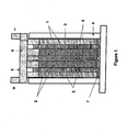
- a lead-acid battery of one embodiment of the invention suitable for testing purposes was made in the arrangement as illustrated schematically in Figures 1 and 2 .
- Two sponge lead (negative plate) electrodes (1), two lead dioxide positive plate electrodes (2) and one high surface-area negative carbon electrode plate (3) were positioned in an alternating arrangement as illustrated in Figure 1 in a battery case (4).
- the positive lead dioxide electrodes (2) and negative lead electrodes (1) were 40 millimetres wide by 68 millimetres high by 3.3 millimetres thick.
- the carbon electrode (3) was 40 millimetres wide by 68 millimetres high by 1.4 millimetres thick.
- the battery electrodes were of a standard configuration and composition for lead-acid batteries, and were made by the methods described in the detailed description above.
- the lead electrode formation techniques used in this example are more fully described in our copending application PCT/AU2003/001404 - published as WO 2004/038051 .
- the paste composition for the lead negative electrode comprised lead oxide (1kg), fibre 0.6g, BaSO 4 4.93g, Carbon black 0.26g, H 2 SO 4 (1.400 rel.dens.) 57 cm 3 , water 110 cm 3 , acid to oxide ratio 4% and paste density 4.7 g/cm 3 .
- the paste composition for the lead dioxide positive electrode comprised lead oxide 1kg, fibre 0.3g, H 2 SO 4 (1.400 rel.dens.) 57 cm 3 , water 130 cm 3 , acid to oxide ratio 4% and paste density 4.5 g/cm 3 .
- the lead oxide was converted into lead dioxide and lead by the formation techniques described in our co-pending application.
- the capacitor electrode (3) was made from 20wt% carbon black with specific surface area of 60 m 2 g (Denki Kagaku, Japan), 7.5wt% carboxymethyl cellulose, 7.5wt% neoprene, and 65wt% activated carbon with specific surface area of 2000 m 2 g -1 (Kurarekemikaru Co. Ltd. Japan).
- AGM separators were located between the adjacent electrodes. Absorptive glass microfibre (AGM) separators (5) of 2 millimetres in thickness were positioned between the lead-dioxide (2) and lead (1) electrodes, and microporous polypropylene separators (6) of 0.05 millimetres thickness were sandwiched between the positive electrodes (2) and carbon electrode (3).
- AGM Absorptive glass microfibre
- the battery case (4) was filled with sulfuric acid solution (7).
- the positive electrodes were connected to a positive busbar (8), and the negative electrodes connected to a negative busbar (9).
- the capacitor negative plate could be disconnected from the negative busbar.
- a charging and discharging profile was developed to simulate typical charge and discharge demands on a 42-volt mild HEV battery typically used in mild HEV applications.
- the profile has short duration (2.35 minutes) and is composed of several current steps that simulate the power requirements of the battery during vehicle operation. These are, in order:
- the critical step is the cranking period over which the cell must deliver a current of 17.5A for 0.5 seconds.
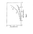
- a cut-off voltage of 1.6-volts which is a common cut-off voltage value for batteries in the field of the invention, was set, and the batteries were subjected to repetitive cycling through the charge cycle until the lowest voltage during discharge reached the cut-off value.
- line 10 is the comparison battery internal resistance profile
- line 11 is the Example 1 battery internal resistance profile
- line 12 is the comparison battery minimum discharge voltage profile
- line 13 is the Example 1 battery minimum discharge voltage profile.
- the comparison battery performs about 2150 cycles, while the battery of Example 1 performs 8940 cycles before the minimum discharge voltages of each battery reaches the cut-off value of 1.6-volts (represented by line 15.
- the cycling performance of the battery of Example 1 is at least four times better than that of the comparison battery.
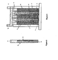
- the embodiment of this Example comprises three lead dioxide positive plate electrodes (2) and two composite negative electrodes (16).
- the composite negative electrodes comprise a current collector or grid (17) with the lead-containing paste composition described above applied to one region (the face) thereof (18) and capacitor high surface-area carbon electrode material-containing paste applied to the opposite face (19). Formation of the electrode is conducted in the manner known in the art.
- a lead based negative electrode is prepared with lead pasted by conventional dipping techniques to the main body section in lead paste material, followed by formation, and then the capacitor material is pasted to a region or regions of this lead based negative electrode, such as one face thereof.
- the positive (2) and negative composite electrodes (16) are positioned in an alternating arrangement as illustrated in Figure 5 in a battery case (4).
- the positive lead dioxide electrodes (2) and negative composite electrodes (16) of the embodiment illustrated in Figure 5 are 40 millimetres wide by 68 millimetres high by 3.3 millimetres thick.
- the carbon electrode region (19) of the negative electrode takes up 1.4 millimetres of the thickness of the negative electrode.
- AGM separators (5) of 2 millimetres in thickness are positioned between the lead-dioxide (2) and lead face (18) of the negative electrode, and microporous polypropylene separators (6) of 0.05 millimetres thickness are sandwiched between the positive electrodes (2) and carbon face of the negative electrode (19).
- AGM Absorptive glass microfibre
- the battery case (4) is filled with sulfuric acid solution (7).
- the positive electrodes are connected to a positive busbar (8), and the negative electrodes connected to a negative busbar (9).
- Example 1 Further testing on the battery of Example 1 showed that improvements in electrolyte dry-out could be achieved by matching the hydrogen evolution rate of the carbon electrode (3) during battery charging to be similar to that of the lead negative electrode (1). This was achieved by replacing the carbon electrode of Example 1 with a modified carbon electrode (103) with 2.5 wt% PbO and 2.5 wt% ZnO, 65 wt% activated carbon, 20 wt% carbon black and binder (10 wt%) in the paste composition.
- a modified carbon electrode (103) with 2.5 wt% PbO and 2.5 wt% ZnO, 65 wt% activated carbon, 20 wt% carbon black and binder (10 wt%) in the paste composition.
- FIG. 8 A further variation on the battery of Example 1 is illustrated in Figure 8 .
- the same numerals are used to refer to common features of the two batteries.
- the battery electrodes are illustrated.
- the battery further includes the separators, case, electrolyte, busbars, terminals and other features of batteries common in the art.
- the battery of this Example comprises an alternating series of positive and negative electrodes.
- the electrodes are, in order from left to right, a lead dioxide battery positive electrode (2), a lead-based battery negative electrode (3), a second lead dioxide battery positive electrode (2), a capacitor carbon and additive negative electrode of the type described in Example 3 (103), a capacitor-battery positive electrode as described further below (23), a second capacitor carbon and additive negative electrode of the type described in Example 3 (103), a second lead based battery negative electrode (3) and a third lead dioxide battery positive electrode (2).
- Each of the positive and negative electrodes, respectively, are connected to a positive conductor and a negative conductor, and to the positive and negative terminals of the battery.
- the capacitor-battery electrode (23) comprises a metal current collector, with a mixture of activated carbon (60 wt%), carbon black (20 wt%) and 10 wt% of lead oxide pasted thereon.
- the paste composition is formed with 10 wt% [5 wt% carboxymethyl cellulose and 5 wt% neoprene] binder and sintered onto the current collector.
- the electrode is about 0.8 mm thick. In gassing tests it was shown that the inclusion of SbO and red lead in this capacitor positive electrode has an advantageous effect on gassing, and therefore these additives may further be contained in the capacitor positive electrode.
- the battery of this Example can contain further alternating positive and negative electrodes of any type. Generally it is desirable to ensure that there is some level of matching the surface areas and hydrogen gassing rates of the sum of the positive and negative electrodes, and to include the requisite number of positive and negative electrodes to provide a battery of the desired voltage.
Abstract
Description
- The present invention relates to high performance as lead-acid batteries.
- There is growing demand for the development and introduction of vehicles that do not rely almost entirely on fossil fuels, to combat air pollution in urban environments and to reduce the global consumption of limited supplies of the fossil fuels. Such vehicles fall into three main classes: electric vehicles (EVs), hybrid electric vehicles (HEVs) and mild hybrid electric vehicles (also known as 42-volt powernet vehicles).
- Electric vehicles and hybrid electric vehicles may use a variety of different battery types, including lead-acid batteries. Mild hybrid electric vehicles may use mainly lead-acid batteries because of reduced cost. Hybrid and mild hybrid electric vehicles rely on a combination of an internal combustion engine and a battery for power supply. Due to the increasing on-board power requirements in the present luxury cars (internal combustion engine cars), the capability of present 14-volt alternators is close to or beyond its limitation. Thus, mild hybrid electric vehicles have been developed. Such mild hybrid electric vehicles employ a 36-volt battery and a 42-volt alternator. The mild hybrid electric vehicles provide some advantages over the existing internal combustion engine cars, including higher use of the electrically generated power, resulting in lower emissions.
- Whilst there have been many significant advances in the development of new batteries and power networks for vehicles relying at least partly on electric power, the batteries used in these vehicles still suffer from a number of problems.
- In all of these batteries, different demands are placed on the battery in terms of the current drawn from and recharged to the battery at various stages during vehicle operation. For example, a high rate of discharge is needed from the battery to enable acceleration or engine cranking in electric and hybrid electric vehicles, respectively. A high rate of recharging of the battery is associated with regenerative braking.
- In the situation where lead-acid batteries are utilised, particularly in hybrid and mild hybrid electric vehicles, the high rate of battery discharging and recharging results in the formation of a layer of lead sulphate on the surface of the negative plate, and the generation of hydrogen/oxygen at the negative and positive plates. This largely arises as a result of high current demands on the battery. The partial state-of-charge conditions (PSoC) under which these batteries generally operate is 20-100% for electric vehicles, 40-60% for hybrid electric vehicles, and 70-90% for mild hybrid electric vehicles. This is a high rate partial state-of-charge (HRPSoC). Under simulated HRPSoC duty, such as hybrid and mild hybrid electric vehicle operations, the lead-acid batteries fail prematurely mainly due to the progressive accumulation of lead sulphate on the surfaces of the negative plates. This occurs because the lead sulphate cannot be converted efficiently back to sponge lead during charging either from the regenerative braking or from the engine. Eventually, this layer of lead sulphate develops to such an extent that the effective surface area of the plate is reduced markedly, and the plate can no longer deliver the higher current demanded from the automobile. This significantly reduces the potential life span of the battery.
- In other technology fields, including mobile or cell phone technology, it would be advantageous to provide alternative battery types that offer improved overall lifespan and performance whilst catering for the different power demands on the device.
- Accordingly, there exists a need for modified batteries, including lead-acid batteries, that have an improved life span and/or improved overall performance compared to current batteries.
- According to the present invention there is provided a lead-acid battery comprising:
- at least one lead-based negative electrode;
- at least one lead dioxide-based positive electrode;
- at least one capacitor electrode; and
- electrolyte in contact with the electrodes;
- According to this aspect, each of the capacitor electrodes may individually be positive or negative electrodes.
- In one embodiment, the capacitor electrode is a capacitor negative electrode. In this embodiment, the lead dioxide battery part and the asymmetric capacitor part of the lead-acid battery are connected in parallel in the one common unit. Hence, the asymmetric capacitor part preferentially takes or releases charge during high current charging or discharging. This occurs since the asymmetric capacitor part has a lower internal resistance than the battery-part, and will first absorb and release charge during high-rate charging (for instance during regenerative braking) or during high-rate discharging (for instance during vehicle acceleration and engine cranking). Consequently, the asymmetric capacitor part will share the high-rate operation of the lead-acid battery part, and will provide the lead-acid battery with significantly longer life. All of this is achieved without any electronic control or switching between the battery and capacitor parts.
- According to one embodiment, the positive electrode shared by the two parts is disposed between the lead-based negative electrode and the capacitor negative electrode.
- It will be appreciated that the reverse arrangement may be utilised, in which the shared electrode is the lead-based negative electrode. The lead-based negative electrode will define an asymmetric capacitor part with a capacitor positive electrode.
- Preferably, the lead-acid battery comprises an alternating series of positive and negative electrodes. Of the alternating electrodes, each of these may be a battery electrode, a capacitor electrode, or a combined battery/capacitor electrode. These electrode types will be described in further detail below.
- In a further feature of the invention, it has been found that if there is a mismatch in the potential window or potential operational range of one of the electrodes, hydrogen gassing may occur. This particularly applies when the cell voltage is greater than the potential range of an electrode. Hydrogen gassing is undesirable as it leads to premature failure of the battery at the electrode where gassing occurs.
- To avoid a mismatch, according to a further embodiment, at least one of the capacitor negative electrodes comprises a high surface area capacitor material and one or more additives selected from oxides, hydroxides or sulfates of lead, zinc, cadmium, silver and bismuth. The additives are preferably added in oxide form. The additives are preferably lead and/or zinc additives, most preferably lead and/or zinc oxide.
- Mismatching can also occur at the capacitor positive electrode. Thus, according to one embodiment in which the battery comprises a capacitor positive electrodes, the capacitor positive electrode comprises:
- a high surface area capacitor material,
- Pb2O3,
- an oxide, hydroxide or sulfate of antimony, and
- optionally one or more additives selected from oxides, hydroxides and sulfates of iron and lead.
- According to a further feature of the invention, there is also disclosed novel capacitor electrodes based on the above concept. The novel capacitor negative electrode comprises a current collector and a paste coating, the paste coating comprising a high surface area capacitor material, a binder and between 5-40wt%, based on the weight the paste coating, of an additive or additive mixture selected from oxides, hydroxides or sulfates of lead, zinc, cadmium, silver and bismuth, with the proviso that the additive includes at least one oxide, hydroxide or sulfate of lead or zinc.
- The novel capacitor positive electrode comprises a current collector and a paste coating, the paste coating comprising a high surface area capacitor material, a binder and between 10-40wt%, based on the weight the paste coating, of an additive mixture comprising:
- Pb2O3,
- an oxide, hydroxide or sulfate of antimony, and
- optionally one or more oxides, hydroxides or sulfates of iron and lead.
-
-
Figure 1 is a schematic side view of a lead-acid battery in accordance with one embodiment of the invention; -
Figure 2 is a schematic plan view of the lead-acid battery ofFigure 1 ; -
Figure 3 is a graph representing a current profile of a single cycle of the test conducted on the battery of the embodiment ofFigures 1 and2 ; -
Figure 4 is a graph representing the cycling performance of the battery ofFigures 1 and2 against a comparison battery; -
Figure 5 is a schematic side view of a lead-acid battery in accordance with a second embodiment of the invention; -
Figure 6 is a schematic side view of one of the negative electrodes of the lead-acid battery ofFigure 5 ; -
Figure 7 is a graph representing the hydrogen evolution rate of a negative capacitor electrode of a fourth embodiment of the invention, compared to a standard carbon electrode and a standard lead-based negative electrode; -
Figure 8 is a schematic side view representing the electrode arrangement of a battery of a third embodiment of the invention. - The present invention will now be described in further detail with reference to preferred embodiments of the invention.
- To avoid any doubt, except where the context requires otherwise due to express language or necessary implication, the word "comprise" or variations such as "comprises" or "comprising" is used in an inclusive sense, i.e. to specify the presence of the stated features but not to preclude the presence or addition of further features in various embodiments of the invention.
- The term "lead-acid battery" is used in its broadest sense to encompass any unit containing one or more lead-acid battery cells.
- The lead-acid batteries described contain at least one lead-based negative electrode or region, at least one lead dioxide-based positive electrode or region and at least one capacitor negative electrode or region.
- In the following each of these electrode types are described, followed by the electrode region concept.
- Electrodes generally comprise a current collector (otherwise known as a grid or plate), with the active electrode material applied thereto. The active electrode material is most commonly applied in a paste form to the current collector, and in the present specification the term paste applies to all such active-material containing compositions applied in any way to the current collector. The term "based" used in the context of electrodes is intended to refer to the active electrode material. This term is used to avoid suggesting that the electrode is formed entirely from the active material, as this is not the case. The term also is intended to indicate that the active material of the given electrode may contain additives or materials other than the active material specifically mentioned.
- The lead and lead dioxide electrodes may be of any arrangement or type suitable for use in a lead-acid battery. Generally, such electrodes are in the form of a metal grid (usually made from lead or lead alloy) that supports the electrochemically active material (lead or lead dioxide) which is pasted onto the grid. The operation of pasting is well known in the field. Although any suitable lead or lead dioxide known in the art may be used, it would be advantageous to use the lead compositions disclosed in co-pending application
PCT/AU2003/001404 AU 2002952234 WO 2004/038051 . It is to be noted that, prior to formation of the battery, the active material may not be in the active form (i.e. it may not be in the form of the metal, or in the dioxide form). Thus, the terms encompass those other forms which are converted to lead metal or lead dioxide when the battery is formed. - Capacitor electrodes similarly comprise a current collector and a coating of an active material. This is commonly applied as a paste.
- The term "capacitor" is used in the context of electrodes to refer to electrodes that store energy through the double layer capacitance of a particle/solution interface between high surface area materials and an electrolyte solution.
- There are two main classes of capacitors. One class is the "double-layer capacitors" (otherwise known as "symmetric capacitors") containing two such electrodes, one as the positive and the other as the negative. The second class is the asymmetric capacitors, which are also referred to as hybrid capacitors, "ultracapacitors" and "supercapacitors".
- Asymmetric capacitors comprise one electrode that stores energy through double layer capacitance across a particle/solution interface, and a second electrode that is a faradaic or battery-type electrode which stores energy pseudocapacitively. The prefixes "ultra" and "super" are sometimes used to refer generically to asmymmetric capacitors, and sometimes to refer to such capacitors having large storage capability. In the present application the prefix "ultra" is most usually used in this first sense, but on occasion it is used in the second sense, as the capacitance of the capacitor parts of the batteries of the present invention preferably have high capacitance. The asymmetric capacitor parts preferably have ultracapacitor capacitance, more preferably of supercapacitor capacitance.
- Generally, as with the lead and lead oxide electrodes, the capacitor electrode comprises a metal grid (usually made from a lead alloy) and a pasted coating containing the capacitor material, usually with a binder. Examples of a suitable binders for the paste compositions are carboxymethyl cellulose and neoprene.
- The capacitor electrode suitably comprises a high surface area (or high-rate) materials suitable for use in capacitors. Such materials are well known in the art. These high-rate capacitor materials include high surface area carbon, ruthenium oxide, silver oxide, cobalt oxide and conducting polymers. Preferably, the capacitor negative electrode comprises a high surface area carbon material. Examples of high surface area carbon materials are activated carbon, carbon black, amorphous carbon, carbon nanoparticles, carbon nanotubes, carbon fibres and mixtures thereof.
- Often mixtures of materials are used to obtain an appropriate balance between surface area (and thus capacitance) and conductivity. Currently, for cost reasons, activated carbon is the most appropriate source. One suitable activated carbon material is one with a surface area of between 1000 and 2500 m2/g, preferably 1000-2000 m2/g. This material is suitably used in combination with a more conductive material, such as carbon black. One suitable carbon black material has a surface area of between 60-1000 m2/g. One suitable mixture of these materials comprises between 5-20% carbon black, 40-80% activated carbon, 0-10% carbon fibres, and the balance binder at a level of between 5-25%. All measurements are by weight unless specified otherwise.
- As described above, it has been found that if there is a mismatch in the potential window or potential operational range of one of the electrodes, hydrogen and/or oxygen gassing may occur. According to one embodiment, to suppressing hydrogen gassing, the capacitor negative electrodes comprise an additive or additive mixture comprising an oxide, hydroxide or sulfate of lead, zinc, cadmium, silver and bismuth, or a mixture thereof. Generally, it is preferred that the additive includes at least one oxide, hydroxide or sulfate of lead or zinc. For convenience, the additive is suitably one or more oxides selected from lead oxide, zinc oxide, cadmium oxide, silver oxide and bismuth oxide. Preferably each of the capacitor negative electrodes comprise the additive in addition to the high surface area capacitor material. Due to toxicity reasons, cadmium compounds are not preferred, and therefore the composition preferably comprises a lead compound and/or zinc compound, and optionally a silver compound. For cost reasons, silver oxide and bismuth oxide would usually be avoided.
- Irrespective of the form in which the additive is added, when conductor comes into contact with the sulfuric acid electrolyte, the additive may react with the electrolyte and thus be converted into another metal compound derived from the original metal oxide, sulfate or hydroxide. References to the oxides, sulfates and hydroxides of the subject additives are to be read as encompassing the products of the reactions between the additives and the electrolyte. Similarly, if during the charged or discharged state of the battery the additive is converted into another form through redox reactions, the references to the oxides, sulfates and hydroxides are to be read as encompassing the products of the redox reactions on these additives.
- To suppress oxygen gassing, the capacitor positive electrodes preferably comprises:
- a high surface area capacitor material (as described above),
- Pb2O3 ("red lead"),
- an oxide, hydroxide or sulfate of antimony, and
- optionally one or more additives selected from oxides, hydroxides and sulfates of iron and lead.
- The compound of antimony is beneficial in suppressing (oxygen) gassing at the positive capacitor electrode. However, if it migrates to the negative capacitor electrode, it produces an adverse effect on hydrogen gassing at that electrode. In the absence of an agent to fix the antimony compound to the positive capacitor electrode, when the antimony compound comes into contact with the electrolyte, it may dissolve in the electrolyte, and be deposited on the negative electrode when a current is applied. The red lead is used to fix or prevent transfer of the antimony to the negative electrode. Compounds (i.e. oxides, sulfates or hydroxides) of lead and iron are also advantageous in this electrode, and may also be used in the additive mixture.
- In each case, the additive is used in amount to avoid hydrogen and oxygen gassing. This is generally an amount that increases the potential window of the capacitor negative and positive electrode from the typical ±0.9V or ±1.0V to at least ±1.2V, and preferably at least +1.3V. In general terms, the total oxide content may be between 5-40wt%, based on the total active material composition (including high surface active material, binder, and any other component in the dried paste composition).
- Preferably, the negative capacitor electrode additive comprises between 1-40wt% Pb compound (more preferably 1-20%), 1-20wt% Zn compound (more preferably 1-10%), 0-5wt% Cd compound and 0-5wt% Ag compound. Preferably the total is within the 5-40wt% range mentioned above. The use of ZnO additive alone provides good results, as does PbO alone, or a mixture of PbO and ZnO.
- Preferably, the positive capacitor electrode additive comprises between 0-30wt% Pb (preferably 1-30wt%) in oxide (any oxide), sulfate or hydroxide form, 1-10wt% Pb2O3, 0-2wt% Fe (preferably 1-2wt%) in oxide, sulfate or hydroxide form and 0.05 to 1wt% Sb in oxide, sulfate or hydroxide form. Preferably Sb is added as an oxide. Preferably the total is within 5-40wt% range mentioned above.
- As described in further detail below, the battery may include electrodes of other types in addition to or as a replacement of the electrodes described above. In particular, the battery may comprise one or more mixed capacitor-battery electrodes, such as a capacitor-battery positive electrode.
- In the situation where the capacitor positive electrode (as described above) comprises lead oxide, this is converted into lead dioxide during charging of the battery. Thus, the capacitor electrode comprising a lead source which is converted into lead dioxide in operation of the battery may be considered to be a capacitor-battery electrode having some qualities of both a capacitor electrode and a battery electrode.
- The incorporation of high surface area material such as carbon into some positive electrodes may be undertaken to address the need to balance the surface area ratio of the positive to negative electrodes. In the absence of any capacitor positive electrodes, the high surface area capacitor negative electrodes will add to a greater overall surface area for negative electrodes compared to positive electrodes. When there is a surface area imbalance, failure of the lower surface area electrodes. By making the surface area of the positive electrode greater, by incorporating high surface area carbon into some positive electrodes, the balance is addressed.
- As a consequence of the above, it will be appreciated to persons in the art that the battery may comprise an alternating series of positive and negative electrodes, with an electrolyte in contact with the electrodes, and a first conductor for directly connecting the positive electrodes and a second conductor for directly connecting the negative electrodes, wherein at least one pair of the adjacent positive and negative electrode regions form a capacitor (by storing capacitive energy), and at least one pair of adjacent positive and negative electrode regions form a battery (by storing energy as electrochemical potential between the two electrode pairs).
- The electrodes of the present invention may be composite electrodes (i.e. they may be composites of battery electrode materials and capacitor electrode materials). The references to "lead-based", "lead dioxide-based" and "capacitor" electrodes encompass the regions of an electrode that have the specified function, irrespective of whether or not the single electrode has other regions of a different type.
- According to one embodiment of the invention, electrodes having regions of different types are deliberately used. According to this embodiment, one or more of the negative electrodes has at least two regions, including a battery-electrode material region and a capacitor-electrode material region. As one example, the electrode having two regions comprises an electrode current collector, which may be of the type described above, having one face pasted with battery electrode material (such as lead) and the opposite face pasted with capacitor negative electrode material. Alternatively, a battery-type electrode containing battery electrode material on both sides may be coated on one face or any other region thereof by a capacitor electrode material.
- The electrodes may be of any suitable shape, and therefore may be in flat-plate form or in the form of a spirally-wound plate for the formation of either prismatic or spirally-wound cells. For simplicity of design, flat plates are preferred.
- In the case of lead-acid batteries, sulphuric acid electrolyte is used. The electrolyte may, for instance, be in the form of a liquid or a gel.
- The busbar of the lead-acid battery may be of any suitable construction, and may be made from any suitable conductive material known in the art. The term "connected to" used in the context of the busbars refers to electrical connection, although direct physical contact is preferred. In the case where the battery is not of a typical lead-acid battery configuration with busbars, any conductor may be used that does not involve circuitry external to the battery.
- Generally, the components of the battery will be contained within a battery case with further features appropriate to the type of battery employed. For example, the lead-acid battery may be either of a flooded-electrolyte design or of a valve-regulated design. Where the lead-acid battery is a valve-regulated lead-acid battery, the battery may be of any suitable design, and may for instance contain gel electrolyte. Specific features of the battery unit appropriate to such designs are well known in the art of the invention.
- The pressure that may be applied to the lead-acid battery may lie in the range of 5-20 kPa for flooded electrolyte design, and from 20-80 kPa for valve regulated lead-acid battery design.
- Generally, each of the positive and negative electrodes is separated from adjacent electrodes by porous separators.
- The separators maintain an appropriate separation distance between adjacent electrodes. Separators located between immediately adjacent lead-based negative electrodes and lead dioxide-based positive electrodes may be made from any suitable porous material commonly used in the art, such as porous polymer materials or absorptive glass microfibre ("AGM"). The separation distance (corresponding to separator thickness) is generally from 1-2.5 millimetres for these separators. Suitable polymer materials useful for forming the separators between the positive and negative electrodes forming the battery part are polyethylene and AGM. Polyethylene separators are suitably between 1 and 1.5 millimetres thick, whereas AGM separators are appropriately between 1.2 and 2.5 millimetres thick.
- In the case of separators located between the positive electrode and the capacitor negative electrode, these are suitably much thinner than the separators of the battery part of the lead-acid battery. Advantageously, the separators are between 0.01 and 0.1 millimetres thick, and most preferably between 0.03 and 0.07 millimetres thick. These separators are suitably made from microporous polymer material such as microporous polypropylene. Other separators are AGM and the thickness of this type of separators is between 0.1 and 1 millimetres, and preferably between 0.1 and 0.5 millimetres.
- After assembling of the appropriate components together in a battery case, the lead-acid battery generally needs to be formed. The formation operation is well known in the field. It is to be understood that the references to "lead-based" and "lead dioxide-based" materials are used to refer to lead or lead dioxide itself, materials containing the metal/metal dioxide or to materials that are converted into lead or lead dioxide, as the case may be, at the given electrode.
- As is indicated by the language used above, the lead-acid battery contains at least one of each type of electrode. The number of individual cells (made up of a negative and positive plate) in the battery depends on the desired voltage of each battery. For a 36-volt battery appropriate for use as a mild hybrid electric vehicle battery (which may be charged up to 42 volt), this would involve the use of 18 cells.
- For best operation according to one embodiment, the positive and negative electrodes are interleaved, so that each positive electrode has one lead-based negative electrode to one side of it, and one capacitor negative electrode to the opposite side. Accordingly, the arrangement of one embodiment has alternating positive and negative electrodes, with the negative electrodes being alternately a lead-based electrode and a capacitor negative electrode. All of the negative electrodes (lead and carbon) are connected to the negative busbar, and the positive electrodes are connected to the positive busbar, so that each battery cell and ultracapacitor cell is connected in parallel in the common lead-acid battery.
- As explained above, the ultracapacitor cell in the lead-acid battery arrangement described has a lower internal resistance than the lead-acid battery cell, and therefore it will first absorb a release charge during high-rate charging (for generative braking) or during high-rate discharge (vehicle acceleration and engine cranking). Consequently, the asymmetric capacitor cell will share the high-rate operation of the lead-acid battery cell and will provide the lead-acid battery with significantly longer life. More specifically, lead sulphate formation on the battery cell electrodes which generally occurs during high-current charging and discharging of the battery is minimised because the high-current charging and discharging is generally taken up by the asymmetric capacitor.
- Each battery cell of one embodiment of the invention provides a voltage of 2-volts. A lead-acid battery of one embodiment suitable for use in the broad range of electric vehicle battery applications will contain 8 negative electrodes and 9 positive electrodes, with 4 of the negative electrodes being lead-based negative electrodes, and the other 4 being capacitor electrodes, in an alternating arrangement. Variations in this arrangement and relative numbers of electrodes are also suitable, provided that there is a minimum of one of each electrode.
- A lead-acid battery of one embodiment of the invention suitable for testing purposes was made in the arrangement as illustrated schematically in
Figures 1 and2 . - Two sponge lead (negative plate) electrodes (1), two lead dioxide positive plate electrodes (2) and one high surface-area negative carbon electrode plate (3) were positioned in an alternating arrangement as illustrated in
Figure 1 in a battery case (4). The positive lead dioxide electrodes (2) and negative lead electrodes (1) were 40 millimetres wide by 68 millimetres high by 3.3 millimetres thick. The carbon electrode (3) was 40 millimetres wide by 68 millimetres high by 1.4 millimetres thick. The battery electrodes were of a standard configuration and composition for lead-acid batteries, and were made by the methods described in the detailed description above. The lead electrode formation techniques used in this example are more fully described in our copending applicationPCT/AU2003/001404 WO 2004/038051 . In brief, the paste composition for the lead negative electrode comprised lead oxide (1kg), fibre 0.6g, BaSO4 4.93g, Carbon black 0.26g, H2SO4 (1.400 rel.dens.) 57 cm3, water 110 cm3, acid to oxide ratio 4% and paste density 4.7 g/cm3. The paste composition for the lead dioxide positive electrode comprised lead oxide 1kg, fibre 0.3g, H2SO4 (1.400 rel.dens.) 57 cm3, water 130 cm3, acid to oxide ratio 4% and paste density 4.5 g/cm3. The lead oxide was converted into lead dioxide and lead by the formation techniques described in our co-pending application. - The capacitor electrode (3) was made from 20wt% carbon black with specific surface area of 60 m2 g (Denki Kagaku, Japan), 7.5wt% carboxymethyl cellulose, 7.5wt% neoprene, and 65wt% activated carbon with specific surface area of 2000 m2 g-1 (Kurarekemikaru Co. Ltd. Japan).
- Separators (5, 6) were located between the adjacent electrodes. Absorptive glass microfibre (AGM) separators (5) of 2 millimetres in thickness were positioned between the lead-dioxide (2) and lead (1) electrodes, and microporous polypropylene separators (6) of 0.05 millimetres thickness were sandwiched between the positive electrodes (2) and carbon electrode (3).
- The battery case (4) was filled with sulfuric acid solution (7). The positive electrodes were connected to a positive busbar (8), and the negative electrodes connected to a negative busbar (9). As noted below, for comparison purposes, for simulation of a battery containing no ultracapacitor cell component, the capacitor negative plate could be disconnected from the negative busbar.
- For testing purposes, a charging and discharging profile was developed to simulate typical charge and discharge demands on a 42-volt mild HEV battery typically used in mild HEV applications. The profile has short duration (2.35 minutes) and is composed of several current steps that simulate the power requirements of the battery during vehicle operation. These are, in order:
- (a) an idle stop section involving a discharge of 2A over a 60 second period;
- (b) a high current discharge of 17.5A, lasting 0.5 seconds, simulating cranking;
- (c) an 8.5A power assistance discharge of 0.5 seconds;
- (d) a 14-volt/2A maximum, 70 second long engine charging section simulating charging of the battery during standard driving conditions;
- (e) a 5 second rest period; and
- (f) a 14-volt/2A maximum period correlating to regenerative charging (regenerative braking) lasting 5 seconds.
- The critical step is the cranking period over which the cell must deliver a current of 17.5A for 0.5 seconds.
- To test the life span of the battery of the example, two identical batteries were made, and one was thereafter modified to disconnect the capacitor carbon negative electrode from the negative busbar, to correspond to an equivalent battery without the integral ultracapacitor feature, hereafter referred to as the "comparison battery".
- Each battery was subjected to repeated cycles of the profile illustrated in
Figure 3 and described above. A cut-off voltage of 1.6-volts, which is a common cut-off voltage value for batteries in the field of the invention, was set, and the batteries were subjected to repetitive cycling through the charge cycle until the lowest voltage during discharge reached the cut-off value. - The results of the test are illustrated in
Figure 4 . In this figure,line 10 is the comparison battery internal resistance profile,line 11 is the Example 1 battery internal resistance profile,line 12 is the comparison battery minimum discharge voltage profile andline 13 is the Example 1 battery minimum discharge voltage profile. - During cycling, the following observations were made:
- (i) the maximum charge voltages of the comparison battery and the battery of Example 1 are maintained at 2.35-volts, as represented by
line 14. - (ii) the internal resistances of both batteries increase with cycling. Nevertheless, the internal resistance of the comparison battery increases faster than that of the battery of Example 1, for example, from 19 to 25 mΩ for the comparison battery and from 18 to 25 mΩ for the battery of Example 1.
- (iii) The minimum discharge voltages of the comparison battery and the battery of Example 1 decrease with cycling, but the rate of decrease is faster for the comparison battery.
- The comparison battery performs about 2150 cycles, while the battery of Example 1 performs 8940 cycles before the minimum discharge voltages of each battery reaches the cut-off value of 1.6-volts (represented by
line 15. Thus, the cycling performance of the battery of Example 1 is at least four times better than that of the comparison battery. - A variation on the battery of Example 1 is illustrated in
Figures 5 and 6 . For ease of comparison, the same numerals are used to refer to common features of the two batteries. - The embodiment of this Example comprises three lead dioxide positive plate electrodes (2) and two composite negative electrodes (16). The composite negative electrodes comprise a current collector or grid (17) with the lead-containing paste composition described above applied to one region (the face) thereof (18) and capacitor high surface-area carbon electrode material-containing paste applied to the opposite face (19). Formation of the electrode is conducted in the manner known in the art. In a variation on this embodiment that is simpler to manufacture, a lead based negative electrode is prepared with lead pasted by conventional dipping techniques to the main body section in lead paste material, followed by formation, and then the capacitor material is pasted to a region or regions of this lead based negative electrode, such as one face thereof. The positive (2) and negative composite electrodes (16) are positioned in an alternating arrangement as illustrated in
Figure 5 in a battery case (4). - The positive lead dioxide electrodes (2) and negative composite electrodes (16) of the embodiment illustrated in
Figure 5 are 40 millimetres wide by 68 millimetres high by 3.3 millimetres thick. The carbon electrode region (19) of the negative electrode takes up 1.4 millimetres of the thickness of the negative electrode. - Separators (5, 6) are located between the adjacent electrodes. Absorptive glass microfibre (AGM) separators (5) of 2 millimetres in thickness are positioned between the lead-dioxide (2) and lead face (18) of the negative electrode, and microporous polypropylene separators (6) of 0.05 millimetres thickness are sandwiched between the positive electrodes (2) and carbon face of the negative electrode (19).
- The battery case (4) is filled with sulfuric acid solution (7). The positive electrodes are connected to a positive busbar (8), and the negative electrodes connected to a negative busbar (9).
- Further testing on the battery of Example 1 showed that improvements in electrolyte dry-out could be achieved by matching the hydrogen evolution rate of the carbon electrode (3) during battery charging to be similar to that of the lead negative electrode (1). This was achieved by replacing the carbon electrode of Example 1 with a modified carbon electrode (103) with 2.5 wt% PbO and 2.5 wt% ZnO, 65 wt% activated carbon, 20 wt% carbon black and binder (10 wt%) in the paste composition.
- The hydrogen evolution rates for this electrode were tested and compared to the electrode used in Example 1, as well as the hydrogen evolution rates of the lead negative electrode of example 1. The results are shown in
Figure 7 , in which curve 20 represents the carbon electrode hydrogen evolution rate,curve 21 represents the lead-acid negative plate hydrogen evolution rate, and the curve 22 represents the carbon plus additives electrode hydrogen evolution rate. The higher current density levels recorded for the carbon electrode with no oxide additive rise considerably at potentials falling below -1.2V, and even more so by -1.3V. By more closely matching the hydrogen evolution rate of the two electrodes, the battery can be operated at higher potentials without earlier failure due to electrolyte dry-out. - Inclusion of the oxide CdO would have a similar effect to ZnO and PbO, but for toxicity reasons was not used in the testing. AgO has a similar effect, but is an expensive additive and not as effective on its own. In other tests the levels of ZnO and PbO were varied within the range 1-10% and 1-20% respectively, and the AgO between 1-5%. The other oxides mentioned in the detailed description above have a similar impact to AgO.
- A further variation on the battery of Example 1 is illustrated in
Figure 8 . For ease of comparison, the same numerals are used to refer to common features of the two batteries. In addition, for simplicity, only the battery electrodes are illustrated. It will be understood that the battery further includes the separators, case, electrolyte, busbars, terminals and other features of batteries common in the art. - The battery of this Example comprises an alternating series of positive and negative electrodes. The electrodes are, in order from left to right, a lead dioxide battery positive electrode (2), a lead-based battery negative electrode (3), a second lead dioxide battery positive electrode (2), a capacitor carbon and additive negative electrode of the type described in Example 3 (103), a capacitor-battery positive electrode as described further below (23), a second capacitor carbon and additive negative electrode of the type described in Example 3 (103), a second lead based battery negative electrode (3) and a third lead dioxide battery positive electrode (2). Each of the positive and negative electrodes, respectively, are connected to a positive conductor and a negative conductor, and to the positive and negative terminals of the battery.
- The capacitor-battery electrode (23) comprises a metal current collector, with a mixture of activated carbon (60 wt%), carbon black (20 wt%) and 10 wt% of lead oxide pasted thereon. The paste composition is formed with 10 wt% [5 wt% carboxymethyl cellulose and 5 wt% neoprene] binder and sintered onto the current collector. The electrode is about 0.8 mm thick. In gassing tests it was shown that the inclusion of SbO and red lead in this capacitor positive electrode has an advantageous effect on gassing, and therefore these additives may further be contained in the capacitor positive electrode.
- The battery of this Example can contain further alternating positive and negative electrodes of any type. Generally it is desirable to ensure that there is some level of matching the surface areas and hydrogen gassing rates of the sum of the positive and negative electrodes, and to include the requisite number of positive and negative electrodes to provide a battery of the desired voltage.
Claims (14)
- A lead-acid battery comprising an alternating series of positive and negative electrodes and an electrolyte in contact with the electrodes, characterized in that:at least one pair of positive and negative electrodes or electrode regions store energy capacitively and one of said electrodes or regions comprises capacitor electrode material,at least one pair of lead dioxide positive and lead negative battery electrodes or electrode regions store energy electrochemically, andthe electrolyte is sulfuric acid,and the positive electrodes are directly connected by a first conductor and the negative electrodes are directly connected by a second conductor.
- The lead-acid battery of claim 1, characterized in that:at least one negative electrode is a lead-based negative electrode;at least one positive electrode is a lead-dioxide positive electrode;at least one of the positive or negative electrodes is a capacitor electrode; andthe regions that store energy electrochemically are formed by the lead based negative electrode and the lead dioxide-based positive electrode; andthe regions that store energy capacitively are the capacitor electrode and one electrode selected from the lead based negative electrode and the lead-dioxide based positive electrode.
- The lead-acid battery of claim 1 or claim 2, wherein the capacitor electrode material comprises a high surface area material selected from carbon, ruthenium oxide, silver oxide, cobalt oxide and conducting polymers.
- The lead-acid battery of claim 3, wherein the high surface area material is a high surface area carbon material.
- The lead-acid battery of claim 4, wherein the high surface area carbon material is selected from activated carbon, carbon black, amorphous carbon, carbon nanoparticles, carbon nanotubes and carbon fibres.
- The lead-acid battery of claim 4, wherein the carbon black has a surface area between 60-1000m2/g and the activated carbon has a surface area between 1000-2500m2/g.
- The lead-acid battery of any one of claims 1 to 5, wherein the lead-acid battery comprises at least one negative electrode or region comprising a capacitor electrode material that is a high surface area capacitor material and an additive being a capacitor negative electrode additive comprising an oxide, hydroxide or sulfate of lead, zinc, cadmium, silver or bismuth, or a mixture thereof.
- The lead-acid battery of claim 7, wherein the total capacitor negative electrode additive content is between 5-40wt%, based on the total capacitor electrode material.
- The lead-acid battery of claim 7 or claim 8, wherein the capacitor negative electrode additive comprises the compounds of the following metals in oxide, sulfate or hydroxide form: between 1-40wt% Pb; 1-20wt% Zn; 0-5wt% Cd and 0-5wt% Ag.
- The lead-acid battery of any one of claims 1 to 9, wherein the lead-acid battery comprises at least one positive electrode or region comprising a capacitor electrode material that is a high surface area capacitor material, and an additive being a capacitor positive electrode additive comprising:Pb2O3,an oxide, hydroxide or sulfate of antimony, andoptionally one or more additives selected from oxides, hydroxides and sulfates of iron and lead.
- The lead-acid battery of claim 10, wherein the total capacitor positive electrode additive is between 5-40wt%, based on the total capacitor electrode material.
- The lead-acid battery of claim 10 or claim 11, wherein the capacitor positive electrode additive comprises between 0-30wt% Pb in oxide, sulfate or hydroxide form, 1-10wt% Pb2O3, 0-2wt% Fe in oxide, sulfate or hydroxide form and 0.05 to 1wt% Sb in oxide, sulfate or hydroxide form.
- The lead-acid battery of any one of claims 1 to 12, wherein the lead-acid battery comprises a negative electrode with at least two regions, including a battery-electrode material region and a capacitor-electrode material region.
- The lead-acid battery of claim 13, wherein the negative electrode comprises a lead-based battery electrode material region on one face, and a capacitor negative electrode material region on the opposite face.
Priority Applications (1)
| Application Number | Priority Date | Filing Date | Title |
|---|---|---|---|
| PL10012505T PL2290737T3 (en) | 2003-09-18 | 2004-09-16 | High performance energy storage devices |
Applications Claiming Priority (2)
| Application Number | Priority Date | Filing Date | Title |
|---|---|---|---|
| AU2003905086A AU2003905086A0 (en) | 2003-09-18 | High performance lead-acid battery | |
| EP04761297A EP1665446B1 (en) | 2003-09-18 | 2004-09-16 | High performance energy storage devices |
Related Parent Applications (2)
| Application Number | Title | Priority Date | Filing Date |
|---|---|---|---|
| EP04761297.3 Division | 2004-09-16 | ||
| EP04761297A Division EP1665446B1 (en) | 2003-09-18 | 2004-09-16 | High performance energy storage devices |
Publications (3)
| Publication Number | Publication Date |
|---|---|
| EP2290737A2 EP2290737A2 (en) | 2011-03-02 |
| EP2290737A3 EP2290737A3 (en) | 2011-07-20 |
| EP2290737B1 true EP2290737B1 (en) | 2015-03-11 |
Family
ID=34280538
Family Applications (3)
| Application Number | Title | Priority Date | Filing Date |
|---|---|---|---|
| EP10012505.3A Active EP2290737B1 (en) | 2003-09-18 | 2004-09-16 | High performance energy storage devices |
| EP10012506.1A Active EP2273602B1 (en) | 2003-09-18 | 2004-09-16 | High performance energy storage devices |
| EP04761297A Active EP1665446B1 (en) | 2003-09-18 | 2004-09-16 | High performance energy storage devices |
Family Applications After (2)
| Application Number | Title | Priority Date | Filing Date |
|---|---|---|---|
| EP10012506.1A Active EP2273602B1 (en) | 2003-09-18 | 2004-09-16 | High performance energy storage devices |
| EP04761297A Active EP1665446B1 (en) | 2003-09-18 | 2004-09-16 | High performance energy storage devices |
Country Status (11)
| Country | Link |
|---|---|
| US (2) | US7923151B2 (en) |
| EP (3) | EP2290737B1 (en) |
| JP (2) | JP4960702B2 (en) |
| KR (1) | KR101227779B1 (en) |
| CN (2) | CN101494297B (en) |
| AT (1) | ATE550804T1 (en) |
| AU (1) | AU2004273104B2 (en) |
| ES (3) | ES2386915T3 (en) |
| PL (3) | PL2290737T3 (en) |
| RU (1) | RU2335831C2 (en) |
| WO (1) | WO2005027255A1 (en) |
Families Citing this family (125)
| Publication number | Priority date | Publication date | Assignee | Title |
|---|---|---|---|---|
| ES2386915T3 (en) * | 2003-09-18 | 2012-09-05 | Commonwealth Scientific And Industrial Researchorganisation | High performance energy storage devices |
| JP2006252902A (en) * | 2005-03-10 | 2006-09-21 | Kawasaki Heavy Ind Ltd | Hybrid battery |
| ES2605370T3 (en) * | 2005-03-18 | 2017-03-14 | Gatekeeper Systems, Inc. | Bidirectional communication system to track locations and states of wheeled vehicles |
| JP5092272B2 (en) * | 2005-05-31 | 2012-12-05 | 新神戸電機株式会社 | Lead-acid battery and method for producing lead-acid battery |
| US20070045018A1 (en) | 2005-08-25 | 2007-03-01 | Carter Scott J | Systems and methods for controlling powered vehicles near a restricted region |
| US20070128472A1 (en) * | 2005-10-27 | 2007-06-07 | Tierney T K | Cell Assembly and Casing Assembly for a Power Storage Device |
| WO2007062125A1 (en) * | 2005-11-22 | 2007-05-31 | Maxwell Technologies, Inc. | Ultracapacitor pressure control system |
| KR100614118B1 (en) | 2006-02-24 | 2006-08-22 | 주식회사 비츠로셀 | Hybrid battery |
| JP2008047452A (en) * | 2006-08-18 | 2008-02-28 | Shin Kobe Electric Mach Co Ltd | Paste type electrode plate and its manufacturing method |
| US7658247B2 (en) * | 2006-09-20 | 2010-02-09 | Gatekeeper Systems, Inc. | Systems and methods for power storage and management from intermittent power sources |
| CA2667300C (en) * | 2006-10-23 | 2013-02-19 | Axion Power International, Inc. | Hybrid energy storage device and method of making same |
| US20090035657A1 (en) * | 2006-10-23 | 2009-02-05 | Buiel Edward R | Electrode for Hybrid Energy Storage Device and Method of Making Same |
| US20080113268A1 (en) * | 2006-10-23 | 2008-05-15 | Buiel Edward R | Recombinant Hybrid Energy Storage Device |
| US8202653B2 (en) | 2006-10-23 | 2012-06-19 | Axion Power International, Inc. | Electrode with reduced resistance grid and hybrid energy storage device having same |
| US7881042B2 (en) * | 2006-10-26 | 2011-02-01 | Axion Power International, Inc. | Cell assembly for an energy storage device with activated carbon electrodes |
| CN101681722B (en) | 2006-11-15 | 2012-08-15 | EnerG2股份有限公司 | Electric double layer capacitance device |
| JP4997948B2 (en) * | 2006-12-07 | 2012-08-15 | 新神戸電機株式会社 | Lead acid battery |
| AR064292A1 (en) * | 2006-12-12 | 2009-03-25 | Commw Scient Ind Res Org | ENHANCED ENERGY STORAGE DEVICE |
| AR067238A1 (en) * | 2007-03-20 | 2009-10-07 | Commw Scient Ind Res Org | OPTIMIZED DEVICES FOR ENERGY STORAGE |
| US7761198B2 (en) | 2007-06-25 | 2010-07-20 | General Electric Company | Methods and systems for power system management |
| US20090103242A1 (en) * | 2007-10-19 | 2009-04-23 | Axion Power International, Inc. | Electrode with Reduced Resistance Grid and Hybrid Energy Storage Device Having Same |
| FR2927472B1 (en) * | 2008-02-11 | 2010-07-30 | Commissariat Energie Atomique | HYBRID SYSTEM FOR STORING ELECTRIC ENERGY WITH BIPOLAR ELECTRODES |
| JP5106174B2 (en) * | 2008-02-25 | 2012-12-26 | 三洋電機株式会社 | Manufacturing method of solid electrolytic capacitor |
| CN101978532B (en) | 2008-03-24 | 2013-11-13 | 日本瑞翁株式会社 | Electrodes for a lead acid battery and the use thereof |
| JP5412909B2 (en) * | 2008-03-24 | 2014-02-12 | 日本ゼオン株式会社 | Lead-acid battery electrode and lead-acid battery |
| WO2009137422A1 (en) * | 2008-05-05 | 2009-11-12 | Gatekeeper Systems, Inc. | Brake mechanism for a non-motorized wheeled vehicle |
| WO2010032785A1 (en) | 2008-09-22 | 2010-03-25 | 日本ゼオン株式会社 | Electrode for lead storage battery and lead storage battery |
| CN102186771B (en) * | 2008-10-15 | 2013-12-25 | 株式会社科特拉 | Carbon material, and storage element |
| US8232005B2 (en) | 2008-11-17 | 2012-07-31 | Eliot Gerber | Lead acid battery with titanium core grids and carbon based grids |
| CN102387922B (en) | 2008-12-19 | 2015-09-30 | 设计纳米管有限责任公司 | The CNT peeled off, its preparation method and thus obtained product |
| CA2759689A1 (en) | 2009-04-23 | 2010-10-28 | The Furukawa Battery Co., Ltd. | Method for producing negative plate for use in lead-acid battery and lead-acid battery |
| JP2011009128A (en) * | 2009-06-29 | 2011-01-13 | Gs Yuasa Corp | Capacitor hybrid lead-acid battery and its manufacturing method |
| JP5795309B2 (en) | 2009-07-01 | 2015-10-14 | ビーエーエスエフ ソシエタス・ヨーロピアBasf Se | Ultra high purity synthetic carbon material |
| CN102576607A (en) | 2009-07-27 | 2012-07-11 | 纸电池公司 | Compliant energy storing structural sheet |
| US20110027653A1 (en) * | 2009-08-03 | 2011-02-03 | Ho Marvin C | Negative plate for lead acid battery |
| JP5797384B2 (en) | 2009-08-27 | 2015-10-21 | 古河電池株式会社 | Composite capacitor negative electrode plate for lead acid battery and lead acid battery |
| JP5711483B2 (en) | 2009-08-27 | 2015-04-30 | 古河電池株式会社 | Method for producing negative electrode plate of composite capacitor for lead storage battery and lead storage battery |
| MX2012002415A (en) | 2009-08-27 | 2012-06-25 | Commw Scient Ind Res Org | Electrical storage device and electrode thereof. |
| US8737547B2 (en) | 2009-10-26 | 2014-05-27 | Indian Institute Of Science | Adaptive digital baseband receiver |
| CN102714304B (en) * | 2009-11-02 | 2016-03-23 | 卡博特公司 | Lead-acid battery and paste for this reason |
| US8895142B2 (en) | 2009-11-02 | 2014-11-25 | Cabot Corporation | High surface area and low structure carbon blacks for energy storage applications |
| US9912009B2 (en) | 2009-12-18 | 2018-03-06 | Molecular Rebar Design, Llc | Binders, electrolytes and separator films for energy storage and collection devices using discrete carbon nanotubes |
| US9663630B2 (en) | 2009-12-18 | 2017-05-30 | Molecular Rebar Design, Llc | Polyurethane polymers and compositions made using discrete carbon nanotubes |
| CN102110861A (en) * | 2009-12-25 | 2011-06-29 | 旭丽电子(广州)有限公司 | Method and system for protecting battery |
| US20110189507A1 (en) * | 2010-02-03 | 2011-08-04 | International Battery, Inc. | Extended energy storage unit |
| US8481203B2 (en) * | 2010-02-03 | 2013-07-09 | Bren-Tronies Batteries International, L.L.C. | Integrated energy storage unit |
| US8593787B2 (en) * | 2010-04-21 | 2013-11-26 | Corning Incorporated | Electrochemical capacitor having lithium containing electrolyte |
| US9036332B2 (en) * | 2010-06-22 | 2015-05-19 | Indian Institute Of Science | Energy storage device, an inorganic gelled electrolyte and methods thereof |
| AP2013006682A0 (en) | 2010-06-22 | 2013-01-31 | Indian Inst Scient | An energy storage device and method thereof |
| CN103261090A (en) | 2010-09-30 | 2013-08-21 | 艾纳G2技术公司 | Enhanced packing of energy storage particles |
| US20120098501A1 (en) * | 2010-10-26 | 2012-04-26 | Tesla Motors, Inc. | Efficient lead acid battery charging |
| US9782214B2 (en) | 2010-11-05 | 2017-10-10 | Ethicon Llc | Surgical instrument with sensor and powered control |
| US9421062B2 (en) | 2010-11-05 | 2016-08-23 | Ethicon Endo-Surgery, Llc | Surgical instrument shaft with resiliently biased coupling to handpiece |
| US9375255B2 (en) | 2010-11-05 | 2016-06-28 | Ethicon Endo-Surgery, Llc | Surgical instrument handpiece with resiliently biased coupling to modular shaft and end effector |
| US9510895B2 (en) | 2010-11-05 | 2016-12-06 | Ethicon Endo-Surgery, Llc | Surgical instrument with modular shaft and end effector |
| US9597143B2 (en) | 2010-11-05 | 2017-03-21 | Ethicon Endo-Surgery, Llc | Sterile medical instrument charging device |
| US9782215B2 (en) | 2010-11-05 | 2017-10-10 | Ethicon Endo-Surgery, Llc | Surgical instrument with ultrasonic transducer having integral switches |
| US9381058B2 (en) | 2010-11-05 | 2016-07-05 | Ethicon Endo-Surgery, Llc | Recharge system for medical devices |
| US10959769B2 (en) | 2010-11-05 | 2021-03-30 | Ethicon Llc | Surgical instrument with slip ring assembly to power ultrasonic transducer |
| US9072523B2 (en) | 2010-11-05 | 2015-07-07 | Ethicon Endo-Surgery, Inc. | Medical device with feature for sterile acceptance of non-sterile reusable component |
| US20120116381A1 (en) | 2010-11-05 | 2012-05-10 | Houser Kevin L | Surgical instrument with charging station and wireless communication |
| US10660695B2 (en) | 2010-11-05 | 2020-05-26 | Ethicon Llc | Sterile medical instrument charging device |
| US10881448B2 (en) | 2010-11-05 | 2021-01-05 | Ethicon Llc | Cam driven coupling between ultrasonic transducer and waveguide in surgical instrument |
| US20120116265A1 (en) * | 2010-11-05 | 2012-05-10 | Houser Kevin L | Surgical instrument with charging devices |
| US10085792B2 (en) | 2010-11-05 | 2018-10-02 | Ethicon Llc | Surgical instrument with motorized attachment feature |
| KR101905210B1 (en) | 2010-12-14 | 2018-10-05 | 몰레큘라 레바 디자인 엘엘씨 | Improved elastomer formulations |
| JP2012133959A (en) * | 2010-12-21 | 2012-07-12 | Furukawa Battery Co Ltd:The | Composite capacitor negative electrode plate for lead storage battery, and lead storage battery |
| JP6324726B2 (en) * | 2010-12-28 | 2018-05-16 | ビーエーエスエフ ソシエタス・ヨーロピアBasf Se | Carbon materials with improved electrochemical properties |
| US8765297B2 (en) | 2011-01-04 | 2014-07-01 | Exide Technologies | Advanced graphite additive for enhanced cycle-life of lead-acid batteries |
| US20120262127A1 (en) | 2011-04-15 | 2012-10-18 | Energ2 Technologies, Inc. | Flow ultracapacitor |
| US9365939B2 (en) | 2011-05-31 | 2016-06-14 | Wisconsin Alumni Research Foundation | Nanoporous materials for reducing the overpotential of creating hydrogen by water electrolysis |
| CN103947017B (en) * | 2011-06-03 | 2017-11-17 | 巴斯福股份公司 | For the carbon lead blend in mixed tensor storage device |
| EP3355394B1 (en) * | 2011-06-15 | 2020-09-16 | University of Southern California | High efficiency iron electrode and additives for use in rechargeable iron-based batteries |
| US20120329640A1 (en) | 2011-06-23 | 2012-12-27 | Designed Nanotubes, LLC | Nanoplate-nanotube composites, methods for production thereof and products obtained therefrom |
| JP6088500B2 (en) | 2011-06-23 | 2017-03-01 | モレキュラー レバー デザイン,エルエルシー | Lead acid battery formulation containing discrete carbon nanotubes |
| JP6210980B2 (en) | 2011-06-23 | 2017-10-11 | モレキュラー レバー デザイン,エルエルシー | Lithium ion battery using discrete carbon nanotubes, method for producing the same, and product obtained therefrom |
| US9997785B2 (en) | 2011-06-23 | 2018-06-12 | Molecular Rebar Design, Llc | Nanoplate-nanotube composites, methods for production thereof and products obtained therefrom |
| WO2013005733A1 (en) * | 2011-07-05 | 2013-01-10 | 株式会社Gsユアサ | Flooded lead-acid battery |
| CN102306555B (en) * | 2011-08-23 | 2013-04-17 | 华南师范大学 | Carbon cathode plate for super cell |
| CN102306844B (en) * | 2011-09-01 | 2016-03-16 | 奇瑞汽车股份有限公司 | A kind of super capacitance storage battery |
| US8808914B2 (en) | 2012-01-13 | 2014-08-19 | Energy Power Systems, LLC | Lead-acid battery design having versatile form factor |
| US9595360B2 (en) | 2012-01-13 | 2017-03-14 | Energy Power Systems LLC | Metallic alloys having amorphous, nano-crystalline, or microcrystalline structure |
| US9263721B2 (en) | 2012-01-13 | 2016-02-16 | Energy Power Systems LLC | Lead-acid battery design having versatile form factor |
| WO2013120011A1 (en) | 2012-02-09 | 2013-08-15 | Energ2 Technologies, Inc. | Preparation of polymeric resins and carbon materials |
| US20140377596A1 (en) * | 2012-03-14 | 2014-12-25 | Energy Power Systems, LLC | Hybrid battery system for electric and hybrid electric vehicles |
| US20130244063A1 (en) * | 2012-03-14 | 2013-09-19 | Energy Power Systems LLC | Hybrid battery system for electric and hybrid electric vehicles |
| EP2831896B1 (en) | 2012-03-27 | 2021-02-17 | CPS Technology Holdings LLC | Lead-acid battery including capacitor electrode with surface-modified additives |
| US8597996B1 (en) * | 2012-05-10 | 2013-12-03 | Universal Supercapacitors Llc | Method of manufacturing heterogeneous electrochemical capacitors having a double electric layer and of manufacturing and balancing the coulombic capacities of electrodes for use therein |
| CN102881866B (en) * | 2012-09-29 | 2017-03-01 | 浙江南都电源动力股份有限公司 | A kind of lead carbon battery negative plate containing lead graphene composite material |
| US9892865B2 (en) | 2012-10-17 | 2018-02-13 | Ramot At Tel Aviv University Ltd. | Super hybrid capacitor |
| US10014520B2 (en) * | 2012-10-31 | 2018-07-03 | Exide Technologies Gmbh | Composition that enhances deep cycle performance of valve-regulated lead-acid batteries filled with gel electrolyte |
| US20140120386A1 (en) * | 2012-10-31 | 2014-05-01 | Exide Technologies | Over-Saturated Absorbed Glass Mat Valve Regulated Lead-Acid Battery Comprising Carbon Additives |
| US20140272592A1 (en) | 2013-03-14 | 2014-09-18 | Energ2 Technologies, Inc. | Composite carbon materials comprising lithium alloying electrochemical modifiers |
| US9812732B2 (en) | 2013-08-16 | 2017-11-07 | Johnson Controls Technology Company | Dual storage system and method with lithium ion and lead acid battery cells |
| CN106029564B (en) | 2013-09-30 | 2018-02-27 | 分子钢筋设计有限责任公司 | High content of carbon nanotubes fluid |
| RU2672675C2 (en) | 2013-10-16 | 2018-11-19 | Сучжоу Ханс Энерджи Сторидж Текнолоджи Ко., Лтд. | Tungsten-based material, super battery and supercapacitor |
| US10195583B2 (en) | 2013-11-05 | 2019-02-05 | Group 14 Technologies, Inc. | Carbon-based compositions with highly efficient volumetric gas sorption |
| TWI479717B (en) | 2013-11-28 | 2015-04-01 | Csb Battery Co Ltd | Lead-acid capacitor batteries and the preparation of lead-acid battery method |
| FR3016245B1 (en) * | 2014-01-03 | 2021-07-16 | Commissariat Energie Atomique | ELECTROCHEMICAL CELL, ELECTRICAL ENERGY STORAGE AND RESTITUTION SYSTEM INCLUDING SUCH AN ELECTROCHEMICAL CELL AND VEHICLE INCLUDING SUCH A SYSTEM |
| US20150214710A1 (en) * | 2014-01-27 | 2015-07-30 | Humberto Arenas | Portable grounding system |
| KR20230093537A (en) | 2014-03-14 | 2023-06-27 | 그룹14 테크놀로지스, 인코포레이티드 | Novel methods for sol-gel polymerization in absence of solvent and creation of tunable carbon structure from same |
| US20150357643A1 (en) * | 2014-06-10 | 2015-12-10 | Cabot Corporation | Electrode compositions comprising carbon additives |
| US10136938B2 (en) | 2014-10-29 | 2018-11-27 | Ethicon Llc | Electrosurgical instrument with sensor |
| WO2016138410A1 (en) | 2015-02-26 | 2016-09-01 | Daramic, Llc | Vapor pressure barriers for lead acid batteries for impoved water loss performance, separators, systems, and methods of manufacture and use thereof |
| US11473202B2 (en) | 2015-04-13 | 2022-10-18 | Attostat, Inc. | Anti-corrosion nanoparticle compositions |
| US9985281B2 (en) | 2015-06-24 | 2018-05-29 | Cabot Corporation | Carbonaceous materials for lead acid batteries |
| JP2015216123A (en) * | 2015-07-15 | 2015-12-03 | 株式会社Gsユアサ | Liquid-type lead storage battery |
| WO2017031006A1 (en) | 2015-08-14 | 2017-02-23 | Energ2 Technologies, Inc. | Composites of porous nano-featured silicon materials and carbon materials |
| EP3341990A1 (en) | 2015-08-28 | 2018-07-04 | Energ2 Technologies, Inc. | Novel materials with extremely durable intercalation of lithium and manufacturing methods thereof |
| CN105355980B (en) * | 2015-11-06 | 2018-02-16 | 深圳市力赛科技有限公司 | A kind of preparation method of alminium electrolytic condenser type lithium ion battery |
| CN105355848B (en) * | 2015-11-06 | 2018-05-29 | 广东石油化工学院 | A kind of alminium electrolytic condenser type lithium ion battery |
| CN105406133A (en) * | 2015-11-30 | 2016-03-16 | 李朝 | High-safety aluminium electrolytic capacitor type lithium cobalt oxide lithium ion battery |
| WO2017142522A1 (en) * | 2016-02-17 | 2017-08-24 | Daramic, Llc | Improved battery separators which reduce water loss in lead acid batteries and improved lead acid batteries including such improved battery separators |
| CN106099209B (en) * | 2016-06-17 | 2017-09-22 | 湖北骆驼海峡新型蓄电池有限公司 | A kind of power lead-acid storage battery electrolysis additive and preparation method thereof |
| CN107565086B (en) | 2016-06-30 | 2022-12-13 | 卢云峰 | Preparation method of battery plate |
| US11611071B2 (en) | 2017-03-09 | 2023-03-21 | Group14 Technologies, Inc. | Decomposition of silicon-containing precursors on porous scaffold materials |
| EP3635805B1 (en) | 2017-06-09 | 2023-09-06 | CPS Technology Holdings LLC | Lead-acid battery |
| US11936032B2 (en) | 2017-06-09 | 2024-03-19 | Cps Technology Holdings Llc | Absorbent glass mat battery |
| US11646453B2 (en) * | 2017-11-28 | 2023-05-09 | Attostat, Inc. | Nanoparticle compositions and methods for enhancing lead-acid batteries |
| US11549631B2 (en) | 2018-01-10 | 2023-01-10 | Lydall, Inc. | Asymmetrical stretch composite for pipe liner |
| GB2570112B (en) * | 2018-01-10 | 2022-12-14 | Zapgo Ltd | Hybrid energy pack |
| US11174167B1 (en) | 2020-08-18 | 2021-11-16 | Group14 Technologies, Inc. | Silicon carbon composites comprising ultra low Z |
| US11639292B2 (en) | 2020-08-18 | 2023-05-02 | Group14 Technologies, Inc. | Particulate composite materials |
| US11335903B2 (en) | 2020-08-18 | 2022-05-17 | Group14 Technologies, Inc. | Highly efficient manufacturing of silicon-carbon composites materials comprising ultra low z |
| CN114039041B (en) * | 2021-11-04 | 2022-09-09 | 昆明理工恒达科技股份有限公司 | High-capacity lead-carbon energy storage battery and preparation method thereof |
Family Cites Families (125)
| Publication number | Priority date | Publication date | Assignee | Title |
|---|---|---|---|---|
| JP2856162B2 (en) * | 1996-07-30 | 1999-02-10 | 日本電気株式会社 | Electric double layer capacitor and method of manufacturing the same |
| US4215190A (en) * | 1979-06-08 | 1980-07-29 | Ferrando William A | Lightweight battery electrode |
| DE3436290A1 (en) * | 1983-10-08 | 1985-04-25 | Honda Giken Kogyo K.K., Tokio/Tokyo | Sealed lead-acid battery |
| US4975253A (en) | 1983-12-27 | 1990-12-04 | Monsanto Company | Solvent extraction of nickel using hydroxamic acids |
| US4567284A (en) * | 1983-12-27 | 1986-01-28 | Monsanto Company | Cobalt complex of N-alkylalkanohydroxamic acid |
| US4882132A (en) | 1983-12-27 | 1989-11-21 | Monsanto Company | Solvent extraction of cobalt using hydroxamic acids |
| US4770954A (en) * | 1987-10-16 | 1988-09-13 | Halliburton Company | Switching power supply and method |
| EP0354966B1 (en) | 1988-01-22 | 1996-06-12 | Japan Storage Battery Company Limited | Alkaline secondary battery and process for its production |
| JP2541342B2 (en) * | 1990-06-06 | 1996-10-09 | 株式会社ユアサコーポレーション | Hybrid battery |
| CH678556A5 (en) | 1990-12-17 | 1991-09-30 | Hugues Edwin Luedi Baertschi | |
| US5154989A (en) | 1991-09-04 | 1992-10-13 | Medtronic, Inc. | Energy storage device |
| US5260855A (en) * | 1992-01-17 | 1993-11-09 | Kaschmitter James L | Supercapacitors based on carbon foams |
| FR2692077A1 (en) | 1992-06-03 | 1993-12-03 | Sorapec | Accumulators with bipolar electrodes. |
| US5384685A (en) | 1992-09-18 | 1995-01-24 | Pinnacle Research Institute, Inc. | Screen printing of microprotrusions for use as a space separator in an electrical storage device |
| US5464453A (en) | 1992-09-18 | 1995-11-07 | Pinnacle Research Institute, Inc. | Method to fabricate a reliable electrical storage device and the device thereof |
| EP0662248A4 (en) | 1992-09-18 | 2000-10-25 | Pinnacle Research Inst Inc | Energy storage device and methods of manufacture |
| US5491399A (en) * | 1993-05-28 | 1996-02-13 | William E. Gregory | Lead acid battery rejuvenator |
| US5604426A (en) * | 1993-06-30 | 1997-02-18 | Asahi Glass Company Ltd. | Electric apparatus with a power supply including an electric double layer capacitor |
| JP3185508B2 (en) * | 1993-12-29 | 2001-07-11 | 日本電池株式会社 | Sealed lead-acid battery |
| US5429893A (en) * | 1994-02-04 | 1995-07-04 | Motorola, Inc. | Electrochemical capacitors having dissimilar electrodes |
| US5439756A (en) * | 1994-02-28 | 1995-08-08 | Motorola, Inc. | Electrical energy storage device and method of charging and discharging same |
| US5419977A (en) | 1994-03-09 | 1995-05-30 | Medtronic, Inc. | Electrochemical device having operatively combined capacitor |
| JPH07249405A (en) * | 1994-03-10 | 1995-09-26 | Haibaru:Kk | Battery |
| US5518833A (en) * | 1994-05-24 | 1996-05-21 | Eagle-Picher Industries, Inc. | Nonwoven electrode construction |
| US5458043A (en) | 1994-07-28 | 1995-10-17 | The United States Of America As Represented By The Secretary Of The Air Force | Battery charging capacitors electromagnetic launcher |
| US5705259A (en) * | 1994-11-17 | 1998-01-06 | Globe-Union Inc. | Method of using a bipolar electrochemical storage device |
| US5526223A (en) * | 1994-12-01 | 1996-06-11 | Motorola, Inc. | Electrode materials and electrochemical capacitors using same |
| US5574353A (en) | 1995-03-31 | 1996-11-12 | Motorola, Inc. | Electrochemical charge storage device having constant voltage discharge |
| US5587250A (en) | 1995-09-27 | 1996-12-24 | Motorola, Inc. | Hybrid energy storage system |
| US5626729A (en) * | 1996-02-01 | 1997-05-06 | Motorola, Inc. | Modified polymer electrodes for energy storage devices and method of making same |
| JPH1021900A (en) * | 1996-07-01 | 1998-01-23 | Tokuyama Corp | Positive electrode plate for sealed lead-acid battery |
| US5821007A (en) | 1996-08-19 | 1998-10-13 | Motorola, Inc. | Power source for an electrical device |
| JPH1094182A (en) | 1996-09-13 | 1998-04-10 | Honda Motor Co Ltd | Power unit and electric motorcar |
| US5849426A (en) | 1996-09-20 | 1998-12-15 | Motorola, Inc. | Hybrid energy storage system |
| US5670266A (en) | 1996-10-28 | 1997-09-23 | Motorola, Inc. | Hybrid energy storage system |
| JP3661725B2 (en) * | 1996-12-20 | 2005-06-22 | 旭硝子株式会社 | Power supply |
| US5744258A (en) * | 1996-12-23 | 1998-04-28 | Motorola,Inc. | High power, high energy, hybrid electrode and electrical energy storage device made therefrom |
| US6011379A (en) * | 1997-03-12 | 2000-01-04 | U.S. Nanocorp, Inc. | Method for determining state-of-charge using an intelligent system |
| US5993983C1 (en) | 1997-03-14 | 2001-09-18 | Century Mfg Co | Portable power supply using hybrid battery technology |
| US5935724A (en) * | 1997-04-04 | 1999-08-10 | Wilson Greatbatch Ltd. | Electrochemical cell having multiplate electrodes with differing discharge rate regions |
| US5935728A (en) | 1997-04-04 | 1999-08-10 | Wilson Greatbatch Ltd. | Electrochemical cell having multiplate and jellyroll electrodes with differing discharge rate regions |
| US5916699A (en) * | 1997-05-13 | 1999-06-29 | Motorola, Inc. | Hybrid energy storage system |
| BR9705871C3 (en) * | 1997-05-26 | 2004-08-10 | Guacemmi Participacoees Societ | Radiant system in accumulators and resulting product |
| US6316563B2 (en) * | 1997-05-27 | 2001-11-13 | Showa Denko K.K. | Thermopolymerizable composition and use thereof |
| US6087812A (en) * | 1997-06-13 | 2000-07-11 | Motorola, Inc. | Independent dual-switch system for extending battery life under transient loads |
| US5821006A (en) | 1997-07-07 | 1998-10-13 | Motorola, Inc. | Hybrid cell/capacitor assembly for use in a battery pack |
| JPH1141664A (en) | 1997-07-24 | 1999-02-12 | Toshiba Corp | Radio telephone set |
| US6117585A (en) * | 1997-07-25 | 2000-09-12 | Motorola, Inc. | Hybrid energy storage device |
| US6190805B1 (en) * | 1997-09-10 | 2001-02-20 | Showa Denko Kabushiki Kaisha | Polymerizable compound, solid polymer electrolyte using the same and use thereof |
| CA2277475C (en) * | 1997-11-11 | 2004-01-20 | Nauchno-Proizvodstvennoe Predpriyatie "Eksin" | Capacitor with dual electric layer |
| US6765363B2 (en) * | 1998-03-10 | 2004-07-20 | U.S. Microbattery, Inc. | Micro power supply with integrated charging capability |
| US6610440B1 (en) * | 1998-03-10 | 2003-08-26 | Bipolar Technologies, Inc | Microscopic batteries for MEMS systems |
| US6088217A (en) | 1998-05-31 | 2000-07-11 | Motorola, Inc. | Capacitor |
| US6208502B1 (en) * | 1998-07-06 | 2001-03-27 | Aerovox, Inc. | Non-symmetric capacitor |
| CN1204577C (en) | 1998-08-25 | 2005-06-01 | 钟纺株式会社 | Electrode material and method for producing the same |
| US6331365B1 (en) * | 1998-11-12 | 2001-12-18 | General Electric Company | Traction motor drive system |
| US6222723B1 (en) * | 1998-12-07 | 2001-04-24 | Joint Stock Company “Elton” | Asymmetric electrochemical capacitor and method of making |
| US6252762B1 (en) | 1999-04-21 | 2001-06-26 | Telcordia Technologies, Inc. | Rechargeable hybrid battery/supercapacitor system |
| AU5884500A (en) | 1999-06-25 | 2001-01-31 | Board Of Trustees Of The University Of Illinois, The | Dynamically-switched power converter |
| US6310789B1 (en) | 1999-06-25 | 2001-10-30 | The Procter & Gamble Company | Dynamically-controlled, intrinsically regulated charge pump power converter |
| JP3348405B2 (en) * | 1999-07-22 | 2002-11-20 | エヌイーシートーキン株式会社 | Secondary battery and capacitor using indole polymer |
| US20030129458A1 (en) | 1999-09-02 | 2003-07-10 | John C. Bailey | An energy system for delivering intermittent pulses |
| US6576365B1 (en) * | 1999-12-06 | 2003-06-10 | E.C.R. - Electro Chemical Research Ltd. | Ultra-thin electrochemical energy storage devices |
| EP1126536B1 (en) * | 2000-02-16 | 2007-05-16 | Nisshinbo Industries, Inc. | Multi-layer electrode structure, and method of manufacturing same |
| JP2001284188A (en) * | 2000-04-03 | 2001-10-12 | Asahi Glass Co Ltd | Manufacturing method of carbon material for electric double-layer capacitor electrode, and manufacturing method of electric double-layer capacitor using the carbon material |
| AU2001275330A1 (en) | 2000-06-07 | 2001-12-17 | Marc D. Andelman | Fluid and electrical connected flow-through electrochemical cells, system and method |
| AU2002239222A1 (en) * | 2000-06-23 | 2002-07-08 | Millenium Energy, Llc | Novel compositions for use in batteries, capacitors, fuel cells and for hydrogen production |
| US6333123B1 (en) | 2000-06-28 | 2001-12-25 | The Gillette Company | Hydrogen recombination catalyst |
| US6541140B1 (en) | 2000-08-07 | 2003-04-01 | Wilson Greatbatch Technologies, Inc. | Electrochemical lithium ion secondary cell having multiplate electrodes with differing discharge rate regions |
| US6623884B1 (en) * | 2000-08-07 | 2003-09-23 | Wilson Greatbatch Ltd. | Electrochemical lithium ion secondary cell having multiplate and jellyroll electrodes with differing discharge rate regions |
| JP3471304B2 (en) | 2000-09-18 | 2003-12-02 | Necトーキン株式会社 | Secondary battery and capacitor using indole compound |
| US6517972B1 (en) * | 2000-09-29 | 2003-02-11 | Telcordia Technologies, Inc. | High energy density hybrid battery/supercapacitor system |
| CN1357899A (en) | 2000-12-13 | 2002-07-10 | 中国科学院成都有机化学研究所 | Application of carbon nanotube as electrode material of super capacitor |
| US7110242B2 (en) * | 2001-02-26 | 2006-09-19 | C And T Company, Inc. | Electrode for electric double layer capacitor and method of fabrication thereof |
| US7119047B1 (en) | 2001-02-26 | 2006-10-10 | C And T Company, Inc. | Modified activated carbon for capacitor electrodes and method of fabrication thereof |
| EP1248307A1 (en) * | 2001-04-03 | 2002-10-09 | Hitachi, Ltd. | Lead-acid battery |
| JP3573102B2 (en) * | 2001-04-20 | 2004-10-06 | ソニー株式会社 | Negative electrode active material and non-aqueous electrolyte secondary battery |
| WO2002087006A1 (en) | 2001-04-24 | 2002-10-31 | Reveo, Inc. | Hybrid electrochemical cell system |
| US6628504B2 (en) * | 2001-05-03 | 2003-09-30 | C And T Company, Inc. | Electric double layer capacitor |
| US6466429B1 (en) | 2001-05-03 | 2002-10-15 | C And T Co., Inc. | Electric double layer capacitor |
| US6653014B2 (en) | 2001-05-30 | 2003-11-25 | Birch Point Medical, Inc. | Power sources for iontophoretic drug delivery systems |
| TW571494B (en) | 2001-06-05 | 2004-01-11 | Us Microbattery Inc | Micro power supply with integrated charging capability |
| US20040121204A1 (en) * | 2001-06-07 | 2004-06-24 | Adelman Marc D. | Fluid electrical connected flow-through electrochemical cells, system and method |
| JP4364460B2 (en) * | 2001-08-07 | 2009-11-18 | 古河電池株式会社 | Negative electrode for lead acid battery |
| KR20030014988A (en) * | 2001-08-14 | 2003-02-20 | 한국전자통신연구원 | Hybrid power source device and method for manufacturing the same |
| JP3815774B2 (en) * | 2001-10-12 | 2006-08-30 | 松下電器産業株式会社 | Electrochemical element including electrolyte |
| JP4004769B2 (en) * | 2001-10-17 | 2007-11-07 | Necトーキン株式会社 | Electrolytic solution and electrochemical cell using the same |
| WO2003055791A2 (en) | 2001-10-17 | 2003-07-10 | Applied Materials, Inc. | Improved etch process for etching microstructures |
| FR2831318B1 (en) * | 2001-10-22 | 2006-06-09 | Commissariat Energie Atomique | QUICK RECHARGE ENERGY STORAGE DEVICE IN THE FORM OF THIN FILMS |
| JP3809549B2 (en) | 2001-11-22 | 2006-08-16 | 株式会社日立製作所 | Power supply device, distributed power supply system, and electric vehicle equipped with the same |
| JP2005293850A (en) | 2002-03-08 | 2005-10-20 | Akira Fujishima | Electrode for stationary energy storage, stationary energy storage, and stationary energy storage method |
| KR100416617B1 (en) | 2002-03-25 | 2004-02-05 | 삼성전자주식회사 | Data input method and buffer for improving tDQSS window |
| AU2003227501B8 (en) * | 2002-04-18 | 2006-03-30 | The Furukawa Battery Co., Ltd. | Lead-based alloy for lead-acid battery, substrate for lead-acid battery and lead-acid battery |
| US6706079B1 (en) * | 2002-05-03 | 2004-03-16 | C And T Company, Inc. | Method of formation and charge of the negative polarizable carbon electrode in an electric double layer capacitor |
| EP1418428A1 (en) | 2002-11-07 | 2004-05-12 | GenOdyssee | Method to provide natural therapeutic agents with high therapeutic index |
| CA2394056A1 (en) | 2002-07-12 | 2004-01-12 | Hydro-Quebec | Particles with a non-conductive or semi-conductive core covered by a conductive layer, the processes for obtaining these particles and their use in electrochemical devices |
| AU2003252451A1 (en) | 2002-08-01 | 2004-02-23 | Japan Storage Battery Co., Ltd. | Vehicle power source device and vehicle using the power source device |
| EP1391961B1 (en) * | 2002-08-19 | 2006-03-29 | Luxon Energy Devices Corporation | Battery with built-in load leveling |
| AU2002952234A0 (en) | 2002-10-24 | 2002-11-07 | Commonwealth Scientific And Industrial Research Organisation | Lead compositions for lead-acid batteries |
| US7006346B2 (en) * | 2003-04-09 | 2006-02-28 | C And T Company, Inc. | Positive electrode of an electric double layer capacitor |
| JP2005026349A (en) * | 2003-06-30 | 2005-01-27 | Tdk Corp | Method for manufacturing electrochemical capacitor and electrode therefor |
| ES2386915T3 (en) | 2003-09-18 | 2012-09-05 | Commonwealth Scientific And Industrial Researchorganisation | High performance energy storage devices |
| JP2005129446A (en) * | 2003-10-27 | 2005-05-19 | Hitachi Ltd | Electrochemical energy storage device |
| TWI276240B (en) * | 2003-11-26 | 2007-03-11 | Ind Tech Res Inst | Fuel cell power supply device |
| CA2573222A1 (en) | 2004-07-09 | 2006-01-19 | Osaka Gas Co., Ltd. | Activated carbon for electric double layer capacitor, activated carbon electrode for electric double layer capacitor, and an electric double layer capacitor uisng same |
| KR100758482B1 (en) | 2004-12-07 | 2007-09-12 | 주식회사 엘지화학 | Surface-treated microporous membrane and electrochemical device prepared thereby |
| KR100570359B1 (en) | 2004-12-23 | 2006-04-12 | 비나텍주식회사 | The hybrid battery |
| WO2007058421A1 (en) | 2005-11-16 | 2007-05-24 | Vina Technology Co., Ltd. | Hybrid battery |
| KR100700711B1 (en) | 2005-04-15 | 2007-03-27 | 주식회사 에너랜드 | Hybrid electrical energy storage apparatus |
| JP5092272B2 (en) | 2005-05-31 | 2012-12-05 | 新神戸電機株式会社 | Lead-acid battery and method for producing lead-acid battery |
| US7649335B2 (en) * | 2005-06-07 | 2010-01-19 | Toyota Jidosha Kabushiki Kaisha | Vehicular power supply system and vehicle |
| JP4506571B2 (en) | 2005-06-07 | 2010-07-21 | トヨタ自動車株式会社 | Vehicle power supply system and vehicle |
| DE102005038351A1 (en) | 2005-08-11 | 2007-02-15 | Siemens Ag | Electrochemical energy storage |
| KR100614118B1 (en) | 2006-02-24 | 2006-08-22 | 주식회사 비츠로셀 | Hybrid battery |
| JP5085651B2 (en) | 2006-07-31 | 2012-11-28 | エルジー・ケム・リミテッド | Capacitor-battery hybrid electrode assembly |
| AR064292A1 (en) | 2006-12-12 | 2009-03-25 | Commw Scient Ind Res Org | ENHANCED ENERGY STORAGE DEVICE |
| RU2484565C2 (en) | 2007-02-16 | 2013-06-10 | ЮНИВЕРСАЛ СУПЕРКАПАСИТОРЗ ЭлЭлСи | Hybrid device for electric energy accumulation with electrochemical supercapacitor/ lead-acid battery |
| AR067238A1 (en) | 2007-03-20 | 2009-10-07 | Commw Scient Ind Res Org | OPTIMIZED DEVICES FOR ENERGY STORAGE |
| CN101743654B (en) | 2007-07-20 | 2014-04-30 | 英耐时有限公司 | Electric energy storage device and its manufacturing method |
| JP2009081949A (en) | 2007-09-26 | 2009-04-16 | Toshiba Corp | Device for protecting battery pack and battery pack system including the device |
| DE102007058837A1 (en) | 2007-12-05 | 2009-06-10 | Technische Universität Clausthal | Electrochemical energy conversion system |
| WO2009094931A1 (en) | 2008-01-28 | 2009-08-06 | Ang Yang | Charge-and-work type charging battery |
| FR2927472B1 (en) | 2008-02-11 | 2010-07-30 | Commissariat Energie Atomique | HYBRID SYSTEM FOR STORING ELECTRIC ENERGY WITH BIPOLAR ELECTRODES |
| US8030901B2 (en) | 2008-04-16 | 2011-10-04 | Nisshinbo Holdings Inc. | Electric energy storage device |
| CN101414691A (en) | 2008-11-27 | 2009-04-22 | 苏州大学 | Sealing lead-acid cell for carbon plate negative plate |
-
2004
- 2004-09-16 ES ES04761297T patent/ES2386915T3/en active Active
- 2004-09-16 US US10/571,255 patent/US7923151B2/en active Active
- 2004-09-16 KR KR1020067005440A patent/KR101227779B1/en active IP Right Grant
- 2004-09-16 PL PL10012505T patent/PL2290737T3/en unknown
- 2004-09-16 JP JP2006526484A patent/JP4960702B2/en active Active
- 2004-09-16 AU AU2004273104A patent/AU2004273104B2/en not_active Ceased
- 2004-09-16 CN CN2009100028364A patent/CN101494297B/en not_active Expired - Fee Related
- 2004-09-16 PL PL10012506T patent/PL2273602T3/en unknown
- 2004-09-16 ES ES10012506.1T patent/ES2537655T3/en active Active
- 2004-09-16 RU RU2006112836/09A patent/RU2335831C2/en active
- 2004-09-16 CN CNB2004800271050A patent/CN100539287C/en not_active Expired - Fee Related
- 2004-09-16 PL PL04761297T patent/PL1665446T3/en unknown
- 2004-09-16 AT AT04761297T patent/ATE550804T1/en active
- 2004-09-16 EP EP10012505.3A patent/EP2290737B1/en active Active
- 2004-09-16 ES ES10012505.3T patent/ES2537534T3/en active Active
- 2004-09-16 EP EP10012506.1A patent/EP2273602B1/en active Active
- 2004-09-16 WO PCT/AU2004/001262 patent/WO2005027255A1/en active Application Filing
- 2004-09-16 EP EP04761297A patent/EP1665446B1/en active Active
-
2011
- 2011-03-01 US US12/929,998 patent/US8232006B2/en active Active
- 2011-04-26 JP JP2011098018A patent/JP5314080B2/en active Active
Also Published As
Similar Documents
| Publication | Publication Date | Title |
|---|---|---|
| EP2290737B1 (en) | High performance energy storage devices | |
| CA2677940C (en) | Electrochemical supercapacitor/lead-acid battery hybrid electrical energy storage device | |
| CA2680743C (en) | Improved energy storage device | |
| CN101682085B (en) | Optimized energy storage device | |
| EP4038671A1 (en) | Active material having oxidized fiber additive & electrode and battery having same |
Legal Events
| Date | Code | Title | Description |
|---|---|---|---|
| PUAI | Public reference made under article 153(3) epc to a published international application that has entered the european phase |
Free format text: ORIGINAL CODE: 0009012 |
|
| AC | Divisional application: reference to earlier application |
Ref document number: 1665446 Country of ref document: EP Kind code of ref document: P |
|
| AK | Designated contracting states |
Kind code of ref document: A2 Designated state(s): AT BE BG CH CY CZ DE DK EE ES FI FR GB GR HU IE IT LI LU MC NL PL PT RO SE SI SK TR |
|
| PUAL | Search report despatched |
Free format text: ORIGINAL CODE: 0009013 |
|
| AK | Designated contracting states |
Kind code of ref document: A3 Designated state(s): AT BE BG CH CY CZ DE DK EE ES FI FR GB GR HU IE IT LI LU MC NL PL PT RO SE SI SK TR |
|
| 17P | Request for examination filed |
Effective date: 20111125 |
|
| 17Q | First examination report despatched |
Effective date: 20130806 |
|
| REG | Reference to a national code |
Ref country code: DE Ref legal event code: R079 Ref document number: 602004046799 Country of ref document: DE Free format text: PREVIOUS MAIN CLASS: H01M0010120000 Ipc: H01M0012000000 |
|
| RIC1 | Information provided on ipc code assigned before grant |
Ipc: H01M 12/00 20060101AFI20140730BHEP Ipc: H01G 11/30 20130101ALI20140730BHEP Ipc: H01M 4/583 20100101ALI20140730BHEP Ipc: H01M 2/28 20060101ALI20140730BHEP Ipc: H01G 11/58 20130101ALI20140730BHEP Ipc: H01M 16/00 20060101ALI20140730BHEP Ipc: H01M 4/62 20060101ALI20140730BHEP Ipc: H01M 10/12 20060101ALI20140730BHEP Ipc: H01M 14/00 20060101ALI20140730BHEP |
|
| GRAP | Despatch of communication of intention to grant a patent |
Free format text: ORIGINAL CODE: EPIDOSNIGR1 |
|
| INTG | Intention to grant announced |
Effective date: 20141003 |
|
| GRAS | Grant fee paid |
Free format text: ORIGINAL CODE: EPIDOSNIGR3 |
|
| GRAA | (expected) grant |
Free format text: ORIGINAL CODE: 0009210 |
|
| AC | Divisional application: reference to earlier application |
Ref document number: 1665446 Country of ref document: EP Kind code of ref document: P |
|
| AK | Designated contracting states |
Kind code of ref document: B1 Designated state(s): AT BE BG CH CY CZ DE DK EE ES FI FR GB GR HU IE IT LI LU MC NL PL PT RO SE SI SK TR |
|
| REG | Reference to a national code |
Ref country code: GB Ref legal event code: FG4D |
|
| REG | Reference to a national code |
Ref country code: CH Ref legal event code: EP |
|
| REG | Reference to a national code |
Ref country code: IE Ref legal event code: FG4D |
|
| REG | Reference to a national code |
Ref country code: AT Ref legal event code: REF Ref document number: 715755 Country of ref document: AT Kind code of ref document: T Effective date: 20150415 |
|
| REG | Reference to a national code |
Ref country code: DE Ref legal event code: R096 Ref document number: 602004046799 Country of ref document: DE Effective date: 20150423 |
|
| REG | Reference to a national code |
Ref country code: ES Ref legal event code: FG2A Ref document number: 2537534 Country of ref document: ES Kind code of ref document: T3 Effective date: 20150609 |
|
| REG | Reference to a national code |
Ref country code: NL Ref legal event code: VDEP Effective date: 20150311 |
|
| REG | Reference to a national code |
Ref country code: NL Ref legal event code: VDEP Effective date: 20150311 |
|
| PG25 | Lapsed in a contracting state [announced via postgrant information from national office to epo] |
Ref country code: SE Free format text: LAPSE BECAUSE OF FAILURE TO SUBMIT A TRANSLATION OF THE DESCRIPTION OR TO PAY THE FEE WITHIN THE PRESCRIBED TIME-LIMIT Effective date: 20150311 Ref country code: FI Free format text: LAPSE BECAUSE OF FAILURE TO SUBMIT A TRANSLATION OF THE DESCRIPTION OR TO PAY THE FEE WITHIN THE PRESCRIBED TIME-LIMIT Effective date: 20150311 |
|
| PG25 | Lapsed in a contracting state [announced via postgrant information from national office to epo] |
Ref country code: GR Free format text: LAPSE BECAUSE OF FAILURE TO SUBMIT A TRANSLATION OF THE DESCRIPTION OR TO PAY THE FEE WITHIN THE PRESCRIBED TIME-LIMIT Effective date: 20150612 |
|
| REG | Reference to a national code |
Ref country code: FR Ref legal event code: PLFP Year of fee payment: 12 |
|
| PG25 | Lapsed in a contracting state [announced via postgrant information from national office to epo] |
Ref country code: NL Free format text: LAPSE BECAUSE OF FAILURE TO SUBMIT A TRANSLATION OF THE DESCRIPTION OR TO PAY THE FEE WITHIN THE PRESCRIBED TIME-LIMIT Effective date: 20150311 |
|
| PG25 | Lapsed in a contracting state [announced via postgrant information from national office to epo] |
Ref country code: EE Free format text: LAPSE BECAUSE OF FAILURE TO SUBMIT A TRANSLATION OF THE DESCRIPTION OR TO PAY THE FEE WITHIN THE PRESCRIBED TIME-LIMIT Effective date: 20150311 Ref country code: SK Free format text: LAPSE BECAUSE OF FAILURE TO SUBMIT A TRANSLATION OF THE DESCRIPTION OR TO PAY THE FEE WITHIN THE PRESCRIBED TIME-LIMIT Effective date: 20150311 Ref country code: CZ Free format text: LAPSE BECAUSE OF FAILURE TO SUBMIT A TRANSLATION OF THE DESCRIPTION OR TO PAY THE FEE WITHIN THE PRESCRIBED TIME-LIMIT Effective date: 20150311 Ref country code: RO Free format text: LAPSE BECAUSE OF FAILURE TO SUBMIT A TRANSLATION OF THE DESCRIPTION OR TO PAY THE FEE WITHIN THE PRESCRIBED TIME-LIMIT Effective date: 20150311 Ref country code: PT Free format text: LAPSE BECAUSE OF FAILURE TO SUBMIT A TRANSLATION OF THE DESCRIPTION OR TO PAY THE FEE WITHIN THE PRESCRIBED TIME-LIMIT Effective date: 20150713 |
|
| REG | Reference to a national code |
Ref country code: PL Ref legal event code: T3 |
|
| REG | Reference to a national code |
Ref country code: DE Ref legal event code: R097 Ref document number: 602004046799 Country of ref document: DE |
|
| PLBE | No opposition filed within time limit |
Free format text: ORIGINAL CODE: 0009261 |
|
| STAA | Information on the status of an ep patent application or granted ep patent |
Free format text: STATUS: NO OPPOSITION FILED WITHIN TIME LIMIT |
|
| PG25 | Lapsed in a contracting state [announced via postgrant information from national office to epo] |
Ref country code: DK Free format text: LAPSE BECAUSE OF FAILURE TO SUBMIT A TRANSLATION OF THE DESCRIPTION OR TO PAY THE FEE WITHIN THE PRESCRIBED TIME-LIMIT Effective date: 20150311 |
|
| REG | Reference to a national code |
Ref country code: AT Ref legal event code: UEP Ref document number: 715755 Country of ref document: AT Kind code of ref document: T Effective date: 20150311 |
|
| 26N | No opposition filed |
Effective date: 20151214 |
|
| PG25 | Lapsed in a contracting state [announced via postgrant information from national office to epo] |
Ref country code: SI Free format text: LAPSE BECAUSE OF FAILURE TO SUBMIT A TRANSLATION OF THE DESCRIPTION OR TO PAY THE FEE WITHIN THE PRESCRIBED TIME-LIMIT Effective date: 20150311 |
|
| PG25 | Lapsed in a contracting state [announced via postgrant information from national office to epo] |
Ref country code: MC Free format text: LAPSE BECAUSE OF FAILURE TO SUBMIT A TRANSLATION OF THE DESCRIPTION OR TO PAY THE FEE WITHIN THE PRESCRIBED TIME-LIMIT Effective date: 20150311 Ref country code: LU Free format text: LAPSE BECAUSE OF FAILURE TO SUBMIT A TRANSLATION OF THE DESCRIPTION OR TO PAY THE FEE WITHIN THE PRESCRIBED TIME-LIMIT Effective date: 20150916 |
|
| REG | Reference to a national code |
Ref country code: CH Ref legal event code: PL |
|
| REG | Reference to a national code |
Ref country code: IE Ref legal event code: MM4A |
|
| PG25 | Lapsed in a contracting state [announced via postgrant information from national office to epo] |
Ref country code: LI Free format text: LAPSE BECAUSE OF NON-PAYMENT OF DUE FEES Effective date: 20150930 Ref country code: IE Free format text: LAPSE BECAUSE OF NON-PAYMENT OF DUE FEES Effective date: 20150916 Ref country code: CH Free format text: LAPSE BECAUSE OF NON-PAYMENT OF DUE FEES Effective date: 20150930 |
|
| PG25 | Lapsed in a contracting state [announced via postgrant information from national office to epo] |
Ref country code: BE Free format text: LAPSE BECAUSE OF FAILURE TO SUBMIT A TRANSLATION OF THE DESCRIPTION OR TO PAY THE FEE WITHIN THE PRESCRIBED TIME-LIMIT Effective date: 20150311 |
|
| REG | Reference to a national code |
Ref country code: FR Ref legal event code: PLFP Year of fee payment: 13 |
|
| PG25 | Lapsed in a contracting state [announced via postgrant information from national office to epo] |
Ref country code: BG Free format text: LAPSE BECAUSE OF FAILURE TO SUBMIT A TRANSLATION OF THE DESCRIPTION OR TO PAY THE FEE WITHIN THE PRESCRIBED TIME-LIMIT Effective date: 20150311 Ref country code: HU Free format text: LAPSE BECAUSE OF FAILURE TO SUBMIT A TRANSLATION OF THE DESCRIPTION OR TO PAY THE FEE WITHIN THE PRESCRIBED TIME-LIMIT; INVALID AB INITIO Effective date: 20040916 |
|
| PG25 | Lapsed in a contracting state [announced via postgrant information from national office to epo] |
Ref country code: CY Free format text: LAPSE BECAUSE OF FAILURE TO SUBMIT A TRANSLATION OF THE DESCRIPTION OR TO PAY THE FEE WITHIN THE PRESCRIBED TIME-LIMIT Effective date: 20150311 |
|
| REG | Reference to a national code |
Ref country code: FR Ref legal event code: PLFP Year of fee payment: 14 |
|
| REG | Reference to a national code |
Ref country code: FR Ref legal event code: PLFP Year of fee payment: 15 |
|
| PGFP | Annual fee paid to national office [announced via postgrant information from national office to epo] |
Ref country code: TR Payment date: 20200827 Year of fee payment: 17 Ref country code: FR Payment date: 20200826 Year of fee payment: 17 Ref country code: GB Payment date: 20200922 Year of fee payment: 17 |
|
| PGFP | Annual fee paid to national office [announced via postgrant information from national office to epo] |
Ref country code: PL Payment date: 20200827 Year of fee payment: 17 Ref country code: AT Payment date: 20200825 Year of fee payment: 17 Ref country code: IT Payment date: 20200827 Year of fee payment: 17 |
|
| PGFP | Annual fee paid to national office [announced via postgrant information from national office to epo] |
Ref country code: ES Payment date: 20201120 Year of fee payment: 17 |
|
| PGFP | Annual fee paid to national office [announced via postgrant information from national office to epo] |
Ref country code: DE Payment date: 20210920 Year of fee payment: 18 |
|
| REG | Reference to a national code |
Ref country code: AT Ref legal event code: MM01 Ref document number: 715755 Country of ref document: AT Kind code of ref document: T Effective date: 20210916 |
|
| GBPC | Gb: european patent ceased through non-payment of renewal fee |
Effective date: 20210916 |
|
| PG25 | Lapsed in a contracting state [announced via postgrant information from national office to epo] |
Ref country code: GB Free format text: LAPSE BECAUSE OF NON-PAYMENT OF DUE FEES Effective date: 20210916 Ref country code: FR Free format text: LAPSE BECAUSE OF NON-PAYMENT OF DUE FEES Effective date: 20210930 |
|
| PG25 | Lapsed in a contracting state [announced via postgrant information from national office to epo] |
Ref country code: AT Free format text: LAPSE BECAUSE OF NON-PAYMENT OF DUE FEES Effective date: 20210916 |
|
| REG | Reference to a national code |
Ref country code: ES Ref legal event code: FD2A Effective date: 20221028 |
|
| PG25 | Lapsed in a contracting state [announced via postgrant information from national office to epo] |
Ref country code: IT Free format text: LAPSE BECAUSE OF NON-PAYMENT OF DUE FEES Effective date: 20210916 |
|
| PG25 | Lapsed in a contracting state [announced via postgrant information from national office to epo] |
Ref country code: ES Free format text: LAPSE BECAUSE OF NON-PAYMENT OF DUE FEES Effective date: 20210917 |
|
| REG | Reference to a national code |
Ref country code: DE Ref legal event code: R119 Ref document number: 602004046799 Country of ref document: DE |
|
| PG25 | Lapsed in a contracting state [announced via postgrant information from national office to epo] |
Ref country code: PL Free format text: LAPSE BECAUSE OF NON-PAYMENT OF DUE FEES Effective date: 20210916 |
|
| PG25 | Lapsed in a contracting state [announced via postgrant information from national office to epo] |
Ref country code: DE Free format text: LAPSE BECAUSE OF NON-PAYMENT OF DUE FEES Effective date: 20230401 |