EP2292167A2 - Spinal correction system - Google Patents
Spinal correction system Download PDFInfo
- Publication number
- EP2292167A2 EP2292167A2 EP10179901A EP10179901A EP2292167A2 EP 2292167 A2 EP2292167 A2 EP 2292167A2 EP 10179901 A EP10179901 A EP 10179901A EP 10179901 A EP10179901 A EP 10179901A EP 2292167 A2 EP2292167 A2 EP 2292167A2
- Authority
- EP
- European Patent Office
- Prior art keywords
- bridge member
- fastener retaining
- spinal correction
- correction system
- retaining portion
- Prior art date
- Legal status (The legal status is an assumption and is not a legal conclusion. Google has not performed a legal analysis and makes no representation as to the accuracy of the status listed.)
- Granted
Links
Images


Classifications
-
- A—HUMAN NECESSITIES
- A61—MEDICAL OR VETERINARY SCIENCE; HYGIENE
- A61B—DIAGNOSIS; SURGERY; IDENTIFICATION
- A61B17/00—Surgical instruments, devices or methods, e.g. tourniquets
- A61B17/56—Surgical instruments or methods for treatment of bones or joints; Devices specially adapted therefor
- A61B17/58—Surgical instruments or methods for treatment of bones or joints; Devices specially adapted therefor for osteosynthesis, e.g. bone plates, screws, setting implements or the like
- A61B17/68—Internal fixation devices, including fasteners and spinal fixators, even if a part thereof projects from the skin
- A61B17/70—Spinal positioners or stabilisers ; Bone stabilisers comprising fluid filler in an implant
- A61B17/7059—Cortical plates
-
- A—HUMAN NECESSITIES
- A61—MEDICAL OR VETERINARY SCIENCE; HYGIENE
- A61B—DIAGNOSIS; SURGERY; IDENTIFICATION
- A61B17/00—Surgical instruments, devices or methods, e.g. tourniquets
- A61B17/064—Surgical staples, i.e. penetrating the tissue
- A61B17/0642—Surgical staples, i.e. penetrating the tissue for bones, e.g. for osteosynthesis or connecting tendon to bone
-
- A—HUMAN NECESSITIES
- A61—MEDICAL OR VETERINARY SCIENCE; HYGIENE
- A61B—DIAGNOSIS; SURGERY; IDENTIFICATION
- A61B17/00—Surgical instruments, devices or methods, e.g. tourniquets
- A61B17/56—Surgical instruments or methods for treatment of bones or joints; Devices specially adapted therefor
- A61B17/58—Surgical instruments or methods for treatment of bones or joints; Devices specially adapted therefor for osteosynthesis, e.g. bone plates, screws, setting implements or the like
- A61B17/68—Internal fixation devices, including fasteners and spinal fixators, even if a part thereof projects from the skin
- A61B17/80—Cortical plates, i.e. bone plates; Instruments for holding or positioning cortical plates, or for compressing bones attached to cortical plates
- A61B17/809—Cortical plates, i.e. bone plates; Instruments for holding or positioning cortical plates, or for compressing bones attached to cortical plates with bone-penetrating elements, e.g. blades or prongs
-
- A—HUMAN NECESSITIES
- A61—MEDICAL OR VETERINARY SCIENCE; HYGIENE
- A61B—DIAGNOSIS; SURGERY; IDENTIFICATION
- A61B17/00—Surgical instruments, devices or methods, e.g. tourniquets
- A61B17/064—Surgical staples, i.e. penetrating the tissue
- A61B2017/0641—Surgical staples, i.e. penetrating the tissue having at least three legs as part of one single body
-
- A—HUMAN NECESSITIES
- A61—MEDICAL OR VETERINARY SCIENCE; HYGIENE
- A61B—DIAGNOSIS; SURGERY; IDENTIFICATION
- A61B17/00—Surgical instruments, devices or methods, e.g. tourniquets
- A61B17/064—Surgical staples, i.e. penetrating the tissue
- A61B2017/0647—Surgical staples, i.e. penetrating the tissue having one single leg, e.g. tacks
- A61B2017/0648—Surgical staples, i.e. penetrating the tissue having one single leg, e.g. tacks threaded, e.g. tacks with a screw thread
-
- A—HUMAN NECESSITIES
- A61—MEDICAL OR VETERINARY SCIENCE; HYGIENE
- A61B—DIAGNOSIS; SURGERY; IDENTIFICATION
- A61B17/00—Surgical instruments, devices or methods, e.g. tourniquets
- A61B17/56—Surgical instruments or methods for treatment of bones or joints; Devices specially adapted therefor
- A61B17/58—Surgical instruments or methods for treatment of bones or joints; Devices specially adapted therefor for osteosynthesis, e.g. bone plates, screws, setting implements or the like
- A61B17/88—Osteosynthesis instruments; Methods or means for implanting or extracting internal or external fixation devices
- A61B17/92—Impactors or extractors, e.g. for removing intramedullary devices
- A61B2017/922—Devices for impaction, impact element
Abstract
Description
- This invention relates to devices for use in the correction, arresting or slowing of abnormal curvature of the spine, including scoliosis, hyperlordosis and hypokyphosis.
- Juvenile and adolescent scoliosis is a disorder of the growing spine in which a predominantly lateral curvature develops. Curves over 40° can require surgical correction due to the high risk of future progression during adulthood. One typical procedure, often called "posterior approach scoliosis surgery," is one of the most invasive human surgeries in orthopedics. During a typical three to eight hour procedure, a surgeon strips the strong posterior muscles off of the spine for bone exposure, then attaches two metal rods to the spine with hooks, wires, or screws. An alternative scoliosis approach is through the anterior chest via thoracotomy or thoracoscopy, After multi-level discectomy and fusion, large screws are placed across the vertebral bodies, and then the screws and vertebrae are compressed together by means of vertical rod.
- Staples are often used in orthopaedics to fix two bones or pieces of bone together, such as would be required for osteotomy (bone cutting), or fracture stabilization. Staples typically used for these purposes are disclosed in
U.S. Patents 4.434.796 by Karapetian ,3,962,621 to Austin ;4,841,960 to Garner ;4,848,328 to Laboureau et al. ;5,449,359 to Groiso ;5,053,038 to Sheehan ; and4,913,144 to Del Medico . - Orthopaedic staples are also used in the fixation of soft tissue to bone, such as tendon or shoulder tissue. Staples typically used for these purposes are described in
U.S. Patents 5,352,229 to Goble et al. ;4,462,395 to Johnson ;4,570,623 to Ellison et al. ;4,454,875 to Pratt et al. ;D320,081 to Johnson ; andD340,284 to Johnson . - In addition, several screws with a linkage plate or rod have been developed for anterior spine fixation and are described in
U.S. Patents 5,324,290 to Zdeblick et al. ; and4,041,939 to Hall . - Additional U.S. Patents disclose spine staples, for example
U.S. Patents 4,047,523 to Hall ,4,047,524 to Hall ;5,395,372 to Holt et al. ;D378,409 to Michelson ; andD364,462 to Michelson . - The inventors have developed a novel procedure for correcting scoliosis in children that takes advantage of future spine growth to correct the scoliosis. This procedure relies upon slowing spine epiphyseal growth on the convex side of the scoliosis curve with a novel hemiepiphyseal spinal correction system.
- The novel procedure using the novel spinal correction system requires only one fourth of the time necessary for conventional implantation techniques and may be performed using minimally invasive endoscopic procedures. In addition, the novel spinal correction system has an extremely low profile which reduces the risk of neurological complications,
- This new procedure uses a novel system of staples and screws to provide anterior non-fusion (no bone graft) correction of scoliosis in children with significant growth remaining. The procedure can be performed entirely endoscopically in as little as one hour of surgical time. This procedure using the novel spinal staple avoids the complex rod-screw linkage of current anterior scoliosis corrective systems. It also holds the potential for making correction an outpatient procedure and minimizes blood loss during surgery.
- Existing spinal implants do not take advantage of the hemiepiphysiodesis principle of altering spine growth and allowing for gradual correction through asymmetric growth. Prior art bone staples used to fix two bones or pieces of bone together, for example, are not designed to perform hemiephysiodesis, and are not designed or able to resist the forces of spinal motion and growth without significant splay. Orthopaedic staples used to fix soft tissue to bone are not designed to span two bones or two pieces of bone. Thus, such staples are inapplicable to the novel procedure for the correction of scoliosis in children.
- The other staples mentioned above were not designed for spine hemiepiphysiodesis and are instead intended for other purposes. For example,
U.S. Patent 4,041,939 to Hall discloses small staples to stabilize a screw-bone interface and to prevent migration or plowing of a screw through a bone. Likewise,U.S. Patent 4.047,524 to Hall discloses a spinal staple meant to stabilize the screw-bone interface of a screw and rod system.U.S. Patent 4,047,523 to Hall discloses a surgical sacral anchor implant that is half of a staple blade affixed to a cable for the fixation of the lower end of the spine.U.S. Patent 5,395,372 to Holt et al. , is a spinal staple that holds a strut bone graft in place and is designed for use after vertebrectomy. - Thus, there exists a need for a spinal correction system that is small and designed to span vertebral endplate growth centers on either side of a disk.
- The above noted concerns and needs are addressed by the novel spinal correction system including a spinal staple in accordance with the invention. The spinal staple includes a bridge member having a length sufficient to span the vertebral endplate growth centers on either side of a vertebral disk. A pair of spaced apart wedged-shaped legs extend downwardly from the end of the bridge member and are of such a length as to penetrate no more than about half way into the depth of a vertebra. Fastener retaining portions extend horizontally outward from the opposite ends of the bridge member and define passageways therethrough adapted to receive fasteners such as screws and the like. The fastener retaining portions are proportioned so that when two or more of the spinal staples of the invention are arranged in end-to-end adjoining relationship, the fastener retaining portions extending from the abutting ends lie side by side.
- The legs of the staple are equipped with barbs to resist backing out or loosening of the staple after it has been affixed to a vertebra. In addition, the fastener retaining portions have barbs or projections extending from a lower surface thereof to promote fixation of the staple in a vertebra. Optionally, the staple may be provided with a threaded cannulated post extending upward from the upper surface of the bridge member to allow attachment of a threaded removable, cannulated impaction device. Further, additional surgical hardware may be conveniently affixed to the staple by means of the threaded post.
- The invention will be further described and illustrated in conjunction with the following detailed description and appended drawings.
-
-
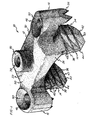
Fig. 1 is a perspective view of a spinal staple in accordance with the invention; -
Fig. 2 is a front elevation view of the spinal staple ofFig. 1 ; -
Fig. 3 is a perspective view of the spinal staple showing the underside of the staple; -
Fig. 4 is a top plan view of the spinal staple; -
Fig. 5 is an end elevation view of the spinal staple; -
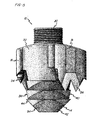
Fig. 6 is a perspective view of two of the spinal staples in accordance with the invention, aligned in end-to-end adjoining relationship; -
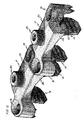
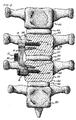
Fig. 7 is a top plan view of three of the spinal staples of the invention installed in a spine in end-to-end relationship; -
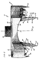
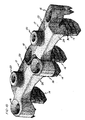
Fig. 8 is an elevation view in partial section of a spinal correction system in accordance with the invention affixed to two vertebrae so as to span two endplate growth centers and an intervening disk; -
Fig. 9 is a top plan view of an alternative embodiment of the spinal staple in accordance with the invention; and -
Fig. 10 is a perspective view of two of the alternative embodiment spinal staples aligned in end-to-end adjoining relationship. - Referring to
Figs. 1-6 , aspinal staple 10 constructed in accordance with the invention is shown. Thestaple 10 includes abridge member 12, a pair of spaced apartlegs 14, a leftfastener retaining portion 16, a rightfastener retaining portion 18, and a threadedpost 20. Although reference will be made throughout this description to terms implying direction such as left, right, front, back, upper and lower, these terms are used only for convenience in describing thestaple 10 and should not be read as limiting thestaple 10 to any particular orientation. - The
bridge member 12 includes anupper surface 22, an opposedlower surface 24, afront side 26, an opposed backside 28, aleft end 30 and an opposedright end 32. Theupper surface 22 is substantially planar in a direction extending from theleft end 30 to theright end 32, and is convex in a direction from thefront side 26 to theback side 28, as may best be seen inFig. 5 when the staple is viewed from one of the ends. Thelower surface 24 is concave in a direction from theleft end 30 to theright end 32 and from thefront side 26 to theback side 28, as may best be seen inFigs. 2 and3 , Thebridge member 12 thus defines a pair of cooperating arches, a first arch extending between the left andright ends sides - The
legs 14 extend downwardly from thelower surface 24 at the left andright ends leg 14 has anouter surface 34, an opposedinner surface 36 such that theinner surfaces 36 are facing each other, afront surface 38, and anopposed back surface 40. Each of thelegs 14 has a width as measured from the fromsurface 38 to theback surface 40, which is substantially equal to the width of thebridge member 12 as measured from thefront side 26 to theback side 28. Thelegs 14 narrow slightly from thefront surface 38 to theback surface 40 toward theirrespective tips 42 which are sharply tapered to define ablade edge 43.Barbs 44 project outwardly from each of the outer, inner, front, andback surfaces - Each
barb 44 includes a retainingsurface 45 facing generally away from therespective tip 42 and facing generally toward thebridge member 12. As such, thebarbs 44 are adapted to inhibit withdrawal movement of the staple 10 once the staple 10 has been positioned in its fixation environment, such as a vertebra. Theinner surface 36 of thelegs 14 are preferably splayed, or angled, away from each other at an angle of about 10° as measured from a vertical plane 47 extending perpendicularly through the cross-section of thebridge member 12. Theouter surfaces 34 of thelegs 14 extend downwardly substantially perpendicular to thebridge number 12 and substantially parallel to thevertical plane 45. - The left
fastener retaining portion 16 extends outwardly from the bridge member leftend 30. The rightfastener retaining portion 18 extends outwardly from the bridge memberright end 32. Each of thefastener retaining portions passageway 46 therethrough adapted to receive therein a fastener, such as a screw. Thefastener retaining portions passageways 46 are adapted to guide a fastener in a direction substantially parallel to thelegs 14. Also, thefastener retaining portions staples 10 are in end-to-ond abutting relation, as shown inFig. 6 , then thefastener retaining portions fastener retaining portion 16 on onestaple 10 lies alongside the rightfastener retaining portion 18 of theother staple 10. Moreover, the back side 51 of the leftfastener retaining portion 16 of afirst staple 10 is positioned in proximity to and facing the front side 49 of the rightfastener retaining portion 18 of an adjacentsecond staple 10, - As may be seen in
Fig. 4 , alongitudinal axis 48 extends through the center of the staple 10 from theleft end 30 top theright end 32. In a preferred embodiment, the left and rightfastener retaining portions longitudinal axis 48. - In an alternative embodiment, shown in
Figs. 9 and10 , thefastener retaining portions bridge member 12 such that bothportions longitudinal axis 48. In such an alternative embodiment, thestaples 10 may be arranged in end-to-end abutting relation by rotating adjoining staples end-for-end 180°, Then, the left (right) fastener retaining portion 16 (18) of onestaple 10 will lie alongside the left (right) faster retaining portion 16 (18) of the adjoiningstaple 10. Moreover the back side 51 of onefastener retaining portion fastener retaining portion - Each of the
fastener retaining portions portion 50 adapted to receive the head of a fastener therein. In addition, eachfastener retaining portion lower surface 52 having pointedprojections 54 extending downwardly therefrom for engaging underlying bone.Pointed barbs 56 also extend downwardly from thefastener retaining portions - The threaded
post 20 extends upwardly from theupper surface 22 of thebridge member 12. The threadedpost 20 cooperates with thebridge member 12 to define apassageway 58 coaxial with thepost 20 and extending through thepost 20 to thelower surface 24 of thebridge member 12. The threadedpost 20 permits the attachment of additional hardware or instruments to thestaple 10, while thepassageway 58 allows for the passage of a guide wire, if desired. Further, the cannulated threadedpost 20 facilitates attachment of a threaded removable, cannulated impaction devise. - The staple 1 0 may be made of titanium, surgical stainless steel, or any other material sufficiently strong to resist the growth of a spinal column, and sufficiently non-reactive in the environment of a living animal.
- Referring to
Figs. 7 and8 , thestaples 10 are inserted into thevertebrae 60 of an animal having an immature or growing spine exhibiting scoliosis or other spinal deformity. Thestaples 10 are of a size such that thelegs 14 are spaced far enough apart that thestaples 10 will bridge longitudinally or lengthwise aligned, adjoiningvertebrae 60 having confronting endplate growth centers 62 with predetermined thieknesses, and an interveningdisk 64 therebetween. Thestaples 10 are driven into an intermediate portion 66, between endplate growth centers 62, of adjoiningvertebrae 60 on the convex side of the curved spine. Thelegs 14 are of such a length that they extend into thevertabrae 60 no more than one-half the transverse diameter of each vertebra. When positioned properly, thelegs 14 are fully embedded in thevertebrae 60, and theprojections 54 andbarbs 56 of thefastener retaining portions staple 10 is in place,fasteners 68 such as screws, barbed stakes, or the like are inserted through thepassageways 46 in thefastener retaining portions vertebrae 60. - The spinal correction system, when installed on a growing spine having abnormal curvature defining a convex side and an opposed concave side, with the spine including a plurality of lengthwise adjoining
vertebrae 60 each having a pair of endplate growth centers 62, or longitudinal growth plates, with an intermediate portion 66 in between, thevertebrae 60 also having a particular diameter or thickness in a direction measured from the convex side to the concave side, is broadly seen to include a first bone engaging means orleg 14 that penetrates the convex side of an intermediate portion 66 of a first vertebra to a depth of less than oxic-half the diameter of the first vertebra, a second bone engaging means orleg 14 penetrating the convex side of an intermediate portion 66 of a second vertebra to a depth of less than onc-half the diameter of the second vertebra, and abridge member 12 rigidly connecting the first and secondbone engaging means 14. As may be appreciated, the concavelower suface 24 of each staple 10 substantially matches or follows the contour of the vertebral body defined by thevertebrae 60. - The
spinal correction system 10 thus corrects the abnormal curvature of the growing spine by inhibiting or retarding the growth of the endplate growth centers 62 captured between the first and second bone engaging means 14 on the convex side of the spine, while permitting the unrestrained growth of the endplate growth centers 62 on the concave side of the spine. As the spine continues to grow, the concave side of the spine will grow faster relative to the convex side, thereby resulting in flattening of the curvature and straightening of the spine. - While the
legs 14 are primarily responsible for restraining the growth of the endplate growth centers 62 captured therebetween, it will be seen that thefastener retaining portions fasteners 68 also contribute to restraining the growth of the endplate growth centers 62 captured therebetween. The less 14 may even be omitted provided that thefastener retaining portions fasteners 68 are adapted to sufficiently resist the spreading forces due to lengthwise growth of the end plate growth centers 62. - While the spinal correction system is intended primarily for correcting abnormal lateral curvature of an immature or growing spine, it may also be used for spinal correction in humans having mature or non-growing spines. In such cases, discectomy and fusion would be required before fixing the system to the vertebrae.
- Embodiments of the invention can be described with reference to the following numbered clauses, with preferred features laid out in the dependent clauses:
- 1. A spinal correction system comprising:
- a bridge member having an upper surface, an opposed lower surface, a front side, an opposed back side, a left and, and an opposed right end;
- a left fastener retaining portion extending from said bridge member left end, said left fastener retaining portion having front and back sides;
- a right fastener retaining portion extending from said bridge member right end, said right fastener retaining portion having front and back sides; and
- wherein each of said fastener retaining portions are proportioned so that when first and second ones of said spinal correction systems are positioned with one of said ends of said first spinal correction system adjacent one of said ends of said second spinal correction system thereby defining a pair of adjacent ends, each of said fastener retaining portions extending from said adjacent ends is positioned with one of said sides facing one of said sides of the other said fastener retaining portion extending from the other said adjoining end,
- 2. A spinal correction system according to clause 1 wherein:
- said left fastener retaining portion extends from said bridge member left end adjacent one of said bridge member front side and said bridge member back side; and
- said right fastener retaining portion extends from said bridge member right end adjacent the opposite said bridge member side as said left fastener retaining portion.
- 3. A spinal correction system according to clause 1 wherein:
- said left fastener retaining portion extends from said bridge member left end adjacent one of said bridge member front side and said bridge member back side; and
- said right fastener retaining portion extends from said bridge member right end adjacent the same said bridge member side as said left fastener retaining portion.
- 4. A spinal correction system according to clause 1 wherein:
- each said fastener retaining portion defines a passageway therethrough adapted to receive a fastener.
- 5. A spinal correction system according to clause 1 wherein;
each said fastener retaining portion has a plurality of projections extending from a lower surface thereof. - 6. A spinal correction system according to clause 1 wherein;
said bridge member lower surface is concave in a direction from said left end to said right end to substantially match the contour of a vertebral body. - 7. A spinal correction system according to clause 1 wherein:
- said bridge member lower surface is concave in a direction from said front side to said back side to closely match the contour of a vertebral body
- 8. A spinal correction system according to clause 1 wherein:
- said bridge member defines a central longitudinal axis extending along a direction from said left end to said right end;
- said left fastener retaining portion lies entirely to one side of said central longitudinal axis;
- said right fastener retaining portion lies entirely to the other side of said central longitudinal axis;
- each of said fastener retaining portions defines a passageway extending from an upper surface thereof through a lower surface thereof, said passageway adapted to receive a fastener therein; and
- each of said fastener retaining portions defines a countersunk portion coaxial with said passageway adjacent said fastener retaining portion upper surface said countersunk portion adopted to receive a fastener head therein.
- 9. A spinal correction system according to clause 1 wherein:
- a threaded post extends from said bridge member upper surface.
- 10. A spinal correction system according to clause 9 wherein:
- said threaded post defines a passageway coaxial therewith
- 11. A spinal correction system according to clause 11 further comprising:
- a pair of spaced apart legs extending from said bridge member lower surface proximate said left and right ends.
- 12. A spinal correction system according to clause 11 wherein:
- said legs include barbs having at least one retaining surface adapted to inhibit withdrawal movement of said spinal correction system once said spinal correction system has been positioned in a fixation environment.
- 13. A spinal correction systems according to clause 11 wherein:
- each said leg has a width substantially equal to a width of said bridge member as measured from said front side to said back side.
- 14. A spinal correction system according to clause 11 wherein:
- each said leg includes an inner surface which is splayed outwardly away from said inner surface of the other said leg as measured from a plane passing between said legs substantially perpendicular to said bridge member.
- 15. A spinal correction system according to clause 11 wherein:
- said left fastener retaining portion extends from said bridge member left end adjacent said bridge member front side;
- said right fastener retaining portion extends from said bridge member right end adjacent said bridge member back side; and
- each of said fastener retaining portions are adapted to guide a fastener in a direction substantially parallel to said legs.
- 16. A spinal correction system for a spine including longitudinally aligned vertebrae, said vertebrae having confronting endplate growth centers with predetermined thicknessss, a longitudinally extending span defined between said confronting endplate growth center thicknesses, and an intervening disk positioned intermediate said end plate growth centers, said vertebrae having predetermined transverse diameters, said system comprising:
- a bridge member having an upper surface, an opposed lower surface, a front side, an opposed back side, a left end, and an opposed right end, the length of said bridge member from said
left end 10 said right end being substantially equal to said longitudinally extending span; - a left fastener retaining portion extending from said bridge member left end, said left fastener retaining portion having front and back sides; and
- a right fastener retaining portion extending from said bridge member right end, said right fastener retaining portion having front and back sides.
- a bridge member having an upper surface, an opposed lower surface, a front side, an opposed back side, a left end, and an opposed right end, the length of said bridge member from said
- 17. A spinal correction system according to
clause 16 wherein:- each of said fastener retaining portions are proportioned so that when first and second ones of said spinal correction systems are positioned with one of said ends of said first spinal correction system adjacent one of said ends of said second spinal correction system thereby defining a pair of adjacent ends, each of said fastener retaining portions extending from said adjoining ends is positioned with one of said sides facing one of said sides of the other said fastener retaining portion extending from the other said adjoining end.
- 18. A spinal correction system according to
clause 16 wherein:- said left fastener retaining portion extends from said bridge member left end adjacent one of said bridge member front side and said bridge member back side; and
- said right fastener retaining portion extends from said bridge member right end adjacent the opposite said bridge member side as said left fastener retaining portion.
- 19. A spinal correction system according to
clause 16 wherein:- said left fastener retaining portion extends from said bridge member left end adjacent one of said bridge member front side or said bridge member back side; and
- said right fastener retaining portion extends from said bridge member right end adjacent the same said bridge member side as said left fastener retaining portion.
- 20. A spinal correction system according to
clause 16 further comprising:- a pair of spaced apart legs extending from said bridge member lower surface proximate said left and right ends.
- 21. A spinal correction system according to clause 19 wherein:
- said legs are proportioned to extend less than one-half said diameter of said vertebrae.
- 22. A spinal correction system on a growing spine having abnormal curvature defining a convex side, the spine including a plurality of lengthwise adjoining vertebrae, the vertebrae including endplate growth centers with an intermediate portion therebetween, the vertebrae further having transverse diameters, the system comprising:
- a first bone engaging means penetrating the convex side of an intermediate portion of a first vertebra to a depth of about one half the diameter of the first vertebra:
- a second bone engaging means penetrating the convex side of an intermediate portion of a second vertebra to a depth of less than one-half the diameter of the second vertebra; and
- a bridge member rigidly connecting said first means and said second means;
- whereby said system corrects the abnormal curvature of the growing spine by inhibiting the growth of the endplate growth centers between said first and second bone engaging means on the convex side of the spine.
- 23. A spinal correction system according to
clause 22 wherein:- said first and second bone engaging means each comprise a substantially wedge-shaped leg extending substantially perpendicularly proximate from respect first and second ends of said bridge member.
- 24. A spinal correction system according to
clause 22 wherein:- said first and second bone engaging means each comprise a fastener retaining portion extending substantially lengthwise from respective first and second ends of said bridge member.
- 25. A spinal correction system according to
clause 24 wherein:- said first and second fastener retaining portions are proportioned so that when two said systems are arranged end-to-end on a spine, adjoining fastener retaining portions lie adjacent each other.
- 26. A spinal correction system comprising:
- a bridge member having an upper surface, as opposed lower surface, a front side, an opposed back side, a left end, and an opposed right end, said upper surface substantially planar in a direction from said left end to said right end, said upper surface convex in a direction from said front side to said back side, said lower surface concave in a direction from said left end to said right end;
- a pair of spaced apart legs extending from said lower surface at said left and right ends, each of said legs being substantially wedge-sttaped, each of said legs having a width substantially equal to a width of said bridge member from said front side to said back side, each said leg having an outer surface and as opposed inner surface, said inner surfaces facing each other, each said leg having a front surface and an opposed back surface, each said leg having a plurality of barbs projecting from each of said outer, inner, front, and back surfaces, said inner surfaces of said legs angled away from each other from vertical:
- a left fastener retaining portion extending from said bridge member left end;
- a right fastener retaining portion extending from said bridge member right end;
- each of said fastener retaining portions defining a passageway therethrough adapted to receive a fastener therein, each of said fastener retaining portions adapted to guide a fastener in a direction substantially parallel to said legs, each of said fastener retaining portions having a plurality of projections extending from their lower surfaces; and
- a threaded post extending from said upper surface of said bridge member, said bridge member and said threaded post cooperating to define a passageway therethrough, said passageway coaxial with said threaded post, said threaded post facilitating the attachment of a cannulated immovable impactor device,
Claims (9)
- A spinal correction system for a spine including longitudinally aligned vertebrae, said vertebrae having confronting endplate growth centers with predetermined thicknesses, a longitudinally extending span defined between said confronting endplate growth center thicknesses, and an intervening disk positioned intermediate said end plate growth centers, said vertebrae having predetermined transverse diameters, said system comprising a bridge member having an upper surface, an opposed lower surface, a front side, an opposed back side, a left end, and an opposed right end, the length of said bridge member from said left end to said right end being substantially equal to said longitudinally extending span, a left fastener retaining portion extending from said bridge member left end, said left fastener retaining portion having front and back sides, and a right fastener retaining portion extending from said bridge member right end, said right tastener retaining portion having front and back sides.
- A spinal correction system according to claim 1 wherein each of said fastener retaining portions are proportioned so that when first and second ones of said spinal correction systems are positioned with one of said ends of said first spinal correction system adjacent one of said ends of said second spinal correction system thereby defining a pair of adjacent ends, each of said fastener retaining portions extending from said adjoining end is positioned with one of said sides facing one of said sides of the other said fastener retaining portion extending from the other said adjoining end.
- A spinal correction system according to either claim 1 or claim 2 wherein said left fastener retaining portion extends from said bridge member left end adjacent one of said bridge member front side and said bridge member back side, and said right fastener retaining portion extends from said bridge member right end adjacent the opposite said bridge member side as said left fastener retaining portion.
- A spinal correction system according to either claim 1 or claim 2 wherein said left fastener retaining portion extends from said bridge member lett end adjacent one of said bridge member front aide or said bridge member back side, and said right fastener retaining portion extends from said bridge member right end adjacent the same said bridge member side as said left fastener retaining portion.
- A spinal correction system according to any preceding claim further comprising a pair of spaced apart legs extending from said bridge member lower surface proximate said left and right ends.
- A spinal correction system according to claim 5 wherein said legs are proportioned to extend less than one-half said diameter of said vertebrae.
- A spinal correction system according to claim 6 wherein said legs are substantially wedge-shaped and extend substantially perpendicularly proximate from respective first and second ende of said bridge member.
- A spinal correction systems according to any preceding claim wherein said fastener retaining portions extending substantially lengthwise from respective first and second ende of said bridge member.
- A spinal correction system according to claim 1 wherein said bridge member has an upper surface, an opposed lower surface, a front side, an opposed back side, a left end, and an opposed right end, said upper surface substantially planar in a direction from said left end to said right end, said upper surface convex in a direction from said front side to said back side, said lower surface concave in a direction from said left end to said right end, wherein the system further comprises a pair of spaced spart legs extending from said lower surface
at said left and right ends, each of said legs being substantially wedge-shaped, each of said legs having a width substantially equal to a width of said bridge member from said front side to said back side, each said leg having an outer surface and an opposed inner surface, said inner surfaces facing each other, each said leg having a front surface and an opposed back surface, each said leg having a plurality of barbe projecting from each of said outer, inner, front, and back surfaces, said inner surfaces of said legs angled away from each other from vertical, wherein each of said fastener retaining portions defines a passageway therethrough adapted to receive a fastener therein, each of said fastener retaining portions adapted to guide a fastener in a direction substantially parallel to said legs, each of said fastener retaining portions having a plurality of projections extending from their lower surfaces, and wherein a threaded post extends from said upper surface of said bridge member, said bridge member and said threaded post cooperating to define a passageway therethrough, said passageway coaxial with said threaded post, said threaded post facilitating the attachment of a cannulated removable impactor device.
Applications Claiming Priority (5)
| Application Number | Priority Date | Filing Date | Title |
|---|---|---|---|
| US14270799P | 1999-07-07 | 1999-07-07 | |
| PCT/US2000/018491 WO2001003570A2 (en) | 1999-07-07 | 2000-07-06 | Spinal correction system |
| EP00947065.9A EP1370183B1 (en) | 1999-07-07 | 2000-07-06 | Spinal correction system |
| US10/030,440 US6746450B1 (en) | 1999-07-07 | 2000-07-06 | Spinal correction system |
| US10/862,660 US7481830B2 (en) | 1999-07-07 | 2004-06-07 | Spinal correction system |
Related Parent Applications (3)
| Application Number | Title | Priority Date | Filing Date |
|---|---|---|---|
| EP00947065.9A Division-Into EP1370183B1 (en) | 1999-07-07 | 2000-07-06 | Spinal correction system |
| EP00947065.9A Division EP1370183B1 (en) | 1999-07-07 | 2000-07-06 | Spinal correction system |
| EP00947065.9 Division | 2000-07-06 |
Publications (3)
| Publication Number | Publication Date |
|---|---|
| EP2292167A2 true EP2292167A2 (en) | 2011-03-09 |
| EP2292167A3 EP2292167A3 (en) | 2013-08-21 |
| EP2292167B1 EP2292167B1 (en) | 2015-11-25 |
Family
ID=36603569
Family Applications (2)
| Application Number | Title | Priority Date | Filing Date |
|---|---|---|---|
| EP10179901.3A Expired - Lifetime EP2292167B1 (en) | 1999-07-07 | 2000-07-06 | Spinal correction system |
| EP00947065.9A Expired - Lifetime EP1370183B1 (en) | 1999-07-07 | 2000-07-06 | Spinal correction system |
Family Applications After (1)
| Application Number | Title | Priority Date | Filing Date |
|---|---|---|---|
| EP00947065.9A Expired - Lifetime EP1370183B1 (en) | 1999-07-07 | 2000-07-06 | Spinal correction system |
Country Status (5)
| Country | Link |
|---|---|
| US (3) | US6746450B1 (en) |
| EP (2) | EP2292167B1 (en) |
| JP (2) | JP3771492B2 (en) |
| AU (1) | AU768636B2 (en) |
| WO (1) | WO2001003570A2 (en) |
Families Citing this family (129)
| Publication number | Priority date | Publication date | Assignee | Title |
|---|---|---|---|---|
| EP2292167B1 (en) * | 1999-07-07 | 2015-11-25 | Children's Hospital Medical Center | Spinal correction system |
| US7727246B2 (en) * | 2000-12-06 | 2010-06-01 | Ethicon Endo-Surgery, Inc. | Methods for endoluminal treatment |
| US7232445B2 (en) | 2000-12-06 | 2007-06-19 | Id, Llc | Apparatus for the endoluminal treatment of gastroesophageal reflux disease (GERD) |
| US8062314B2 (en) | 2000-12-06 | 2011-11-22 | Ethicon Endo-Surgery, Inc. | Methods for the endoluminal treatment of gastroesophageal reflux disease (GERD) |
| US20020138086A1 (en) * | 2000-12-06 | 2002-09-26 | Robert Sixto | Surgical clips particularly useful in the endoluminal treatment of gastroesophageal reflux disease (GERD) |
| US6969610B2 (en) * | 2001-01-12 | 2005-11-29 | University Of Rochester | Methods of modifying cell structure and remodeling tissue |
| US6974462B2 (en) * | 2001-12-19 | 2005-12-13 | Boston Scientific Scimed, Inc. | Surgical anchor implantation device |
| JP3708883B2 (en) * | 2002-02-08 | 2005-10-19 | 昭和医科工業株式会社 | Vertebral space retainer |
| FR2836370B1 (en) * | 2002-02-27 | 2005-02-04 | Materiel Orthopedique En Abreg | ANCHOR PLATE FOR OSTEOSYNTHESIS DEVICE OF THE VERTEBRAL COLUMN, AND DEVICE COMPRISING SAME |
| US8105366B2 (en) * | 2002-05-30 | 2012-01-31 | Warsaw Orthopedic, Inc. | Laminoplasty plate with flanges |
| JP2004097707A (en) * | 2002-09-12 | 2004-04-02 | Showa Ika Kohgyo Co Ltd | Vertebral body plate for spine fixing system |
| US7811312B2 (en) | 2002-12-04 | 2010-10-12 | Morphographics, Lc | Bone alignment implant and method of use |
| US8100976B2 (en) * | 2003-04-21 | 2012-01-24 | Rsb Spine Llc | Implant subsidence control |
| US8613772B2 (en) * | 2003-04-21 | 2013-12-24 | Rsb Spine Llc | Lateral mount implant device |
| US20050096652A1 (en) * | 2003-10-31 | 2005-05-05 | Burton Charles V. | Integral flexible spine stabilization device and method |
| JP4768713B2 (en) * | 2004-03-23 | 2011-09-07 | ウォーソー・オーソペディック・インコーポレーテッド | System for correcting spinal deformities |
| US8034085B2 (en) | 2004-05-28 | 2011-10-11 | Depuy Spine, Inc. | Non-fusion spinal correction systems and methods |
| US7901435B2 (en) | 2004-05-28 | 2011-03-08 | Depuy Spine, Inc. | Anchoring systems and methods for correcting spinal deformities |
| US7883510B2 (en) * | 2004-08-27 | 2011-02-08 | Depuy Spine, Inc. | Vertebral staples and insertion tools |
| FR2874809B1 (en) * | 2004-09-06 | 2008-02-01 | Newdeal Sa Sa | IMPLANT FOR FIXING A BONE GRAFT WITHIN A JOINT TO ENSURE THE ARTHRODESIS OF THE JOINT |
| JP2008518658A (en) * | 2004-10-28 | 2008-06-05 | アクシアル・バイオテック・インコーポレーテッド | Apparatus and method for inflating concave scoliosis |
| US7648508B2 (en) * | 2004-11-30 | 2010-01-19 | Stryker Trauma S.A. | Bone plating implants, instruments and methods |
| US20060235409A1 (en) * | 2005-03-17 | 2006-10-19 | Jason Blain | Flanged interbody fusion device |
| US8123749B2 (en) | 2005-03-24 | 2012-02-28 | Depuy Spine, Inc. | Low profile spinal tethering systems |
| US7942903B2 (en) | 2005-04-12 | 2011-05-17 | Moskowitz Ahmnon D | Bi-directional fixating transvertebral body screws and posterior cervical and lumbar interarticulating joint calibrated stapling devices for spinal fusion |
| US11903849B2 (en) | 2005-04-12 | 2024-02-20 | Moskowitz Family Llc | Intervertebral implant and tool assembly |
| WO2006122194A1 (en) | 2005-05-11 | 2006-11-16 | Children's Hospital Medical Center | Spinal correction system |
| WO2007008209A1 (en) * | 2005-07-13 | 2007-01-18 | Boston Scientific Scimed Inc. | Snap fit sling anchor system and related methods |
| US8062294B2 (en) * | 2005-09-15 | 2011-11-22 | Spineform Llc | Implant with integral fastener retention |
| US9072554B2 (en) * | 2005-09-21 | 2015-07-07 | Children's Hospital Medical Center | Orthopedic implant |
| WO2007035892A1 (en) * | 2005-09-21 | 2007-03-29 | Children's Hospital Medical Center | Endoscopic instruments and method for the delivery of spinal implant |
| US20070078466A1 (en) * | 2005-09-30 | 2007-04-05 | Restoration Robotics, Inc. | Methods for harvesting follicular units using an automated system |
| US8357181B2 (en) | 2005-10-27 | 2013-01-22 | Warsaw Orthopedic, Inc. | Intervertebral prosthetic device for spinal stabilization and method of implanting same |
| US20110160766A1 (en) * | 2005-11-02 | 2011-06-30 | Hendren Ronald D | Medical Affixation Device |
| US20070173822A1 (en) * | 2006-01-13 | 2007-07-26 | Sdgi Holdings, Inc. | Use of a posterior dynamic stabilization system with an intradiscal device |
| US20070233108A1 (en) * | 2006-03-15 | 2007-10-04 | Stalcup Gregory C | Spine fixation device |
| US8414616B2 (en) * | 2006-09-12 | 2013-04-09 | Pioneer Surgical Technology, Inc. | Mounting devices for fixation devices and insertion instruments used therewith |
| US9017388B2 (en) * | 2006-09-14 | 2015-04-28 | Warsaw Orthopedic, Inc. | Methods for correcting spinal deformities |
| US20080091186A1 (en) * | 2006-10-13 | 2008-04-17 | Tyco Electronics Corporation | Electro-surgical device RF energy needle electrical shorting plate |
| EP2120749B1 (en) * | 2006-12-07 | 2020-05-20 | AlpineSpine LLC | Press-on pedicle screw assembly |
| US7931676B2 (en) * | 2007-01-18 | 2011-04-26 | Warsaw Orthopedic, Inc. | Vertebral stabilizer |
| US8308801B2 (en) * | 2007-02-12 | 2012-11-13 | Brigham Young University | Spinal implant |
| US9314346B2 (en) * | 2007-02-12 | 2016-04-19 | Brigham Young University | Spinal implant |
| US8470002B2 (en) * | 2007-02-20 | 2013-06-25 | Warsaw Orthopedic, Inc. | Resorbable release mechanism for a surgical tether and methods of use |
| US8920479B2 (en) * | 2007-03-30 | 2014-12-30 | K2M, Inc. | Anterior vertebral plate with spike fixation |
| GB0707285D0 (en) * | 2007-04-17 | 2007-05-23 | Burke John | Implantable apparatus for modulation of skeletal growth |
| US8292958B1 (en) | 2007-07-02 | 2012-10-23 | Theken Spine, Llc | Spinal cage having deployable member |
| US10342674B2 (en) | 2007-07-02 | 2019-07-09 | Theken Spine, Llc | Spinal cage having deployable member |
| US8864829B1 (en) | 2007-07-02 | 2014-10-21 | Theken Spine, Llc | Spinal cage having deployable member |
| US8142508B1 (en) | 2007-07-02 | 2012-03-27 | Theken Spine, Llc | Spinal cage having deployable member which is removable |
| US8545562B1 (en) | 2007-07-02 | 2013-10-01 | Theken Spine, Llc | Deployable member for use with an intervertebral cage |
| US20090024171A1 (en) * | 2007-07-19 | 2009-01-22 | Vincent Leone | Anatomical Anterior Vertebral Plating System |
| US20090149884A1 (en) * | 2007-08-02 | 2009-06-11 | Redyns Medical, Llc | System and method for bridge anchor tendon attachment |
| US8986305B2 (en) * | 2007-09-11 | 2015-03-24 | Kamran Aflatoon | Method of lateral facet approach, decompression and fusion using screws and staples as well as arthroplasty |
| US8267997B2 (en) | 2007-11-12 | 2012-09-18 | Theken Spine, Llc | Vertebral interbody compression implant |
| US20090222047A1 (en) * | 2008-03-03 | 2009-09-03 | Michael Graham | Implant for correcting skeletal mechanics |
| US7909857B2 (en) * | 2008-03-26 | 2011-03-22 | Warsaw Orthopedic, Inc. | Devices and methods for correcting spinal deformities |
| US8685026B2 (en) * | 2008-05-23 | 2014-04-01 | Warsaw Orthopedic, Inc. | Devices and methods for releasing tension on a surgical tether |
| EP2135562B1 (en) * | 2008-06-20 | 2015-09-09 | Arthrex, Inc. | Wedged profile plate |
| US20100106202A1 (en) * | 2008-08-12 | 2010-04-29 | Jamy Gannoe | System and method for distal radioulnar joint resurfacing with dynamic fixation |
| US8821555B2 (en) * | 2009-02-11 | 2014-09-02 | Howmedica Osteonics Corp. | Intervertebral implant with integrated fixation |
| CA2743721A1 (en) * | 2009-02-19 | 2010-08-26 | Anton E. Bowden | Compliant dynamic spinal implant |
| WO2010096773A1 (en) | 2009-02-20 | 2010-08-26 | Spartan Cage Holding, Llc | Interbody fusion system with intervertebral implant retention assembly |
| WO2010096829A2 (en) | 2009-02-23 | 2010-08-26 | Crocker Spinal, L.L.C. | Press-on link for surgical screws |
| US9220547B2 (en) | 2009-03-27 | 2015-12-29 | Spinal Elements, Inc. | Flanged interbody fusion device |
| JP5591912B2 (en) * | 2009-04-15 | 2014-09-17 | ジンテス ゲゼルシャフト ミット ベシュレンクテル ハフツング | Arcuate fixing member |
| US8641766B2 (en) | 2009-04-15 | 2014-02-04 | DePuy Synthes Products, LLC | Arcuate fixation member |
| US9408715B2 (en) | 2009-04-15 | 2016-08-09 | DePuy Synthes Products, Inc. | Arcuate fixation member |
| US9566098B2 (en) | 2009-04-23 | 2017-02-14 | University Of Massachusetts | Bone fixture assembly |
| WO2010124230A1 (en) | 2009-04-23 | 2010-10-28 | University Of Massachusetts | Bone fixture assembly |
| MX2012000994A (en) | 2009-07-24 | 2012-06-25 | Spinal USA LLC | Bone plate screw-blocking systems and methods. |
| WO2011019699A2 (en) | 2009-08-10 | 2011-02-17 | Howmedica Osteonics Corp | Intervertebral implant with integrated fixation |
| US20110087229A1 (en) * | 2009-10-12 | 2011-04-14 | University Of Utah | Bone fixation and compression systems |
| US9157497B1 (en) | 2009-10-30 | 2015-10-13 | Brigham Young University | Lamina emergent torsional joint and related methods |
| US8211151B2 (en) * | 2009-10-30 | 2012-07-03 | Warsaw Orthopedic | Devices and methods for dynamic spinal stabilization and correction of spinal deformities |
| US9033993B2 (en) | 2009-11-03 | 2015-05-19 | Howmedica Osteonics Corp. | Intervertebral implant with integrated fixation |
| US9480511B2 (en) | 2009-12-17 | 2016-11-01 | Engage Medical Holdings, Llc | Blade fixation for ankle fusion and arthroplasty |
| US8998903B2 (en) | 2010-03-10 | 2015-04-07 | Orthohelix Surgical Designs, Inc. | Wedge opening osteotomy plate |
| US8647369B2 (en) | 2010-05-19 | 2014-02-11 | Josef E. Gorek | Minimal profile anterior bracket for spinal fixation |
| EP3178448B1 (en) | 2010-12-16 | 2018-08-01 | Engage Medical Holdings, LLC | Arthroplasty systems |
| US8992579B1 (en) | 2011-03-08 | 2015-03-31 | Nuvasive, Inc. | Lateral fixation constructs and related methods |
| US8870929B2 (en) | 2011-04-13 | 2014-10-28 | Polyvalor, Limited Partnership Valorisation HSJ, Limited Partnership | Surgical devices for the correction of spinal deformities |
| EP2517660B1 (en) | 2011-04-25 | 2018-03-07 | Nexus Spine, L.L.C. | Coupling system to connect two or more surgical screws |
| EP2717807A2 (en) | 2011-06-07 | 2014-04-16 | Brigham Young University | Serpentine spinal stability device and associated methods |
| BR112014000796A2 (en) * | 2011-07-11 | 2017-03-01 | Vidacare Corp | sternal locators and associated systems and methods |
| US10098677B2 (en) | 2011-09-06 | 2018-10-16 | Globus Medical, Inc. | Spinal plate |
| US9427330B2 (en) | 2011-09-06 | 2016-08-30 | Globus Medical, Inc. | Spinal plate |
| US9254130B2 (en) | 2011-11-01 | 2016-02-09 | Hyun Bae | Blade anchor systems for bone fusion |
| US9615856B2 (en) | 2011-11-01 | 2017-04-11 | Imds Llc | Sacroiliac fusion cage |
| US10064618B2 (en) * | 2012-01-20 | 2018-09-04 | Zimmer, Inc. | Compression bone staple |
| US9060815B1 (en) | 2012-03-08 | 2015-06-23 | Nuvasive, Inc. | Systems and methods for performing spine surgery |
| US10238382B2 (en) | 2012-03-26 | 2019-03-26 | Engage Medical Holdings, Llc | Blade anchor for foot and ankle |
| US8998904B2 (en) * | 2012-07-17 | 2015-04-07 | Fastforward Surgical Inc. | Winged tether plate and method of use for reducing angular bone deformity |
| US9072547B2 (en) * | 2012-11-06 | 2015-07-07 | Globus Medical, Inc. | Polyaxial cross connector |
| WO2015094410A1 (en) * | 2013-12-20 | 2015-06-25 | Paragon 28, Inc. | Orthopedic bone plate and locking tab apparatus and method of use |
| US9993273B2 (en) | 2013-01-16 | 2018-06-12 | Mako Surgical Corp. | Bone plate and tracking device using a bone plate for attaching to a patient's anatomy |
| EP4309613A3 (en) | 2013-01-16 | 2024-03-06 | Stryker Corporation | Navigation systems for indicating line-of-sight errors |
| CN105828732B (en) | 2013-07-16 | 2019-03-22 | 飞进外科公司 | For reducing the bone plate and its application method of angulare deformation |
| US9517089B1 (en) | 2013-10-08 | 2016-12-13 | Nuvasive, Inc. | Bone anchor with offset rod connector |
| EP3089691B1 (en) * | 2013-12-31 | 2021-02-17 | Mako Surgical Corp. | Systems for implantation of a spinal plate |
| WO2015191884A1 (en) | 2014-06-12 | 2015-12-17 | Brigham Young University | Inverted serpentine spinal stability device and associated methods |
| US10729419B2 (en) | 2014-10-23 | 2020-08-04 | Medos International Sarl | Biceps tenodesis implants and delivery tools |
| US10076374B2 (en) | 2014-10-23 | 2018-09-18 | Medos International Sárl | Biceps tenodesis delivery tools |
| US10034742B2 (en) | 2014-10-23 | 2018-07-31 | Medos International Sarl | Biceps tenodesis implants and delivery tools |
| US10856966B2 (en) | 2014-10-23 | 2020-12-08 | Medos International Sarl | Biceps tenodesis implants and delivery tools |
| US10751161B2 (en) | 2014-10-23 | 2020-08-25 | Medos International Sárl | Biceps tenodesis anchor implants |
| AU2016200179B2 (en) | 2015-01-14 | 2020-09-17 | Stryker European Operations Holdings Llc | Spinal implant with porous and solid surfaces |
| AU2016200195B2 (en) | 2015-01-14 | 2020-07-02 | Stryker European Operations Holdings Llc | Spinal implant with fluid delivery capabilities |
| JP2018502693A (en) | 2015-01-27 | 2018-02-01 | スパイナル・エレメンツ・インコーポレーテッド | Facet joint implant |
| US20200383684A1 (en) * | 2015-02-24 | 2020-12-10 | Orthovestments, Llc | Orthopedic bone staple with polyaxial compression capability |
| USD851250S1 (en) | 2015-11-19 | 2019-06-11 | Orthovestments, Llc | Bone staple |
| US9649108B2 (en) * | 2015-02-24 | 2017-05-16 | Orthovestments, Llc | Orthopedic bone staple with polyaxial compression capability |
| US9615931B2 (en) * | 2015-03-20 | 2017-04-11 | Globus Medical, Inc. | Surgical plate systems |
| US9693856B2 (en) | 2015-04-22 | 2017-07-04 | DePuy Synthes Products, LLC | Biceps repair device |
| CA2930123A1 (en) | 2015-05-18 | 2016-11-18 | Stryker European Holdings I, Llc | Partially resorbable implants and methods |
| US10231824B2 (en) | 2016-04-08 | 2019-03-19 | Medos International Sárl | Tenodesis anchoring systems and tools |
| US10231823B2 (en) | 2016-04-08 | 2019-03-19 | Medos International Sarl | Tenodesis implants and tools |
| US10172645B2 (en) | 2016-05-20 | 2019-01-08 | Fastforward Surgical Inc. | Method of correcting hallux varus joint deformity |
| US10537395B2 (en) | 2016-05-26 | 2020-01-21 | MAKO Surgical Group | Navigation tracker with kinematic connector assembly |
| US10390955B2 (en) | 2016-09-22 | 2019-08-27 | Engage Medical Holdings, Llc | Bone implants |
| US11540928B2 (en) | 2017-03-03 | 2023-01-03 | Engage Uni Llc | Unicompartmental knee arthroplasty |
| US10456272B2 (en) | 2017-03-03 | 2019-10-29 | Engage Uni Llc | Unicompartmental knee arthroplasty |
| EP3459502A1 (en) | 2017-09-20 | 2019-03-27 | Stryker European Holdings I, LLC | Spinal implants |
| US11246588B2 (en) * | 2018-06-28 | 2022-02-15 | Ortho Solutions Holdings Limited | Superelastic bone compression staple in staple system |
| AU2019342137A1 (en) | 2018-09-20 | 2021-03-25 | Spinal Elements, Inc. | Spinal implant device |
| WO2021016418A1 (en) | 2019-07-23 | 2021-01-28 | Coleman Robert Glen | Tibial plateau leveling osteotomy systems and methods |
| US11642124B2 (en) | 2020-06-16 | 2023-05-09 | Ortho Solutions Holdings Limited | Reinforced bridge superelastic bone compression staple and inserter system |
| WO2022109524A1 (en) | 2020-11-19 | 2022-05-27 | Spinal Elements, Inc. | Curved expandable interbody devices and deployment tools |
| US20220226023A1 (en) * | 2021-01-18 | 2022-07-21 | Zimmer Biomet Spine, Inc. | Spinal tethering devices, systems, and methods |
Citations (12)
| Publication number | Priority date | Publication date | Assignee | Title |
|---|---|---|---|---|
| US4651724A (en) * | 1984-05-18 | 1987-03-24 | Technomed Gmk | Bone joining plate |
| DE4038082A1 (en) * | 1989-11-29 | 1991-06-06 | Asahi Optical Co Ltd | SWIRL CONNECTION ARRANGEMENT |
| EP0552109A1 (en) * | 1992-01-17 | 1993-07-21 | Cendis Medical Sarl | Bone staple |
| GB2273966A (en) * | 1993-01-05 | 1994-07-06 | Kevin Hardinge | Staple for use e.g.in osteotomy |
| US5395372A (en) * | 1993-09-07 | 1995-03-07 | Danek Medical, Inc. | Spinal strut graft holding staple |
| FR2709410A1 (en) * | 1993-09-02 | 1995-03-10 | Jbs Sa | Clamp plate for osteosynthesis |
| US5405391A (en) * | 1993-02-16 | 1995-04-11 | Hednerson; Fraser C. | Fusion stabilization chamber |
| USD364462S (en) * | 1994-03-28 | 1995-11-21 | Michelson Gary K | Spinal fixation staple |
| DE4433360A1 (en) * | 1994-07-19 | 1996-02-01 | Schaefer Micomed Gmbh | Surgical fixator rod holder |
| EP0705572A2 (en) * | 1994-10-03 | 1996-04-10 | Synthes AG, Chur | Locking plate and bone screw |
| US5603713A (en) * | 1991-09-24 | 1997-02-18 | Aust; Gilbert M. | Anterior lumbar/cervical bicortical compression plate |
| FR2754702A1 (en) * | 1996-10-18 | 1998-04-24 | Medinov Amp | DEVICE FOR SOLIDARIZING AT LEAST TWO VERTEBRAL BODIES |
Family Cites Families (113)
| Publication number | Priority date | Publication date | Assignee | Title |
|---|---|---|---|---|
| DE64462C (en) * | A. RINCKLAKE in Berlin S.W., Kommandantenstr. 82 | Lamps kerosene containers | ||
| DE20081C (en) * | O. TOEPFER in Potsdam, Mittelstrafse 39 | Rotatable window thermometer frame with hygrometer, weather vane and compaf | ||
| DE40284C (en) * | E. W. SERRELL JUN. in Chabeuil, Dröme, Frankreich | Device for tension equalization on the silk reel protected by patent 19885 | ||
| US82181A (en) * | 1868-09-15 | Improvement in paper-fasteners | ||
| DE78409C (en) * | Dr. E. Erdmann u. Dr. o. Borgmann, Halle a. S | Process for dyeing wool and silk with orthoxyazo dyes | ||
| US431175A (en) * | 1890-07-01 | Belt-fastener | ||
| US758881A (en) * | 1903-07-01 | 1904-05-03 | Charls A Yost | Clamping-dog. |
| US1425199A (en) * | 1921-05-03 | 1922-08-08 | Hartley James | Railway spike |
| US1638477A (en) * | 1926-04-07 | 1927-08-09 | Dyer Grover Lee | Gangboard cleat |
| US2134765A (en) * | 1936-06-08 | 1938-11-01 | Clamp Nail Company | Clamp nail or fastener |
| US2398603A (en) * | 1945-04-18 | 1946-04-16 | Gustave J Soderberg | Fastener |
| US2919621A (en) * | 1957-01-09 | 1960-01-05 | Jesse D Langdon | Nail-staple combination |
| US3693616A (en) * | 1970-06-26 | 1972-09-26 | Robert Roaf | Device for correcting scoliotic curves |
| US3862631A (en) | 1973-05-16 | 1975-01-28 | Down Bros | Surgical implants |
| GB1551706A (en) | 1975-04-28 | 1979-08-30 | Downs Surgical Ltd | Surgical implant |
| GB1551704A (en) | 1975-04-28 | 1979-08-30 | Downs Surgical Ltd | Surgical implant |
| GB1551705A (en) | 1975-04-28 | 1979-08-30 | Downs Surgicial Ltd | Surgial implant |
| FI53062C (en) * | 1975-05-30 | 1978-02-10 | Erkki Einari Nissinen | |
| JPS5651995A (en) | 1979-10-05 | 1981-05-09 | Green Cross Corp:The | Preparation of interferon |
| US4403606A (en) * | 1980-05-09 | 1983-09-13 | The Regents Of The University Of California | Compatible internal bone fixation plate |
| GB2083754B (en) * | 1980-09-15 | 1984-04-26 | Rezaian Seyed Mahmoud | Spinal fixator |
| SU982676A1 (en) | 1981-04-07 | 1982-12-23 | Всесоюзный научно-исследовательский и испытательный институт медицинской техники | Surgical cramp |
| DE3114136C2 (en) * | 1981-04-08 | 1986-02-06 | Aesculap-Werke Ag Vormals Jetter & Scheerer, 7200 Tuttlingen | Osteosynthesis plate |
| US4454875A (en) | 1982-04-15 | 1984-06-19 | Techmedica, Inc. | Osteal medical staple |
| US4462395A (en) | 1983-03-02 | 1984-07-31 | Johnson Lanny L | Arthroscopic ligamentous and capsular fixation system |
| US4570623A (en) * | 1983-06-02 | 1986-02-18 | Pfizer Hospital Products Group Inc. | Arched bridge staple |
| US4570618A (en) * | 1983-11-23 | 1986-02-18 | Henry Ford Hospital | Intervertebral body wire stabilization |
| GB8333442D0 (en) * | 1983-12-15 | 1984-01-25 | Showell A W Sugicraft Ltd | Devices for spinal fixation |
| US4573454A (en) * | 1984-05-17 | 1986-03-04 | Hoffman Gregory A | Spinal fixation apparatus |
| US4592346A (en) * | 1985-04-08 | 1986-06-03 | Jurgutis John A | Orthopedic staple |
| US4599086A (en) * | 1985-06-07 | 1986-07-08 | Doty James R | Spine stabilization device and method |
| US4743260A (en) * | 1985-06-10 | 1988-05-10 | Burton Charles V | Method for a flexible stabilization system for a vertebral column |
| CH668693A5 (en) | 1986-01-28 | 1989-01-31 | Sulzer Ag | MEDICAL AGRAFFE. |
| US4848328A (en) | 1986-05-20 | 1989-07-18 | Laboureau Jacques P | Agraffe for osteosynthesis |
| ZA875425B (en) * | 1986-07-23 | 1988-04-27 | Gore & Ass | Mechanical ligament |
| JPS6365060A (en) | 1986-09-05 | 1988-03-23 | Kobe Steel Ltd | Method for preheating aluminum and aluminum alloy slab in direct firing type slab heating furnace |
| US4841960A (en) | 1987-02-10 | 1989-06-27 | Garner Eric T | Method and apparatus for interosseous bone fixation |
| GB8716925D0 (en) * | 1987-07-17 | 1987-08-26 | Mehdian S M H | Apparatus for treatment of spinal disorders |
| GB8718708D0 (en) * | 1987-08-07 | 1987-09-16 | Mehdian S M H | Apparatus for treatment of spinal disorders |
| FR2623085B1 (en) * | 1987-11-16 | 1992-08-14 | Breard Francis | SURGICAL IMPLANT TO LIMIT THE RELATIVE MOVEMENT OF VERTEBRES |
| IT215084Z2 (en) | 1988-08-03 | 1990-07-30 | Torino A | VARIABLE EXCURSION CAMBRA |
| US4960420A (en) * | 1988-08-23 | 1990-10-02 | Marlowe Goble E | Channel ligament clamp and system |
| USD320081S (en) | 1988-11-23 | 1991-09-17 | Johnson Lanny L | Biodegradable surgical staple |
| US4870957A (en) * | 1988-12-27 | 1989-10-03 | Marlowe Goble E | Ligament anchor system |
| US4966600A (en) * | 1989-01-26 | 1990-10-30 | Songer Robert J | Surgical securance method |
| US5116340A (en) * | 1989-01-26 | 1992-05-26 | Songer Robert J | Surgical securance apparatus |
| FR2642645B1 (en) * | 1989-02-03 | 1992-08-14 | Breard Francis | FLEXIBLE INTERVERTEBRAL STABILIZER AND METHOD AND APPARATUS FOR CONTROLLING ITS VOLTAGE BEFORE PLACEMENT ON THE RACHIS |
| US4955910A (en) * | 1989-07-17 | 1990-09-11 | Boehringer Mannheim Corporation | Fixation system for an elongated prosthesis |
| US5053038A (en) | 1989-08-17 | 1991-10-01 | Tenstaple, Inc. | Compression bone staple |
| US5002574A (en) * | 1989-08-18 | 1991-03-26 | Minnesota Mining And Manufacturing Co. | Tensioning means for prosthetic devices |
| FR2651992B1 (en) * | 1989-09-18 | 1991-12-13 | Sofamor | IMPLANT FOR ANTERIOR DORSO-LUMBAR SPINE OSTEOSYNTHESIS FOR CORRECTION OF CYPHOSIS. |
| CA1317173C (en) * | 1989-11-08 | 1993-05-04 | Amnon Foux | Plate for broken bone fixation |
| US5030220A (en) * | 1990-03-29 | 1991-07-09 | Advanced Spine Fixation Systems Incorporated | Spine fixation system |
| US5199146A (en) * | 1990-07-25 | 1993-04-06 | Snap-On Tools Corporation | Tensioning and crimping tool |
| FR2666981B1 (en) * | 1990-09-21 | 1993-06-25 | Commarmond Jacques | SYNTHETIC LIGAMENT VERTEBRAL. |
| FR2672202B1 (en) * | 1991-02-05 | 1993-07-30 | Safir | BONE SURGICAL IMPLANT, ESPECIALLY FOR INTERVERTEBRAL STABILIZER. |
| AR244071A1 (en) | 1991-09-05 | 1993-10-29 | Groiso Jorge Abel | An elastic staple for osteosynthesis and a tool for placing it. |
| USD340284S (en) | 1991-07-29 | 1993-10-12 | Johnson Lanny L | Biodegradable surgical staple |
| FR2684289B1 (en) | 1991-12-03 | 1998-04-24 | Christian Mai | INTRA-CORTICAL IMPLANT, PARTICULARLY FOR FIXING LIGAMENT. |
| US5261910A (en) * | 1992-02-19 | 1993-11-16 | Acromed Corporation | Apparatus for maintaining spinal elements in a desired spatial relationship |
| US5318566A (en) * | 1992-06-22 | 1994-06-07 | Danek Medical, Inc. | Sternotomy cable and method |
| FR2693364B1 (en) | 1992-07-07 | 1995-06-30 | Erpios Snc | INTERVERTEBRAL PROSTHESIS FOR STABILIZING ROTATORY AND FLEXIBLE-EXTENSION CONSTRAINTS. |
| FR2693899B1 (en) * | 1992-07-24 | 1994-09-23 | Laboureau Jacques | Osteosynthesis plate clip. |
| GB9217578D0 (en) * | 1992-08-19 | 1992-09-30 | Surgicarft Ltd | Surgical implants,etc |
| FR2695027B1 (en) * | 1992-09-02 | 1994-10-28 | Georges Comte | Surgical clip and apparatus for its impaction. |
| US5324290A (en) | 1992-09-24 | 1994-06-28 | Danek Medical, Inc. | Anterior thoracolumbar plate |
| EP0596829B1 (en) * | 1992-11-02 | 2000-11-22 | Sulzer Orthopädie AG | Anchor for synthetic ligament |
| US5702395A (en) * | 1992-11-10 | 1997-12-30 | Sofamor S.N.C. | Spine osteosynthesis instrumentation for an anterior approach |
| US5456722A (en) * | 1993-01-06 | 1995-10-10 | Smith & Nephew Richards Inc. | Load bearing polymeric cable |
| US5540703A (en) * | 1993-01-06 | 1996-07-30 | Smith & Nephew Richards Inc. | Knotted cable attachment apparatus formed of braided polymeric fibers |
| US5496318A (en) * | 1993-01-08 | 1996-03-05 | Advanced Spine Fixation Systems, Inc. | Interspinous segmental spine fixation device |
| US5306301A (en) * | 1993-02-11 | 1994-04-26 | American Cyanamid Company | Graft attachment device and method of using same |
| US5470333A (en) * | 1993-03-11 | 1995-11-28 | Danek Medical, Inc. | System for stabilizing the cervical and the lumbar region of the spine |
| US5415661A (en) * | 1993-03-24 | 1995-05-16 | University Of Miami | Implantable spinal assist device |
| US5540698A (en) * | 1993-04-21 | 1996-07-30 | Amei Technologies Inc. | System and method for securing a medical cable |
| US5476465A (en) * | 1993-04-21 | 1995-12-19 | Amei Technologies Inc. | Surgical cable crimp |
| US5352229A (en) | 1993-05-12 | 1994-10-04 | Marlowe Goble E | Arbor press staple and washer and method for its use |
| US5423820A (en) * | 1993-07-20 | 1995-06-13 | Danek Medical, Inc. | Surgical cable and crimp |
| US5395374A (en) * | 1993-09-02 | 1995-03-07 | Danek Medical, Inc. | Orthopedic cabling method and apparatus |
| US5502942A (en) * | 1993-09-16 | 1996-04-02 | Prince Corporation | Panel fastener |
| US5417690A (en) * | 1993-09-20 | 1995-05-23 | Codman & Shurtleff, Inc. | Surgical cable |
| WO1995010238A1 (en) * | 1993-10-08 | 1995-04-20 | Chaim Rogozinski | Spinal treatment apparatus and method including multi-directional attachment member |
| US5415658A (en) * | 1993-12-14 | 1995-05-16 | Pioneer Laboratories, Inc. | Surgical cable loop connector |
| JPH07163580A (en) | 1993-12-15 | 1995-06-27 | Mizuho Ika Kogyo Kk | Forward correcting device for scoliosis |
| US5536270A (en) * | 1994-02-24 | 1996-07-16 | Pioneer Laboratories, Inc. | Cable system for bone securance |
| CA2141911C (en) * | 1994-02-24 | 2002-04-23 | Jude S. Sauer | Surgical crimping device and method of use |
| US5720747A (en) * | 1994-03-11 | 1998-02-24 | Burke; Dennis W. | Apparatus for crimping a surgical wire |
| US5545168A (en) * | 1994-03-11 | 1996-08-13 | Burke; Dennis W. | Apparatus for both tensioning and crimping a surgical wire |
| US5569253A (en) * | 1994-03-29 | 1996-10-29 | Danek Medical, Inc. | Variable-angle surgical cable crimp assembly and method |
| US5653711A (en) * | 1994-08-08 | 1997-08-05 | Kijuro Hayano | Wire fastening tool |
| US5620443A (en) * | 1995-01-25 | 1997-04-15 | Danek Medical, Inc. | Anterior screw-rod connector |
| US5649927A (en) * | 1995-09-27 | 1997-07-22 | Pioneer Laboratories, Inc. | Cable crimp system |
| USD378409S (en) | 1995-10-30 | 1997-03-11 | Michelson Gary K | Spinal fixation staple |
| FR2747034B1 (en) * | 1996-04-03 | 1998-06-19 | Scient X | INTERSOMATIC CONTAINMENT AND MERGER SYSTEM |
| US5702399A (en) * | 1996-05-16 | 1997-12-30 | Pioneer Laboratories, Inc. | Surgical cable screw connector |
| US5713900A (en) * | 1996-05-31 | 1998-02-03 | Acromed Corporation | Apparatus for retaining bone portions in a desired spatial relationship |
| DE19628147C2 (en) * | 1996-07-12 | 2003-02-20 | Aesculap Ag & Co Kg | Surgical device for fixing bone elements |
| JP2000516493A (en) * | 1996-08-12 | 2000-12-12 | ジンテーズ アクチエンゲゼルシャフト クール | Bone fixation plate |
| US5707395A (en) * | 1997-01-16 | 1998-01-13 | Li Medical Technologies, Inc. | Surgical fastener and method and apparatus for ligament repair |
| JP2992878B2 (en) * | 1997-04-09 | 1999-12-20 | 茂夫 佐野 | Artificial facet joint |
| AU735572B2 (en) * | 1997-04-25 | 2001-07-12 | Tegementa, L.L.C. | Threaded fusion cage anchoring device and method |
| US6017345A (en) | 1997-05-09 | 2000-01-25 | Spinal Innovations, L.L.C. | Spinal fixation plate |
| ZA983955B (en) | 1997-05-15 | 2001-08-13 | Sdgi Holdings Inc | Anterior cervical plating system. |
| US6287308B1 (en) * | 1997-07-14 | 2001-09-11 | Sdgi Holdings, Inc. | Methods and apparatus for fusionless treatment of spinal deformities |
| US6228085B1 (en) * | 1998-07-14 | 2001-05-08 | Theken Surgical Llc | Bone fixation system |
| US6517564B1 (en) * | 1999-02-02 | 2003-02-11 | Arthrex, Inc. | Bioabsorbable tissue tack with oval-shaped head and method of tissue fixation using same |
| US6436099B1 (en) | 1999-04-23 | 2002-08-20 | Sdgi Holdings, Inc. | Adjustable spinal tether |
| US6299613B1 (en) | 1999-04-23 | 2001-10-09 | Sdgi Holdings, Inc. | Method for the correction of spinal deformities through vertebral body tethering without fusion |
| US6296643B1 (en) * | 1999-04-23 | 2001-10-02 | Sdgi Holdings, Inc. | Device for the correction of spinal deformities through vertebral body tethering without fusion |
| US6325805B1 (en) | 1999-04-23 | 2001-12-04 | Sdgi Holdings, Inc. | Shape memory alloy staple |
| EP2292167B1 (en) | 1999-07-07 | 2015-11-25 | Children's Hospital Medical Center | Spinal correction system |
| US6231610B1 (en) * | 1999-08-25 | 2001-05-15 | Allegiance Corporation | Anterior cervical column support device |
| US6551320B2 (en) * | 2000-11-08 | 2003-04-22 | The Cleveland Clinic Foundation | Method and apparatus for correcting spinal deformity |
-
2000
- 2000-07-06 EP EP10179901.3A patent/EP2292167B1/en not_active Expired - Lifetime
- 2000-07-06 AU AU60732/00A patent/AU768636B2/en not_active Ceased
- 2000-07-06 WO PCT/US2000/018491 patent/WO2001003570A2/en not_active Application Discontinuation
- 2000-07-06 EP EP00947065.9A patent/EP1370183B1/en not_active Expired - Lifetime
- 2000-07-06 US US10/030,440 patent/US6746450B1/en not_active Expired - Lifetime
- 2000-07-06 JP JP2001508862A patent/JP3771492B2/en not_active Expired - Fee Related
-
2004
- 2004-06-07 US US10/862,660 patent/US7481830B2/en not_active Expired - Fee Related
-
2005
- 2005-05-11 US US11/126,782 patent/US8021403B2/en not_active Expired - Fee Related
- 2005-09-02 JP JP2005254335A patent/JP4563899B2/en not_active Expired - Fee Related
Patent Citations (12)
| Publication number | Priority date | Publication date | Assignee | Title |
|---|---|---|---|---|
| US4651724A (en) * | 1984-05-18 | 1987-03-24 | Technomed Gmk | Bone joining plate |
| DE4038082A1 (en) * | 1989-11-29 | 1991-06-06 | Asahi Optical Co Ltd | SWIRL CONNECTION ARRANGEMENT |
| US5603713A (en) * | 1991-09-24 | 1997-02-18 | Aust; Gilbert M. | Anterior lumbar/cervical bicortical compression plate |
| EP0552109A1 (en) * | 1992-01-17 | 1993-07-21 | Cendis Medical Sarl | Bone staple |
| GB2273966A (en) * | 1993-01-05 | 1994-07-06 | Kevin Hardinge | Staple for use e.g.in osteotomy |
| US5405391A (en) * | 1993-02-16 | 1995-04-11 | Hednerson; Fraser C. | Fusion stabilization chamber |
| FR2709410A1 (en) * | 1993-09-02 | 1995-03-10 | Jbs Sa | Clamp plate for osteosynthesis |
| US5395372A (en) * | 1993-09-07 | 1995-03-07 | Danek Medical, Inc. | Spinal strut graft holding staple |
| USD364462S (en) * | 1994-03-28 | 1995-11-21 | Michelson Gary K | Spinal fixation staple |
| DE4433360A1 (en) * | 1994-07-19 | 1996-02-01 | Schaefer Micomed Gmbh | Surgical fixator rod holder |
| EP0705572A2 (en) * | 1994-10-03 | 1996-04-10 | Synthes AG, Chur | Locking plate and bone screw |
| FR2754702A1 (en) * | 1996-10-18 | 1998-04-24 | Medinov Amp | DEVICE FOR SOLIDARIZING AT LEAST TWO VERTEBRAL BODIES |
Also Published As
| Publication number | Publication date |
|---|---|
| US20040220569A1 (en) | 2004-11-04 |
| US6746450B1 (en) | 2004-06-08 |
| EP1370183B1 (en) | 2014-02-19 |
| EP1370183A4 (en) | 2003-12-17 |
| WO2001003570A3 (en) | 2003-10-09 |
| AU768636B2 (en) | 2003-12-18 |
| EP2292167B1 (en) | 2015-11-25 |
| JP2004500156A (en) | 2004-01-08 |
| WO2001003570A2 (en) | 2001-01-18 |
| EP2292167A3 (en) | 2013-08-21 |
| JP4563899B2 (en) | 2010-10-13 |
| JP3771492B2 (en) | 2006-04-26 |
| US7481830B2 (en) | 2009-01-27 |
| US20050277933A1 (en) | 2005-12-15 |
| JP2006021056A (en) | 2006-01-26 |
| AU6073200A (en) | 2001-01-30 |
| EP1370183A2 (en) | 2003-12-17 |
| US8021403B2 (en) | 2011-09-20 |
Similar Documents
| Publication | Publication Date | Title |
|---|---|---|
| EP1370183B1 (en) | Spinal correction system | |
| CA2607921C (en) | Spinal correction system | |
| US20190254720A1 (en) | Laminoplasty implants devices | |
| US6524311B2 (en) | Method and apparatus for performing spinal procedures | |
| EP1781196B1 (en) | Vertebral staples and insertion tools | |
| US7658754B2 (en) | Method for the correction of spinal deformities using a rod-plate anterior system | |
| US7618418B2 (en) | Plate system for minimally invasive support of the spine | |
| US20060149252A1 (en) | Bone anchorage screw with built-in hinged plate | |
| KR100487748B1 (en) | Spinal correction system | |
| MX2007014076A (en) | Spinal correction system | |
| JP2008539969A (en) | Spine correction system |
Legal Events
| Date | Code | Title | Description |
|---|---|---|---|
| PUAI | Public reference made under article 153(3) epc to a published international application that has entered the european phase |
Free format text: ORIGINAL CODE: 0009012 |
|
| AC | Divisional application: reference to earlier application |
Ref document number: 1370183 Country of ref document: EP Kind code of ref document: P |
|
| AK | Designated contracting states |
Kind code of ref document: A2 Designated state(s): AT BE CH CY DE DK ES FI FR GB GR IE IT LI LU MC NL PT SE |
|
| PUAL | Search report despatched |
Free format text: ORIGINAL CODE: 0009013 |
|
| AK | Designated contracting states |
Kind code of ref document: A3 Designated state(s): AT BE CH CY DE DK ES FI FR GB GR IE IT LI LU MC NL PT SE |
|
| RIC1 | Information provided on ipc code assigned before grant |
Ipc: A61B 17/70 20060101AFI20130718BHEP |
|
| 17P | Request for examination filed |
Effective date: 20140218 |
|
| RBV | Designated contracting states (corrected) |
Designated state(s): AT BE CH CY DE DK ES FI FR GB GR IE IT LI LU MC NL PT SE |
|
| 17Q | First examination report despatched |
Effective date: 20140319 |
|
| GRAP | Despatch of communication of intention to grant a patent |
Free format text: ORIGINAL CODE: EPIDOSNIGR1 |
|
| INTG | Intention to grant announced |
Effective date: 20150611 |
|
| GRAS | Grant fee paid |
Free format text: ORIGINAL CODE: EPIDOSNIGR3 |
|
| GRAA | (expected) grant |
Free format text: ORIGINAL CODE: 0009210 |
|
| AC | Divisional application: reference to earlier application |
Ref document number: 1370183 Country of ref document: EP Kind code of ref document: P |
|
| AK | Designated contracting states |
Kind code of ref document: B1 Designated state(s): AT BE CH CY DE DK ES FI FR GB GR IE IT LI LU MC NL PT SE |
|
| REG | Reference to a national code |
Ref country code: GB Ref legal event code: FG4D |
|
| REG | Reference to a national code |
Ref country code: CH Ref legal event code: EP |
|
| REG | Reference to a national code |
Ref country code: AT Ref legal event code: REF Ref document number: 762194 Country of ref document: AT Kind code of ref document: T Effective date: 20151215 |
|
| REG | Reference to a national code |
Ref country code: IE Ref legal event code: FG4D |
|
| REG | Reference to a national code |
Ref country code: DE Ref legal event code: R096 Ref document number: 60049138 Country of ref document: DE |
|
| REG | Reference to a national code |
Ref country code: NL Ref legal event code: MP Effective date: 20160225 |
|
| REG | Reference to a national code |
Ref country code: AT Ref legal event code: MK05 Ref document number: 762194 Country of ref document: AT Kind code of ref document: T Effective date: 20151125 |
|
| PG25 | Lapsed in a contracting state [announced via postgrant information from national office to epo] |
Ref country code: ES Free format text: LAPSE BECAUSE OF FAILURE TO SUBMIT A TRANSLATION OF THE DESCRIPTION OR TO PAY THE FEE WITHIN THE PRESCRIBED TIME-LIMIT Effective date: 20151125 Ref country code: NL Free format text: LAPSE BECAUSE OF FAILURE TO SUBMIT A TRANSLATION OF THE DESCRIPTION OR TO PAY THE FEE WITHIN THE PRESCRIBED TIME-LIMIT Effective date: 20151125 |
|
| PG25 | Lapsed in a contracting state [announced via postgrant information from national office to epo] |
Ref country code: PT Free format text: LAPSE BECAUSE OF FAILURE TO SUBMIT A TRANSLATION OF THE DESCRIPTION OR TO PAY THE FEE WITHIN THE PRESCRIBED TIME-LIMIT Effective date: 20160325 Ref country code: GR Free format text: LAPSE BECAUSE OF FAILURE TO SUBMIT A TRANSLATION OF THE DESCRIPTION OR TO PAY THE FEE WITHIN THE PRESCRIBED TIME-LIMIT Effective date: 20160226 Ref country code: AT Free format text: LAPSE BECAUSE OF FAILURE TO SUBMIT A TRANSLATION OF THE DESCRIPTION OR TO PAY THE FEE WITHIN THE PRESCRIBED TIME-LIMIT Effective date: 20151125 Ref country code: SE Free format text: LAPSE BECAUSE OF FAILURE TO SUBMIT A TRANSLATION OF THE DESCRIPTION OR TO PAY THE FEE WITHIN THE PRESCRIBED TIME-LIMIT Effective date: 20151125 Ref country code: FI Free format text: LAPSE BECAUSE OF FAILURE TO SUBMIT A TRANSLATION OF THE DESCRIPTION OR TO PAY THE FEE WITHIN THE PRESCRIBED TIME-LIMIT Effective date: 20151125 |
|
| REG | Reference to a national code |
Ref country code: DE Ref legal event code: R097 Ref document number: 60049138 Country of ref document: DE |
|
| PG25 | Lapsed in a contracting state [announced via postgrant information from national office to epo] |
Ref country code: DK Free format text: LAPSE BECAUSE OF FAILURE TO SUBMIT A TRANSLATION OF THE DESCRIPTION OR TO PAY THE FEE WITHIN THE PRESCRIBED TIME-LIMIT Effective date: 20151125 |
|
| PLBE | No opposition filed within time limit |
Free format text: ORIGINAL CODE: 0009261 |
|
| STAA | Information on the status of an ep patent application or granted ep patent |
Free format text: STATUS: NO OPPOSITION FILED WITHIN TIME LIMIT |
|
| 26N | No opposition filed |
Effective date: 20160826 |
|
| REG | Reference to a national code |
Ref country code: FR Ref legal event code: PLFP Year of fee payment: 17 |
|
| PG25 | Lapsed in a contracting state [announced via postgrant information from national office to epo] |
Ref country code: BE Free format text: LAPSE BECAUSE OF FAILURE TO SUBMIT A TRANSLATION OF THE DESCRIPTION OR TO PAY THE FEE WITHIN THE PRESCRIBED TIME-LIMIT Effective date: 20151125 |
|
| REG | Reference to a national code |
Ref country code: CH Ref legal event code: PL |
|
| PG25 | Lapsed in a contracting state [announced via postgrant information from national office to epo] |
Ref country code: MC Free format text: LAPSE BECAUSE OF FAILURE TO SUBMIT A TRANSLATION OF THE DESCRIPTION OR TO PAY THE FEE WITHIN THE PRESCRIBED TIME-LIMIT Effective date: 20151125 |
|
| PG25 | Lapsed in a contracting state [announced via postgrant information from national office to epo] |
Ref country code: CH Free format text: LAPSE BECAUSE OF NON-PAYMENT OF DUE FEES Effective date: 20160731 Ref country code: LI Free format text: LAPSE BECAUSE OF NON-PAYMENT OF DUE FEES Effective date: 20160731 |
|
| REG | Reference to a national code |
Ref country code: IE Ref legal event code: MM4A |
|
| REG | Reference to a national code |
Ref country code: FR Ref legal event code: PLFP Year of fee payment: 18 |
|
| PG25 | Lapsed in a contracting state [announced via postgrant information from national office to epo] |
Ref country code: IE Free format text: LAPSE BECAUSE OF NON-PAYMENT OF DUE FEES Effective date: 20160706 |
|
| PG25 | Lapsed in a contracting state [announced via postgrant information from national office to epo] |
Ref country code: LU Free format text: LAPSE BECAUSE OF NON-PAYMENT OF DUE FEES Effective date: 20160706 |
|
| PGFP | Annual fee paid to national office [announced via postgrant information from national office to epo] |
Ref country code: FR Payment date: 20170726 Year of fee payment: 18 Ref country code: GB Payment date: 20170727 Year of fee payment: 18 Ref country code: DE Payment date: 20170727 Year of fee payment: 18 Ref country code: IT Payment date: 20170725 Year of fee payment: 18 |
|
| PG25 | Lapsed in a contracting state [announced via postgrant information from national office to epo] |
Ref country code: CY Free format text: LAPSE BECAUSE OF FAILURE TO SUBMIT A TRANSLATION OF THE DESCRIPTION OR TO PAY THE FEE WITHIN THE PRESCRIBED TIME-LIMIT Effective date: 20151125 |
|
| REG | Reference to a national code |
Ref country code: DE Ref legal event code: R119 Ref document number: 60049138 Country of ref document: DE |
|
| GBPC | Gb: european patent ceased through non-payment of renewal fee |
Effective date: 20180706 |
|
| PG25 | Lapsed in a contracting state [announced via postgrant information from national office to epo] |
Ref country code: FR Free format text: LAPSE BECAUSE OF NON-PAYMENT OF DUE FEES Effective date: 20180731 Ref country code: DE Free format text: LAPSE BECAUSE OF NON-PAYMENT OF DUE FEES Effective date: 20190201 Ref country code: GB Free format text: LAPSE BECAUSE OF NON-PAYMENT OF DUE FEES Effective date: 20180706 |
|
| PG25 | Lapsed in a contracting state [announced via postgrant information from national office to epo] |
Ref country code: IT Free format text: LAPSE BECAUSE OF NON-PAYMENT OF DUE FEES Effective date: 20180706 |