EP2292357B1 - Ceramic article and methods for producing such article - Google Patents
Ceramic article and methods for producing such article Download PDFInfo
- Publication number
- EP2292357B1 EP2292357B1 EP09167581.9A EP09167581A EP2292357B1 EP 2292357 B1 EP2292357 B1 EP 2292357B1 EP 09167581 A EP09167581 A EP 09167581A EP 2292357 B1 EP2292357 B1 EP 2292357B1
- Authority
- EP
- European Patent Office
- Prior art keywords
- powder
- preferred
- present
- layer
- ceramic
- Prior art date
- Legal status (The legal status is an assumption and is not a legal conclusion. Google has not performed a legal analysis and makes no representation as to the accuracy of the status listed.)
- Revoked
Links
- 238000000034 method Methods 0.000 title claims description 455
- 239000000919 ceramic Substances 0.000 title claims description 257
- 239000000843 powder Substances 0.000 claims description 489
- 239000000203 mixture Substances 0.000 claims description 238
- MCMNRKCIXSYSNV-UHFFFAOYSA-N Zirconium dioxide Chemical compound O=[Zr]=O MCMNRKCIXSYSNV-UHFFFAOYSA-N 0.000 claims description 224
- 229910010293 ceramic material Inorganic materials 0.000 claims description 81
- 239000000463 material Substances 0.000 claims description 80
- CPLXHLVBOLITMK-UHFFFAOYSA-N Magnesium oxide Chemical compound [Mg]=O CPLXHLVBOLITMK-UHFFFAOYSA-N 0.000 claims description 77
- PNEYBMLMFCGWSK-UHFFFAOYSA-N aluminium oxide Inorganic materials [O-2].[O-2].[O-2].[Al+3].[Al+3] PNEYBMLMFCGWSK-UHFFFAOYSA-N 0.000 claims description 71
- 229910052593 corundum Inorganic materials 0.000 claims description 71
- 229910001845 yogo sapphire Inorganic materials 0.000 claims description 71
- 230000005496 eutectics Effects 0.000 claims description 60
- 238000010438 heat treatment Methods 0.000 claims description 59
- ODINCKMPIJJUCX-UHFFFAOYSA-N Calcium oxide Chemical compound [Ca]=O ODINCKMPIJJUCX-UHFFFAOYSA-N 0.000 claims description 37
- RUDFQVOCFDJEEF-UHFFFAOYSA-N yttrium(III) oxide Inorganic materials [O-2].[O-2].[O-2].[Y+3].[Y+3] RUDFQVOCFDJEEF-UHFFFAOYSA-N 0.000 claims description 36
- 238000001816 cooling Methods 0.000 claims description 35
- QDOXWKRWXJOMAK-UHFFFAOYSA-N dichromium trioxide Chemical compound O=[Cr]O[Cr]=O QDOXWKRWXJOMAK-UHFFFAOYSA-N 0.000 claims description 34
- GWEVSGVZZGPLCZ-UHFFFAOYSA-N Titan oxide Chemical compound O=[Ti]=O GWEVSGVZZGPLCZ-UHFFFAOYSA-N 0.000 claims description 32
- CETPSERCERDGAM-UHFFFAOYSA-N ceric oxide Chemical compound O=[Ce]=O CETPSERCERDGAM-UHFFFAOYSA-N 0.000 claims description 32
- 229910000422 cerium(IV) oxide Inorganic materials 0.000 claims description 32
- 238000005452 bending Methods 0.000 claims description 31
- 238000000151 deposition Methods 0.000 claims description 29
- ZKATWMILCYLAPD-UHFFFAOYSA-N niobium pentoxide Chemical compound O=[Nb](=O)O[Nb](=O)=O ZKATWMILCYLAPD-UHFFFAOYSA-N 0.000 claims description 26
- QPLDLSVMHZLSFG-UHFFFAOYSA-N Copper oxide Chemical compound [Cu]=O QPLDLSVMHZLSFG-UHFFFAOYSA-N 0.000 claims description 25
- 239000000374 eutectic mixture Substances 0.000 claims description 24
- 150000001875 compounds Chemical class 0.000 claims description 23
- 239000000155 melt Substances 0.000 claims description 20
- 238000002156 mixing Methods 0.000 claims description 20
- MRELNEQAGSRDBK-UHFFFAOYSA-N lanthanum oxide Inorganic materials [O-2].[O-2].[O-2].[La+3].[La+3] MRELNEQAGSRDBK-UHFFFAOYSA-N 0.000 claims description 17
- KTUFCUMIWABKDW-UHFFFAOYSA-N oxo(oxolanthaniooxy)lanthanum Chemical compound O=[La]O[La]=O KTUFCUMIWABKDW-UHFFFAOYSA-N 0.000 claims description 17
- KKCBUQHMOMHUOY-UHFFFAOYSA-N Na2O Inorganic materials [O-2].[Na+].[Na+] KKCBUQHMOMHUOY-UHFFFAOYSA-N 0.000 claims description 16
- 229910052581 Si3N4 Inorganic materials 0.000 claims description 13
- IATRAKWUXMZMIY-UHFFFAOYSA-N strontium oxide Inorganic materials [O-2].[Sr+2] IATRAKWUXMZMIY-UHFFFAOYSA-N 0.000 claims description 13
- 239000010410 layer Substances 0.000 description 285
- 239000002245 particle Substances 0.000 description 60
- 238000004519 manufacturing process Methods 0.000 description 44
- 230000008569 process Effects 0.000 description 44
- 238000002844 melting Methods 0.000 description 32
- 230000008018 melting Effects 0.000 description 32
- 239000013067 intermediate product Substances 0.000 description 26
- 238000001764 infiltration Methods 0.000 description 24
- 239000011521 glass Substances 0.000 description 22
- 239000000758 substrate Substances 0.000 description 17
- RKTYLMNFRDHKIL-UHFFFAOYSA-N copper;5,10,15,20-tetraphenylporphyrin-22,24-diide Chemical compound [Cu+2].C1=CC(C(=C2C=CC([N-]2)=C(C=2C=CC=CC=2)C=2C=CC(N=2)=C(C=2C=CC=CC=2)C2=CC=C3[N-]2)C=2C=CC=CC=2)=NC1=C3C1=CC=CC=C1 RKTYLMNFRDHKIL-UHFFFAOYSA-N 0.000 description 16
- 239000000126 substance Substances 0.000 description 16
- 238000012546 transfer Methods 0.000 description 16
- 238000005245 sintering Methods 0.000 description 14
- VYPSYNLAJGMNEJ-UHFFFAOYSA-N Silicium dioxide Chemical compound O=[Si]=O VYPSYNLAJGMNEJ-UHFFFAOYSA-N 0.000 description 13
- 238000001704 evaporation Methods 0.000 description 13
- 230000008020 evaporation Effects 0.000 description 13
- 238000010100 freeform fabrication Methods 0.000 description 12
- 230000002829 reductive effect Effects 0.000 description 12
- 239000013078 crystal Substances 0.000 description 11
- 230000008595 infiltration Effects 0.000 description 11
- 230000008021 deposition Effects 0.000 description 10
- 230000000704 physical effect Effects 0.000 description 10
- 238000012545 processing Methods 0.000 description 10
- 229910026161 MgAl2O4 Inorganic materials 0.000 description 8
- 239000011810 insulating material Substances 0.000 description 8
- 230000005855 radiation Effects 0.000 description 8
- 239000007787 solid Substances 0.000 description 8
- 229910052596 spinel Inorganic materials 0.000 description 8
- 238000011282 treatment Methods 0.000 description 8
- 239000007789 gas Substances 0.000 description 7
- 239000011164 primary particle Substances 0.000 description 7
- 230000002902 bimodal effect Effects 0.000 description 6
- 230000005540 biological transmission Effects 0.000 description 6
- 238000002425 crystallisation Methods 0.000 description 6
- 230000008025 crystallization Effects 0.000 description 6
- 238000009792 diffusion process Methods 0.000 description 6
- 238000009826 distribution Methods 0.000 description 6
- 239000011148 porous material Substances 0.000 description 6
- 239000000047 product Substances 0.000 description 6
- 239000000377 silicon dioxide Substances 0.000 description 6
- 238000001694 spray drying Methods 0.000 description 6
- 229910052681 coesite Inorganic materials 0.000 description 5
- 229910052906 cristobalite Inorganic materials 0.000 description 5
- 239000002360 explosive Substances 0.000 description 5
- 238000009413 insulation Methods 0.000 description 5
- 239000012774 insulation material Substances 0.000 description 5
- 229910052751 metal Inorganic materials 0.000 description 5
- 239000002184 metal Substances 0.000 description 5
- 238000013021 overheating Methods 0.000 description 5
- 229910052682 stishovite Inorganic materials 0.000 description 5
- 229910052905 tridymite Inorganic materials 0.000 description 5
- 229920000049 Carbon (fiber) Polymers 0.000 description 4
- 239000004917 carbon fiber Substances 0.000 description 4
- 230000008859 change Effects 0.000 description 4
- 238000006243 chemical reaction Methods 0.000 description 4
- 238000010894 electron beam technology Methods 0.000 description 4
- 239000000835 fiber Substances 0.000 description 4
- 239000012467 final product Substances 0.000 description 4
- 238000000227 grinding Methods 0.000 description 4
- 238000000265 homogenisation Methods 0.000 description 4
- 238000003754 machining Methods 0.000 description 4
- 230000009467 reduction Effects 0.000 description 4
- 238000007711 solidification Methods 0.000 description 4
- 230000008023 solidification Effects 0.000 description 4
- 230000035899 viability Effects 0.000 description 4
- 239000002699 waste material Substances 0.000 description 4
- 229910011255 B2O3 Inorganic materials 0.000 description 3
- FUJCRWPEOMXPAD-UHFFFAOYSA-N Li2O Inorganic materials [Li+].[Li+].[O-2] FUJCRWPEOMXPAD-UHFFFAOYSA-N 0.000 description 3
- 229910034327 TiC Inorganic materials 0.000 description 3
- 230000002411 adverse Effects 0.000 description 3
- -1 agglomerates Substances 0.000 description 3
- 230000006835 compression Effects 0.000 description 3
- 238000007906 compression Methods 0.000 description 3
- 238000011960 computer-aided design Methods 0.000 description 3
- JKWMSGQKBLHBQQ-UHFFFAOYSA-N diboron trioxide Chemical compound O=BOB=O JKWMSGQKBLHBQQ-UHFFFAOYSA-N 0.000 description 3
- XUCJHNOBJLKZNU-UHFFFAOYSA-M dilithium;hydroxide Chemical compound [Li+].[Li+].[OH-] XUCJHNOBJLKZNU-UHFFFAOYSA-M 0.000 description 3
- KZHJGOXRZJKJNY-UHFFFAOYSA-N dioxosilane;oxo(oxoalumanyloxy)alumane Chemical compound O=[Si]=O.O=[Si]=O.O=[Al]O[Al]=O.O=[Al]O[Al]=O.O=[Al]O[Al]=O KZHJGOXRZJKJNY-UHFFFAOYSA-N 0.000 description 3
- 238000005516 engineering process Methods 0.000 description 3
- 239000011261 inert gas Substances 0.000 description 3
- 238000005304 joining Methods 0.000 description 3
- 229910003465 moissanite Inorganic materials 0.000 description 3
- 229910052863 mullite Inorganic materials 0.000 description 3
- 239000004033 plastic Substances 0.000 description 3
- 229920003023 plastic Polymers 0.000 description 3
- 238000000110 selective laser sintering Methods 0.000 description 3
- 229910010271 silicon carbide Inorganic materials 0.000 description 3
- 239000012798 spherical particle Substances 0.000 description 3
- 238000007669 thermal treatment Methods 0.000 description 3
- 238000009834 vaporization Methods 0.000 description 3
- 230000008016 vaporization Effects 0.000 description 3
- XLYOFNOQVPJJNP-UHFFFAOYSA-N water Substances O XLYOFNOQVPJJNP-UHFFFAOYSA-N 0.000 description 3
- XKRFYHLGVUSROY-UHFFFAOYSA-N Argon Chemical compound [Ar] XKRFYHLGVUSROY-UHFFFAOYSA-N 0.000 description 2
- IJGRMHOSHXDMSA-UHFFFAOYSA-N Atomic nitrogen Chemical compound N#N IJGRMHOSHXDMSA-UHFFFAOYSA-N 0.000 description 2
- 238000013459 approach Methods 0.000 description 2
- 230000008901 benefit Effects 0.000 description 2
- 230000015572 biosynthetic process Effects 0.000 description 2
- 239000000470 constituent Substances 0.000 description 2
- 238000010276 construction Methods 0.000 description 2
- 238000005520 cutting process Methods 0.000 description 2
- 238000000113 differential scanning calorimetry Methods 0.000 description 2
- 230000000694 effects Effects 0.000 description 2
- 238000002474 experimental method Methods 0.000 description 2
- 230000006872 improvement Effects 0.000 description 2
- 230000001678 irradiating effect Effects 0.000 description 2
- 238000005259 measurement Methods 0.000 description 2
- 238000010309 melting process Methods 0.000 description 2
- 229910044991 metal oxide Inorganic materials 0.000 description 2
- 150000004706 metal oxides Chemical class 0.000 description 2
- VNWKTOKETHGBQD-UHFFFAOYSA-N methane Chemical compound C VNWKTOKETHGBQD-UHFFFAOYSA-N 0.000 description 2
- 238000003801 milling Methods 0.000 description 2
- 238000012544 monitoring process Methods 0.000 description 2
- 238000012856 packing Methods 0.000 description 2
- 230000037361 pathway Effects 0.000 description 2
- 238000002360 preparation method Methods 0.000 description 2
- 238000004886 process control Methods 0.000 description 2
- 238000001953 recrystallisation Methods 0.000 description 2
- 238000004064 recycling Methods 0.000 description 2
- 230000008439 repair process Effects 0.000 description 2
- 230000000717 retained effect Effects 0.000 description 2
- 238000005070 sampling Methods 0.000 description 2
- 238000000926 separation method Methods 0.000 description 2
- 238000007493 shaping process Methods 0.000 description 2
- 230000035939 shock Effects 0.000 description 2
- 238000003860 storage Methods 0.000 description 2
- QXNVGIXVLWOKEQ-UHFFFAOYSA-N Disodium Chemical compound [Na][Na] QXNVGIXVLWOKEQ-UHFFFAOYSA-N 0.000 description 1
- 239000004677 Nylon Substances 0.000 description 1
- 238000000137 annealing Methods 0.000 description 1
- 229910052786 argon Inorganic materials 0.000 description 1
- 238000000149 argon plasma sintering Methods 0.000 description 1
- QVGXLLKOCUKJST-UHFFFAOYSA-N atomic oxygen Chemical compound [O] QVGXLLKOCUKJST-UHFFFAOYSA-N 0.000 description 1
- 239000011230 binding agent Substances 0.000 description 1
- 230000000975 bioactive effect Effects 0.000 description 1
- 238000009835 boiling Methods 0.000 description 1
- 239000003985 ceramic capacitor Substances 0.000 description 1
- 239000011248 coating agent Substances 0.000 description 1
- 238000000576 coating method Methods 0.000 description 1
- 238000010924 continuous production Methods 0.000 description 1
- 230000003247 decreasing effect Effects 0.000 description 1
- 230000007547 defect Effects 0.000 description 1
- 230000032798 delamination Effects 0.000 description 1
- 238000013461 design Methods 0.000 description 1
- 238000010586 diagram Methods 0.000 description 1
- 230000003292 diminished effect Effects 0.000 description 1
- 238000005553 drilling Methods 0.000 description 1
- 239000000806 elastomer Substances 0.000 description 1
- 229920001971 elastomer Polymers 0.000 description 1
- 238000002149 energy-dispersive X-ray emission spectroscopy Methods 0.000 description 1
- 238000011156 evaluation Methods 0.000 description 1
- 230000008014 freezing Effects 0.000 description 1
- 238000007710 freezing Methods 0.000 description 1
- 239000001307 helium Substances 0.000 description 1
- 229910052734 helium Inorganic materials 0.000 description 1
- SWQJXJOGLNCZEY-UHFFFAOYSA-N helium atom Chemical compound [He] SWQJXJOGLNCZEY-UHFFFAOYSA-N 0.000 description 1
- 239000011796 hollow space material Substances 0.000 description 1
- 238000010191 image analysis Methods 0.000 description 1
- 239000007943 implant Substances 0.000 description 1
- 238000007373 indentation Methods 0.000 description 1
- 230000001788 irregular Effects 0.000 description 1
- 238000002955 isolation Methods 0.000 description 1
- 239000007788 liquid Substances 0.000 description 1
- QSHDDOUJBYECFT-UHFFFAOYSA-N mercury Chemical compound [Hg] QSHDDOUJBYECFT-UHFFFAOYSA-N 0.000 description 1
- 229910052753 mercury Inorganic materials 0.000 description 1
- 150000001247 metal acetylides Chemical class 0.000 description 1
- 239000007769 metal material Substances 0.000 description 1
- 150000002739 metals Chemical class 0.000 description 1
- RSMUVYRMZCOLBH-UHFFFAOYSA-N metsulfuron methyl Chemical compound COC(=O)C1=CC=CC=C1S(=O)(=O)NC(=O)NC1=NC(C)=NC(OC)=N1 RSMUVYRMZCOLBH-UHFFFAOYSA-N 0.000 description 1
- 150000004767 nitrides Chemical class 0.000 description 1
- 229910052757 nitrogen Inorganic materials 0.000 description 1
- 229920001778 nylon Polymers 0.000 description 1
- 230000003287 optical effect Effects 0.000 description 1
- 239000013307 optical fiber Substances 0.000 description 1
- 229910052574 oxide ceramic Inorganic materials 0.000 description 1
- 239000011224 oxide ceramic Substances 0.000 description 1
- TWNQGVIAIRXVLR-UHFFFAOYSA-N oxo(oxoalumanyloxy)alumane Chemical compound O=[Al]O[Al]=O TWNQGVIAIRXVLR-UHFFFAOYSA-N 0.000 description 1
- 239000001301 oxygen Substances 0.000 description 1
- 229910052760 oxygen Inorganic materials 0.000 description 1
- 238000005498 polishing Methods 0.000 description 1
- 238000002459 porosimetry Methods 0.000 description 1
- 239000012254 powdered material Substances 0.000 description 1
- 238000001556 precipitation Methods 0.000 description 1
- 230000001681 protective effect Effects 0.000 description 1
- 239000011819 refractory material Substances 0.000 description 1
- 239000004576 sand Substances 0.000 description 1
- 238000005488 sandblasting Methods 0.000 description 1
- 238000004904 shortening Methods 0.000 description 1
- 239000002002 slurry Substances 0.000 description 1
- 239000002344 surface layer Substances 0.000 description 1
- 230000003746 surface roughness Effects 0.000 description 1
- 238000012360 testing method Methods 0.000 description 1
- 230000009466 transformation Effects 0.000 description 1
- 238000000844 transformation Methods 0.000 description 1
- 239000011800 void material Substances 0.000 description 1
Images
Classifications
-
- C—CHEMISTRY; METALLURGY
- C23—COATING METALLIC MATERIAL; COATING MATERIAL WITH METALLIC MATERIAL; CHEMICAL SURFACE TREATMENT; DIFFUSION TREATMENT OF METALLIC MATERIAL; COATING BY VACUUM EVAPORATION, BY SPUTTERING, BY ION IMPLANTATION OR BY CHEMICAL VAPOUR DEPOSITION, IN GENERAL; INHIBITING CORROSION OF METALLIC MATERIAL OR INCRUSTATION IN GENERAL
- C23C—COATING METALLIC MATERIAL; COATING MATERIAL WITH METALLIC MATERIAL; SURFACE TREATMENT OF METALLIC MATERIAL BY DIFFUSION INTO THE SURFACE, BY CHEMICAL CONVERSION OR SUBSTITUTION; COATING BY VACUUM EVAPORATION, BY SPUTTERING, BY ION IMPLANTATION OR BY CHEMICAL VAPOUR DEPOSITION, IN GENERAL
- C23C24/00—Coating starting from inorganic powder
- C23C24/08—Coating starting from inorganic powder by application of heat or pressure and heat
- C23C24/10—Coating starting from inorganic powder by application of heat or pressure and heat with intermediate formation of a liquid phase in the layer
-
- A—HUMAN NECESSITIES
- A61—MEDICAL OR VETERINARY SCIENCE; HYGIENE
- A61K—PREPARATIONS FOR MEDICAL, DENTAL OR TOILETRY PURPOSES
- A61K6/00—Preparations for dentistry
- A61K6/80—Preparations for artificial teeth, for filling teeth or for capping teeth
- A61K6/802—Preparations for artificial teeth, for filling teeth or for capping teeth comprising ceramics
- A61K6/807—Preparations for artificial teeth, for filling teeth or for capping teeth comprising ceramics comprising magnesium oxide
-
- A—HUMAN NECESSITIES
- A61—MEDICAL OR VETERINARY SCIENCE; HYGIENE
- A61K—PREPARATIONS FOR MEDICAL, DENTAL OR TOILETRY PURPOSES
- A61K6/00—Preparations for dentistry
- A61K6/80—Preparations for artificial teeth, for filling teeth or for capping teeth
- A61K6/802—Preparations for artificial teeth, for filling teeth or for capping teeth comprising ceramics
- A61K6/818—Preparations for artificial teeth, for filling teeth or for capping teeth comprising ceramics comprising zirconium oxide
-
- A—HUMAN NECESSITIES
- A61—MEDICAL OR VETERINARY SCIENCE; HYGIENE
- A61K—PREPARATIONS FOR MEDICAL, DENTAL OR TOILETRY PURPOSES
- A61K6/00—Preparations for dentistry
- A61K6/80—Preparations for artificial teeth, for filling teeth or for capping teeth
- A61K6/802—Preparations for artificial teeth, for filling teeth or for capping teeth comprising ceramics
- A61K6/822—Preparations for artificial teeth, for filling teeth or for capping teeth comprising ceramics comprising rare earth metal oxides
-
- A—HUMAN NECESSITIES
- A61—MEDICAL OR VETERINARY SCIENCE; HYGIENE
- A61K—PREPARATIONS FOR MEDICAL, DENTAL OR TOILETRY PURPOSES
- A61K6/00—Preparations for dentistry
- A61K6/80—Preparations for artificial teeth, for filling teeth or for capping teeth
- A61K6/802—Preparations for artificial teeth, for filling teeth or for capping teeth comprising ceramics
- A61K6/824—Preparations for artificial teeth, for filling teeth or for capping teeth comprising ceramics comprising transition metal oxides
-
- A—HUMAN NECESSITIES
- A61—MEDICAL OR VETERINARY SCIENCE; HYGIENE
- A61K—PREPARATIONS FOR MEDICAL, DENTAL OR TOILETRY PURPOSES
- A61K6/00—Preparations for dentistry
- A61K6/80—Preparations for artificial teeth, for filling teeth or for capping teeth
- A61K6/831—Preparations for artificial teeth, for filling teeth or for capping teeth comprising non-metallic elements or compounds thereof, e.g. carbon
- A61K6/833—Glass-ceramic composites
-
- B—PERFORMING OPERATIONS; TRANSPORTING
- B22—CASTING; POWDER METALLURGY
- B22F—WORKING METALLIC POWDER; MANUFACTURE OF ARTICLES FROM METALLIC POWDER; MAKING METALLIC POWDER; APPARATUS OR DEVICES SPECIALLY ADAPTED FOR METALLIC POWDER
- B22F10/00—Additive manufacturing of workpieces or articles from metallic powder
- B22F10/20—Direct sintering or melting
- B22F10/28—Powder bed fusion, e.g. selective laser melting [SLM] or electron beam melting [EBM]
-
- B—PERFORMING OPERATIONS; TRANSPORTING
- B22—CASTING; POWDER METALLURGY
- B22F—WORKING METALLIC POWDER; MANUFACTURE OF ARTICLES FROM METALLIC POWDER; MAKING METALLIC POWDER; APPARATUS OR DEVICES SPECIALLY ADAPTED FOR METALLIC POWDER
- B22F10/00—Additive manufacturing of workpieces or articles from metallic powder
- B22F10/30—Process control
- B22F10/36—Process control of energy beam parameters
- B22F10/362—Process control of energy beam parameters for preheating
-
- B—PERFORMING OPERATIONS; TRANSPORTING
- B22—CASTING; POWDER METALLURGY
- B22F—WORKING METALLIC POWDER; MANUFACTURE OF ARTICLES FROM METALLIC POWDER; MAKING METALLIC POWDER; APPARATUS OR DEVICES SPECIALLY ADAPTED FOR METALLIC POWDER
- B22F10/00—Additive manufacturing of workpieces or articles from metallic powder
- B22F10/60—Treatment of workpieces or articles after build-up
- B22F10/66—Treatment of workpieces or articles after build-up by mechanical means
-
- B—PERFORMING OPERATIONS; TRANSPORTING
- B22—CASTING; POWDER METALLURGY
- B22F—WORKING METALLIC POWDER; MANUFACTURE OF ARTICLES FROM METALLIC POWDER; MAKING METALLIC POWDER; APPARATUS OR DEVICES SPECIALLY ADAPTED FOR METALLIC POWDER
- B22F12/00—Apparatus or devices specially adapted for additive manufacturing; Auxiliary means for additive manufacturing; Combinations of additive manufacturing apparatus or devices with other processing apparatus or devices
- B22F12/10—Auxiliary heating means
- B22F12/13—Auxiliary heating means to preheat the material
-
- B—PERFORMING OPERATIONS; TRANSPORTING
- B22—CASTING; POWDER METALLURGY
- B22F—WORKING METALLIC POWDER; MANUFACTURE OF ARTICLES FROM METALLIC POWDER; MAKING METALLIC POWDER; APPARATUS OR DEVICES SPECIALLY ADAPTED FOR METALLIC POWDER
- B22F3/00—Manufacture of workpieces or articles from metallic powder characterised by the manner of compacting or sintering; Apparatus specially adapted therefor ; Presses and furnaces
- B22F3/10—Sintering only
- B22F3/105—Sintering only by using electric current other than for infrared radiant energy, laser radiation or plasma ; by ultrasonic bonding
-
- B—PERFORMING OPERATIONS; TRANSPORTING
- B23—MACHINE TOOLS; METAL-WORKING NOT OTHERWISE PROVIDED FOR
- B23K—SOLDERING OR UNSOLDERING; WELDING; CLADDING OR PLATING BY SOLDERING OR WELDING; CUTTING BY APPLYING HEAT LOCALLY, e.g. FLAME CUTTING; WORKING BY LASER BEAM
- B23K26/00—Working by laser beam, e.g. welding, cutting or boring
- B23K26/08—Devices involving relative movement between laser beam and workpiece
-
- B—PERFORMING OPERATIONS; TRANSPORTING
- B28—WORKING CEMENT, CLAY, OR STONE
- B28B—SHAPING CLAY OR OTHER CERAMIC COMPOSITIONS; SHAPING SLAG; SHAPING MIXTURES CONTAINING CEMENTITIOUS MATERIAL, e.g. PLASTER
- B28B1/00—Producing shaped prefabricated articles from the material
-
- B—PERFORMING OPERATIONS; TRANSPORTING
- B28—WORKING CEMENT, CLAY, OR STONE
- B28B—SHAPING CLAY OR OTHER CERAMIC COMPOSITIONS; SHAPING SLAG; SHAPING MIXTURES CONTAINING CEMENTITIOUS MATERIAL, e.g. PLASTER
- B28B1/00—Producing shaped prefabricated articles from the material
- B28B1/001—Rapid manufacturing of 3D objects by additive depositing, agglomerating or laminating of material
-
- B—PERFORMING OPERATIONS; TRANSPORTING
- B29—WORKING OF PLASTICS; WORKING OF SUBSTANCES IN A PLASTIC STATE IN GENERAL
- B29C—SHAPING OR JOINING OF PLASTICS; SHAPING OF MATERIAL IN A PLASTIC STATE, NOT OTHERWISE PROVIDED FOR; AFTER-TREATMENT OF THE SHAPED PRODUCTS, e.g. REPAIRING
- B29C64/00—Additive manufacturing, i.e. manufacturing of three-dimensional [3D] objects by additive deposition, additive agglomeration or additive layering, e.g. by 3D printing, stereolithography or selective laser sintering
- B29C64/10—Processes of additive manufacturing
- B29C64/106—Processes of additive manufacturing using only liquids or viscous materials, e.g. depositing a continuous bead of viscous material
- B29C64/124—Processes of additive manufacturing using only liquids or viscous materials, e.g. depositing a continuous bead of viscous material using layers of liquid which are selectively solidified
- B29C64/129—Processes of additive manufacturing using only liquids or viscous materials, e.g. depositing a continuous bead of viscous material using layers of liquid which are selectively solidified characterised by the energy source therefor, e.g. by global irradiation combined with a mask
- B29C64/135—Processes of additive manufacturing using only liquids or viscous materials, e.g. depositing a continuous bead of viscous material using layers of liquid which are selectively solidified characterised by the energy source therefor, e.g. by global irradiation combined with a mask the energy source being concentrated, e.g. scanning lasers or focused light sources
-
- C—CHEMISTRY; METALLURGY
- C04—CEMENTS; CONCRETE; ARTIFICIAL STONE; CERAMICS; REFRACTORIES
- C04B—LIME, MAGNESIA; SLAG; CEMENTS; COMPOSITIONS THEREOF, e.g. MORTARS, CONCRETE OR LIKE BUILDING MATERIALS; ARTIFICIAL STONE; CERAMICS; REFRACTORIES; TREATMENT OF NATURAL STONE
- C04B35/00—Shaped ceramic products characterised by their composition; Ceramics compositions; Processing powders of inorganic compounds preparatory to the manufacturing of ceramic products
- C04B35/01—Shaped ceramic products characterised by their composition; Ceramics compositions; Processing powders of inorganic compounds preparatory to the manufacturing of ceramic products based on oxide ceramics
- C04B35/10—Shaped ceramic products characterised by their composition; Ceramics compositions; Processing powders of inorganic compounds preparatory to the manufacturing of ceramic products based on oxide ceramics based on aluminium oxide
- C04B35/107—Refractories by fusion casting
- C04B35/109—Refractories by fusion casting containing zirconium oxide or zircon (ZrSiO4)
-
- C—CHEMISTRY; METALLURGY
- C04—CEMENTS; CONCRETE; ARTIFICIAL STONE; CERAMICS; REFRACTORIES
- C04B—LIME, MAGNESIA; SLAG; CEMENTS; COMPOSITIONS THEREOF, e.g. MORTARS, CONCRETE OR LIKE BUILDING MATERIALS; ARTIFICIAL STONE; CERAMICS; REFRACTORIES; TREATMENT OF NATURAL STONE
- C04B35/00—Shaped ceramic products characterised by their composition; Ceramics compositions; Processing powders of inorganic compounds preparatory to the manufacturing of ceramic products
- C04B35/01—Shaped ceramic products characterised by their composition; Ceramics compositions; Processing powders of inorganic compounds preparatory to the manufacturing of ceramic products based on oxide ceramics
- C04B35/10—Shaped ceramic products characterised by their composition; Ceramics compositions; Processing powders of inorganic compounds preparatory to the manufacturing of ceramic products based on oxide ceramics based on aluminium oxide
- C04B35/111—Fine ceramics
- C04B35/117—Composites
- C04B35/119—Composites with zirconium oxide
-
- C—CHEMISTRY; METALLURGY
- C04—CEMENTS; CONCRETE; ARTIFICIAL STONE; CERAMICS; REFRACTORIES
- C04B—LIME, MAGNESIA; SLAG; CEMENTS; COMPOSITIONS THEREOF, e.g. MORTARS, CONCRETE OR LIKE BUILDING MATERIALS; ARTIFICIAL STONE; CERAMICS; REFRACTORIES; TREATMENT OF NATURAL STONE
- C04B35/00—Shaped ceramic products characterised by their composition; Ceramics compositions; Processing powders of inorganic compounds preparatory to the manufacturing of ceramic products
- C04B35/01—Shaped ceramic products characterised by their composition; Ceramics compositions; Processing powders of inorganic compounds preparatory to the manufacturing of ceramic products based on oxide ceramics
- C04B35/48—Shaped ceramic products characterised by their composition; Ceramics compositions; Processing powders of inorganic compounds preparatory to the manufacturing of ceramic products based on oxide ceramics based on zirconium or hafnium oxides, zirconates, zircon or hafnates
- C04B35/486—Fine ceramics
- C04B35/488—Composites
- C04B35/4885—Composites with aluminium oxide
-
- C—CHEMISTRY; METALLURGY
- C04—CEMENTS; CONCRETE; ARTIFICIAL STONE; CERAMICS; REFRACTORIES
- C04B—LIME, MAGNESIA; SLAG; CEMENTS; COMPOSITIONS THEREOF, e.g. MORTARS, CONCRETE OR LIKE BUILDING MATERIALS; ARTIFICIAL STONE; CERAMICS; REFRACTORIES; TREATMENT OF NATURAL STONE
- C04B35/00—Shaped ceramic products characterised by their composition; Ceramics compositions; Processing powders of inorganic compounds preparatory to the manufacturing of ceramic products
- C04B35/622—Forming processes; Processing powders of inorganic compounds preparatory to the manufacturing of ceramic products
- C04B35/653—Processes involving a melting step
-
- C—CHEMISTRY; METALLURGY
- C23—COATING METALLIC MATERIAL; COATING MATERIAL WITH METALLIC MATERIAL; CHEMICAL SURFACE TREATMENT; DIFFUSION TREATMENT OF METALLIC MATERIAL; COATING BY VACUUM EVAPORATION, BY SPUTTERING, BY ION IMPLANTATION OR BY CHEMICAL VAPOUR DEPOSITION, IN GENERAL; INHIBITING CORROSION OF METALLIC MATERIAL OR INCRUSTATION IN GENERAL
- C23C—COATING METALLIC MATERIAL; COATING MATERIAL WITH METALLIC MATERIAL; SURFACE TREATMENT OF METALLIC MATERIAL BY DIFFUSION INTO THE SURFACE, BY CHEMICAL CONVERSION OR SUBSTITUTION; COATING BY VACUUM EVAPORATION, BY SPUTTERING, BY ION IMPLANTATION OR BY CHEMICAL VAPOUR DEPOSITION, IN GENERAL
- C23C24/00—Coating starting from inorganic powder
-
- B—PERFORMING OPERATIONS; TRANSPORTING
- B22—CASTING; POWDER METALLURGY
- B22F—WORKING METALLIC POWDER; MANUFACTURE OF ARTICLES FROM METALLIC POWDER; MAKING METALLIC POWDER; APPARATUS OR DEVICES SPECIALLY ADAPTED FOR METALLIC POWDER
- B22F10/00—Additive manufacturing of workpieces or articles from metallic powder
- B22F10/30—Process control
- B22F10/32—Process control of the atmosphere, e.g. composition or pressure in a building chamber
-
- B—PERFORMING OPERATIONS; TRANSPORTING
- B22—CASTING; POWDER METALLURGY
- B22F—WORKING METALLIC POWDER; MANUFACTURE OF ARTICLES FROM METALLIC POWDER; MAKING METALLIC POWDER; APPARATUS OR DEVICES SPECIALLY ADAPTED FOR METALLIC POWDER
- B22F10/00—Additive manufacturing of workpieces or articles from metallic powder
- B22F10/30—Process control
- B22F10/36—Process control of energy beam parameters
-
- B—PERFORMING OPERATIONS; TRANSPORTING
- B22—CASTING; POWDER METALLURGY
- B22F—WORKING METALLIC POWDER; MANUFACTURE OF ARTICLES FROM METALLIC POWDER; MAKING METALLIC POWDER; APPARATUS OR DEVICES SPECIALLY ADAPTED FOR METALLIC POWDER
- B22F10/00—Additive manufacturing of workpieces or articles from metallic powder
- B22F10/60—Treatment of workpieces or articles after build-up
- B22F10/64—Treatment of workpieces or articles after build-up by thermal means
-
- B—PERFORMING OPERATIONS; TRANSPORTING
- B22—CASTING; POWDER METALLURGY
- B22F—WORKING METALLIC POWDER; MANUFACTURE OF ARTICLES FROM METALLIC POWDER; MAKING METALLIC POWDER; APPARATUS OR DEVICES SPECIALLY ADAPTED FOR METALLIC POWDER
- B22F12/00—Apparatus or devices specially adapted for additive manufacturing; Auxiliary means for additive manufacturing; Combinations of additive manufacturing apparatus or devices with other processing apparatus or devices
- B22F12/40—Radiation means
- B22F12/41—Radiation means characterised by the type, e.g. laser or electron beam
-
- B—PERFORMING OPERATIONS; TRANSPORTING
- B22—CASTING; POWDER METALLURGY
- B22F—WORKING METALLIC POWDER; MANUFACTURE OF ARTICLES FROM METALLIC POWDER; MAKING METALLIC POWDER; APPARATUS OR DEVICES SPECIALLY ADAPTED FOR METALLIC POWDER
- B22F12/00—Apparatus or devices specially adapted for additive manufacturing; Auxiliary means for additive manufacturing; Combinations of additive manufacturing apparatus or devices with other processing apparatus or devices
- B22F12/40—Radiation means
- B22F12/44—Radiation means characterised by the configuration of the radiation means
-
- B—PERFORMING OPERATIONS; TRANSPORTING
- B22—CASTING; POWDER METALLURGY
- B22F—WORKING METALLIC POWDER; MANUFACTURE OF ARTICLES FROM METALLIC POWDER; MAKING METALLIC POWDER; APPARATUS OR DEVICES SPECIALLY ADAPTED FOR METALLIC POWDER
- B22F12/00—Apparatus or devices specially adapted for additive manufacturing; Auxiliary means for additive manufacturing; Combinations of additive manufacturing apparatus or devices with other processing apparatus or devices
- B22F12/40—Radiation means
- B22F12/49—Scanners
-
- C—CHEMISTRY; METALLURGY
- C04—CEMENTS; CONCRETE; ARTIFICIAL STONE; CERAMICS; REFRACTORIES
- C04B—LIME, MAGNESIA; SLAG; CEMENTS; COMPOSITIONS THEREOF, e.g. MORTARS, CONCRETE OR LIKE BUILDING MATERIALS; ARTIFICIAL STONE; CERAMICS; REFRACTORIES; TREATMENT OF NATURAL STONE
- C04B2235/00—Aspects relating to ceramic starting mixtures or sintered ceramic products
- C04B2235/02—Composition of constituents of the starting material or of secondary phases of the final product
- C04B2235/30—Constituents and secondary phases not being of a fibrous nature
- C04B2235/32—Metal oxides, mixed metal oxides, or oxide-forming salts thereof, e.g. carbonates, nitrates, (oxy)hydroxides, chlorides
- C04B2235/3217—Aluminum oxide or oxide forming salts thereof, e.g. bauxite, alpha-alumina
-
- C—CHEMISTRY; METALLURGY
- C04—CEMENTS; CONCRETE; ARTIFICIAL STONE; CERAMICS; REFRACTORIES
- C04B—LIME, MAGNESIA; SLAG; CEMENTS; COMPOSITIONS THEREOF, e.g. MORTARS, CONCRETE OR LIKE BUILDING MATERIALS; ARTIFICIAL STONE; CERAMICS; REFRACTORIES; TREATMENT OF NATURAL STONE
- C04B2235/00—Aspects relating to ceramic starting mixtures or sintered ceramic products
- C04B2235/02—Composition of constituents of the starting material or of secondary phases of the final product
- C04B2235/30—Constituents and secondary phases not being of a fibrous nature
- C04B2235/32—Metal oxides, mixed metal oxides, or oxide-forming salts thereof, e.g. carbonates, nitrates, (oxy)hydroxides, chlorides
- C04B2235/3224—Rare earth oxide or oxide forming salts thereof, e.g. scandium oxide
- C04B2235/3225—Yttrium oxide or oxide-forming salts thereof
-
- C—CHEMISTRY; METALLURGY
- C04—CEMENTS; CONCRETE; ARTIFICIAL STONE; CERAMICS; REFRACTORIES
- C04B—LIME, MAGNESIA; SLAG; CEMENTS; COMPOSITIONS THEREOF, e.g. MORTARS, CONCRETE OR LIKE BUILDING MATERIALS; ARTIFICIAL STONE; CERAMICS; REFRACTORIES; TREATMENT OF NATURAL STONE
- C04B2235/00—Aspects relating to ceramic starting mixtures or sintered ceramic products
- C04B2235/02—Composition of constituents of the starting material or of secondary phases of the final product
- C04B2235/30—Constituents and secondary phases not being of a fibrous nature
- C04B2235/32—Metal oxides, mixed metal oxides, or oxide-forming salts thereof, e.g. carbonates, nitrates, (oxy)hydroxides, chlorides
- C04B2235/3231—Refractory metal oxides, their mixed metal oxides, or oxide-forming salts thereof
- C04B2235/3244—Zirconium oxides, zirconates, hafnium oxides, hafnates, or oxide-forming salts thereof
-
- C—CHEMISTRY; METALLURGY
- C04—CEMENTS; CONCRETE; ARTIFICIAL STONE; CERAMICS; REFRACTORIES
- C04B—LIME, MAGNESIA; SLAG; CEMENTS; COMPOSITIONS THEREOF, e.g. MORTARS, CONCRETE OR LIKE BUILDING MATERIALS; ARTIFICIAL STONE; CERAMICS; REFRACTORIES; TREATMENT OF NATURAL STONE
- C04B2235/00—Aspects relating to ceramic starting mixtures or sintered ceramic products
- C04B2235/02—Composition of constituents of the starting material or of secondary phases of the final product
- C04B2235/50—Constituents or additives of the starting mixture chosen for their shape or used because of their shape or their physical appearance
- C04B2235/54—Particle size related information
- C04B2235/5418—Particle size related information expressed by the size of the particles or aggregates thereof
- C04B2235/5436—Particle size related information expressed by the size of the particles or aggregates thereof micrometer sized, i.e. from 1 to 100 micron
-
- Y—GENERAL TAGGING OF NEW TECHNOLOGICAL DEVELOPMENTS; GENERAL TAGGING OF CROSS-SECTIONAL TECHNOLOGIES SPANNING OVER SEVERAL SECTIONS OF THE IPC; TECHNICAL SUBJECTS COVERED BY FORMER USPC CROSS-REFERENCE ART COLLECTIONS [XRACs] AND DIGESTS
- Y02—TECHNOLOGIES OR APPLICATIONS FOR MITIGATION OR ADAPTATION AGAINST CLIMATE CHANGE
- Y02P—CLIMATE CHANGE MITIGATION TECHNOLOGIES IN THE PRODUCTION OR PROCESSING OF GOODS
- Y02P10/00—Technologies related to metal processing
- Y02P10/25—Process efficiency
-
- Y—GENERAL TAGGING OF NEW TECHNOLOGICAL DEVELOPMENTS; GENERAL TAGGING OF CROSS-SECTIONAL TECHNOLOGIES SPANNING OVER SEVERAL SECTIONS OF THE IPC; TECHNICAL SUBJECTS COVERED BY FORMER USPC CROSS-REFERENCE ART COLLECTIONS [XRACs] AND DIGESTS
- Y10—TECHNICAL SUBJECTS COVERED BY FORMER USPC
- Y10T—TECHNICAL SUBJECTS COVERED BY FORMER US CLASSIFICATION
- Y10T428/00—Stock material or miscellaneous articles
- Y10T428/24—Structurally defined web or sheet [e.g., overall dimension, etc.]
- Y10T428/24942—Structurally defined web or sheet [e.g., overall dimension, etc.] including components having same physical characteristic in differing degree
- Y10T428/2495—Thickness [relative or absolute]
- Y10T428/24967—Absolute thicknesses specified
-
- Y—GENERAL TAGGING OF NEW TECHNOLOGICAL DEVELOPMENTS; GENERAL TAGGING OF CROSS-SECTIONAL TECHNOLOGIES SPANNING OVER SEVERAL SECTIONS OF THE IPC; TECHNICAL SUBJECTS COVERED BY FORMER USPC CROSS-REFERENCE ART COLLECTIONS [XRACs] AND DIGESTS
- Y10—TECHNICAL SUBJECTS COVERED BY FORMER USPC
- Y10T—TECHNICAL SUBJECTS COVERED BY FORMER US CLASSIFICATION
- Y10T428/00—Stock material or miscellaneous articles
- Y10T428/29—Coated or structually defined flake, particle, cell, strand, strand portion, rod, filament, macroscopic fiber or mass thereof
- Y10T428/2982—Particulate matter [e.g., sphere, flake, etc.]
Definitions
- the present invention relates to a method of producing a (shaped) ceramic article, in particular a dental article or an article for use in the electronic industry, refractory industry, chemicals industry, aerospace industry or food industry.
- the method involves the steps of: (a) providing a powder or a powder mixture comprising ceramic material, (b) depositing a layer of said powder or powder mixture on a surface, (d) heating at least one region of said layer by means of an energy beam or a plurality of energy beams to a maximum temperature such that at least a part of said ceramic material in said at least one region is melted and (e) cooling said at least one region of said layer so that at least part of the material melted in step (d) is solidified, such that the layer is joined with said surface in said at least one region.
- the present invention also relates to the products obtainable by the method of the invention, in particular to ceramic articles obtainable by the method.
- the use of the product (article) in particular as a dental article or in the electronic industry, refractory industry, chemicals industry, aerospace industry or food industry is also described.
- solid free form fabrication methods In order to solve these problem free form fabrication methods (solid free form fabrication methods) have been developed.
- This term relates to a collection of methods that have been successfully applied to produce articles from materials such as metals, plastics, ceramics, and the like.
- Typical examples are (i) electron beam melting, which involves melting of metal powder and produces substantially void free articles without pores, (ii) laser engineered net shaping, wherein a laser is used to melt metal powder and to deposit it on a substrate and (iii) selective laser sintering (SLS) or selective laser melting (SLM), which uses a laser to fuse powdered nylon, elastomer, metal or ceramic material. SLM usually requires additional processing to produce fully dense parts.
- SLS selective laser sintering
- SLM selective laser melting
- Rapid prototyping takes virtual designs from computer aided design (CAD) or animation modeling software or other data that describe the shape of physical objects, transforms them into data of thin, virtual, horizontal cross-sections of said physical objects and builds a new physical object on the basis of the data of the cross-sections.
- An apparatus lays down successive layers of liquid, powder, or sheet material, and in this way builds up the new object from a series of said cross-sections.
- Selective laser melting (SLM) is a special type of rapid prototyping, wherein layers of material (in particular layers of powdered material) are molten and joined by subsequent crystallization. Aspects of rapid prototyping have for example been described in D. T. Pham, S. S. Dimov, Rapid manufacturing, Springer-Verlag, 2001, ISBN 1-85233-360-X .
- US 4,863,538 discloses a method of producing an article from plastic, metal or ceramic material by a free form sintering method, i.e. by sequentially sintering a plurality of powder layers to build the desired part in a layer-by-layer fashion. Heating is effected by means of a laser.
- EP 0 946 325 B1 discloses "Selective Laser Melting" (SLM).
- SLM Selective Laser Melting
- US 5,508,489 proposes the use of at least two laser beams to heat the powder, wherein one laser is used to sinter the powder and a defocused laser is used to provide a predetermined temperature gradient between the sintering location and the surrounding powder. This method reduces curling of the produced layers.
- US 4,814,575 A discloses a method of surface-treating ceramic workpieces using a laser. According to this method a ceramic powder is projected onto the workpiece to be treated in the heating laser beam, in such a manner that the projected powder arrives in the melted state in the melt zone.
- US 2006/119017 A1 relates to a method for making ceramic workpiece and cerrmet workpiece. According to this method a thin green layer is formed on a specified surface with a slurry. After hardening, the thin green layer is scanned with a high-energy beam.
- EP 1 561 839 A1 relates to a process for the production of a layer structure. According to this process a laser is used in order to re-melt a ceramic layer on a substrate.
- US 7,452,500 describes a method, wherein a high-energy beam irradiates predetermined positions of a powder layer a plurality of times, wherein each position is first at least once heated to a temperature below the melting point of the powder material and during the second or a later irradiation heated to a temperature above the melting temperature.
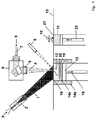
- SLM a layer of material is usually heated by means of laser irradiation on only one side of the layer, the side of the layer facing away from the beam is heated solely by heat transfer within the layer, which may be slow compared to the heating rate.
- a high temperature gradient between the two sides of the layer is the result. This may lead to evaporation, in particular explosive evaporation, on the side of the layer heated by the beam, while the side of the layer facing away from the beam may not even be molten.
- US 7,452,500 solves this problem by heating during a plurality of intervals. During the waiting period between two intervals the temperature gradient between the two sides of the layer is reduced by heat transfer, while the beam heats other regions of the layer. Thus the method avoids large temperature differences between the two sides of the layer to be melted, which avoids the risk of evaporation or even explosive evaporation of layer material due to overheating and reduces the time required to make an article. It also leads to reduced stress.
- An apparatus for free form fabrication is also disclosed in US 7,452,500 .
- the stated object is achieved by a method of producing a ceramic article comprising the steps of:
- Preferred is a method according to the invention (preferably a method characterized in this text as preferred,) wherein the powder or powder mixture consists of ceramic material.
- the method according to the present invention allows the production of a ceramic article from one or more layers of ceramic material.
- the shape of the ceramic article formed in this process can be determined by appropriate selection of the region or regions heated in step (d). In contrast to the subtractive methods no mechanical operations are necessary to determine the shape of the ceramic article.
- the shape of the layer is determined by the region or regions heated in step (d).
- the temperature at which at least a part of said powder or powder mixture melts and the temperature at which at least part of the material melted in step (d) is solidified are preferably determined by differential scanning calorimetry.
- step (e) comprises cooling said at least one region of said layer below the solidus temperature of the layer material present in said region after step (d), such that the layer is joined with said surface in said at least one region.
- any ceramic article produced by a method of the present invention which is used in a further processing step is also called "intermediate product”.
- the method according to the present invention comprises the successive repetition of steps (a), (b), (d), and (e), wherein the surface of the layer produced by a preceding series of steps (a) to (e) is used in a respective subsequent step (b) as surface for the following layer.
- the method of the invention thus allows the construction of articles with complicated shapes by joining as many layers as necessary. It avoids waste of material and is economically viable for prototype production, for the production of small series or the production of various articles wherein each article has a different shape.
- the method also allows the production of ceramic articles with complex three dimensional structures that cannot be produced by subtractive methods of production.
- the building time of the ceramic articles according to the present invention is an important factor for the determination of the commercial viability of the present process.
- Two (interdependent) parameters that influence the building time are the cycle time and the height building speed.
- a single cycle of steps (a), (b), (d), and (e) requires less than 5 minutes from the beginning of step (a) to the end of step (e), more preferably less than 2 minutes.
- Such a short cycle time is favored in order to make the process economically more viable.
- Parameters that influence the cycle time are for example the size of the area of the surface of the layer deposited in step (b) that is to be melted, the power of the energy beam and the size and the shape of the impact area of the energy beam on the layer deposited in step (b).
- the expert in the art will choose and, if necessary, optimize these parameters in order to produce the desired ceramic articles in a short time.
- the height building speed is 0.5 mm per hour or more, preferably 1.0 mm per hour or more and especially preferred 1.5 mm per hour or more.
- the height building speed is influenced by the cycle time, the thickness of the layer deposited in step (b), the time needed to deposit the powder or powder mixture in step (b) and other parameters.
- the absolute value of the linear expansion (or shortening) of the solidified layer is typically proportional to the temperature difference, in the present case proportional to the temperature difference between the solidus temperature and ambient temperature.
- the molten parts of said layer will contract considerably in length, while the dimensions of the surface will not be changed to the same extent. This leads to stresses and for example to curling and possibly to delamination of the layer from the surface.
- step (d) In case heating, (e.g. in step (d)) is applied to the surface of the layer deposited in step (b) (upper surface), the low heat transmission coefficient of ceramic materials also makes it difficult to heat the opposed surface facing away from the surface of said layer deposited in step (b) (opposed surface) as the opposed surface is heated solely by heat conduction. This leads to temperature differences between the two sides of the layer which may cause damages to the structure upon cooling.
- a further problem is the time required to heat the opposed surface. It is often desired to surface-fuse the layer deposited in step (b) with the surface on which the powder is deposited in step (b) (underlying surface). In order to fuse said upper layer deposited in step (b) with said underlying surface, said opposed surface that is in contact with the underlying surface and said underlying surface must at least partly be molten in said region. Because of low heat transmission coefficients of the ceramic materials melting of the opposed surface may take considerable time and may limit the processing speed of the present process.
- One method to increase the processing speed is to increase the power of the energy beam(s), to increase the temperature of the upper surface to temperatures higher than said maximum temperature. This increases the temperature differences between the upper surface and the opposed surface, thereby increasing the heat transmission.
- the temperature of the upper surface does preferably not exceed the boiling point of any of the components of the powder or powder mixture. Otherwise the material would merely vaporize without forming a ceramic article. The vapor would also form gas bubbles in a remaining melt pool, which after solidification could lead to a higher porosity and therefore a lower bending strength of the ceramic articles.
- Using high-energy beams does therefore usually not increase the processing speed in a satisfactory manner and introduces further problems into the process.
- the preheating temperature of step (c) is the temperature of the surface of the layer deposited in step (b) after preheating, i.e. at the time the heating in (separate) step (d) begins. Said preheating temperature is lower than said maximum temperature.
- step (d) The temperature of the powder or powder mixture at the time when heating according to step (d) starts is usually much lower than said maximum temperature, if step (c) is not performed.
- step (c) by heating a certain region of said layer in step (d) a large temperature difference is created between said region and such regions of said layer that are not heated in step (d).
- steps (d) After step (d) has ended, parts of the heated region that are close to the non-heated regions will cool down considerably faster than other parts of that region thereby creating mechanical stress and possibly damages in the region and in the whole structure of the solidified layer.
- Preheating according to step (c) can be used to alleviate temperature differences in said layer, and it therefore reduces mechanical stress and improves the physical and mechanical properties of the ceramic articles produced.
- Preheating of said layer deposited in step (b) reduces also the difference between (i) the temperature of the opposed surface at the time step (d) begins and (ii) said maximum temperature, thereby reducing heating time and increasing processing speed. If vaporization caused by overheating of the ceramic material is avoided or minimized the porosity of the ceramic article produced is reduced.
- preheating also leads to heat transfer to the surface material of the layer solidified in step (e) of the preceding cycle.
- This heat transfer may reduce the cooling rate of the layer solidified in step (e) of the preceding cycle.
- Faster cooling may lead to larger amounts of amorphous phases in the produced ceramic article.
- a decreased cooling rate will increase the amount of crystalline parts in the ceramic article, thereby increasing bending strength, fracture toughness and other physical properties of the ceramic article produced. Preheating may therefore improve the quality of the ceramic article produced.
- preheating is only performed between step (b) and step (d) only.
- Preheating is typically conducted using a preheating device.
- preheating may either end at the time heating according to step (d) starts or before heating according to step (d) starts. In the latter case, said powder or powder mixture may cool down to the preheating temperature (see the above definition) before step (d) starts.
- the preheating device used to preheat said layer in step (c) is also applied during one or more other steps of the aforementioned method.
- step (c) is conducted continuously. If steps (a) to (e) are not repeated, step (c) is beginning before step (d) and is ending after step (d). Alternatively, if steps (a) to (e) are repeated, step (c) is beginning before step (d) is conducted for the first time and is ending after step (d) is conducted for the last time.
- the method comprises the steps of:
- parts of (i) said ceramic material in said at least one region, and (ii) the ceramic article already produced are preferably only molten when heated in step (d).
- step (e) after step (e) and in case of successive repetitions of steps (a), (b), (d), and (e), after step (e) is conducted for the last time, the following step is conducted:
- preheating in step (c) is applied to the whole surface of the layer deposited in step (b).
- a method according to the present invention as aforementioned, wherein continuous preheating is applied to the whole surface of said layer deposited in step (b) and to the whole surface of the ceramic article already produced that is not covered by said layer deposited in step (b).
- a further preferred method according to the present invention is therefore a method as described herein, wherein the preheating is applied continuously during the whole process of producing said ceramic article by infrared irradiation or resistance heating to the whole surface of said layer deposited in step (b) and to the part of the ceramic article already produced.
- step (d) is conducted for the first time and ending after step (d) is conducted for the last time and even more preferably throughout the whole production process.
- a very preferred method of producing a ceramic article comprises the steps of:
- a method of the present invention wherein only the powder or powder mixture, said layer and/or said surface is heated in step (c).
- a reaction chamber is used for producing said ceramic article.
- the whole or parts of the reaction chamber used for the production of the ceramic article are preheated continuously by infrared irradiation or resistance heating.
- the whole chamber and its content or parts thereof is kept continuously at a high temperature so that large differences in temperature during the production process can be avoided.
- the preheating temperature is less than 1200°C, preferably less than 1050°C.
- preheating of the whole chamber or parts thereof involves a complex and costly apparatus, as all machinery used and all parts of the chamber that are preheated have to be able to withstand high temperatures for an extended period of time.
- step (c) if step (c) is conducted, the energy for preheating in step (c) is directed to the surface of said layer. This allows to define exactly the location the energy is applied to and to apply it close to the location where heating is required. Unnecessary or undesired heating of parts of the apparatus or undesired melting of the parts of the ceramic article already produced can be largely avoided.
- step (c) is conducted, further preferred is a method according to the present invention (more preferably according to any method according to the present invention characterized herein as preferred,) wherein in step (c) the layer is preheated by means of an energy beam or a plurality of energy beams.
- Energy beams can provide a large amount of energy in a short time and are well suited to apply energy to the surface of a solid, as they do not or not to a relevant extent interfere with gas, but can be absorbed by the surface of solids. They are also able to provide a well defined amount of energy to a well defined location with a high energy density, i.e. a well defined, high amount of energy per surface area.
- step (c) by preheating (irradiating) once or a plurality of times in step (c) and heating in step (d) so that heat transfer from the irradiated (hot) to the opposed (cold) side of the layer can occur within the respective region of the layer of material during a period or those periods, i.e. after a given preheating treatment in step (c), in which the surface of said region is not irradiated.
- the energy beam or energy beams can be used to heat or preheat other regions of the layer or other layers. After said period wherein said region is not being irradiated, the beam is redirected to the region to continue and/or complete the preheating process or to conduct step (d).
- the duration of the irradiation of a plurality of regions of the layer is significantly reduced.
- This alternating irradiation also allows the beam source, e.g. a laser or electron beam source, to be higher powered, thus allowing a greater amount of energy to be delivered to the respective position per time.
- the risk of explosive vaporization of these particles of material is considerably reduced by directing the beam to a different position after a short period.
- a method according to the present invention (more preferably according to any method according to the present invention characterized herein as preferred,) wherein one, two, a plurality or all regions of said layer are preheated in step (c) and are also heated in step (d).
- This method also reduces mechanical stress through rapid heating and cooling processes and reduces the risk of explosive vaporization as mentioned above.
- especially preferred is therefore a method according to the present invention, wherein all regions of said layer heated in step (d) are preheated in step (c).
- an area of said layer is preheated that comprises all regions heated in step (d).
- the ceramic article is prepared by heating and melting of at least one region each of a plurality of parallel layers of a powder or powder mixture and joining of the melt with the respective underlying surface in order to build up a ceramic article by successive repetition.
- the combined heating area is therein the area on the surface provided in step (b) consisting of the orthogonal parallel projection of all regions of said layers heated in the first step (d) and in all successive repetitions of step (d) on the surface provided in step (b).
- Preferred is a method according to the present invention, wherein at least the combined heating area is preheated in step (c).
- a method according to the present invention comprising the successive repetition of steps (a), (b), (c), (if preheating is not continuous, as discussed above) (d), and (e) and wherein the surface of the layer produced by a preceding series of steps (a) to (e) is used in a respective subsequent step (b) as surface for the following layer and wherein at least the combined heating area is preheated in step (c).
- This method allows preheating of every region heated in the first step (d) and every repetition of step (d) by a preheating device that is directed to a constant area during the whole production of the ceramic article. Adaption of the preheating device to the various regions heated in step (d) in various layers is not necessary, which simplifies preheating.
- step (c) said at least one region is preheated by one or more laser beams, preferably laser beams of a laser selected from the group consisting of CO 2 -laser, Nd: YAG-laser, fiber laser and diode laser, wherein it is further preferred that said laser beam is defocused.
- Laser beams may have a circular or non-circular laser beam.
- Defocused laser beams according to the present invention preferably have an impact area on the surface of said layer deposited in step (b) (hereinafter called "effective impact area") of more than 0.196 mm 2 (equivalent to the area of a circle with a diameter of 500 ⁇ m), more preferably of 0.786 mm 2 (equivalent to the area of a circle with a diameter of 1000 ⁇ m) or more.
- Defocused laser beams used for the preheating of large parts or more than half of the surface or the whole of the surface of said layer deposited in step (c) preferably have an impact area on the surface of said layer deposited in step (b) (hereinafter called "effective impact area") of more than 1 cm 2 , more preferably of 5 cm 2 or more and even more preferably of 10 cm 2 or more.
- defocused laser beams that have an impact area that can cover a square area on the surface of said layer deposited in step (b) of 30 mm x 40 mm.
- Said effective impact area is herein defined as the area (circle if a circular laser beam is used) to which 86 % of the power of the laser beam is applied.
- Preferred according to the present invention are defocused laser beams with a Gaussian profile or a beam profile with a high edge steepness and an otherwise homogenous beam profile, corresponding to a (preferred) homogeneous intensity over the irradiated area.
- the method according to the present invention includes a preheating step (c) wherein in step (c) one, two, a plurality or all regions are preheated.
- a method according to the present invention (more preferably according to any method according to the present invention characterized herein as preferred,) wherein in step (c) said energy beam or said plurality of energy beams is directed to one, two, a plurality or all regions of said layer in a predetermined exposure pattern.
- a method according to the present invention wherein the whole surface or at least 50% of the surface of said layer deposited in step (b) is preheated by a preferably defocused homogenous laser beam and wherein the difference in temperature between different preheated regions of the surface of said layer deposited in step (b) is preferably 300°C or less, preferably 150°C or less and especially preferred 50°C or less.
- the homogeneous laser beam is thereby preferably produced by use of a homogenization device in order to homogenize the intensity distribution of the laser beam.
- a homogenization device Especially preferred is the use of diffractive optical structures as homogenization device.
- a defocused homogeneous (CO 2 -)laser beam is used in step (c) to preheat at least the combined heating area and preferably the whole surface and wherein the defocused laser beam is applied continuously during the whole process of producing said ceramic article until step (d) and preferably until step (e) is performed for the last time.
- heating and, if appropriate, preheating is conducted such that the powder or powder mixture in some or all regions that are not heated in step (d) (whether heated in step (c) or not) does not sinter or at least does not sinter to an extent that makes recycling for further use as powder or powder mixture in a method of the present invention impossible.
- heating and, if appropriate preheating is conducted such that that the powder or powder mixture in some or all regions that are not heated in step (d) (whether heated in step (c) or not) is not changed in its relevant chemical or physical properties, especially not changed in chemical composition, particle size and/or flow characteristics. This allows the recycling of the powder or powder mixture and contributes to the commercial viability of the method.
- step (b) the amount of energy per volume and time or the amount of energy per surface area and time applied to at least one region of said layer provided in step (b) differs for least one period of time during preheating in step (c) from the amount of energy per volume and time or the amount of energy per surface area and time, respectively, applied to the same region of said layer provided in step (b) during heating in step (d).
- preheating in step (c) is performed by a defocused energy beam and heating in step (d) is performed by a focused energy beam.
- preheating in step (c) is performed by a defocused laser beam or a microwave beam and heating in step (d) is performed by a focused laser beam.
- preheating in step (c) is performed by a defocused laser beam and heating in step (d) is performed by a focused laser beam.
- said powder or powder mixture comprises components that form an eutectic system with each other.
- Eutectic systems have a lower melting point than any of their constituents. The presence of a eutectic system in said powder or powder mixture may therefore reduce the temperature necessary to melt said layer, and therefore a reduced maximum temperature may be used in step (d). A reduced temperature leads to reduced temperature differences and therefore to advantageous physical properties of the ceramic articles, as discussed in other parts of the present text. It leads especially to a reduction in the amount of cracks, fissures and other damages. Eutectic systems also have a higher difference between melting (liquidus) temperature and evaporation temperature, thereby lowering the risk of evaporation, as discussed above.
- Particular preferred is a method of producing a ceramic article comprising the steps of:
- said powder or powder mixture comprises components that form an eutectic system with each other.
- an eutectic system is a group of compounds, wherein the equilibrium phase (melt) diagram of a mixture consisting of all compounds of this group has an eutectic point.
- An eutectic mixture has the mixing ratio of the components of an eutectic system at the eutectic point.
- a method according to the present invention which comprises one ore more repetitions of steps (a) to (e), wherein the surface of the layer produced by each preceding series of steps (a) to (e) is used in a respective subsequent step (b) as surface for the following layer.
- the preheating temperature is lower than the liquidus temperature, preferably lower than the solidus temperature of said ceramic material. In a further preferred method according to the present invention, (preferably a method characterized in this text as preferred,) the preheating temperature is lower than said maximum temperature.
- step (d) heating is conducted such that all components of said eutectic system are present in the melt.
- the maximum temperature is higher than the melting point of the highest melting component of the eutectic system.
- step (d) heating is conducted such that all components of said eutectic system are present in the melt and wherein in step (e) at least a part of the components of the eutectic system in the melt crystallizes as eutectic mixture.
- step (e) at least a part of the components of the eutectic system in the melt crystallizes as eutectic mixture.
- This can for example be achieved by providing a powder or powder mixture with a high proportion of the compounds of the eutectic system and by providing a powder or powder mixture, wherein the compounds of the powder or powder mixture that are part of the eutectic system are present in a weight ratio that is similar to their weight ratio in the eutectic mixture.
- the crystallization of eutectic mixtures leads to very fine crystals in the crystallized layer and therefore to ceramic articles with a high bending strength and a high fracture toughness and other improved physical properties.
- the fraction by weight of the component is at least 25 %, preferably at least 50 %, especially preferred at least 70 % and most preferred at least 90 % of the fraction by weight of the same component in the eutectic mixture of said eutectic system.
- a melted mass of an eutectic mixture crystallizes in very fine crystals often of a size of 1 ⁇ m or less.
- the crystals are typically much smaller than crystals that derive from crystallization of non eutectic mixtures. This leads to a dense and homogeneous packing of crystals in the ceramic article and an improvement of the bending strength, hardness and smoothness of the surface, fracture toughness, fracture strength, biocompatibility and to a reduction of the overall pore volume.
- the melting and freezing temperature of eutectic mixtures are lower than those of the single components, so that said maximum temperature can be lowered and formation of cracks, fissures and other damages is reduced.
- At least 50 percent by weight, preferably at least 70 percent by weight of said powder or powder mixture consist of one or more compounds selected from the group consisting of Al 2 O 3 , ZrO 2 , Y 2 O 3 , Na 2 O, Nb 2 O 5 , La 2 O 3 , CaO, SrO, CeO 2 , MgO, TiO 2 , Cr 2 O 3 , CuO, the mixed oxides thereof, especially MgAl 2 O 4 , SiC, TiC, Si 3 N 4 and AIN.
- a method according to the present invention (more preferably according to any method according to the present invention characterized herein as preferred,) wherein at least 50 percent by weight, preferably at least 70 percent by weight of said powder or powder mixture consist of one or more oxides selected from the group consisting of ZrO 2 , Al 2 O 3 , MgO, Y 2 O 3 , Cr 2 O 3 , Na 2 O, TiO 2 , La 2 O 3 , and the mixed oxides thereof, especially MgAl 2 O 4 .
- a method according to the present invention (more preferably according to any method according to the present invention characterized herein as preferred,) wherein said powder or powder mixture comprises ZrO 2 and Al 2 O 3 .
- said powder or powder mixture comprises ZrO 2 and Al 2 O 3 .
- at least 50 percent by weight and more preferably at least 70 percent by weight of said powder or powder mixture consist of ZrO 2 and Al 2 O 3 .
- step (d) If an eutectic mixture of Al 2 O 3 and ZrO 2 is comprised in said powder or powder mixture, part of the Al 2 O 3 may evaporate during the process in particular in step (d)) such that during step (e) and in the final product the proportion of Al 2 O 3 relative to ZrO 2 may be smaller than in the eutectic mixture. It may therefore be necessary to provide a powder or powder mixture in step (a) that has a higher proportion of Al 2 O 3 relative to ZrO 2 than the eutectic mixture of the two components, in order to consider evaporation. The same applies to other eutectic systems.
- Al 2 O 3 is present in an amount in weight percent that is higher than in the eutectic mixture, preferably up to 7.5 % by weigth or about 7.5 % by weigth based on the overall amounts of Al 2 O 3 and ZrO 2 higher than in the eutectic mixture.
- the eutectic mixture of Al 2 O 3 and ZrO 2 consists of 42.6 percent by weight of ZrO 2 and 57.4 percent by weight of Al 2 O 3 .
- a preferred method according to the present invention is a method, wherein said powder or powder mixture comprises ZrO 2 and Al 2 O 3 , and wherein the mixing ratio by weight of ZrO 2 to Al 2 O 3 is in the range of from 30:70 to 42.6:57.4, preferably of from 35:65 to 42.6:57.4 and especially preferred in the range of from 39:61 to 42.6:57.4.
- a method according to the present invention preferably as characterized herein before (more preferably according to any method according to the present invention characterized herein as preferred,) wherein said powder or powder mixture comprises ZrO 2 and Al 2 O 3 , and wherein the mixing ratio by weight of ZrO 2 to Al 2 O 3 is 42.6 to 57.4 (eutectic mixture).
- a method according to the present invention (more preferably according to any method according to the present invention characterized herein as preferred,) wherein said powder or powder mixture consists of 42.6 percent by weight of ZrO 2 and 57.4 percent by weight of Al 2 O 3 , i.e. which consists of the eutectic mixture.
- said ceramic article produced comprises or consists of material that has superplastic properties at elevated temperature.
- Ceramic articles with superplastic properties prepared by a process according to the present invention alleviate tensile stress through superplastic deformation and develop therefore less or repair cracks, fissures and other damages.
- Superplastic properties can be expressed by a strain-rate-sensitivity-parameter m as disclosed in Dirks-Eicken in "Schsuchungen zur Superplastizmaschine von Al2O3-ZrO2-Keramiken", Fort suitssberichte VDI, Grund- und Maschinentechnik Nr. 343, VDI-Verlag GmbH, Düsseldorf, 1994 , especially page 55 and the documents cited therein.
- step (e) Especially preferred is a method according to the present invention (more preferably according to any method according to the present invention characterized herein as preferred,) wherein the material or at least part of the material solidified in step (e) has an m value maximum in the temperature range of from 1350°C to 1500°C of at least 0.5, preferably of at least 0.75.
- a method according to the present invention wherein said powder or powder mixture comprises components that form an eutectic system with each other, may therefore yield ceramic articles consisting of material with superplastic properties, thereby reducing cracks, fissures and other damages and improving the physical properties, of the final products.
- Mixtures of Al 2 O 3 and ZrO 2 show superplastic properties at high temperatures.
- the superplastic properties of mixtures of Al 2 O 3 und ZrO 2 are enhanced by addition of MgO, SiO 2 , Spinell (MgAl 2 O 4 ) or Mullite (SiO 2 -Al 2 O 3 ).
- a method according to the present invention (more preferably according to any method according to the present invention characterized herein as preferred,) wherein said powder or powder mixture comprises ZrO 2 and Al 2 O 3 and one or more compounds selected from the group consisting of MgO, SiO 2 , Spinell (MgAl 2 O 4 ) and Mullite (SiO 2 -Al 2 O 3 ).
- MgO is preferably present in an amount of up to 5%.
- SiO 2 is preferably present in an amount of up to 5%.
- Spinell (MgAl 2 O 4 ) is preferably present in an amount of up to 35%, and Mullite (SiO 2 -Al 2 O 3 ) is preferably present in an amount of up to 25%.
- the (efficient) relief of tensile stresses through superplasticity is a process that requires a certain amount of time. If the melt is crystallized and cooled in step (e) at a very fast rate to below the temperature that is required for an efficient relief of tensile strength through superplasticity, cracks, fissures and other damages may occur in the ceramic article. Therefore all measures that lead to higher temperatures in the surrounding materials and thereby lead to slower cooling of the layer solidified in step (e) may lead to an extension of the time where the layer solidified in step (e) is in the temperature range that allows superplastic deformation. This in turn may improve the physical properties such as the bending strength of the final ceramic article.
- preheating may be performed in step (c). Preheating also leads to heat transfer to the surface material of the layer solidified in step (e) of the preceding cycle. This heat transfer may keep the temperature of the layer deposited in the previous cycle for a longer time in the temperature range that allows for an efficient relief of tensile stress by means of superplastic deformation. This is especially true if the preheating is applied continuously during the whole process of producing said ceramic article. Preheating of said powder or powder mixture before step (b) to a powder preheating temperature or preheating of said surface before step (b) and/or heating and/or insulation of the reaction chamber as discussed below may have a similar effect.
- the method according to the present invention is performed in air.
- an inert gas is used.
- air sensitive components are carbides and nitrides.
- An inert gas may also be used if parts of the apparatus are sensitive to air under the conditions of the process or for other reasons.
- An example for an air sensitive part of the apparatus is a scraper consisting of or including carbon fiber material.
- step (b) deposition of a powder of powder mixture in step (b) with a high temperature difference to the material of a region of the layer of the previous (preceding) cycle causes a temperature shock to the material of a region of the layer of the previous cycle leading to rapid cooling and in turn to cracks, fissures and other damages.
- said powder or powder mixture is preheated before step (b) by means of an energy radiation, preferably by means of microwave radiation or infrared radiation or a radiant heater.
- a method according to the present invention (more preferably according to any method according to the present invention characterized herein as preferred,) wherein in step (b) the surface and said powder or powder mixture being deposited on the surface have the same temperature.
- step (b) the surface and said powder or powder mixture being deposited on the surface have the same temperature.
- step (b) the whole procedure is performed in an apparatus comprising a chamber which comprises the powder or powder mixture to be used in step (b), the originally provided surface, and the ceramic article (intermediate product) so far produced (by repetition of steps (a) to (e)), and wherein the whole chamber and its content are preheated to said same temperature.
- the cooling rate of the layer after crystallization in step (e) is a relevant parameter in the method according to the present invention.
- a fast cooling process favors formation of small crystals in the crystallized layer, which improves the properties of the final product.
- relevant superplasticity, sintering and diffusion is only observed above a certain temperature, and the (efficient) relief of tensile strength through superplasticity, sintering and diffusion is a process that requires a certain amount of time. If the melt is crystallized and cooled in step (e) at a very fast rate to below the temperature that is required for the relief of tensile strength through superplasticity, sintering and/or diffusion, cracks, fissures and other damages may occur in the ceramic article.
- the layer is kept at a high temperature over a longer period of time, sintering and/or re-crystallization will occur on a disadvantageous scale.
- the expert in the art will therefore optimize the temperature of the layer already produced such that re-crystallization is diminished while relief of tensile strength through superplasticity is still possible.
- the choice of temperature or temperature range depends on the materials used. Examples are given below. For further materials the expert will establish suitable temperatures by means of preliminary tests which include measuring and optimizing the superplasticity of the material and the bending strength or other parameters of the products.
- a method according to the present invention (more preferably according to any method according to the present invention characterized herein as preferred,) wherein said energy beam or at least one energy beam of said plurality of energy beams used in step (d) is a focused energy beam, preferably a focused laser beam of a CO 2 -laser or a Nd: YAG-laser or a focused electron beam. Most preferred are focused laser beams of CO 2 -lasers or Nd: YAG-lasers.
- Focused laser beams according to the present invention preferably have an effective impact area of 0.196 mm 2 or less (equivalent to the area of a circle with a diameter of 500 ⁇ m), more preferably of 0.0314 mm 2 (equivalent to the area of a circle with a diameter of 200 ⁇ m) or less.
- the diameter of a circular focus is therein defined as aforementioned.
- Preferred according to the present invention are focused laser beams with a Gaussian profile or a top-hat intensity distribution.
- the necessary amount of overlap depends on the material used, the geometry of the ceramic article, the cycle time and various other parameters. There may be no overlap necessary or the overlap may be up to half of the width of the tracks produced or even more than that.
- the expert in the art will determine by preliminary experiments, how much overlap is necessary to achieve the desired properties in the ceramic article (e.g. bending strength and the like).
- one method according to the present invention is a method wherein said region in step (d) is not completely melted so that such interfaces are established.
- step (d) is a method according to the present invention (more preferably according to any method according to the present invention characterized herein as preferred,) wherein in step (d) the powder or powder mixture in said region is completely melted throughout the entire thickness of said layer.
- step (d) the powder or powder mixture in said region is (completely) molten and the resulting melt is heated to a temperature that is in the range of from 1.025 to 1.5 times, preferably of from 1.05 to 1.25 times, the temperature in Kelvin of the highest melting component of said powder or powder mixture.
- step (d) the material of the surface said powder or powder mixture is deposited on in step (b) is partly or completely molten. If the material of said surface is partly or completely molten, the material of said surface and the melt pool(s) derived from melting said regions in step (d) mix with each other. When cooled below their solidus point or melting point, said surface and the molten regions of the layer deposited in step (b) are fused to form one solid ceramic body.
- the material of the surface said powder or powder mixture is deposited on in step (b) is partly or completely molten by heat transfer from the surface of the layer deposited in step (b).
- a method according to the present invention (more preferably according to any method according to the present invention characterized herein as preferred,) wherein said powder or powder mixture comprises or consists of particles selected from the group consisting of primary particles, agglomerates, or mixtures thereof.
- a method according to the present invention (more preferably according to any method according to the present invention characterized herein as preferred,) wherein said powder or powder mixture comprises or consists of agglomerates obtained or obtainable by spray drying or powder jetting.
- a method according to the present invention (more preferably according to any method according to the present invention characterized herein as preferred,) wherein said powder or powder mixture comprises or consists of primary particles prepared by grinding, solidification from gas phase or dense sintering of agglomerates obtained or obtainable by spray drying or powder jetting.
- dense sintered agglomerates are prepared by sintering agglomerates consisting of agglomerated units of two or more primary particles in a rotating oven.
- the process is controlled such that the agglomerated units sinter to form particles (dense sintered agglomerates) that resemble primary particles or are identical to primary particles in structure and/or form, while the agglomerated units do not or not to a large extent sinter with each other to form larger units.
- a method according to the present invention (more preferably according to any method according to the present invention characterized herein as preferred,) wherein said powder or powder mixture consists of particles with a d 50 particle size in the range of from 1 to 100 ⁇ m, preferably in the range of from 15 to 70 ⁇ m.
- the size of the particles has a prominent influence on the minimum thickness of said layer in step (b). If the particle size and therefore the thickness of said layer is too large, and the layer is primarily heated from its surface, melting of the opposed side facing away from the surface will be very slow and melting may be impossible without overheating the surface of said heated region of said layer that is heated which may result in loss of layer material through evaporation. Mixing of viscous melts is difficult and time consuming. Small particles in the stated range allow for a homogeneous melt and do therefore improve the properties of the final product. Throughout this document, if not otherwise mentioned, the particle size of the powder or powder mixture is determined by laser diffraction using a coulter counter.
- a method according to the present invention (more preferably according to any method according to the present invention characterized herein as preferred, wherein said powder or powder mixture is a bimodal or a multimodal powder mixture.
- Bimodal and multimodal powder mixture allow for a high packing density which prevents entrapment of gases and the like in the melt.
- a method according to the present invention (more preferably according to any method according to the present invention characterized herein as preferred,) wherein said powder or powder mixture is a bimodal powder mixture and the particles of a first fraction have a d 50 particle size in the range of from 1 to less than 15 ⁇ m, and the particles of a second fraction have a particle size in the range of from 15 to 100 ⁇ m.
- Bimodal powder mixtures for use in the present invention are for example prepared by mixing of two powders with a different grain size distribution.
- grain size and shape of the powder or powder mixture also influences flowability. If flowability is too low, deposition of a layer of said powder or powder mixture in step (b) and especially deposition of a uniform layer, which is preferred according to the present invention, is sometimes difficult. Preferred is therefore a method according to the present invention, (more preferably according to any method according to the present invention characterized herein as preferred,) wherein said powder or powder mixture has a flowability of at least 4, preferably at least 7.
- Spherical particles have a better flowability than non-spherical particles.
- Sphericity is a measure of how spherical (round) an object is.
- the sphericity of a given particle is defined as the ratio of the surface area of a sphere (with the same volume as the given particle) to the surface area of the particle.
- Preferred is a method according to the present invention (more preferably according to any method according to the present invention characterized herein as preferred,) wherein the particles of said powder or powder mixture have an average sphericity of 0.8 or more, preferably of 0.9 or more.
- the roundness of the particles is measured.
- Roundness is the average ratio of the square of the circumfence and the area of the two-dimensional image of the particles. Roundness can conveniently be measured by digital image processing with a CAMSIZER of the company Retsch Technology GmbH, Haan. A circle has a roundness of 12.57 and a square has a roundness of 16.
- Preferred is a method according to the present invention, preferably as characterized herein before as preferred, wherein the particles of said powder or powder mixture have a roundness of 16 or less, preferably of 15 or less, more preferably of 14 or less and most preferably of 13 or less.
- some of the particles in the powder or powder mixture may have a different chemical composition than others.
- This allows for a simple preparation of said powder or powder mixture and a simple determination of the final composition of the layer by simple mixing of separate powders of different compounds.
- Preferred is however a method according to the present invention (more preferably according to any method according to the present invention characterized herein as preferred,) wherein at least a part and preferably all of the particles of said powder or powder mixture have the same chemical composition.
- This provides a melt and in turn a crystallized layer which is very homogeneous, as convection and/or diffusion over long distances are not required for intensive mixing of the components. It is preferred that at least 30 % by weight, more preferably at least 60 % by weight and most preferred 90 % by weight of said powder or powder mixture consists of particles that have the same chemical composition.
- Powders wherein at least a part or all of the particles of said powder or powder mixture have the same chemical composition can for example be prepared by spray drying of solutions containing different compounds.
- a further method is the use of a method where small drops of a mixture of powder, water and binder are produced and dried or hardened. The small particles produces are then dried at elevated temperatures.
- a further method is the precipitation of powders of mixed oxides from a solution of the constituents. The powder produced may then be processed further by spray drying or other methods. Powders with crystalline spherical particles of defined particle sizes can be produced by rapid cooling of gaseous materials.
- the thickness of said layer deposited in step (b) has a strong influence on the quality of the final products and the commercial viability of the process.
- the thickness of the layer influences the time and energy required for the melt process in step (d). Since thin layers allow for a fast melting process, they are preferred for the purposes of step (d), however, if thin layers are used, the build-up of a large number of layers may be required to produces a ceramic article.
- the thickness of the layer is about the same size as the average particle diameter, not all parts of said surface may be covered by said powder or powder mixture, resulting in an uneven application of the layer and direct heating of the surface on which the powder or powder mixture is deposited in step (b). Thick layers have the opposite effects.
- step (b) has a thickness in the range of from 5 to 200 ⁇ m, preferably in the range of from 20 to 70 ⁇ m.
- Said layer deposited in step (b) may have the same layer thickness in every cycle or the layer thickness may be varied depending on the complexity of the patterns for melting and curing and/or the amount of geometric differences between subsequent layers. If, for instance, the patterns for melting and curing for a multitude of subsequent layers is identical, then the total building time can be reduced by increasing the layer thickness without loss of precision.
- step (b) but before step (d) or (c), respectively, said layer is mechanically compressed.
- Mechanically compressed layers of said powder or powder mixture contain less hollow space which leads to ceramic article with less porosity.
- Mechanically compressed layers of said powder or powder mixture are also more uniform in thickness.
- a uniform thickness of said layer is important, because an adjustment of the amount of power provided by the energy beams to the thickness of the layer is difficult or at least complex and costly. Therefore, in a typical method of the present invention in step (c) and in step (d) the energy beams provide the same amount of energy to all regions to be preheated or heated.
- step (b) if steps (a) to (e) are repeated this holds for one, two, more or all steps (b) of the complete process) but before step (d), or if step (c) is conducted before step (c), said layer deposited in step (b) is leveled to a desired layer thickness, preferably by passing a leveling device over the shaped body once, two, three or more times.
- steps (a) to (e) either compression or leveling may be performed or both may be performed simultaneously or one after the other.
- Tetragonal stabilised ZrO 2 has been established as a useful material for producing ceramic articles. When cooling a melt of ZrO 2 it crystallizes as cubic ZrO 2 and upon further cooling transforms into tetragonal ZrO 2 and monoclinic ZrO 2 . It is known that the volume expansion caused by the subsequent transformations may cause damages to a ceramic article. Certain oxides have been used to stabilize the cubic and/or the tetragonal phase.
- ZrO 2 stabilizes the tetragonal phase of ZrO 2 , thereby reducing the volume expansion of the ZrO 2 which reduces mechanical stress, cracks, fissures and other damages in the ceramic article.
- a method according to the present invention (more preferably according to any method according to the present invention characterized herein as preferred,) wherein said powder or powder mixture comprises ZrO 2 and at least one component selected from the group consisting of Y 2 O 3 , CeO 2 and MgO and wherein the amount of the component or components selected from said group is preferably sufficient to stabilize at least 50 % by volume, preferably at least 75 % by volume of the ZrO 2 in the final article in the tetragonal form and wherein, if selected, in particular if selected as sole component from the group, the amount of Y 2 O 3 is preferably in the range of 1 to 7 percent by weight, the amount of CeO 2 is preferably in the range of 5 to 15 percent by weight and the amount of MgO is preferably in the range of 3 to 10 percent by weight based on the amount of ZrO 2 .
- a method according to the present invention (more preferably according to any method according to the present invention characterized herein as preferred,) wherein in said ceramic article at least 50 percent by volume and preferably at least 75 percent by volume of the total volume of ZrO 2 in the article is tetragonal stabilized, doped ZrO 2 .
- a treatment for improving bending strength is performed.
- the treatment for improving bending strength is preferably a surface roughness reducing step, preferably selected from the group consisting of machining (polishing, grinding, sand-blasting) and surface coating (veneering etc).
- a method according to the present invention (more preferably according to any method according to the present invention characterized herein as preferred,) wherein, if steps (a) to (e) are not repeated, after step (e), or if steps (a) to (e) are repeated, after the final repetition of steps (a) to (e), a thermal treatment or glass-infiltration of the intermediate product as obtained after final step (e) is performed.
- the thermal treatment preferably is an "annealing treatment" (i.e. a treatment at a temperature below sintering temperature).
- An aspect of the present invention relates to a method according to the present invention, preferably according to any method according to the present invention characterized herein as preferred,) of producing a ceramic article comprising the steps of:
- a method according to the present invention (more preferably according to any method according to the present invention characterized herein as preferred,) wherein, if steps (a) to (e) are not repeated, after step (e), or if steps (a) to (e) are repeated, after the final repetition of steps (a) to (e), a glass-infiltration of the intermediate product obtained is performed under process conditions which are selected such that less than 5 % by weight of the intermediate product is dissolved in the glass used for glass infiltration.
- process conditions which are selected such that less than 5 % by weight of the intermediate product is dissolved in the glass used for glass infiltration.
- glass infiltration temperature and time are carefully controlled.
- the amount of the material of the intermediate product dissolved in the glass used for glass infiltration is for the purposes of the present invention measured by energy-dispersive X-ray spectroscopy.
- a method according to the present invention (more preferably according to any method according to the present invention characterized herein as preferred,) wherein, if steps (a) to (e) are not repeated, after step (e), or if steps (a) to (e) are repeated, after the final repetition of steps (a) to (e), a glass-infiltration of the intermediate product obtained is performed under conditions and, in particular, at a temperature and for a time interval such that more than 60 %, preferably more that 80 % and most preferably more than 95 % of the pores of the intermediate product are closed.
- High effective porosity also called open porosity
- Porosity and effective porosity can be measured by image analysis of cross-sections of the ceramic articles produced and other methods. Effective porosity can also be measured by the water saturation method, mercury intrusion porosimetry and other methods. For the purposes of the present invention effective porosity is measured according to the water saturation method as disclosed in the norm ISO/FDIS 18754.
- a method according to the present invention (more preferably according to any method according to the present invention characterized herein as preferred,) wherein, if steps (a) to (e) are not repeated, after step (e), or if steps (a) to (e) are repeated, after the final repetition of steps (a) to (e) a glass-infiltration of the intermediate product obtained is performed under conditions, in particular at a temperature and for a time interval such that the bending strength of the ceramic article has a higher value after glass infiltration than the intermediate product.
- a method according to the present invention (more preferably according to any method according to the present invention characterized herein as preferred,), in particular, when air sensitive components are comprised in the intermediate product (see above) or in the glass used for glass infiltration, wherein the glass infiltration is performed under inert (protective) gas or in a vacuum.
- the latter method is especially preferred, as it allows for a very significant reduction of the effective porosity.
- a method according to the present invention (more preferably according to any method according to the present invention characterized herein as preferred,) wherein, if steps (a) to (e) are not repeated, after step (e), or if steps (a) to (e) are repeated, after the final repetition of steps (a) to (e) a glass-infiltration of the intermediate product obtained is performed with a glass which comprises or consists of at least one compound selected from but favorably all compounds of the group consisting of ZrO 2 , SiO 2 , B 2 O 3 , Al 2 O 3 , Li 2 O and CaO.
- a method according to the present invention (more preferably according to any method according to the present invention characterized herein as preferred,) wherein, if steps (a) to (e) are not repeated, after step (e), or if steps (a) to (e) are repeated, after the final repetition of steps (a) to (e) a glass-infiltration of the intermediate product obtained is performed with a glass consisting of 15 to 25 percent by weight SiO 2 , 20 to 30 percent by weight B 2 O 3 , 30 to 40 percent by weight Al 2 O 3 , 10 to 20 percent by weight Li 2 O, 2.5 to 7.5 percent by weight CaO, 0 to 3 percent by weight ZrO 2 , and optionally further oxides, wherein all percent by weight data are based on the total weight of the glass.
- a method according to the present invention (more preferably according to any method according to the present invention characterized herein as preferred,) wherein, if steps (a) to (e) are not repeated, after step (e), or if steps (a) to (e) are repeated, after the final repetition of steps (a) to (e) a glass-infiltration of the intermediate product obtained is performed, such that said ceramic article after glass infiltration has a bending strength of at least 25MPa, preferably of at least 250MPa and more preferably of at least 500MPa.
- the bending strength is measured according to the norm DIN EN 843-1.
- said ceramic article is produced on a surface which is part of a substrate.
- a method wherein said ceramic article is produced on a substrate comprising a support means and/or a connector (e.g. connecting the support means to the body of the apparatus used).
- a method according to the present invention wherein the support means or the connector has a predetermined breaking point to facilitate the separation of said ceramic article.
- the surface according to step (b) is part of the support means or the connector. In case the substrate is used with support means and a connector, the surface according to step (b) is preferably part of the support means.
- a method according to the present invention preferably as characterized herein before (more preferably according to any method according to the present invention characterized herein as preferred,) wherein the energy beam, in particular its intensity (power), focus, pathway, speed and/or the like is controlled and guided by a computer system.
- a computer system uses data from sampling (sample scanning), a CAD/CAM system or the like.
- a method according to the present invention (more preferably according to any method according to the present invention characterized herein as preferred,) wherein the temperature of the surface of said layer is at least once measured by a pyrometer.
- a method according to the present invention (preferably according to any method according to the present invention characterized herein as preferred,) wherein the temperature of the surface of said layer is at least once measured (preferably by means of a pyrometer) during step (c).
- the data corresponding to the measured temperature are used for process monitoring and/or process control, preferably using a computer (see above).
- grain sizes in solid bodies are measured by the linear intercept method according to DIN EN 623-3.
- a method wherein said ceramic article produced contains grains of optionally doped ZrO 2 and wherein the average grain size of said grains of ZrO 2 is less than 0.5 ⁇ m.
- the present invention provides a free form process for the production of ceramic articles with superior properties, like bending strength, hardness and smoothness of the surface, fracture toughness, fracture strength, biocompatibility, low overall pore volume and the like.
- a method according to the present invention (more preferably according to any method according to the present invention characterized herein as preferred,) wherein said ceramic article has a bending strength of at least 25MPa, preferably of at least 250MPa and more preferably of at least 500MPa.
- a method according to the present invention (more preferably according to any method according to the present invention characterized herein as preferred,) wherein the fracture toughness of said ceramic article is at least 4MPa*m 1/2 , preferably at least 6 MPa*m 1/2 .
- the fracture toughness is measured according to the method described in K.M. Liang et al, "Evaluation by indentation of fracture toughness of ceramic materials",Journal of Materials Science 25 (1990) 207-214 , item 3.2 and the literature cited therein.
- the fraction of the glass phase is determined by powder diffraction (XRD).
- XRD powder diffraction
- the method according to the present invention provides superior ceramic articles by rapid production of prototypes in a timely and cost effective manner.
- a method according to the present invention (more preferably according to any method according to the present invention characterized herein as preferred,) wherein a plurality of articles is produced in parallel.
- a plurality of surfaces according to step (b) are preferably arranged in an array format.
- all surfaces are in the same (horizontal) plane.
- layers of said powder or powder mixture is preferably deposited on all surfaces in one production step and heating is provided to all layers of said powder or powder material in said plain. Heating of the plurality of layers (in the same place) may be conducted simultaneously, serially or intermittently.
- a single apparatus is able to produce a plurality of articles in little more time (cycle time) than is necessary for the production of a single article.
- This approach makes the present invention more cost effective than conventional subtractive methods, in which an apparatus may only produce a single article at a given time.
- the present invention allows for the cost effective production of small batch series of identical ceramic articles, for example for the ceramic industry, and it allows for the production of individual articles that have the same composition, a similar size, but a different shape.
- dental articles such as a crown, a bridge, an inlay, an onlay or abutments
- dental articles such as a crown, a bridge, an inlay, an onlay or abutments
- articles for the electronic industry where, for example, similar but not identical articles have to be produced to be able to analyze the change of a property of the articles corresponding to a change in the shape.
- said ceramic article is a dental article, in particular a dental restoration or frame.
- said ceramic dental article is a crown, a bridge, an inlay, an onlay or an abutment.
- a method according to the present invention (more preferably according to any method according to the present invention characterized herein as preferred,) wherein said ceramic (preferably dental) article is tooth-colored.
- a further aspect of the present invention relates to a method of producing a ceramic article comprising the steps of:
- a further aspect of the present invention relates to a method of producing a ceramic article comprising the steps of:
- a further aspect of the present invention is a method of producing a ceramic article comprising the steps of:
- said powder or powder mixture is preheated before step (b) by means of microwave radiation or infrared radiation or a radiant heater.
- the powder preheating temperature is higher than the temperature of any region of said surface in step (b), and if the method is performed in a chamber, is also higher than the temperature of the chamber.
- a further aspect of the present invention relates to a method of producing a ceramic article comprising the steps of:
- a further aspect of the present invention is a method of producing a ceramic article comprising the steps of:
- Preferred is a powder or powder mixture as described herein, (a) comprising Y 2 O 3 in an amount in the range of 1 to 7 percent by weight, (b) comprising CeO 2 in an amount in the range of 5 to 15 percent by weight, or (c) comprising MgO in an amount in the range of 3 to 10 percent by weight in each case based on the amount of ZrO 2 .
- a powder or powder mixture comprising or consisting of Al 2 O 3 , ZrO 2 , and at least one component selected from the group consisting of Y 2 O 3 , CeO 2 , MgO, wherein at least 50 percent by weight of said powder or powder mixture consists of Al 2 O 3 and ZrO 2 , wherein the mixing ratio by weight of ZrO 2 to Al 2 O 3 is in the range of from 3:7 to 7:3, wherein, if selected, in particular if selected as sole component from the group, the amount of Y 2 O 3 is preferably in the range of 1 to 7 percent by weight, the amount of CeO 2 is preferably in the range of 5 to 15 percent by weight and the amount of MgO is preferably in the range of 3 to 10 percent by weight based on the amount of ZrO 2 , wherein said powder or powder mixture consists of particles with a d 50 particle size in the range of from 1 to 100 ⁇ m, wherein the particles of said powder or powder mixture have a roundness of 14 or less
- the present invention allows the production of ceramic articles, wherein the material of the article has a small grain size. Such articles have superior properties over ceramic articles with a large grain size.
- a ceramic article according to the present invention (more preferably having features characterized herein as preferred,) wherein the average particle grain size in the article is 10 ⁇ m or smaller, preferably 2,5 ⁇ m or smaller.
- a ceramic article of the present invention which contains grains of ZrO 2 , wherein the average grain size of said grains of ZrO 2 is less than 0.5 ⁇ m.
- a ceramic article according to the present invention (preferably a ceramic article according to the present invention characterized herein as preferred,) which comprises components that form an eutectic mixture which each other.
- a ceramic article according to the present invention (more preferably a ceramic article according to the present invention characterized herein as preferred,) wherein said article has a bending strength of at least 25MPa, preferably of at least 250MPa and more preferably of at least 500MPa.
- a ceramic article according to the present invention (more preferably a ceramic article according to the present invention characterized herein as preferred,) wherein the fracture toughness of the article is at least 4MPa*m 1/2 , preferably at least 6 MPa*m 1/2 .
- a ceramic article according to the present invention preferably a ceramic article according to the present invention characterized herein as preferred, comprising or consisting of material that has an m value (see the above discussion of superplasticity) maximum in the temperature range of from 1350°C to 1500°C of at least 0.5, preferably of at least 0.75.
- a ceramic article according to the present invention (preferably a ceramic article according to the present invention characterized herein as preferred,) wherein the chemical solubility is 100 ⁇ g/cm -2 or less, preferably 20 ⁇ g/cm -2 or less according to DIN EN ISO 6872:1998.
- a ceramic article according to the present invention (preferably a ceramic article according to the present invention characterized herein as preferred,) wherein the porosity of the article is no more than 30 percent by volume, preferably no more than 5 percent by volume.
- a ceramic article according to the present invention is also described, (preferably a ceramic article according to the present invention characterized herein as preferred,) as a dental article, in particular as a dental restoration (e.g. bridge, crown, inlay, onlay, abutment) or frame, or in the electronic industry.
- a dental restoration e.g. bridge, crown, inlay, onlay, abutment
- frame or in the electronic industry.
- heat transmission from said layer deposited in step (b) and heated in step (d) and/or said surface and/or the intermediate article already produced is preferably reduced by isolation of said layer, said surface and/or said intermediate article from the environment and/or the surrounding apparatus by an isolating material.
- an apparatus comprising insulation material with a heat transfer coefficient of 20W/(m 2 K) or less, preferably 10 W/(m 2 K) or less for at least a partly insulation of said layer deposited in step (b) and heated in step (d).
- an apparatus preferably as described herein before, comprising insulation material with a heat transfer coefficient of 20W/(m 2 K) or less, preferably 10
- an apparatus according to the present invention comprising insulation material with a heat transfer coefficient of 20W/(m 2 K) or less, preferably 10 W/(m 2 K) or less for at least a partly insulation of said intermediate article.
- an apparatus according to the present invention preferably as described herein before, comprising insulation material with a heat transfer coefficient of 20W/(m 2 K) or less, preferably 10 W/(m 2 K) or less for at least a partly insulation of said layer deposited in step (b) and heated in step (d), said surface and said intermediate article.
- An apparatus that can be easily adapted for the use in the present invention is disclosed in EP 1 234 625 A1 .
- a leveling device disclosed in EP 1 234 625 A1 , paragraphs [0035] to [0054] and Fig. 2 to 7 can be used analogously in the method according to the present invention.
- Preferred is therefore an apparatus which comprises an applicator unit (deposition device) for depositing a layer of said powder or powder mixture on said surface in step (b) and at least one leveling device for leveling the surface of the layer deposited in step (b).
- the individual elements are preferably brushes, comprising or consisting of carbon fiber or fibers comprising or consisting of metal oxides. Since carbon fibers easily oxidize at high temperatures in an oxygen containing gas like air, fibers comprising or consisting of metal oxides are preferred. Most preferred are brushes consisting of aluminum oxide.
- a further aspect of the present invention relates to a ceramic article comprising
- a ceramic article according to the present invention preferably as described herein before, with a bending strength of at least 25MPa, preferably of at least 250MPa and more preferably of at least 500MPa.
- a ceramic article according to the present invention preferably as described herein before, wherein the fracture toughness of the article is at least 4MPa * m 1/2 , preferably at least 6 MPa * m 1/2 .
- a ceramic article according to the present invention preferably as described herein before, (and especially preferred a ceramic article described herein as preferred) which comprises or consists of compounds selected from the group consisting of B 2 O 3 , Al 2 O 3 , Li 2 O, ZrO 2 and CaO.
- a ceramic article according to the present invention (especially preferred according to any ceramic article described herein as preferred) wherein the porosity of the article is no more than 30 percent by volume, preferably no more than 5 percent by volume.
- a further aspect of the present invention is a ceramic article, comprising
- a ceramic article preferably as described herein before, wherein at least 50 percent by weight, preferably at least 70 percent by weight of said ceramic material consist of components that form an eutectic system with each other.
- said ceramic material comprises components that form an eutectic system with each other, and wherein for each component of said eutectic system the fraction by weight of the component in said ceramic material, based on the weight of the eutectic system in the powder or powder mixture, is at least 25 %, preferably at least 50 %, especially preferred at least 70 % and most preferred at least 90 % of the fraction by weight of the same component in the eutectic mixture of said eutectic system.
- a ceramic article according to the present invention, (and especially preferred according to any ceramic article described herein as preferred) wherein said article comprises ZrO 2 and Al 2 O 3 .
- a ceramic article wherein the mixing ratio by weight of ZrO 2 to Al 2 O 3 is in the range of from 1:4 to 4:1, preferably in the range of from 3:7 to 7:3.
- the mixing ratio by weight of ZrO 2 to Al 2 O 3 is 42.6 to 57.4.
- Particularly preferred is a ceramic article, wherein said article consists of 42.6 percent by weight of ZrO 2 and 57.4 percent by weight of Al 2 O 3 .
- a ceramic article according to the present invention comprising tetragonal stabilized, doped ZrO 2 .
- the tetragonal stabilized doped ZrO 2 is ZrO 2 doped with at least one component selected from the group comprising Y 2 O 3 , CeO 2 and MgO and wherein, if selected, in particular if selected as sole component from the group, the amount of Y 2 O 3 is preferably in the range of 1 to 7 percent by weight, the amount of CeO 2 is preferably in the range of 5 to 15 percent by weight and the amount of MgO is preferably in the range of 3 to 10 percent by weight based on the overall amount of ZrO 2 .
- a ceramic article wherein the amount of the component or components selected from said group is preferably sufficient to stabilize at least 50 % by volume, preferably at least 75 % by volume of the ZrO 2 in the final article in the tetragonal form.
- Ceramic articles according to the present invention may be used for a variety of applications. As mentioned above, they may be used in medical treatments as implants, especially in dentistry as (part of) a dental restoration or frame, especially as a crown, a bridge, an inlay, an onlay or an abutment. They may also be used in the electronic industry, for example in ceramic resistors, ceramic capacitors, in or as a substrate for integrated circuits or as insulating material. In the refractory industry they may be used as refractory material, for example for crucibles. In the chemicals industry they may be used in any application where materials with high chemical resistance, temperature resistance and low heat transmission coefficient are required. They may also be used in the aerospace industry or food industry.
- Fig. 1 shows an apparatus for producing a ceramic article.
- the apparatus is adapted for a method according to the present invention wherein steps (a), (b), (c), (d) and (e) are conducted.
- Fig. 1 shows a table top (15) with a circular opening (16). Underneath the opening (16) is a cylindrical support means (13) of the same size as opening (16) connected to a lever (18) to lower and raise support means (13). The surface of the support means (13) is lined with insulating material (14a).
- the ceramic article (12) is mounted on a substrate (19) and the substrate is mounted on top of the insulating material (14a).
- the ceramic article (12) is surrounded by a powder or a powder mixture (20).
- the powder or powder mixture (20), the ceramic article (12), the substrate (19), the insulating material (14a) and the support means (13) are surrounded by a cylindrical arrangement of further insulating material (14b), such that the combined parts of insulating material (14a, 14b) form a chamber comprising the ceramic article (12), the powder or powder mixture (20), the substrate (19) and the support means (13).
- the table top has a further opening (21) with a powder reservoir (11).
- Underneath powder reservoir (11) is a further support means (13) and a further lever (22).
- Laser beam (3) of a CO 2 -laser.
- the CO 2 -laser itself is not shown.
- Laser beam (3) has a Gauss distribution.
- Laser beam (3) enters into a beam homogenization optic (2), which homogenizes the Gauss distribution of laser beam (3).
- a defocused and homogenized laser beam (1) leaves beam homogenization optic (2) and is directed onto the opening in the table top containing the ceramic article (12). It is incident on the surface of the ceramic article (12) and on all areas of the opening and their surrounding areas where melting in step (d) will occur during the production of the ceramic article (12).
- a further laser beam (8) of a Nd:YAG-laser is shown above the table top.
- the Nd:YAG-laser itself is not shown.
- Laser beam (8) is guided through an optical fiber (7) into a galvanometer scanner (6).
- the laser beam leaving the galvanometer scanner (6) is focused by focusing optic (5) yielding focused laser beam (4) which is incident on the surface of the ceramic article (12).
- a pyrometer (9) is mounted above the table top and directed onto the surface of the ceramic article (12) to measure its temperature.
- Laser beam (3), laser beam (8), galvanometer scanner (6), focusing optics (5) and pyrometer (9) are connected to a control device (not shown) which controls the procedure.
- step (a) a powder or a powder mixture comprising ceramic material is provided by lifting the lever (22) of powder reservoir (11).
- Preheating (step (c)) is applied continuously during the whole process of producing said ceramic article (12) by laser beam (1).
- Laser beam (1) provides the same amount of energy per time and area on the whole surface of said layer deposited in step (b).
- step (d) laser beam (4) is guided onto said surface in a predetermined exposure pattern.
- Laser beam (4) is switched on when galvanometer scanner (6) directs its focus onto a region that is to be heated in step (d), and is switched off otherwise.
- the pyrometer (9) measures the surface temperature of the region of the surface heated by laser beam (4). The data is read out by said control device.
- Fig. 2 shows the surface of the last layer of the ceramic article. Apart from an irregular general roughness of the surface, the surface bears traces of the tracks melted by the laser, as indicated by the white lines running from left to the right of the picture. It is thereby evident, that the layer shown in Fig. 1 consists of -a set of adjacent, joined tracks of ceramic material.
Description
- The present invention relates to a method of producing a (shaped) ceramic article, in particular a dental article or an article for use in the electronic industry, refractory industry, chemicals industry, aerospace industry or food industry. The method involves the steps of: (a) providing a powder or a powder mixture comprising ceramic material, (b) depositing a layer of said powder or powder mixture on a surface, (d) heating at least one region of said layer by means of an energy beam or a plurality of energy beams to a maximum temperature such that at least a part of said ceramic material in said at least one region is melted and (e) cooling said at least one region of said layer so that at least part of the material melted in step (d) is solidified, such that the layer is joined with said surface in said at least one region. The present invention also relates to the products obtainable by the method of the invention, in particular to ceramic articles obtainable by the method. The use of the product (article) in particular as a dental article or in the electronic industry, refractory industry, chemicals industry, aerospace industry or food industry is also described.
- Methods of producing ceramic articles are well known. The economies associated with conventional part production generally favor the production of large quantities of identical parts. Corresponding methods most of the time require complex processes involving the production of molds or the like. For commercial reasons, these production methods are generally unacceptable for small quantities. For prototyping, the production of small series of ceramic articles or the production of a plurality of articles each having different shape, only few economically viable methods are know. Mostly such methods involve a subtractive machining method. In such subtractive machining methods material is cut away from a starting block of material to produce a more complex part. Examples of such methods include: milling, drilling, grinding, lathe cutting, flame cutting, use of an electrical discharge machine etc. The problems associated with these production methods are large initial investment, waste of material and tool wear. The latter is costly and reduces accuracy of the articles produced. One method to produce shaped ceramic articles is computer controlled milling of shaped bodies out of the solid ceramic material, which inevitably leads to considerable waste that has to be reprocessed at great effort and expense. Also, complicated shapes with deep hollows are not accessible by the aforementioned methods or require complex procedures.
- In order to solve these problem free form fabrication methods (solid free form fabrication methods) have been developed. This term relates to a collection of methods that have been successfully applied to produce articles from materials such as metals, plastics, ceramics, and the like. Typical examples are (i) electron beam melting, which involves melting of metal powder and produces substantially void free articles without pores, (ii) laser engineered net shaping, wherein a laser is used to melt metal powder and to deposit it on a substrate and (iii) selective laser sintering (SLS) or selective laser melting (SLM), which uses a laser to fuse powdered nylon, elastomer, metal or ceramic material. SLM usually requires additional processing to produce fully dense parts. For a typical example of a freeform fabrication method see also Griffith et al. "Free form fabrication of metallic components using laser engineered net shapings", Solid free form fabrication symposium, Austin, Texas, August 12-14, 1996.
- The automatic construction of physical objects using free form fabrication is called rapid prototyping. Rapid prototyping takes virtual designs from computer aided design (CAD) or animation modeling software or other data that describe the shape of physical objects, transforms them into data of thin, virtual, horizontal cross-sections of said physical objects and builds a new physical object on the basis of the data of the cross-sections. An apparatus lays down successive layers of liquid, powder, or sheet material, and in this way builds up the new object from a series of said cross-sections. Selective laser melting (SLM) is a special type of rapid prototyping, wherein layers of material (in particular layers of powdered material) are molten and joined by subsequent crystallization. Aspects of rapid prototyping have for example been described in D. T. Pham, S. S. Dimov, Rapid manufacturing, Springer-Verlag, 2001, ISBN 1-85233-360-X.
-
US 4,863,538 discloses a method of producing an article from plastic, metal or ceramic material by a free form sintering method, i.e. by sequentially sintering a plurality of powder layers to build the desired part in a layer-by-layer fashion. Heating is effected by means of a laser.EP 0 946 325 B1 discloses "Selective Laser Melting" (SLM). Various other publications have been published concerning this type of technology. However, ceramic articles produced by such known methods often have a fairly large amount of cracks, fissures and other imperfections, and therefore have inferior properties, especially inferior mechanical properties, inferior biocompatibility, high porosity and the like and are therefore not suited for sophisticated applications, e. g. as dental article or in certain applications in the electronic industry. - The often inferior properties of ceramic articles produced by such methods are primarily a result of the very high melting points of ceramic materials. These melting points make rapid rates of heating and cooling of the material necessary and result in large temperature differences among different parts of the articles produced during the production process. This leads to high stresses inside the ceramic articles which in turn lead to cracks, fissures and other defects.
- Various means to improve the properties of ceramic articles have been proposed.
US 5,508,489 proposes the use of at least two laser beams to heat the powder, wherein one laser is used to sinter the powder and a defocused laser is used to provide a predetermined temperature gradient between the sintering location and the surrounding powder. This method reduces curling of the produced layers. -
US 4,814,575 A discloses a method of surface-treating ceramic workpieces using a laser. According to this method a ceramic powder is projected onto the workpiece to be treated in the heating laser beam, in such a manner that the projected powder arrives in the melted state in the melt zone. -
US 2006/119017 A1 relates to a method for making ceramic workpiece and cerrmet workpiece. According to this method a thin green layer is formed on a specified surface with a slurry. After hardening, the thin green layer is scanned with a high-energy beam. -
EP 1 561 839 A1 relates to a process for the production of a layer structure. According to this process a laser is used in order to re-melt a ceramic layer on a substrate. -
US 7,452,500 describes a method, wherein a high-energy beam irradiates predetermined positions of a powder layer a plurality of times, wherein each position is first at least once heated to a temperature below the melting point of the powder material and during the second or a later irradiation heated to a temperature above the melting temperature. In SLM a layer of material is usually heated by means of laser irradiation on only one side of the layer, the side of the layer facing away from the beam is heated solely by heat transfer within the layer, which may be slow compared to the heating rate. A high temperature gradient between the two sides of the layer is the result. This may lead to evaporation, in particular explosive evaporation, on the side of the layer heated by the beam, while the side of the layer facing away from the beam may not even be molten. -
US 7,452,500 solves this problem by heating during a plurality of intervals. During the waiting period between two intervals the temperature gradient between the two sides of the layer is reduced by heat transfer, while the beam heats other regions of the layer. Thus the method avoids large temperature differences between the two sides of the layer to be melted, which avoids the risk of evaporation or even explosive evaporation of layer material due to overheating and reduces the time required to make an article. It also leads to reduced stress. An apparatus for free form fabrication is also disclosed inUS 7,452,500 . - Y. Tang et al, Materials and Design 24 (2003) 623-629 disclosed that as an application study of rapid prototyping commercially available silica sand was successfully direct-laser-sintered in a self-developed high temperature laser sintering equipment.
- However, until to date no method of free form fabrication is known for the preparation of ceramic articles with similar or even better material properties than those produced by the above mentioned subtractive machining methods.
- It was an object of the present invention to provide an improved method for the free form production of ceramic articles. It was in particular an object of the present invention to provide an improved method for the free form fabrication of ceramic articles, which avoids waste of material and which is economically viable for prototype production, for the production of small series or the production of various articles wherein each article has a different shape, and which provides ceramic articles with improved bending strength, hardness, smoothness of the surface, fracture toughness, fracture strength, biocompatibility and/or reduction of the overall pore volume of the articles. Further, it was in particular an object of the present invention to provide an improved method for the free form fabrication of ceramic articles, which allows the production of dense ceramic material without the necessity of subsequent sintering or a subsequent glass infiltration process. It was also in particular an object of the present invention to provide an improved method for the free form fabrication of ceramic articles, which allows the production of ceramic material with less or even without cracks and fissures and other damages. It was especially an object of the present invention to provide an improved method for the free form fabrication of ceramic articles, which allows the production of ceramic articles with complex three dimensional structures that cannot be produced by subtractive methods of production. It was a further object of the present invention to provide ceramic articles with improved properties produced or producible by a free form production method.
- According to a first aspect of the present invention the stated object is achieved by a method of producing a ceramic article comprising the steps of:
- (a) providing a powder or a powder mixture comprising ceramic material,
- (b) depositing a layer of said powder or powder mixture on a surface,
- (d) heating at least one region of said layer by means of an energy beam or a plurality of energy beams to a maximum temperature such that at least a part of said ceramic material in said at least one region is melted,
- (e) cooling said at least one region of said layer so that at least part of the material melted in step (d) is solidified, such that the layer is joined with said surface in said at least one region,
- Preferred is a method according to the invention (preferably a method characterized in this text as preferred,) wherein the powder or powder mixture consists of ceramic material.
- The method according to the present invention allows the production of a ceramic article from one or more layers of ceramic material.
- It is especially advantageous that the shape of the ceramic article formed in this process can be determined by appropriate selection of the region or regions heated in step (d). In contrast to the subtractive methods no mechanical operations are necessary to determine the shape of the ceramic article. In a preferred method according to the present invention (preferably a method characterized in this text as preferred,) the shape of the layer is determined by the region or regions heated in step (d).
- The temperature at which at least a part of said powder or powder mixture melts and the temperature at which at least part of the material melted in step (d) is solidified are preferably determined by differential scanning calorimetry.
- In a preferred method according to the present invention (preferably a method characterized in this text as preferred,) one, two or a plurality of regions of said layer are not heated in step (d). According to the present invention only the ceramic powder of regions heated and melted in step (d) joins with said surface (e.g. a previously deposited and joined layer, see below). In a preferred method according to the present invention (preferably a method characterized in this text as preferred,) the ceramic powder of regions not heated in step (d) remains unchanged or at least unchanged to an extent that it can be recycled and used for the purposes of steps (a) to (d) of the present invention without or with little further processing.
- Preferred is further a method according to the present invention, wherein step (e) comprises cooling said at least one region of said layer below the solidus temperature of the layer material present in said region after step (d), such that the layer is joined with said surface in said at least one region.
- In the present text any ceramic article produced by a method of the present invention which is used in a further processing step (e.g. a thermal aftertreatment or the repetition of steps (a) to (e) in order to add one or more further layers) is also called "intermediate product".
- The method according to the present invention, comprises the successive repetition of steps (a), (b), (d), and (e), wherein the surface of the layer produced by a preceding series of steps (a) to (e) is used in a respective subsequent step (b) as surface for the following layer. The method of the invention thus allows the construction of articles with complicated shapes by joining as
many layers as necessary. It avoids waste of material and is economically viable for prototype production, for the production of small series or the production of various articles wherein each article has a different shape. The method also allows the production of ceramic articles with complex three dimensional structures that cannot be produced by subtractive methods of production. - The building time of the ceramic articles according to the present invention is an important factor for the determination of the commercial viability of the present process. Two (interdependent) parameters that influence the building time are the cycle time and the height building speed. In a preferred method of the present invention a single cycle of steps (a), (b), (d), and (e) requires less than 5 minutes from the beginning of step (a) to the end of step (e), more preferably less than 2 minutes. Such a short cycle time is favored in order to make the process economically more viable. Parameters that influence the cycle time are for example the size of the area of the surface of the layer deposited in step (b) that is to be melted, the power of the energy beam and the size and the shape of the impact area of the energy beam on the layer deposited in step (b). The expert in the art will choose and, if necessary, optimize these parameters in order to produce the desired ceramic articles in a short time.
- In a further preferred method of the present invention, the height building speed is 0.5 mm per hour or more, preferably 1.0 mm per hour or more and especially preferred 1.5 mm per hour or more. The height building speed is influenced by the cycle time, the thickness of the layer deposited in step (b), the time needed to deposit the powder or powder mixture in step (b) and other parameters.
- As indicated above, production of ceramic articles by a free form production method involves several obstacles most of which are related to the very high melting points of ceramic materials. The low heat transmission coefficients of these materials add further problems, but also provide some benefits. In order to join the particles of a layer of ceramic material (a) with each other and (b) with the surface on which the layer is deposited, the particles often have to be heated to temperatures above 1500°C or even above 2000°C. Typically, the surface remains at a much lower temperature. At the time of solidification of the melt, the temperature difference between the surface and the solidified layer is often greater than 1000°C, and may be even greater than 1500°C. At least at the end of the process, the final article and therefore the layer will have to be cooled to ambient temperature. The absolute value of the linear expansion (or shortening) of the solidified layer is typically proportional to the temperature difference, in the present case proportional to the temperature difference between the solidus temperature and ambient temperature. The molten parts of said layer will contract considerably in length, while the dimensions of the surface will not be changed to the same extent. This leads to stresses and for example to curling and possibly to delamination of the layer from the surface.
- In case heating, (e.g. in step (d)) is applied to the surface of the layer deposited in step (b) (upper surface), the low heat transmission coefficient of ceramic materials also makes it difficult to heat the opposed surface facing away from the surface of said layer deposited in step (b) (opposed surface) as the opposed surface is heated solely by heat conduction. This leads to temperature differences between the two sides of the layer which may cause damages to the structure upon cooling.
- A further problem is the time required to heat the opposed surface. It is often desired to surface-fuse the layer deposited in step (b) with the surface on which the powder is deposited in step (b) (underlying surface). In order to fuse said upper layer deposited in step (b) with said underlying surface, said opposed surface that is in contact with the underlying surface and said underlying surface must at least partly be molten in said region. Because of low heat transmission coefficients of the ceramic materials melting of the opposed surface may take considerable time and may limit the processing speed of the present process.
- One method to increase the processing speed (height building speed) is to increase the power of the energy beam(s), to increase the temperature of the upper surface to temperatures higher than said maximum temperature. This increases the temperature differences between the upper surface and the opposed surface, thereby increasing the heat transmission. However, the temperature of the upper surface does preferably not exceed the boiling point of any of the components of the powder or powder mixture. Otherwise the material would merely vaporize without forming a ceramic article. The vapor would also form gas bubbles in a remaining melt pool, which after solidification could lead to a higher porosity and therefore a lower bending strength of the ceramic articles. Using high-energy beams does therefore usually not increase the processing speed in a satisfactory manner and introduces further problems into the process.
- Further preferred is therefore a method according to the present invention, which comprises between step (b) and step (d) the following separate step:
- (c) preheating of at least one region of said layer to a preheating temperature such that no part of said ceramic material in said at least one region is melted.
- Herein, the preheating temperature of step (c) is the temperature of the surface of the layer deposited in step (b) after preheating, i.e. at the time the heating in (separate) step (d) begins. Said preheating temperature is lower than said maximum temperature.
- The temperature of the powder or powder mixture at the time when heating according to step (d) starts is usually much lower than said maximum temperature, if step (c) is not performed. In such a situation, by heating a certain region of said layer in step (d) a large temperature difference is created between said region and such regions of said layer that are not heated in step (d). After step (d) has ended, parts of the heated region that are close to the non-heated regions will cool down considerably faster than other parts of that region thereby creating mechanical stress and possibly damages in the region and in the whole structure of the solidified layer. Preheating according to step (c) can be used to alleviate temperature differences in said layer, and it therefore reduces mechanical stress and improves the physical and mechanical properties of the ceramic articles produced.
- Preheating of said layer deposited in step (b) reduces also the difference between (i) the temperature of the opposed surface at the time step (d) begins and (ii) said maximum temperature, thereby reducing heating time and increasing processing speed. If vaporization caused by overheating of the ceramic material is avoided or minimized the porosity of the ceramic article produced is reduced.
- In the second or any following cycle, preheating also leads to heat transfer to the surface material of the layer solidified in step (e) of the preceding cycle. This heat transfer may reduce the cooling rate of the layer solidified in step (e) of the preceding cycle. Faster cooling may lead to larger amounts of amorphous phases in the produced ceramic article. A decreased cooling rate will increase the amount of crystalline parts in the ceramic article, thereby increasing bending strength, fracture toughness and other physical properties of the ceramic article produced. Preheating may therefore improve the quality of the ceramic article produced.
- In a particularly preferred embodiment preheating is only performed between step (b) and step (d) only. Preheating is typically conducted using a preheating device. According to step (c) preheating may either end at the time heating according to step (d) starts or before heating according to step (d) starts. In the latter case, said powder or powder mixture may cool down to the preheating temperature (see the above definition) before step (d) starts. In an alternative preferred method of the present invention the preheating device used to preheat said layer in step (c) is also applied during one or more other steps of the aforementioned method.
- In certain cases preheating is even applied continuously during most of the process or the whole process of producing said ceramic article. Therefore, preferred is a method according to the present invention, (preferably a method characterized in this text as preferred,) wherein step (c) is conducted continuously. If steps (a) to (e) are not repeated, step (c) is beginning before step (d) and is ending after step (d). Alternatively, if steps (a) to (e) are repeated, step (c) is beginning before step (d) is conducted for the first time and is ending after step (d) is conducted for the last time. In an even more preferred method according to the present invention, the method comprises the steps of:
- (a) providing a powder or a powder mixture comprising ceramic material,
- (b) depositing a layer of said powder or powder mixture on a surface,
- (d) heating at least one region of said layer by means of an energy beam or a plurality of energy beams to a maximum temperature such that at least a part of said ceramic material in said at least one region is melted,
- (e) cooling said at least one region of said layer so that at least part of the material melted in step (d) is solidified, such that the layer is joined with said surface in said at least one region, and
- (f) successive repetition of steps (a), (b), (d), and (e) (in this order), wherein the surface of the layer produced by a preceding series of steps (a) to (e) is used in a respective subsequent step (b) as surface for the following layer and
- (c) preheating of at least one region of said layer to a preheating temperature such that no part of said ceramic material in said at least one region is melted, is conducted continuously, beginning before step (d) is conducted for the first time and ending after step (d) is conducted for the last time.
- In a preferred method according to the present invention, parts of (i) said ceramic material in said at least one region, and (ii) the ceramic article already produced are preferably only molten when heated in step (d).
- In a further preferred method according to the present invention, (preferably a method characterized in this text as preferred,) after step (e) and in case of successive repetitions of steps (a), (b), (d), and (e), after step (e) is conducted for the last time, the following step is conducted:
- (g) cooling of the ceramic article to ambient temperatures.
- In a preferred method of the present invention preheating in step (c) is applied to the whole surface of the layer deposited in step (b). Especially preferred is a method according to the present invention, as aforementioned, wherein continuous preheating is applied to the whole surface of said layer deposited in step (b) and to the whole surface of the ceramic article already produced that is not covered by said layer deposited in step (b). A further preferred method according to the present invention is therefore a method as described herein, wherein the preheating is applied continuously during the whole process of producing said ceramic article by infrared irradiation or resistance heating to the whole surface of said layer deposited in step (b) and to the part of the ceramic article already produced.
- In this method it is possible to reduce temperature differences between different regions of the layer deposited in step (b) and between (i) said ceramic material in said at least one region, (ii) parts of the ceramic article already produced.
- The experiments of the inventors showed that the method of producing a ceramic article according to the present invention leads to ceramic articles with high bending strength, high hardness, high fracture toughness and strength and other desirable properties when the whole ceramic article produced has a homogenous temperature during production of the ceramic article, respectively. It is even more advantageous when the whole ceramic article produced has a homogenous and constant temperature during the whole production process of the ceramic article. Further preferred is therefore a method of the present invention, wherein the temperature of any two parts of the article already produced differ no more than 300°C, preferably no more than 150°C and especially preferred no more than 50°C from each other during a period of time beginning before step (d) is conducted for the first time and ending after step (d) is conducted for the last time and even more preferably throughout the whole production process. Especially preferred is a method of the present invention, wherein the article already produced is kept at a constant temperature during a period of time beginning before step (d) is conducted for the first time and ending after step (d) is conducted for the last time and even more preferably throughout the whole production process.
- A very preferred method of producing a ceramic article comprises the steps of:
- (a) providing a powder or a powder mixture comprising ceramic material,
- (b) depositing a layer of said powder or powder mixture on a surface,
- (c) preheating of at least one region of said layer to a preheating temperature such that no part of said ceramic material in said at least one region is melted,
- (d) heating at least one region of said layer by means of an energy beam or a plurality of energy beams to a maximum temperature such that at least a part of said ceramic material in said at least one region is melted,
- (e) cooling said at least one region of said layer so that at least part of the material melted in step (d) is solidified, such that the layer is joined with said surface in said at least one region,
- Preferably, after the final repetition of step (e) (continuous) preheating according to step (c) is stopped and the article is cooled down to ambient temperature (e. g. a temperature in the range of from 10 to 30 °C).
- Preferred is a method of the present invention, wherein only the powder or powder mixture, said layer and/or said surface is heated in step (c). In a preferred method of the present invention a reaction chamber is used for producing said ceramic article. In a further preferred embodiment (preferably a method characterized in this text as preferred,) the whole or parts of the reaction chamber used for the production of the ceramic article are preheated continuously by infrared irradiation or resistance heating. In such a method, the whole chamber and its content or parts thereof is kept continuously at a high temperature so that large differences in temperature during the production process can be avoided. In such a preferred method, preferred is that the preheating temperature is less than 1200°C, preferably less than 1050°C. However, preheating of the whole chamber or parts thereof involves a complex and costly apparatus, as all machinery used and all parts of the chamber that are preheated have to be able to withstand high temperatures for an extended period of time.
- In a particularly preferred method according to the present invention (more preferably according to any method according to the present invention characterized herein as preferred,) if step (c) is conducted, the energy for preheating in step (c) is directed to the surface of said layer. This allows to define exactly the location the energy is applied to and to apply it close to the location where heating is required. Unnecessary or undesired heating of parts of the apparatus or undesired melting of the parts of the ceramic article already produced can be largely avoided.
- If step (c) is conducted, further preferred is a method according to the present invention (more preferably according to any method according to the present invention characterized herein as preferred,) wherein in step (c) the layer is preheated by means of an energy beam or a plurality of energy beams. Energy beams can provide a large amount of energy in a short time and are well suited to apply energy to the surface of a solid, as they do not or not to a relevant extent interfere with gas, but can be absorbed by the surface of solids. They are also able to provide a well defined amount of energy to a well defined location with a high energy density, i.e. a well defined, high amount of energy per surface area.
- Preferably, in step (c) said energy beam or at least one of said plurality of energy beams is directed to said layer in a predetermined exposure pattern. For example, the exposure pattern defines the shape of the corresponding cross-section of the final ceramic article. Favorably, in particular when irradiation is performed in a predetermined exposure pattern, said energy beam or at least one of said plurality of energy beams is repeatedly directed to said at least one region of said layer in step (c). The limitation of a slow heat transfer due to a low heat transfer coefficient as discussed above can be overcome by irradiating each region to be heated (and melted) according to step (d) repeatedly, e.g. by preheating (irradiating) once or a plurality of times in step (c) and heating in step (d) so that heat transfer from the irradiated (hot) to the opposed (cold) side of the layer can occur within the respective region of the layer of material during a period or those periods, i.e. after a given preheating treatment in step (c), in which the surface of said region is not irradiated. During said period or periods the energy beam or energy beams can be used to heat or preheat other regions of the layer or other layers. After said period wherein said region is not being irradiated, the beam is redirected to the region to continue and/or complete the preheating process or to conduct step (d). In case of alternating irradiation there is no need to wait during irradiation for time-consuming temperature equalization to occur within the irradiated region. Instead, these temperature equalizations in a certain region can occur after an irradiation step (as part of preheating step (c)) has temporarily ended while another irradiation step in another region is started or continued. Thereby the operation time of the preheating means is optimized and preheating is very uniform.
- In this way, the duration of the irradiation of a plurality of regions of the layer is significantly reduced. This alternating irradiation also allows the beam source, e.g. a laser or electron beam source, to be higher powered, thus allowing a greater amount of energy to be delivered to the respective position per time. The risk of explosive vaporization of these particles of material is considerably reduced by directing the beam to a different position after a short period.
- Especially preferred is a method according to the present invention (more preferably according to any method according to the present invention characterized herein as preferred,) wherein one, two, a plurality or all regions of said layer are preheated in step (c) and are also heated in step (d). This method also reduces mechanical stress through rapid heating and cooling processes and reduces the risk of explosive vaporization as mentioned above. Herein especially preferred is therefore a method according to the present invention, wherein all regions of said layer heated in step (d) are preheated in step (c). Further preferred is a method according to the present invention, wherein an area of said layer is preheated that comprises all regions heated in step (d).
- As described above, in a preferred method according to the present invention, the ceramic article is prepared by heating and melting of at least one region each of a plurality of parallel layers of a powder or powder mixture and joining of the melt with the respective underlying surface in order to build up a ceramic article by successive repetition. The combined heating area is therein the area on the surface provided in step (b) consisting of the orthogonal parallel projection of all regions of said layers heated in the first step (d) and in all successive repetitions of step (d) on the surface provided in step (b). Preferred is a method according to the present invention, wherein at least the combined heating area is preheated in step (c). Further preferred is a method according to the present invention, wherein the method comprises the successive repetition of steps (a), (b), (c), (if preheating is not continuous, as discussed above) (d), and (e) and wherein the surface of the layer produced by a preceding series of steps (a) to (e) is used in a respective subsequent step (b) as surface for the following layer and wherein at least the combined heating area is preheated in step (c). This method allows preheating of every region heated in the first step (d) and every repetition of step (d) by a preheating device that is directed to a constant area during the whole production of the ceramic article. Adaption of the preheating device to the various regions heated in step (d) in various layers is not necessary, which simplifies preheating.
- Further preferred is a method according to the present invention (more preferably according to any method according to the present invention characterized herein as preferred,) wherein said preheating temperature is in the range of from 40 % to 99 %, preferably in the range of from 60% to 95% of the minimum temperature ("liquidification temperature") at which a crystalline part of said ceramic material in said at least one region is melted. The minimum temperature ("liquidification temperature") at which a crystalline part of said ceramic material in said at least one region is melted is preferably determined by differential scanning calorimetry. For certain powders or powder mixtures a preferred preheating temperature is in the range of from 900°C to 2000°C, preferably in the range of from 1200°C to 1800°C.
- In a preferred method according to the present invention (more preferably according to any method according to the present invention characterized herein as preferred,) said at least one region is preheated in step (c) by at least one defocused energy beam. Defocused energy beams in comparison with focused energy beams spread their power over a wider region of the surface layer thereby reducing the risk of evaporation and explosive evaporation of the powder material. Further preferred is a method according to the present invention, (more preferably according to any method according to the present invention characterized herein as preferred,) wherein in step (c) said at least one region is preheated by laser irradiation, electron irradiation or microwave irradiation, preferably laser irradiation. Especially preferred is a method according to the present invention (more preferably according to any method according to the present invention characterized herein as preferred,) wherein in step (c) said at least one region is preheated by one or more laser beams, preferably laser beams of a laser selected from the group consisting of CO2-laser, Nd: YAG-laser, fiber laser and diode laser, wherein it is further preferred that said laser beam is defocused. Defocused laser beams may have a circular or non-circular laser beam. Defocused laser beams according to the present invention preferably have an impact area on the surface of said layer deposited in step (b) (hereinafter called "effective impact area") of more than 0.196 mm2 (equivalent to the area of a circle with a diameter of 500 µm), more preferably of 0.786 mm2 (equivalent to the area of a circle with a diameter of 1000 µm) or more. Defocused laser beams used for the preheating of large parts or more than half of the surface or the whole of the surface of said layer deposited in step (c) preferably have an impact area on the surface of said layer deposited in step (b) (hereinafter called "effective impact area") of more than 1 cm2, more preferably of 5 cm2 or more and even more preferably of 10 cm2 or more. Especially preferred are defocused laser beams that have an impact area that can cover a square area on the surface of said layer deposited in step (b) of 30 mm x 40 mm. Said effective impact area is herein defined as the area (circle if a circular laser beam is used) to which 86 % of the power of the laser beam is applied. Preferred according to the present invention are defocused laser beams with a Gaussian profile or a beam profile with a high edge steepness and an otherwise homogenous beam profile, corresponding to a (preferred) homogeneous intensity over the irradiated area.
- The method according to the present invention includes a preheating step (c)
wherein in step (c) one, two, a plurality or all regions are preheated. Especially preferred is a method according to the present invention (more preferably according to any method according to the present invention characterized herein as preferred,) wherein in step (c) said energy beam or said plurality of energy beams is directed to one, two, a plurality or all regions of said layer in a predetermined exposure pattern. - Further preferred is a method according to the present invention wherein the whole surface or at least 50% of the surface of said layer deposited in step (b) is preheated by a preferably defocused homogenous laser beam and wherein the difference in temperature between different preheated regions of the surface of said layer deposited in step (b) is preferably 300°C or less, preferably 150°C or less and especially preferred 50°C or less. The homogeneous laser beam is thereby preferably produced by use of a homogenization device in order to homogenize the intensity distribution of the laser beam. Especially preferred is the use of diffractive optical structures as homogenization device.
- Especially preferred is a method according to the present invention, wherein a defocused homogeneous (CO2-)laser beam is used in step (c) to preheat at least the combined heating area and preferably the whole surface and wherein the defocused laser beam is applied continuously during the whole process of producing said ceramic article until step (d) and preferably until step (e) is performed for the last time.
- In a preferred method according to the present invention (more preferably according to any method according to the present invention characterized herein as preferred,) heating and, if appropriate, preheating is conducted such that the powder or powder mixture in some or all regions that are not heated in step (d) (whether heated in step (c) or not) does not sinter or at least does not sinter to an extent that makes recycling for further use as powder or powder mixture in a method of the present invention impossible. In a preferred method according to the present invention, (more preferably according to any method according to the present invention characterized herein as preferred), heating and, if appropriate preheating is conducted such that that the powder or powder mixture in some or all regions that are not heated in step (d) (whether heated in step (c) or not) is not changed in its relevant chemical or physical properties, especially not changed in chemical composition, particle size and/or flow characteristics. This allows the recycling of the powder or powder mixture and contributes to the commercial viability of the method.
- Preferred is a method of the present invention, (more preferably according to any method according to the present invention characterized herein as preferred,) wherein the mode of application of energy during preheating in step (c) to said layer provided in step (b) is not identical to, i.e. differs in at least one aspect from the mode of application of energy during heating in step (d) to said layer provided in step (b), i.e. the application of energy during preheating and heating is preferably not one and the same continuous process. In particular preferred is a method of the present invention, wherein the amount of energy per volume and time or the amount of energy per surface area and time applied to at least one region of said layer provided in step (b) differs for least one period of time during preheating in step (c) from the amount of energy per volume and time or the amount of energy per surface area and time, respectively, applied to the same region of said layer provided in step (b) during heating in step (d).
- Especially preferred is a method of the present invention, wherein preheating in step (c) is performed by a defocused energy beam and heating in step (d) is performed by a focused energy beam. Even more preferred is a method of the present invention, wherein preheating in step (c) is performed by a defocused laser beam or a microwave beam and heating in step (d) is performed by a focused laser beam. Most preferred is a method of the present invention, wherein preheating in step (c) is performed by a defocused laser beam and heating in step (d) is performed by a focused laser beam.
- In the method according to the present invention said powder or powder mixture comprises components that form an eutectic system with each other. Eutectic systems have a lower melting point than any of their constituents. The presence of a eutectic system in said powder or powder mixture may therefore reduce the temperature necessary to melt said layer, and therefore a reduced maximum temperature may be used in step (d). A reduced temperature leads to reduced temperature differences and therefore to advantageous physical properties of the ceramic articles, as discussed in other parts of the present text. It leads especially to a reduction in the amount of cracks, fissures and other damages. Eutectic systems also have a higher difference between melting (liquidus) temperature and evaporation temperature, thereby lowering the risk of evaporation, as discussed above.
- Particular preferred is a method of producing a ceramic article comprising the steps of:
- (a) providing a powder or a powder mixture of ceramic material,
- (b) depositing a layer of said powder or powder mixture on a surface,
- (c) preheating of at least one region of said layer to a preheating temperature such that no part of said powder or powder mixture in said at least one region is melted,
- (d) heating at least one region of said layer by means of an energy beam or a plurality of energy beams to a maximum temperature such that at least a part of said powder or powder mixture in said at least one region is melted,
- (e) cooling said at least one region of said layer so that at least part of the material melted in step (d) is solidified, such that the layer is joined with said surface,
- wherein said powder or powder mixture comprises components that form an eutectic system with each other.
- Statements made above regarding preferred embodiments of methods of the present invention apply also to this aspect of the invention.
- In the present text an eutectic system is a group of compounds, wherein the equilibrium phase (melt) diagram of a mixture consisting of all compounds of this group has an eutectic point. An eutectic mixture has the mixing ratio of the components of an eutectic system at the eutectic point.
- Herein especially preferred is a method according to the present invention which comprises one ore more repetitions of steps (a) to (e), wherein the surface of the layer produced by each preceding series of steps (a) to (e) is used in a respective subsequent step (b) as surface for the following layer.
- In a preferred method according to the present invention (preferably a method characterized in this text as preferred,) the preheating temperature is lower than the liquidus temperature, preferably lower than the solidus temperature of said ceramic material. In a further preferred method according to the present invention, (preferably a method characterized in this text as preferred,) the preheating temperature is lower than said maximum temperature.
- Preferred is a method according to the present invention, wherein said powder or powder mixture comprises components that form an eutectic system with each other, (more preferably according to any method according to the present invention characterized herein as preferred,) wherein in step (d) heating is conducted such that all components of said eutectic system are present in the melt. It is further preferred, that the maximum temperature is higher than the melting point of the highest melting component of the eutectic system. Thereby all components of the eutectic systems are present in the melt. Especially preferred is a method according to the present invention (more preferably according to any method according to the present invention characterized herein as preferred,) wherein in step (d) heating is conducted such that all components of said eutectic system are present in the melt and wherein in step (e) at least a part of the components of the eutectic system in the melt crystallizes as eutectic mixture. This can for example be achieved by providing a powder or powder mixture with a high proportion of the compounds of the eutectic system and by providing a powder or powder mixture, wherein the compounds of the powder or powder mixture that are part of the eutectic system are present in a weight ratio that is similar to their weight ratio in the eutectic mixture. The crystallization of eutectic mixtures leads to very fine crystals in the crystallized layer and therefore to ceramic articles with a high bending strength and a high fracture toughness and other improved physical properties.
- In the method according to the present invention (more preferably according to any method according to the present invention characterized herein as preferred,) at least 50 percent by weight, preferably at least 70 percent by weight of said powder or powder mixture consist of components that form an eutectic system with each other.
- In the method according to the present invention for each component of said eutectic system the fraction by weight of the component, based on the weight of the eutectic system in the powder or powder mixture, is at least 25 %, preferably at least 50 %, especially preferred at least 70 % and most preferred at least 90 % of the fraction by weight of the same component in the eutectic mixture of said eutectic system.
- The use of a powder or a powder mixture containing components that form an eutectic system with each other has several advantages. A melted mass of an eutectic mixture crystallizes in very fine crystals often of a size of 1 µm or less. The crystals are typically much smaller than crystals that derive from crystallization of non eutectic mixtures. This leads to a dense and homogeneous packing of crystals in the ceramic article and an improvement of the bending strength, hardness and smoothness of the surface, fracture toughness, fracture strength, biocompatibility and to a reduction of the overall pore volume. In addition the melting and freezing temperature of eutectic mixtures are lower than those of the single components, so that said maximum temperature can be lowered and formation of cracks, fissures and other damages is reduced.
- In the method according to the present invention at least 50 percent by weight, preferably at least 70 percent by weight of said powder or powder mixture consist of one or more compounds selected from the group consisting of Al2O3, ZrO2, Y2O3, Na2O, Nb2O5, La2O3, CaO, SrO, CeO2, MgO, TiO2, Cr2O3, CuO, the mixed oxides thereof, especially MgAl2O4, SiC, TiC, Si3N4 and AIN.
- Further preferred is a method according to the present invention (more preferably according to any method according to the present invention characterized herein as preferred,) wherein at least 50 percent by weight, preferably at least 70 percent by weight of said powder or powder mixture consist of one or more oxides selected from the group consisting of ZrO2, Al2O3, MgO, Y2O3, Cr2O3, Na2O, TiO2, La2O3, and the mixed oxides thereof, especially MgAl2O4.
- Especially preferred is a method according to the present invention, (more preferably according to any method according to the present invention characterized herein as preferred,) wherein said powder or powder mixture comprises ZrO2 and Al2O3. Preferably at least 50 percent by weight and more preferably at least 70 percent by weight of said powder or powder mixture consist of ZrO2 and Al2O3.
- Preferred is a method according to the present invention, (more preferably according to any method according to the present invention characterized herein as preferred,) wherein said powder or powder mixture comprises ZrO2 and Al2O3, and wherein the mixing ratio by weight of ZrO2 to Al2O3 is in the range of from 1:4 to 4:1, preferably in the range of from 3:7 to 7:3.
- In order to limit the time needed to melt said region of said layer, the use of powerful energy beams is desirable according to the present invention. However, as described above, this entails the risk of evaporation of layer material due to overheating. ZrO2. has a much higher melting point than Al2O3. In an economic process powerful and fast heating is required for melting ZrO2 in step (d). Al2O3 may already evaporate in part before the ZrO2 is melted to the extent necessary. If an eutectic mixture of Al2O3 and ZrO2 is comprised in said powder or powder mixture, part of the Al2O3 may evaporate during the process in particular in step (d)) such that during step (e) and in the final product the proportion of Al2O3 relative to ZrO2 may be smaller than in the eutectic mixture. It may therefore be necessary to provide a powder or powder mixture in step (a) that has a higher proportion of Al2O3 relative to ZrO2 than the eutectic mixture of the two components, in order to consider evaporation. The same applies to other eutectic systems. For the eutectic system consisting of Al2O3 and ZrO2 it is preferred that Al2O3 is present in an amount in weight percent that is higher than in the eutectic mixture, preferably up to 7.5 % by weigth or about 7.5 % by weigth based on the overall amounts of Al2O3 and ZrO2 higher than in the eutectic mixture. The eutectic mixture of Al2O3 and ZrO2 consists of 42.6 percent by weight of ZrO2 and 57.4 percent by weight of Al2O3. A preferred method according to the present invention (more preferably according to any method according to the present invention characterized herein as preferred,) is a method, wherein said powder or powder mixture comprises ZrO2 and Al2O3, and wherein the mixing ratio by weight of ZrO2 to Al2O3 is in the range of from 30:70 to 42.6:57.4, preferably of from 35:65 to 42.6:57.4 and especially preferred in the range of from 39:61 to 42.6:57.4.
- Particularly preferred, in particular if evaporation is avoided, is a method according to the present invention, preferably as characterized herein before (more preferably according to any method according to the present invention characterized herein as preferred,) wherein said powder or powder mixture comprises ZrO2 and Al2O3, and wherein the mixing ratio by weight of ZrO2 to Al2O3 is 42.6 to 57.4 (eutectic mixture). Further preferred is a method according to the present invention (more preferably according to any method according to the present invention characterized herein as preferred,) wherein said powder or powder mixture consists of 42.6 percent by weight of ZrO2 and 57.4 percent by weight of Al2O3, i.e. which consists of the eutectic mixture.
- The phenomenon of superplastic deformation in ceramics is well know and described in various publications. For a general overview see Hiraga et al. in "High-strain-rate superplasticity in oxide ceramics", Science and Technology of Advanced materials 8 (2007) 578 - 587) and Dirks-Eicken in "Untersuchungen zur Superplastizität von Al2O3-ZrO2-Keramiken", Fortschrittsberichte VDI, Grund- und Werkstoffe Nr. 343, VDI-Verlag GmbH, Düsseldorf, 1994. Superplasticity allows the plastic deformation of ceramic articles. Ceramic solid bodies comprising or consisting of materials with superplastic properties have the ability to deform and change their crystal alignment to a certain extent. Superplastic properties usually increase with temperature. At ambient temperature superplastic properties are usually not existent in ceramics.
- Further preferred is therefore a method according to the present invention, wherein said ceramic article produced comprises or consists of material that has superplastic properties at elevated temperature. Ceramic articles with superplastic properties prepared by a process according to the present invention alleviate tensile stress through superplastic deformation and develop therefore less or repair cracks, fissures and other damages. Superplastic properties can be expressed by a strain-rate-sensitivity-parameter m as disclosed in Dirks-Eicken in "Untersuchungen zur Superplastizität von Al2O3-ZrO2-Keramiken", Fortschrittsberichte VDI, Grund- und Werkstoffe Nr. 343, VDI-Verlag GmbH, Düsseldorf, 1994, especially page 55 and the documents cited therein. Especially preferred is a method according to the present invention (more preferably according to any method according to the present invention characterized herein as preferred,) wherein the material or at least part of the material solidified in step (e) has an m value maximum in the temperature range of from 1350°C to 1500°C of at least 0.5, preferably of at least 0.75.
- One requirement for superplasticity is sufficiently small crystal sizes. Eutectic mixtures lead to small crystal sizes, as discussed above. A method according to the present invention, as described above, wherein said powder or powder mixture comprises components that form an eutectic system with each other, may therefore yield ceramic articles consisting of material with superplastic properties, thereby reducing cracks, fissures and other damages and improving the physical properties, of the final products.
- Mixtures of Al2O3 and ZrO2 show superplastic properties at high temperatures. The superplastic properties of mixtures of Al2O3 und ZrO2 are enhanced by addition of MgO, SiO2, Spinell (MgAl2O4) or Mullite (SiO2-Al2O3). Especially preferred is a method according to the present invention, (more preferably according to any method according to the present invention characterized herein as preferred,) wherein said powder or powder mixture comprises ZrO2 and Al2O3 and one or more compounds selected from the group consisting of MgO, SiO2, Spinell (MgAl2O4) and Mullite (SiO2-Al2O3). MgO is preferably present in an amount of up to 5%. SiO2 is preferably present in an amount of up to 5%. Spinell (MgAl2O4) is preferably present in an amount of up to 35%, and Mullite (SiO2-Al2O3) is preferably present in an amount of up to 25%.
- The (efficient) relief of tensile stresses through superplasticity is a process that requires a certain amount of time. If the melt is crystallized and cooled in step (e) at a very fast rate to below the temperature that is required for an efficient relief of tensile strength through superplasticity, cracks, fissures and other damages may occur in the ceramic article. Therefore all measures that lead to higher temperatures in the surrounding materials and thereby lead to slower cooling of the layer solidified in step (e) may lead to an extension of the time where the layer solidified in step (e) is in the temperature range that allows superplastic deformation. This in turn may improve the physical properties such as the bending strength of the final ceramic article.
- It has been discussed above that preheating may be performed in step (c). Preheating also leads to heat transfer to the surface material of the layer solidified in step (e) of the preceding cycle. This heat transfer may keep the temperature of the layer deposited in the previous cycle for a longer time in the temperature range that allows for an efficient relief of tensile stress by means of superplastic deformation. This is especially true if the preheating is applied continuously during the whole process of producing said ceramic article. Preheating of said powder or powder mixture before step (b) to a powder preheating temperature or preheating of said surface before step (b) and/or heating and/or insulation of the reaction chamber as discussed below may have a similar effect.
- Similar arguments can be made for sintering and diffusion.
- Therefore, in a preferred method according to the present invention, the following step is performed:
- keeping for a period of time the intermediate product at a temperature where at least part of the material it comprises shows superplastic properties, preferably at a temperature of from 1350°C to 1500°C, wherein the material or at least part of the material solidified in step (e) has a m value of 0.5 or more, preferably 0.75 or more. The period of time will typically be selected such that superplastic deformation (relaxation) can occur.
- Typically the method according to the present invention is performed in air. However, if the powder or powder mixture or a part of the ceramic article contains components that are sensitive to air under the conditions of the process and that should be retained in the product, an inert gas is used. Examples for air sensitive components are carbides and nitrides. An inert gas may also be used if parts of the apparatus are sensitive to air under the conditions of the process or for other reasons. An example for an air sensitive part of the apparatus is a scraper consisting of or including carbon fiber material. Thus, preferred is further a method according to the present invention wherein at least step (d) is performed in an atmosphere of an inert gas, preferably selected from the group consisting of nitrogen, argon and helium.
- As described above, for commercial viability it is important that a single cycle of successive repetition of steps (a), (b), (d), and (e) requires as little time as possible. It is therefore preferred to start with a new cycle before all regions of the layer of the previous cycle are still at an elevated temperature. However, deposition of a powder of powder mixture in step (b) with a high temperature difference to the material of a region of the layer of the previous (preceding) cycle causes a temperature shock to the material of a region of the layer of the previous cycle leading to rapid cooling and in turn to cracks, fissures and other damages.
- Preferred is therefore a method according to the present invention (more preferably according to any method according to the present invention characterized herein as preferred,) comprising the following separate step:
- Preheating of said powder or powder mixture before step (b) to a powder preheating temperature, such that no part of said ceramic material is melted.
- Herein, the powder preheating temperature is the temperature of the powder or powder mixture after step (a), i.e. at the time the powder or powder mixture is being deposited on said surface in step (b). In a particularly preferred method according to the present invention, said powder preheating temperature is in the range of from 30% to 90%, preferably of from 40 % to 70 % of the temperature in Kelvin where at least a part of said ceramic material in said at least one region is melted. In a preferred method according to the present invention said powder preheating temperature is in the range of from 800 to 2000°C, preferably in the range of from 900 to 1500. Further preferred is a method according to the present invention, wherein in step (b) said powder preheating temperature is lower than the temperature of any region of said surface in step (b).
- In a preferred method according to the present invention (more preferably according to any method according to the present invention characterized herein as preferred,) said powder or powder mixture is preheated before step (b) by means of an energy radiation, preferably by means of microwave radiation or infrared radiation or a radiant heater.
- A temperature shock for the material of the surface in step (b) can be reduced or avoided by any means that reduce the temperature difference between powder or powder mixture and the surface. Preferred is therefore also a method according to the present invention, (more preferably according to any method according to the present invention characterized herein as preferred,) comprising the following step:
- Preheating of said surface before step (b) to a surface preheating temperature such that no part of the material of said surface is melted and no part of said ceramic material in said powder or powder mixture is melted.
- The surface preheating temperature is the temperature of the surface on which the powder or powder mixture is deposited in step (b) at the time the powder or powder mixture is deposited. If steps (a) to (e) are repeated, the "surface" of a subsequent step (b) is typically the surface of the layer joined in a preceding cycle (a) to (e).
- Especially preferred is a method according to the present invention (more preferably according to any method according to the present invention characterized herein as preferred,) wherein in step (b) the surface and said powder or powder mixture being deposited on the surface have the same temperature. This can for example be achieved by a method according to the present invention, wherein the whole procedure is performed in an apparatus comprising a chamber which comprises the powder or powder mixture to be used in step (b), the originally provided surface, and the ceramic article (intermediate product) so far produced (by repetition of steps (a) to (e)), and wherein the whole chamber and its content are preheated to said same temperature.
- The cooling rate of the layer after crystallization in step (e) is a relevant parameter in the method according to the present invention. A fast cooling process favors formation of small crystals in the crystallized layer, which improves the properties of the final product. On the other hand relevant superplasticity, sintering and diffusion is only observed above a certain temperature, and the (efficient) relief of tensile strength through superplasticity, sintering and diffusion is a process that requires a certain amount of time. If the melt is crystallized and cooled in step (e) at a very fast rate to below the temperature that is required for the relief of tensile strength through superplasticity, sintering and/or diffusion, cracks, fissures and other damages may occur in the ceramic article. Preferred is therefore a method according to the present invention, (more preferably according to any method according to the present invention characterized herein as preferred,) wherein the layers or the ceramic article already produced are kept in a temperature range that allows relief of tensile strength through superplasticity, sintering and/or diffusion. However, when the layer is kept at a high temperature over a longer period of time, sintering and/or re-crystallization will occur on a disadvantageous scale. The expert in the art will therefore optimize the temperature of the layer already produced such that re-crystallization is diminished while relief of tensile strength through superplasticity is still possible. The choice of temperature or temperature range depends on the materials used. Examples are given below. For further materials the expert will establish suitable temperatures by means of preliminary tests which include measuring and optimizing the superplasticity of the material and the bending strength or other parameters of the products.
- Preferred is a method according to the present invention (more preferably according to any method according to the present invention characterized herein as preferred,) wherein said energy beam or at least one energy beam of said plurality of energy beams used in step (d) is a focused energy beam, preferably a focused laser beam of a CO2-laser or a Nd: YAG-laser or a focused electron beam. Most preferred are focused laser beams of CO2-lasers or Nd: YAG-lasers. Focused laser beams according to the present invention preferably have an effective impact area of 0.196 mm2 or less (equivalent to the area of a circle with a diameter of 500 µm), more preferably of 0.0314 mm2 (equivalent to the area of a circle with a diameter of 200 µm) or less. The diameter of a circular focus is therein defined as aforementioned. Preferred according to the present invention are focused laser beams with a Gaussian profile or a top-hat intensity distribution.
- Preferred is a method according to the present invention (more preferably according to any method according to the present invention characterized herein as preferred,) wherein the effective impact area of the energy beam used for heating in step (d) is moved over the regions to be heated in step (d) in a plurality of straight parallel lines, wherein each following line is immediately adjacent to the preceding line. Thereby a set of straight parallel tracks of ceramic material is produced. It is herein preferred that the offset between two adjacent lines is smaller than the width of the tracks produced such that the tracks overlap to a certain amount to join adjacent tracks with each other in a manner similar to the manner discussed elsewhere in this text for the joining of said layer deposited in step (b) with said surface of the layer produced in the preceding cycle. The necessary amount of overlap depends on the material used, the geometry of the ceramic article, the cycle time and various other parameters. There may be no overlap necessary or the overlap may be up to half of the width of the tracks produced or even more than that. The expert in the art will determine by preliminary experiments, how much overlap is necessary to achieve the desired properties in the ceramic article (e.g. bending strength and the like).
- If during the melting process parts of the crystal structure of the particles of said powder or powder mixture are retained, i.e. part of the material does not melt, an interface will occur in the re-crystallized layer between the remaining crystal structure of the (not melted) particles of said powder or powder mixture and the material that has crystallized from the melt. Such interfaces are desirable in certain cases and one method according to the present invention (more preferably according to any method according to the present invention characterized herein as preferred,) is a method wherein said region in step (d) is not completely melted so that such interfaces are established.
- However, more typical is a method according to the present invention (more preferably according to any method according to the present invention characterized herein as preferred,) wherein in step (d) the powder or powder mixture in said region is completely melted throughout the entire thickness of said layer.
- Especially preferred is a method according to the present invention (more preferably according to any method according to the present invention characterized herein as preferred,) wherein in step (d) the powder or powder mixture in said region is (completely) molten and the resulting melt is heated to a temperature that is in the range of from 1.025 to 1.5 times, preferably of from 1.05 to 1.25 times, the temperature in Kelvin of the highest melting component of said powder or powder mixture.
- Most preferred is a method according to the present invention (more preferably according to any method according to the present invention characterized herein as preferred,) wherein in step (d) the material of the surface said powder or powder mixture is deposited on in step (b) is partly or completely molten. If the material of said surface is partly or completely molten, the material of said surface and the melt pool(s) derived from melting said regions in step (d) mix with each other. When cooled below their solidus point or melting point, said surface and the molten regions of the layer deposited in step (b) are fused to form one solid ceramic body. Preferably the material of the surface said powder or powder mixture is deposited on in step (b) is partly or completely molten by heat transfer from the surface of the layer deposited in step (b).
- Not only the chemical composition of the powder or powder mixture as discussed above, but also the properties and condition of the particles constituting the powder or powder mixture have an influence on the properties of the final product. Preferred is a method according to the present invention (more preferably according to any method according to the present invention characterized herein as preferred,) wherein said powder or powder mixture comprises or consists of particles selected from the group consisting of primary particles, agglomerates, or mixtures thereof. Preferred is a method according to the present invention, (more preferably according to any method according to the present invention characterized herein as preferred,) wherein said powder or powder mixture comprises or consists of agglomerates obtained or obtainable by spray drying or powder jetting.
- Alternatively preferred is a method according to the present invention (more preferably according to any method according to the present invention characterized herein as preferred,) wherein said powder or powder mixture comprises or consists of primary particles prepared by grinding, solidification from gas phase or dense sintering of agglomerates obtained or obtainable by spray drying or powder jetting. In a powder jetting process, dense sintered agglomerates are prepared by sintering agglomerates consisting of agglomerated units of two or more primary particles in a rotating oven. The process is controlled such that the agglomerated units sinter to form particles (dense sintered agglomerates) that resemble primary particles or are identical to primary particles in structure and/or form, while the agglomerated units do not or not to a large extent sinter with each other to form larger units.
- Especially preferred is a method according to the present invention (more preferably according to any method according to the present invention characterized herein as preferred,) wherein said powder or powder mixture consists of particles with a d50 particle size in the range of from 1 to 100µm, preferably in the range of from 15 to 70µm. The size of the particles has a prominent influence on the minimum thickness of said layer in step (b). If the particle size and therefore the thickness of said layer is too large, and the layer is primarily heated from its surface, melting of the opposed side facing away from the surface will be very slow and melting may be impossible without overheating the surface of said heated region of said layer that is heated which may result in loss of layer material through evaporation. Mixing of viscous melts is difficult and time consuming. Small particles in the stated range allow for a homogeneous melt and do therefore improve the properties of the final product. Throughout this document, if not otherwise mentioned, the particle size of the powder or powder mixture is determined by laser diffraction using a coulter counter.
- Preferred is a method according to the present invention (more preferably according to any method according to the present invention characterized herein as preferred,) wherein said powder or powder mixture is a monomodal powder mixture and wherein the respective values for the d10 and the d90 particle size of the particles of said powder or powder mixture deviate no more than 30 % from the value for the d50 particle size of the particles of said powder or powder mixture, based on the d50 value.
- Alternatively preferred is a method according to the present invention (more preferably according to any method according to the present invention characterized herein as preferred, wherein said powder or powder mixture is a bimodal or a multimodal powder mixture. Bimodal and multimodal powder mixture allow for a high packing density which prevents entrapment of gases and the like in the melt. Especially preferred is a method according to the present invention (more preferably according to any method according to the present invention characterized herein as preferred,) wherein said powder or powder mixture is a bimodal powder mixture and the particles of a first fraction have a d50 particle size in the range of from 1 to less than 15µm, and the particles of a second fraction have a particle size in the range of from 15 to 100µm. Bimodal powder mixtures for use in the present invention are for example prepared by mixing of two powders with a different grain size distribution.
- On the other hand, grain size and shape of the powder or powder mixture also influences flowability. If flowability is too low, deposition of a layer of said powder or powder mixture in step (b) and especially deposition of a uniform layer, which is preferred according to the present invention, is sometimes difficult. Preferred is therefore a method according to the present invention, (more preferably according to any method according to the present invention characterized herein as preferred,) wherein said powder or powder mixture has a flowability of at least 4, preferably at least 7. Flowability of a powder is determined according to the equation ffC = σI / σC (Flowability = compression stress / compression strength) as disclosed in Dietmar Schulze "Pulver und Schüttgüter", Springer-Verlag, Berlin; Auflage: 2, 2009, ISBN-10: 3540884483.
- Spherical particles have a better flowability than non-spherical particles. Sphericity is a measure of how spherical (round) an object is. The sphericity of a given particle is defined as the ratio of the surface area of a sphere (with the same volume as the given particle) to the surface area of the particle. Preferred is a method according to the present invention (more preferably according to any method according to the present invention characterized herein as preferred,) wherein the particles of said powder or powder mixture have an average sphericity of 0.8 or more, preferably of 0.9 or more. For convenience of measurement, instead of the sphericity, usually the roundness of the particles is measured. For the measurement of the roundness, two dimensional images of a large amount of particles are analyzed. Roundness is the average ratio of the square of the circumfence and the area of the two-dimensional image of the particles. Roundness can conveniently be measured by digital image processing with a CAMSIZER of the company Retsch Technology GmbH, Haan. A circle has a roundness of 12.57 and a square has a roundness of 16. Preferred is a method according to the present invention, preferably as characterized herein before as preferred, wherein the particles of said powder or powder mixture have a roundness of 16 or less, preferably of 15 or less, more preferably of 14 or less and most preferably of 13 or less.
- In the method of the present invention some of the particles in the powder or powder mixture may have a different chemical composition than others. This allows for a simple preparation of said powder or powder mixture and a simple determination of the final composition of the layer by simple mixing of separate powders of different compounds. Preferred is however a method according to the present invention (more preferably according to any method according to the present invention characterized herein as preferred,) wherein at least a part and preferably all of the particles of said powder or powder mixture have the same chemical composition. This provides a melt and in turn a crystallized layer which is very homogeneous, as convection and/or diffusion over long distances are not required for intensive mixing of the components. It is preferred that at least 30 % by weight, more preferably at least 60 % by weight and most preferred 90 % by weight of said powder or powder mixture consists of particles that have the same chemical composition.
- Powders wherein at least a part or all of the particles of said powder or powder mixture have the same chemical composition can for example be prepared by spray drying of solutions containing different compounds. A further method is the use of a method where small drops of a mixture of powder, water and binder are produced and dried or hardened. The small particles produces are then dried at elevated temperatures. A further method is the precipitation of powders of mixed oxides from a solution of the constituents. The powder produced may then be processed further by spray drying or other methods. Powders with crystalline spherical particles of defined particle sizes can be produced by rapid cooling of gaseous materials.
- The thickness of said layer deposited in step (b) has a strong influence on the quality of the final products and the commercial viability of the process. As mentioned above, the thickness of the layer influences the time and energy required for the melt process in step (d). Since thin layers allow for a fast melting process, they are preferred for the purposes of step (d), however, if thin layers are used, the build-up of a large number of layers may be required to produces a ceramic article. In addition, if the thickness of the layer is about the same size as the average particle diameter, not all parts of said surface may be covered by said powder or powder mixture, resulting in an uneven application of the layer and direct heating of the surface on which the powder or powder mixture is deposited in step (b). Thick layers have the opposite effects. They require long melting times and therefore have the above mentioned disadvantages concerning evaporation of part of said powder or powder mixtures. They may result in inferior physical properties as the layer may not be melted completely However, fewer layers are necessary to finish the article. A further consideration is the resolution of the process. As a rule, the total building time will decrease with increasing layer thickness. The geometric resolution of the manufactured article will decrease accordingly. In order to allow for complex geometries, the different layers will have different patterns for melting and curing the material of said powder or powder mixture. If the layer thickness is high, the pattern may change considerably between two layers, resulting in a less accurate approximation of the desired shape of the ceramic article, as the boundaries of the ceramic articles are not determined in small enough steps / increments.
- Preferred is a method according to the present invention (more preferably according to any method according to the present invention characterized herein as preferred,) wherein after step (b) (if steps (a) to (e) are repeated this holds for one, two, more or all steps (b) of the complete process), but before step (d), or if step (c) is conducted before step (c), said layer deposited in step (b) has a thickness in the range of from 5 to 200µm, preferably in the range of from 20 to 70µm. Said layer deposited in step (b) may have the same layer thickness in every cycle or the layer thickness may be varied depending on the complexity of the patterns for melting and curing and/or the amount of geometric differences between subsequent layers. If, for instance, the patterns for melting and curing for a multitude of subsequent layers is identical, then the total building time can be reduced by increasing the layer thickness without loss of precision.
- Further preferred is a method according to the present invention (more preferably according to any method according to the present invention characterized herein as preferred,) wherein during and/or after step (b) but before step (d) or (c), respectively, said layer is mechanically compressed. Mechanically compressed layers of said powder or powder mixture contain less hollow space which leads to ceramic article with less porosity. Mechanically compressed layers of said powder or powder mixture are also more uniform in thickness. A uniform thickness of said layer is important, because an adjustment of the amount of power provided by the energy beams to the thickness of the layer is difficult or at least complex and costly. Therefore, in a typical method of the present invention in step (c) and in step (d) the energy beams provide the same amount of energy to all regions to be preheated or heated. If the thickness differs throughout said layer, part of the layer may be molten completely (and even part of said surface may be molten to a large extent) while other parts of said layer may not be molten completely. This may lead to different properties in different parts of the ceramic article produced and may adversely affect physical properties like bending strength, porosity and the like.
- Preferred is further a method according to the present invention (more preferably according to any method according to the present invention characterized herein as preferred,) wherein after step (b) (if steps (a) to (e) are repeated this holds for one, two, more or all steps (b) of the complete process) but before step (d), or if step (c) is conducted before step (c), said layer deposited in step (b) is leveled to a desired layer thickness. Especially preferred is a method according to the present invention as aforementioned, wherein the leveling is accomplished by positioning a leveling device at least once above the shaped body. Most preferred is a method according to the present invention (more preferably according to any method according to the present invention characterized herein as preferred,) wherein after step (b) (if steps (a) to (e) are repeated this holds for one, two, more or all steps (b) of the complete process) but before step (d), or if step (c) is conducted before step (c), said layer deposited in step (b) is leveled to a desired layer thickness, preferably by passing a leveling device over the shaped body once, two, three or more times. In any cycle of steps (a) to (e) either compression or leveling may be performed or both may be performed simultaneously or one after the other.
- Tetragonal stabilised ZrO2 has been established as a useful material for producing ceramic articles. When cooling a melt of ZrO2 it crystallizes as cubic ZrO2 and upon further cooling transforms into tetragonal ZrO2 and monoclinic ZrO2. It is known that the volume expansion caused by the subsequent transformations may cause damages to a ceramic article. Certain oxides have been used to stabilize the cubic and/or the tetragonal phase.
- Preferred is a method according to the present invention (more preferably according to any method according to the present invention characterized herein as preferred,) wherein said powder or powder mixture comprises ZrO2 and at least one component selected from the group consisting of MgO, Y2O3, CaO and CeO2. These oxides stabilize the tetragonal phase of ZrO2, thereby reducing the volume expansion of the ZrO2 which reduces mechanical stress, cracks, fissures and other damages in the ceramic article.
- Especially preferred is a method according to the present invention (more preferably according to any method according to the present invention characterized herein as preferred,) wherein said powder or powder mixture comprises ZrO2 and at least one component selected from the group consisting of Y2O3, CeO2 and MgO and wherein the amount of the component or components selected from said group is preferably sufficient to stabilize at least 50 % by volume, preferably at least 75 % by volume of the ZrO2 in the final article in the tetragonal form and wherein, if selected, in particular if selected as sole component from the group, the amount of Y2O3 is preferably in the range of 1 to 7 percent by weight, the amount of CeO2 is preferably in the range of 5 to 15 percent by weight and the amount of MgO is preferably in the range of 3 to 10 percent by weight based on the amount of ZrO2. Further preferred is a method according to the present invention (more preferably according to any method according to the present invention characterized herein as preferred,) wherein in said ceramic article at least 50 percent by volume and preferably at least 75 percent by volume of the total volume of ZrO2 in the article is tetragonal stabilized, doped ZrO2.
- Preferred is a method according to the present invention, wherein, if steps (a) to (e) are not repeated, after step (e), or if steps (a) to (e) are repeated, after the final repetition of steps (a) to (e), a treatment for improving bending strength is performed. The treatment for improving bending strength is preferably a surface roughness reducing step, preferably selected from the group consisting of machining (polishing, grinding, sand-blasting) and surface coating (veneering etc).
- Preferred is a method according to the present invention (more preferably according to any method according to the present invention characterized herein as preferred,) wherein, if steps (a) to (e) are not repeated, after step (e), or if steps (a) to (e) are repeated, after the final repetition of steps (a) to (e), a thermal treatment or glass-infiltration of the intermediate product as obtained after final step (e) is performed. The thermal treatment preferably is an "annealing treatment" (i.e. a treatment at a temperature below sintering temperature).
- A thermal aftertreatment of said intermediate product can lead to alleviation of stress by means of superplasticity (as described above) or sintering or otherwise. This process can repair some of the damages incurred by mechanical stress through cooling. If a thermal after treatment (after final step (e)) is performed, preheating step (c) can generally be omitted without causing inacceptable damages. Additionally, thermal aftertreatment of said intermediate product can lead to improvement of bending strength, fracture toughness and other physical properties through crystallization of amorphous phases.
- An aspect of the present invention relates to a method according to the present invention, preferably according to any method according to the present invention characterized herein as preferred,) of producing a ceramic article comprising the steps of:
- (a) providing a powder or a powder mixture comprising ceramic material, wherein said powder or powder mixture preferably comprises components that form an eutectic system with each other,
- (b) depositing a layer of said powder or powder mixture on a surface,
- (c) preheating of at least one region of said layer to a preheating temperature such that no part of said ceramic material in said at least one region is melted,
- (d) heating of at least one region of said layer by means of an energy beam or a plurality of energy beams to a maximum temperature such that at least a part of said ceramic material in said at least one region is melted, wherein the maximum temperature is higher than the preheating temperature,
- (e) cooling of said at least one region of said layer so that at least part of the material melted in step (d) is solidified, such that the layer is joined with said surface,
- (f) repeating of steps (a) to (e), whereby the surface of the layer produced by each foregoing series of steps (a) to (e) is used in step (b) of the repetition as surface for the following layer.
- Preferred is a method according to this aspect of the present invention, wherein after the final repetition of steps (a) to (e) a thermal treatment or glass-infiltration of the intermediate product obtained is performed, preferably as described above.
- Statements made above regarding preferred embodiments of methods of the present invention apply also to this aspect of the invention.
- Preferred is a method according to the present invention, preferably as characterized herein before, (more preferably according to any method according to the present invention characterized herein as preferred,) wherein, if steps (a) to (e) are not repeated, after step (e), or if steps (a) to (e) are repeated, after the final repetition of steps (a) to (e), a glass-infiltration of the intermediate product obtained is performed at a temperature in the range of from 650°C to 1200°C, preferably in the range of from 850°C to 1000°C.
- Particularly preferred is a method according to the present invention (more preferably according to any method according to the present invention characterized herein as preferred,) wherein, if steps (a) to (e) are not repeated, after step (e), or if steps (a) to (e) are repeated, after the final repetition of steps (a) to (e), a glass-infiltration of the intermediate product obtained is performed under process conditions which are selected such that less than 5 % by weight of the intermediate product is dissolved in the glass used for glass infiltration. In particular, glass infiltration temperature and time are carefully controlled. The amount of the material of the intermediate product dissolved in the glass used for glass infiltration is for the purposes of the present invention measured by energy-dispersive X-ray spectroscopy.
- Likewise preferred is a method according to the present invention, (more preferably according to any method according to the present invention characterized herein as preferred,) wherein, if steps (a) to (e) are not repeated, after step (e), or if steps (a) to (e) are repeated, after the final repetition of steps (a) to (e), a glass-infiltration of the intermediate product obtained is performed under conditions and, in particular, at a temperature and for a time interval such that more than 60 %, preferably more that 80 % and most preferably more than 95 % of the pores of the intermediate product are closed. High effective porosity (also called open porosity) may adversely affect bending strength, fracture toughness and other physical properties of the ceramic articles produced. It may also adversely affect chemical resistance, especially chemical solubility. It is therefore usually desirable to produce ceramic articles with as few and as small pores as possible. Porosity and effective porosity can be measured by image analysis of cross-sections of the ceramic articles produced and other methods. Effective porosity can also be measured by the water saturation method, mercury intrusion porosimetry and other methods. For the purposes of the present invention effective porosity is measured according to the water saturation method as disclosed in the norm ISO/FDIS 18754.
- Further preferred is a method according to the present invention, (more preferably according to any method according to the present invention characterized herein as preferred,) wherein, if steps (a) to (e) are not repeated, after step (e), or if steps (a) to (e) are repeated, after the final repetition of steps (a) to (e) a glass-infiltration of the intermediate product obtained is performed under conditions, in particular at a temperature and for a time interval such that the bending strength of the ceramic article has a higher value after glass infiltration than the intermediate product. Further preferred is a method according to the present invention, (more preferably according to any method according to the present invention characterized herein as preferred,), in particular, when air sensitive components are comprised in the intermediate product (see above) or in the glass used for glass infiltration, wherein the glass infiltration is performed under inert (protective) gas or in a vacuum. The latter method is especially preferred, as it allows for a very significant reduction of the effective porosity.
- Further preferred is a method according to the present invention (more preferably according to any method according to the present invention characterized herein as preferred,) wherein, if steps (a) to (e) are not repeated, after step (e), or if steps (a) to (e) are repeated, after the final repetition of steps (a) to (e) a glass-infiltration of the intermediate product obtained is performed with a glass which comprises or consists of at least one compound selected from but favorably all compounds of the group consisting of ZrO2, SiO2, B2O3, Al2O3, Li2O and CaO.
- Particularly preferred is a method according to the present invention (more preferably according to any method according to the present invention characterized herein as preferred,) wherein, if steps (a) to (e) are not repeated, after step (e), or if steps (a) to (e) are repeated, after the final repetition of steps (a) to (e) a glass-infiltration of the intermediate product obtained is performed with a glass consisting of
15 to 25 percent by weight SiO2,
20 to 30 percent by weight B2O3,
30 to 40 percent by weight Al2O3,
10 to 20 percent by weight Li2O,
2.5 to 7.5 percent by weight CaO,
0 to 3 percent by weight ZrO2,
and optionally further oxides,
wherein all percent by weight data are based on the total weight of the glass. - Further preferred is a method according to the present invention (more preferably according to any method according to the present invention characterized herein as preferred,) wherein, if steps (a) to (e) are not repeated, after step (e), or if steps (a) to (e) are repeated, after the final repetition of steps (a) to (e) a glass-infiltration of the intermediate product obtained is performed, such that said ceramic article after glass infiltration has a bending strength of at least 25MPa, preferably of at least 250MPa and more preferably of at least 500MPa. For the purpose of the present invention the bending strength is measured according to the norm DIN EN 843-1.
- In methods according to the present invention, preferably according to any method according to the present invention characterized herein as preferred, said ceramic article is produced on a surface which is part of a substrate. Preferred is a method, wherein said ceramic article is produced on a substrate comprising a support means and/or a connector (e.g. connecting the support means to the body of the apparatus used). Further preferred is a method according to the present invention, wherein the support means or the connector has a predetermined breaking point to facilitate the separation of said ceramic article.
- In case the substrate is used either with support means or a connector, it is preferred that the surface according to step (b) is part of the support means or the connector. In case the substrate is used with support means and a connector, the surface according to step (b) is preferably part of the support means.
- Further preferred is a method according to the present invention, wherein the process is controlled by a computer and/or a control unit. Said energy beam used for heating in step (d) - and, if applicable an energy beam used for preheating in step (c) - may be controlled by a computer using data attained e. g. by sampling a three-dimensional shape (of a sample) to be reproduced or otherwise. In such a case direction of said energy beam or at least one of said plurality of energy beams in a predetermined exposure pattern as represented by the data is used to shape the ceramic article in a layer by layer fashion. Further preferred is therefore a method according to the present invention, preferably as characterized herein before (more preferably according to any method according to the present invention characterized herein as preferred,) wherein the energy beam, in particular its intensity (power), focus, pathway, speed and/or the like is controlled and guided by a computer system. This allows a fast processing speed and a fast production of the ceramic articles. It is preferred that said computer system uses data from sampling (sample scanning), a CAD/CAM system or the like. As to the control of an energy beam in a SLS by a computer see
US 5,508,489 , already discussed above. A similar approach can be used in the method of the present invention. - Preferred is a method according to the present invention, (more preferably according to any method according to the present invention characterized herein as preferred,) wherein the temperature of the surface of said layer is at least once measured by a pyrometer. Preferred is a method according to the present invention (preferably according to any method according to the present invention characterized herein as preferred,) wherein the temperature of the surface of said layer is at least once measured (preferably by means of a pyrometer) during step (c). Further preferred is a method according to the present invention, wherein the data corresponding to the measured temperature are used for process monitoring and/or process control, preferably using a computer (see above). By this method heating can be stopped once the powder or powder mixture has the desired temperature. Overheating and not sufficient heating can be avoided. The processing speed is accelerated and the properties or the ceramic articles are improved.
- Preferred is a method according to the present invention, (more preferably according to any method according to the present invention characterized herein as preferred,) wherein the average grain size in said produced ceramic article produced is 10 µm or smaller, preferably 2.5 µm or smaller. Throughout the present document grain sizes in solid bodies are measured by the linear intercept method according to DIN EN 623-3. Herein preferred is a method wherein said ceramic article produced contains grains of optionally doped ZrO2 and wherein the average grain size of said grains of ZrO2 is less than 0.5µm.
- The present invention provides a free form process for the production of ceramic articles with superior properties, like bending strength, hardness and smoothness of the surface, fracture toughness, fracture strength, biocompatibility, low overall pore volume and the like. Preferred is a method according to the present invention (more preferably according to any method according to the present invention characterized herein as preferred,) wherein said ceramic article has a bending strength of at least 25MPa, preferably of at least 250MPa and more preferably of at least 500MPa. Further preferred is a method according to the present invention, (more preferably according to any method according to the present invention characterized herein as preferred,) wherein the fracture toughness of said ceramic article is at least 4MPa*m1/2, preferably at least 6 MPa*m1/2. For the purposes of the present invention, the fracture toughness is measured according to the method described in K.M. Liang et al, "Evaluation by indentation of fracture toughness of ceramic materials",Journal of Materials Science 25 (1990) 207-214, item 3.2 and the literature cited therein.
- Preferred is also a method according to the present invention, (more preferably according to any method according to the present invention characterized herein as preferred,) wherein the fraction of the glass phase in said ceramic article is 40 percent by volume or less, preferably 10 percent by volume or less. For the purposes of the present invention, the fraction of the glass phase is determined by powder diffraction (XRD). Further preferred is a method according to the present invention (more preferably according to any method according to the present invention characterized herein as preferred,) wherein the porosity of said ceramic article produced is no more than 30 percent by volume, preferably no more than 5 percent by volume.
- The method according to the present invention provides superior ceramic articles by rapid production of prototypes in a timely and cost effective manner. Preferred is a method according to the present invention, (more preferably according to any method according to the present invention characterized herein as preferred,) wherein a plurality of articles is produced in parallel. In such a process, a plurality of surfaces according to step (b) are preferably arranged in an array format. Preferably all surfaces are in the same (horizontal) plane. In such an arrangement, layers of said powder or powder mixture is preferably deposited on all surfaces in one production step and heating is provided to all layers of said powder or powder material in said plain. Heating of the plurality of layers (in the same place) may be conducted simultaneously, serially or intermittently. Thereby a single apparatus is able to produce a plurality of articles in little more time (cycle time) than is necessary for the production of a single article. This approach makes the present invention more cost effective than conventional subtractive methods, in which an apparatus may only produce a single article at a given time. The present invention allows for the cost effective production of small batch series of identical ceramic articles, for example for the ceramic industry, and it allows for the production of individual articles that have the same composition, a similar size, but a different shape. As an example for the latter, dental articles such as a crown, a bridge, an inlay, an onlay or abutments, can be named, but also articles for the electronic industry, where, for example, similar but not identical articles have to be produced to be able to analyze the change of a property of the articles corresponding to a change in the shape.
- In a preferred method according to the present invention (more preferably according to any method according to the present invention characterized herein as preferred,) said ceramic article is a dental article, in particular a dental restoration or frame. In a particularly preferred method according to the present invention, (more preferably according to any method according to the present invention characterized herein as preferred,) said ceramic dental article is a crown, a bridge, an inlay, an onlay or an abutment. Particularly preferred is a method according to the present invention (more preferably according to any method according to the present invention characterized herein as preferred,) wherein said ceramic (preferably dental) article is tooth-colored.
- A further aspect of the present invention relates to a method of producing a ceramic article comprising the steps of:
- (a) providing a powder or a powder mixture of ceramic material,
- (b) depositing a layer of said powder or powder mixture on a surface,
- (c) preheating of at least one region of said layer to a preheating temperature such that no part of said powder or powder mixture in said at least one region is melted,
- (d) heating at least one region preheated in step (c) by means of an energy beam or a plurality of energy beams to a maximum temperature such that at least a part of said powder or powder mixture in said at least one region is melted,
- (e) cooling said at least one region heated in step (d) so that at least part of the material melted in step (d) is solidified, such that the layer is joined with said surface,
- Statements made above regarding preferred embodiments of methods of the present invention apply also to this aspect of the invention.
- A further aspect of the present invention is a method of producing a ceramic article comprising the steps of:
- (a) providing a powder or a powder mixture of ceramic material,
- (b) depositing a layer of said powder or powder mixture on a surface,
- (c) preheating of at least one region of said layer to a preheating temperature such that no part of said powder or powder mixture in said at least one region is melted,
- (d) heating at least one region of said layer by means of an energy beam or a plurality of energy beams to a maximum temperature such that at least a part of said powder or powder mixture in said at least one region is melted,
- (e) cooling said at least one region of said layer so that at least part of the material melted in step (d) is solidified, such that the layer is joined with said surface,
- preheating of said powder or powder mixture before step (b) to a powder preheating temperature, such that no part of said ceramic material is melted
- Preferably, said powder or powder mixture is preheated before step (b) by means of microwave radiation or infrared radiation or a radiant heater.
- In a particularly preferred embodiment of the present invention the powder preheating temperature is higher than the temperature of any region of said surface in step (b), and if the method is performed in a chamber, is also higher than the temperature of the chamber.
- Statements made above regarding preferred embodiments of methods of the present invention apply also to this aspect of the invention.
- A further aspect of the present invention relates to a method of producing a ceramic article comprising the steps of:
- (a) providing a powder or a powder mixture of ceramic material,
- (b) depositing a layer of said powder or powder mixture on a surface,
- (d) heating at least one region of said layer by means of an energy beam or a plurality of energy beams to a maximum temperature such that at least a part of said powder or powder mixture in said at least one region is melted,
- (e) cooling said at least one region of said layer so that at least part of the material melted in step (d) is solidified, such that the layer is joined with said surface,
- Statements made above regarding preferred embodiments of methods of the present invention apply also to this aspect of the invention.
- A further aspect of the present invention is a method of producing a ceramic article comprising the steps of:
- (a) providing a powder or a powder mixture of ceramic material,
- (b) depositing a layer of said powder or powder mixture on a surface,
- (d) heating at least one region of said layer by means of an energy beam or a plurality of energy beams to a maximum temperature such that at least a part of said powder or powder mixture in said at least one region is melted,
- (e) cooling said at least one region of said layer so that at least part of the material melted in step (d) is solidified, such that the layer is joined with said surface,
- Statements made above regarding preferred embodiments of methods of the present invention apply also to this aspect of the invention.
- A powder or powder mixture is also described herein. Preferred is a powder or powder mixture comprising or consisting of Al2O3, ZrO2, and at least one component selected from the group consisting of Y2O3, CeO2, MgO, wherein at least 50 percent by weight, preferably at least 70 percent by weight of said powder or powder mixture consists of Al2O3 and ZrO2, wherein the mixing ratio by weight of ZrO2 to Al2O3 is in the range of from 3:7 to 7:3, wherein said powder or powder mixture consists of particles with a d50 particle size in the range of from 1 to 100µm, preferably in the range of from 15 to 70µm, wherein the particles of said powder or powder mixture have a roundness of 16 or less, preferably of 15 or less, more preferably of 14 or less and most preferably of 13 or less and wherein said powder or powder mixture has a flowability of at least 4, preferably at least 7. Preferred is a powder or powder mixture as described herein, (a) comprising Y2O3 in an amount in the range of 1 to 7 percent by weight, (b) comprising CeO2 in an amount in the range of 5 to 15 percent by weight, or (c) comprising MgO in an amount in the range of 3 to 10 percent by weight in each case based on the amount of ZrO2.
- Especially preferred is a powder or powder mixture comprising or consisting of Al2O3, ZrO2, and at least one component selected from the group consisting of Y2O3, CeO2, MgO, wherein at least 50 percent by weight of said powder or powder mixture consists of Al2O3 and ZrO2, wherein the mixing ratio by weight of ZrO2 to Al2O3 is in the range of from 3:7 to 7:3, wherein, if selected, in particular if selected as sole component from the group, the amount of Y2O3 is preferably in the range of 1 to 7 percent by weight, the amount of CeO2 is preferably in the range of 5 to 15 percent by weight and the amount of MgO is preferably in the range of 3 to 10 percent by weight based on the amount of ZrO2, wherein said powder or powder mixture consists of particles with a d50 particle size in the range of from 1 to 100µm, wherein the particles of said powder or powder mixture have a roundness of 14 or less and wherein said powder or powder mixture has a flowability of at least 4.
- Statements made above regarding preferred embodiments of methods of the present invention apply also to this aspect of the invention in so far as they concern powder or powder mixtures.
- A further aspect of the present invention relates to a ceramic article producible by a method according to the present invention, more preferably producible according to any method according to the present invention characterized herein as preferred. Particularly preferred is a ceramic article according to the present invention (more preferably prepared or producible according to any method according to the present invention characterized herein as preferred,) wherein the article is a dental article, particularly a dental restoration or frame, e.g. a dental crown, a bridge, an inlay, an onlay or an abutment. Further preferred is a ceramic article according to the present invention wherein the preferably dental article is tooth-colored.
- As mentioned above, the present invention allows the production of ceramic articles, wherein the material of the article has a small grain size. Such articles have superior properties over ceramic articles with a large grain size. Preferred is a ceramic article according to the present invention, (more preferably having features characterized herein as preferred,) wherein the average particle grain size in the article is 10 µm or smaller, preferably 2,5 µm or smaller. Particularly preferred is a ceramic article of the present invention which contains grains of ZrO2, wherein the average grain size of said grains of ZrO2 is less than 0.5µm.
- Preferred is a ceramic article according to the present invention, (preferably a ceramic article according to the present invention characterized herein as preferred,) which comprises components that form an eutectic mixture which each other.
- Preferred is a ceramic article according to the present invention, (more preferably a ceramic article according to the present invention characterized herein as preferred,) wherein said article has a bending strength of at least 25MPa, preferably of at least 250MPa and more preferably of at least 500MPa. Further preferred is a ceramic article according to the present invention, (more preferably a ceramic article according to the present invention characterized herein as preferred,) wherein the fracture toughness of the article is at least 4MPa*m1/2, preferably at least 6 MPa*m1/2.
- Preferred is a ceramic article according to the present invention (preferably a ceramic article according to the present invention characterized herein as preferred,) comprising or consisting of material that has an m value (see the above discussion of superplasticity) maximum in the temperature range of from 1350°C to 1500°C of at least 0.5, preferably of at least 0.75.
- Further preferred is a ceramic article according to the present invention (preferably a ceramic article according to the present invention characterized herein as preferred,) that is biocompatible according to ISO 10993-1 and ISO 7405, bioinert or bioactive.
- Further preferred is a ceramic article according to the present invention (preferably a ceramic article according to the present invention characterized herein as preferred,) wherein the chemical solubility is 100µg/cm-2 or less, preferably 20µg/cm-2 or less according to DIN EN ISO 6872:1998.
- Preferred is also a ceramic article according to the present invention, (preferably a ceramic article according to the present invention characterized herein as preferred,) wherein the fraction of the glass phase in the article is 40 percent by volume or less, preferably 10 percent by volume or less.
- Further preferred is a ceramic article according to the present invention, (preferably a ceramic article according to the present invention characterized herein as preferred,) wherein the porosity of the article is no more than 30 percent by volume, preferably no more than 5 percent by volume.
- The use of a ceramic article according to the present invention is also described, (preferably a ceramic article according to the present invention characterized herein as preferred,) as a dental article, in particular as a dental restoration (e.g. bridge, crown, inlay, onlay, abutment) or frame, or in the electronic industry.
- An apparatus for producing a ceramic article is also described herein, wherein the apparatus comprises
- at least one energy beam source for providing at least two energy beams operable independently of each other,
- at least one storage container for a powder or a powder mixture,
- a substrate for depositing a layer of said powder or a powder mixture,
- a powder deposition device for depositing a layer or layers of said powder or powder mixture on the substrate,
- means to direct the energy beams onto the surface or surfaces of the layer or layers of the powder or powder mixture.
- Preferred is an apparatus, preferably as described herein before, wherein the container comprises a powder or a powder mixture, which comprises components that form an eutectic system with each other.
- In order to preserve energy and to prevent rapid cooling of the melt, heat transmission from said layer deposited in step (b) and heated in step (d) and/or said surface and/or the intermediate article already produced is preferably reduced by isolation of said layer, said surface and/or said intermediate article from the environment and/or the surrounding apparatus by an isolating material. Thus, preferred is an apparatus, comprising insulation material with a heat transfer coefficient of 20W/(m2K) or less, preferably 10 W/(m2K) or less for at least a partly insulation of said layer deposited in step (b) and heated in step (d). Further preferred is an apparatus, preferably as described herein before, comprising insulation material with a heat transfer coefficient of 20W/(m2K) or less, preferably 10
- W/(m2K) or less for at least a partly insulation of said surface. Still further preferred is an apparatus according to the present invention, preferably as described herein before, comprising insulation material with a heat transfer coefficient of 20W/(m2K) or less, preferably 10 W/(m2K) or less for at least a partly insulation of said intermediate article. Most preferred is an apparatus according to the present invention, preferably as described herein before, comprising insulation material with a heat transfer coefficient of 20W/(m2K) or less, preferably 10 W/(m2K) or less for at least a partly insulation of said layer deposited in step (b) and heated in step (d), said surface and said intermediate article.
- Further preferred is an apparatus, (and especially preferred according to any apparatus described herein as preferred) wherein the apparatus comprises a pyrometer for measuring the temperature on the surface of the layer and/or a computer for the control of the production process.
- An apparatus that can be easily adapted for the use in the present invention is disclosed in
EP 1 234 625 A1 . Especially the method for distribution of the metallic material powder over the building platform or the building space by means of a leveling device disclosed inEP 1 234 625 A1 , paragraphs [0035] to [0054] andFig. 2 to 7 can be used analogously in the method according to the present invention. Preferred is therefore an apparatus which comprises an applicator unit (deposition device) for depositing a layer of said powder or powder mixture on said surface in step (b) and at least one leveling device for leveling the surface of the layer deposited in step (b). Preferred is further an apparatus, comprising at least one leveling device, wherein at least one leveling device comprises individual elements that pull off or brush off the powder layer down to the desired layer thickness. The individual elements are preferably brushes, comprising or consisting of carbon fiber or fibers comprising or consisting of metal oxides. Since carbon fibers easily oxidize at high temperatures in an oxygen containing gas like air, fibers comprising or consisting of metal oxides are preferred. Most preferred are brushes consisting of aluminum oxide. - A further aspect of the present invention relates to a ceramic article comprising
- a set of adjacent, joined layers of ceramic material, wherein said layers have a thickness in the range of from 5 to 200µm,
and/or - a set of adjacent, joined tracks of ceramic material,
- Statements made above regarding preferred embodiments of articles of the present invention apply also to this aspect of the invention.
- Preferred is a ceramic article according to the present invention, preferably as described herein before, wherein said layers have a thickness in the range of from 20 to 70µm.
- Further preferred is a ceramic article according to the present invention, preferably as described herein before, with a bending strength of at least 25MPa, preferably of at least 250MPa and more preferably of at least 500MPa. Preferred is also a ceramic article according to the present invention, preferably as described herein before, wherein the fracture toughness of the article is at least 4MPa*m1/2, preferably at least 6 MPa*m1/2.
- Further preferred is a ceramic article according to the present invention, preferably as described herein before, wherein the average grain size in the article is 10 µm or smaller, preferably 2,5 µm or smaller.
- Further preferred is a ceramic article according to the present invention, preferably as described herein before, (and especially preferred a ceramic article described herein as preferred) which comprises or consists of compounds selected from the group consisting of B2O3, Al2O3, Li2O, ZrO2 and CaO.
- Further preferred is a ceramic article according to the present invention, (especially preferred according to any ceramic article described herein as preferred) wherein the porosity of the article is no more than 30 percent by volume, preferably no more than 5 percent by volume.
- A further aspect of the present invention is a ceramic article, comprising
- a set of adjacent, joined layers of ceramic material, wherein said layers have a thickness in the range of from 5 to 200µm,
and/or - a set of adjacent, joined tracks of ceramic material,
- Statements made above regarding preferred embodiments of articles of the present invention apply also to this aspect of the invention.
- Preferred is a ceramic article, preferably as described herein before, wherein at least 50 percent by weight, preferably at least 70 percent by weight of said ceramic material consist of components that form an eutectic system with each other. Herein further preferred is a ceramic article wherein said ceramic material comprises components that form an eutectic system with each other, and wherein for each component of said eutectic system the fraction by weight of the component in said ceramic material, based on the weight of the eutectic system in the powder or powder mixture, is at least 25 %, preferably at least 50 %, especially preferred at least 70 % and most preferred at least 90 % of the fraction by weight of the same component in the eutectic mixture of said eutectic system.
- Preferred is a ceramic article according to the present invention, wherein at least 50 percent by weight, preferably at least 70 percent by weight of said article consist of one or more oxides selected from the group consisting of ZrO2, Al2O3, MgO, Y2O3, Cr2O3, Na2O, TiO2, La2O3, and the mixed oxides thereof.
- Preferred is a ceramic article, according to the present invention, (and especially preferred according to any ceramic article described herein as preferred) wherein said article comprises ZrO2 and Al2O3. Herein further preferred is a ceramic article, wherein the mixing ratio by weight of ZrO2 to Al2O3 is in the range of from 1:4 to 4:1, preferably in the range of from 3:7 to 7:3. Herein even further preferred is a ceramic article, wherein the mixing ratio by weight of ZrO2 to Al2O3 is 42.6 to 57.4. Particularly preferred is a ceramic article, wherein said article consists of 42.6 percent by weight of ZrO2 and 57.4 percent by weight of Al2O3.
- Preferred is a ceramic article according to the present invention, (especially preferred a ceramic article described herein as preferred) comprising tetragonal stabilized, doped ZrO2. Herein further preferred is a ceramic article, wherein the tetragonal stabilized doped ZrO2 is ZrO2 doped with at least one component selected from the group comprising Y2O3, CeO2 and MgO and wherein, if selected, in particular if selected as sole component from the group, the amount of Y2O3 is preferably in the range of 1 to 7 percent by weight, the amount of CeO2 is preferably in the range of 5 to 15 percent by weight and the amount of MgO is preferably in the range of 3 to 10 percent by weight based on the overall amount of ZrO2.
- Herein most preferred is a ceramic article, wherein the amount of the component or components selected from said group is preferably sufficient to stabilize at least 50 % by volume, preferably at least 75 % by volume of the ZrO2 in the final article in the tetragonal form.
- Preferred is further a ceramic article, preferably as described herein before, (especially preferred a ceramic article described herein as preferred) wherein said article is a dental article, in particular a dental restoration or frame. Preferred is further a ceramic article, preferably as described herein before, (especially preferred a ceramic article described herein as preferred) wherein said ceramic dental article is a crown, a bridge, an inlay, an onlay or an abutment.
- Preferred is further a ceramic article according to the present invention, preferably as described herein before, (and especially preferred according to any ceramic article described herein as preferred) wherein said (preferably dental) article is tooth-colored.
- Preferred is further a ceramic article according to the present invention, (especially preferred a ceramic article described herein as preferred) characterized in that the article can be produced by a method according to the present invention, in particular according to a method characterized above as being preferred.
- Ceramic articles according to the present invention may be used for a variety of applications. As mentioned above, they may be used in medical treatments as implants, especially in dentistry as (part of) a dental restoration or frame, especially as a crown, a bridge, an inlay, an onlay or an abutment. They may also be used in the electronic industry, for example in ceramic resistors, ceramic capacitors, in or as a substrate for integrated circuits or as insulating material. In the refractory industry they may be used as refractory material, for example for crucibles. In the chemicals industry they may be used in any application where materials with high chemical resistance, temperature resistance and low heat transmission coefficient are required. They may also be used in the aerospace industry or food industry.
- The invention will be described hereinafter in greater detail with reference to the following examples and the appended figures, in which:
-
Fig. 1 is a schematic drawing of an apparatus for producing a ceramic article; -
Fig. 2 is a picture taken with a light-optical microscope of the surface the last layer of the ceramic article prepared in example 1 (see below); -
Fig. 1 shows an apparatus for producing a ceramic article. The apparatus is adapted for a method according to the present invention wherein steps (a), (b), (c), (d) and (e) are conducted.Fig. 1 shows a table top (15) with a circular opening (16). Underneath the opening (16) is a cylindrical support means (13) of the same size as opening (16) connected to a lever (18) to lower and raise support means (13). The surface of the support means (13) is lined with insulating material (14a). The ceramic article (12) is mounted on a substrate (19) and the substrate is mounted on top of the insulating material (14a). The ceramic article (12) is surrounded by a powder or a powder mixture (20). The powder or powder mixture (20), the ceramic article (12), the substrate (19), the insulating material (14a) and the support means (13) are surrounded by a cylindrical arrangement of further insulating material (14b), such that the combined parts of insulating material (14a, 14b) form a chamber comprising the ceramic article (12), the powder or powder mixture (20), the substrate (19) and the support means (13). - The table top has a further opening (21) with a powder reservoir (11). Underneath powder reservoir (11) is a further support means (13) and a further lever (22).
- Above the table top is a deposition and leveling device (10) in form of a brush. The lower end of the brush consists of fibers that end close to or at the surface of the table top.
- Above the table top is further shown a laser beam (3) of a CO2-laser. The CO2-laser itself is not shown. Laser beam (3) has a Gauss distribution. Laser beam (3) enters into a beam homogenization optic (2), which homogenizes the Gauss distribution of laser beam (3). A defocused and homogenized laser beam (1) leaves beam homogenization optic (2) and is directed onto the opening in the table top containing the ceramic article (12). It is incident on the surface of the ceramic article (12) and on all areas of the opening and their surrounding areas where melting in step (d) will occur during the production of the ceramic article (12).
- A further laser beam (8) of a Nd:YAG-laser is shown above the table top. The Nd:YAG-laser itself is not shown. Laser beam (8) is guided through an optical fiber (7) into a galvanometer scanner (6). The laser beam leaving the galvanometer scanner (6) is focused by focusing optic (5) yielding focused laser beam (4) which is incident on the surface of the ceramic article (12).
- A pyrometer (9) is mounted above the table top and directed onto the surface of the ceramic article (12) to measure its temperature.
- Laser beam (3), laser beam (8), galvanometer scanner (6), focusing optics (5) and pyrometer (9) are connected to a control device (not shown) which controls the procedure.
- At the beginning of each cycle, support means (13) is lowered by means of its lever (18) by the distance identical to the desired thickness of the layer to be deposited in step (b). In step (a) a powder or a powder mixture comprising ceramic material is provided by lifting the lever (22) of powder reservoir (11).
- In step (b) said powder or a powder mixture is deposited on the surface of the part of the article already produced (12) and the surrounding powder or powder mixture (20) that has not been melted in the previous cycles by means of deposition and leveling device (10). The deposition and leveling device (10) then brushes off the powder or powder mixture above the powder reservoir (11) that extends above the table top and deposits it on top of the ceramic article (12) and the powder or a powder mixture (20) surrounding it. Parts of the powder or powder mixture extending above the table top are brushed off by deposition and leveling device (10). The powder of powder mixture is thereby deposited evenly.
- Preheating (step (c)) is applied continuously during the whole process of producing said ceramic article (12) by laser beam (1). Laser beam (1) provides the same amount of energy per time and area on the whole surface of said layer deposited in step (b).
- In step (d) laser beam (4) is guided onto said surface in a predetermined exposure pattern. Laser beam (4) is switched on when galvanometer scanner (6) directs its focus onto a region that is to be heated in step (d), and is switched off otherwise. The pyrometer (9) measures the surface temperature of the region of the surface heated by laser beam (4). The data is read out by said control device.
- After the focused laser beam (4) has finished heating a certain region, the region is cooled by heat transfer from the heated region to the atmosphere, neighboring regions of said layer deposited in step (b) and the previously produced layers and to other parts of chamber formed by insulating material (14a, 14b). This cooling constitutes step (e). Laser beam (1) which serves as preheating device, continuously heats the heated regions thereby reducing the cooling rate of the heated region. Insulating material (14a, 14b) reduces the cooling rate of the whole reaction chamber and thereby also reduces the cooling rate of the heated region(s). Crystallization of the melted regions is however still fast and no waiting period has to be observed before the next cycle begins. The next cycle begins therefore as soon as step (d) of the previous cycle has ended.
-
Fig. 2 shows the surface of the last layer of the ceramic article. Apart from an irregular general roughness of the surface, the surface bears traces of the tracks melted by the laser, as indicated by the white lines running from left to the right of the picture. It is thereby evident, that the layer shown inFig. 1 consists of -a set of adjacent, joined tracks of ceramic material. - In the following, embodiments are described which illustrate or repeat certain aspects of the present invention, and in particular illustrate or repeat certain steps of the method of the present invention:
- 1. Method of producing a ceramic article comprising the steps of:
- (a) providing a powder or a powder mixture comprising ceramic material,
- (b) depositing a layer of said powder or powder mixture on a surface,
- (d) heating at least one region of said layer by means of an energy beam or a plurality of energy beams to a maximum temperature such that at least a part of said ceramic material in said at least one region is melted,
- (e) cooling said at least one region of said layer so that at least part of the material melted in step (d) is solidified, such that the layer is joined with said surface in said at least one region,.
wherein the method comprises the successive repetition of steps (a), (b), (d), and (e), wherein the surface of the layer produced by a preceding series of steps (a) to (e) is used in a respective subsequent step (b) as surface for the following layer, wherein said powder or powder mixture comprises components that form an eutectic system with each other,
and wherein at least 50 percent by weight, preferably at least 70 percent by weight of said powder or powder mixture consist of one or more compounds selected from the group consisting of Al2O3, ZrO2, Y2O3, Na2O, Nb2O5, La2O3, CaO, SrO, CeO2, MgO, TiO2, Cr2O3, CuO, the mixed oxides thereof, SiC, TiC, Si3N4 and AIN. - 2. Method according to embodiment 1, wherein the method comprises the successive repetition of steps (a), (b), (d), and (e), wherein the surface of the layer produced by a preceding series of steps (a) to (e) is used in a respective subsequent step (b) as surface for the following layer.
- 3. Method according to any of embodiments 1 or 2, wherein the method comprises between step (b) and step (d) the following separate step:
- (c) preheating of at least one region of said layer to a preheating temperature such that no part of said ceramic material in said at least one region is melted.
- 4. Method according to claims 2 and 3, wherein step (c) is conducted continuously and wherein if steps (a) to (e) are not repeated, step (c) is beginning before step (d) and is ending after step (d) or alternatively, if steps (a) to (e) are repeated, step (c) is beginning before step (d) is conducted for the first time and is ending after step (d) is conducted for the last time.
- 5. Method according to embodiment 3 or 4, wherein in step (c) the energy for preheating in step (c) is directed to the surface of said layer.
- 6. Method according to any of embodiments 3 to 5, wherein in step (c) the layer is preheated by means of an energy beam or a plurality of energy beams.
- 7. Method according to
embodiment 6, wherein in step (c) said energy beam or at least one of said plurality of energy beams is directed to said layer in a predetermined exposure pattern. - 8. Method according to any of
embodiments 6 or 7, wherein in step (c) said energy beam or at least one of said plurality of energy beams is repeatedly directed to said at least one region of said layer in step (c). - 9. Method according to any of embodiments 3 to 7, wherein one, two, a plurality or all regions of said layer are preheated in step (c) and are also heated in step (d).
- 10. Method according to any of embodiments 3 to 9, wherein all regions of said layer heated in step (d) are preheated in step (c).
- 11. Method according to any of embodiments 3 to 10, wherein said at least one region is preheated in step (c) by at least one defocused energy beam.
- 12. Method according to any of embodiments 3 to 11, wherein in step (c) said at least one region is preheated by laser irradiation, electron irradiation or microwave irradiation, preferably laser irradiation.
- 13. Method according to any of embodiments 3 to 12, wherein said preheating temperature is in the range of from 900°C to 2000°C, preferably in the range of from 1200°C to 1800°C.
- 14. Method according to any of embodiments 3 to 13, wherein said preheating temperature is in the range of from 40 % to 99 %, preferably in the range of from 60% to 95% of the minimum temperature at which a crystalline part of said ceramic material in said at least one region is melted.
- 15. Method according to any of embodiments 3 to 14, preferably according to
embodiment 13, wherein in step (c) said at least one region is preheated by one or more laser beams, preferably laser beams of a laser selected from the group consisting of CO2-laser, Nd: YAG-laser, fiber laser and diode laser. - 16. Method according to any of embodiments 3 to 15, wherein in step (c) one, two, a plurality or all regions are preheated.
- 17. Method according to any of
embodiments 6 to 16, wherein in step (c) said energy beam or said plurality of energy beams is directed to one, two, a plurality or all regions of said layer in a predetermined exposure pattern. - 18. Method according to any of embodiments 3 to 15, wherein the preheating is applied continuously during the whole process of producing said ceramic article.
- 19. Method according to
embodiment 18, wherein the whole procedure is performed in an apparatus comprising a chamber which comprises the powder or powder mixture to be used in step (b), the originally provided surface, and the ceramic article so far produced, and wherein the whole chamber and its content are preheated to the same temperature. - 20. Method according to any of the preceding embodiments, wherein heating and, if appropriate preheating is conducted such that that the powder or powder mixture in some or all regions that are not heated in step (d) is not changed in chemical composition, particle size and/or flow characteristics.
- 21. Method according to any of the preceding embodiments, wherein said powder or powder mixture comprises components that form an eutectic system with each other.
- 22. Method according to any of the preceding embodiments, wherein at least 50 percent by weight, preferably at least 70 percent by weight of said powder or powder mixture consist of components that form an eutectic system with each other.
- 23. Method according to any of
embodiments - 24. Method according to any of the preceding embodiments, wherein said powder or powder mixture comprises one or more compounds selected from the group consisting of Al2O3, ZrO2, Y2O3, Na2O, Nb2O5, La2O3, CaO, SrO, CeO2, MgO, TiO2, Cr2O3, CuO, the mixed oxides thereof, SiC, TiC, Si3N4 and AIN.
- 25. Method according to any of the preceding embodiments, wherein at least 50 percent by weight, preferably at least 70 percent by weight of said powder or powder mixture consist of one or more compounds selected from the group consisting of Al2O3, ZrO2, Y2O3, Na2O, Nb2O5, La2O3, CaO, SrO, CeO2, MgO, TiO2, Cr2O3, CuO, the mixed oxides thereof, especially MgAl2O4, SiC, TiC, Si3N4 and AIN.
- 26. Method according to any of the preceding embodiments, wherein at least 50 percent by weight, preferably at least 70 percent by weight of said powder or powder mixture consist of one or more oxides selected from the group consisting of ZrO2, Al2O3, MgO, Y2O3, Cr2O3, Na2O, TiO2, La2O3, and the mixed oxides thereof, especially MgAl2O4.
- 27. Method according to any of the preceding embodiments, preferably according to any of
embodiments 21 to 23, wherein said powder or powder mixture comprises ZrO2 and Al2O3. - 28. Method according to any of the preceding embodiments, preferably according to any of
embodiments 21 to 23, wherein said powder or powder mixture comprises ZrO2 and Al2O3, and wherein the mixing ratio by weight of ZrO2 to Al2O3 is in the range of from 1:4 to 4:1, preferably in the range of from 3:7 to 7:3. - 29. Method according to any of the preceding embodiments, preferably according to any of
embodiments 21 to 23, wherein said powder or powder mixture comprises ZrO2 and Al2O3, and wherein the mixing ratio by weight of ZrO2 to Al2O3 is in the range of from 30:70 to 42.6:57.4, preferably of from 35:65 to 42.6:57.4 and especially preferred in the range of from 39:61 to 42.6:57.4 - 30. Method according to any of the preceding embodiments, preferably according to any of
embodiments 21 to 23, wherein said powder or powder mixture comprises ZrO2 and Al2O3, and wherein the mixing ratio by weight of ZrO2 to Al2O3 is 42.6 to 57.4. - 31. Method according to any of the preceding embodiments, wherein said powder or powder mixture consists of 42.6 percent by weight of ZrO2 and 57.4 percent by weight of Al2O3.
- 33. Method according to any of the preceding embodiments, comprising the following separate step:
- Preheating of said powder or powder mixture before step (b) to a powder preheating temperature, such that no part of said ceramic material is melted.
- 34. Method according to embodiment 33, wherein said powder preheating temperature is in the range of from 800 to 2000°C, preferably in the range of from 900 to 1500.
- 35. Method according to embodiment 33, wherein said powder preheating temperature is in the range of from 30% to 90%, preferably of from 40 % to 70 % of the temperature in Kelvin where at least a part of said ceramic material in said at least one region is melted.
- 36. Method according to any of embodiments 33 to 35, wherein in step (b) said powder preheating temperature is lower than the temperature of any region of said surface in step (b).
- 37. Method according to any of embodiments 33 to 36, wherein said powder or powder mixture is preheated before step (b) by means of an energy radiation, preferably by means of microwave radiation or infrared radiation or a radiant heater.
- 38. Method according to any of the preceding embodiments, comprising the following step:
- Preheating of said surface before step (b) to a surface preheating temperature such that no part of the material of said surface is melted and no part of said ceramic material in said powder or powder mixture is melted.
- 39. Method according to any of embodiments 1 to 35 or 37 or 38, wherein in step (b) the surface and said powder or powder mixture being deposited on the surface have the same temperature.
- 40. Method according to any of the preceding embodiments, wherein said energy beam or at least one energy beam of said plurality of energy beams used in step (d) is a focused energy beam, preferably a focused laser beam of a CO2-laser or a Nd: YAG-laser or a focused electron beam.
- 41. Method according to any of the preceding embodiments, wherein in step (d) the powder or powder mixture in said region is completely melted throughout the entire thickness of said layer.
- 42. Method according to any of the preceding embodiments, wherein in step (d) the powder or powder mixture in said region is (completely) molten and the resulting melt is heated to a temperature that is in the range of from 1.025 to 1.5 times, preferably of from 1.05 to 1.25 times, the temperature in Kelvin of the highest melting component of said powder or powder mixture.
- 43. Method according to any of the preceding embodiments, wherein said powder or powder mixture comprises or consists of particles selected from the group consisting of primary particles, agglomerates, or mixtures thereof.
- 44. Method according to any of the preceding embodiments, wherein said powder or powder mixture comprises or consists of agglomerates obtained or obtainable by spray drying or powder jetting.
- 45. Method according to any of the preceding embodiments, wherein said powder or powder mixture comprises or consists of primary particles prepared by grinding, solidification from gas phase or dense sintered agglomerates obtained or obtainable by spray drying or powder jetting.
- 46. Method according to any of the preceding embodiments, wherein said powder or powder mixture consists of particles with a d50 particle size in the range of from 1 to 100µm, preferably in the range of from 15 to 70µm
- 47. Method according to any of the preceding embodiments, wherein said powder or powder mixture is a bimodal or a multimodal powder mixture.
- 48. Method according to embodiment 47, wherein said powder or powder mixture is a bimodal powder mixture and the particles of a first fraction have a d50 particle size in the range of from 1 to less than 15µm, and the particles of a second fraction have a particle size in the range of from 15 to 100µm.
- 49. Method according to any of the preceding embodiments, wherein after step (b), but before step (d), or if step (c) is conducted before step (c), said layer deposited in step (b) has a thickness in the range of from 5 to 200µm, preferably in the range of from 20 to 70µm.
- 50. Method according to any of the preceding embodiments, wherein during or after step (b) but before step (d) or (c), respectively, said layer is mechanically compressed.
- 51. Method according to any of the preceding embodiments, wherein said powder or powder mixture comprises ZrO2 and at least one component selected from the group consisting of MgO, Y2O3, CaO and CeO2.
- 52. Method according to embodiment 51, wherein said powder or powder mixture comprises ZrO2 and at least one component selected from the group consisting of Y2O3, CeO2 and MgO and wherein the amount of the component or components selected from said group is preferably sufficient to stabilize at least 50 % by volume, preferably at least 75 % by volume of the ZrO2 in the final article in the tetragonal form and wherein, if selected, in particular if selected as sole component from the group, the amount of Y2O3 is preferably in the range of 1 to 7 percent by weight, the amount of CeO2 is preferably in the range of 5 to 15 percent by weight and the amount of MgO is preferably in the range of 3 to 10 percent by weight based on the amount of ZrO2.
- 53. Method according to any of embodiments 51 or 52, wherein in said ceramic article at least 50 percent by volume and preferably at least 75 percent by volume of the total volume of ZrO2 in the article is tetragonal stabilized, doped ZrO2.
- 54. Method of producing a ceramic article according to embodiment 1, comprising the steps of:
- (a) providing a powder or a powder mixture comprising ceramic material, wherein said powder or powder mixture preferably comprises components that form an eutectic system with each other,
- (b) depositing a layer of said powder or powder mixture on a surface,
- (c) preheating of at least one region of said layer to a preheating temperature such that no part of said ceramic material in said at least one region is melted,
- (d) heating of at least one region of said layer by means of an energy beam or a plurality of energy beams to a maximum temperature such that at least a part of said ceramic material in said at least one region is melted, wherein the maximum temperature is higher than the preheating temperature,
- (e) cooling of said at least one region of said layer so that at least part of the material melted in step (d) is solidified, such that the layer is joined with said surface,
- (f) repeating of steps (a) to (e), whereby the surface of the layer produced by each foregoing series of steps (a) to (e) is used in step (b) of the repetition as surface for the following layer.
- 55. Method according to any of the preceding embodiments, wherein, if steps (a) to (e) are not repeated, after step (e), or if steps (a) to (e) are repeated, after the final repetition of steps (a) to (e) a glass-infiltration of the intermediate product obtained is performed at a temperature in the range of from 650°C to 1200°C, preferably in the range of from 850°C to 1000°C.
- 56. Method according to any of the preceding embodiments, wherein, if steps (a) to (e) are not repeated, after step (e), or if steps (a) to (e) are repeated, after the final repetition of steps (a) to (e) a glass-infiltration of the intermediate product obtained is performed under process conditions which are selected such that less than 5 % by weight of the intermediate product is dissolved in the glass used for glass infiltration.
- 57. Method according to any of the preceding embodiments, wherein, if steps (a) to (e) are not repeated, after step (e), or if steps (a) to (e) are repeated, after the final repetition of steps (a) to (e), a treatment for improving bending strength is performed.
- 58. Method according to any of the preceding embodiments, wherein, if steps (a) to (e) are not repeated, after step (e), o71r if steps (a) to (e) are repeated, after the final repetition of steps (a) to (e) a glass-infiltration of the intermediate product obtained is performed and wherein the glass infiltration is performed in a vacuum.
- 60. Method according to any of the preceding embodiments, wherein, if steps (a) to (e) are not repeated, after step (e), or if steps (a) to (e) are repeated, after the final repetition of steps (a) to (e) a glass-infiltration of the intermediate product obtained is performed, such that said ceramic article after glass infiltration has a bending strength of at least 25MPa, preferably of at least 250MPa and more preferably of at least 500MPa.
- 61. Method according to any of the preceding embodiments, wherein said ceramic article is produced on a substrate.
- 62. Method according to embodiment 61, wherein said ceramic article is produced on a substrate comprising a support means and/or a connector.
- 63. Method according to embodiment 62, wherein the support means or the connector has a predetermined breaking point to facilitate the separation of said ceramic article.
- 64. Method according to any of the preceding embodiments, wherein the process is controlled by a computer and/or a control unit.
- 65. Method according to embodiment 63, wherein the energy beam, in particular its intensity (power), focus, pathway, speed and/or the like is controlled and guided by a computer system.
- 66. Method according to any of the preceding embodiments, wherein the temperature of the surface of said layer is at least once measured by a pyrometer.
- 67. Method according to any of the preceding embodiments, preferably according to embodiment 65, wherein the temperature of the surface of said layer is at least once measured during step (c).
- 68. Method according to embodiments 66 or 67, wherein the data corresponding to the measured temperature are used for process monitoring and/or process control, preferably using a computer.
- 69. Method according to any of the preceding embodiments, wherein the average grain size in said produced ceramic article produced is 10 µm or smaller, preferably 2.5 µm or smaller.
- 70. Method according to any of the preceding embodiments, wherein said ceramic article has a bending strength of at least 25MPa, preferably of at least 250MPa and more preferably of at least 500MPa.
- 71. Method according to any of the preceding embodiments, wherein the fracture toughness of said ceramic article is at least 4MPa*m1/2, preferably at least 6 MPa*m1/2.
- 72. Method according to any of the preceding embodiments, wherein the material or at least part of the material solidified in step (e) has an m value maximum in the temperature range of from 1350°C to 1500°C of at least 0.5, preferably of at least 0.75.
- 73. Method according to any of the preceding embodiments, wherein the fraction of the glass phase in said ceramic article is 40 percent by volume or less, preferably 10 percent by volume or less.
- 74. Method according to any of the preceding embodiments, wherein the porosity of said ceramic article produced is no more than 30 percent by volume, preferably no more than 5 percent by volume.
- 75. Method according to any of the preceding embodiments, wherein said ceramic article is a dental article, in particular a dental restoration or frame.
- 76. Method according to embodiment 75, wherein said ceramic dental article is a crown, a bridge, an inlay, an onlay or an abutment.
- 77. Method according to any of embodiments 1 to 76, wherein said ceramic (preferably dental) article is tooth-colored.
- 78. Ceramic article prepared by a method according to any of the preceding embodiments.
- 79. Ceramic article according to embodiment 76, wherein the article is a dental article.
- 80. Ceramic article according to embodiment 78 to 79, wherein the article is a dental restoration or frame.
- 81. Ceramic article according to any of embodiments 78 to 80, wherein the article is a crown, a bridge, an inlay, an onlay or an abutment.
- 82. Ceramic article according to any of embodiments 78 to 81, wherein the article is tooth-colored.
- 83. Ceramic article according to any of embodiments 78 to 82, wherein the average particle grain size in the article is 10 µm or smaller, preferably 2.5 µm or smaller.
- 84. Ceramic according to any of embodiments 78 to 83, wherein said article has a bending strength of at least 25MPa, preferably of at least 250MPa and more preferably of at least 500MPa.
- 85. Ceramic article according to any of embodiments 78 to 84, wherein the fracture toughness of the article is at least 4MPa*m1/2, preferably at least 6 MPa*m1/2.
- 86. Ceramic article according to any of embodiments 78 to 85, comprising or consisting of material that has an m value maximum in the temperature range of from 1350°C to 1500°C of at least 0.5, preferably of at least 0.75.
- 87. Ceramic article according to any of embodiments 78 to 86, consisting of material that has a chemical solubility is 100µg/cm-2 or less, preferably 20µg/cm-2 or less.
- 89. Ceramic article according to any of embodiments 78 to 87, wherein the porosity of the article is no more than 30 percent by volume, preferably no more than 5 percent by volume.
- 90. Use of a ceramic article according to any of embodiments 78 to 89 as a dental article, in particular as a dental restoration or frame, or in the electronic industry.
- 91. Apparatus for producing a ceramic article, wherein the apparatus comprises
- at least one energy beam source for providing at least two energy beams operable independently of each other,
- at least one storage container for a powder or a powder mixture,
- a substrate for depositing a layer of said powder or a powder mixture,
- a powder deposition device for depositing a layer or layers of said powder or powder mixture on the substrate,
- means to direct the energy beams onto the surface or surfaces of the layer or layers of the powder or powder mixture.
- 92. Apparatus according to embodiment 91, wherein the apparatus comprises a pyrometer for measuring the temperature on the surface of the layer.
- 93. Apparatus according to any of embodiments 91 or 92, wherein the container comprises a powder or a powder mixture, which comprises components that form an eutectic system with each other.
- 94. Apparatus according to any of embodiments 91 or 93, comprising insulation material with a heat transfer coefficient of 20W/(m2K) or less, preferably 10 W/(m2K) or less.
- 95. Ceramic article comprising
- a set of adjacent, joined layers of ceramic material, wherein said layers have a thickness in the range of from 5 to 200µm,
and/or - a set of adjacent, joined tracks of ceramic material,
wherein said article has a bending strength of at least 25MPa, preferably of at least 250MPa and more preferably of at least 500MPa, and
wherein at least 50 percent by weight, preferably at least 70 percent by weight of said article consist of one or more compounds selected from the group consisting of Al2O3, ZrO2, Y2O3, Na2O, Nb2O5, La2O3, CaO, SrO, CeO2, MgO, TiO2, Cr2O3, CuO, the mixed oxides thereof, SiC, TiC, Si3N4 and AIN. - a set of adjacent, joined layers of ceramic material, wherein said layers have a thickness in the range of from 5 to 200µm,
- 96. Ceramic article according to embodiment 95, wherein said layers have a thickness in the range of from 20 to 70µm.
- 97. Ceramic article according to any of embodiments 95 or 96, with a bending strength of at least 25MPa, preferably of at least 250MPa and more preferably of at least 500MPa.
- 98. Ceramic article according to any of embodiments 95 to 97, wherein the average grain size in the article is 10 µm or smaller, preferably 2.5 µm or smaller.
- 99. Ceramic article according to any of embodiments 95 to 98, wherein the fracture toughness of the article is at least 4MPa*m1/2, preferably at least 6 MPa*m1/2.
- 102. Ceramic article according to any of embodiments 95 to 99, wherein the porosity of the article is no more than 30 percent by volume, preferably no more than 5 percent by volume.
- 103. Ceramic article, preferably according to any of embodiments 95 to 102, comprising
- a set of adjacent, joined layers of ceramic material, wherein said layers have a thickness in the range of from 5 to 200µm,
and/or - a set of adjacent, joined tracks of ceramic material,
- a set of adjacent, joined layers of ceramic material, wherein said layers have a thickness in the range of from 5 to 200µm,
- 104. Ceramic article according to any of embodiments 95 to 103, wherein at least 50 percent by weight, preferably at least 70 percent by weight of said ceramic material consist of components that form an eutectic system with each other.
- 105. Ceramic article according to any of embodiments 103 or 104, wherein for each component of said eutectic system the fraction by weight of the component in said ceramic material, based on the weight of the eutectic system in the powder or powder mixture, is at least 25 %, preferably at least 50 %, especially preferred at least 70 % and most preferred at least 90 % of the fraction by weight of the same component in the eutectic mixture of said eutectic system.
- 106. Ceramic article according to any of embodiments 95 to 105, comprising one or more compounds selected from the group consisting of Al2O3, ZrO2, Y2O3, Na2, Nb2O5, La2O3, CaO, SrO, CeO2, MgO, TiO2, Cr2O3, CuO, the mixed oxides thereof, SiC, TiC, Si3N4 and AIN.
- 107. Ceramic article according to any of embodiments 95 to 105, wherein at least 50 percent by weight, preferably at least 70 percent by weight of said article consist of one or more compounds selected from the group consisting of Al2O3, ZrO2, Y2O3, Na2O, Nb2O5, La2O3, CaO, SrO, CeO2, MgO, TiO2, Cr2O3, CuO, the mixed oxides thereof, SiC, TiC, Si3N4 and AIN.
- 108. Ceramic article according to any of embodiments 95 to 107, wherein at least 50 percent by weight, preferably at least 70 percent by weight of said article consist of one or more oxides selected from the group consisting of ZrO2, Al2O3, MgO, Y2O3, Cr2O3, Na2O, TiO2, La2O3, and the mixed oxides thereof.
- 109. Ceramic article according to any of embodiments 95 to 108, preferably according to any of embodiments 103 to 105, wherein said article comprises ZrO2 and Al2O3.
- 110. Ceramic article according to any of embodiments 95 to 109, preferably according to any of embodiments 103 to 105, wherein the mixing ratio by weight of ZrO2 to Al2O3 is in the range of from 1:4 to 4:1, preferably in the range of from 3:7 to 7:3.
- 111. Ceramic article according to any of embodiments 95 to 110, preferably according to any of embodiments 103 to 105, wherein the mixing ratio by weight of ZrO2 to Al2O3 is 42.6 to 57.4.
- 112. Ceramic article according to any of embodiments 95 to 111, wherein said article consists of 42.6 percent by weight of ZrO2 and 57.4 percent by weight of Al2O3.
- 113. Ceramic article according to any of embodiments 103 to 112, comprising tetragonal stabilized, doped ZrO2.
- 114. Ceramic article according to embodiment 113, wherein the tetragonal stabilized doped ZrO2 is ZrO2 doped with at least one component selected from the group comprising Y2O3, CeO2 and MgO and wherein, if selected, in particular if selected as sole component from the group, the amount of Y2O3 is preferably in the range of 1 to 7 percent by weight, the amount of CeO2 is preferably in the range of 5 to 15 percent by weight and the amount of MgO is preferably in the range of 3 to 10 percent by weight based on the amount of ZrO2.
- 115. Ceramic article according to any of embodiments 113 or 114, wherein the amount of the component or components selected from said group is preferably sufficient to stabilize at least 50 % by volume, preferably at least 75 % by volume of the ZrO2 in the final article in the tetragonal form.
- 116. Ceramic article according to any of embodiments 78 to 115, wherein said article is a dental restoration or frame.
- 117. Ceramic article according to any of embodiments 95 to 116, wherein said article is a crown, a bridge, an inlay, an onlay or an abutment.
- 118. Ceramic article according to any of embodiments 95 to 117, wherein said article is tooth-colored.
- 119. Ceramic article, preferably according to any of embodiments 95 to 118, characterized in that the article can be produced by a method according to any of embodiments 1 to 75.
wherein the method comprises the successive repetition of steps (a), (b), (d), and (e), wherein the surface of the layer produced by a preceding series of steps (a) to (e) is used in a respective subsequent step (b) as surface for the following layer
wherein said powder or powder mixture comprises components that form an eutectic system with each other,
wherein at least 50 percent by weight, preferably at least 70 percent by weight of said powder or powder mixture consist of one or more compounds selected from the group consisting of Al2O3, ZrO2, Y2O3, Na2O, Nb2O5, La2O3, CaO, SrO, CeO2, MgO, TiO2, Cr2O3, CuO, the mixed oxides thereof, especially MgAl2O4, SiC, TiC, Si3N4 and AIN.
wherein after step (d) the surface and the material deposited and heated thereon in steps (b) and (d) is lowered (e. g. by lowering a build platform or other support means supporting the surface),
wherein steps (a), (b), (d) and (e) and the lowering of the surface are repeated until the article or said intermediate product thereof has been produced.
wherein said powder or powder mixture comprises ZrO2, Al2O3 and at least one component selected from the group consisting of Y2O3, CeO2 and MgO,
wherein the mixing ratio by weight of ZrO2 to Al2O3 is in the range of from 1:4 to 4:1, preferably in the range of from 3:7 to 7:3,
wherein, if selected, in particular if selected as sole component from the group, the amount of Y2O3 is in the range of 1 to 7 percent by weight, the amount of CeO2 is in the range of 5 to 15 percent by weight and the amount of MgO is in the range of 3 to 10 percent by weight based on the overall amount of ZrO2,
and wherein in said ceramic article at least 50 percent by volume and preferably at least 75 percent by volume of the total volume of ZrO2 in the article is tetragonal stabilized, doped ZrO2,
and wherein the average particle grain size in the article is 10 µm or smaller, preferably 2,5 µm or smaller.
and wherein at least 70 percent by weight of said powder or powder mixture consists of components that form an eutectic system with each other and wherein for each component of said eutectic system the , based on the weight of the eutectic system in the powder or powder mixture, of the component in said powder or powder mixture is at least 70 % of the fraction by weight of the same component in the eutectic mixture of said eutectic system
and wherein at least 70 percent by weight said powder or powder mixture consists of one or more compounds selected from the group consisting of Al2O3, ZrO2, Y2O3, Na2O, Nb2O5, La2O3, CaO, SrO, CeO2, MgO, TiO2, Cr2O3, CuO, the mixed oxides thereof, SiC, TiC, Si3N4 and AIN,
and wherein the average particle grain size in the article is 10 µm or smaller, preferably 2,5 µm or smaller.
and wherein at least 70 percent by weight of said powder or powder mixture consists of one or more compounds selected from the group consisting of Al2O3, ZrO2, Y2O3, Na2O, Nb2O5, La2O3, CaO, SrO, CeO2, MgO, TiO2, Cr2O3, CuO, the mixed oxides thereof, SiC, TiC, Si3N4 and AIN,
and wherein said powder or powder mixture consists of particles with a d50 particle size in the range of from 1 to 100µm, preferably in the range of from 15 to 70µm,
and wherein the method further comprises the following separate step:
wherein , if selected, in particular if selected as sole component from the group, the amount of Y2O3 is in the range of 1 to 7 percent by weight, the amount of CeO2 is in the range of 5 to 15 percent by weight and the amount of MgO is in the range of 3 to 10 percent by weight based on the overall amount of ZrO2, and wherein in said ceramic article at least 50 percent by volume and preferably at least 75 percent by volume of the total volume of ZrO2 in the article is tetragonal stabilized, doped ZrO2.
and wherein said powder or powder mixture consists of particles with a d50 particle size in the range of from 1 to 100µm, preferably in the range of from 15 to 70µm.
wherein at least 50 percent by weight, preferably at least 70 percent by weight of said article consist of one or more compounds selected from the group consisting of Al2O3, ZrO2, Y2O3, Na2O, Nb2O5, La2O3, CaO, SrO, CeO2, MgO, TriO2, Cr2O3, CuO, the mixed oxides thereof, SiC, TiC, Si3N4 and AIN.
Claims (9)
- Method of producing a ceramic article comprising the steps of:(a) providing a powder or a powder mixture comprising ceramic material,(b) depositing a layer of said powder or powder mixture on a surface,(d) heating at least one region of said layer by means of an energy beam or a plurality of energy beams to a maximum temperature such that at least a part of said ceramic material in said at least one region is melted,(e) cooling said at least one region of said layer so that at least part of the material melted in step (d) is solidified, such that the layer is joined with said surface in said at least one region,wherein the method includes a preheating step (c) wherein in step (c) one, two, a plurality or all regions are preheated,
wherein the method comprises the successive repetition of steps (a), (b), (d), and (e), wherein the surface of the layer produced by a preceding series of steps (a) to (e) is used in a respective subsequent step (b) as surface for the following layer,
wherein said powder or powder mixture comprises components that form an eutectic system with each other,
and wherein at least 50 percent by weight, preferably at least 70 percent by weight of said powder or powder mixture consist of one or more compounds selected from the group consisting of Al2O3, ZrO2, Y2O3, Na2O, Nb2O5, La2O3, CaO, SrO, CeO2, MgO, TiO2, Cr2O3, CuO, the mixed oxides thereof, SiC, TiC, Si3N4 and AIN. - Method according to claim 1, wherein in step (d) heating is conducted such that all components of said eutectic system are present in the melt and wherein in step (e) at least a part of the components of the eutectic system in the melt crystallizes as eutectic mixture.
- Method according to claims 1 or 2, wherein in step (c) the energy for preheating in step (c) is directed to the surface of said layer.
- Method according to any of claims 1 to 3, wherein in step (c) said at least one region is preheated by laser irradiation, electron irradiation or microwave irradiation, preferably laser irradiation.
- Method according to any of claims 1 to 4, wherein said preheating temperature is in the range of from 40 % to 99 %, preferably in the range of from 60% to 95% of the minimum temperature at which a crystalline part of said ceramic material in said at least one region is melted.
- Method according to any of the preceding claims, wherein said powder or powder mixture comprises ZrO2 and Al2O3, and wherein the mixing ratio by weight of ZrO2 to Al2O3 is in the range of from 30:70 to 42.6:57.4, preferably of from 35:65 to 42.6:57.4 and especially preferred in the range of from 39:61 to 42.6:57.4.
- Method according to any of the preceding claims, wherein said powder or powder mixture comprises ZrO2 and at least one component selected from the group consisting of MgO, Y2O3, CaO and CeO2.
- Ceramic article comprising- a set of adjacent, joined layers of ceramic material, wherein said layers have a thickness in the range of from 5 to 200µm,
and/or- a set of adjacent, joined tracks of ceramic material,wherein said ceramic material comprises components that form an eutectic system with each other,
wherein said article has a bending strength of at least 25MPa, and
wherein at least 50 percent by weight, preferably at least 70 percent by weight of said article consist of one or more compounds selected from the group consisting of Al2O3, ZrO2, Y2O3, Na2O, Nb2O5, La2O3, CaO, SrO, CeO2, MgO, TiO2, Cr2O3, CuO, the mixed oxides thereof, SiC, TiC, Si3N4 and AIN. - Ceramic article according to claim 8, wherein said article has a bending strength of at least 250MPa and preferably of at least 500MPa.
Priority Applications (8)
| Application Number | Priority Date | Filing Date | Title |
|---|---|---|---|
| EP09167581.9A EP2292357B1 (en) | 2009-08-10 | 2009-08-10 | Ceramic article and methods for producing such article |
| US13/389,789 US9556525B2 (en) | 2009-08-10 | 2010-08-10 | Ceramic or glass-ceramic article and methods for producing such article |
| EP10741956A EP2464477A1 (en) | 2009-08-10 | 2010-08-10 | Ceramic or glass-ceramic article and methods for producing such article |
| AU2010283737A AU2010283737A1 (en) | 2009-08-10 | 2010-08-10 | Ceramic or glass-ceramic article and methods for producing such article |
| JP2012524222A JP2013501701A (en) | 2009-08-10 | 2010-08-10 | Ceramic or glass-ceramic article and method for producing the article |
| PCT/EP2010/061637 WO2011018463A1 (en) | 2009-08-10 | 2010-08-10 | Ceramic or glass-ceramic article and methods for producing such article |
| CA2770568A CA2770568A1 (en) | 2009-08-10 | 2010-08-10 | Ceramic or glass-ceramic article and methods for producing such article |
| CN201080045589.7A CN102574204B (en) | 2009-08-10 | 2010-08-10 | Ceramic or glass-ceramic article and methods for producing such article |
Applications Claiming Priority (1)
| Application Number | Priority Date | Filing Date | Title |
|---|---|---|---|
| EP09167581.9A EP2292357B1 (en) | 2009-08-10 | 2009-08-10 | Ceramic article and methods for producing such article |
Publications (2)
| Publication Number | Publication Date |
|---|---|
| EP2292357A1 EP2292357A1 (en) | 2011-03-09 |
| EP2292357B1 true EP2292357B1 (en) | 2016-04-06 |
Family
ID=41429428
Family Applications (2)
| Application Number | Title | Priority Date | Filing Date |
|---|---|---|---|
| EP09167581.9A Revoked EP2292357B1 (en) | 2009-08-10 | 2009-08-10 | Ceramic article and methods for producing such article |
| EP10741956A Withdrawn EP2464477A1 (en) | 2009-08-10 | 2010-08-10 | Ceramic or glass-ceramic article and methods for producing such article |
Family Applications After (1)
| Application Number | Title | Priority Date | Filing Date |
|---|---|---|---|
| EP10741956A Withdrawn EP2464477A1 (en) | 2009-08-10 | 2010-08-10 | Ceramic or glass-ceramic article and methods for producing such article |
Country Status (7)
| Country | Link |
|---|---|
| US (1) | US9556525B2 (en) |
| EP (2) | EP2292357B1 (en) |
| JP (1) | JP2013501701A (en) |
| CN (1) | CN102574204B (en) |
| AU (1) | AU2010283737A1 (en) |
| CA (1) | CA2770568A1 (en) |
| WO (1) | WO2011018463A1 (en) |
Cited By (1)
| Publication number | Priority date | Publication date | Assignee | Title |
|---|---|---|---|---|
| EP3059076B1 (en) | 2015-02-18 | 2018-04-04 | EOS GmbH Electro Optical Systems | Method and device for generating a three-dimensional object |
Families Citing this family (141)
| Publication number | Priority date | Publication date | Assignee | Title |
|---|---|---|---|---|
| WO2009084991A1 (en) | 2008-01-03 | 2009-07-09 | Arcam Ab | Method and apparatus for producing three-dimensional objects |
| EP2454039B1 (en) | 2009-07-15 | 2014-09-03 | Arcam Ab | Method for producing three-dimensional objects |
| DE102010050531A1 (en) | 2010-09-08 | 2012-03-08 | Mtu Aero Engines Gmbh | Generatively producing portion of component, which is constructed from individual powder layers, comprises heating powder layer locally on melting temperature, forming molten bath, reheating zone downstream to the molten bath |
| DE102011007067A1 (en) * | 2011-04-08 | 2012-10-11 | Siemens Aktiengesellschaft | Method for selective laser melting and installation for carrying out this method |
| CN103608146B (en) * | 2011-09-15 | 2016-01-13 | 日本电气硝子株式会社 | Glass plate cutting-off method |
| DE102011087374A1 (en) | 2011-11-29 | 2013-05-29 | Matthias Fockele | Process for the production of a molded article by layering of material powder |
| DE102011119839B4 (en) * | 2011-12-01 | 2019-11-28 | Kulzer Gmbh | Production of superstructures on a SLM system with subsequent milling of the connection geometry |
| FR2984778B1 (en) | 2011-12-23 | 2014-09-12 | Michelin Soc Tech | METHOD AND APPARATUS FOR REALIZING THREE DIMENSIONAL OBJECTS |
| FR2984779B1 (en) | 2011-12-23 | 2015-06-19 | Michelin Soc Tech | METHOD AND APPARATUS FOR REALIZING THREE DIMENSIONAL OBJECTS |
| US10189086B2 (en) | 2011-12-28 | 2019-01-29 | Arcam Ab | Method and apparatus for manufacturing porous three-dimensional articles |
| US10144063B2 (en) | 2011-12-28 | 2018-12-04 | Arcam Ab | Method and apparatus for detecting defects in freeform fabrication |
| WO2013107653A2 (en) * | 2012-01-20 | 2013-07-25 | Straumann Holding Ag | Prosthetic element |
| FR2987293B1 (en) * | 2012-02-27 | 2014-03-07 | Michelin & Cie | METHOD AND APPARATUS FOR REALIZING THREE-DIMENSIONAL OBJECTS WITH IMPROVED PROPERTIES |
| RU2521126C2 (en) * | 2012-09-13 | 2014-06-27 | Федеральное государственное бюджетное образовательное учреждение высшего профессионального образования "Московский государственный технологический университет "СТАНКИН" (ФГБОУ ВПО МГТУ "СТАНКИН") | Production of silica-alumina refractory material |
| US20140099476A1 (en) * | 2012-10-08 | 2014-04-10 | Ramesh Subramanian | Additive manufacture of turbine component with multiple materials |
| DE102012219534A1 (en) * | 2012-10-25 | 2014-04-30 | Tools And Technologies Gmbh | Apparatus for producing a shaped body in layers |
| FR2998496B1 (en) * | 2012-11-27 | 2021-01-29 | Association Pour La Rech Et Le Developpement De Methodes Et Processus Industriels Armines | ADDITIVE MANUFACTURING PROCESS OF A PART BY SELECTIVE FUSION OR SELECTIVE SINTING OF BEDS OF POWDER WITH COMPACITY OPTIMIZED BY A HIGH ENERGY BEAM |
| FR2998818B1 (en) * | 2012-11-30 | 2020-01-31 | Association Pour La Recherche Et Le Developpement De Methodes Et Processus Industriels "Armines" | PROCESS FOR MANUFACTURING A WORKPIECE BY MELTING POWDER COLD POWDER PARTICLES ARRIVING IN THE BATH |
| EP2737965A1 (en) * | 2012-12-01 | 2014-06-04 | Alstom Technology Ltd | Method for manufacturing a metallic component by additive laser manufacturing |
| US9718129B2 (en) | 2012-12-17 | 2017-08-01 | Arcam Ab | Additive manufacturing method and apparatus |
| US10315275B2 (en) * | 2013-01-24 | 2019-06-11 | Wisconsin Alumni Research Foundation | Reducing surface asperities |
| US20140271328A1 (en) * | 2013-03-15 | 2014-09-18 | Matterfab Corp. | Apparatus and methods for manufacturing |
| US20140287158A1 (en) * | 2013-03-21 | 2014-09-25 | Intrinsiq Materials, Inc. | Performance of conductive copper paste using copper flake |
| DE102013205029A1 (en) * | 2013-03-21 | 2014-09-25 | Siemens Aktiengesellschaft | Method for laser melting with at least one working laser beam |
| CN103143707A (en) * | 2013-03-23 | 2013-06-12 | 钱波 | Novel metal powder melting and quick forming machine |
| US9550207B2 (en) | 2013-04-18 | 2017-01-24 | Arcam Ab | Method and apparatus for additive manufacturing |
| EP2988904B1 (en) * | 2013-04-26 | 2023-08-23 | Raytheon Technologies Corporation | Selective laser melting system |
| FR3006606B1 (en) * | 2013-06-11 | 2015-07-03 | Tech Avancees Et Membranes Industrielles | PROCESS FOR MANUFACTURING FILTRATION MEMBRANES BY ADDITIVE TECHNIQUE AND MEMBRANES OBTAINED |
| FR3008014B1 (en) * | 2013-07-04 | 2023-06-09 | Association Pour La Rech Et Le Developpement De Methodes Et Processus Industriels Armines | METHOD FOR THE ADDITIVE MANUFACTURING OF PARTS BY FUSION OR SINTERING OF POWDER PARTICLES BY MEANS OF A HIGH ENERGY BEAM WITH POWDERS SUITABLE FOR THE PROCESS/MATERIAL TARGETED COUPLE |
| US9711334B2 (en) | 2013-07-19 | 2017-07-18 | Applied Materials, Inc. | Ion assisted deposition for rare-earth oxide based thin film coatings on process rings |
| US9583369B2 (en) | 2013-07-20 | 2017-02-28 | Applied Materials, Inc. | Ion assisted deposition for rare-earth oxide based coatings on lids and nozzles |
| CN104425123A (en) * | 2013-09-05 | 2015-03-18 | 爱科科技有限公司 | Sintering molding device and method for selective laser of rare earth permanent magnet device |
| US9676032B2 (en) | 2013-09-20 | 2017-06-13 | Arcam Ab | Method for additive manufacturing |
| US20150084240A1 (en) * | 2013-09-20 | 2015-03-26 | Rolls-Royce Corporation | Method and apparatus for forming three-dimensional articles |
| TWI624350B (en) | 2013-11-08 | 2018-05-21 | 財團法人工業技術研究院 | Powder shaping method and apparatus thereof |
| CN105705278B (en) | 2013-11-14 | 2018-06-22 | 通用电气公司 | The Layered manufacturing of single crystal alloy component |
| CN103538258B (en) * | 2013-11-15 | 2016-09-07 | 李昌海 | A kind of mixing stereoforming method of multicomponent material |
| EP2878409B2 (en) | 2013-11-27 | 2022-12-21 | SLM Solutions Group AG | Method of and device for controlling an irradiation system |
| US10434572B2 (en) | 2013-12-19 | 2019-10-08 | Arcam Ab | Method for additive manufacturing |
| DE102013224693A1 (en) | 2013-12-02 | 2015-06-03 | Eos Gmbh Electro Optical Systems | Method for the accelerated production of objects by means of generative production |
| US9725799B2 (en) | 2013-12-06 | 2017-08-08 | Applied Materials, Inc. | Ion beam sputtering with ion assisted deposition for coatings on chamber components |
| US9802253B2 (en) | 2013-12-16 | 2017-10-31 | Arcam Ab | Additive manufacturing of three-dimensional articles |
| US10130993B2 (en) | 2013-12-18 | 2018-11-20 | Arcam Ab | Additive manufacturing of three-dimensional articles |
| US9789563B2 (en) | 2013-12-20 | 2017-10-17 | Arcam Ab | Method for additive manufacturing |
| US9789541B2 (en) | 2014-03-07 | 2017-10-17 | Arcam Ab | Method for additive manufacturing of three-dimensional articles |
| US20150283613A1 (en) | 2014-04-02 | 2015-10-08 | Arcam Ab | Method for fusing a workpiece |
| KR20150115596A (en) * | 2014-04-04 | 2015-10-14 | 가부시키가이샤 마쓰우라 기카이 세이사쿠쇼 | Device and method for forming a 3-dimensional shaped object |
| US10730798B2 (en) | 2014-05-07 | 2020-08-04 | Applied Materials, Inc. | Slurry plasma spray of plasma resistant ceramic coating |
| JP6507799B2 (en) * | 2014-06-13 | 2019-05-08 | 日本電気硝子株式会社 | Method of manufacturing glass material and manufacturing apparatus of glass material |
| US20170189960A1 (en) * | 2014-06-20 | 2017-07-06 | Fujimi Incorporated | Powder material for powder additive manufacturing and powder additive manufacturing method using same |
| US9341467B2 (en) | 2014-08-20 | 2016-05-17 | Arcam Ab | Energy beam position verification |
| US20160052056A1 (en) * | 2014-08-22 | 2016-02-25 | Arcam Ab | Enhanced electron beam generation |
| CN104190931B (en) * | 2014-09-09 | 2016-10-05 | 华中科技大学 | A kind of high-efficiency high-accuracy composite wood manufacture method and device |
| EP3200942A1 (en) * | 2014-10-01 | 2017-08-09 | Renishaw Plc. | Additive manufacturing apparatus and method |
| US10786865B2 (en) | 2014-12-15 | 2020-09-29 | Arcam Ab | Method for additive manufacturing |
| FR3030323B1 (en) * | 2014-12-23 | 2019-08-09 | Safran Aircraft Engines | MANUFACTURING PLATE FOR THE MANUFACTURE OF PARTS BY SELECTIVE FUSION OR SELECTIVE POWDER BED STITCHING, TOOLING AND MANUFACTURING PROCESS USING SUCH A PLATE |
| TWI564099B (en) | 2014-12-24 | 2017-01-01 | 財團法人工業技術研究院 | Composite beam generator and powder melting or sintering method using the same |
| CN104589762B (en) * | 2015-01-08 | 2017-01-25 | 李昌海 | Preparation method of multi-material complex distribution film material |
| US9406483B1 (en) | 2015-01-21 | 2016-08-02 | Arcam Ab | Method and device for characterizing an electron beam using an X-ray detector with a patterned aperture resolver and patterned aperture modulator |
| DE102015201686A1 (en) * | 2015-01-30 | 2016-08-04 | Siemens Aktiengesellschaft | Additive manufacturing process using thicker powder layers and component |
| DE102015201637A1 (en) * | 2015-01-30 | 2016-08-04 | Siemens Aktiengesellschaft | Apparatus for additive production with electron beam preheating and laser consolidator and method |
| US11014161B2 (en) | 2015-04-21 | 2021-05-25 | Arcam Ab | Method for additive manufacturing |
| US10343355B2 (en) * | 2015-07-31 | 2019-07-09 | The Boeing Company | Systems for additively manufacturing composite parts |
| US10807187B2 (en) | 2015-09-24 | 2020-10-20 | Arcam Ab | X-ray calibration standard object |
| US10220471B2 (en) | 2015-10-14 | 2019-03-05 | Lawrence Livermore National Security, Llc | Spatter reduction laser scanning strategy in selective laser melting |
| US11571748B2 (en) | 2015-10-15 | 2023-02-07 | Arcam Ab | Method and apparatus for producing a three-dimensional article |
| WO2017071760A1 (en) * | 2015-10-29 | 2017-05-04 | Hewlett-Packard Development Company, L P | Additive manufacturing method using an energy source and varying build material spacings and apparatus |
| JP6801173B2 (en) * | 2015-10-29 | 2020-12-16 | セイコーエプソン株式会社 | Manufacturing method of three-dimensional structure, its manufacturing equipment and its control program |
| US10525531B2 (en) | 2015-11-17 | 2020-01-07 | Arcam Ab | Additive manufacturing of three-dimensional articles |
| US10610930B2 (en) | 2015-11-18 | 2020-04-07 | Arcam Ab | Additive manufacturing of three-dimensional articles |
| WO2017086995A1 (en) * | 2015-11-20 | 2017-05-26 | Hewlett-Packard Development Company, L.P. | Three-dimensional (3d) printing |
| US11278988B2 (en) * | 2015-12-17 | 2022-03-22 | Eos Of North America, Inc. | Additive manufacturing method using large and small beam sizes |
| EP3181336A1 (en) * | 2015-12-17 | 2017-06-21 | Lilas GmbH | 3d printing device for the production of an extended product |
| GB201600645D0 (en) * | 2016-01-13 | 2016-02-24 | Rolls Royce Plc | Improvements in additive layer manufacturing methods |
| US11072088B2 (en) | 2016-01-29 | 2021-07-27 | Hewlett-Packard Development Company, L.P. | Three-dimensional printer |
| US10831180B2 (en) * | 2016-02-25 | 2020-11-10 | General Electric Company | Multivariate statistical process control of laser powder bed additive manufacturing |
| US11247274B2 (en) | 2016-03-11 | 2022-02-15 | Arcam Ab | Method and apparatus for forming a three-dimensional article |
| US20180147779A1 (en) * | 2016-03-25 | 2018-05-31 | Technology Research Association For Future Additive Manufacturing | Three-dimensional laminating and shaping apparatus, three-dimensional laminating and shaping apparatus control method, and three-dimensional laminating and shaping apparatus control program |
| WO2017180118A1 (en) | 2016-04-13 | 2017-10-19 | Hewlett-Packard Development Company, L.P. | Three-dimensional (3d) printing |
| DE102016207893A1 (en) * | 2016-05-09 | 2017-11-09 | Siemens Aktiengesellschaft | Construction platform for additive manufacturing and processes |
| US10549348B2 (en) | 2016-05-24 | 2020-02-04 | Arcam Ab | Method for additive manufacturing |
| US11325191B2 (en) | 2016-05-24 | 2022-05-10 | Arcam Ab | Method for additive manufacturing |
| CN105856829B (en) * | 2016-05-26 | 2018-04-17 | 北京印刷学院 | Label printing machine ultraviolet waves piano convex cylindrical lens composite light source rapid solidification device |
| US10525547B2 (en) | 2016-06-01 | 2020-01-07 | Arcam Ab | Additive manufacturing of three-dimensional articles |
| EP3463881A4 (en) * | 2016-06-06 | 2020-01-15 | Lawrence Livermore National Security, LLC | Glass components with custom-tailored composition profiles and methods for preparing same |
| EP3275850B1 (en) | 2016-07-28 | 2018-12-12 | Tubacoat, S.L. | Ceramic composition and material comprising said ceramic composition as part of a heat recovery unit |
| DE102016114056A1 (en) * | 2016-07-29 | 2018-02-01 | Cl Schutzrechtsverwaltungs Gmbh | Powder module for a device for the additive production of three-dimensional objects |
| CN106363778B (en) * | 2016-08-16 | 2017-11-03 | 西安理工大学 | A kind of ceramic paste material at low temperature extrudes free forming device |
| CN106424725B (en) * | 2016-09-09 | 2019-07-05 | 赵晴堂 | Three-stage fuse metal material increases the molding method of material |
| JP6913275B2 (en) * | 2016-09-16 | 2021-08-04 | 日本電気硝子株式会社 | Glass powder for 3D modeling |
| US10792757B2 (en) | 2016-10-25 | 2020-10-06 | Arcam Ab | Method and apparatus for additive manufacturing |
| US20180127297A1 (en) * | 2016-11-10 | 2018-05-10 | Goodrich Corporation | Powder bed additive manufacturing of low expansion glass |
| CN106564187B (en) * | 2016-11-10 | 2019-10-01 | 湖南华曙高科技有限责任公司 | A kind of method and apparatus manufacturing three-dimension object |
| DE102016222261A1 (en) | 2016-11-14 | 2018-05-17 | Trumpf Laser- Und Systemtechnik Gmbh | Process for the layered additive production of components and associated computer program product |
| DE102016122368A1 (en) * | 2016-11-21 | 2018-05-24 | Cl Schutzrechtsverwaltungs Gmbh | Method for the additive production of a three-dimensional object |
| JP7154735B2 (en) | 2016-12-13 | 2022-10-18 | 三菱重工業株式会社 | Three-dimensional lamination device and its powder temperature control method |
| US10987752B2 (en) | 2016-12-21 | 2021-04-27 | Arcam Ab | Additive manufacturing of three-dimensional articles |
| CN108231787A (en) * | 2016-12-22 | 2018-06-29 | 联华电子股份有限公司 | Dielectric structure and its production method and memory construction |
| JP6362797B1 (en) | 2016-12-28 | 2018-07-25 | 三菱電機株式会社 | Method for producing alloy molded product |
| KR20180079849A (en) * | 2017-01-03 | 2018-07-11 | 삼성전자주식회사 | For refrigerator innor cabinet and refrigerator including thereof |
| US10537411B2 (en) * | 2017-03-08 | 2020-01-21 | Dentsply Sirona Inc. | Method to produce a monolithic form body |
| US11117194B2 (en) | 2017-03-15 | 2021-09-14 | Applied Materials, Inc. | Additive manufacturing having energy beam and lamp array |
| US11059123B2 (en) | 2017-04-28 | 2021-07-13 | Arcam Ab | Additive manufacturing of three-dimensional articles |
| US11292062B2 (en) | 2017-05-30 | 2022-04-05 | Arcam Ab | Method and device for producing three-dimensional objects |
| WO2019004857A1 (en) * | 2017-06-30 | 2019-01-03 | Siemens Aktiengesellschaft | An additive manufacturing technique for precipitation-hardened superalloy powdered material |
| DE102017118831A1 (en) * | 2017-08-17 | 2019-02-21 | Eos Gmbh Electro Optical Systems | Method and device for the additive production of at least one component layer of a component and storage medium |
| US10620446B1 (en) * | 2017-09-19 | 2020-04-14 | Northrop Grumman Systems Corporation | Endcap array for optical fibers |
| US11185926B2 (en) | 2017-09-29 | 2021-11-30 | Arcam Ab | Method and apparatus for additive manufacturing |
| WO2019083040A1 (en) * | 2017-10-27 | 2019-05-02 | キヤノン株式会社 | Molded object production method and molded object |
| JP7277103B2 (en) * | 2017-10-27 | 2023-05-18 | キヤノン株式会社 | Manufacturing method of ceramic model |
| JP7191644B2 (en) * | 2017-11-09 | 2022-12-19 | キヤノン株式会社 | Material powders for additive manufacturing, structures, semiconductor manufacturing equipment parts, and semiconductor manufacturing equipment |
| US10759712B2 (en) | 2017-11-09 | 2020-09-01 | Canon Kabushiki Kaisha | Powder for additive modeling, structure, semiconductor production device component, and semiconductor production device |
| US10529070B2 (en) | 2017-11-10 | 2020-01-07 | Arcam Ab | Method and apparatus for detecting electron beam source filament wear |
| CN107858627B (en) * | 2017-11-24 | 2019-12-10 | 安徽江南泵阀有限公司 | Method for improving stress corrosion resistance of fracturing pump |
| US10821721B2 (en) | 2017-11-27 | 2020-11-03 | Arcam Ab | Method for analysing a build layer |
| US11072117B2 (en) | 2017-11-27 | 2021-07-27 | Arcam Ab | Platform device |
| US11517975B2 (en) | 2017-12-22 | 2022-12-06 | Arcam Ab | Enhanced electron beam generation |
| CN108189387A (en) * | 2017-12-28 | 2018-06-22 | 西安交通大学 | Realize the 3D piecemeals Method of printing of printing speed and 3D piecemeal print systems |
| US10800101B2 (en) | 2018-02-27 | 2020-10-13 | Arcam Ab | Compact build tank for an additive manufacturing apparatus |
| US11267051B2 (en) | 2018-02-27 | 2022-03-08 | Arcam Ab | Build tank for an additive manufacturing apparatus |
| JP7011493B2 (en) * | 2018-03-01 | 2022-01-26 | パナソニック株式会社 | Three-dimensional object modeling method |
| US11400519B2 (en) | 2018-03-29 | 2022-08-02 | Arcam Ab | Method and device for distributing powder material |
| JP7269084B2 (en) * | 2018-04-24 | 2023-05-08 | キヤノン株式会社 | Ceramic article manufacturing method and ceramic article |
| WO2019208570A1 (en) * | 2018-04-24 | 2019-10-31 | キヤノン株式会社 | Ceramics product manufacturing mehtod and ceramics product |
| KR102398928B1 (en) * | 2018-05-09 | 2022-05-17 | 어플라이드 머티어리얼스, 인코포레이티드 | Additive Manufacturing Using Multi-Sided Scanners |
| US10919115B2 (en) * | 2018-06-13 | 2021-02-16 | General Electric Company | Systems and methods for finishing additive manufacturing faces with different orientations |
| US11072039B2 (en) * | 2018-06-13 | 2021-07-27 | General Electric Company | Systems and methods for additive manufacturing |
| CN108931535B (en) * | 2018-09-11 | 2021-01-05 | 大连理工大学 | Online monitoring method for laser additive manufacturing pore defects |
| US11611097B2 (en) * | 2018-11-06 | 2023-03-21 | Utility Global, Inc. | Method of making an electrochemical reactor via sintering inorganic dry particles |
| US11534961B2 (en) | 2018-11-09 | 2022-12-27 | General Electric Company | Melt pool monitoring system and method for detecting errors in a multi-laser additive manufacturing process |
| JP2020100141A (en) * | 2018-12-21 | 2020-07-02 | キヤノン株式会社 | Inorganic material powder, and method for producing structure |
| US20220024817A1 (en) * | 2018-12-21 | 2022-01-27 | Corning Incorporated | Strengthened 3d printed surface features and methods of making the same |
| CN113226707B (en) * | 2019-01-09 | 2023-03-24 | 阿塞尔桑电子工业及贸易股份公司 | 3D printing of multilayer ceramic missile radome using interlayer transition materials |
| IT201900001911A1 (en) * | 2019-02-11 | 2020-08-11 | Graf S P A | PROCEDURE FOR THE DECORATION OF TILES |
| FR3093332B1 (en) * | 2019-03-01 | 2021-10-08 | Univ De Lorraine | Device for three-dimensional printing of a small glass object |
| WO2020263400A1 (en) * | 2019-06-27 | 2020-12-30 | The Regents Of The University Of California | Additive-free manufacturing of geometrically complex components for electrical energy storage systems |
| CN110387518B (en) * | 2019-08-16 | 2021-07-16 | 中国航发北京航空材料研究院 | Laser-assisted explosion spraying method |
| EP3789135A1 (en) * | 2019-09-03 | 2021-03-10 | Siemens Energy Global GmbH & Co. KG | Powder material |
| CN114585596B (en) * | 2019-10-23 | 2024-01-19 | 佳能株式会社 | Method for manufacturing ceramic article, liquid containing metal component, kit for manufacturing ceramic article and ceramic article |
| WO2021079909A1 (en) * | 2019-10-23 | 2021-04-29 | キヤノン株式会社 | Ceramic article production method and ceramic article |
| CN115124248A (en) * | 2022-06-23 | 2022-09-30 | 辽宁爱尔创生物材料有限公司 | Glass powder and preparation method thereof |
Citations (16)
| Publication number | Priority date | Publication date | Assignee | Title |
|---|---|---|---|---|
| US4814575A (en) | 1986-10-16 | 1989-03-21 | Compagnie Generale D'electricite | Method of surface-treating ceramic workpieces using a laser |
| US4863538A (en) | 1986-10-17 | 1989-09-05 | Board Of Regents, The University Of Texas System | Method and apparatus for producing parts by selective sintering |
| US5156697A (en) | 1989-09-05 | 1992-10-20 | Board Of Regents, The University Of Texas System | Selective laser sintering of parts by compound formation of precursor powders |
| US5393482A (en) | 1993-10-20 | 1995-02-28 | United Technologies Corporation | Method for performing multiple beam laser sintering employing focussed and defocussed laser beams |
| US5431967A (en) | 1989-09-05 | 1995-07-11 | Board Of Regents, The University Of Texas System | Selective laser sintering using nanocomposite materials |
| JP2003001368A (en) | 2001-06-20 | 2003-01-07 | Nakakin:Kk | Method for lamination-shaping and lamination-shaped article |
| US6767499B1 (en) | 1998-02-19 | 2004-07-27 | Ecole Nationale Superieure De Ceramique Industrielle (Ensci) | Fast prototyping method by laser sintering of powder |
| DE20318721U1 (en) | 2003-12-03 | 2005-04-21 | Fockele, Matthias, Dr. | Rapid prototyping assembly has a carrier, within a housing, where powder layers are built up in succession to be melted or sintered, with a side door at the process zone housing for horizontal access into the zone |
| EP1561839A1 (en) | 2004-01-27 | 2005-08-10 | Siemens Aktiengesellschaft | Process of manufacturing a layered structure comprising a columnar ceramic layer |
| WO2005095304A1 (en) | 2004-03-30 | 2005-10-13 | Schott Ag | Refractory material and its use, and method for treating refractory material |
| DE102004041633A1 (en) | 2004-08-27 | 2006-03-02 | Fockele, Matthias, Dr. | Device for the production of moldings |
| US20060119017A1 (en) | 2004-12-02 | 2006-06-08 | Hwa-Hsing Tang | Method for making ceramic work piece and cermet work piece |
| EP1698605A2 (en) | 2005-03-03 | 2006-09-06 | Osram-Sylvania Inc. | Method of making a ceramic arc discharge vessel and ceramic arc discharge vessel made by the method |
| US20060231975A1 (en) | 2003-03-04 | 2006-10-19 | Teulet Patrick D | Method of producing metal mould cavities be means of ceramic and metal power sintering |
| DE102005048314A1 (en) | 2005-10-06 | 2007-04-19 | Laserinstitut Mittelsachsen E.V. | Ceramic powder layer laser sintering method, involves irradiating region of layer with laser beam with specific wavelength for sintering, where temperature and/or simulation/activation state of layer is measure for penetration of beam |
| WO2009132782A1 (en) | 2008-04-30 | 2009-11-05 | Fraunhofer-Gesellschaft zur Förderung der angewandten Forschung e.V. | Process for producing ceramic objects by means of selective laser melting |
Family Cites Families (20)
| Publication number | Priority date | Publication date | Assignee | Title |
|---|---|---|---|---|
| DE3022213C2 (en) | 1980-06-13 | 1987-12-23 | Feldmühle AG, 4000 Düsseldorf | Ceramic molded body with eutectic structural components and process for its production |
| DE3345659A1 (en) | 1983-06-16 | 1984-12-20 | Max-Planck-Gesellschaft zur Förderung der Wissenschaften e.V., 3400 Göttingen | ZIRCONIUM DIOXIDE CERAMIC BODY (ZRO (DOWN ARROW) 2 (DOWN ARROW)) AND METHOD FOR PRODUCING THE SAME |
| US5427825A (en) * | 1993-02-09 | 1995-06-27 | Rutgers, The State University | Localized surface glazing of ceramic articles |
| DE19649865C1 (en) | 1996-12-02 | 1998-02-12 | Fraunhofer Ges Forschung | Shaped body especially prototype or replacement part production |
| JP2952206B2 (en) | 1997-03-19 | 1999-09-20 | 川崎重工業株式会社 | Glass impregnated fiber reinforced ceramics and method for producing the same |
| TWI228114B (en) * | 1999-12-24 | 2005-02-21 | Nat Science Council | Method and equipment for making ceramic work piece |
| SE521124C2 (en) * | 2000-04-27 | 2003-09-30 | Arcam Ab | Device and method for making a three-dimensional product |
| US6413286B1 (en) | 2000-05-03 | 2002-07-02 | Saint-Gobain Abrasives Technology Company | Production tool process |
| WO2002040744A1 (en) | 2000-11-16 | 2002-05-23 | Triton Systems, Inc. | Laser fabrication of ceramic parts |
| EP1234625A1 (en) | 2001-02-21 | 2002-08-28 | Trumpf Werkzeugmaschinen GmbH + Co. KG | Process and apparatus for producing a shaped body by selective laser sintering |
| JP4224238B2 (en) | 2002-01-24 | 2009-02-12 | 新日本無線株式会社 | Cathode and manufacturing method thereof |
| WO2004089851A1 (en) | 2003-04-04 | 2004-10-21 | Siemens Aktiengesellschaft | Method for producing ceramic objects |
| DE102004009126A1 (en) | 2004-02-25 | 2005-09-22 | Bego Medical Ag | Method and device for generating control data sets for the production of products by free-form sintering or melting and device for this production |
| DE102004009127A1 (en) | 2004-02-25 | 2005-09-15 | Bego Medical Ag | Method and device for producing products by sintering and / or melting |
| EP1772210A3 (en) | 2005-09-30 | 2008-05-28 | General Electric Company | Methods for making ceramic casting cores and cores |
| WO2008146920A1 (en) * | 2007-05-30 | 2008-12-04 | Panasonic Electric Works Co., Ltd. | Laminate shaping apparatus |
| JP2016527161A (en) * | 2013-04-25 | 2016-09-08 | ユナイテッド テクノロジーズ コーポレイションUnited Technologies Corporation | Additional production of ceramic turbine components by transient liquid phase bonding using metal or ceramic binders |
| JP6392324B2 (en) * | 2013-04-25 | 2018-09-19 | ユナイテッド テクノロジーズ コーポレイションUnited Technologies Corporation | Additional production of ceramic turbine components by partial transient liquid phase bonding using metal binder |
| FR3008014B1 (en) * | 2013-07-04 | 2023-06-09 | Association Pour La Rech Et Le Developpement De Methodes Et Processus Industriels Armines | METHOD FOR THE ADDITIVE MANUFACTURING OF PARTS BY FUSION OR SINTERING OF POWDER PARTICLES BY MEANS OF A HIGH ENERGY BEAM WITH POWDERS SUITABLE FOR THE PROCESS/MATERIAL TARGETED COUPLE |
| WO2015196149A1 (en) * | 2014-06-20 | 2015-12-23 | Velo3D, Inc. | Apparatuses, systems and methods for three-dimensional printing |
-
2009
- 2009-08-10 EP EP09167581.9A patent/EP2292357B1/en not_active Revoked
-
2010
- 2010-08-10 EP EP10741956A patent/EP2464477A1/en not_active Withdrawn
- 2010-08-10 US US13/389,789 patent/US9556525B2/en active Active
- 2010-08-10 JP JP2012524222A patent/JP2013501701A/en active Pending
- 2010-08-10 AU AU2010283737A patent/AU2010283737A1/en not_active Abandoned
- 2010-08-10 WO PCT/EP2010/061637 patent/WO2011018463A1/en active Application Filing
- 2010-08-10 CN CN201080045589.7A patent/CN102574204B/en active Active
- 2010-08-10 CA CA2770568A patent/CA2770568A1/en not_active Abandoned
Patent Citations (18)
| Publication number | Priority date | Publication date | Assignee | Title |
|---|---|---|---|---|
| US4814575A (en) | 1986-10-16 | 1989-03-21 | Compagnie Generale D'electricite | Method of surface-treating ceramic workpieces using a laser |
| US4863538A (en) | 1986-10-17 | 1989-09-05 | Board Of Regents, The University Of Texas System | Method and apparatus for producing parts by selective sintering |
| US5156697A (en) | 1989-09-05 | 1992-10-20 | Board Of Regents, The University Of Texas System | Selective laser sintering of parts by compound formation of precursor powders |
| US5431967A (en) | 1989-09-05 | 1995-07-11 | Board Of Regents, The University Of Texas System | Selective laser sintering using nanocomposite materials |
| US5393482A (en) | 1993-10-20 | 1995-02-28 | United Technologies Corporation | Method for performing multiple beam laser sintering employing focussed and defocussed laser beams |
| US6767499B1 (en) | 1998-02-19 | 2004-07-27 | Ecole Nationale Superieure De Ceramique Industrielle (Ensci) | Fast prototyping method by laser sintering of powder |
| JP2003001368A (en) | 2001-06-20 | 2003-01-07 | Nakakin:Kk | Method for lamination-shaping and lamination-shaped article |
| US20060231975A1 (en) | 2003-03-04 | 2006-10-19 | Teulet Patrick D | Method of producing metal mould cavities be means of ceramic and metal power sintering |
| DE20318721U1 (en) | 2003-12-03 | 2005-04-21 | Fockele, Matthias, Dr. | Rapid prototyping assembly has a carrier, within a housing, where powder layers are built up in succession to be melted or sintered, with a side door at the process zone housing for horizontal access into the zone |
| EP1561839A1 (en) | 2004-01-27 | 2005-08-10 | Siemens Aktiengesellschaft | Process of manufacturing a layered structure comprising a columnar ceramic layer |
| WO2005095304A1 (en) | 2004-03-30 | 2005-10-13 | Schott Ag | Refractory material and its use, and method for treating refractory material |
| DE102004041633A1 (en) | 2004-08-27 | 2006-03-02 | Fockele, Matthias, Dr. | Device for the production of moldings |
| US20060119017A1 (en) | 2004-12-02 | 2006-06-08 | Hwa-Hsing Tang | Method for making ceramic work piece and cermet work piece |
| EP1698605A2 (en) | 2005-03-03 | 2006-09-06 | Osram-Sylvania Inc. | Method of making a ceramic arc discharge vessel and ceramic arc discharge vessel made by the method |
| DE102005048314A1 (en) | 2005-10-06 | 2007-04-19 | Laserinstitut Mittelsachsen E.V. | Ceramic powder layer laser sintering method, involves irradiating region of layer with laser beam with specific wavelength for sintering, where temperature and/or simulation/activation state of layer is measure for penetration of beam |
| WO2009132782A1 (en) | 2008-04-30 | 2009-11-05 | Fraunhofer-Gesellschaft zur Förderung der angewandten Forschung e.V. | Process for producing ceramic objects by means of selective laser melting |
| EP2276711A1 (en) | 2008-04-30 | 2011-01-26 | Fraunhofer-Gesellschaft zur Förderung der angewandten Forschung e.V. | Process for producing ceramic objects by means of selective laser melting |
| EP2276711B1 (en) | 2008-04-30 | 2014-09-10 | Fraunhofer-Gesellschaft zur Förderung der angewandten Forschung e.V. | Process for producing ceramic objects by means of selective laser melting |
Non-Patent Citations (6)
| Title |
|---|
| BERTRAND PH. ET AL.: "Ceramic components manufacturing by selective laser sintering", APPLIED SURFACE SCIENCE, vol. 254, 23 November 2007 (2007-11-23), pages 989 - 992, XP022360032 |
| BOURBAN S. ET AL.: "Solidification Microstructure of laser remelted Al2O3-ZrO2 Eutectic", ACTA MATER, vol. 45, no. 12, December 1997 (1997-12-01), pages 5069 - 5075, XP005081406 |
| LARREA A. ET AL.: "ZrO2-Al2O3 eutectic plates produced by laser zone melting", JOURNAL OF EUROPEAN CERAMIC SOCIETY, vol. 22, no. 2, February 2002 (2002-02-01), pages 191 - 198, XP004328483 |
| SHISHKOVSKY I. ET AL.: "Alumina-zirconium ceramics synthesis by selective laser sintering/melting", APPLIED SURFACE SCIENCE, vol. 254, no. 4, 23 November 2007 (2007-11-23), pages 966 - 970, XP022360027 |
| WILKES J. ET AL.: "Rapid manufacturing of Ceramic Components for Medical and Technical Applications via selective laser melting", November 2006 (2006-11-01), XP055341728, Retrieved from the Internet <URL:http://www.rm-platform.com/index.php/downloads2/send/8-euro-urapid-2006/238-paper-fraunhofer-ilt> |
| Y.TANG ET. AL.: "Direct laser sintering of a silica sand", MATERIALS AND DESIGN, vol. 24, 4 March 2003 (2003-03-04), Singapore, pages 623 - 629 * |
Cited By (2)
| Publication number | Priority date | Publication date | Assignee | Title |
|---|---|---|---|---|
| EP3059076B1 (en) | 2015-02-18 | 2018-04-04 | EOS GmbH Electro Optical Systems | Method and device for generating a three-dimensional object |
| US11752697B2 (en) | 2015-02-18 | 2023-09-12 | Eos Gmbh Electro Optical Systems | Device and method for making a three-dimensional object |
Also Published As
| Publication number | Publication date |
|---|---|
| CA2770568A1 (en) | 2011-02-17 |
| US9556525B2 (en) | 2017-01-31 |
| US20120237745A1 (en) | 2012-09-20 |
| EP2292357A1 (en) | 2011-03-09 |
| CN102574204B (en) | 2015-06-03 |
| WO2011018463A1 (en) | 2011-02-17 |
| AU2010283737A1 (en) | 2012-03-15 |
| CN102574204A (en) | 2012-07-11 |
| JP2013501701A (en) | 2013-01-17 |
| AU2010283737A2 (en) | 2012-05-03 |
| EP2464477A1 (en) | 2012-06-20 |
Similar Documents
| Publication | Publication Date | Title |
|---|---|---|
| EP2292357B1 (en) | Ceramic article and methods for producing such article | |
| Kumar et al. | Selective laser sintering | |
| Sing et al. | Direct selective laser sintering and melting of ceramics: a review | |
| Grossin et al. | A review of additive manufacturing of ceramics by powder bed selective laser processing (sintering/melting): Calcium phosphate, silicon carbide, zirconia, alumina, and their composites | |
| Juste et al. | Shaping of ceramic parts by selective laser melting of powder bed | |
| Mühler et al. | Slurry‐based additive manufacturing of ceramics | |
| Deckers et al. | Additive manufacturing of ceramics: A review | |
| Qian et al. | Laser sintering of ceramics | |
| Yves-Christian et al. | Net shaped high performance oxide ceramic parts by selective laser melting | |
| DE102005055524B4 (en) | Method, device and system for producing a ceramic shaped body | |
| Khmyrov et al. | Crack-free selective laser melting of silica glass: single beads and monolayers on the substrate of the same material | |
| Fateri et al. | Experimental investigation on selective laser melting of glass | |
| EP2784045A1 (en) | Selective laser sintering/melting process | |
| US20020004105A1 (en) | Laser fabrication of ceramic parts | |
| Wang et al. | Partially stabilized zirconia moulds fabricated by stereolithographic additive manufacturing via digital light processing | |
| Hagedorn et al. | SLM of net-shaped high strength ceramics: new opportunities for producing dental restorations | |
| Zhang et al. | Processing parameters for selective laser sintering or melting of oxide ceramics | |
| Danezan et al. | Selective laser sintering of porcelain | |
| Zocca et al. | Selective laser densification of lithium aluminosilicate glass ceramic tapes | |
| JP7000104B2 (en) | Modeling method and powder material for modeling | |
| Wilkes et al. | Rapid manufacturing of ceramic parts by selective laser melting | |
| Leu et al. | Optimization of selective laser sintering process for fabrication of zirconium diboride parts | |
| WO2002040744A1 (en) | Laser fabrication of ceramic parts | |
| Bazin et al. | Ceramic Powder Bed Laser Sintering (CPBLS) on copper-doped hydroxyapatite: Creation of thin (5–50 μm thick) consolidated ceramic patterns | |
| Mapar | Selective laser melting of ceramic-based materials for dental applications |
Legal Events
| Date | Code | Title | Description |
|---|---|---|---|
| PUAI | Public reference made under article 153(3) epc to a published international application that has entered the european phase |
Free format text: ORIGINAL CODE: 0009012 |
|
| 17P | Request for examination filed |
Effective date: 20100812 |
|
| AK | Designated contracting states |
Kind code of ref document: A1 Designated state(s): AT BE BG CH CY CZ DE DK EE ES FI FR GB GR HR HU IE IS IT LI LT LU LV MC MK MT NL NO PL PT RO SE SI SK SM TR |
|
| RIC1 | Information provided on ipc code assigned before grant |
Ipc: C23C 24/00 20060101ALI20111115BHEP Ipc: B23K 26/08 20060101ALI20111115BHEP Ipc: B22F 3/105 20060101ALI20111115BHEP Ipc: C04B 35/109 20060101ALI20111115BHEP Ipc: C23C 24/10 20060101AFI20111115BHEP Ipc: B23K 26/00 20060101ALI20111115BHEP |
|
| RTI1 | Title (correction) |
Free format text: CERAMIC ARTICLE AND METHODS FOR PRODUCING SUCH ARTICLE |
|
| REG | Reference to a national code |
Ref country code: DE Ref legal event code: R079 Ref document number: 602009037472 Country of ref document: DE Free format text: PREVIOUS MAIN CLASS: B22F0003105000 Ipc: A61K0006020000 |
|
| RIC1 | Information provided on ipc code assigned before grant |
Ipc: B23K 26/08 20140101ALI20140522BHEP Ipc: B29C 67/00 20060101ALI20140522BHEP Ipc: A61K 6/027 20060101ALI20140522BHEP Ipc: B22F 3/105 20060101ALI20140522BHEP Ipc: C23C 24/10 20060101ALI20140522BHEP Ipc: A61K 6/02 20060101AFI20140522BHEP Ipc: B23K 26/00 20140101ALI20140522BHEP Ipc: C04B 35/119 20060101ALI20140522BHEP Ipc: C04B 35/109 20060101ALI20140522BHEP Ipc: C04B 35/653 20060101ALI20140522BHEP Ipc: C04B 35/488 20060101ALI20140522BHEP Ipc: B28B 1/00 20060101ALI20140522BHEP Ipc: C23C 24/00 20060101ALI20140522BHEP |
|
| TPAC | Observations filed by third parties |
Free format text: ORIGINAL CODE: EPIDOSNTIPA |
|
| GRAP | Despatch of communication of intention to grant a patent |
Free format text: ORIGINAL CODE: EPIDOSNIGR1 |
|
| INTG | Intention to grant announced |
Effective date: 20151103 |
|
| GRAS | Grant fee paid |
Free format text: ORIGINAL CODE: EPIDOSNIGR3 |
|
| GRAA | (expected) grant |
Free format text: ORIGINAL CODE: 0009210 |
|
| RIN1 | Information on inventor provided before grant (corrected) |
Inventor name: MEINERS, WILHELM Inventor name: WELTERS, MARK P. M. Inventor name: FABER, ANNE JANS Inventor name: WISSENBACH, KONRAD Inventor name: DIERKES, STEPHAN Inventor name: WILKES, JAN |
|
| AK | Designated contracting states |
Kind code of ref document: B1 Designated state(s): AT BE BG CH CY CZ DE DK EE ES FI FR GB GR HR HU IE IS IT LI LT LU LV MC MK MT NL NO PL PT RO SE SI SK SM TR |
|
| REG | Reference to a national code |
Ref country code: GB Ref legal event code: FG4D |
|
| REG | Reference to a national code |
Ref country code: AT Ref legal event code: REF Ref document number: 786950 Country of ref document: AT Kind code of ref document: T Effective date: 20160415 Ref country code: CH Ref legal event code: EP |
|
| REG | Reference to a national code |
Ref country code: IE Ref legal event code: FG4D |
|
| REG | Reference to a national code |
Ref country code: DE Ref legal event code: R096 Ref document number: 602009037472 Country of ref document: DE |
|
| REG | Reference to a national code |
Ref country code: NL Ref legal event code: FP |
|
| REG | Reference to a national code |
Ref country code: LT Ref legal event code: MG4D |
|
| REG | Reference to a national code |
Ref country code: AT Ref legal event code: MK05 Ref document number: 786950 Country of ref document: AT Kind code of ref document: T Effective date: 20160406 |
|
| REG | Reference to a national code |
Ref country code: FR Ref legal event code: PLFP Year of fee payment: 8 |
|
| PGFP | Annual fee paid to national office [announced via postgrant information from national office to epo] |
Ref country code: NL Payment date: 20160824 Year of fee payment: 8 |
|
| PG25 | Lapsed in a contracting state [announced via postgrant information from national office to epo] |
Ref country code: NO Free format text: LAPSE BECAUSE OF FAILURE TO SUBMIT A TRANSLATION OF THE DESCRIPTION OR TO PAY THE FEE WITHIN THE PRESCRIBED TIME-LIMIT Effective date: 20160706 Ref country code: PL Free format text: LAPSE BECAUSE OF FAILURE TO SUBMIT A TRANSLATION OF THE DESCRIPTION OR TO PAY THE FEE WITHIN THE PRESCRIBED TIME-LIMIT Effective date: 20160406 Ref country code: LT Free format text: LAPSE BECAUSE OF FAILURE TO SUBMIT A TRANSLATION OF THE DESCRIPTION OR TO PAY THE FEE WITHIN THE PRESCRIBED TIME-LIMIT Effective date: 20160406 Ref country code: IS Free format text: LAPSE BECAUSE OF FAILURE TO SUBMIT A TRANSLATION OF THE DESCRIPTION OR TO PAY THE FEE WITHIN THE PRESCRIBED TIME-LIMIT Effective date: 20160806 Ref country code: FI Free format text: LAPSE BECAUSE OF FAILURE TO SUBMIT A TRANSLATION OF THE DESCRIPTION OR TO PAY THE FEE WITHIN THE PRESCRIBED TIME-LIMIT Effective date: 20160406 |
|
| PGFP | Annual fee paid to national office [announced via postgrant information from national office to epo] |
Ref country code: DE Payment date: 20160902 Year of fee payment: 8 Ref country code: GB Payment date: 20160824 Year of fee payment: 8 |
|
| PG25 | Lapsed in a contracting state [announced via postgrant information from national office to epo] |
Ref country code: HR Free format text: LAPSE BECAUSE OF FAILURE TO SUBMIT A TRANSLATION OF THE DESCRIPTION OR TO PAY THE FEE WITHIN THE PRESCRIBED TIME-LIMIT Effective date: 20160406 Ref country code: PT Free format text: LAPSE BECAUSE OF FAILURE TO SUBMIT A TRANSLATION OF THE DESCRIPTION OR TO PAY THE FEE WITHIN THE PRESCRIBED TIME-LIMIT Effective date: 20160808 Ref country code: AT Free format text: LAPSE BECAUSE OF FAILURE TO SUBMIT A TRANSLATION OF THE DESCRIPTION OR TO PAY THE FEE WITHIN THE PRESCRIBED TIME-LIMIT Effective date: 20160406 Ref country code: GR Free format text: LAPSE BECAUSE OF FAILURE TO SUBMIT A TRANSLATION OF THE DESCRIPTION OR TO PAY THE FEE WITHIN THE PRESCRIBED TIME-LIMIT Effective date: 20160707 Ref country code: SE Free format text: LAPSE BECAUSE OF FAILURE TO SUBMIT A TRANSLATION OF THE DESCRIPTION OR TO PAY THE FEE WITHIN THE PRESCRIBED TIME-LIMIT Effective date: 20160406 Ref country code: LV Free format text: LAPSE BECAUSE OF FAILURE TO SUBMIT A TRANSLATION OF THE DESCRIPTION OR TO PAY THE FEE WITHIN THE PRESCRIBED TIME-LIMIT Effective date: 20160406 Ref country code: ES Free format text: LAPSE BECAUSE OF FAILURE TO SUBMIT A TRANSLATION OF THE DESCRIPTION OR TO PAY THE FEE WITHIN THE PRESCRIBED TIME-LIMIT Effective date: 20160406 |
|
| PGFP | Annual fee paid to national office [announced via postgrant information from national office to epo] |
Ref country code: FR Payment date: 20160825 Year of fee payment: 8 |
|
| PG25 | Lapsed in a contracting state [announced via postgrant information from national office to epo] |
Ref country code: IT Free format text: LAPSE BECAUSE OF FAILURE TO SUBMIT A TRANSLATION OF THE DESCRIPTION OR TO PAY THE FEE WITHIN THE PRESCRIBED TIME-LIMIT Effective date: 20160406 Ref country code: BE Free format text: LAPSE BECAUSE OF FAILURE TO SUBMIT A TRANSLATION OF THE DESCRIPTION OR TO PAY THE FEE WITHIN THE PRESCRIBED TIME-LIMIT Effective date: 20160406 |
|
| REG | Reference to a national code |
Ref country code: DE Ref legal event code: R026 Ref document number: 602009037472 Country of ref document: DE |
|
| PLBI | Opposition filed |
Free format text: ORIGINAL CODE: 0009260 |
|
| PG25 | Lapsed in a contracting state [announced via postgrant information from national office to epo] |
Ref country code: RO Free format text: LAPSE BECAUSE OF FAILURE TO SUBMIT A TRANSLATION OF THE DESCRIPTION OR TO PAY THE FEE WITHIN THE PRESCRIBED TIME-LIMIT Effective date: 20160406 Ref country code: SK Free format text: LAPSE BECAUSE OF FAILURE TO SUBMIT A TRANSLATION OF THE DESCRIPTION OR TO PAY THE FEE WITHIN THE PRESCRIBED TIME-LIMIT Effective date: 20160406 Ref country code: EE Free format text: LAPSE BECAUSE OF FAILURE TO SUBMIT A TRANSLATION OF THE DESCRIPTION OR TO PAY THE FEE WITHIN THE PRESCRIBED TIME-LIMIT Effective date: 20160406 Ref country code: CZ Free format text: LAPSE BECAUSE OF FAILURE TO SUBMIT A TRANSLATION OF THE DESCRIPTION OR TO PAY THE FEE WITHIN THE PRESCRIBED TIME-LIMIT Effective date: 20160406 Ref country code: DK Free format text: LAPSE BECAUSE OF FAILURE TO SUBMIT A TRANSLATION OF THE DESCRIPTION OR TO PAY THE FEE WITHIN THE PRESCRIBED TIME-LIMIT Effective date: 20160406 |
|
| PLAX | Notice of opposition and request to file observation + time limit sent |
Free format text: ORIGINAL CODE: EPIDOSNOBS2 |
|
| 26 | Opposition filed |
Opponent name: CONCEPT LASER GMBH Effective date: 20170109 |
|
| PG25 | Lapsed in a contracting state [announced via postgrant information from national office to epo] |
Ref country code: SM Free format text: LAPSE BECAUSE OF FAILURE TO SUBMIT A TRANSLATION OF THE DESCRIPTION OR TO PAY THE FEE WITHIN THE PRESCRIBED TIME-LIMIT Effective date: 20160406 |
|
| PG25 | Lapsed in a contracting state [announced via postgrant information from national office to epo] |
Ref country code: MC Free format text: LAPSE BECAUSE OF FAILURE TO SUBMIT A TRANSLATION OF THE DESCRIPTION OR TO PAY THE FEE WITHIN THE PRESCRIBED TIME-LIMIT Effective date: 20160406 |
|
| REG | Reference to a national code |
Ref country code: CH Ref legal event code: PL |
|
| PG25 | Lapsed in a contracting state [announced via postgrant information from national office to epo] |
Ref country code: LI Free format text: LAPSE BECAUSE OF NON-PAYMENT OF DUE FEES Effective date: 20160831 Ref country code: CH Free format text: LAPSE BECAUSE OF NON-PAYMENT OF DUE FEES Effective date: 20160831 |
|
| PG25 | Lapsed in a contracting state [announced via postgrant information from national office to epo] |
Ref country code: SI Free format text: LAPSE BECAUSE OF FAILURE TO SUBMIT A TRANSLATION OF THE DESCRIPTION OR TO PAY THE FEE WITHIN THE PRESCRIBED TIME-LIMIT Effective date: 20160406 |
|
| REG | Reference to a national code |
Ref country code: IE Ref legal event code: MM4A |
|
| PLBB | Reply of patent proprietor to notice(s) of opposition received |
Free format text: ORIGINAL CODE: EPIDOSNOBS3 |
|
| PLAB | Opposition data, opponent's data or that of the opponent's representative modified |
Free format text: ORIGINAL CODE: 0009299OPPO |
|
| PG25 | Lapsed in a contracting state [announced via postgrant information from national office to epo] |
Ref country code: IE Free format text: LAPSE BECAUSE OF NON-PAYMENT OF DUE FEES Effective date: 20160810 |
|
| R26 | Opposition filed (corrected) |
Opponent name: CONCEPT LASER GMBH Effective date: 20170109 |
|
| PG25 | Lapsed in a contracting state [announced via postgrant information from national office to epo] |
Ref country code: LU Free format text: LAPSE BECAUSE OF NON-PAYMENT OF DUE FEES Effective date: 20160810 |
|
| RDAF | Communication despatched that patent is revoked |
Free format text: ORIGINAL CODE: EPIDOSNREV1 |
|
| STAA | Information on the status of an ep patent application or granted ep patent |
Free format text: STATUS: THE PATENT HAS BEEN GRANTED |
|
| REG | Reference to a national code |
Ref country code: DE Ref legal event code: R064 Ref document number: 602009037472 Country of ref document: DE Ref country code: DE Ref legal event code: R103 Ref document number: 602009037472 Country of ref document: DE |
|
| REG | Reference to a national code |
Ref country code: DE Ref legal event code: R119 Ref document number: 602009037472 Country of ref document: DE |
|
| REG | Reference to a national code |
Ref country code: NL Ref legal event code: MM Effective date: 20170901 |
|
| GBPC | Gb: european patent ceased through non-payment of renewal fee |
Effective date: 20170810 |
|
| RDAG | Patent revoked |
Free format text: ORIGINAL CODE: 0009271 |
|
| STAA | Information on the status of an ep patent application or granted ep patent |
Free format text: STATUS: PATENT REVOKED |
|
| REG | Reference to a national code |
Ref country code: FR Ref legal event code: ST Effective date: 20180430 |
|
| 27W | Patent revoked |
Effective date: 20180121 |
|
| PG25 | Lapsed in a contracting state [announced via postgrant information from national office to epo] |
Ref country code: NL Free format text: LAPSE BECAUSE OF NON-PAYMENT OF DUE FEES Effective date: 20170901 Ref country code: MT Free format text: LAPSE BECAUSE OF NON-PAYMENT OF DUE FEES Effective date: 20160831 Ref country code: MK Free format text: LAPSE BECAUSE OF FAILURE TO SUBMIT A TRANSLATION OF THE DESCRIPTION OR TO PAY THE FEE WITHIN THE PRESCRIBED TIME-LIMIT Effective date: 20160406 |
|
| PG25 | Lapsed in a contracting state [announced via postgrant information from national office to epo] |
Ref country code: GB Free format text: LAPSE BECAUSE OF NON-PAYMENT OF DUE FEES Effective date: 20170810 |
|
| PG25 | Lapsed in a contracting state [announced via postgrant information from national office to epo] |
Ref country code: FR Free format text: LAPSE BECAUSE OF NON-PAYMENT OF DUE FEES Effective date: 20170831 |
|
| PG25 | Lapsed in a contracting state [announced via postgrant information from national office to epo] |
Ref country code: BG Free format text: LAPSE BECAUSE OF FAILURE TO SUBMIT A TRANSLATION OF THE DESCRIPTION OR TO PAY THE FEE WITHIN THE PRESCRIBED TIME-LIMIT Effective date: 20160406 |
|
| PG25 | Lapsed in a contracting state [announced via postgrant information from national office to epo] |
Ref country code: CY Free format text: LAPSE BECAUSE OF FAILURE TO SUBMIT A TRANSLATION OF THE DESCRIPTION OR TO PAY THE FEE WITHIN THE PRESCRIBED TIME-LIMIT Effective date: 20160406 |
|
| PG25 | Lapsed in a contracting state [announced via postgrant information from national office to epo] |
Ref country code: TR Free format text: LAPSE BECAUSE OF FAILURE TO SUBMIT A TRANSLATION OF THE DESCRIPTION OR TO PAY THE FEE WITHIN THE PRESCRIBED TIME-LIMIT Effective date: 20160406 |