EP2295099A1 - Unit for safe unsheathing and re-sheathing of syringe needles - Google Patents
Unit for safe unsheathing and re-sheathing of syringe needles Download PDFInfo
- Publication number
- EP2295099A1 EP2295099A1 EP09170149A EP09170149A EP2295099A1 EP 2295099 A1 EP2295099 A1 EP 2295099A1 EP 09170149 A EP09170149 A EP 09170149A EP 09170149 A EP09170149 A EP 09170149A EP 2295099 A1 EP2295099 A1 EP 2295099A1
- Authority
- EP
- European Patent Office
- Prior art keywords
- locking
- unit
- sheath
- receiver body
- movement
- Prior art date
- Legal status (The legal status is an assumption and is not a legal conclusion. Google has not performed a legal analysis and makes no representation as to the accuracy of the status listed.)
- Withdrawn
Links
Images


Classifications
-
- A—HUMAN NECESSITIES
- A61—MEDICAL OR VETERINARY SCIENCE; HYGIENE
- A61M—DEVICES FOR INTRODUCING MEDIA INTO, OR ONTO, THE BODY; DEVICES FOR TRANSDUCING BODY MEDIA OR FOR TAKING MEDIA FROM THE BODY; DEVICES FOR PRODUCING OR ENDING SLEEP OR STUPOR
- A61M5/00—Devices for bringing media into the body in a subcutaneous, intra-vascular or intramuscular way; Accessories therefor, e.g. filling or cleaning devices, arm-rests
- A61M5/178—Syringes
- A61M5/31—Details
- A61M5/32—Needles; Details of needles pertaining to their connection with syringe or hub; Accessories for bringing the needle into, or holding the needle on, the body; Devices for protection of needles
- A61M5/3205—Apparatus for removing or disposing of used needles or syringes, e.g. containers; Means for protection against accidental injuries from used needles
- A61M5/321—Means for protection against accidental injuries by used needles
- A61M5/3213—Caps placed axially onto the needle, e.g. equipped with finger protection guards
- A61M2005/3215—Tools enabling the cap placement
-
- A—HUMAN NECESSITIES
- A61—MEDICAL OR VETERINARY SCIENCE; HYGIENE
- A61M—DEVICES FOR INTRODUCING MEDIA INTO, OR ONTO, THE BODY; DEVICES FOR TRANSDUCING BODY MEDIA OR FOR TAKING MEDIA FROM THE BODY; DEVICES FOR PRODUCING OR ENDING SLEEP OR STUPOR
- A61M5/00—Devices for bringing media into the body in a subcutaneous, intra-vascular or intramuscular way; Accessories therefor, e.g. filling or cleaning devices, arm-rests
- A61M5/178—Syringes
- A61M5/31—Details
- A61M5/32—Needles; Details of needles pertaining to their connection with syringe or hub; Accessories for bringing the needle into, or holding the needle on, the body; Devices for protection of needles
- A61M5/3202—Devices for protection of the needle before use, e.g. caps
- A61M5/3204—Needle cap remover, i.e. devices to dislodge protection cover from needle or needle hub, e.g. deshielding devices
Definitions
- the present invention relates to a unit for safe handling of syringe needles, including unsheathing and/or re-sheathing a sheath covering the syringe needle, the unit comprises retaining means for locking, temporarily storing and releasing the stored sheath, and means for manipulating said retaining means to provide and/or suspend the locking effect on the sheath.
- a syringe for example for medical use, is used for injection a solution or a liquid into or withdrawing blood or body fluids from a body. From a safety point of view it is important that the user, and/or the patient on which medication or liquid withdrawal is administered, is not accidentally pricked by the needle of the syringe. It is also imperative that the needle remains sterile prior to insertion into the human body.
- the conventional syringes has a tubular sheath placed on the syringe needle, securing that the needle remains sterile and preventing accidental pricking. Such sheath must be removed prior to insertion, requiring normally two hands for unsheathing or re-sheathing.
- US 5,242,426 describes an apparatus for permitting a person to unsheath and re-sheath the needles of hypodermic syringes, catheters, etc., with the use of only one hand.
- the apparatus permits free use of the individual's other hand when such is required, e.g. when restraint of the patient is necessary in order to properly and safely administer an injection from a hypodermic needle or the like.
- the apparatus securely holds and positions a medical needle sheath during such times that a medical needle is removed from and re-inserted into the sheath.
- US 5,067,949 describes a means for protecting the user of a medical syringe from being pricked by its needle when unsheathing or re-sheathing the needle.
- the means has an upper member mounted atop a disposable container.
- a vertical passage through the upper member empties through a hole into the container.
- the passage has a coned entry mouth enabling the user to guide the sheathed needle end of a syringe into the passage.
- a cam in the upper member is pivotably arranged to hold the sheathed needle in the passage, so that the user may pull the on the syringe and separate its needle end from the sheath, or later, the user may re-insert the used needle end of the syringe into the cammed sheath and, upon twisting the syringe, separate it from the needle to allow the separated re-sheathed needle to drop into the container following release of the cammed condition.
- US 5,308,582 describes a hypodermic syringe uncapping device which includes a housing enclosing two opposed, pivotal arms adapted to grip a cap protecting a hypodermic syringe needle.
- the capped needle Upon insertion through a hole in the housing, the capped needle is forced against a movable plunger whose lower end engages one of a number of pins extending from the surface of a rotatable cam located between the arms. Rotation of the cam thus induced allows the arms to pivot towards each other under the urging of an arm-connecting spring, causing the arms to grasp the cap and thereby allow subsequent withdrawal of the needle.
- the cam is rotated still further, forcing the arms apart and permitting the cap to be withdrawn from the device.
- An object of the present invention is to provide a solution which is safe and simple to handle, reducing the risk of being pricked when sheathing or unsheathing a needle on a syringe.
- a further object of the invention is to provide a unit enabling one-hand unsheathing or re-sheathing, for example a sheath of plastic materials of a syringe needle, without having to touch the sheath and/or the unit.
- Another object of the present invention is to provide a unit which is easy to use and being reliable in use.
- a still further object of the present invention is to provide a unit making the possible only to use one hand when sheathing and/or unsheathing a needle on a syringe.
- Yet another object is to provide a unit which is purely mechanical, not requiring other energy sources than the force provided by the user, inserting or removing the sheathed or un-sheathed syringe needle into or out of the unit.
- a still further object of the present invention is to provide a unit which is maintenance free.
- a still further object is to provide a unit not requiring special cleaning as a consequence of normal use, since no direct contact bye the user is necessary.
- the means for locking, temporarily storing and releasing the stored sheath comprises a receiver body, movable in a first direction with respect to a housing against a force of a spring, and at least one locking surface, movable in a second direction with respect to the direction of movement of the receiving body, moving the locking surfaces into or out of engagement with the inserted sheath, such latter movement being caused by the movement of the receiving body.
- said movement of the receiver body may be linear, while the movement of said at least one locking surface preferably may be perpendicularly towards the sheath.
- Said at least one locking edge or surface may extend through an opening or slot in the wall of the receiver body, providing a lateral retaining forced on the sheath, thereby locking sheath against axial movement.
- At least two locking surfaces diametrically arranged with respect to the receiver body, may be used.
- the locking surfaces of the locking means may be configured in such way that at least four contact points against the sheath are formed.
- the locking means may be in the form of knife edged surface.
- Each locking surface may be attached to an arm, said arm being pivotably arranged in such way that the free end of each arm is forced laterally towards and into the tubular body by means of a skewed contact walls arranged in the housing, causing a wedging effect so that the locking effects of the knives are further enhanced when the syringed is pulled outwards.
- a surface on the receiver body may be provided with groove or recess while a corresponding surface of a knob of the housing is provided with a pin arranged on a knob movably arranged in said groove, the groove being configured in such way the locking effect of the receiver body may be suspended by pushing the receiver body inwards against the action of the spring force and then release the inwards pressure.
- the unit may preferably, but not necessary, be fixed inside a housing configured to be attached to a supporting surface, the unit forming an integral part of the housing.
- FIG. 1 shows schematically in perspective a partly exploded view of a unit 10 for secure handling of syringes (not shown).
- the unit 10 comprises a bottom tray 11 and a top cover 12, configured to be assembled to a single body, e.g. by means of screws, snapping elements or the like.
- the bottom tray 11 may be provided with reinforced areas 13 provided with holes 14 for enabling fixing of the unit 10 to a supporting surface (not shown) by means e.g. of screws (not shown) or the like.
- the bottom tray 11 and the top cover 12 When assembled, the bottom tray 11 and the top cover 12 form a hollow body containing a closed locking and retaining cassette 15 which will be described in further detail below. Further one side wall in the bottom part 11 and the corresponding side wall of the top part 12 are provided with recesses, forming an opening 16 when assembled, the opening 16 being configured for receiving one end of an axially displaceable, outwardly protruding tubular receiver body 17 of the cassette 15.
- the cassette 15 is fixed to the bottom part 11, e.g. by means of screws, glue, snapping means or the like.
- the cassette 15 comprises in principle a base 21, a movable sledge or body 29, pivotably arranged arms 27, a spring 24 and a cover 18. The cassette 15 as such and the functioning of the cassette 15 will be described in further details below.
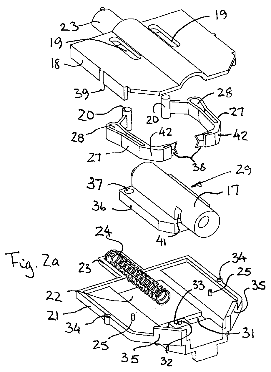
- Figure 2a shows the cassette 15 in exploded view in perspective, seen from above
- Figure 2b shows the cassette 15 in exploded view in perspective, seen from below.
- the cassette 15 comprises a base 21, a spring 24, a receiver body 17 for receiving and temporarily storing a sheath 30, arms 27, and a lid 18.
- the base 21 is provided with a recess 22, axially arranged with respect to the opening 16 and a semi-cylindrical, cradle shaped part 23.
- the cradle shaped part 23 is aligned with a corresponding semi-cylindrical cradle shaped part 23 on the lid 18, thus together forming a house for the spring 24.
- the base 21 is provided with at least two upwards extending guide pins 25. The function of said guide pins 25 will be described in further detail below in conjunction with Figures 5 and 6 .
- a transverse recess 31 is arranged in the axially extending recess 22 .
- a knob 32 provided with a pin 33, extending upwards from the knob 32.
- the knob 32 is movable in transverse direction with respect to the recess 22.
- the base 21 is provided with holes 34 for receiving corresponding pins or screws 39 on the lid 18.
- the base 21 is provided with upwards projecting, skewed walls 35, configured in such way that the skewed walls 35 are pointing towards each other in direction towards the opening 16.
- the movable receiver body 17 is in the form of a cylindrical, hollow part with an opening, configured to receive and store the sheath 30.
- the hole in the cylindrical part extends in axial direction of the body 17.
- the receiver body 17 is further provided with a lower sledge portion 36, configured to be slidably arranged for movement back and from in the recess 22, subjected to the effect of the spring force of the spring 24.
- the front end of the sledge portion 36 is given a skewed shape, corresponding to the skewed walls 35.
- the sledge 36 is provided with holes 37.
- the holes 37 are configured to receive pivot pins 20, arranged at the end of the arms 27.
- each arm 27 is at one end provided with a pivot pin 20. Said pivot pin 20 extends out from the arm 27 both upwards and downwards. Further, the opposite end of each arm 27 is provided with knife edge(s) 38, configured to create the required locking effect for locking a sheath 30 inserted into the receiver body 17. Further, each arm 27 is provided with a slot 28, configured to receive the corresponding pin 25 on the base 21. In general each arm is given a more or less U-shape, having skewed intermediate portions between the slotted part and the pivot pin 20 on the one end and between the slotted part and the knife(s) 38 on the other end. In order to ease relative movement of the arms 27 with respect to the pin 25, the end of the slot 28 adjacent the pivot pin 20 is wider than the remaining part of the slot 28.
- the top cover 18 is provided with two slots 19, configured to receive the upper end of the pivot pin 20, allowing the pivot pins 20 to slide back and from in the slots 19 when the receiver body 17 is moved axially back and from. Further, the top cover 18 is given a portion having a cylindrical dome shaped section, adapted to the shape of the upper end of the receiver body 17 and skewed end surfaces. Further, the top cover 18 is provided with downwards projecting pins 39 configured to be introduced into corresponding holes in the base 21 for locking the two parts 18,21 together.
- the sledge 36 is provided with a recess 39 in its bottom surface, configured to cooperate with the upwards projecting pin 33 on the knob 32, securing that the sledge 36 may be locked in either of two positions. These locking functions will be described below in conjunction with Figures 8 and 9 .
- Figure 3 shows schematically in perspective a partly exploded view of the unit 10 corresponding to the view shown in Figure 1 , where the shielding cover or lid 18 is removed.
- the cassette 15 is provided with a base 21, which may form an integral and monolithic part of the bottom tray 11.
- the base 21 may be fixed to the bottom tray 11 by means of gluing, screws, snapping, or the like.
- each arm 27 is pivotably arranged on the sledge 36, rotating around the pivot pins 20 at the end of each arm 17.
- Each pin or shaft 20 is pivotably arranged in the corresponding recess or hole 37 at one end of the sledge 36.
- each arm comprises at least one knife edge 38, configured to be forced into contact with the sheath when inserted into the receiver body 17 through slots 41 in said body 17, reaching the interior axial bore of the receiver body 17.
- the arms 27 further comprises elongate slots or recesses 28, into which the guide pins 25 are arranged, so that when the receiver body 17 and the sledge 36 is moved in axial direction, the arms 27 move with respect to the pins 25, thereby causing a sideways movement of the arms and consequently the knife edges, which projects into the slot 41, into or out of locking contact with respect to the inserted sheath 30.
- the base is provided with two skewed surfaces 35, projecting upwards from the base, sideways displaced with respect to the opening 16. Said skewed surfaces 35 is configured to cooperate with corresponding skewed surfaces 42 on the arms 27, contributing to and enhancing the locking effect of the knife edges 38 on to the inserted sheath 30. Since the arm 27 is pivotably hinged at one end, and due to the slots or recesses 28 in the sideways projecting middle part of arms 27, an axial movement of the receiver body 17 with the sledge body 36 will cause a motion of the opposite end of the arm 27 out of or into the slot 41, producing or suspending the locking effect on the sheath 30.
- the grooves 28 are configured to cooperate with the pins 25 so as to function as a guide for the axial displacement of the moveable part 29 of the locking and retaining cassette 15.
- the receiver body 17 is configured to move back and from in the recess 22, the arms 27 moving together with the receiver body 17. Such movement is guided by the pivot pins 20, sliding back and from in the slots 19 in the top cover 18 of the unit 10.
- the axial movement of the receiver body 17 also causes the arms 27 to pivot around the pivot 20, such pivoting movement being caused by the stationary guide pins 25 sliding in the slots 28 in the arms 27, moving the edges 38 out of or into the slots 41 in the receiver body. In such way, a locking or releasing effect of the sheath 30 is provided.
- tubular body 17 is configured for receiving a sheath 30 and locking and retaining such sheath 30 when the syringe is administered.
- the tubular body 17 is provided with an axially arranged, tubular hole and a tapered mouth, the dimensions of such recess being chosen so that the unit 10 may be used for most of the commercially available syringes with sheaths 30, independent of supplier.
- the tubular body is provided with an axially arranged tubular recess, intended to receive one end of the spring 24, securing proper attachment of such spring 24 to the receiver body 17.
- Figure 4 shows schematically in perspective the lower part of the unit shown in Figure 1 , where a sheath 30 is inserted into the receiver body 17 and where sheath 30 is in locked position, the receiver body 17 being in its outer extreme position, locking the sheath and storing it temporarily, until the needle of the syringe is reintroduced into the sheath 30 and the locking effect of the locking mechanism again being released by a slight movement of the receiver body 17, thus enabling the operator to remove a sheathed syringe out of the unit 10.
- Figure 5 and 6 show schematically in perspective two extreme positions of the locking and retaining receiver body 15 with the cover 18 removed.
- Figure 5 shows a position where the free ends of the pivotable arms 27 are in a locking position
- Figure 6 show the opposite position where the holding and locking effects of the arms 27 are suspended.
- the skewed surfaces 35 on the base 21 and the skewed surfaces 42 on the arms contribute to the forcing of the knife edges 38 of the arms 27 into the slot 41 in the receiver body 17.
- FIG. 7 shows the bottom element 21 of the cassette 15, seen from above.
- the bottom element 21 has a recess 22, configured to receive the movable sledge 29 of the receiver body 17.
- the recess 22 extends in one axial direction, coinciding with the cradle shaped body 23 at the rear end of the bottom element 21.
- a knob 32 provided with an upwards projecting pin 33 is arranged in a second recess 31 which extends in traverse direction with respect to the recess 22, the knob 32 being configured to move back and from in the recess 31.
- Said pin 33 is configured to be in engagement with a recess 39 in the lower surface of the movable sledge 36 on the receiver body 17.
- Figure 8 shows the receiver body 17 and the cover 18 seen from below, showing the recesses 19 for guiding the pivots 20, the shape of the recess 39 on the bottom surface of the sledge 36, parts of the arms 27.
- the receiver body 17 is in a position where the knife edges 38 on the arms 27 are in the first position, not inserted into the slots 41 and into a central bore in the receiver body 17.
- the pins or shafts 25 are in the narrow part of the slot 28. In this position substantially no or little spring force acts on the sledge 36.
- Figure 9 shows a view of receiver body 17 seen from below, indicating the various surfaces and seats referred to below.
- the lower surface of the sledge 36 of the receiver body 17 is provided with a recess 39 being provided a centrally arranged middle part 47 projecting outwards from the recess 39, creating guiding surfaces and recesses.
- the surface of the sledge 36 of the receiver body 17 and the outer surface of the centrally arranged middle part 47 co-inside.
- each of the Figures 10-21 show a view seen from above of the cassette 15 with the cover 18 removed.
- Each Figure shows the positions of the arms 27 and the locking knife edges 38 during the various stages.
- each Figure shows an enlarged view of the part of the unit marked with a circle, showing the various positions of the pin 33 on the knob 32 with respect to the various seats and surfaces of the recess 39.
- Figure 10 shows a position where the receiver body 17 is in an open position, ready for receiving the sheath 30.
- the locking knife edges 38 are in its extreme outer position, allowing introduction of the sheath 30 into the central hole in the receiver body 17.
- the pin 33 on the movable knob 32 is resting in its extreme outer locking seat 43 in the recess 39.
- the guide pins 25 are in a middle position in the slots 28 in the arms 27.
- the spring 24 is in a compressed position, exerting a spring force on the receiver body 17, thus locking the position of the receiver body 17.
- the user presses a sheath 30 into the receiver body 17, moving the receiver body 17 inwards so that the pin 33 leaves its seat 43 while the receiver body 17 and the arms 27 are pressed even further into the cassette 15, thereby forcing the knife edges 38 further out of the slot 41, securing free access for the sheath 30 into the receiver body 17.
- the pin 33 hits a skewed surface 44, thus moving the knob 32 sideways towards left on Figure 11 .
- Figure 12 shows a view where the pin 33 on the movable knob 32 is in its extreme, intermediate position, resting against the extreme intermediate seat 45, in which the pin 33 is free off the edge 46 on the central part 47 of the recess 39.
- the guide pins 25 are in their extreme end position in the slots 28 in the arms 27.
- the receiver body 17 During the movement between the position shown in Figure 15 and the position shown in Figure 16 , the receiver body 17 has moved towards the front end, the skewed surfaces 42 on the arms 27 contacting the skewed walls 35, so that the arms 27 are forced into the slots 41 in the receiver body 17, forcing the knife edges 38 into locking contact with the sheath 30.
- the receiver body 17 will remain in this extreme end position, exposed by the counteracting spring force, until the user again manipulates the sheath 30 by inserting the needle into the locked sheath, pressing the receiver body 17 inwards against the action of spring force of the spring 24.
- Figure 21 corresponds to figure 10 .
- the sheath 30 is free to be removed, attached on the needle, while the cassette 15 is ready for receiving a new sheath 30.
- a solution being safe and simple to handle is provided, reducing the risk of being pricked when sheathing or unsheathing a needle on a syringe.
- a unit enabling one-hand unsheathing or re-sheathing for example a sheath of plastic materials of a syringe needle is provided, enabling operation without having to touch the sheath and/or the unit.
- the unit is easy to use and is reliable in use. Further, it will be possible to handle the unit by only using use one hand when sheathing and/or unsheathing a needle on a syringe.
- the unit is purely mechanical, not requiring other energy sources than the force provided by the user, inserting or removing the sheathed or un-sheathed syringe needle into or out of the unit.
- the unit which is maintenance free and does not require special cleaning as a consequence of normal use, since no direct contact bye the user is necessary.
Abstract
The present invention relates to a unit (10) for safe handling of needles of syringes, including unsheathing and/or re-sheathing a sheath (30) covering the syringe needle, the unit (10) comprises retaining means (15) for locking, temporarily storing and releasing the stored sheath (30), and means for manipulating said retaining means (15) to provide and/or suspend the locking effect on the sheath (30).
Said means (15) for locking, temporarily storing and releasing the stored sheath (30) comprises a receiver body (17), movable in a first direction with respect to a housing (18,21) against a force of a spring (24), and at least one locking surface (38), movable in a second direction with respect to the direction of movement of the receiving body (17), moving the locking surfaces (38) into or out of engagement with the inserted sheath (30), such latter movement being caused by the movement of the receiving body (17).
Description
- The present invention relates to a unit for safe handling of syringe needles, including unsheathing and/or re-sheathing a sheath covering the syringe needle, the unit comprises retaining means for locking, temporarily storing and releasing the stored sheath, and means for manipulating said retaining means to provide and/or suspend the locking effect on the sheath.
- A syringe, for example for medical use, is used for injection a solution or a liquid into or withdrawing blood or body fluids from a body. From a safety point of view it is important that the user, and/or the patient on which medication or liquid withdrawal is administered, is not accidentally pricked by the needle of the syringe. It is also imperative that the needle remains sterile prior to insertion into the human body.
- The conventional syringes has a tubular sheath placed on the syringe needle, securing that the needle remains sterile and preventing accidental pricking. Such sheath must be removed prior to insertion, requiring normally two hands for unsheathing or re-sheathing.
- Hence, there is a need for equipment enabling removal of a sheath with one hand. It has previously been proposed to use an apparatus permitting a person to unsheathe and re-sheath the needle with the use of only one hand.
-
US 5,242,426 describes an apparatus for permitting a person to unsheath and re-sheath the needles of hypodermic syringes, catheters, etc., with the use of only one hand. The apparatus permits free use of the individual's other hand when such is required, e.g. when restraint of the patient is necessary in order to properly and safely administer an injection from a hypodermic needle or the like. The apparatus securely holds and positions a medical needle sheath during such times that a medical needle is removed from and re-inserted into the sheath. -
US 5,067,949 describes a means for protecting the user of a medical syringe from being pricked by its needle when unsheathing or re-sheathing the needle. The means has an upper member mounted atop a disposable container. A vertical passage through the upper member empties through a hole into the container. The passage has a coned entry mouth enabling the user to guide the sheathed needle end of a syringe into the passage. A cam in the upper member is pivotably arranged to hold the sheathed needle in the passage, so that the user may pull the on the syringe and separate its needle end from the sheath, or later, the user may re-insert the used needle end of the syringe into the cammed sheath and, upon twisting the syringe, separate it from the needle to allow the separated re-sheathed needle to drop into the container following release of the cammed condition. -
US 5,308,582 describes a hypodermic syringe uncapping device which includes a housing enclosing two opposed, pivotal arms adapted to grip a cap protecting a hypodermic syringe needle. Upon insertion through a hole in the housing, the capped needle is forced against a movable plunger whose lower end engages one of a number of pins extending from the surface of a rotatable cam located between the arms. Rotation of the cam thus induced allows the arms to pivot towards each other under the urging of an arm-connecting spring, causing the arms to grasp the cap and thereby allow subsequent withdrawal of the needle. When the needle is re-inserted in the cap and the cap is again pushed against the plunger, the cam is rotated still further, forcing the arms apart and permitting the cap to be withdrawn from the device. - There is a need for an improved apparatus which is safe to use, eliminating the risk for being pricked by the needle, such apparatus also being reliable and simple in construction, easy to operate, and providing improved locking effect on the sheath. Further there is a need for an apparatus which does not occupy a large space or which may be handheld.
- An object of the present invention is to provide a solution which is safe and simple to handle, reducing the risk of being pricked when sheathing or unsheathing a needle on a syringe.
- A further object of the invention is to provide a unit enabling one-hand unsheathing or re-sheathing, for example a sheath of plastic materials of a syringe needle, without having to touch the sheath and/or the unit.
- Another object of the present invention is to provide a unit which is easy to use and being reliable in use.
- A still further object of the present invention is to provide a unit making the possible only to use one hand when sheathing and/or unsheathing a needle on a syringe.
- Yet another object is to provide a unit which is purely mechanical, not requiring other energy sources than the force provided by the user, inserting or removing the sheathed or un-sheathed syringe needle into or out of the unit.
- A still further object of the present invention is to provide a unit which is maintenance free.
- A still further object is to provide a unit not requiring special cleaning as a consequence of normal use, since no direct contact bye the user is necessary.
- According to the present invention, said objects are achieved by a unit as further defined by the independent claim. Different embodiments of the unit according to the invention are defined in the dependent claims.
- According to one embodiment of the invention, the means for locking, temporarily storing and releasing the stored sheath comprises a receiver body, movable in a first direction with respect to a housing against a force of a spring, and at least one locking surface, movable in a second direction with respect to the direction of movement of the receiving body, moving the locking surfaces into or out of engagement with the inserted sheath, such latter movement being caused by the movement of the receiving body.
- According to one embodiment, said movement of the receiver body may be linear, while the movement of said at least one locking surface preferably may be perpendicularly towards the sheath.
- Said at least one locking edge or surface may extend through an opening or slot in the wall of the receiver body, providing a lateral retaining forced on the sheath, thereby locking sheath against axial movement.
- At least two locking surfaces, diametrically arranged with respect to the receiver body, may be used.
- Further, the locking surfaces of the locking means may be configured in such way that at least four contact points against the sheath are formed. Preferably, the locking means may be in the form of knife edged surface.
- Each locking surface may be attached to an arm, said arm being pivotably arranged in such way that the free end of each arm is forced laterally towards and into the tubular body by means of a skewed contact walls arranged in the housing, causing a wedging effect so that the locking effects of the knives are further enhanced when the syringed is pulled outwards.
- According to another embodiment, a surface on the receiver body may be provided with groove or recess while a corresponding surface of a knob of the housing is provided with a pin arranged on a knob movably arranged in said groove, the groove being configured in such way the locking effect of the receiver body may be suspended by pushing the receiver body inwards against the action of the spring force and then release the inwards pressure.
- The unit may preferably, but not necessary, be fixed inside a housing configured to be attached to a supporting surface, the unit forming an integral part of the housing.
- One embodiment of the present invention will be described below referring to the accompanying drawings, wherein:
-
Figure 1 shows schematically in perspective a partly exploded view of a unit for secure handling of syringes; -
Figure 2a shows the cassette in exploded view in perspective, seen from above, whileFigure 2b shows the cassette in exploded view in perspective, seen from below; -
Figure 3 shows schematically in perspective a partly exploded view corresponding to the view shown inFigure 1 , where a shielding cover is removed; -
Figure 4 shows schematically in perspective the lower part of the unit shown inFigure 1 , where a syringe is inserted into to receptacle; -
Figure 5 and 6 show schematically in perspective two extreme positions of the locking and retaining element with the cover removed, whereFigure 5 shows a position where the ends of the pivotable arms in a locking apposition, whileFigure 6 show the opposite position where the holding effects of the arms are suspended; -
Figure 7 shows the bottom element of the cassette according to the present invention; -
Figure 8 shows the top element of the cassette with the locking element and the arms, seen from below; -
Figure 9 shows a view of thereceiver body 17, seen from above; and -
Figures 10-21 show various stages in the manipulating process of the receiver body for securing locking and/or release of the sheath in the receiver body. -
Figure 1 shows schematically in perspective a partly exploded view of aunit 10 for secure handling of syringes (not shown). Theunit 10 comprises abottom tray 11 and atop cover 12, configured to be assembled to a single body, e.g. by means of screws, snapping elements or the like. Thebottom tray 11 may be provided with reinforcedareas 13 provided withholes 14 for enabling fixing of theunit 10 to a supporting surface (not shown) by means e.g. of screws (not shown) or the like. - When assembled, the
bottom tray 11 and thetop cover 12 form a hollow body containing a closed locking and retainingcassette 15 which will be described in further detail below. Further one side wall in thebottom part 11 and the corresponding side wall of thetop part 12 are provided with recesses, forming anopening 16 when assembled, the opening 16 being configured for receiving one end of an axially displaceable, outwardly protrudingtubular receiver body 17 of thecassette 15. As will be described in further detail below, thecassette 15 is fixed to thebottom part 11, e.g. by means of screws, glue, snapping means or the like. Thecassette 15 comprises in principle abase 21, a movable sledge orbody 29, pivotably arrangedarms 27, aspring 24 and acover 18. Thecassette 15 as such and the functioning of thecassette 15 will be described in further details below. -
Figure 2a shows thecassette 15 in exploded view in perspective, seen from above, whileFigure 2b shows thecassette 15 in exploded view in perspective, seen from below. As indicated the inFigures 2a and 2b , thecassette 15 comprises abase 21, aspring 24, areceiver body 17 for receiving and temporarily storing asheath 30,arms 27, and alid 18. - The
base 21 is provided with arecess 22, axially arranged with respect to theopening 16 and a semi-cylindrical, cradle shapedpart 23. The cradle shapedpart 23 is aligned with a corresponding semi-cylindrical cradle shapedpart 23 on thelid 18, thus together forming a house for thespring 24. Further, thebase 21 is provided with at least two upwards extending guide pins 25. The function of said guide pins 25 will be described in further detail below in conjunction withFigures 5 and 6 . Further, in theaxially extending recess 22, atransverse recess 31 is arranged. Aknob 32, provided with apin 33, extending upwards from theknob 32. Theknob 32 is movable in transverse direction with respect to therecess 22. Further, thebase 21 is provided withholes 34 for receiving corresponding pins or screws 39 on thelid 18. - At the front end of the
recess 22, i.e. the end adjacent theopening 16 of theunit 10, thebase 21 is provided with upwards projecting, skewedwalls 35, configured in such way that the skewedwalls 35 are pointing towards each other in direction towards theopening 16. - The
movable receiver body 17 is in the form of a cylindrical, hollow part with an opening, configured to receive and store thesheath 30. The hole in the cylindrical part extends in axial direction of thebody 17. Thereceiver body 17 is further provided with alower sledge portion 36, configured to be slidably arranged for movement back and from in therecess 22, subjected to the effect of the spring force of thespring 24. The front end of thesledge portion 36 is given a skewed shape, corresponding to the skewedwalls 35. At the opposite end of thesledge 36, thesledge 36 is provided withholes 37. Theholes 37 are configured to receive pivot pins 20, arranged at the end of thearms 27. - As specified above, the
arms 27 are at one end provided with apivot pin 20. Saidpivot pin 20 extends out from thearm 27 both upwards and downwards. Further, the opposite end of eacharm 27 is provided with knife edge(s) 38, configured to create the required locking effect for locking asheath 30 inserted into thereceiver body 17. Further, eacharm 27 is provided with aslot 28, configured to receive thecorresponding pin 25 on thebase 21. In general each arm is given a more or less U-shape, having skewed intermediate portions between the slotted part and thepivot pin 20 on the one end and between the slotted part and the knife(s) 38 on the other end. In order to ease relative movement of thearms 27 with respect to thepin 25, the end of theslot 28 adjacent thepivot pin 20 is wider than the remaining part of theslot 28. - The
top cover 18 is provided with twoslots 19, configured to receive the upper end of thepivot pin 20, allowing the pivot pins 20 to slide back and from in theslots 19 when thereceiver body 17 is moved axially back and from. Further, thetop cover 18 is given a portion having a cylindrical dome shaped section, adapted to the shape of the upper end of thereceiver body 17 and skewed end surfaces. Further, thetop cover 18 is provided with downwards projectingpins 39 configured to be introduced into corresponding holes in thebase 21 for locking the twoparts - As shown in
Figure 2b , thesledge 36 is provided with arecess 39 in its bottom surface, configured to cooperate with theupwards projecting pin 33 on theknob 32, securing that thesledge 36 may be locked in either of two positions. These locking functions will be described below in conjunction withFigures 8 and9 . -
Figure 3 shows schematically in perspective a partly exploded view of theunit 10 corresponding to the view shown inFigure 1 , where the shielding cover orlid 18 is removed. As shown inFigure 3 , thecassette 15 is provided with abase 21, which may form an integral and monolithic part of thebottom tray 11. Alternatively, thebase 21 may be fixed to thebottom tray 11 by means of gluing, screws, snapping, or the like. - According to the embodiment shown in
Figure 3 , the twoarms 27 are pivotably arranged on thesledge 36, rotating around the pivot pins 20 at the end of eacharm 17. Each pin orshaft 20 is pivotably arranged in the corresponding recess orhole 37 at one end of thesledge 36. Further, as indicated above, each arm comprises at least oneknife edge 38, configured to be forced into contact with the sheath when inserted into thereceiver body 17 throughslots 41 in saidbody 17, reaching the interior axial bore of thereceiver body 17. Thearms 27 further comprises elongate slots or recesses 28, into which the guide pins 25 are arranged, so that when thereceiver body 17 and thesledge 36 is moved in axial direction, thearms 27 move with respect to thepins 25, thereby causing a sideways movement of the arms and consequently the knife edges, which projects into theslot 41, into or out of locking contact with respect to the insertedsheath 30. - At the end of the base 21 facing the
opening 16, the base is provided with twoskewed surfaces 35, projecting upwards from the base, sideways displaced with respect to theopening 16. Said skewedsurfaces 35 is configured to cooperate with correspondingskewed surfaces 42 on thearms 27, contributing to and enhancing the locking effect of the knife edges 38 on to the insertedsheath 30. Since thearm 27 is pivotably hinged at one end, and due to the slots or recesses 28 in the sideways projecting middle part ofarms 27, an axial movement of thereceiver body 17 with thesledge body 36 will cause a motion of the opposite end of thearm 27 out of or into theslot 41, producing or suspending the locking effect on thesheath 30. Thegrooves 28 are configured to cooperate with thepins 25 so as to function as a guide for the axial displacement of themoveable part 29 of the locking and retainingcassette 15. The design, configuration and the function of the various elements of the retaining and lockingcassette 15 will be described in further detail below. - As further indicated in
Figure 3 , thereceiver body 17 is configured to move back and from in therecess 22, thearms 27 moving together with thereceiver body 17. Such movement is guided by the pivot pins 20, sliding back and from in theslots 19 in thetop cover 18 of theunit 10. The axial movement of thereceiver body 17 also causes thearms 27 to pivot around thepivot 20, such pivoting movement being caused by the stationary guide pins 25 sliding in theslots 28 in thearms 27, moving theedges 38 out of or into theslots 41 in the receiver body. In such way, a locking or releasing effect of thesheath 30 is provided. - One end of the
tubular body 17 is configured for receiving asheath 30 and locking and retainingsuch sheath 30 when the syringe is administered. For such purpose thetubular body 17 is provided with an axially arranged, tubular hole and a tapered mouth, the dimensions of such recess being chosen so that theunit 10 may be used for most of the commercially available syringes withsheaths 30, independent of supplier. - At the opposite end, the tubular body is provided with an axially arranged tubular recess, intended to receive one end of the
spring 24, securing proper attachment ofsuch spring 24 to thereceiver body 17. -
Figure 4 shows schematically in perspective the lower part of the unit shown inFigure 1 , where asheath 30 is inserted into thereceiver body 17 and wheresheath 30 is in locked position, thereceiver body 17 being in its outer extreme position, locking the sheath and storing it temporarily, until the needle of the syringe is reintroduced into thesheath 30 and the locking effect of the locking mechanism again being released by a slight movement of thereceiver body 17, thus enabling the operator to remove a sheathed syringe out of theunit 10. -
Figure 5 and 6 show schematically in perspective two extreme positions of the locking and retainingreceiver body 15 with thecover 18 removed.Figure 5 shows a position where the free ends of thepivotable arms 27 are in a locking position, whileFigure 6 show the opposite position where the holding and locking effects of thearms 27 are suspended. As seen in theFigure 5 the skewed surfaces 35 on thebase 21 and the skewed surfaces 42 on the arms contribute to the forcing of the knife edges 38 of thearms 27 into theslot 41 in thereceiver body 17. -
Figure 7 shows thebottom element 21 of thecassette 15, seen from above. As shown, thebottom element 21 has arecess 22, configured to receive themovable sledge 29 of thereceiver body 17. Therecess 22 extends in one axial direction, coinciding with the cradle shapedbody 23 at the rear end of thebottom element 21. As shown aknob 32 provided with anupwards projecting pin 33 is arranged in asecond recess 31 which extends in traverse direction with respect to therecess 22, theknob 32 being configured to move back and from in therecess 31. Saidpin 33 is configured to be in engagement with arecess 39 in the lower surface of themovable sledge 36 on thereceiver body 17. -
Figure 8 shows thereceiver body 17 and thecover 18 seen from below, showing therecesses 19 for guiding thepivots 20, the shape of therecess 39 on the bottom surface of thesledge 36, parts of thearms 27. As shown, thereceiver body 17 is in a position where the knife edges 38 on thearms 27 are in the first position, not inserted into theslots 41 and into a central bore in thereceiver body 17. The pins orshafts 25 are in the narrow part of theslot 28. In this position substantially no or little spring force acts on thesledge 36. -
Figure 9 shows a view ofreceiver body 17 seen from below, indicating the various surfaces and seats referred to below. In general, the lower surface of thesledge 36 of thereceiver body 17 is provided with arecess 39 being provided a centrally arrangedmiddle part 47 projecting outwards from therecess 39, creating guiding surfaces and recesses. The surface of thesledge 36 of thereceiver body 17 and the outer surface of the centrally arrangedmiddle part 47 co-inside. - In the following the function of the
unit 10 will be described in further details, referring toFigures 9-21 . - Each of the
Figures 10-21 show a view seen from above of thecassette 15 with thecover 18 removed. Each Figure shows the positions of thearms 27 and the locking knife edges 38 during the various stages. Further, each Figure shows an enlarged view of the part of the unit marked with a circle, showing the various positions of thepin 33 on theknob 32 with respect to the various seats and surfaces of therecess 39. -
Figure 10 shows a position where thereceiver body 17 is in an open position, ready for receiving thesheath 30. As indicated inFigure 10 , the locking knife edges 38 are in its extreme outer position, allowing introduction of thesheath 30 into the central hole in thereceiver body 17. In this position, thepin 33 on themovable knob 32 is resting in its extremeouter locking seat 43 in therecess 39. Further, in this position, the guide pins 25 are in a middle position in theslots 28 in thearms 27. Thespring 24 is in a compressed position, exerting a spring force on thereceiver body 17, thus locking the position of thereceiver body 17. - According to
Figure 11 the user presses asheath 30 into thereceiver body 17, moving thereceiver body 17 inwards so that thepin 33 leaves itsseat 43 while thereceiver body 17 and thearms 27 are pressed even further into thecassette 15, thereby forcing the knife edges 38 further out of theslot 41, securing free access for thesheath 30 into thereceiver body 17. As indicated in the enlarged part of the Figure, thepin 33 hits a skewed surface 44, thus moving theknob 32 sideways towards left onFigure 11 . -
Figure 12 shows a view where thepin 33 on themovable knob 32 is in its extreme, intermediate position, resting against the extremeintermediate seat 45, in which thepin 33 is free off the edge 46 on thecentral part 47 of therecess 39. As further indicated in theFigure 12 , the guide pins 25 are in their extreme end position in theslots 28 in thearms 27. - Upon release of the inwards pressure the spring will, as shown in
Figure 13 , force thereceiver body 17 outwards, securing that thepin 33 on theknob 32 will hit the outer skewedsurface 55 on the outwards projectingmiddle part 47, passing the centrally arranged outwards projectingmiddle part 47 in therecess 39, ref.Figure 13 . When the pressure on thereceiver body 17 is further released, thepin 33 will as indicated inFigure 14 , slide along thesurface 48. As shown inFigure 15 , the pin will then hit the skewed surface 49 and enter into the oppositeextreme seat 50, ref.Figure 16 . During the movement between the position shown inFigure 15 and the position shown inFigure 16 , thereceiver body 17 has moved towards the front end, the skewed surfaces 42 on thearms 27 contacting the skewedwalls 35, so that thearms 27 are forced into theslots 41 in thereceiver body 17, forcing the knife edges 38 into locking contact with thesheath 30. Thereceiver body 17 will remain in this extreme end position, exposed by the counteracting spring force, until the user again manipulates thesheath 30 by inserting the needle into the locked sheath, pressing thereceiver body 17 inwards against the action of spring force of thespring 24. Such movement will, due to the guide pins 25 in theslots 28 in thearms 27, and due to the pressure induced on thereceiver body 17 by the user, retract the knife edges 38 from its locking position in theslot 41. Thepin 33 on theknob 32 will then hit the skewedsurface 51 on the central, outwards projectingbody 47 in therecess 39, ref.Figure 17 , allowing thepin 33 to slide along thissurface 51, until the pin passes thetip surface 52, ref.Figure 18 , whereupon thepin 33 will move further down into a second,temporary seat 53, ref.Figure 19 . During such movement, thepin 33 and theknob 32 have been moved slightly inwards (to the left on the Figure when it hits the skewedwall 56. Thereupon, thepin 33 will move in opposite direction from the secondtemporary seat 53, hitting the skewed surface 54, ref.Figure 20 and sliding back into the first lockingseat 43, ref.Figure 21 . For the sake of good order,Figure 21 corresponds tofigure 10 . At this stage thesheath 30 is free to be removed, attached on the needle, while thecassette 15 is ready for receiving anew sheath 30. - According to the present invention a solution being safe and simple to handle is provided, reducing the risk of being pricked when sheathing or unsheathing a needle on a syringe.
- Further a unit enabling one-hand unsheathing or re-sheathing, for example a sheath of plastic materials of a syringe needle is provided, enabling operation without having to touch the sheath and/or the unit.
- It should also be appreciated that the unit is easy to use and is reliable in use. Further, it will be possible to handle the unit by only using use one hand when sheathing and/or unsheathing a needle on a syringe.
- Also, the unit is purely mechanical, not requiring other energy sources than the force provided by the user, inserting or removing the sheathed or un-sheathed syringe needle into or out of the unit.
- Further, the unit which is maintenance free and does not require special cleaning as a consequence of normal use, since no direct contact bye the user is necessary.
Claims (10)
- Unit (10) for safe handling of needles of syringes, including unsheathing and/or re-sheathing a sheath (30) covering the syringe needle, the unit (10) comprises retaining means (15) for locking, temporarily storing and releasing the stored sheath (30), and means for manipulating said retaining means (15) to provide and/or suspend the locking effect on the sheath (30),
characterized in that said means (15) for locking, temporarily storing and releasing the stored sheath (30) comprises a receiver body (17), movable in a first direction with respect to a housing (18,21) against a force of a spring (24), and at least one locking surface (38), movable in a second direction with respect to the direction of movement of the receiving body (17), moving the locking surfaces (38) into or out of engagement with the inserted sheath (30), such latter movement being caused by the movement of the receiving body (17). - Unit (10) according to claim 1, wherein said movement of the receiver body (17) is linear.
- Unit (10) according to claim 1 or 2, wherein the movement of said at least one locking surface (38) is perpendicularly towards the sheath (30).
- Unit (10) according to one of the claims 1-3, wherein said at least one locking edge or surface (38) extends through an opening (41) in the wall of the receiver body (17), providing a lateral retaining forced on the sheath (30), thereby locking sheath (30) against axial movement.
- Unit (10) according to one of the claims 1-4, wherein at least two locking surfaces (38) are diametrically arranged with respect to the receiver body (17).
- Unit (10) according to one of the claims 1-5, wherein the locking surfaces (38) of the locking means are configured in such way that at least four contact points against the sheath (30) are formed.
- Unit (10) according to one of the claims 1-6, wherein the locking means are in the form of knife edged surface (38).
- Unit (10) according to one of the claims 1-7, wherein each locking surface (38) is attached to an arm (27), said arm (27) being pivotably arranged in such way that the free end of each arm (27) is forced laterally towards the tubular body (17) by means of a skewed contact walls (35) arranged in the housing (18,21), causing a wedging effect so that the locking effects of the knives (38) are further enhanced when the syringed is pulled outwards.
- Unit (10) to one of the claims 1-8, wherein a surface on the receiver body (17) is provided with groove or recess (39) while a corresponding surface of a knob (32) of the housing (18,21) being provided with a pin (33) arranged on a knob (32) movably arranged in said groove (39), the groove (39) being configured in such way the locking effect of the receiver body (17) may be suspended by pushing the receiver body (17) inwards against the action of the spring force and then release the inwards pressure.
- Unit (10) according to one of the claims 1-9, wherein the unit (10) is fixed inside a housing (11,12) configured to be attached to a supporting surface, the unit (10) forming an integral part of the housing (11,12).
Priority Applications (1)
| Application Number | Priority Date | Filing Date | Title |
|---|---|---|---|
| EP09170149A EP2295099A1 (en) | 2009-09-14 | 2009-09-14 | Unit for safe unsheathing and re-sheathing of syringe needles |
Applications Claiming Priority (1)
| Application Number | Priority Date | Filing Date | Title |
|---|---|---|---|
| EP09170149A EP2295099A1 (en) | 2009-09-14 | 2009-09-14 | Unit for safe unsheathing and re-sheathing of syringe needles |
Publications (1)
| Publication Number | Publication Date |
|---|---|
| EP2295099A1 true EP2295099A1 (en) | 2011-03-16 |
Family
ID=41683449
Family Applications (1)
| Application Number | Title | Priority Date | Filing Date |
|---|---|---|---|
| EP09170149A Withdrawn EP2295099A1 (en) | 2009-09-14 | 2009-09-14 | Unit for safe unsheathing and re-sheathing of syringe needles |
Country Status (1)
| Country | Link |
|---|---|
| EP (1) | EP2295099A1 (en) |
Cited By (4)
| Publication number | Priority date | Publication date | Assignee | Title |
|---|---|---|---|---|
| FR3025433A1 (en) * | 2014-09-09 | 2016-03-11 | Nemera La Verpilliere | DEVICE FOR REMOVING A PROTECTIVE CAP FROM A SYRINGE NEEDLE |
| WO2017016984A1 (en) * | 2015-07-24 | 2017-02-02 | Vetter Pharma-Fertigung GmbH & Co. KG | Removal device for a needle protection cap, and method |
| US10722659B2 (en) | 2015-03-31 | 2020-07-28 | Southern Innovationz Limited | Apparatus for unsheathing and resheathing a needle device |
| GB2536412B (en) * | 2015-03-09 | 2021-04-21 | Diabetes Care Tech Ltd | A casing |
Citations (6)
| Publication number | Priority date | Publication date | Assignee | Title |
|---|---|---|---|---|
| US5067949A (en) | 1990-04-23 | 1991-11-26 | Freundlich Lawrence F | Instrument for unsheathing, resheathing and disposing of a medical syringe needle |
| US5242426A (en) | 1989-09-18 | 1993-09-07 | Pituch Daniel W | Medical needle sheath holding apparatus |
| US5308582A (en) | 1993-02-11 | 1994-05-03 | Serra Louis M | Syringe capping and uncapping device |
| DE202004010129U1 (en) * | 2004-06-29 | 2004-08-26 | Dieter Hölzle Technik-Projekte GmbH | Device for removal and insertion of the protective cap, in particular, of a syringe held in an automatic injection unit comprises a clamping collet activatable by a motion against the force a releasable spring |
| US20070173772A1 (en) * | 2004-02-14 | 2007-07-26 | Liversidge Barry P | Medical injector handling device |
| WO2009087355A1 (en) * | 2008-01-04 | 2009-07-16 | Owen Mumford Limited | Sheath remover device |
-
2009
- 2009-09-14 EP EP09170149A patent/EP2295099A1/en not_active Withdrawn
Patent Citations (6)
| Publication number | Priority date | Publication date | Assignee | Title |
|---|---|---|---|---|
| US5242426A (en) | 1989-09-18 | 1993-09-07 | Pituch Daniel W | Medical needle sheath holding apparatus |
| US5067949A (en) | 1990-04-23 | 1991-11-26 | Freundlich Lawrence F | Instrument for unsheathing, resheathing and disposing of a medical syringe needle |
| US5308582A (en) | 1993-02-11 | 1994-05-03 | Serra Louis M | Syringe capping and uncapping device |
| US20070173772A1 (en) * | 2004-02-14 | 2007-07-26 | Liversidge Barry P | Medical injector handling device |
| DE202004010129U1 (en) * | 2004-06-29 | 2004-08-26 | Dieter Hölzle Technik-Projekte GmbH | Device for removal and insertion of the protective cap, in particular, of a syringe held in an automatic injection unit comprises a clamping collet activatable by a motion against the force a releasable spring |
| WO2009087355A1 (en) * | 2008-01-04 | 2009-07-16 | Owen Mumford Limited | Sheath remover device |
Cited By (4)
| Publication number | Priority date | Publication date | Assignee | Title |
|---|---|---|---|---|
| FR3025433A1 (en) * | 2014-09-09 | 2016-03-11 | Nemera La Verpilliere | DEVICE FOR REMOVING A PROTECTIVE CAP FROM A SYRINGE NEEDLE |
| GB2536412B (en) * | 2015-03-09 | 2021-04-21 | Diabetes Care Tech Ltd | A casing |
| US10722659B2 (en) | 2015-03-31 | 2020-07-28 | Southern Innovationz Limited | Apparatus for unsheathing and resheathing a needle device |
| WO2017016984A1 (en) * | 2015-07-24 | 2017-02-02 | Vetter Pharma-Fertigung GmbH & Co. KG | Removal device for a needle protection cap, and method |
Similar Documents
| Publication | Publication Date | Title |
|---|---|---|
| US3880163A (en) | Medicinal syringe actuating device | |
| CA2405978C (en) | Storage container for at least one hypodermic needle | |
| EP2506897B1 (en) | Pen needle removal device for a drug delivery device | |
| AU2007249578C1 (en) | Blood collection device with needle container means | |
| US11564604B2 (en) | Passive double drive member activated safety blood collection device | |
| CA1270716A (en) | Device for removing needles or needle/sheath combination from hypodermic syringes | |
| EP0343803A2 (en) | Safety introduction means for catheter | |
| KR20150097784A (en) | Medicament delivery device | |
| KR20160148066A (en) | Palm activated drug delivery device | |
| WO1999006302A1 (en) | A dental sharps containment device and method of using the same | |
| EP2295099A1 (en) | Unit for safe unsheathing and re-sheathing of syringe needles | |
| US20210170092A1 (en) | Pen needle assembly apparatus | |
| EP3895748A2 (en) | Safe injector needle | |
| WO1991008786A1 (en) | Hypodermic needle sheath | |
| DK2632513T3 (en) | SAFETY DEVICES | |
| WO2000025845A1 (en) | Needle assembly | |
| JP7266605B2 (en) | pen needle assembly instrument | |
| CN209900309U (en) | Pen type needle assembly device | |
| CN108144159B (en) | Device for mounting a pen needle assembly | |
| CN109966596B (en) | Pen needle assembling equipment | |
| CA1278729C (en) | Device for supporting and dispensing an instrument | |
| JP7246397B2 (en) | Pen needle assembly device | |
| CN110384841B (en) | Pen type needle assembly device | |
| CN117339059A (en) | Automatic injection device for a syringe |
Legal Events
| Date | Code | Title | Description |
|---|---|---|---|
| PUAI | Public reference made under article 153(3) epc to a published international application that has entered the european phase |
Free format text: ORIGINAL CODE: 0009012 |
|
| AK | Designated contracting states |
Kind code of ref document: A1 Designated state(s): AT BE BG CH CY CZ DE DK EE ES FI FR GB GR HR HU IE IS IT LI LT LU LV MC MK MT NL NO PL PT RO SE SI SK SM TR |
|
| AX | Request for extension of the european patent |
Extension state: AL BA RS |
|
| 17P | Request for examination filed |
Effective date: 20110916 |
|
| STAA | Information on the status of an ep patent application or granted ep patent |
Free format text: STATUS: THE APPLICATION IS DEEMED TO BE WITHDRAWN |
|
| 18D | Application deemed to be withdrawn |
Effective date: 20140401 |