EP2296345A1 - Data processing system with credit card used for consumation oriented payment for multimedia content - Google Patents
Data processing system with credit card used for consumation oriented payment for multimedia content Download PDFInfo
- Publication number
- EP2296345A1 EP2296345A1 EP10179214A EP10179214A EP2296345A1 EP 2296345 A1 EP2296345 A1 EP 2296345A1 EP 10179214 A EP10179214 A EP 10179214A EP 10179214 A EP10179214 A EP 10179214A EP 2296345 A1 EP2296345 A1 EP 2296345A1
- Authority
- EP
- European Patent Office
- Prior art keywords
- data
- data processing
- processing device
- der
- memory
- Prior art date
- Legal status (The legal status is an assumption and is not a legal conclusion. Google has not performed a legal analysis and makes no representation as to the accuracy of the status listed.)
- Withdrawn
Links
Images


Classifications
-
- H—ELECTRICITY
- H04—ELECTRIC COMMUNICATION TECHNIQUE
- H04M—TELEPHONIC COMMUNICATION
- H04M3/00—Automatic or semi-automatic exchanges
- H04M3/42—Systems providing special services or facilities to subscribers
- H04M3/487—Arrangements for providing information services, e.g. recorded voice services or time announcements
- H04M3/493—Interactive information services, e.g. directory enquiries ; Arrangements therefor, e.g. interactive voice response [IVR] systems or voice portals
-
- G—PHYSICS
- G06—COMPUTING; CALCULATING OR COUNTING
- G06F—ELECTRIC DIGITAL DATA PROCESSING
- G06F1/00—Details not covered by groups G06F3/00 - G06F13/00 and G06F21/00
- G06F1/16—Constructional details or arrangements
- G06F1/1613—Constructional details or arrangements for portable computers
- G06F1/1615—Constructional details or arrangements for portable computers with several enclosures having relative motions, each enclosure supporting at least one I/O or computing function
- G06F1/1616—Constructional details or arrangements for portable computers with several enclosures having relative motions, each enclosure supporting at least one I/O or computing function with folding flat displays, e.g. laptop computers or notebooks having a clamshell configuration, with body parts pivoting to an open position around an axis parallel to the plane they define in closed position
- G06F1/162—Constructional details or arrangements for portable computers with several enclosures having relative motions, each enclosure supporting at least one I/O or computing function with folding flat displays, e.g. laptop computers or notebooks having a clamshell configuration, with body parts pivoting to an open position around an axis parallel to the plane they define in closed position changing, e.g. reversing, the face orientation of the screen with a two degrees of freedom mechanism, e.g. for folding into tablet PC like position or orienting towards the direction opposite to the user to show to a second user
-
- G—PHYSICS
- G06—COMPUTING; CALCULATING OR COUNTING
- G06F—ELECTRIC DIGITAL DATA PROCESSING
- G06F1/00—Details not covered by groups G06F3/00 - G06F13/00 and G06F21/00
- G06F1/16—Constructional details or arrangements
- G06F1/1613—Constructional details or arrangements for portable computers
- G06F1/1626—Constructional details or arrangements for portable computers with a single-body enclosure integrating a flat display, e.g. Personal Digital Assistants [PDAs]
-
- G—PHYSICS
- G06—COMPUTING; CALCULATING OR COUNTING
- G06F—ELECTRIC DIGITAL DATA PROCESSING
- G06F1/00—Details not covered by groups G06F3/00 - G06F13/00 and G06F21/00
- G06F1/16—Constructional details or arrangements
- G06F1/1613—Constructional details or arrangements for portable computers
- G06F1/1632—External expansion units, e.g. docking stations
-
- G—PHYSICS
- G06—COMPUTING; CALCULATING OR COUNTING
- G06F—ELECTRIC DIGITAL DATA PROCESSING
- G06F1/00—Details not covered by groups G06F3/00 - G06F13/00 and G06F21/00
- G06F1/16—Constructional details or arrangements
- G06F1/1613—Constructional details or arrangements for portable computers
- G06F1/1633—Constructional details or arrangements of portable computers not specific to the type of enclosures covered by groups G06F1/1615 - G06F1/1626
- G06F1/1637—Details related to the display arrangement, including those related to the mounting of the display in the housing
- G06F1/1647—Details related to the display arrangement, including those related to the mounting of the display in the housing including at least an additional display
- G06F1/1649—Details related to the display arrangement, including those related to the mounting of the display in the housing including at least an additional display the additional display being independently orientable, e.g. for presenting information to a second user
-
- G—PHYSICS
- G06—COMPUTING; CALCULATING OR COUNTING
- G06F—ELECTRIC DIGITAL DATA PROCESSING
- G06F1/00—Details not covered by groups G06F3/00 - G06F13/00 and G06F21/00
- G06F1/16—Constructional details or arrangements
- G06F1/1613—Constructional details or arrangements for portable computers
- G06F1/1633—Constructional details or arrangements of portable computers not specific to the type of enclosures covered by groups G06F1/1615 - G06F1/1626
- G06F1/1637—Details related to the display arrangement, including those related to the mounting of the display in the housing
- G06F1/1652—Details related to the display arrangement, including those related to the mounting of the display in the housing the display being flexible, e.g. mimicking a sheet of paper, or rollable
-
- G—PHYSICS
- G06—COMPUTING; CALCULATING OR COUNTING
- G06F—ELECTRIC DIGITAL DATA PROCESSING
- G06F1/00—Details not covered by groups G06F3/00 - G06F13/00 and G06F21/00
- G06F1/16—Constructional details or arrangements
- G06F1/1613—Constructional details or arrangements for portable computers
- G06F1/1633—Constructional details or arrangements of portable computers not specific to the type of enclosures covered by groups G06F1/1615 - G06F1/1626
- G06F1/1656—Details related to functional adaptations of the enclosure, e.g. to provide protection against EMI, shock, water, or to host detachable peripherals like a mouse or removable expansions units like PCMCIA cards, or to provide access to internal components for maintenance or to removable storage supports like CDs or DVDs, or to mechanically mount accessories
-
- G—PHYSICS
- G06—COMPUTING; CALCULATING OR COUNTING
- G06F—ELECTRIC DIGITAL DATA PROCESSING
- G06F1/00—Details not covered by groups G06F3/00 - G06F13/00 and G06F21/00
- G06F1/16—Constructional details or arrangements
- G06F1/1613—Constructional details or arrangements for portable computers
- G06F1/1633—Constructional details or arrangements of portable computers not specific to the type of enclosures covered by groups G06F1/1615 - G06F1/1626
- G06F1/1684—Constructional details or arrangements related to integrated I/O peripherals not covered by groups G06F1/1635 - G06F1/1675
- G06F1/169—Constructional details or arrangements related to integrated I/O peripherals not covered by groups G06F1/1635 - G06F1/1675 the I/O peripheral being an integrated pointing device, e.g. trackball in the palm rest area, mini-joystick integrated between keyboard keys, touch pads or touch stripes
- G06F1/1692—Constructional details or arrangements related to integrated I/O peripherals not covered by groups G06F1/1635 - G06F1/1675 the I/O peripheral being an integrated pointing device, e.g. trackball in the palm rest area, mini-joystick integrated between keyboard keys, touch pads or touch stripes the I/O peripheral being a secondary touch screen used as control interface, e.g. virtual buttons or sliders
-
- G—PHYSICS
- G06—COMPUTING; CALCULATING OR COUNTING
- G06F—ELECTRIC DIGITAL DATA PROCESSING
- G06F1/00—Details not covered by groups G06F3/00 - G06F13/00 and G06F21/00
- G06F1/16—Constructional details or arrangements
- G06F1/1613—Constructional details or arrangements for portable computers
- G06F1/1633—Constructional details or arrangements of portable computers not specific to the type of enclosures covered by groups G06F1/1615 - G06F1/1626
- G06F1/1684—Constructional details or arrangements related to integrated I/O peripherals not covered by groups G06F1/1635 - G06F1/1675
- G06F1/1698—Constructional details or arrangements related to integrated I/O peripherals not covered by groups G06F1/1635 - G06F1/1675 the I/O peripheral being a sending/receiving arrangement to establish a cordless communication link, e.g. radio or infrared link, integrated cellular phone
-
- G—PHYSICS
- G06—COMPUTING; CALCULATING OR COUNTING
- G06F—ELECTRIC DIGITAL DATA PROCESSING
- G06F3/00—Input arrangements for transferring data to be processed into a form capable of being handled by the computer; Output arrangements for transferring data from processing unit to output unit, e.g. interface arrangements
- G06F3/01—Input arrangements or combined input and output arrangements for interaction between user and computer
- G06F3/048—Interaction techniques based on graphical user interfaces [GUI]
- G06F3/0481—Interaction techniques based on graphical user interfaces [GUI] based on specific properties of the displayed interaction object or a metaphor-based environment, e.g. interaction with desktop elements like windows or icons, or assisted by a cursor's changing behaviour or appearance
- G06F3/0483—Interaction with page-structured environments, e.g. book metaphor
-
- H—ELECTRICITY
- H04—ELECTRIC COMMUNICATION TECHNIQUE
- H04M—TELEPHONIC COMMUNICATION
- H04M1/00—Substation equipment, e.g. for use by subscribers
- H04M1/72—Mobile telephones; Cordless telephones, i.e. devices for establishing wireless links to base stations without route selection
- H04M1/724—User interfaces specially adapted for cordless or mobile telephones
- H04M1/72403—User interfaces specially adapted for cordless or mobile telephones with means for local support of applications that increase the functionality
-
- H—ELECTRICITY
- H04—ELECTRIC COMMUNICATION TECHNIQUE
- H04M—TELEPHONIC COMMUNICATION
- H04M3/00—Automatic or semi-automatic exchanges
- H04M3/38—Graded-service arrangements, i.e. some subscribers prevented from establishing certain connections
- H04M3/387—Graded-service arrangements, i.e. some subscribers prevented from establishing certain connections using subscriber identification cards
-
- G—PHYSICS
- G06—COMPUTING; CALCULATING OR COUNTING
- G06F—ELECTRIC DIGITAL DATA PROCESSING
- G06F2200/00—Indexing scheme relating to G06F1/04 - G06F1/32
- G06F2200/16—Indexing scheme relating to G06F1/16 - G06F1/18
- G06F2200/161—Indexing scheme relating to constructional details of the monitor
- G06F2200/1614—Image rotation following screen orientation, e.g. switching from landscape to portrait mode
-
- G—PHYSICS
- G06—COMPUTING; CALCULATING OR COUNTING
- G06F—ELECTRIC DIGITAL DATA PROCESSING
- G06F2200/00—Indexing scheme relating to G06F1/04 - G06F1/32
- G06F2200/16—Indexing scheme relating to G06F1/16 - G06F1/18
- G06F2200/163—Indexing scheme relating to constructional details of the computer
- G06F2200/1634—Integrated protective display lid, e.g. for touch-sensitive display in handheld computer
-
- H—ELECTRICITY
- H04—ELECTRIC COMMUNICATION TECHNIQUE
- H04M—TELEPHONIC COMMUNICATION
- H04M1/00—Substation equipment, e.g. for use by subscribers
- H04M1/02—Constructional features of telephone sets
- H04M1/23—Construction or mounting of dials or of equivalent devices; Means for facilitating the use thereof
-
- H—ELECTRICITY
- H04—ELECTRIC COMMUNICATION TECHNIQUE
- H04M—TELEPHONIC COMMUNICATION
- H04M2250/00—Details of telephonic subscriber devices
- H04M2250/22—Details of telephonic subscriber devices including a touch pad, a touch sensor or a touch detector
Definitions
- the invention relates to a data processing device.
- the invention relates to a networked by a telecommunication device data processing device.
- PC personal computer
- notebook portable computer
- Personal computers and such comparable devices have the advantage that the amount of functionality that can be provided by them to the end user is not determined solely by the hardware used, but can be changed extremely flexibly by loading various programs at any time can. For example, it is possible to retrofit and install specific software if the end user wishes to use additional functionalities.
- the technical problems encountered by the end user in conventional data processing equipment are many. They usually begin with the fact that not only the operating system has to be set up, but also a connection to a telecommunication system, for example the Internet, has to be configured and finally established.
- the modalities of access to the Internet vary among other things locally depending on the country or region and also in the same place from provider to provider.
- An important application field of e-commerce is related to the distribution of files, the data processing programs, Texts, illustrations, multimedia works or video animations may involve content providers to customers.
- a special feature is that the exchange of power between content provider and customer can run completely disembodied, since both the offer catalog, the order process, the delivery of the ordered goods and billing in the form of data exchanged via telecommunications equipment can be handled.
- a disadvantage of previous approaches to the distribution of works is that the customer usually has to acquire a copy of the work as a copy, even if he uses this only briefly or in part.
- the invention is therefore related to a suitable technical infrastructure for such purposes.
- the object of the invention is therefore to provide an improved data processing device, which allows the use of telecommunications services with as little system knowledge and yet is extremely flexible.
- the object of the invention is also to provide an improved data processing device, in which the billing can be carried out particularly flexible.
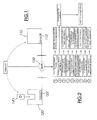
- Fig. 1 schematically shows a networked data processing device according to the invention with a server part 110 and a client part 120.
- the server part 110 and the client part 120 via a designated as WAN (Wide Area Network) telecommunication network 130, for example via the analog telephone network, via the ISDN network, via the Internet or via a satellite link to exchange data with each other.
- WAN Wide Area Network
- the server portion 110 and the client portion 120 are each assigned a unique address or identifier 112, 122, such as a telephone number, an Internet address, or the like, for the purpose of exchanging data over the WAN 130.
- the client part 120 wants to establish a connection to the server part 110 via the WAN 130, it needs information about its address 112.
- the server part 110 requires information about the address 122 of the client part 120.
- the client part 120 is configured to receive a mobile card module 140.
- the card module 140 comprises at least one memory device for non-volatile storage of data (not shown) and can exchange data with the client part 120 via a data communication device (not shown).
- the card module can be configured in particular as a chip card; but there are also other easily transportable designs into consideration. Basic characteristics of smart cards are among others in Wolfgang Rankl and Wolfgang Effing: "Handbuch der Chip Actually", Kunststoff: Carl Hanser Verlag, 2nd edition 1996 , known. The disclosure of this document is incorporated by reference into the present specification.
- the server part 120 is a computer typically associated with a commercial provider of goods and / or services.
- the server part 120 can be, for example, a computer coupled via modem or ISDN to the telephone network, which can be dialed via a dial-up line connection from the client part 120 for data communication.
- the server portion 120 is an Internet connected "World Wide Web" server (“WWW server”) that can communicate with the client portion 120 via the "Hypertext Transport Protocol"("HTTPProtocol")
- the server part is embodied, for example, as a computer connected to the Internet, via the "Simple Mail Transport Protocol"("SMTP") and via the "Post Office Protocol". (“POP”) can exchange electronic mail ("e-mail”) with the client part 120.
- WWW server World Wide Web
- HTTPProtocol "Hypertext Transport Protocol"
- POP Post Office Protocol
- the invention is not limited to particular types of telecommunication networks or to specific protocols; the above information is for illustration only.
- Fig. 3 shows a first application of the invention with reference to a schematic representation of a vararbeitungs worn invention.
- a client portion 120 is connected to a server portion 110 via a WAN 130.
- the client part 120 is provided with a display device 125 shown only schematically.
- the card module 140 received by the client portion identifies a particular end user (not shown) to whom the card module 140 is associated, personally or pseudonymically.
- an identity information 141 is stored, which can be transmitted via the WAN 130 to the server part 110.
- the identity information 141 may be additionally secured on the client part 120 side in the usual way, for example by a PIN or by biometric identity detection devices (not shown).
- card module 140 In addition to the card module 140, other card modules 140a, 140b, 140c may exist which are respectively assigned to the identities SN1, SN2 and SN3. If the card module 140 belonging to the identity SN4 141 is exchanged for one of the other card modules 140a, 140b, 140c, the respective assigned identity information SN1, SN2 or SN3 can be transmitted to the server part 110.
- the Fig. 3 illustrated first application of the invention is particularly important if an acting subject, for example, in his capacity as a contractor on the server part 110 sides at least distinguishable or should be identifiable directly or via a pseudonym.
- Fig. 4 shows a second application of the invention with reference to a schematic representation of a vararbeitungs worn invention.
- a client portion 120 is connected to a server portion 110 via a WAN 130.
- the client part 120 is provided with a display device 125 shown only schematically.
- the card module 140 picked up by the client part can, in particular, identify a specific contractual relationship AbD 141 via a predetermined data element, which in the present example includes the regular delivery (subscription) of a digital multimedia product.
- other card modules 140a, 140b, 140c may exist which are respectively assigned to the contractual relationships AbA, AbB or AbC (141a, 141b, 141c).
- the respective contractual relationship information 141, 141a, 141b, 141c is a parameter which controls an automatic selection process with respect to the file (not shown) to be transmitted from the server part 110 to the client part 120 and a multimedia representation as well as the transmission timing.
- Fig. 5 shows a fourth application of the invention with reference to a schematic representation of a vararbeitungs worn invention.
- a client portion 120 is connected to a server portion 110 via a WAN 130.
- the client part 120 is provided with a display device 125 shown only schematically.
- the card module 140 picked up by the client part identifies a particular server part 110, for example, one associated with certain service provider SPr4.
- the respective associated provider information 141a, 141b, and 141c may be transmitted to the server part 110.
- the respective service provider information 141, 141a, 141b, 141c is a parameter, which in particular causes an automatic selection process with respect to the data transmission parameters from the client part 120, so that an automatic initiation of a data exchange between client part 120 and server part 110 is made possible.
- Fig. 6 shows a first variant of an embodiment of in Fig. 1 illustrated solution according to the invention.
- a client part 120 configured to receive a card module 140 is connected to a server part 110 via a WAN 130.
- the client part 120 is provided with a display device 125 shown only schematically.
- Fig. 6 shows a solution in which the configured to receive a card module 140 client part 120 and the display device 125 form a mechanically substantially integrally executed device.
- Fig. 7 shows a second variant of an embodiment of in Fig. 1 illustrated solution according to the invention.
- a client part 120 set up to receive a card module 140 is provided.
- the client part 120 is via a data communication device 123 with a display device shown only schematically 125, which is connected to a server part 110 via a WAN 130.
- Fig. 7 Thus, a solution is shown in which the configured to receive a card module 140 client part 120 on the one hand and connected to the WAN 130 display 125 on the other hand per se form a mechanically substantially integrally executed device, the data exchange between the client part 120 and the display part 125th done by the data communication device 123.
- the data communication device come wireless and wired devices method into consideration, in particular by data transmission cable (not shown), by radio (not shown) or by infrared, eg IRDA (not shown).
- Fig. 8 shows a third variant of an embodiment of in Fig. 1 illustrated solution according to the invention.
- a client part 120 designed to receive a card module 140 is provided, which is connected to a server part 110 via a WAN 130.
- the client part 120 is coupled via a data communication device 123 with a display device 125 shown only schematically.
- Fig. 8 shows a solution in which the set up for receiving a card module 140 and connected to the WAN 130 client part 120 on the one hand and the display 125 on the other hand per se form a mechanically substantially integrally executed device, the data exchange between the client part 120 and the display part 125 is performed by the data communication device 123.
- the data communication device come wireless and wired devices method into consideration, in particular via data transmission cable (not shown), by radio (not shown) or by infrared, eg IRDA (not shown).
- Fig. 9 shows a fourth variant of an embodiment of in Fig. 1 illustrated solution according to the invention.
- a client part 120 designed to accommodate at least one card module 140 is provided, which is connected to a server part 110 via a WAN 130.
- a display device 125 which is shown only schematically and which is likewise set up to accommodate at least one card module 140.
- the client part 120 on the one hand and the display device 125 on the other hand each configured to receive a card module 140, each independently form a device that can be embodied mechanically essentially in one piece, wherein the data exchange between the client part 120 and the display part 125 by changing the card module 140 takes place.
- the map module 140 may be included in the client part 140 for storing data provided by the server part 110. After the relevant data has been stored in the card module 140, this data can be made perceptible by plugging the card module into the display device.
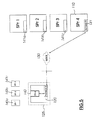
- Fig. 10 shows a fifth variant of an embodiment of in Fig. 1 illustrated solution according to the invention.
- a client part 120 set up to receive a card module 140 is provided.
- the client part 120 is coupled via a data communication device 123 to a display device 125 shown only schematically, which is connected to a server part 110 via a WAN 130.
- Fig. 10 thus, a solution is shown in which the configured to receive a card module 140 client part 120 on the one hand and connected to the WAN 130 display 125 on the other hand per se form a mechanically substantially integrally executed device, the data exchange between the client part 120 and the display part 125th done by the data communication device 123.
- the data communication device come wireless and wired devices method into consideration, in particular by data transmission cable (not shown), by radio (not shown) or by infrared, eg IRDA (not shown).
- the in Fig. 10 Client part 120 shown is adapted to receive a plurality of card modules 140a-140e which can independently initiate and control communications with server part 110 by means of the card module data (not shown) stored thereon and the communication operations initiated by server part 110 from the viewpoint of the server part 110 are addressable independently of each other.
- the card modules 140a-140e may be part of an in Fig. 4 system, ie one card module or modules serve as storage for digital but regularly asynchronous user actions by the server part 110 via the WAN 130 digital multimedia products delivered.
- a master card module 140 is provided, with which the display device 125 can identify and authenticate in a particular way with respect to the client part 120 and the remaining card modules 140a-140e inserted therein.
- the master card module 140 may be inserted into a digital book used as a display 125.
- the master card module 140 sets up the digital book in such a way that certain privileged operating processes can be performed by the user via the data communication device 123 relative to the client part or the other card modules 140a-140e inserted in it, for example enabling or disabling the client part 120 for deliveries by the server part 110 or performing ordering operations against the server part 110.
- the data communication via the data communication device 123 is preferably secured against tapping and manipulation by suitable techniques, in particular cryptographic techniques.
- Fig. 11 shows a sixth variant of an embodiment of the in Fig. 1 illustrated solution according to the invention.
- a client part 120 designed to receive a card module 140 is provided, which is connected to a server part 110 via a WAN 130.
- the client part 120 is coupled via a data communication device 123 with a display device 125 shown only schematically.
- Fig. 10 shows a solution in which the client part 120 set up to receive at least one card module 140, on the one hand, and the display device 125 connected to the WAN 130, on the other hand, each mechanically separate itself form integrally executed device, wherein the data exchange between the client part 120 and the display part 125 is performed by the data communication device 123.
- the client part 120 as well as in the in Fig. 10 in the case illustrated, for accommodating a plurality of card modules 140a-140e which, by means of the card module data (not shown), each independently initiate and control communication operations with the server portion 110 and which, in the communication portion initiated by the server portion 110, from the perspective of Server parts 110 are addressable independently.
- the card modules 140a-140e may be part of an in Fig. 4 system, ie one card module or modules serve as storage for digital but regularly asynchronous user actions by the server part 110 via the WAN 130 digital multimedia products delivered.
- the client part 120 it proves to be particularly advantageous to implement the client part 120 as a stationary card module station which is essentially permanently connected to the WAN 130 and thus can always initiate data communication operations with respect to the server part 110 and, in addition, asynchronously initiates data communication operations initiated by the server part 110 User actions can be accepted by the user, even if the display device 125 is designed as a mobile device, which leads the user even in the absence of location.
- FIGS. 12 and 13 show the FIGS. 12 and 13 in each case a variant in which a client part 120 without its own card module is used.
- Fig. 13 1 shows a client part 120, which is set up to receive a complete display device 125, the display device 125 in turn being set up to receive at least one card module 140.
- Data communication between server portion 110 and card module 140 proceeds in a manner in which the exchanged data is passed through display 125 through appropriate electronic precautions.
- the client part 120 is set up to accommodate a complete display device 125.
- the data exchange between client part 120 on the one hand and for receiving at least one card module 140 prepared display device 125 on the other hand, for example, as in Fig. 13 represented by means of a data communication device 123 can be realized.
- the data communication device come wireless and wired devices method into consideration, in particular by data transmission cable (not shown), by radio (not shown) or by infrared, eg IRDA (not shown).
- FIGS. 14 and 15 show further variants of an embodiment of in Fig. 1 illustrated solution according to the invention.
- Fig. 1 is also shown in Fig. 14 provided for receiving a card module 140 client part 120 which is connected via a WAN 130 with a server part 110.
- a display device 125 is also connected to the WAN 130a.
- the WAN 130 may be identical to the WAN 130a.
- An interaction with the server part 110 triggered via the display device 125 and transmitted via the WAN 130a results in the transmission of multimedia data from server 110 via the WAN 130 to the client part 120.
- This allows the user (not shown) to retrieve data from the server part 110, for example which are transmitted via the WAn 130 to the client part 120 set up at home, for example.
- Fig. 15 shows a variant in which the client part 120 is provided with a display device 125.
- the transmission of the data retrieved at the server part 110 (not shown) is made via the WAN 130 to a secondary client part 120a.
- FIGS. 3 to 5 illustrated application modes of the invention can in principle with each of the in the FIGS. 6 to 15 realized variants are realized.
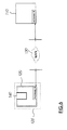
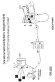
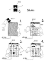
- FIG. 16 schematically shows a first embodiment of the solution according to the invention.
- a digital book 510 is provided with a receiving device (not shown) for a card module 140.
- a digital book of the type shown is, for example, in WO-A1-99 / 15982 disclosed; The disclosure of this document is expressly incorporated by reference.
- the digital book 510 is controlled by data stored on the card module 140.
- a catalog of different possibilities stored for example in the card module 140 or stored on the card module 140 by the server part 530 is displayed, and print media or digital multimedia products are regularly sent by a service provider 520 allow.
- the user (not shown) then has the option, for example, to select an alternative via an actuation of the touchscreen of the digital book 510 and to express his or her intention of being supplied regularly in a predefined manner in the future. In doing so, the user determines all necessary data regarding the intended business, such as type, scope, delivery route and payment method.
- the data describing the intended business is then transmitted via the WAN 130 to a server 530 of the service provider 520.
- the digital book 510 may be provided, for example, with an internal modem (not shown) which is connected via a connecting cable 540 to the public telephone network acting as WAN 130, the data being routed directly to the server 530 via telephone lines.
- Other data communication paths are suitable;
- the digital book 510 may be accessed via the Connection cable 540 or via an IRDA connection to a mobile phone instead of the telephone landline coupled.
- a feedback with confirmation data from the server 530 may be provided in the same or a different way. Depending on the technical and legal conditions, this data exchange can be repeated until the completed data exchange represents a completed transaction.
- connection between the digital book 510 and the server 530 may be removed.
- transaction completion phase may be used to arrange for the regular delivery of physical print products, audio and video carriers 550 to a postal delivery address by a supplier 560 who need not be identical to the service provider.
- a technical aspect of the agreed regular delivery ("subscription") of data processing programs, texts or multimedia data is that the initiative to transfer a particular file currently intended for distribution should not always necessarily come from the user ("pull”). but at least optionally also from the server 530 ("push").
- a complete "push" delivery of the multimedia data due for delivery is possible.
- the user always keeps a data processing system or a part of a data processing system connected to a suitable WAN 130, for example the telephone network, in order to be able to receive and store deliveries of multimedia data that are initiated at any time by the server 530.
- the multimedia data stored in this way can then be consumed, for example, by means of the digital book 510.
- the user can then establish a connection to the server 530 via the WAN 130, actuate a suitable control element (not shown) and thereby cause the server 530 to deliver the desired file via the existing communication channel established by the client part 120 ("On -Demand delivery ").
- a variant of the "on-demand delivery” then consists in that the user initially establishes a connection to the server 530 as usual, transmits a data item indicating a request for delivery by actuating a control element and then terminates the connection to the server 530.
- the transmission of the desired file then takes place at a later time by a communication channel established by the server 530.
- a "broadcast" variant is possible in which the server tries to transfer a file to a plurality of client parts 120. This can be easily realized especially in radio-based systems. It is then at each individual client part 120, depending on the effective default settings, in particular depending on the data stored in the card module 140 to actually save a file transferred to all or ignore it.
- a delivery of a desired file can be initiated by push or in broadcast mode, for example by inserting a correspondingly preset card module 140 into the client part 140. It is then waited until the transmission by individual addressing, ie push, or to all, ie broadcast, is completed by the server 530.
- On-demand retrieval With or without call back by the server 530, it is necessary for the user to first communicate his request for delivery to the server 530 via the client part 120 and then to compute the desired file directly or at a later time. In this alternative, the call can also to the input of a PIN or the like. to secure the entitlement.
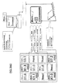
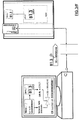
- Fig. 18 schematically shows details of a further variant of the first embodiment of the inventive solution Fig. 16 with the book station 610.
- the book 510 is used in the book station 610.
- the book station 610 is coupled to the digital book 510 via a data communication device (not shown), wherein the data accessed from the book station 610 through the digital book 510 can be accessed on the card module 140 inserted into the digital book 510.
- a controller not shown
- both each contain a control device.
- the book station 610 has a connection to the WAN 130.
- the digital Book 510 in the inserted state by the book station beyond powered.
- the server 530 can be transferred to the via the WAN 130, the book station 610, and the digital book 510 Map module 140 and store it in multimedia data (not shown).
- Fig. 18 shown variant can be used meaningful especially if the additional effort for a card station 620 should be avoided and if the digital book 510 is not required for sufficiently large periods of time by the user for other purposes, so that it placed in the book station 610 and this can be connected to the WAN 130.
- an agreement with the service provider 520 could be to initiate data transfers initiated by the server 530 only at the night hours, so that the user can use the digital book 510 for other purposes during the day and at night at the book station to receive from the server 530 on a regular basis transmitted multimedia data.
- the card module 140 legitimizes the service provider by means of predetermined data elements stored therein. When neutral card modules 140 are delivered to the user without predetermined data items, provision may be made to have the data items subsequently set by the user by means of an electronic book or notebook etc., for example, by specifying individual service providers with whom business relationships should be possible.
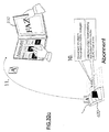
- Fig. 19 schematically shows details of a further variant of the first embodiment of the inventive solution Fig. 16 With the wearable computer 630.
- mobile computers such as notebooks or palmtops are easily portable and many have overcome the limitations associated with the operation of stationary computers, there is a need for computers that are even easier to use on the go.
- the term "wearable" calculator means devices that can be integrated, for example, in the clothing or attached to it, so that no footprint on a table or the like is required.
- Conventional data input or output concepts based on keyboard and conventional display technology are generally not applicable to this category of devices.
- Fig. 19 shows by way of example a wearable computer 630, which can be worn for example on a clothing belt.
- the wearable computer 630 does not have its own display, which would be suitable for displaying a larger contiguous area of a document; Rather, a cable 635 is provided, via which an external display (not shown) can be connected.
- the wearable computer 630 may be provided with (a few) controls 640 and a small auxiliary display 645.
- the wearable computer 630 can be set up to receive a card module 140.
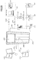
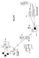
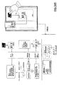
- Fig. 20 schematically shows a second embodiment of the solution according to the invention.
- an action terminal 810 is provided in the public space within a building or in the outer space, which typically has at eye level a display device 820 designed as a touch-sensitive display.
- the action terminal 810 may be configured such that a catalog of directly acquired multimedia works is displayed on the display 820. If the action terminal is provided with a card module magazine (not shown), after input of the purchase request, for example via the touch screen and after payment, for example by chip card (not shown) a card module 140 removed from the card magazine, with the file representing the desired multi-media work provided and output via an output slot 830.
- a card module magazine not shown
- chip card for example by chip card
- Another variant of this embodiment provides to provide the card module 140 with a certain suitable cryptographic key instead of a file representing a data processing program, a text or multimedia work, with which the otherwise in encrypted form transmitted file can be decrypted again.
- This approach has the advantage that card modules 140 with relatively little storage capacity, such as conventional smart cards, can be used.
- a card module reading station 830 into which a card module 140 already in the possession of the user is inserted. After the copying of the desired data processing program, text or multimedia work representative file or even just a certain suitable cryptographic key, with which the otherwise encrypted file transmitted file can be decrypted again, the card module 830 is removed again.
- the multimedia work may then be consumed by insertion of the card module 140 into the digital book 510a by the user.
- the ordering and delivery process may also be performed by means of a digital book 510b connected to the action terminal 810 via a cable 840.
- the action terminal 810 may have a local mass storage such as a hard disk (not shown) on which the multimedia works offered for sale are held in the form of digital data.
- a local mass storage such as a hard disk (not shown) on which the multimedia works offered for sale are held in the form of digital data.
- the order data can in particular be transmitted via the WAN 130a to the server 530 of the service provider 520, from where the transmission of the files representing the multimedia works is controlled.
- the decryption process only granted to the rightful user is done after transferring the multimedia data 580 representing the work to be delivered over a WAN 130a (which may or may not be identical to the WAN 130 used for ordering).
- the delivery process for the file 580 may also be done directly from the action terminal.
- the transmission of files from the server 530 to the action terminal 810 can also be made possible.
- the WAN 130a, the WAN 130b, and the WAN 130c may be identical or different.
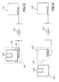
- FIG. 21 shows a further variant of the solution according to the invention. Show in detail FIGS. 21a to 21f an arrangement according to the invention in different phases in the settlement as an example of selected electronic mail, also called "e-mail". It is understood that the process shown is also applicable when retrieving computer programs, texts or multimedia works from a service provider.
- Fig. 21a 1 shows a client part 120 and a card module 140 implemented in the form of a chip card.
- the client part 120 is provided with an inserted adapter part 121, which has a line 122 which is connected to a WAN 130, for example the telephone network.
- Fig. 21b shows the arrangement Fig. 21a after insertion of the card module 140 in the client part 120.
- the client part 120 is automatically turned on and activated, provided the adapter part 121 is inserted, which is indicated by a first display element 123a, such as a light emitting diode, ie, the arrangement is ready to establish a connection via the line 122.
- a first display element 123a such as a light emitting diode, ie
- Fig. 21c shows the arrangement Fig. 21b during the download of e-mail messages (not shown) stored on the server portion 110 via the WAN 130 and the client portion 140 to the card module 140.
- the data (not shown) stored in the data memory (not shown) of the card module 140 controls the Dial-in operation to an e-mail server part 110 of an e-mail service provider via the WAN 130.
- the dial-in process is preferably started only when the user (not shown) releases this process by actuating a control element 124 provided for this purpose, for example an actuating button .
- the temporal extension of the download is indicated, for example, by a flashing signal of a second display element 123b, for example a light-emitting diode.
- the card module 140 is for this purpose provided with a sufficiently large data memory (not shown), which may be embodied for example as a flash memory.
- Fig. 21d shows the arrangement Fig. 21c during the uploading of e-mail messages previously stored in the card module 140.
- the temporal extension of the process of uploading e-mail messages is indicated, for example, by a blinking signal of the first display element 123a.
- Fig. 21e shows the arrangement Fig. 21d after the removal of the data connection via the WAN 130 to the server part 110.
- the illumination of the first display element 123a indicates that the client part 120 is still turned on since both the card module 140 and the adapter part 121 are still plugged in.
- Fig. 21f shows the arrangement Fig. 21e after the removal of the adapter part 121 from the client part 120.
- the client part 120 is now turned off and the first display element 123a goes out, ie the client part 120 can be easily transported with the card module 140 inserted in the off state, if the adapter part 121 is pulled out because of The adapter part 121 switches on or off the power supply of the client part 120 via a suitable switch device (not shown).
- a modified variant of the solution according to the invention can be obtained by using in the in Fig. 21c phase e-mail messages uploaded to server 110 via SMTP and at the in Fig. 21d phase e-mail messages are downloaded from the server 110 via POP3, ie the order shown is exchanged.
- Fig. 22 shows a further variant of the solution according to the invention, which in the basic features of in Fig. 21 shown variant corresponds. in the single show FIGS. 22a to 22f an inventive arrangement exemplarily in different phases in the processing of electronic mail.
- the client part 120 is at the in Fig. 22 variant provided with a numeric keypad 124a and with a text display 123c.
- this makes it possible to make the establishment of a data connection from the client part 120 to the server part 110 dependent on the unlocking of the user and access data stored in the card module 140 by entering a PIN. This can significantly reduce the risk of misuse and unauthorized downloading or uploading of e-mail messages.
- the display device 123c short texts can be displayed, which inform the user about the currently running processes.
- the technical handling of uploading and downloading e-mail messages can be handled on the basis of proven technical standards, such as SMTP for uploading (delivering) electronic messages and POP3 for downloading (delivering) electronic messages.
- a modified variant of the solution according to the invention can be obtained by using in the in Fig. 22c phase e-mail messages uploaded to server 110 via SMTP and at the in Fig. 22d phase e-mail messages are downloaded from the server 110 via POP3, ie the order shown is exchanged.
- News on the in the FIGS. 21 and 22 shown manner to be transmitted to the server part 110 or downloaded from this, must first be written to the data memory of the card module 140 before uploading or read after downloading from the data memory of the card module 140.
- Fig. 23 shows two variants for reading from the server part 110 downloaded e-mail messages.
- the client part 140 provided with the card module 140 can be embodied such that it can be introduced as a whole into a correspondingly configured display device 125a, wherein both the client part 120 and the display device 125a can exchange data via a suitable data communication device (not shown).
- Another variant provides that the user (not shown) removes the card module 140 from the client part 120 and inserts it into a display device 125b.
- Both the display device 125a and the display device 125b have suitable software for reading out and displaying the e-mail messages stored in the map module 140.
- the display device 125b may be, in particular, a notebook (not shown) provided with a card module receiving device or a digital book (not shown) provided with an e-mail message presentation program.
- Fig. 24 schematically shows devices for encryption and decryption of copyrighted (multimedia) works representing files involving the card module 140.
- multimedia files representing files (not shown) are stored.
- a card module 140 may be provided with a tamper-resistant physical random number generator (not shown) to generate a random number for which a key pair with a public and a private key is calculated in the card module.
- the calculated keys are stored in the memory device (not shown) of the card module 140. However, it is also possible to store externally generated keys in the card module 140. If the available storage space permits, multiple key pairs may be stored in the memory of the card module 140.
- a public key 710, 711, 712 associated with this file can first be read from the card module 140 and transmitted to the server part 110a, 110b.
- the file in question is encrypted using the particular public key 710, 711, 712 associated with the file.
- the cipher can now be distributed without hesitation over a WAN; possibly copies made without authorization by third parties are unusable without possession of the corresponding private key.
- the decryption of the encrypted file 720 with the associated private key can be performed directly with the processor provided in the card module 140. This has the great advantage that for this the corresponding private key does not have to be made available outside of the card module 140, so that no security risks arise with regard to unauthorized copying of the private key.
- the disadvantage is that when using a smart card with an 8-bit chip card processor as a card module 140, the processing capacity is low and the decryption process can take a long time.
- the card module 140 may be convenient to implement the card module 140 in two parts, with a smart card used only to store the key pairs where the decryption process is performed by a more powerful cryptographic processor 750 provided in a cryptographic processor component 740.
- a smart card used only to store the key pairs where the decryption process is performed by a more powerful cryptographic processor 750 provided in a cryptographic processor component 740.
- this PCMCIA plug-in card can be designed in such a way that the chip card carrying the cryptographic keys is designed to be pluggable therein.
- the cryptography processor component 740 may then use the public key of the cryptographic processor component 740 to encrypt the private key intended for decrypting a file.
- the cryptographic processor component 740 then decrypts the ciphertext of the private key intended to decrypt a file, thus recovering that private key.
- the cryptographic processor component 740 can be provided in the corresponding memory devices manufacturers invariable digital Authetizticiansmerkmale introduced by cryptographic digital signatures and corresponding key certificates, each the relationship between an authorized manufacturer or issuer and a public signing keys testify, are accredited.
- the archive 760 for storing programs, textual or multimedia works representing encrypted files 720 may be formed as a separate archive storage unit 770 and preferably comprise a non-volatile memory (buffered RAM, EEPROM, flash memory, hard disk storage, etc.).
- Reference numeral 780a denotes a combined functional unit including key generation, secure key storage, and key management together with bulk data encryption and decryption.
- Reference numeral 780b denotes another combined functional unit that includes bulk data encryption and decryption, along with storage of the encrypted files 720-725.
- Reference numeral 780c designates another combined functional unit that includes key generation, secure key storage and key management, along with bulk data encryption and decryption, and storage of the encrypted files 720-725.
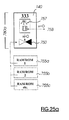
- FIGS. 25a to 25f are different embodiments of cryptographic devices Fig. 24 removable.
- Fig. 25a shows a card module 140 provided with a cryptography processor 750.
- the data to be decrypted are stored in memory devices 755a, 755b, 755c outside the card module 140, whereas the cryptographic keys 757 are stored in the memory of the chip card 140.
- Fig. 25b shows a variant in which the chip card 140 can be inserted into a hardware expansion module 759.
- the hardware expansion module 759 may be implemented in a PCMCIA card incorporating the cryptographic processor 750 and memory 755 for data to be decrypted; however, the data to be decrypted may also be supplied externally from a memory 755a.
- the cryptographic keys 757 are stored on the smart card 140.
- Fig. 25c variant shown differs from that in Fig. 25b shown arrangement in that the memory 755 is arranged for the data to be decrypted, for example as a flash memory on the chip card 140.
- Fig. 25d variant shown differs from that in Fig. 25c shown arrangement in that the memory 755 for the data to be decrypted, for example, as a flash memory in a card module 140 can be inserted.
- Fig. 25e variant shown differs from that in Fig. 25a shown arrangement in that the memory 755 is provided for the data to be decrypted, for example, as a flash memory on the card module 140.
- Fig. 25f variant shown differs from that in Fig. 25d in that the key memory 757 is provided on the hardware expansion module 1759.
- the keys may also be fed directly to the cryptographic processor 750 via appropriate data links 758.
- the cryptography processor 750 may also be used for encryption.
- the memories 755 then contain data to be encrypted.
- Fig. 26 schematically and exemplarily shows a flow of transmission and decryption of an encrypted file representing a work.
- the exemplary in Fig. 1 sketched solution according to the invention can be used for the benefit of billing the use of services provided by third parties.
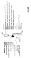
- Fig. 27 schematically shows a flowchart of a first method for billing the reference of software, text or multimedia works representing files from a server part 110. It will be with reference to Fig. 24 It is assumed that the server part 110a or 110b provides a software, text or multimedia file 720 in encrypted form that is useless to the user without prior decryption. As in Fig. 27 In the first method, in step 1100, the file 720 is downloaded from the server part 110. It assumes that the file contains both the encrypted work and an unencrypted identifier that uniquely identifies the work. This identifier, for example in the form of a data element representing a rights number, is extracted from the file in step 1110.
- step 1120 After plugging the card module 140 into the client part, in step 1120, an in memory (not shown) of the Card module 140 stored table with individual identifiers for which the relevant card module 140 embodies a user right read. Step 1130 then checks to see if the identifier found in step 1110 is included in the single identifier table stored in the memory (not shown) of the card module 140. If the test is positive, the associated private key is loaded in step 1140 and the file 720 is decrypted in step 1150. In step 1160, the decrypted plaintext of the file 720 may then be displayed or otherwise used. If the rights check fails in step 1130, an error message occurs in step 1170. In this case, the end user has no right to use the work corresponding to file 720.
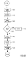
- Fig. 28 schematically shows a flowchart of a second method for accounting for the reference of software, text or multimedia works representing files from a server part 110. It will be with reference to Fig. 24 It is assumed that the server part 110a or 110b provides a software, text or multimedia file 720 in encrypted form that is useless to the user without prior decryption. As in Fig. 27 In the first method, in step 1100, the file 720 is downloaded from the server part 110. It assumes that the file contains both the encrypted work and an unencrypted identifier that uniquely identifies the work. This identifier, for example in the form of a data element representing a rights number, is extracted from the file in step 1110.
- step 1120 After plugging the card module 140 into the client part, a table with individual identifiers, stored in the memory (not shown) of the card module 140, is opened in step 1120 the card module 140 in question embodies a usage right. Step 1130 then checks to see if the identifier found in step 1110 is included in the single identifier table stored in the memory (not shown) of the card module 140. If the rights check fails in step 1130, an error message occurs in step 1170. In this case, the end user has no right to use the work corresponding to file 720.
- step 1210 a table of individual identifiers, stored in the memory (not shown) of the card module 140, for which the card module 140 embodies a right of use, determines a credit value specific to the global or specific identifier. With a balance equal to zero, an error message is output in step 1225. With a credit greater than zero, the associated private key is loaded in step 1230 and the deciphering of the file 720 is completed. Now the decoded plaintext file 720 can be displayed or otherwise used. In step 1240, use is enabled for a predetermined amount of time. Thereafter, in step 1250, the credit is reduced by one unit.
- step 1260 If the user has now set the usage, this is determined in step 1260 and in step 1270 the decrypted file is deleted or otherwise made unavailable. The file 720 remains in encrypted form. If the user wishes to continue usage, a check is made in step 1280 to see if there is a credit greater than zero, and if so, a continuation to step 1240.
- FIG. 12 is a perspective view of a hardware expansion module 759.
- FIG Fig. 25 with a chip card 140 as a card module.
- an operating element 759a for example a key, may be provided.
- Fig. 30 shows a schematic flow chart of an exemplary subscription order process.
- Fig. 31 shows a schematic flow diagram of a first variant of a subscription processing by means of the inventive solution.
- Fig. 32 shows a schematic flow diagram of a second variant of a subscription processing by means of the inventive solution.
- Fig. 33 shows a schematic flow diagram of a third variant of a subscription processing by means of the inventive solution.
- FIG. 34 shows in the sub- FIGS. 34a to 34h schematically procedures in connection with the settlement of delivered files in the context of the inventive solution.
- the show FIGS. 34a to 34c a variant in which the use of the work is billed according to usage time.
- Fig. 34c Figure 11 shows the view of the display part 125 with an indication of the card number and the remaining credit units in an upper display line 125a and a display of the time, the author number and the usage time and usage fees previously accumulated at this work.
- the amount of the user charges can be dependent on the time dependency and the volume-dependent billing.
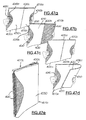
- Fig. 35 shows in the sub- FIGS. 35a to 35c a data processing device according to the invention with a wearable computer 1010.
- the wearable computer 1010 has a wearable computer housing 1015, which is flat, with rounded edges and slightly curved concave, so that it can be easily worn, for example, with a belt 1017 on the body.
- a wearable computer housing 1015 which is flat, with rounded edges and slightly curved concave, so that it can be easily worn, for example, with a belt 1017 on the body.
- Other shapes of the housing 1015 are possible, provided that the computer can be easily worn on the body. In particular, those forms are contemplated that allow sewing or insertion of the wearable computer 1010 into garments.
- the exemplarily illustrated wearable computer 1010 has a display 1020 and, for example, control elements 1030a, 1030b and 1030c designed as buttons. Also, a light-emitting diode 1040 may be provided as a status indicator.
- the exemplary wearable computer 1010 has a receiving device (not shown) for a card module 1050.
- Fig. 35b shows the holder of the wearable computer 1010 on a belt 1017 by means of a housing 1015 suitably fixed to the retaining strap.
- Fig. 35b also shows a dirt and splash protection by means of a top of the housing 1015 of the wearable computer 1010 plugged protective cap 1070.
- Fig. 35b shows Fig. 35b a double-leafed hand book 1080 in the manner of a digital book, the book-like by a hinge device 1081 openable and can be folded and connected via a cable 1082 with the wearable computer 1010 and which is held by the user 1084 in the hand.
- the two-bladed handpiece 1080 may be provided with two display displays 1086a, 1086b, each one essentially form the insides of the two wings.
- the hand piece 1080 can be made particularly simple, thin, and lightweight.
- Fig. 35c shows a user 1084 who wears the wearable calculator 1010 on a shoulder strap 1017 while holding the handpiece 1080 operatively and readable in the hand, with the right hand operating rearwardly located controls.
- FIG. 36 shows in the FIGS. 36a to 36c Variants of in Fig. 35 shown data processing device as a one-piece embodiment with a display, wherein the hand parts of the FIGS. 36a and 36b can be designed both with and without its own power supply (for example, accumulator or dry battery).
- power supply for example, accumulator or dry battery
- FIGS . 36a to 36c show a wearable computer 1010, which cooperates with a single-winged handpiece 1080a, with different and combinable control options are specified.
- Fig. 36a shows symbolically arranged on the back of the handpiece 1080a arranged controls 1090, which may be performed for example in the form of three push buttons 1090a, 1090b and 1090c.
- the keys 1090a, 1090b, 1090c are arranged in the gripping hand region of a hand 1084a of a user 1084.
- the keys are individually operable, for example, to trigger a scroll up function by key 1090a, to trigger a scroll down function by key 1090c, and to trigger a menu provide function by key 1090b.
- the keys 1090a, 1090b and 1090c may also be operable together or in combination with other input means such as a touch-sensitive screen (not shown) or a microphone voice input device to trigger other functions, such as by simultaneously operating two or three keys ,
- a touch-sensitive screen not shown
- a microphone voice input device to trigger other functions, such as by simultaneously operating two or three keys
- the embodiment shown by way of example also shows a cable connection which supplies the handset with energy and allows bidirectional data communication. It is left open whether the handset has its own accumulator or dry battery or the like. In such a case, if necessary, the power source can be charged indirectly via the wearable computer.
- Fig. 36b 13 shows a variant which, in addition to the cable 1082, enables a wireless data connection between the wearable computer 1010 and the handset 1080a.
- This wireless data connection can be effected in particular by a radio-frequency radio link, for example according to the "Bluetooth" standard, or by an infrared link, for example according to the IRDA standard.
- the wearable computer 1010 has a transceiver 1095a at a suitable location.
- the handpiece 1080a also has, at a suitable location, a transmitting / receiving device 1095b, which is suitably chosen for the transmitting / receiving device 1095a of the wearable computer 1010.
- the data communication of the handset and / or the wearable computer remote or external devices or devices such as the Internet, other personal computers, printers, etc. over a wireless LAN (Local Area Network) or WAN (Wide Area Network) while the communication between handset and wearable computer is accomplished via cable 1082.
- a wireless LAN Local Area Network
- WAN Wide Area Network
- FIG. 12 shows the operation of the handle 1080a by a push pin 1094 guided by a hand 1084a of a user 1084 on a pressure sensitive surface 1087.
- Fig. 36c shows a modification of the in FIGS. 36a and / or 36b data processing device , in which the cable 1082 has been dispensed with. While it is in the provided with a cable variants in the FIGS. 35 and 36a 26b, it is possible to supply power to the handpiece 1080 or 1080a from a current source (not shown), for example an accumulator or a dry battery, arranged in the wearable computer 1010 Fig. 36c illustrated embodiment or use a separate power supply of the handpiece 1080a, for example, by an arranged in the handpiece 1080a accumulator, the center of gravity and Lasttechnikssentn is preferably provided in the handle.
- a current source not shown
- a current source for example an accumulator or a dry battery
- FIG. 12 shows the operation of the handpiece 1080a by a finger 1084b of a hand 1084a of a user 1084 on a pressure sensitive surface 1087.
- FIGS. 36d and 36e show more variants of the in the FIGS. 36a to 36c illustrated embodiments, but with a double-winged handle 1080, wherein in Fig. 36e the accumulator or theterbatterie.aus gravity and load reasons preferably in the hinge area (hinge) is housed.
- FIG. 37 shows in the FIGS. 37a to 37c a further variant of a data processing device according to the invention. Unless otherwise indicated, the reference numerals given here correspond to those in the FIGS. 35 and 36 used reference numerals.
- FIG. 37 an application of the data processing device in which the handpiece 1080 is placed in the manner of a notebook, ie, a first wing portion 1086b rests on a flat surface, such as a table surface, whereas a second wing portion 1086b is placed vertically.
- the individual embodiments can be combined as desired in a further embodiment with respect to the operation and the corresponding design (not shown).
- the inward-facing surface of the first wing portion 1086b is pressure-sensitive, and the user 1084 applies a pressure pin 1094 thereto with his hand, thus performing data entry.
- the inward-facing surface of the first wing portion 1086b is provided with the functionality of an input keyboard, and the user 1084 enters data input with his / her hand 1084a.
- the execution of the keyboard is open as a virtual keyboard, which is operated via a sensitive input surface or as a real keyboard with mechanically operated keys.
- the inward-facing surface of the first wing portion 1086b is provided with the functionality of a touchpad, and the user 1084 makes a data entry with a finger 1084b of his hand 1084a.
- the example shows a dargestllter displayed on the display cursor, which indicates the relative position of the finger movement on the designed as a touchpad second wing part (book cover).
- Fig. 38 1 shows a view of a first variant of a data processing system according to the invention with a wearable computer 1010 and a handpiece 1080, which are connected via a cable 1082 ( FIG. Fig. 38a ) or wirelessly ( Fig. 38b ) are interconnected.
- This first variant represents a particularly cost-effective solution, in which the handpiece 1080 can be used only in cooperation with the wearable computer 1010.
- the cable 1082 not only allows data exchange between the handpiece 1080 and the wearable calculator 1010;
- the power supply of the handpiece 1080 is possible via the cable 1082 from a current source, for example an accumulator, arranged in the wearable computer 1010.
- the handpiece 1080 can be built very low in weight.
- the weight of the required power source does not necessarily lead to a loss of operating convenience. If the cable 1082 is avoided, must - as in Fig. 38b a wireless data connection is provided between the handset 1080 and the wearable computer 1010. It is also necessary to provide a power source (not shown) in the handpiece 1080.
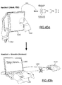
- Fig. 40 2 shows a view of a second variant of a data processing system according to the invention with a wearable computer 1010 and a handpiece 1080, wherein the handpiece 1080 can also be used by itself ( Fig. 40a ) or wirelessly and / or with a cable 1082 to a wearable computer 1010 ( Fig. 40b ).
- Fig. 40a schematically shows a use of the handpiece 1080 as an autonomous digital book.
- Fig. 40b shows a coupled system of handpiece 1080 and wearable calculator 1010.
- the wearable calculator 1010 Due to the additional data processing capacity of the wearable calculator 1010, it is now possible to turn the handpiece 1080 into a high-performance notebook computer, without the need for the required computing capacity of initially provided in the handpiece 1080. It is therefore possible to provide an autonomous, yet cost-effective handset 1080, such as an "eBook” for reading book, magazine newspaper and document information and / or an internet tablet for "surfing" on the Internet and / or a PDA (Personal Digital Assistant) for reading and writing notes, for appointment management, etc., if necessary by coupling with the wearable calculator 1010 can be increased to a powerful overall system.
- the handset contains only a browser or another operating system than in the wearable computer. The operating system can be switched by or after pairing automatically or in response to an input and / or it complements or extends the active operating system located on the handset.
- Fig. 41 shows a highly schematic block diagram of the in Fig. 39 illustrated second variant of a data processing system according to the invention.
- CPU central processing unit
- RAM random access memory
- EASI system bus
- peripheral components that can be used in the wearable expansion device can each be permanently installed therein or else modularly upgradeable or convertible.
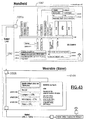
- Fig. 43 shows a highly schematic block diagram of the in Fig. 42 illustrated third variant of a data processing system according to the invention.
- the above statements apply FIGS. 39 and 41 with reference.
- Fig. 43 On the other hand, however, it is shown that only the handpiece 1080, but not the wearable expansion device 1010a, has its own central processing unit (CPU) together with memory (RAM / ROM) and system bus (EASI).
- CPU central processing unit
- RAM / ROM random access memory
- EASI system bus
- Fig. 44 schematically shows a data processing device 3000 according to the invention for the selection and ordering of goods or services that can not be provided directly through data lines, such as the delivery of physical goods or the provision of services such as a taxi ride or an order and / or reservation of, for example, cinema or Theater tickets or table reservations in a restaurant or purchase orders to retail outlets and / or large-scale distributors like wholesale chains or department stores.
- the data processing device 3000 comprises a handset 3020 operated by an operator 3030, and a card module 3010 having at least one non-volatile data storage device (not shown) and typically outputable by the supplier or service provider. But it is also possible that the card module is issued by third parties.
- the handset may be configured, for example, as a digital book or palmtop or PDA or notebook or mobile phone, and includes a computer including display 3040 and suitable input means, e.g. a touch screen.
- the handpiece serves as a universal information, ordering and reservation means and is advantageously equipped with a suitable data communications medium with or without cable.
- a low-cost possibility exists in the data communication over the fixed net.
- a device can be provided which enables both telephoning and / or data communication at the same time.
- a suitable transmission protocol may be provided which allows such simultaneous transmission.
- Fig. 44a schematically shows the handpiece 3020 after insertion or coupling of the card module 3010 in or on a dedicated coupling device (not shown).
- the data processing device together with the software running on it for example, be set up such that by the plug-in or Ankoppelvorgang via a suitable telecommunication device (not shown), a connection to a server computer (not shown) of the provider is established. Thereafter, a catalog of orderly goods and / or services may be automatically downloaded from the server computer (not shown) to the memory of the card module (not shown) and / or memory (not shown) of the handset 3020 and conveniently displayed on the display 3040 can. Immediately after the end of the download process, the connection to the server computer can be automatically interrupted to save on telecommunications costs.
- the data processing system may for example be configured such that it is, for example, via a telephone line by modem (not shown) or ISDN adapter (not shown) or even wirelessly via a GSM mobile phone module (not shown) directly into the server computer dials and records using appropriate protocols data communication with the server computer.
- modem not shown
- ISDN adapter not shown
- GSM mobile phone module not shown
- URL Uniform Resource Locator
- a stored in the non-volatile memory (not shown) of the card module 3010 information for example in the form of at least one telephone number and / or Intemet address the fully automatic construction of the data communication with the server computer and downloading the catalog as soon as the card module 3010 is inserted into the handpiece 3020 or coupled to this.
- the user 3050 is thereby relieved of the need to remember phone numbers, internet addresses, and telecommunications operations and navigation.
- FIG. 12 shows an operation in which the user 3050 changes to a mode in which he can view the catalog on the display 3040 by pressurizing the touch screen display 3040 in a mode.
- Fig. 44c shows a subsequent operating step, in which the user has selected or selected individual orderable goods and / or services from the catalog and causes an order.
- the data processing device 3000 in turn - as already in the catalog download - fully automatically a telecommunication connection to the server computer (not shown) ago and transmits the order data.
- the server computer returns an order confirmation to the data processing device 3000.
- Fig. 45 schematically shows a flowchart of a selection and ordering process with in Fig. 44 represented data processing device.
- the successive steps are indicated in their sequence-dependent order by enclosed in rectangles texts.
- For the individual steps require input values specified by the texts in the diamonds.
- FIG. 47 shows in the FIGS. 47a to 47e the back and outer view of the housing of various variants of inventive digital hand parts 4010a to 4010d.
- the illustrated digital hand parts 4010a-4010d comprise at least one areal display unit (not shown) for displaying digital information and are intended to be held by the user with one hand or both hands.
- digital handpieces also include input means, such as input keys 4020.
- digital hand parts can also be executed as full-fledged computers including power source, central processing unit, memory and other peripherals.
- an inventive digital handset for displaying digital information an Internet tablet, a mobile phone, a PDA or a Notbebook computer as well as all other known or conceivable mobile display devices are considered, if they are intended in any form for hand-held operation, eg in use as a reader for an "e-book”.
- Fig. 47a shows a back view of a two-leaf digital handpiece 4010a with a first wing 4030a and a second wing 4030b, which are buchartig on a hinge part 4030c towards the user and foldable.
- the left hand and right hand gripping areas shown shaded are realized on the case back by a lip-shaped first case back surface area 4040a, 4040b, whereas the remaining case back surface is shown unshaded and forms a second case back surface area 4050a, 4050b.
- Operating buttons 4020 are arranged on the first housing back area. It proves expedient to design the first housing back surface area 4040a, 4040b differently with respect to the material used than the second housing back surface area 4050a, 4050b.
- case back surface portions corresponding to the first case back surface portion 4040a, 4040b will be referred to as “gripping portion”, whereas case back surface portions corresponding to the second case back surface portion 4050a, 4050b will be referred to as “ceiling portion”.
- grip portion case back surface portions corresponding to the first case back surface portion 4040a, 4040b
- ceiling portion case back surface portions corresponding to the second case back surface portion 4050a, 4050b
- Deviating from the lip shape embodiments are also possible; however, the lip shape shown is considered to be a preferred embodiment.
- Fig. 47b shows a first variant of in Fig. 47a shown housing back, in which a single-winged digital handset 4010 b is provided with a wing 4030.
- This 4030 wing can be protected from dirt and damage by a foldable 4060 flexible book cover to be protected.
- the wing 4030 also has a gripping area 4040 and a ceiling area 4050.
- Fig. 47a shows Fig. 47b no back buttons.
- Fig. 47c shows a second variant of in Fig. 47a shown housing back, in which a two-leafed digital hand part 4010c with two wings 4030a, 4030b, but without input keys 4020, is provided.
- Fig. 47d shows a third variant of in Fig. 47a shown housing back, in which a single-winged digital handset 4010 b is provided with a wing 4030.
- This 4030 wing can be protected from dirt and damage by a hinged book cover-like Abdeckmaske 4060.
- the cover mask 4060 is flexibly turned backwards.
- the wing 4030 also has a gripping area 4040 and a ceiling area 4050.
- Fig. 47e shows the digital handset Fig. 47c in the closed state.
- An essential aspect in the choice of material for the gripping area and the ceiling area is the durability and wear resistance.
- an embodiment of the surface in the gripping area with natural leather would have the disadvantage that the surface would assume a worn and worn appearance relatively quickly.
- the distinction between the gripping area and the lid area allows a different choice of material, so that, for example, the gripping area can be designed as an aging-resistant and abrasion-resistant metal part when the cover part is in natural leather is executed.
- a gripping area that is especially durable in this way protects the ceiling area from premature wear.
- Another important aspect is the compressibility of the material used. If the ceiling area of the haptic is designed to be compressible due to, for example, the use of polyurethane foam, a compressibility which is impractical there, for example due to the presence of push buttons in the gripping area, can be avoided by using a less or practically incompressible material. Regardless of the presence of keys, it proves advantageous if the gripping area is less compliant and does not depress over time.
- the different mechanical flexibility of a material may be a relevant factor.
- the digital handset uses a flexible display display, such as polymer based, it may be desirable to make its housing as a whole bendable.
- One possibility would be, for example, to make the ceiling area of a relatively easily bendable material of lesser rigidity, whereas the gripping area is made of a less flexible material of greater rigidity.
- Another important aspect in the design of the housing of the inventive hand-held digital part consists in determining whether the gripping area and / or the ceiling area as a separate interchangeable Parts are designed.
- an exchangeable ceiling area may be advantageous if, for example, for fashionable reasons, the user should be allowed to change the surface design. Also, despite the aforementioned protection by the gripping area given wear of the made of more sensitive materials ceiling area can justify a replaceable solution.
- Fig. 48 shows a schematic plan view of the lower or upper edge of a further development of a housing Fig. 47c , which provides a removable compressible ceiling area 4050a, 4050b.
- the gripping area 4040a, 4040b is designed substantially in one piece with the front part of the housing, whereas the ceiling area 4050a, 4050b is designed in the form of separate removable ceiling shells.
- These ceiling shells 4050a, 4050b are clamped under the gripping area 4040a, 4040b and can be easily removed and replaced by the user by sideways movement (1st) and subsequent upward movement (2nd).
- the ceiling shells 4050a, 4050b are preferably provided on their upper and lower sides with a projecting spring which engages in a corresponding groove in the housing and forms a protection against the ingress of dirt and moisture.
- the electronics 4060 for example, protected by a potting compound or other protective coating (not shown) so far that it is not damaged even with a proper replacement of the ceiling shell.
- Fig. 49 shows a schematic representation of a housing rear part 4010 with a removable gripping area 4040.
- the gripping area 4040 is formed by a substantially U-shaped part, which (in Arrow direction) can be pushed onto the edge area and also pulled down again.
- Fig. 50 shows a schematic representation of interchangeable components of a modular housing rear part.
- ceiling shells 4080a to 4080d are shown, which can be replaced separately.
- combination parts 4085a to 4085d are shown, which can be exchanged and embody both the gripping area and the ceiling area.
- FIGS. 51a to 51c Back views of other variants of housings digital hand parts according to the invention, namely those having only one wing.
- Fig. 51a shows a housing rear part with two gripping areas 4040a, 4040b and a ceiling area 4050 and 4020 with controls.
- Fig. 51b shows a different housing rear part with two gripping areas 4040a, 4040b and a ceiling area 4050, but without controls.
- Fig. 51c shows a further housing rear part with a gripping area 4040 and a ceiling area 4050 without controls.
- Fig. 52 shows schematically the process of replacement of certain back parts in modular housing back.
- Fig. 52a shows the insertion of a ceiling shell 4050 from top to bottom in the base housing to which the gripping portions 4040a, 4040b are firmly connected.
- the cover shell 4050 can have flat recesses 4050g, which enable engagement of the gripping regions 4040a, 4040b. This procedure is particularly suitable for handpieces of the Fig. 51b shown type.
- Fig. 52b alternatively shows the insertion of a ceiling shell 4050 in the sideways direction into the basic housing, with a single gripping area 4040 is firmly connected.
- the ceiling shell 4050 may have a shallow recess 4050g, which enables engagement of the gripping area 4040.
- Fig. 51c shown type Fig. 52c alternatively shows a fixed to the base unit cover shell 4050, on which two gripping area forming gripping portion 4040a, 4040b can be placed in a suitable manner, for example by Verkeben, snap-in connections, screws, etc. This procedure is particularly suitable for hand parts of in FIGS. 51a , 51b shown type.
- FIG. 53 shows in the FIGS. 53a and 53b schematically different functional zones in a modular housing of a single or double-leaf digital hand part according to the invention.
- FIG. 54 shows in the FIGS. 54a to 54c various aspects of a further developed modular housing of a digital handset according to the invention.
- Fig. 54a shows a plan view of the housing back of a fully assembled two-leaf digital hand part according to the invention with a first wing portion 4030a and a second wing portion 4030b.
- each of the wings may have a flat display (not shown); in a preferred variant, both wings each have a display (not shown) on.
- the wing parts 4030a, 4030b can be opened and closed in a book-like manner via a hinge device 4030c towards the user.
- a housing rear part belonging to the basic housing is designated by reference numeral 4090a, 4090b. Under the case back section 4090a, 4090b can be inserted and fastened respectively a removable book back part 4095a, 4095b.
- FIG. 54b a state is shown in which both book back portions 4095a, 4095b are pulled out laterally.
- Each book back part 4095a, 4095b has in the example shown each a hand gripping part 4097a or 4097b, which may include operating elements 4020.
- FIG. 12 shows a state where the hand gripping part 4097a is pulled out laterally from the spine part 4095a. It is understood that the electrical connection of controls 4020 is carried out by suitable connector means 4099 separable.
- the degree of modularity of the housing construction according to the FIGS. 54a to 54c is variable. If necessary, can be dispensed with the separate removability of a spine part as well as the separate removability of a hand gripping part. the outs
Abstract
Description
Die Erfindung betrifft eine Datenverarbeitungseinrichtung. Insbesondere betrifft die Erfindung eine durch eine Telekommunikationseinrichtung vernetzte Datenverarbeitungseinrichtung.The invention relates to a data processing device. In particular, the invention relates to a networked by a telecommunication device data processing device.
Seit einiger Zeit werden durch das Internet oder andere Telekommunikationssysteme vernetzte Datenverarbeitungseinrichtungen nicht nur von Unternehmen, sondern auch von Endverbrauchern im Rahmen des "Elektronischen Handels" ("E-Commerce") zur Abwicklung von Geschäften aller Art herangezogen.For some time, data processing equipment networked by the Internet or other telecommunication systems has been used by businesses as well as consumers to conduct business of all kinds in the context of "electronic commerce" ("e-commerce").
Die Nutzung des Internet und anderer Telekommunikationssysteme wie beispielsweise proprietärer Online-Systeme durch den Endbenutzer erfolgt fast stets unter Verwendung eines "Personal Computers", auch "PC" genannt, oder eines vergleichbaren Gerätes, beispielsweise einer Workstation, eines tragbaren Computers ("Notebook") oder eines in einer Hand zu haltenden Minigerätes ("Palmtop").The use of the Internet and other telecommunication systems such as proprietary online systems by the end user is almost always using a "personal computer", also called "PC", or a similar device, such as a workstation, a portable computer ("notebook"). or a miniature device to be held in one hand ("palmtop").
Personal Computer und solche vergleichbaren Geräte haben den Vorteil, daß der Umfang an Funktionalität, der durch sie dem Endbenutzer zur Verfügung gestellt werden kann, nicht allein durch die verwendete Hardware determiniert ist, sondern durch das Laden verschiedener Programme zu einem beliebigen Zeitpunkt äußerst flexibel verändert werden kann. Beispielsweise ist es möglich, nachträglich eine bestimmte Software aufzuspielen und zu installieren, wenn der Endbenutzer zusätzliche Funktionalitäten nutzen möchte.Personal computers and such comparable devices have the advantage that the amount of functionality that can be provided by them to the end user is not determined solely by the hardware used, but can be changed extremely flexibly by loading various programs at any time can. For example, it is possible to retrofit and install specific software if the end user wishes to use additional functionalities.
Der Nachteil dieser Universalität besteht in einer ausufernden Komplexität von mit üblichen Betriebssystemen wie Windows oder Unix ausgestatteten PCs bzw. Workstations. Der Endbenutzer muß zunächst ein beträchtliches Hintergrundwissen über den Aufbau und die Funktionszusammenhänge des komplexen Gesamtsystems erwerben, um die in ihm angelegte potentielle Universalität zur Lösung konkreter Aufgaben praktisch nutzen zu können.The downside of this universality is the escalating complexity of PCs or workstations equipped with common operating systems such as Windows or Unix. The end user must first acquire considerable background knowledge about the structure and functional relationships of the complex overall system in order to be able to make practical use of the potential universality he has created for the solution of specific tasks.
Es erweist sich, daß nicht unbeachtliche Gruppen von Endbenutzern oder prospektiven Endbenutzern Telekommunikationsdienste deshalb insbesondere für Zwecke des E-Commerce nicht nutzen wollen oder nutzen können, weil sie die Komplexität von PCs oder vergleichbaren Geräten nicht zu meistern imstande sind, deren Einsatz bislang de facto eine notwendige Voraussetzung für die Teilnahme an oder Nutzung von Telekommunikationsdiensten ist.It turns out that not inconsiderable groups of end users or prospective end users therefore do not want to use or use telecommunications services, in particular for e-commerce purposes, because they are incapable of coping with the complexity of PCs or similar devices, their use has been de facto necessary condition for participation in or use of telecommunication services.
Die für den Endbenutzer bei herkömmlichen Datenverarbeitungseinrichtungen auftretenden technischen Probleme sind vielgestaltig. Sie beginnen in der Regel damit, daß nicht nur das Betriebssystem eingerichtet, sondern auch eine Verbindung zu einem Telekommunikationssystem, beispielsweise dem Internet, konfiguriert und schließlich hergestellt werden muß. Die Modalitäten des Zuganges zum Internet variieren dabei unter anderem lokal je nach Land oder Region und überdies am selben Ort von Provider zu Provider.The technical problems encountered by the end user in conventional data processing equipment are many. They usually begin with the fact that not only the operating system has to be set up, but also a connection to a telecommunication system, for example the Internet, has to be configured and finally established. The modalities of access to the Internet vary among other things locally depending on the country or region and also in the same place from provider to provider.
Wenn schließlich eine einsatzfähige vernetzte Datenverarbeitungseinrichtung erzielt worden ist, sieht sich der Endbenutzer beispielsweise im Internet einer unstrukturierten Vielfalt von Angeboten zur geschäftlichen Betätigung gegenüber. Bei herkömmlichen Datenverarbeitungseinrichtungen muß sich der Endbenutzer selber ein umfangreiches Funstellenwissen erarbeiten und aneignen, um die für ihn interessanten Angebote über das Telekommunikationsnetz nutzen zu können.Finally, when an operational networked computing device has been achieved, the end user faces an unstructured variety of business offerings on the Internet, for example. In conventional data processing equipment The end user himself must develop and acquire a comprehensive knowledge of the func- tioning in order to be able to use the offers that are of interest to him via the telecommunications network.
Hat der Endbenutzer schließlich einen Anbieter gefunden, mit dem er geschäftlich näher in Verbindung treten möchte, so sind in der Regel bei jedem Anbieter zahlreiche Besonderheiten hinsichtlich der Identifizierung und der Authentikation des Kunden sowie der Lieferung der bestellten Güter und bei Zahlungsabwicklung zu beachten.Finally, if the end user has found a supplier with whom he would like to get in contact with business, then each vendor has to pay attention to numerous peculiarities regarding the identification and authentication of the customer as well as the delivery of the ordered goods and payment processing.
In Anbetracht dieses Problemes ist bislang vorgeschlagen worden, extrem spezialisierte Datenverarbeitungseinrichtungen zu schaffen, die lediglich einen einzige Funktionalität oder höchstens einige wenige Funktionalitäten zu erbringen vermögen. Ein Beispiel hierfür ist das Mobiltelefon, das eine an ein Telekommunikationsnetz angekoppelte Datenverarbeitungseinrichtung darstellt, welche im wesentlichen lediglich einem einzelnen Zweck, nämlich dem Telefonieren dient. Eine Beschränkung auf eine einzelne Funktionalität je Gerätetyp erweist sich jedoch bei zunehmender Bedeutung von vernetzten Datenverarbeitungseinrichtungen als hinderlich, da die Anzahl der für die verschiendenen Nutzungsbereiche benötigten unterschiedlichen Gerätetypen zu stark ansteigt. Bei einer Erhöhung der Anzahl der Funktionalitäten je Gerät entlang herkömmlicher Vorgehensweisen beispielsweise durch Hinzunahme von Textnachrichtenabruf bei Mobiltelefonen wird rasch wieder ein Komplexitätsniveau hinsichtlich der Gerätebedienung erreicht, welches für breite Nutzerkreise abschreckend wirkt.In view of this problem, it has hitherto been proposed to provide extremely specialized data processing equipment capable of providing only a single functionality or at most a few functionalities. An example of this is the mobile telephone, which represents a data processing device coupled to a telecommunications network, which essentially serves only a single purpose, namely telephoning. However, a limitation to a single functionality per device type proves to be an impediment to the increasing importance of networked computing devices as the number of different types of devices required for the different usage areas increases too much. With an increase in the number of functionalities per device along conventional procedures, for example by adding text message retrieval in mobile phones, a level of complexity in terms of device operation is quickly achieved again, which is dissuasive for broad user groups.
Ein wichtiges Anwendungsfeld des E-Commerce besteht im Zusammenhang mit der Distribution von Dateien, die Datenverarbeitungsprogramme, Texte, Abbildungen, multimediale Werke oder Videoanimationen beinhalten können, durch Inhalteanbieter an Kunden. Bei diesem Anwendungsfeld besteht eine Besonderheit darin, daß der Leistungstausch zwischen Inhalteanbieter und Kunde vollkommen körperlos ablaufen kann, da sowohl der Angebotskatalog, der Bestellvorgang, die Lieferung der bestellten Ware als auch die Abrechnung in Form von über Telekommunikationseinrichtungen ausgetauschten Daten abgewickelt werden kann. Ein Nachteil bisheriger Lösungsansätze zur Distribution von Werken besteht darin, daß der Kunde in der Regel ein Vervielfältigungsexemplar des Werkes als Kaufstück erwerben muß, auch wenn er dieses lediglich kurzzeitig oder auszugsweise nutzt.An important application field of e-commerce is related to the distribution of files, the data processing programs, Texts, illustrations, multimedia works or video animations may involve content providers to customers. In this field of application, a special feature is that the exchange of power between content provider and customer can run completely disembodied, since both the offer catalog, the order process, the delivery of the ordered goods and billing in the form of data exchanged via telecommunications equipment can be handled. A disadvantage of previous approaches to the distribution of works is that the customer usually has to acquire a copy of the work as a copy, even if he uses this only briefly or in part.
Die Erfindung steht daher in einem Zusammenhang mit einer für derartige Zwecke geeigneten technischen Infrastruktur.The invention is therefore related to a suitable technical infrastructure for such purposes.
Aufgabe der Erfindung ist es daher, eine verbessertes Datenverarbeitungseinrichtung vorzusehen, die die Nutzung von Telekommunikationsdiensten mit möglichst wenig Systemkenntnissen ermöglicht und dennoch äußerst flexibel ist.The object of the invention is therefore to provide an improved data processing device, which allows the use of telecommunications services with as little system knowledge and yet is extremely flexible.
Aufgabe der Erfindung ist es weiterhin, eine verbesserte Datenverarbeitungseinrichtung vorzusehen, bei der die Abrechnung besonders flexibel durchgeführt werden kann.The object of the invention is also to provide an improved data processing device, in which the billing can be carried out particularly flexible.
Diese Aufgabe wird erfindungsgemäß gelöst durch eine Datenverarbeitungseinrichtung mit den im Anspruch 1 angegebenen Merkmalen, durch eine Datenverarbeitungseinrichtung mit den im Anspruch 40 angegebenen Merkmalen, durch eine Datenverarbeitungseinrichtung mit den im Anspruch 77 angegebenen Merkmalen sowie durch eine Datenverarbeitungseinrichtung mit den im Anspruch 78 angegebenen Merkmalen,This object is achieved by a data processing device having the features specified in
Die Gegenstände der unabhängigen Patentansprüche weisen jeweils für sich eigenständigen erfinderischen Gehalt auf.The subject matters of the independent claims each have their own inventive content.
Im folgenden wird die Erfindung anhand von Ausführungsbeispielen näher erläutert:
- Fig. 1
- zeigt schematisch eine erfindungsgemäße vernetzte Datenver- arbeitungseinrichtung mit einem Serverteil und einem Clientteil.
- Fig. 2
- zeigt eine schematische Darstellung verschiedener Aspekte bei der geschäftlichen Nutzung einer erfindungsgemäßen Datenver- arbeitungseinrichtung.
- Fig. 3
- zeigt eine erste Applikation der Erfindung anhand einer sche- matischen Darstellung einer erfindungsgemäßen Datenvararbei- tungseinrichtung.
- Fig. 4
- zeigt eine zweite Applikation der Erfindung anhand einer sche- matischen Darstellung einer erfindungsgemäßen Datenvararbei- tungseinrichtung.
- Fig. 5
- zeigt eine dritte Applikation der Erfindung anhand einer sche- matischen Darstellung einer erfindungsgemäßen Datenvararbei- tungseinrichtung.
- Fig. 6
- zeigt eine erste Variante einer Ausführungsform der in
Fig. 1 dargestellten erfindungsgemäßen Lösung. - Fig. 7
- zeigt eine zweite Variante einer Ausführungsform der in
Fig. 1 dargestellten erfindungsgemäßen Lösung. - Fig. 8
- zeigt eine dritte Variante einer Ausführungsform der in
Fig. 1 dargestellten erfindungsgemäßen Lösung. - Fig. 9
- zeigt eine vierte Variante einer Ausführungsform der in
Fig. 1 dargestellten erfindungsgemäßen Lösung. - Fig. 10
- zeigt eine fünfte Variante einer Ausführungsform der in
Fig. 1 dargestellten erfindungsgemäßen Lösung. - Fig. 11
- zeigt eine sechste Variante einer Ausführungsform der in
Fig. 1 dargestellten erfindungsgemäßen Lösung. - Fig. 12
- zeigt eine siebte Variante einer Ausführungsform der in
Fig. 1 dargestellten erfindungsgemäßen Lösung. - Fig. 13
- zeigt eine achte Variante einer Ausführungsform der in
Fig. 1 dargestellten erfindungsgemäßen Lösung. - Fig. 14
- zeigt eine neunte Variante einer Ausführungsform der in
Fig. 1 dargestellten erfindungsgemäßen Lösung. - Fig. 15
- zeigt eine zehnte Variante einer Ausführungsform der in
Fig. 1 dargestellten erfindungsgemäßen Lösung. - Fig. 16
- zeigt schematisch eine erste Ausführungsform der erfindungs- gemäßen Lösung.
- Fig. 17
- zeigt schematisch eine zweite Ausführungsform der erfindungs- gemäßen Lösung.
- Fig. 18
- zeigt schematisch eine dritte Ausführungsform der erfindungs- gemäßen Lösung.
- Fig. 19
- zeigt schematisch eine vierte Ausführungsform der erfindungs- gemäßen Lösung.
- Fig. 20
- zeigt schematisch eine fünfte Ausführungsform der erfindungs- gemäßen Lösung.
- Fig. 21
- zeigt schematisch eine sechste Ausführungsform der erfindungs- gemäßen Lösung.
- Fig. 22
- zeigt schematisch eine andere Variante der sechsten Ausfüh- rungsform der erfindungsgemäßen Lösung aus
Fig. 21 . - Fig. 23
- zeigt schematisch eine andere Variante der sechsten Ausfüh- rungsform der erfindungsgemäßen Lösung aus
Fig. 22 . - Fig. 24
- zeigt schematisch Vorrichtungen zur Ver- und Entschlüsselung von urheberrechtlich geschützte (multimediale) Werke repräsen- tierenden Dateien unter Einbeziehung des Kartenmoduls.
- Fig. 25
- zeigt in den Teil-
Fign. 25a bis 25f unterschiedliche Ausgestal- tungen ausFig. 24 . - Fig. 26
- zeigt schematisch an einem Beispiel den zeitlichen Ablauf des Datenaustausches zwischen Clientteil und Serverteil.
- Fig. 27
- zeigt schematisch ein Ablaufdiagramm eines ersten Verfahrens zur Abrechnung des Bezuges von Software, Texte oder multi- mediale Werke repräsentierender Dateien von einem Serverteil.
- Fig. 28
- zeigt schematisch ein Ablaufdiagramm eines zweiten Verfahrens zur Abrechnung des Bezuges von Software, Texte oder multi- mediale Werke repräsentierender Dateien von einem Serverteil.
- Fig. 29
- zeigt zeigt eine perspektivische Ansicht eines Hardware-Erwei- terungsmoduls mit einer Chipkarte als Kartenmodul.
- Fig. 30
- zeigt eine schematisierte Ablaufdarstellung eines exemplarischen Abonnement-Bestellvorganges.
- Fig. 31
- zeigt eine schematische Ablaufdarstellung einer ersten Variante einer Abonnement-Abwicklung mittels der erfindungsgemäßen Lösung.
- Fig. 32
- zeigt eine schematische Ablaufdarstellung einer zweiten Varian- te einer Abonnement-Abwicklung mittels der erfindungsge- mäßen Lösung.
- Fig. 33
- zeigt eine schematische Ablaufdarstellung einer dritten Variante einer Abonnement-Abwicklung mittels der erfindungsgemäßen Lösung.
- Fig. 34
- zeigt in den Teil-Fign. 34a bis 34h schematisch Abläufe im Zusammenhang mit der Abrechnung gelieferter Dateien im Kontext der erfindungsgemäßen Lösung.
- Fig. 35
- zeigt in den Teil-
Fign. 35a bis 35c eine erfindungsgemäße Datenverarbeitungseinrichtung mit einem Wearable-Rechner. - Fig. 36
- zeigt in den Teil-
Fign. 36a bis 36c Varianten der inFig. 35 dargestellten Datenverarbeitungseinrichtung. - Fig. 37
- zeigt in den Teil-
Fign. 37a bis 37c eine weitere Variante einer erfindungsgemäßen Datenverarbeitungseinrichtung. - Fig. 38
- zeigt eine Ansicht einer ersten Variante eines erfindungsgemä- ßen Datenverarbeitungssystems mit einem Wearable-Rechner und einem Handteil, die über ein Kabel (
Fig. 38a ) oder drahtlos (Fig. 38b ) miteinander verbunden sind. - Fig. 39
- zeigt ein stark schematisiertes Blockschaltbild der in
Fig. 38 dargestellten ersten Variante eines erfindungsgemäßen Daten- verarbeitungssystems - Fig. 40
- zeigt eine Ansicht einer zweiten Variante eines erfindungsgemä- ßen Datenverarbeitungssystems mit einem Wearable-Rechner und einem Handteil, wobei der Handteil auch für sich allein verwendbar ist (
Fig. 40a ) oder drahtlos und/oder mit einem Kabel mit einem Wearable-Rechner verbunden werden kann (Fig. 40b ). - Fig. 41
- zeigt ein stark schematisiertes Blockschaltbild der in
Fig. 39 dargestellten zweiten Variante eines erfindungsgemäßen Daten- verarbeitungssystems. - Fig. 42
- zeigt eine Ansicht einer dritten Variante eines erfindungsgemä- ßen Datenverarbeitungssystems mit einem Wearable-Erweite- rungsgerät und einem Handteil, wobei der Handteil auch für sich allein verwendbar ist.
- Fig. 43
- zeigt ein stark schematisiertes Blockschaltbild der in
Fig. 42 dargestellten dritten Variante eines erfindungsgemäßen Daten- verarbeitungssystems. - Fig. 44
- zeigt schematisch eine erfindungsgemäße Datenverarbeitungs- einrichtung zur Auswahl und Bestellung von materiellen Gütern.
- Fig. 45
- zeigt schematisch ein Ablaufdiagramm eines Auswähl- und Bestellvorganges mit der in
Fig. 44 dargestellten Datenverarbei- tungseinrichtung. - Fig. 46
- zeigt schematisch einen Ablauf gemäß dem Ablaufdiagramm aus
Fig. 45 . - Fig. 47
- zeigt in den Teil-
Fign. 47a bis 47e die Rücken- bzw. Außen- ansicht des Gehäuses verschiedener Varianten erfindungsgemä- ßer digitaler Handteile. - Fig. 48
- zeigt eine schematisierte Querschnittdarstellung durch ein Ge- häuse aus
Fig. 47c . - Fig. 49
- zeigt eine schematische Darstellung eine Gehäuserückenteils.
- Fig. 50
- zeigt eine schematische Darstellung auswechselbarer Bestand- teile eines modularen Gehäuserückenteils.
- Fig. 51
- zeigt in den Teil-
Fign. 51a bis 51c Rückenansichten weiterer Varianten von Gehäusen erfindungsgemäßer digitaler Handteile. - Fig. 52
- zeigt schematisch den Vorgang des Auswechselns von bestimm- ten Rückenteilen bei modularen Gehäuserücken.
- Fig. 53
- zeigt in den Teil-
Fign. 53a und 53b schematisch unterschied- liche Funktionszonen bei einem modularen Gehäuse eines ein- bzw. zweiflügeligen erfindungsgemäßen digitalen Handteils. - Fig. 54
- zeigt in den Teil-
Fign. 54a bis 54c verschiedene Aspekte eine modularen Gehäuses eines erfindungsgemäßen digitalen Hand- teils.
- Fig. 1
- schematically shows a networked data processing device according to the invention with a server part and a client part.
- Fig. 2
- shows a schematic representation of various aspects in the business use of a data processing device according to the invention.
- Fig. 3
- shows a first application of the invention with reference to a schematic representation of a Datenvararbei- device according to the invention.
- Fig. 4
- shows a second application of the invention with reference to a schematic representation of a Datenvararbei- device according to the invention.
- Fig. 5
- shows a third application of the invention with reference to a schematic representation of a Datenvararbei- device according to the invention.
- Fig. 6
- shows a first variant of an embodiment of in
Fig. 1 illustrated solution according to the invention. - Fig. 7
- shows a second variant of an embodiment of in
Fig. 1 illustrated solution according to the invention. - Fig. 8
- shows a third variant of an embodiment of in
Fig. 1 illustrated solution according to the invention. - Fig. 9
- shows a fourth variant of an embodiment of in
Fig. 1 illustrated solution according to the invention. - Fig. 10
- shows a fifth variant of an embodiment of in
Fig. 1 illustrated solution according to the invention. - Fig. 11
- shows a sixth variant of an embodiment of the in
Fig. 1 illustrated solution according to the invention. - Fig. 12
- shows a seventh variant of an embodiment of in
Fig. 1 illustrated solution according to the invention. - Fig. 13
- shows an eighth variant of an embodiment of in
Fig. 1 illustrated solution according to the invention. - Fig. 14
- shows a ninth variant of an embodiment of the in
Fig. 1 illustrated solution according to the invention. - Fig. 15
- shows a tenth variant of an embodiment of in
Fig. 1 illustrated solution according to the invention. - Fig. 16
- schematically shows a first embodiment of the inventive solution.
- Fig. 17
- schematically shows a second embodiment of the inventive solution.
- Fig. 18
- schematically shows a third embodiment of the inventive solution.
- Fig. 19
- schematically shows a fourth embodiment of the inventive solution.
- Fig. 20
- schematically shows a fifth embodiment of the inventive solution.
- Fig. 21
- schematically shows a sixth embodiment of the inventive solution.
- Fig. 22
- schematically shows another variant of the sixth embodiment of the inventive solution
Fig. 21 , - Fig. 23
- schematically shows another variant of the sixth embodiment of the inventive solution
Fig. 22 , - Fig. 24
- schematically shows devices for encrypting and decrypting files protected by copyright (multimedia) and including the map module.
- Fig. 25
- shows in the sub-
FIGS. 25a to 25f different configurationsFig. 24 , - Fig. 26
- schematically shows an example of the timing of the data exchange between client part and server part.
- Fig. 27
- schematically shows a flowchart of a first method for billing the reference of software, text or multimedia works representing files from a server part.
- Fig. 28
- schematically shows a flowchart of a second method for billing the reference of software, text or multimedia works representing files from a server part.
- Fig. 29
- shows a perspective view of a hardware extension module with a chip card as a card module.
- Fig. 30
- shows a schematic flow chart of an exemplary subscription order process.
- Fig. 31
- shows a schematic flow diagram of a first variant of a subscription processing by means of the inventive solution.
- Fig. 32
- shows a schematic flow diagram of a second variant of a subscription processing by means of the inventive solution.
- Fig. 33
- shows a schematic flow diagram of a third variant of a subscription processing by means of the inventive solution.
- Fig. 34
- shows in the sub-FIGS . 34a to 34h schematically processes in connection with the settlement of delivered files in the context of the inventive solution.
- Fig. 35
- shows in the sub-
FIGS. 35a to 35c a data processing device according to the invention with a wearable computer. - Fig. 36
- shows in the sub-
FIGS. 36a to 36c Variants of inFig. 35 represented data processing device. - Fig. 37
- shows in the sub-
FIGS. 37a to 37c a further variant of a data processing device according to the invention. - Fig. 38
- 1 shows a view of a first variant of a data processing system according to the invention with a wearable computer and a handset which are connected via a cable ( FIG.
Fig. 38a ) or wirelessly (Fig. 38b ) are interconnected. - Fig. 39
- shows a highly schematic block diagram of the in
Fig. 38 shown first variant of a data processing system according to the invention - Fig. 40
- 2 shows a view of a second variant of a data processing system according to the invention with a wearable computer and a handpiece, wherein the handpiece can also be used by itself (
Fig. 40a ) or wirelessly and / or with a cable to a wearable computer can be connected (Fig. 40b ). - Fig. 41
- shows a highly schematic block diagram of the in
Fig. 39 shown second variant of a data processing system according to the invention. - Fig. 42
- shows a view of a third variant of a data processing system according to the invention with a wearable extension device and a handpiece, wherein the handpiece can also be used alone.
- Fig. 43
- shows a highly schematic block diagram of the in
Fig. 42 illustrated third variant of a data processing system according to the invention. - Fig. 44
- schematically shows a data processing device according to the invention for the selection and ordering of physical goods.
- Fig. 45
- schematically shows a flowchart of a selection and ordering process with in
Fig. 44 represented data processing device. - Fig. 46
- schematically shows a flow according to the flowchart
Fig. 45 , - Fig. 47
- shows in the
FIGS. 47a to 47e the back or outer view of the housing of various variants of digital hand parts according to the invention. - Fig. 48
- shows a schematic cross-sectional view through a housing
Fig. 47c , - Fig. 49
- shows a schematic representation of a housing rear part.
- Fig. 50
- shows a schematic representation of interchangeable components of a modular housing rear part.
- 51
- shows in the
FIGS. 51a to 51c Back views of other variants of housings inventive digital hand parts. - Fig. 52
- shows schematically the process of replacement of certain back parts with modular housing backs.
- Fig. 53
- shows in the
FIGS. 53a and 53b schematically different functional zones in a modular housing of a single or double-leaf digital handset according to the invention. - Fig. 54
- shows in the
FIGS. 54a to 54c various aspects of a modular housing of a digital hand part according to the invention.
Der Clientteil 120 ist eingerichtet zur Aufnahme eines mobilen Kartenmoduls 140. Das Kartenmodul 140 umfaßt mindestens eine Speichereinrichtung zur nichtflüchtigen Speicherung von Daten (nicht dargestellt) und kann über eine Datenkommunikationseinrichtung (nicht dargestellt) Daten mit dem Clientteil 120 austauschen. Das Kartenmodul kann insbesondere als Chipkarte ausgestaltet sein; es kommen aber auch andere leicht transportable Bauformen in Betracht. Grundlegende Eigenschaften von Chipkarten sind unter anderem in
Der Serverteil 120 ist ein Computer, der typischerweise einem kommerziellen Anbieter von Waren und/oder Dienstleistungen zugeordnet ist. Der Serverteil 120 kann beispielsweise ein über Modem oder ISDN mit dem Telefonnetz gekoppelter Rechner sein, der über eine Wählleitungsverbindung von dem Clientteil 120 aus zur Datenkommunikation angewählt werden kann. Bei einer anderen Ausführungsform ist der Serverteil 120 ein am Internet angeschlossener "World Wide Web"-Server ("WWW-Server"), der über das "Hypertext Transport Protokoll" ("HTTP-Protokoll") mit dem Clientteil 120 kommunizieren kann bei einer weiteren Ausführungsform ist der Serverteil beispielsweise als ein am Internet angeschlossener Rechner ausgeführt, der über das "Simple Mail Transport Protocol" ("SMTP") und über das "Post Office Protokoll" ("POP") elektronische Post ("E-Mail") mit dem Clientteil 120 austauschen kann. Die Erfindung ist nicht auf bestimmte Typen von Telekommunikationsnetzen oder auf bestimmte Protokolle beschränkt; die vorstehenden Angaben dienen insoweit ausschließlich der Illustration.The
- Aspekt (1):
- Zum einen ermöglicht
das Kartenmodul 140 im Zusammen- wirkenmit dem Clientteil 120 einen systemunabhängigen Aufbau der Kommunikationsbeziehung zum Serverteil 112, beispielsweise durch einen systemunabhängigen Einwähl- vorgang. Dazu werden Zugangsdaten, Zugangskonfigura- tionen oder Zugangsprozeduren im Speicher des Kartenmo-duls 140 abgespeichert. Dies erspart dem Endbenutzer eine aufwendige Konfiguration der Zugangsdaten beispielsweise zu einem Internet-Zugangsprovider, zu einem Server für elektronische Post oder zu einem Server zur Abwicklung elektronischer Abonnements. In einer bevorzugten Variante kann derClientteil 120mit dem Kartenmodul 140 derart ausgestaltet sein, daß der Endbenutzer lediglich das Karten-modul 140 inden Clientteil 120 einstecken muß, um den Aufbau einer Telekommunikationsverbindung zu einem Serverteil 110 zu initiieren. Dort, wo es angezeigt ist, kann die Initiierung des Aufbaues einer Telekommunikationsver- bindung zudem Serverteil 110 zusätzlich von der Betäti- gung eines Bedienelementes insbesondeream Clientteil 120 und/oder von der Eingabe einer Sicherheitsinformation, beispielsweise einer PIN, abhängig gemacht werden. - Aspekt (2):
Das Kartenmodul 140 ermöglicht im Zusammenwirkenmit dem Clientteil 120 die Unterscheidung und/oder Identifika- tion des Endbenutzers gegenüberdem Serverteil 110. Hier- bei sind drei Fälle zu unterscheiden: Zum einen kann es Fälle geben, bei denen eine Identifikation des Endbenutzers mit Namen, Adresse usw. nicht erforderlich oder nicht wünschenswert oder gesetzlich nicht zulässig ist, bei denen aber dennoch verschiedene Endbenutzer, die jeweils über gesonderte Kartenmodule 140 verfügen, voneinander unter- scheidbar sein sollen. Dies kann einerseits durch eine reine Serialisierung desKartenmoduls 140 beispielsweise mittels einer in einen nicht überschreibbaren Speicherbereich desKartenmoduls 140 eingeschriebenen eindeutigen, sich nie wiederholenden Seriennummer geschehen; wenn der End- benutzer nacheinander verschiedene Kartenmodule 140 mit verschiedener Seriennummer verwendet, kann ohne zusätz- liche Verknüpfungsinformationen nicht auf die Person des Endbenutzers rückgeschlossen werden. Eine dritte Variante beinhaltet eine pseudonyme Identifikation des Endbenutzers über mehrere Kartenmodule 140 hinweg, die jedoch ohne zusätzliche Informationen keinen Rückschluß auf die Identi- tät des Endbenutzers zuläßt. Bei vorbezahlten Kartenmodu-len 140 wird häufig auf eine Identifikation des Endbenut- zers verzichtet werden können. Wenn eine Zahlungsab- wicklung über Rechnungsstellung, Kreditkarte, Lastschrift etc. vorgesehen ist, werden in der Regel Daten zur vollen Identifizierung des Endbenutzers erforderlich sein. Ein Pseudonym ist stets dann sinnvoll, wenn der beabsichtigte Leistungstausch auch ohne Kenntnis der Identität des End- benutzers, aber unter Berücksichtigung des Wissens, welche verschiedenen Kartenmodule 140 ein und demsel- ben Endbenutzer zuzuordnen sind, abgewickelt werden soll (siehe auch insbesondere Aspekt 7).- Aspekt (3):
- Auch
ermöglicht das Kartenmodul 140 im Zusammenwir- kenmit dem Clientteil 120 seine Authentikationgegenüber dem Serverteil 110, d.h., es können bestimmte Echtheits- eigenschaften eines Kartenmoduls 140 vom Serverteil aus überprüft werden. Hierzu können bevorzugt bekannte kryptographische Verfahren herangezogen werden. Bei- spielsweise ist es möglich, in einen einbruchssicher gestal- teten ("tamper-proof") nichtflüchtigen Bereich des Spei- chers (nicht dargestellt) desKartenmoduls 140 einen einem bestimmten Endbenutzer zugeordneten geheimen kryptogra- phischen Schlüssel zu speichern. Der kryptographische Schlüssel muß jedoch nicht in jedem Fall einem Endbenut- zer zugeordnet sein; es ist auch möglich, mit denselben Techniken von einem autorisierten Hersteller befugterweise in denVerkehr gebrachte Kartenmodule 140 von solchen Kartenmodulen zu unterscheiden, die von unbefugten Drit- ten nachgemacht worden sind. - Aspekt (4):
- Ferner
ermöglicht das Kartenmodul 140 im Zusammen- wirkenmit dem Clientteil 120 die Steuerung zeitlich wie- derkehrender Transaktionen gegenüberdem Serverteil 110, insbesondere Abonnements bestimmter Leistungen. - Aspekt (5):
- Weiterhin
ermöglicht das Kartenmodul 140 im Zusammenwirkenmit dem Clientteil 120 eine Kartenmo- dulgebundene Entschlüsselung von durchden Serverteil 110 gelieferten Dateien, die beispielsweise Software, Texte und/oder multimediale Werke repräsentieren können. Da- durch läßt sich ein wirksamer technischer Schutz von Urhe- berrechten erreichen. - Aspekt (6):
Das Kartenmodul 140 ermöglicht im Zusammenwirkenmit dem Clientteil 140 ferner eine nach Zeittakt bemessene Nutzung von durchden Serverteil 110 gelieferten Dateien, die beispielsweise multimediale Werke repräsentieren kön- nen. Dadurch kann eine technische Infrastruktur zur nut- zungszeitabhängigen Berechnung von Urheberrechten reali- siert werden (siehe auch insbesondere Aspekt 7).- Aspekt (7):
- Auch
ermöglicht das Kartenmodul 140 im Zusammenwir- kenmit dem Clientteil 120 die Abwicklung von Zahlungs- vorgängen gegenüberdem Serverteil 110 beispielsweise durch Übertragung von Kreditkartennummern oder digita- len Wertzeichen ("Digital Cash"). Dabei sind verschiedene Alternativen zu unterscheiden: Zum einen kann ein in denVerkehr gebrachtes Kartenmodul 140 ein vorbestimmtes vorbezahltes Guthaben verkörpern, das durch ein entspre- chendes, in dem Speicher (nicht dargestellt) des Kartenmo- duls abgespeichertes vorbestimmtes Datenelement repräsen- tiert wird. Zum anderen kann die Zahlung personenbezo- gen durch Rechnungsstellung, Kreditkarte oder Lastschrift erfolgen, wobei die notwendigen Angaben zur Identität und die Zahlungsverkehrsdaten (Kontonummer, Kreditkarten- nummer, Rechnungsadresse etc.) in dem Speicher (nicht dargestellt) desKartenmoduls 140 abgespeichert sind. Für beide Fälle ist es vorteilhaft, die Authentizität des Karten-moduls 140 und der in seinem Speicher abgelegten Daten- elemente mit einer von der befugten ausgebenden Stelle erzeugten digitalen Signatur abzusichern. Unabhängig von der vorstehenden Unterscheidung zwischen vorbezahltem Guthaben und laufender Abrechnung besteht eine Alterna- tive zwischen einem Erwerb von Dateien nach dem Prinzip des Kaufes, d.h. nach einmaliger Entrichtung eines Kauf- preises besteht eine zeitlich unbeschränkte Nutzungsmög- lichkeit, und einer Abrechnung nach Nutzungsintensität, vorzugsweise gemessen an der Nutzungszeit oder an dem Volumen tatsächlich genutzter Daten einer Datei. Schließ- lich besteht eine weitere unabhängigeAlternative zwischen Kartenmodulen 140, die bereits zu dem Zeitpunkt, in dem sie in den Verkehr gebracht werden, mit allen erforderli- chen abrechnungsbezogenen Datenelementen versehen sind, und solchen Kartenmodulen 140, bei denen die abrech- nungsbezogenen Datenelemente erst nach der Abgabe an den Endbenutzervon dem Serverteil 110 zum Speicher (nicht dargestellt) desKartenmoduls 140 übertragen wer- den. Die aus der Kombination dieser drei Alternativen her- rührenden acht Einzelfälle bedingen jeweils eine bestimmte technische Ausgestaltung des Kartemnoduls und seiner Interaktion im Rahmen der erfindungsgemäßen Lösung. - Aspekt (8):
Wenn das Kartenmodul 140 mit genügend Speicherkapa- zität beispielsweise in Gestalt von sog. Flash-Speicher ausgestattet ist, können Dateien, die beispielsweise Pro- gramme für Datenverarbeitungsanlagen, Texte oder multi- mediale Werke repräsentieren, in dem Kartenmodul zeit- weise oder dauernd abgelegt werden. Dadurch wird ins- besondere die technische Realisierung von bereits in Aspekt (4) angesprochenen Systemen zum automatisierten periodi- schen Bezug von Software, Texte und/oder multimediale Werke repräsentierenden und durchden Serverteil 110 distributierten Dateien verbessert.- Aspekt (9):
- Schließlich
kann das Kartenmodul 140 im Zusammenwir- kenmit dem Clientteil 120 dazu herangezogen werden, bestimmte Funktionalitäten durchden Serverteil 110 tele- matisch freizugeben oder zu sperren.
- Aspect (1):
- On the one hand, the
card module 140, in cooperation with theclient part 120, enables a system-independent establishment of the communication relationship with theserver part 112, for example by means of a system-independent dial-in process. Access data, access configurations or access procedures are stored in the memory of thecard module 140 for this purpose. This saves the end user an expensive configuration of the access data, for example to an Internet access provider, to an electronic mail server or to a server for processing electronic subscriptions. In a preferred variant, theclient part 120 can be configured with thecard module 140 such that the end user only has to insert thecard module 140 into theclient part 120 in order to initiate the establishment of a telecommunication connection to aserver part 110. Where appropriate, initiation of the establishment of a telecommunications connection to theserver part 110 additionally be made dependent on the actuation of a control element, in particular on theclient part 120, and / or on the input of security information, for example a PIN. - Aspect (2):
- The
card module 140, in cooperation with theclient part 120, enables the distinction and / or identification of the end user in relation to theserver part 110. Here, three cases are to be distinguished. First, there may be cases in which an identification of the end user by name, Address, etc. is not required or desirable, or is not permitted by law, but where different end users, each withseparate card modules 140, should be distinguishable from each other. On the one hand, this can be done by a pure serialization of thecard module 140, for example by means of a unique, never repeating serial number inscribed in a non-rewritable memory area of thecard module 140; If the end user successively usesdifferent card modules 140 with different serial numbers, it is not possible to draw conclusions about the person of the end user without additional linking information. A third variant involves a pseudonymous identification of the end user acrossseveral card modules 140, which, however, without any additional information, does not permit any conclusion as to the identity of the end user. Withprepaid card modules 140, identification of the end user can often be dispensed with. If a payment invoicing, credit card, direct debit, etc., data will generally be required to fully identify the end user. A pseudonym is always meaningful if the intended exchange of services should also be handled without knowledge of the identity of the end user, but taking into account the knowledge of whichdifferent card modules 140 are to be assigned to one and the same end user (see also in particular aspect 7). , - Aspect (3):
- In conjunction with the
client part 120, thecard module 140 also enables its authentication with respect to theserver part 110, ie certain authenticity properties of acard module 140 can be checked from the server part. For this purpose, preferably known cryptographic methods can be used. For example, it is possible to store in a tamper-proof nonvolatile area of the memory (not shown) of thecard module 140 a secret cryptographic key associated with a particular end user. However, the cryptographic key need not always be assigned to an end user; it is also possible to use the same techniques to distinguishcard modules 140 that have been authorized by an authorized manufacturer from such card modules that have been copied by unauthorized third parties. - Aspect (4):
- Furthermore, the
card module 140, in cooperation with theclient part 120, enables the control of time-recurring transactions with respect to theserver part 110, in particular subscriptions of certain services. - Aspect (5):
- Furthermore, the
card module 140, in cooperation with theclient part 120, enables a card module-bound decryption of files supplied by theserver part 110, which can represent, for example, software, texts and / or multimedia works. As a result, effective technical protection of copyright can be achieved. - Aspect (6):
- The
card module 140, in cooperation with theclient part 140, further enables a time-clocked use of files supplied by theserver part 110, which may represent, for example, multimedia works. As a result, a technical infrastructure can be realized for the time-dependent calculation of copyrights (see in particular aspect 7). - Aspect (7):
- In conjunction with the
client part 120, thecard module 140 also makes it possible to process payment transactions with respect to theserver part 110, for example by transmitting credit card numbers or digital cash registers ("digital cash"). On the one hand, acard module 140 placed on the market can embody a predetermined prepaid balance, which is represented by a corresponding prepaid balance. ing, is stored in the memory (not shown) of the card module stored predetermined data element. On the other hand, the payment can be made by personal invoicing, credit card or direct debit, with the necessary information on the identity and the payment transaction data (account number, credit card number, billing address, etc.) in the memory (not shown) of thecard module 140 are stored. For both cases, it is advantageous to secure the authenticity of thecard module 140 and the data elements stored in its memory with a digital signature generated by the authorized issuing agency. Irrespective of the above distinction between prepaid credit and ongoing billing, there is an alternative between the acquisition of files according to the principle of purchase, ie after a single payment of a purchase price, there is a temporally unlimited possibility of use, and a billing according to intensity of use, preferably measured by the usage time or the volume of actually used data of a file. Finally, another independent alternative exists betweencard modules 140, which are provided with all the required billing-related data elements already at the time they are placed on the market, and thosecard modules 140, in which the billing-related data elements are only used after delivery to the end user, from theserver portion 110 to the memory (not shown) of thecard module 140. The results of the combination of these three alternatives touching eight individual cases each require a specific technical embodiment of the card module and its interaction in the context of the inventive solution. - Aspect (8):
- If the
card module 140 is equipped with sufficient storage capacity, for example in the form of so-called flash memory, files representing, for example, programs for data processing systems, texts or multimedia works can be temporarily or permanently stored in the card module , In particular, this improves the technical realization of systems already mentioned in aspect (4) for the automatic periodic acquisition of files representing software, texts and / or multimedia works and distributed by theserver part 110. - Aspect (9):
- Finally, the
card module 140, in cooperation with theclient part 120, can be used to teletypically release or block certain functionalities by theserver part 110.
Bei einer erfindungsgemäßen Datenverarbeitungseinrichtung müssen nicht alle Aspekte gleichzeitig verwirklicht sein.In a data processing device according to the invention, not all aspects have to be realized simultaneously.
Die im folgenden beschriebenen Ausführungsbeispiele und deren Varianten machen zum Teil Gebrauch von bestimmten kryptographischen Techniken wie beispielsweise asymmetrischer Kryptographie und digitalen Signaturen. Eine Einführung in die angewandte Kryptographie findet sich beispielsweise in:
Der in
Die Besonderheit der in
Bei der in
Sowohl hinsichtlich der in
Während bei den in den
Jede der in den
Bei dem in
Die das beabsichtigte Geschäft beschreibenden Daten werden sodann über das WAN 130 zu einem Server 530 des Diensteanbieters 520 übertragen. Hierzu kann das digitale Buch 510 beispielsweise mit einem internen Modem (nicht dargestellt) versehen sein, das über ein Anschlußkabel 540 mit dem als WAN 130 fungierenden öffentlichen Telefonnetz verbunden ist, wobei die Daten bis zum Server 530 direkt über Telefonleitungen geführt werden. Alternativ kann es vorteilhaft sein, über das Anschlußkabel 540 eine Verbindung in das Internet, beispielsweise über einen zwischengeschalteten Access-Provider (nicht dargestellt), zu schaffen, wobei der Server 530 dann ebenfalls eine Verbindung zum Internet aufweisen muß. Auch andere Datenkommunikationswege sind geeignet; beispielsweise kann das digitale Buch 510 über das Anschlußkabel 540 oder über eine IRDA-Verbindung mit einem Mobiltelefon anstatt mit dem Telefon-Festnetz gekoppelt sein.The data describing the intended business is then transmitted via the
Nachdem die das beabsichtigte Geschäft beschreibenden Daten über das WAN 130 zum Server 530 des Diensteanbieters 520 übertragen worden sind, kann eine Rückmeldung mit Bestätigungsdaten vom Server 530 auf demselben oder einem anderen Weg vorgesehen sein. Dieser Datenaustausch kann sich in Abhängigkeit von den technischen und rechtlichen Gegebenheiten sooft wiederholen, bis der vollzogene Datenaustausch einen vollzogenen Geschäftsabschluß repräsentiert.After the data describing the intended business has been transmitted to the
Nach dem Abschluß dieser Geschäftsabschlußphase kann die Verbindung zwischen dem digitalen Buch 510 und dem Server 530 aufgehoben werden.Upon completion of this deal phase, the connection between the
Es versteht sich, daß die vorstehend beschriebene Geschäftsabschlußphase dazu genutzt werden kann, die regelmäßige Lieferung von körperlichen Printerzeugnissen, Ton- und Videoträgern 550 durch einen Lieferanten 560, der nicht mit dem Diensteanbieter identisch sein muß, an eine postalische Lieferadresse zu vereinbaren.It is understood that the above-described transaction completion phase may be used to arrange for the regular delivery of physical print products, audio and
Da der Inhalt von Printmedien, Ton- und Videoträgern läßt sich stets digitalisieren, und daher wird es als vorteilhaft angesehen, die Gegenstände des Geschäftsabschlusses beispielsweise in Gestalt von Software, Texte oder Multimediawerke usw. repräsentierenden Dateien per Datenübertragung zu liefern.Since the content of print media, audio and video carriers can always be digitized, and therefore it is considered advantageous to deliver the objects of the transaction, for example in the form of software, texts or multimedia works, etc. representing files by data transmission.
Da es sich in der Regel um urheberrechtlich geschütze Werke handelt, die in Gestalt digitaler und damit verlustfrei kopierbarer Daten übertragen werden, kann es vorteilhaft sein, die den zu übertragenden Datenverarbeitungsprogrammen, Texten oder multimedialen Werken usw. entsprechenden Daten zu verschlüsseln, so daß ein unrechtmäßiger Kopiervorgang als solcher zunächst kein nutzbares unrechtmäßiges Vervielfältigungsstück schaffen kann, um dem Benutzer den zur Entschlüsselung nötigen Entschlüsselungsschlüssel in einer Art und Weise zugänglich zu machen, die sicherstellt, daß der Benutzer durch technische und/oder rechtliche Rahmenbedingungen daran gehindert wird, unerwünschte Vervielfältigungsstücke anzufertigen und gegebenenfalls auch noch zu verbreiten. Der nur dem rechtmäßigen Benutzer zugestandene Entschlüsselungsvorgang wird nach der Übertragung der das zu liefernde Werk repräsentierenden multimedialen Daten 580 über ein WAN 130a (welches mit dem zur Bestellung verwendeten WAN 130 identisch sein kann, aber nicht sein muß) vorgenommen.As these are usually works protected by copyright, which are transmitted in the form of digital data and thus loss-free copyable data It may be advantageous to encrypt the data to be transmitted data processing programs, texts or multimedia works, etc., so that an illegal copy process as such can not initially create a usable unlawful copy in order to provide the user with the necessary for decryption decryption key in a kind and make accessible, which ensures that the user is prevented by technical and / or legal conditions from making unwanted reproductions and possibly even spread. The decryption process only granted to the rightful user is done after transferring the
Ein technischer Aspekt bei der vereinbarten regelmäßigen Lieferung ("Abonnement") von Datenverarbeitungsprogrammen, Texten oder multimedialen Daten besteht darin, daß die Initiative zur Übertragung einer bestimmten aktuell zur Distribution vorgesehenen Datei nicht in jedem Fall notwendig von dem Benutzer ausgehen sollte ("Pull"), sondern zumindest wahlweise auch von dem Server 530 ("Push").A technical aspect of the agreed regular delivery ("subscription") of data processing programs, texts or multimedia data is that the initiative to transfer a particular file currently intended for distribution should not always necessarily come from the user ("pull"). but at least optionally also from the server 530 ("push").
Bei einer "Pull"-Lösung sieht sich der Benutzer veranlaßt, des öfteren von sich aus mit dem Server 530 Kontakt aufzunehmen, um zu prüfen, ob neue multimediale Daten im Rahmen des Abonnements zum Abruf bereitstehen, und aller Erfahrung nach führt dies zu einer Vielzahl vergeblicher Abfragen, die zum einen für den Benutzer äußerst lästig sind und die zum anderen Telekommunikationskosten verursachen. Dies könnte vermieden werden, wenn die Freigabezeitpunkte der geschuldeten regelmäßig zu liefernden multimedialen Daten im vorhinein äußerst exakt vorbestimmt wären. Dies würde jedoch die Flexibilität auf Seiten des Diensteanbieters 520 erheblich einschränken und wäre überdies kaum praktikabel, da in der Praxis unvermeidliche Betriebsstörungen auf Seiten des Diensteanbieters 520 zur Verzögerungen Anlaß geben können, die wiederum eine Vielzahl erfolgloser Abfrageversuche nach sich ziehen müßten. Eine wirksame Verbesserung wäre dann möglich, wenn die technische Systemstruktur des zur Lieferung der geschuldeten multimedialen Daten für eine vollständig asynchrone Zustellung der Daten geeignet wäre, d.h. der Benutzer weiß den genauen Lieferzeitpunkt nicht und muß ihn auch nicht kennen.In a "pull" solution, the user is often made to contact the
Es ist festzuhalten, daß auch die als "Push"-Konzept bezeichneten "Channels" für Datenzustellungen über das Internet eine "Pull"-Komponente aufweisen, da zwar die Zusammenstellung der Inhalte nicht vom Benutzer erfolgt, letzterer aber nach wie vor durch Einschalten des PCs und Starten geeigneter Channel-Clientprogramme (beispielsweise geeignete Browser) selbst aktiv dafür sorgen muß, daß die multimedialen Daten zugestellt werden.It should be noted that the "push" concept called "channels" for data delivery over the Internet have a "pull" component, since although the compilation of the contents is not done by the user, the latter still by turning on the PC and starting suitable channel client programs (for example, suitable browsers) itself must actively ensure that the multimedia data are delivered.
Bei der erfindungsgemäßen Lösung ist eine vollständige "Push"-Zustellung der zur Lieferung geschuldeten multimedialen Daten möglich. Dazu ist vorgesehen, daß der Benutzer ein Datenverarbeitungssystem oder ein Teil eines Datenverarbeitungssystems stets an einem geeigneten WAN 130, beispielsweise dem Telefonnetz, angeschlossen hält, um im wesentlichen jederzeit seitens des Servers 530 initiierte Lieferungen multimedialer Daten entgegennehmen und speichern zu können. Die auf diese Weise abgespeicherten multimedialen Daten können dann beispielsweise mittels des digitalen Buches 510 konsumiert werden.In the solution according to the invention, a complete "push" delivery of the multimedia data due for delivery is possible. For this purpose, it is provided that the user always keeps a data processing system or a part of a data processing system connected to a
Neben dem erläuterten "Push"-Modus sind weitere Varianten möglich. Beispielsweise kann es bei Anwendungsfällen auch sinnvoll sein, Möglichkeiten dafür vorzusehen, daß der Benutzer den Abruf selbst beeinflussen kann. Zum einen kann dann der Benutzer über das WAN 130 eine Verbindung zum Server 530 aufbauen, ein geeignetes Bedienelement betätigen (nicht dargestellt) und dadurch den Server 530 veranlassen, über den bestehenden, vom Clientteil 120 aus aufgebauten Kommunikationskanal die gewünschte Datei zu liefern ("On-Demand-Lieferung"). Eine Variante der "On-Demand-Lieferung" besteht dann darin, daß der Benutzer zunächst wie gehabt eine Verbindung zum Server 530 aufbaut, durch Betätigung eines Bedienelementes ein einen Lieferwunsch anzeigendes Datenlement übermittelt und dann die Verbindung zum Server 530 abbricht. Die Übertragung der gewünschten Datei erfolgt dann zu einem späteren Zeitpunkt durch einen von Seiten des Servers 530 aus aufgebauten Kommunikationskanal. Schließlich ist auch eine "Broadcast"-Variante möglich, bei der der Server an eine Vielzahl von Clientteile 120 eine Datei zu übertragen versucht. Dies kann insbesondere bei funkbasierten Systemen leicht realisiert werden. Es liegt dann bei jedem einzelnen Clientteil 120, in Abhängigkeit von den wirksamen Voreinstellungen, insbesondere in Abhängigkeit von den im Kartenmodul 140 gespeicherten Daten, eine an alle übertragene Datei tatsächlich abzuspeichern oder aber zu ignorieren.In addition to the described "push" mode other variants are possible. For example, it may also be useful in applications to provide opportunities for the user to influence the retrieval itself. On the one hand, the user can then establish a connection to the
Aus der Benutzersicht kann eine Zustellung einer gewünschten Datei per Push-Verfahren oder im Broadcast-Modus beispielsweise durch Einstecken eines entsprechend voreingestellten Kartenmoduls 140 in den Clientteil 140 initiiert werden. Es wird dann solange gewartet, bis die Übertragung per Einzeladressierung, d.h. Push, oder an alle, d.h. Broadcast, durch den Server 530 abgeschlossen ist. Bei On_Demand-Abrufen mit oder ohne Rückruf durch den Server 530 ist es erforderlich, daß der Benutzer seinen Lieferwunsch dem Server 530 zunächst über das Clientteil 120 mitteilt und dann unmittelbar oder zu einem späteren Zeitpunkt mit der Übertragung der gewünschten Datei rechnet. Bei dieser Alternative kann der Abruf auch an die Eingabe einer PIN o.dgl. zur Sicherung der Berechtigung geknüpft werden.From the user point of view, a delivery of a desired file can be initiated by push or in broadcast mode, for example by inserting a correspondingly
Bei dem in
- a) Die seitens des
Servers 530 gelieferten multimedialen Daten können einerBuchstation 610 zugespeist werden. - b) Die seitens des
Servers 530 gelieferten multimedialen Daten können einerKartenstation 620 zugespeist und in einzelnendarin eingesteckten Kartenmodulen 140 abgespeichert werden. - c) Die seitens des
Servers 530 gelieferten multimedialen Daten können einerKartenstation 620 zugespeist und ein einem inder Kartenstation 620 selbst fest eingebauten Speicher (nicht dargestellt) abgespeichert werden. - d) Die seitens des
Servers 530 gelieferten multimedialen Daten könnendem digitalen Buch 510 zugespeist werden und in einzelnendarin eingesteckten Kartenmodulen 140 abgespeichert werden. - e) Die seitens des
Servers 530 gelieferten multimedialen Daten könnendem digitalen Buch 510 zugespeist werden und in einem darin fest eingebauten Speicher (nicht dargestellt) abgespeichert werden. - f) Die seitens des
Servers 530 gelieferten multimedialen Daten können einem Wearable-Rechner 630 zugespeist werden und in einzelnendarin eingesteckten Kartenmodulen 140 abgespeichert werden. - g) Die seitens des
Servers 530 gelieferten multimedialen Daten können einem Wearable-Rechner 630 zugespeist werden und in einem darin fest eingebauten Speicher (nicht dargestellt) abgespeichert werden.
- a) The multimedia data provided by the
server 530 may be supplied to abook station 610. - b) The multimedia data supplied by the
server 530 can be fed to acard station 620 and stored inindividual card modules 140 inserted therein. - c) The multimedia data supplied by the
server 530 can be fed to acard station 620 and stored in memory 6 (not shown) in thecard station 620 itself. - d) The multimedia data supplied by the
server 530 can be fed to thedigital book 510 and stored inindividual card modules 140 inserted therein. - e) The multimedia data supplied by the
server 530 can be fed to thedigital book 510 and stored in a memory (not shown) permanently installed therein. - f) The multimedia data supplied by the
server 530 may be supplied to awearable computer 630 and stored inindividual card modules 140 inserted therein. - g) The multimedia data supplied by the
server 530 can be fed to awearable computer 630 and stored in a memory (not shown) permanently installed therein.
Über die dargestellten Alternativen hinaus sind auch weitere Varianten möglich, beispielsweise Übertragen der Datei 580 auf einen herkömmlichen PC, auf eine Notebook oder auf einen Palmtop (alle nicht dargestellt).In addition to the alternatives shown, other variants are also possible, for example transferring the
- a) Die
durch den Server 530über das WAN 130 übertragenen multimedialen Daten werden in einem indie Kartenstation 620 eingesteckten vorbestimmten Kartenmodul 140a gespeichert. Nachdem der Übertragungsvorgang beendet ist, entnimmt derBenutzer das Kartenmodul 140a zu einem beliebigen Zeitpunkt derKartenstation 620 und setzt es indas digitale Buch 510a ein, wo die multimedialen Daten aus dem Kartenmodul angezeigt oder abgespielt werden können. - b) Die
durch den Server 530über das WAN 130 übertragenen multimedialen Daten werden in einem indie Kartenstation 620 fest eingebauten Speicher (nicht dargestellt) oder in einem indie Kartenstation 620 eingesteckten vorbestimmten Kartenmodul 140a gespeichert. Nachdem der Übertragungsvorgang beendet ist, werden die gespeicherten multimedialen Daten zu einem beliebigen Zeitpunkt auf Initiative des Benutzers über eine drahtlose Datenkommunikationsverbindung (Funk, IRDA o. dgl.) 540czum digitalen Buch 510b übertragen und abgespeichert, wo die multimedialen Daten aus dem Kartenmodul angezeigt oder abgespielt werden können. - c) Die
durch den Server 530über das WAN 130 übertragenen multimedialen Daten werden in einem indie Kartenstation 620 fest eingebauten Speicher (nicht dargestellt) oder in einem indie Kartenstation 620 eingesteckten vorbestimmten Kartenmodul 140a gespeichert. Nachdem der Übertragungsvorgang beendet ist, werden die gespeicherten multimedialen Daten zu einem beliebigen Zeitpunkt auf Initiative des Benutzers über eine drahtgebundene Datenkommunikationsverbindung (LAN) 540bzum digitalen Buch 510b übertragen und abgespeichert, wo die multimedialen Daten aus dem Kartenmodul angezeigt oder abgespielt werden können. - d) Die
durch den Server 530über das WAN 130 übertragenen multimedialen Daten werden in einem indie Kartenstation 620 fest eingebauten Speicher (nicht dargestellt) oder in einem indie Kartenstation 620 eingesteckten vorbestimmten Kartenmodul 140a gespeichert. Nachdem der Übertragungsvorgang beendet ist, werden die gespeicherten multimedialen Daten zu einem beliebigen Zeitpunkt auf Initiative des Benutzers überein WAN 130a, dasmit dem WAN 130 identisch oder aber verschieden sein kann, zum digitalenBuch 510b übertragen und abgespeichert, wo die multimedialen Daten aus dem Kartenmodul angezeigt oder abgespielt werden können. Diese Anordnung hat ihren Sinn darin, dem Benutzer auch auf Reisen jederzeit die Nutzung der in der Kartenstation abgelegten Daten zu ermöglichen.
- a) The multimedia data transmitted by the
server 530 via theWAN 130 are inserted into acard station 620predetermined card module 140a stored. After the transfer process is completed, the user removes thecard module 140a at any time from thecard station 620 and places it in thedigital book 510a where the multimedia data from the card module can be displayed or played. - b) The multimedia data transmitted by the
server 530 via theWAN 130 are stored in a memory (not shown) permanently installed in thecard station 620 or in apredetermined card module 140a inserted in thecard station 620. After the transfer process has ended, the multimedia data stored at any time at the initiative of the user via a wireless data communication connection (radio, IRDA o. The like.) 540 c are transmitted to thedigital book 510 b and stored where the multimedia data from the map module or displayed can be played. - c) The multimedia data transmitted by the
server 530 via theWAN 130 are stored in a memory (not shown) permanently installed in thecard station 620 or in apredetermined card module 140a inserted in thecard station 620. After the transfer operation is completed, the stored multimedia data are transferred at any time at the user's initiative via a wired data communication link (LAN) 540b to thedigital book 510b and stored where the multimedia data from the card module can be displayed or played back. - d) The multimedia data transmitted by the
server 530 via theWAN 130 is stored in a memory (not shown) permanently installed in thecard station 620 or in apredetermined card module 140a inserted in thecard station 620. After the transfer process is completed, the stored multimedia data at any time on the initiative of the user via aWAN 130a, which may be identical to or different from theWAN 130 or transmitted to thedigital book 510b and stored where the multimedia data from the Map module can be viewed or played. This arrangement has its purpose in enabling the user to use the data stored in the card station at all times, even when traveling.
Wenn das vorbestimmte Kartenmodul 140 in das digitale Buch 510 eingesetzt ist und überdies da digitale Buch 510 mitsamt dem Kartenmodul 140 in die Buchstation 610 eingestellt wird, kann der Server 530 über das WAN 130, über die Buchstation 610 und über das digitale Buch 510 auf das Kartenmodul 140 zugreifen und darin multimediale Daten (nicht dargestellt) ablegen.In addition, if the
Die in
Nachdem die zur Lieferung durch den Diensteanbieter 520 geschuldeten multimedialen Daten (nicht dargestellt) vom Server 530 über das WAN 130 zum Wearable-Rechner 630 übertragen worden sind, ist es erforderlich, technische Mittel vorzusehen, um die diesen Daten entsprechenden multimedialen Werke für den Benutzer (nicht dargestellt) konsumierbar zu machen:
- a) Die
durch den Server 530über das WAN 130 übertragenen multimedialen Daten werden in einem in den Wearable-Rechner 630 eingesteckten vorbestimmten Kartenmodul 140a gespeichert. Nachdem der Übertragungsvorgang beendet ist, entnimmt derBenutzer das Kartenmodul 140a zu einem beliebigen Zeitpunkt dem Wearable-Rechner 630 und setzt es in das digitale Buch (nicht dargestellt) ein, wo die multimedialen Daten aus dem Kartenmodul angezeigt oder abgespielt werden können. - b) Die
durch den Server 530über das WAN 130 übertragenen multimedialen Daten werden in einem in den Wearable-Rechner 630 fest eingebauten Speicher (nicht dargestellt) oder in einem in den Wearable-Rechner 630eingesteckten Kartenmodul 140 gespeichert. Nachdem der Übertragungsvorgang beendet ist, werden die gespeicherten multimedialen Daten zu einem beliebigen Zeitpunkt auf Initiative des Benutzers über eine drahtgebundene Datenkommunikationseinrichtung 635 oder über eine drahtlose Datenkommunikationseinrichtung (Funk, IRDA o. dgl.) 639zum digitalen Buch 510a bzw. 510b übertragen und abgespeichert, wo die multimedialen Daten aus dem Kartenmodul angezeigt oder abgespielt werden können. - c) Die
durch den Server 530über das WAN 130 übertragenen multimedialen Daten werden in einem in den Wearable-Rechner 630 fest eingebauten Speicher (nicht dargestellt) oder in einem in den Wearable-Rechner 630eingesteckten Kartenmodul 140 gespeichert. Nachdem der Übertragungsvorgang beendet ist, werden die gespeicherten multimedialen Daten zu einem beliebigen Zeitpunkt auf Initiative des Benutzers überein WAN 130a, dasmit dem WAN 130 identisch oder aber verschieden sein kann, zum digitalenBuch 510a übertragen und abgespeichert, wo die multimedialen Daten ausdem Kartenmodul 140 angezeigt oder abgespielt werden können. Diese Anordnung hat ihren Sinn darin, dem Benutzer auch auf Reisen jederzeit die Nutzung der in dem Wearable-Rechner 630 abgelegten Daten zu ermöglichen.
- a) The multimedia data transmitted through the
server 530 via theWAN 130 is stored in apredetermined card module 140a inserted in thewearable computer 630. After the transfer operation is completed, the user removes thecard module 140a at any time to thewearable calculator 630 and places it in the digital book (not shown) where the multimedia data from the card module can be displayed or played back. - b) The multimedia data transmitted by the
server 530 via theWAN 130 is stored in a memory (not shown) permanently installed in thewearable computer 630 or in acard module 140 inserted in thewearable computer 630. After the transfer process has ended, the multimedia data stored at any time at the initiative of the user via a wireddata communication device 635 or via a wireless data communication device (radio, IRDA o. The like.) 639 transmitted to thedigital book - c) The multimedia data transmitted by the
server 530 via theWAN 130 are stored in a memory (not shown) permanently installed in thewearable computer 630 or in acard module 140 inserted in thewearable computer 630. After the transfer process is completed, the stored Multimedia data at any time at the initiative of the user via aWAN 130a, which may be identical to or different from theWAN 130, transmitted to thedigital book 510a and stored where the multimedia data from thecard module 140 can be displayed or played. This arrangement has its purpose in enabling the user to use the data stored in thewearable computer 630 at any time, even when traveling.
Das Aktionsterminal 810 kann derart ausgestaltet sein, daß auf der Anzeigeeinrichtung 820 ein Katalog unmittelbar erwerbbarer multimedialer Werke dargestellt wird. Wenn das Aktionsterminal mit einem Kartenmodulmagazin (nicht dargestellt) versehen wird, kann nach Eingabe des Kaufwunsches beispielsweise über den berührungsempfindlichen Bildschirm und nach erfolgter Zahlung beispielsweise per Chipkarte (nicht dargestellt) ein Kartenmodul 140 aus dem Kartenmagazin entnommen, mit der das gewünschte multimediale Werk darstellenden Datei versehen und über einen Ausgabeschlitz 830 ausgegeben werden.The
Eine andere Variante dieser Ausführungsform sieht vor, das Kartenmodul 140 mit einem bestimmten geeigneten kryptographischen Schlüssel anstelle einer ein Datenverarbeitungsprogramm, ein Text- oder Multimediawerk repräsentierenden Datei zu versehen, mit der die anderweitig in verschlüsselter Form übertragene Datei wieder entschlüsselt werden kann. Diese Vorgehensweise hat den Vorteil, daß Kartenmodule 140 mit relativ wenig Speicherkapazität, beispielsweise herkömmliche Chipkarten, zum Einsatz kommen können.Another variant of this embodiment provides to provide the
Soweit es der zur Verfügung stehende Speicherplatz des Kartenmoduls 140 zuläßt, können auch mehrere kryptographische Schlüssel in dem Speicher des Kartenmoduls 140 abgespeichert werden.As far as the available storage space of the
Andererseits kann auch eine Kartenmodul-Lesestation 830 vorgesehen werden, in die ein bereits im Besitz des Benutzers befindliches Kartenmodul 140 eingesteckt wird. Nach dem Aufkopieren der das gewünschte Datenverarbeitungsprogramm, Text- oder multimediale Werk repräsentierenden Datei oder auch nur eines bestimmten geeigneten kryptographischen Schlüssels, mit der die anderweitig in verschlüsselter Form übertragene Datei wieder entschlüsselt werden kann, wird das Kartenmodul 830 wieder entnommen.On the other hand, it is also possible to provide a card
Das multimediale Werk kann dann durch Einstecken des Kartenmoduls 140 in das digitale Buch 510a vom Benutzer konsumiert werden.The multimedia work may then be consumed by insertion of the
Der Bestellungs- und Lieferungsvorgang kann auch mittels eines über ein Kabel 840 mit dem Aktionsterminal 810 verbundenen digitalen Buch 510b vorgenommen werden.The ordering and delivery process may also be performed by means of a
Das Aktionsterminal 810 kann über einen lokalen Massenspeicher, beispielsweise eine Festplatte (nicht dargestellt) verfügen, auf dem die zum Kauf angebotenen multimedialen Werke in Form digitaler Daten vorgehalten werden. Bei Verbindung des Aktionsterminals 810 mit einem Telekommunikationsnetz können weitere Formen der Belieferung realisiert werden.The
Die Bestelldaten können insbesondere über das WAN 130a zum Server 530 des Diensteanbieters 520 übermittelt werden, von wo aus die Übertragung der die multimedialen Werke darstellenden Dateien gesteuert wird.The order data can in particular be transmitted via the
Der nur dem rechtmäßigen Benutzer zugestandene Entschlüsselungsvorgang wird nach der Übertragung der das zu liefernde Werk repräsentierenden multimedialen Daten 580 über ein WAN 130a (welches mit dem zur Bestellung verwendeten WAN 130 identisch sein kann, aber nicht sein muß) vorgenommen.The decryption process only granted to the rightful user is done after transferring the
Wenn das Aktionsterminal 810 über einen lokalen Massenspeicher (nicht dargestellt) und einen WAN-Abschluß 130c verfügt, kann der Zustellvorgang für die Datei 580 auch direkt vom Aktionsterminal aus erfolgen.If the
Über ein WAN 130b kann auch die Übertragung von Dateien vom Server 530 zum Aktionsterminal 810 ermöglicht werden.Via a
Das WAN 130a, das WAN 130b und das WAN 130c können identisch oder unterschiedlich sein.The
Bei dem in
- a) Die seitens des
Servers 530 gelieferten multimedialen Daten können einerBuchstation 610 zugespeist werden. - b) Die seitens des
Servers 530 gelieferten multimedialen Daten können einerKartenstation 620 zugespeist und in einzelnendarin eingesteckten Kartenmodulen 140 abgespeichert werden. - c) Die seitens des
Servers 530 gelieferten multimedialen Daten können einerKartenstation 620 zugespeist und ein einem inder Kartenstation 620 selbst fest eingebauten Speicher (nicht dargestellt) abgespeichert werden. - f) Die seitens des
Servers 530 gelieferten multimedialen Daten können einem Wearable-Rechner 630 zugespeist werden und in einzelnendarin eingesteckten Kartenmodulen 140 abgespeichert werden. - g) Die seitens des
Servers 530 gelieferten multimedialen Daten können einem Wearable-Rechner 630 zugespeist werden und in einem darin fest eingebauten Speicher (nicht dargestellt) abgespeichert werden.
- a) The multimedia data provided by the
server 530 may be supplied to abook station 610. - b) The multimedia data supplied by the
server 530 can be fed to acard station 620 and stored inindividual card modules 140 inserted therein. - c) The multimedia data supplied by the
server 530 can be fed to acard station 620 and stored in memory 6 (not shown) in thecard station 620 itself. - f) The multimedia data supplied by the
server 530 may be supplied to awearable computer 630 and stored inindividual card modules 140 inserted therein. - g) The multimedia data supplied by the
server 530 can be fed to awearable computer 630 and stored in a memory (not shown) permanently installed therein.
Weitere Varianten, beispielsweise mit einem herkömmlichen PC, einem Notebook oder einem Palmtop sind möglich.Other variants, for example with a conventional PC, a notebook or a palmtop are possible.
Eine modifizierte Variante der erfindungsgemäßen Lösung kann dadurch erhalten werden, indem bei der in
Wie in
Die technische Abwicklung des Herauf- und Herunterladens von e-Mail-Nachrichten kann auf der Grundlage erprobter technischer Standards, beispielsweise SMTP für das Heraufladen (Einliefern) elektronischer Nachrichten und POP3 für das Herunterladen (Zustellen) elektronischer Nachrichten, abgewickelt werden.The technical handling of uploading and downloading e-mail messages can be handled on the basis of proven technical standards, such as SMTP for uploading (delivering) electronic messages and POP3 for downloading (delivering) electronic messages.
Eine modifizierte Variante der erfindungsgemäßen Lösung kann dadurch erhalten werden, indem bei der in
Sowohl die Anzeigeeinrichtung 125a als auch die Anzeigeeinrichtung 125b verfügen über eine geeignete Software zum Auslesen und Anzeigen der in dem Kartenmodul 140 abgespeicherten e-Mail-Nachrichten. Bei der Anzeigeeinrichtung 125b kann es ich insbesondere um ein mit einer Kartenmodulaufnahmevorrichtung versehenes Notebook (nicht dargestellt) oder um ein digitales Buch (nicht dargestellt) handeln, das mit einem Darstellungsprogramm für e-Mail-Nachrichten versehen ist.Both the
Ein Kartenmodul 140 kann mit einem manipulationssicheren physikalischen Zufallszahlengenerator (nicht dargestellt) versehen sein, um eine Zufallszahl zu generieren, aufgrund derer in dem Kartenmodul ein Schlüsselpaar mit einem öffentlichen und einem privaten Schlüssel errechnet wird. Die errechneten Schlüssel werden in der Speichervorrichtung (nicht dargestellt) des Kartenmoduls 140 abgespeichert. Es ist jedoch auch möglich, extern generierte Schlüssel in dem Kartenmodul 140 abzuspeichern. Wenn der zur Verfügung stehende Speicherplatz es erlaubt,können mehrere Schlüsselpaare in dem Speicher des Kartenmoduls 140 abgespeichert sein.A
Alternativ kann auch vorgesehen werden, die Schlüsselpaare vor der ausgabe an den Endbenutzer in einer sicheren Umgebung außerhalb des Kartenmoduls 140 zu generieren und dann in den Speicher des Kartenmoduls zu laden.Alternatively, it may also be provided to generate the key pairs outside the
Bei einem Abruf einer Datei von einem der Serverteile 110a und 110b kann zunächst ein dieser Datei zugeordneter öffentlicher Schlüssel 710, 711, 712 aus dem Kartenmodul 140 ausgelesen und an den Serverteil 110a, 110b übermittelt werden. Auf dem jeweiligen Serverteil 110a, 110b wird die betreffende Datei unter Verwendung des bestimmten, der Datei zugeordneten öffentlichen Schlüssels 710, 711 bzw. 712 verschlüsselt. Das Chiffrat kann nunmehr bedenkenlos über ein WAN distributiert werden; möglicherweise von Dritten unbefugt angefertigte Vervielfältigungsstücke sind ohne Besitz des zugehörigen privaten Schlüssels unbenutzbar. Da dieser zugeordnete private Schlüssel in dem Speicher des Kartenmoduls 140 abgespeichert ist, vermittelt der Besitz des Kartenmoduls 140 mit den darin gespeicherten Schlüsseln im Endeffekt die Entschlüsselungs- und damit Nutzungsberechtigung für die von dem Serverteil 110a bzw. 110b heruntergeladene und ein ein Textwerk oder ein multimediales Werk repräsentierende Datei (nicht dargestellt).When retrieving a file from one of the
Die Entschlüsselung der verschlüsselten Datei 720 mit dem dazugehörenden privaten Schlüssel kann direkt mit dem in dem Kartenmodul 140 vorgesehenen Prozessor durchgeführt werden. Dies hat den großen Vorteil, daß dazu der entsprechende private Schlüssel nicht außerhalb des Kartenmoduls 140 verfügbar gemacht werden muß, so daß keine Sicherheitsrisiken hinsichtlich eines unbefugten Kopierens des privaten Schlüssels auftreten. Nachteilig ist allerdings, daß bei Verwendung einer Chipkarte mit einem 8-Bit-Chipkartenprozessor als Kartenmodul 140 die Verarbeitungskapazität gering ist und der Entschlüsselungsvorgang lange dauern kann.The decryption of the
Daher kann es zweckmäßig sein, das Kartenmodul 140 zweiteilig auszuführen, wobei eine Chipkarte lediglich zum Speichern der Schlüsselpaare verwendet wird, wohin der Entschlüsselungsvorgang von einem in einer Kryptographieprozessorkomponente 740 vorgesehenen leistungsfähigeren Kryptographieprozessor 750 übernommen wird. Beispielsweise ist es möglich, eine genormte Einschubkarte für PCMCIA-Slots mit einem leistungsfähigen Kryptoprozessor zum Ver- und Entschlüsseln von Massendaten vorzusehen, wobei diese PCMCIA-Einschubkarte derart ausgestaltet sein kann, daß die die kryptographischen Schlüssel tragende Chipkarte darin einsteckbar ausgestaltet ist. Bei einer derartigen Lösung ist es jedoch vorteilhaft, durch geeignete technische Vorkehrungen dafür Sorge zu tragen, daß die von der Chipkarte in die Kryptographieprozessorkomponente 740 übertragenen privaten Schlüssel nicht unbefugt abgehört werden können. Dies kann beispielsweise dadurch geschehen, indem die Kryptographieprozessorkomponente 740 in einem gegen unbefugtes Auslesen besonders geschützten Speicher ein Schlüsselpaar enthält, dessen öffentlicher Schlüssel unmittelbar nach dem Einstecken der Chipkarte an diese übertragen wird, Die Chipkarte kann dann den öffentlichen Schlüssel der Kryptographieprozessorkomponente 740 zur Verschlüsselung des zur Entschlüsselung einer Datei vorgesehenen privaten Schlüssels heranziehen. Die Kryptographieprozessorkomponente 740 entschlüsselt dann das Chiffrat des zur Entschlüsselung einer Datei vorgesehenen privaten Schlüssels und gewinnt so diesen privaten Schlüssel zurück.Therefore, it may be convenient to implement the
Zur Sicherung der Authentizität von Kartenmodulen im allgemeinen sowie entsprechenden Chipkarten sowie der Kryptographieprozessorkomponente 740 kann vorgesehen werden, in den entsprechenden Speichervorrichtungen herstellerseitig unveränderliche digitale Authetizitätsmerkmale einzubringen, die durch kryptographische digitale Signaturen und entsprechende Schlüsselzertifikate, die jeweils den Zusammenhang zwischen einem befugten Hersteller oder Ausgeber und einem öffentlichen Signierschlüssel aussagen, beglaubigt sind.To ensure the authenticity of card modules in general and corresponding smart cards and the
Das Archiv 760 zur Speicherung von Programme, textuelle oder multimediale Werke repräsentierenden verschlüsselten Dateien 720 kann als separate Archivspeichereinheit 770 ausgebildet sein und vorzugsweise einen nichtflüchtigen Speicher (gepuffertes RAM, EEPROM, Flash-Speicher, Festplattenspeicher etc.) umfassen.The
Bei konkreten gegenständlichen Ausführungsformen können die Funktionalitäten des Speicherns von kryptographischen Schlüsseln (vgl. 140), des kryptographischen Ver- und Entschlüsselns (vgl. 740, 750) sowie des Speicherns verschlüsselter Dateien (vgl. 770) jeweils einzelnen separaten Geräten oder kombinierten Funktionseinheiten zugeordnet sein.In concrete representational embodiments, the functionalities of storing cryptographic keys (cf 140), cryptographic encryption and decryption (
Das Bezugszeichen 780a bezeichnet eine kombinierte Funktionseinheit, die die Schlüsselgenerierung, sichere Schlüsselspeicherung und Schlüsselverwaltung zusammen mit der Massendaten-Verschlüsselung und - Entschlüsselung umfaßt.
Das Bezugszeichen 780b bezeichnet eine andere kombinierte Funktionseinheit, die die Massendaten-Verschlüsselung und -Entschlüsselung umfaßt zusammen mit der Speicherung der verschlüsselten Dateien 720 bis 725 umfaßt.
Das Bezugszeichen 780c bezeichnet eine weitere kombinierte Funktionseinheit, die die Schlüsselgenerierung, sichere Schlüsselspeicherung und Schlüsselverwaltung zusammen mit der Massendaten-Verschlüsselung und -Entschlüsselung sowie der Speicherung der verschlüsselten Dateien 720 bis 725 umfaßt.
Den
Die in
Die in
Die in
Die in
Die Schlüssel können auch über geeignete Datenverbindungswege 758 direkt dem Kryptographieprozessor 750 zugespeist werden.The keys may also be fed directly to the
Der Kryptographieprozessor 750 kann auch zum Verschlüsseln verwendet werden. Die Speicher 755 enthalten dann zu verschlüsselnde Daten.The
Die exemplarisch in
Auf dem Hardware-Erweiterungsmodul 759 kann ein Bedienelement 759a, beispielsweise eine Taste, vorgesehen sein.On the
Der Wearable-Rechner 1010 weist ein Wearable-Rechnergehäuse 1015 auf, welches flach, mit abgerundeten Kanten und leicht konkav gebogen ausgeführt ist, so daß es beispielsweise mit einem Gürtel 1017 leicht am Körper getragen werden kann. Auch andere Formgebungen des Gehäuses 1015 sind möglich, sofern der Rechner leicht am Körper getragen werden kann. Insbesondere kommen solche Formen in Betracht, die ein Einnähen oder Einstecken des Wearable-Rechners 1010 in Kleidungsstücke ermöglichen.The
Der exemplarisch dargestellte Wearable-Rechner 1010 weist ein AnzeigeDisplay 1020 sowie beispielsweise als Tasten ausgeführte Bedienelemente 1030a, 1030b und 1030c auf. Auch kann eine Leuchtdiode 1040 als Statusanzeige vorgesehen sein.The exemplarily illustrated
An einer geeigneten Stelle weist der exemplarisch dargestellte Wearable-Rechner 1010 eine Aufnahmevorrichtung (nicht dargestellt) für ein Kartenmodul 1050 auf.At a suitable location, the exemplary
Im einzelnen zeigt
In
In
In
- a) mindestens eine Interface-
Einrichtung 2030 für Kartenmodule, beispielsweise gemäß dem PCMCIA-Standard; - b) mindestens eine Interface-
Einrichtung 2040 für Magnetkarten; - c) mindestens eine Interface-Einrichtung für Flash-ROM-Module;
- d) mindestens eine Interface-Einrichtung zur drahtlosen Datenkommunikation, beispielsweise gemäß dem BLUETOOTH-Standard (Funk) oder gemäß dem IRdA-Standard (Infrarot-Datenübertragung);
- e) mindestens eine Interface-Einrichtung für Mikrofon und Lautsprecher (Soundkarte);
- f) mindestens eine Interface-Karte für Wechselspeichermedien wie CD-ROMs, Disketten etc.; oder
- g) mindestens ein Festplattenlaufwerk.
- a) at least one
interface module 2030 for card modules, for example according to the PCMCIA standard; - b) at least one
interface device 2040 for magnetic cards; - c) at least one interface device for flash ROM modules;
- d) at least one interface device for wireless data communication, for example according to the BLUETOOTH standard (radio) or according to the IRdA standard (infrared data transmission);
- e) at least one interface device for microphone and loudspeaker (sound card);
- f) at least one interface card for removable storage media such as CD-ROMs, floppy disks, etc .; or
- g) at least one hard disk drive.
Die in
Die in
- a) Laufwerke /
Adapter 2060 für Wechselmedien wie CD-ROMs, Disketten, Kartenmodule; - b) Einrichtungen zur drahtlosen Datenübertragung, insbeosndere GSM- und/oder Bluetooth-Subsysteme.
- a) Drives /
adapters 2060 for removable media such as CD-ROMs, floppy disks, card modules; - b) Wireless data transmission equipment, in particular GSM and / or Bluetooth subsystems.
Die im Wearable-Erweiterungsgerät einsetzbaren Peripheriekomponenten können jeweils darin fest installiert sein oder aber komponentenartig modular auf- oder umrüstbar sein.The peripheral components that can be used in the wearable expansion device can each be permanently installed therein or else modularly upgradeable or convertible.
Die in
Der Handteil kann beispielsweise als Digitales Buch oder Palmtop oder PDA oder Notebook oder Mobiltelefon ausgestaltet sein und beinhaltet einen Rechner mitsamt Anzeigedisplay 3040 und geeigneten Eingabemitteln, z.B. einem Touchscreen. Der Handteil dient als universelles Informations-, Bestell-, und Reservierungsmittel und ist vorteilhafterweise mit einem geeigneten Datenferkommunikationsmittel mit oder ohne Kabel ausgestattet. Eine Low-Cost-Möglichkeit besteht in der Datenkommunikation über das Festnetz. Bevorzugterweise kann in diesem Fall eine Einrichtung vorgesehen sein, die sowohl das Telefonieren und/oder die Datenkommunikation gleichzeitig ermöglicht. Gegebenenfalls kan ein geeignetes Übertragungsprotokoll vorgesehen werden, das eine derartige gleichzeitige Übertragung zuläßt.The handset may be configured, for example, as a digital book or palmtop or PDA or notebook or mobile phone, and includes a
Die Datenverarbeitungseinrichtung mitsamt der auf ihr ablaufenden Software kann beispielsweise derart eingerichtet sein, daß durch den Einsteck- oder Ankoppelvorgang über eine geeignete Telekommunikationseinrichtung (nicht dargestellt) eine Verbindung zu einem Serverrechner (nicht dargestellt) des Anbieters aufgebaut wird. Danach kann automatisch ein Katalog bestellbarer Waren und/oder Dienstleistungen vom Serverrechner (nicht dargestellt) in den Speicher des Kartenmoduls (nicht dargestellt) und/oder in einen Speicher (nicht dargestellt) des Handteils 3020 heruntergeladen und in zweckdienlicher Weise auf dem Anzeigedisplay 3040 angezeigt werden kann. Unmittelbar nach dem Ende des Download-Vorganges kann die Verbindung zum Serverrechner automatisch unterbrochen werden, um Telekommunikationskosten zu sparen. In der Praxis kann das Datenverarbeitungssystem beispielsweise derart ausgestaltet sein, daß es sich beispielsweise über eine Telefonleitung mittels Modem (nicht dargestellt) oder ISDN-Adapter (nicht dargestellt) oder sogar drahtlos über ein GSM-Mobiltelefon-Modul (nicht dargestellt) direkt in den Serverrechner einwählt und unter Nutzung geeigneter Protokolle eine Datenkommunikation mit dem Serverrechner aufnimmt. Es ist aber auch möglich, die Telekommunikationsverbindung zunächst zu einem Internetzugangsprovider aufzubauen und sodann unter Angabe einer Internetadresse beispielsweise in Gestalt einer URL (Uniform Resource Locator) eine Datenkommunikation mit dem Serverrechner zu beginnen, sofern dieser mit dem Internet verbunden ist. Wesentlich ist in jedem Fall, daß eine in dem nichtflüchtigen Speicher (nicht dargestellt) des Kartenmoduls 3010 gespeicherte Information beispielsweise in Gestalt von mindestens einer Telefonnummer und/oder Intemetadresse den vollautomatischen Aufbau der Datenkommunikation mit dem Serverrechner und das Herunterladen des Kataloges ermöglichst, sobald das Kartenmodul 3010 in den Handteil 3020 eingesteckt oder an diesen angekoppelt wird. Der Benutzer 3050 wird dadurch der Notwendigkeit enthoben, sich Telefonnummern, Internetadressen und Telekommunikations-Bedienungs- und Navigationsabläufe merken zu müssen.The data processing device together with the software running on it, for example, be set up such that by the plug-in or Ankoppelvorgang via a suitable telecommunication device (not shown), a connection to a server computer (not shown) of the provider is established. Thereafter, a catalog of orderly goods and / or services may be automatically downloaded from the server computer (not shown) to the memory of the card module (not shown) and / or memory (not shown) of the
In einer alternativen Variante ist es auch möglich, den gesamten Katalog der bestellbaren Waren und Dienstleistungen im nichtflüchtigen Speicher des Kartenmoduls im vorhinein fertigungsseitig abzulegen und so den Schritt des Herunterladens des Kataloges zu vermeiden. Es ist optional auch möglich, vorzusehen, daß wie vorstehend eine Telekommunikationsverbindung zum Herunterladen und/oder Lesen des Kataloges aufgebaut wird, wenn festgestellt wird, daß keine oder jedenfalls keine aktuellen katalogdaten vorliegen.In an alternative variant, it is also possible to store the entire catalog of goods and services to be ordered in the non-volatile memory of the card module in advance on the production side, thus avoiding the step of downloading the catalog. Optionally, it is also possible to provide that as above a telecommunication connection is established for downloading and / or reading the catalog, if it is determined that no or at least no current catalog data is available.
- 1. Einstecken oder Ankoppeln des
Kartenmoduls 3010 anden Handteil 3020; - 1.1 (optional) Lokalisieren potentieller Anbieter in einer Region um den geographischen Ort des Bestellers;
- 2. Anzeige des Kataloges, sofern der Katalog auf der Karte oder in einem Speicher des Handteils vorhanden und abrufbar ist; ansonsten ggfs. alternativ Herunterladen der Katalogdaten veranlassen (Internet, Onlien-Verbindung);
- 3. Auswählen von bestellbaren Artikeln oder Dienstleistungen sowie ggfs. deren Menge oder spezifische Beschaffenheit durch
den Benutzer 3050; - 4. Starten des Bestellvorganges;
- 5. Eingabe oder Auswahl der Rückrufnummer (z.B. im Festnetz) des Bestellers 3050 (falls nicht bereis für eine Lokalisierung eingegeben), Aufbau einer durch
im Kartenmodul 3010 vorabgespeicherte Daten vorbestimmten Telekommunikationsverbindung zudem Serverrechner 3060 des Anbieters und Übermittlung der Bestelldaten sowie der Telefonnummer des Bestellers; - 6. Übertragung der
Bestelldaten vom Handteil 3020 an den Serverrechner; - 7. Entgegennahme der Bestelldaten durch
den Serverrechner 3060; - 7.1 Auslösen des Verbindungsabbruches;
- 7.2 Anstoß aller Warenwirtschaftlichen Dispositions- und Steuerungssysteme bzw. Information der zuständigen betrieblichen Einsatzleitstelle beim Anbieter;
- 7.3 Anzeige eines Hinweises, daß ein Rückruf
durch den Serverrechner 3060 erfolgen wird; derweil befindet sich das Handteil in einem Zustand, in dem es Anrufe entgegennehmen kann (d.h. bei Verwendung einer Telefonleitung besteht eine entsprechende Leitung zum Anschluß an das Telefonnetz); - 8. Überprüfungsoperationen:
Ist das Kartenmodul 3010 gültig? (Etwa Gültigkeitsdauer ablelaufen oder Sperrung wegen Mißbrauch)- Sind die der Bestellung zu Grunde gelegten katalogdaten noch gültig?
- Läßt sich die
Identität des Bestellers 3050 anhand der von ihm angegebenen Rückruf-Telefonnummer ausreichend bestimmen und/oder authentifizieren? Läßt sich aus der Rückrufnummer die Lieferadresse bestimmen und/oder verifizieren? Zu diesem Zweck kann auf digitale Telefonteilnehmerverzeichnisse zurückgegriffen werden, sofern diese eine Rückwärtssuche nach Telefonnummern gestatten.
Diese Rückwärtssuche kann beispielsweise offline unter Verwendung eines auf einer CD-ROM gespeicherten Telefonteilnehmerverzeichnisses geschehen. Eine andere Lösung besteht darin, über eine online-Verbindung (nicht dargestellt) zu einer Telefonauskunft eine Zuordnung eines Anschlußinhabers zu der angegebenen Rückruf-Telefonnummer zu erhalten.
- 9. Betriebsinterne warenwirtschaftliche und/oder dispositorische Überprüfung, ob die Bestellung überhaupt ausgeführt werden kann oder mangels Vorräten oder Kapazitäten abgelehnt werden muß;
- 10. Initiierung des Rückrufes durch
den Serverrechner 3060; - 11. Übertragung der finalen Auftragsbestätigung durch
den Server 3060 anden Handteil 3020; - 12. Entgegennahme der Rückrufdaten durch
den Handteil 3020 oder per Telefon ggfs zur fernmündlichen Klärung von Unstimmigkeiten (ggfs. kann optional Telefoneinrichtung im Handteil vorgesehen sein); - 13. Anzeige der Rückrufdaten durch
den Handteil 3020; endgültige Annahmeerklärung durch den Benutzer; - 14. Übertragung der verifizierten Auftragsdaten mit der Annahmeerklärungsdaten an
den Serverrechner 3060; - 15. Auftragsannahme beendet; Ausführung der Bestellung durch den Anbieter; Beenden des Rückrufes;
- 16. Bei erfogreicher Annahme des Rückrufes durch den Handteil: Finale Auftragsbestätigung; evtl. mit Angabe einer voraussichtlichen Zeit für die Lieferung bzw. für die Erbringung der bestellten Dienstleistung.
- 1. Inserting or coupling the
card module 3010 to thehandle 3020; - 1.1 (optional) locating potential suppliers in a region around the customer's geographical location;
- 2. Display of the catalog, as long as the catalog is available and retrievable on the card or in a memory of the handset; otherwise, if necessary, alternatively download the catalog data (Internet, Onlien connection);
- 3. selecting orderable articles or services and, if applicable, their quantity or specific nature by
user 3050; - 4. Start the ordering process;
- 5. Input or selection of the callback number (eg in the fixed network) of the orderer 3050 (if not already entered for a localization), building a pre-stored in the
card module 3010 data predetermined telecommunications connection to theserver computer 3060 of the provider and transmission of the order data and the phone number of the customer ; - 6. Transmission of the order data from the
handset 3020 to the server computer; - 7. Receipt of the order data by the
server computer 3060; - 7.1 triggering the connection termination;
- 7.2 initiation of all commodity planning and control systems or information of the responsible operational control center at the provider;
- 7.3 displaying an indication that a callback will be made by the
server computer 3060; Meanwhile, the handset is in a state where it can answer calls (ie, when using a telephone line, there is a corresponding line for connection to the telephone network); - 8. Verification operations:
- Is the
card module 3010 valid? (Approximate expiration or blocking due to abuse) - Are the catalog data underlying the order still valid?
- Is it possible to sufficiently determine and / or authenticate the identity of the
customer 3050 on the basis of the callback telephone number specified by him? Can the delivery address be determined and / or verified from the callback number? For this purpose, digital telephone subscriber directories can be used provided that they allow a reverse search for telephone numbers.
This backward search may be done, for example, offline using a telephone subscriber directory stored on a CD-ROM. Another solution is to obtain via an online connection (not shown) to a directory inquiry an assignment of a subscriber to the specified callback phone number.
- Is the
- 9. In-house merchandise and / or scheduling check whether the order can be executed at all or must be rejected for lack of stocks or capacities;
- 10. Initiation of the callback by the
server computer 3060; - 11. Transmission of the final order confirmation by the
server 3060 to thehandset 3020; - 12. Receipt of the callback data by the
handset 3020 or by telephone if necessary to the telephone clarification of inconsistencies (if necessary, optional telephone device may be provided in the handset); - 13. Display of the callback data by the
handset 3020; final acceptance by the user; - 14. Transmission of the verified order data with the acceptance explanation data to the
server computer 3060; - 15. order completion completed; Execution of the order by the provider; Ending the callback;
- 16. Upon successful acceptance of the callback by the handpiece: Final order confirmation; possibly with an estimated time for the delivery or for the provision of the ordered service.
Die erfindungsemäße Lösung weist insbesondere folgende Vorteile auf:
- a)
Der Benutzer 3020 braucht sich nicht mit Details der Telekommunikationsvorgänge zu befassen; dieim Kartenmodul 3010 abgespeicherten Daten lassen einen vollautomatischen Ablauf zu. - b)
Der Benutzer 3020 braucht lediglich einen Teil der Kommunikationskosten für das Absetzen der Bestellung zu tragen; die Kosten für den Rückruf trägt der Anbieter. - c) Der Anbieter ist in der Lage, die Angaben zur Identität des Bestellers sowie dessen Ort zu verifizieren und kann auf diese Weise vorsätzlich oder fahrlässig unrichtig angegebene Bestellungen korrigieren oder zurückweisen.
- d) Das Blättern im Katalog geschieht offline und ist somit nicht mit zeitabhängigen Telekommunikationskosten verbunden.
- e) Durch die Identifikation und/oder Authentikation des Bestellers anhand von Telefonteilnehmerverzeichnisdaten erübrigt sich in vielen Fällen der Abschluß von Rahmenverträgen vor der Erstinanspruchnahme des elektronischen Bestellservices. Das Kartenmodul kann beim ersten Gebrauch personalisiert und bei Mißbaruch gesperrt werden. Die Personalisierung kann bei einem Erstauftrag über Datenkommunikationsverbindung (Telefon) oder über Katlogaufruf im Internet ermöglicht werden.
- f) Die zahlreichen anbieterseitigen Prüfungsvorgänge nach Entgegennahme der Bestelldaten erfolgen im Hinblick auf den Handteil des Bestellers ebenfalls offline. Dadurch werden zum einen Telekommunikationskosten eingespart und zum anderen können derweil weitere Bestellungen entgegengenommen werden.
- g) Eine Integration in Buchhaltungs- und Warenwirtschaftssysteme unter Überstellung der vom Kunden eingegebenen Bestelldaten ist problemlos möglich. Bonuspunkte, Rabatte oder Sonderangebote können kartenmodulbezogen beispielsweise bei häufigerer Nutzung umsatzbezogen vergeben ung ggfs. auch auf dem Kartenmodul gespeichert werden.
- h) Bestellerseitig sind keine Computerkenntnisse erforderlich. Der Besteller benötigt keinen PC für den Bestellvorgang. Die Informationen im Kartenmodul wie z.B. Katalogadetn können alternativ auch über das vorstehend beschriebene Abonnementsystem aktualisiert werden.
- i) Die erfindungsgemäße Lösung ist besonders flexibel, da sie
- transportabel ist,
- überall einsetzbar ist, und
- die Verwendung von Kartenmodulen unterschiedlicher Anbieter mit ein und demselben Handgerät und/oder mit ein und demselben Kartenmodul (vgl. entsprechende Ausführungen zum Abonnementsystem) möglich ist.
- a) The
user 3020 need not deal with details of the telecommunications operations; The data stored in thecard module 3010 allow a fully automatic procedure. - b) The
user 3020 only needs to pay part of the communication costs for placing the order; the cost of the recall is borne by the provider. - c) The provider is able to verify the details of the identity of the purchaser and his place and can correct or reject in this way intentionally or negligently specified orders.
- d) Scrolling in the catalog happens offline and is therefore not associated with time-dependent telecommunication costs.
- e) By the identification and / or authentication of the customer based on telephone subscriber directory data in many cases, the conclusion of framework contracts before first use the electronic order service. The card module can be personalized on first use and locked in the event of a malicious mishap. The personalization can be made possible with a first order via data communication connection (telephone) or via catalog call in the Internet.
- f) The numerous supplier-side checking procedures after receiving the order data also take place offline with regard to the handpiece of the customer. As a result, telecommunication costs are saved on the one hand and meanwhile further orders can be accepted.
- g) Integration into accounting and merchandise management systems by transferring the customer entered order data is easily possible. Bonus points, discounts or special offers can, for example, be assigned to the card module in a revenue-related manner for frequent use and, if necessary, also be stored on the card module.
- h) The purchaser does not require any computer skills. The customer does not need a PC for the ordering process. The information in the map module, such as catalog entries, may alternatively be updated via the subscription system described above.
- i) The solution according to the invention is particularly flexible, since it
- is transportable,
- can be used anywhere, and
- the use of card modules from different providers with the same handset and / or with one and the same card module (see corresponding explanations to the subscription system) is possible.
Die dargestellten digitalen Handteile 4010a bis 4010d umfassen mindestens eine flächige Anzeigeeinheit (nicht dargestellt) zur Anzeige digitaler Informationen und sind dazu bestimmt, vom Benutzer mit einer Hand oder mit beiden Händen gehalten zu werden. Bei bestimmten Ausführungsformen weisen digitale Handteile außerdem Eingabemittel, beispielsweise Eingabetasten 4020 auf. Bei Bedarf können digitale Handteile auch als vollwertige Rechner einschließlich Stromquelle, Zentraleinheit, Speicher und weiterer Peripherie ausgeführt werden. Als erfindungsgemäßes digitales Handteil zum Anzeigen digitaler Information kann auch ein Internet-Tablett, ein Mobiltelefon, ein PDA oder ein Notbebook-Rechner wie auch alle anderen bekannten oder denkbaren mobilen Anzeigegeräte angesehen werden, sofern diese in irgendeiner Form für die handgehaltene Bedienung bestimmt sind, z.B. in einer Verwendung als Lesegerät fur ein "e-Book". Zahlreiche wünschenswerte Anwendungen digitaler Kommunikation im allgemeinen und digitaler Handteile der vorstehend beschriebenen Art im besonderen sind nur möglich, wenn ein digitales Handteil vom Benutzer auch über längere Zeit ermüdungsarm gehalten und bedient werden kann. In diesem Zusammenhang sind insbesondere ein geringes Gewicht und eine komfortable Haptik und ein ergonomisches Halten von erheblicher Bedeutung. Es erweist sich daher als zweckmäßig, die Gehäuse von digitalen Handteilen - insbesondere Anzeigeteilen - in besonderer Weise - vor allen im handgreifbereich - auszugestalten.The illustrated
Ein wesentlicher Aspekt bei der Materialauswahl für den Greifbereich und den Deckenbereich ist die Durabilität und Abnutzungsbeständigkeit. Beispielsweise kann es gestalterisch gewünscht sein, die Oberfläche des Deckenteils mit Naturleder zu überziehen. Eine Ausführung der Oberfläche im Greifbereich mit Naturleder hätte jedoch den Nachteil, daß die Oberfläche relativ rasch eine abgegriffene und abgenutzte Anmutung annehmen würde. Die Unterscheidung zwischen Greifbereich und Dekkenbereich ermöglicht eine unterschiedliche Materialwahl, so daß beispielsweise der Greifbereich als alterungsbeständiges und abriebfestes Metallteil ausgeführt werden kann, wenn der Deckenteil in Naturleder ausgeführt ist. Ein auf diese Weise besonders durabel ausgeführter Greifbereich schützt den Deckenbereich vor vorzeitiger Abnutzung.An essential aspect in the choice of material for the gripping area and the ceiling area is the durability and wear resistance. For example, it may be desirable to cover the surface of the ceiling part with natural leather. However, an embodiment of the surface in the gripping area with natural leather would have the disadvantage that the surface would assume a worn and worn appearance relatively quickly. The distinction between the gripping area and the lid area allows a different choice of material, so that, for example, the gripping area can be designed as an aging-resistant and abrasion-resistant metal part when the cover part is in natural leather is executed. A gripping area that is especially durable in this way protects the ceiling area from premature wear.
Ein weiterer wichtiger Aspekt ist die Kompressibilität des verwendeten Materials. Wenn der Deckenbereich der Haptik wegen beispielsweise durch Verendung von Polyurethanschaum kompressibel ausgeführt wird, kann eine beispielsweise infolge des Vorhandenseins von Drucktasten im Greifbereich dort unzweckmäßige Kompressibilität durch Einsatz eines weniger oder praktisch nicht kompressiblen Materials vermieden werden. Unabhängig vom Vorhandensein von Tasten erweist es sich als vorteilhaft, wenn der Greifbereich weniger nachgiebig ist sich nicht im Laufe der Zeit eindrückt.Another important aspect is the compressibility of the material used. If the ceiling area of the haptic is designed to be compressible due to, for example, the use of polyurethane foam, a compressibility which is impractical there, for example due to the presence of push buttons in the gripping area, can be avoided by using a less or practically incompressible material. Regardless of the presence of keys, it proves advantageous if the gripping area is less compliant and does not depress over time.
Ferner kann die unterschiedliche mechanische Biegbarkeit eines Materials ein relevanter Faktor sein. Wenn beispielsweise der digitale Handteil ein biegbares Anzeigedisplay, etwa auf Polymerbasis, verwendet, kann es wünschenswert sein, dessen Gehäuse als Ganzes biegbar zu gestalten. Um die Biegbarkeit des Gesamtgehäuses zu steuern und zu begrenzen, etwa um eine Sollbiegelinie festzulegen, kann es vorteilhaft sein, den Greifbereich und den Deckenbereich mit Materialien unterschiedlicher Biegbarkeit (Steifigkeit) zu realisieren. Eine Möglichkeit bestünde beispielsweise darin, den Deckenbereich aus einem relativ leicht biegbaren Material geringerer Seifigkeit herzustellen, wohingegen der Greifbereich aus einem weniger biegbaren Material größerer Steifigkeit ausgeführt wird.Furthermore, the different mechanical flexibility of a material may be a relevant factor. For example, if the digital handset uses a flexible display display, such as polymer based, it may be desirable to make its housing as a whole bendable. In order to control and limit the bendability of the overall housing, for example to define a predetermined bending line, it may be advantageous to realize the gripping area and the ceiling area with materials of different bendability (rigidity). One possibility would be, for example, to make the ceiling area of a relatively easily bendable material of lesser rigidity, whereas the gripping area is made of a less flexible material of greater rigidity.
Ein weiterer wichtiger Gesichtspunkt bei der Ausgestaltung des Gehäuses des erfindungegemäßen digitalen Handteils besteht in der Festlegung, ob der Greifbereich und/oder der Deckenbereich als separat auswechselbare Teile ausgestaltet sind. Beispielsweise kann ein auswechselbarer Deckenbereich vorteilhaft sein, wenn etwa aus modischen Gründen dem Benutzer ein Wechsel des Oberflächen-Dessins ermöglicht werden soll. Auch die trotz des vorerwähnten Schutzes durch den Greifbereich gegebene Abnutzung des aus empfindlicheren Materialen gefertigten Deckenbereiches kann eine auswechselbare Lösung rechtfertigen.Another important aspect in the design of the housing of the inventive hand-held digital part consists in determining whether the gripping area and / or the ceiling area as a separate interchangeable Parts are designed. For example, an exchangeable ceiling area may be advantageous if, for example, for fashionable reasons, the user should be allowed to change the surface design. Also, despite the aforementioned protection by the gripping area given wear of the made of more sensitive materials ceiling area can justify a replaceable solution.
Es ist ersichtlich, daß der Grad an Modularität der Gehäusekonstruktion nach den
Es versteht sich, daß alle vorstehend beschriebenen Geräte und Datenverarbeitungseinrichtungen in allen Ausführungsformen und Anwendungsmöglichkeiten für alle vorstehend beschriebenen Verfahren anwendbar sind.It will be understood that all the devices and data processing devices described above are applicable in all embodiments and applications for all the methods described above.
Die Erfindung stellt weiterhin die folgenden Ausführungsbeispiele bereit:
- 1. Datenverarbeitungseinrichtung mit
- a) einem Clientteil (120),
- b) mindestens einem Telekommunikationskoppler zum Austausch von Daten mit einem externen Datenverarbeitungssystem (110), und
- c) einer Steuerungseinrichtung ;
- d) wobei der Clientteil (120) mit einer Funktionsmodul-Kopplungseinrichtung für mindestens ein mobiles Funktionsmodul (140) versehen ist,
- e) wobei die Funktionsmodul-Kopplungseinrichtung einen Datenaustausch zwischen dem Funktionsmodul (140) und dem Client teil (120) ermöglicht,
- f) wobei die Steuerungseinrichtung insbesondere den Datenaustausch mit dem externen Datenverarbeitungssystem in Abhängigkeit von über die Funktionsmodul-Kopplungsvorrichtung aus einem Funktionsmodul (140) eingelesenen Steuerdaten steuert, wenn über die Funktionsmodul-Kopplungseinrichtung ein Funktionsmodul (140) angekoppelt ist.
- 2.
Datenverarbeitungseinrichtung nach Ausführungsbeispiel 1, dadurch gekennzeichnet,- a) dass der Clientteil (120) einen nichtflüchtigen zweiten Datenspeicherbereich aufweist,
- b) wobei die Steuerungseinrichtung von
dem externen Datenverarbeitungssystem 110 übertragene Daten als mindestens eine Datei im zweiten Datenspeicherbereich abspeichert.
- 3.
Datenverarbeitungseinrichtung nach Ausführungsbeispiel 1oder 2, dadurch gekennzeichnet, dass das Funktionsmodul (140) einen nichtflüchtigen ersten Datenspeicherbereich aufweist. - 4.
Datenverarbeitungseinrichtung nach Ausführungsbeispiel 2 und 3, dadurch gekennzeichnet, dass die im zweiten Datenspeicherbereichim Client teil 110 abgespeicherte mindestens eine Datei unter der Kontrolle der Steuerungseinrichtung über die Funktionsmodul-Kopplungseinrichtung in den ersten Datenspeicherbereich in dem Funktionsmodul (140) übertragen werden kann. - 5.
Datenverarbeitungseinrichtung nach Ausführungsbeispiel 3, dadurch gekennzeichnet, dass die Steuerungseinrichtung vondem externen Datenverarbeitungssystem 110 übertragene Daten im Funktionsmodul (140) als mindestens eine Datei im ersten Datenspeicherbereich abspeichert. - 6.
Datenverarbeitungseinrichtung nach Ausführungsbeispiel 4oder 5, dadurch gekennzeichnet, dass der erste Datenspeicherbereich mindestens ein das einzelne Funktionsmodul (140) identifizierendes Identifikations-Datenelement enthält. - 7. 7.
Datenverarbeitungseinrichtung nach Ausführungsbeispiel 6, dadurch gekennzeichnet, dass der erste Datenspeicherbereich ein das das Funktionsmodul (140) eindeutig identifizierende Identifikations-Datenelement authentifizierendes Authentikations-Datenelement enthält. - 8.
Datenverarbeitungseinrichtung nach Ausführungsbeispiel 7, dadurch gekennzeichnet, dass das Authentikations-Datenlement eine digitale Signatur ist. - 9. Datenverarbeitungseinrichtung nach einem der Ausführungsbeispiele 3
bis 8, dadurch gekennzeichnet, dass der erste Datenspeicherbereich des Funktionsmoduls (140) mindestens einen kryptographischen Schlüssel enthält, mit dem mindestens eine vondem externen Datenverarbeitungssystem 110 übertragene verschlüsselte Datei, die ein Computerprogramm, einen Text oder ein multimediales Werk repräsentiert, entschlüsselt werden kann. - 10. Datenverarbeitungseinrichtung nach einem der Ausführungsbeispiele 3
bis 9, gekennzeichnet durch eine Nahbereichs-Datenkopplungseinrichtung. - 11.
Datenverarbeitungseinrichtung nach Ausführungsbeispiel 10, dadurch gekennzeichnet, dass die mindestens eine Datei unter Kontrolle der Steuerungseinrichtung über die Nahbereichs-Datenkopplungseinrichtung an eine Darstellungskomponente übertragbar ist. - 12. Datenverarbeitungseinrichtung nach einem der Ausführungsbeispiele 2
bis 11, dadurch gekennzeichnet, dass- a) im Clientteil (120) im zweiten Datenspeicherbereich eine Telekommunikations-Adressdatenelement gespeichert ist,
- b) wobei durch die externe Datenverarbeitungseinrichtung (110) ein Telekommunikationskanal zu dem Telekommunikationskoppler aufbaubar ist, wenn das Telekommunikations-Adressdatenelement als Adressierung verwendet wird.
- 13. Datenverarbeitungseinrichtung nach einem der Ausführungsbeispiele 3
bis 12, dadurch gekennzeichnet, dass- a) im Funktionsmodul (140) im ersten Datenspeicherbereich eine Telekommunikations-Adressdatenelement gespeichert ist,
- b) wobei durch die externe Datenverarbeitungseinrichtung (110) ein Telekommunikationskanal zu dem Telekommunikationskoppler aufbaubar ist, wenn das Telekommunikations-Adressdatenelement als Adressierung verwendet wird.
- 14. Datenverarbeitungseinrichtung nach einem der Ausführungsbeispiele 12
oder 12, dadurch gekennzeichnet, dass das Telekommunikations-Adressdatenelement eine Telefonnummer ist. - 15. Datenverarbeitungseinrichtung nach einem der Ausführungsbeispiele 12
oder 12, dadurch gekennzeichnet, dass das Telekommunikations-Adressdatenelement eine IP-Internetprotokolladresse ist. - 16. Datenverarbeitungseinrichtung nach einem der Ausführungsbeispiele 1
bis 15, dadurch gekennzeichnet, dass die Funktionsmodul-Kopplungseinrichtung mehr als ein Funktionsmodul (140) aufnehmen kann. - 17.
Datenverarbeitungseinrichtung nach Ausführungsbeispiel 16, dadurch gekennzeichnet, dass das Telekommunikations-Adressdatenelement aus den jeweiligen in den Funktionsmodulen (140) gespeicherten Telekommunikations-Adressdatenelementen auswählbar ist. - 18.
Datenverarbeitungseinrichtung nach Ausführungsbeispiel 16, dadurch gekennzeichnet, dass das Telekommunikations-Adressdatenelement aus den jeweiligen in den Funktionsmodulen (140) gespeicherten Telekommunikations-Adressdatenelementen durch ein Bedienelement manuell auswählbar ist. - 19. Datenverarbeitungseinrichtung nach einem der Ausführungsbeispiele 1
bis 18, dadurch gekennzeichnet, dass das Funktionsmodul (140) eine Chipkarte ist. - 20. Datenverarbeitungseinrichtung nach einem der Ausführungsbeispiele 1
bis 18, dadurch gekennzeichnet, dass das Funktionsmodul (140) im Wesentlichen eine Stiftform aufweist. - 21.
Datenverarbeitungseinrichtung nach Ausführungsbeispiel 20, dadurch gekennzeichnet, dass das Funktionsmodul (140) in den Haltegriff eines digitalen Buches oder in den Scharnierteil eines zweiteiligen digitalen Buches einsetzbar ist. - 22. Datenverarbeitungseinrichtung nach einem der Ausführungsbeispiele 1 bis 21, dadurch gekennzeichnet, dass die Funktionsmodul-Kopplungseinrichtung eine elektrische Steckverbindungseinrichtung beinhaltet.
- 23.
Datenverarbeitungseinrichtung nach Ausführungsbeispiel 22, dadurch gekennzeichnet, dass das Funktionsmodul (140) mittels der elektrischen Steckverbindungseinrichtung unmittelbar eingesteckt ist. - 24.
Datenverarbeitungseinrichtung nach Ausführungsbeispiel 22, dadurch gekennzeichnet, dass die Steckverbindungseinrichtung ein Chipkarten-Kontaktfeld beinhaltet. - 25.
Datenverarbeitungseinrichtung nach Ausführungsbeispiel 22, dadurch gekennzeichnet, dass das Funktionsmodul (140) mittels der elektrischen Steckverbindungseinrichtung über ein Kabel verbunden ist. - 26. Datenverarbeitungseinrichtung nach einem der Ausführungsbeispiele 1 bis 21, dadurch gekennzeichnet, dass die Funktionsmodul-Kopplungseinrichtung eine Infrarot-Datenübertragungseinrichtung beinhaltet.
- 27. Datenverarbeitungseinrichtung nach Ausführungsbeispiel 26, dadurch gekennzeichnet, dass die Infrarot-Datenübertragungseinrichtung eine IRdA-Schnittstelle beinhaltet.
- 28. Datenverarbeitungseinrichtung nach einem der Ausführungsbeispiele 1 bis 21, dadurch gekennzeichnet, dass die Funktionsmodul-Kopplungseinrichtung eine Funkübertragungseinrichtung beinhaltet.
- 29. Datenverarbeitungseinrichtung nach einem der Ausführungsbeispiele 1 bis 28, dadurch gekennzeichnet, dass der Clientteil eine im wesentlichen schüsselförmige Aufnahme umfasst, in die mindestens ein Funktionsmodul lose hineingelegt werden kann, wobei die Funktionsmodul Kopplungseinrichtung einen drahtlose Datenübertragungskanal schafft.
- 30. Datenverarbeitungseinrichtung nach einem der Ausführungsbeispiele 1 bis 21, dadurch gekennzeichnet, dass
- a) das Kartenmodul (140) in ein im Wesentlichen wie ein Diskettenspeichermedium ausgestaltetes Koppelstück einsetzbar ist,
- b) wobei das Koppelstück an einer Stelle, die einem Schreib/Lesearmzugriffsbereich entspricht, mit einer mit dem Kartenmodul (140) elektrisch gekoppelten Induktionsvorrichtung versehen ist, und
- c) wobei das Kartenmodul (140) über die Induktionsvorrichtung Daten mit einem Schreib-Lesekopf austauschen kann, wenn das Kartenmodul in das Koppelstück und das Koppelstück in ein passendes Diskettenlaufwerk eingesetzt ist.
- 31. Datenverarbeitungseinrichtung nach einem der Ausführungsbeispiele 1 bis 30, dadurch gekennzeichnet, dass das externe Datenverarbeitungssystem (110) die übertragenen Daten vor der Übertragung verschlüsselt.
- 32. Datenverarbeitungseinrichtung nach Ausführungsbeispiel 31, dadurch gekennzeichnet, dass der erste Datenspeicherbereich im Funktionsmodul (140) einen zur Entschlüsselung der verschlüsselten Daten geeigneten Schlüssel enthält.
- 33. Datenverarbeitungseinrichtung nach Ausführungsbeispiel 31 oder 32, dadurch gekennzeichnet, dass das Funktionsmodul (140) einen Prozessor zur Entschlüsselung der verschlüsselten Daten aufweist.
- 34. Datenverarbeitungseinrichtung nach Ausführungsbeispiel 33, gekennzeichnet durch
- a) ein erstes Baugruppenteil mit dem ersten Datenspeicherbereich,
- b) ein zweites Baugruppenteil mit dem Prozessor zur Entschlüsselung der verschlüsselten Daten,
- c) wobei der erste Baugruppenteil in den der zweiten Baugruppenteil einsteckbar und im eingesteckten Zustand mit dem zweiten Baugruppenteil elektrisch verbunden ist sowie zusammen das Funktionsmodul (140) bilden.
- 35. Datenverarbeitungseinrichtung nach Ausführungsbeispiel 34, dadurch gekennzeichnet, dass das erste Baugruppenteil eine Chipkarte ist.
- 36. Datenverarbeitungseinrichtung nach Ausführungsbeispiel 34 oder 35, dadurch gekennzeichnet, dass das erste Baugruppenteil den zweiten Datenspeicherbereich zum Speichern der mindestens einen von dem externen Datenverarbeitungssystem (110) übertragenen Datei beinhaltet.
- 37. Datenverarbeitungseinrichtung nach Ausführungsbeispiel 34 oder 35, dadurch gekennzeichnet, dass das zweite Baugruppenteil den zweiten Datenspeicherbereich zum Speichern der mindestens einen von dem externen Datenverarbeitungssystem (110) übertragenen Datei beinhaltet.
- 38. Datenverarbeitungseinrichtung nach einem der Ausführungsbeispiele 1 bis 37, dadurch gekennzeichnet, dass das mindestens eine Funktionsmodul (140) mit einer Steuerungseinrichtung versehen ist.
- 39. Datenverarbeitungseinrichtung nach einem der Ausführungsbeispiele 1 bis 38, dadurch gekennzeichnet, dass Datenelemente vom Funktionsmodul (140) zum externen Datenverarbeitungssystem (110) sowie vom externen Datenverarbeitungssystem (110) zum Funktionsmodul (140) transparent durch den Clientteil (120) hindurchleitbar sind.
- 40. Datenverarbeitungseinrichtung mit
- a) einem Telekommunikationskoppler zum Austausch von Daten mit einem externen Datenverarbeitungssystem (110),
- b) einer Nahbereichs-Datenkopplungseinrichtung,
- c) einer Steuereinrichtung,
- d) einem nichtflüchtigen ersten Datenspeicherbereich und
- e) einem nichtflüchtigen zweiten Datenspeicherbereich,
- f) wobei die Steuerungseinrichtung den Datenaustausch mit dem externen Datenverarbeitungssystem (110) in Abhängigkeit von in dem ersten Datenspeicherbereich gespeicherten Steuerdaten steuert,
- g) wobei die Steuerungseinrichtung von dem externen Datenverarbeitungssystem (110) übertragene Daten als mindestens eine Datei im zweiten Datenspeicherbereich abspeichert, und
- h) wobei die mindestens eine Datei unter Kontrolle der Steuerungseinrichtung über die Nahbereichs-Datenkopplungseinrichtung an eine Darstellungskomponente übertragbar ist.
- 41. Datenverarbeitungseinrichtung nach einem der Ausführungsbeispiele 10 bis 40, dadurch gekennzeichnet, dass die Nahbereichs-Datenkopplungseinrichtung eine elektrische Steckverbindungseinrichtung beinhaltet.
- 42. Datenverarbeitungseinrichtung nach Ausführungsbeispiel 41, dadurch gekennzeichnet, dass die Darstellungskomponente mittels der elektrischen Steckverbindungseinrichtung unmittelbar eingesteckt ist.
- 43. Datenverarbeitungseinrichtung nach Ausführungsbeispiel 42, dadurch gekennzeichnet, dass die Darstellungskomponente mittels der elektrischen Steckverbindungseinrichtung über ein Kabel verbunden ist.
- 44. Datenverarbeitungseinrichtung nach einem der Ausführungsbeispiele 10 bis 40, dadurch gekennzeichnet, dass die Nahbereichs-Datenkopplungseinrichtung eine Infrarot-Datenübertragungseinrichtung beinhaltet.
- 45. Datenverarbeitungseinrichtung nach Ausführungsbeispiel 44, dadurch gekennzeichnet, dass die Infrarot-Datenübertragungseinrichtung eine IRdA-Schniftstelle beinhaltet.
- 46. Datenverarbeitungseinrichtung nach einem der Ausführungsbeispiele 10 bis 40, dadurch gekennzeichnet, dass die Nahbereichs-Datenkopplungseinrichtung eine Funkübertragungseinrichtung beinhaltet.
- 47. Datenverarbeitungseinrichtung nach einem der Ausführungsbeispiele 11 bis 46, dadurch gekennzeichnet, dass die Darstellungskomponente ein digitales Buch ist.
- 48. Datenverarbeitungseinrichtung nach einem der Ausführungsbeispiele 11 bis 46, dadurch gekennzeichnet, dass die Darstellungskomponente ein Notebook-Computer ist.
- 49. Datenverarbeitungseinrichtung nach einem der Ausführungsbeispiele 11 bis 46, dadurch gekennzeichnet, dass die Darstellungskomponente ein Palmtop-Computer ist.
- 50. Datenverarbeitungseinrichtung nach einem der Ausführungsbeispiele 11 bis 46, dadurch gekennzeichnet, dass die Darstellungskomponente ein Fernsehgerät ist.
- 51. Datenverarbeitungseinrichtung nach einem der Ausführungsbeispiele 11 bis 46, dadurch gekennzeichnet, dass die Darstellungskomponente ein Mobiltelefon ist.
- 52. Datenverarbeitungseinrichtung nach einem der Ausführungsbeispiele 11 bis 46, dadurch gekennzeichnet, dass die Darstellungskomponente ein Aktionsterminal ist.
- 53. Datenverarbeitungseinrichtung nach einem der Ausführungsbeispiele 11 bis 52, dadurch gekennzeichnet, dass die
Darstellungskomponente eine Anzeigeeinrichtung 125 zur Darstellung von Texten und Bildern auf weist. - 54. Datenverarbeitungseinrichtung nach einem der Ausführungsbeispiele 11 bis 46, dadurch gekennzeichnet, dass die
Darstellungskomponente eine Anzeigeeinrichtung 125 zur Darstellung von Videosequenzen aufweist. - 55. Datenverarbeitungseinrichtung nach einem der Ausführungsbeispiele 11 bis 54, dadurch gekennzeichnet, dass die Darstellungskomponente eine Schallwandlervorrichtung zur Wiedergabe von Tönen aufweist.
- 56. Datenverarbeitungseinrichtung nach einem der Ausführungsbeispiele 3 bis 55, dadurch gekennzeichnet,
- a) dass der erste Datenspeicherbereich mindestens ein Ladefreiga bedatenelement beinhaltet, welchem in einer vorbestimmten ersten Relation mindestens eine bestimmte, von dem externen Datenverarbeitungssystem (110) übertragbare Datei oder Kategorie von Dateien zugeordnet ist,
- b) wobei die Steuerungseinrichtung nur die Übertragung solcher Daten von dem externen Datenverarbeitungssystem zulässt, die zu einer Datei oder zu einer Kategorie von Dateien gehören, welche gemäß der vorbestimmten ersten Relation dem Ladefreigabeelement zugeordnet ist.
- 57. Datenverarbeitungseinrichtung nach einem der Ausführungsbeispiele 1
bis 56, dadurch gekennzeichnet,- a) dass die Steuerungseinrichtung mindestens ein Abrufdatenelement an die externe Datenverarbeitungseinrichtung (110) übermittelt, welchem in einer vorbestimmten zweiten Relation mindestens eine bestimmte von dem externen Datenverarbeitungssystem (110) übertragbare Datei oder Kategorie von Dateien zugeordnet ist,
- b) wobei die externe Datenverarbeitungseinrichtung (110) nach der Übertragung des Abrufdatenelementes die der zweiten Relation gemäße mindestens eine Datei oder Kategorie von Dateien überträgt.
- 58. Datenverarbeitungseinrichtung nach Ausführungsbeispiel 57, dadurch gekennzeichnet, dass das Abrufdatenelement in Abhängigkeit von der Betätigung eines Bedienelementes übertragen wird.
- 59. Datenverarbeitungseinrichtung nach Ausführungsbeispiel 57, dadurch gekennzeichnet, dass das Abrufdatenelement in Abhängigkeit von Einkop peln eines Funktionsmoduls (140) in die Funktionsmodul-Kopplungseinrichtung übertragen wird.
- 60. Datenverarbeitungseinrichtung nach Ausführungsbeispiel 57 bis 60, dadurch gekennzeichnet, dass das Abrufdatenelement in dem ersten Datenspeicherbereich gespeichert ist und vor der Übertragung aus diesem ausgelesen wird.
- 61. Datenverarbeitungseinrichtung nach einem der Ausführungsbeispiele 57 bis 60, dadurch gekennzeichnet, dass
- a) vor dem Übertragen des Abrufdatenelementes ein erster Datenkommunikationskanal über den Telekommunikationskoppler zu dem externen Datenverarbeitungssystem (110) hin aufgebaut wird,
- b) die externe Datenverarbeitungseinrichtung (110) nach der Übertragung des Abrufdatenelementes im wesentlichen unverzüglich die der zweiten Relation gemäße mindestens eine Datei oder Kategorie von Dateien überträgt, und
- c) dass die Übertragung des Abrufdatenelementes und die Übertragung der der zweiten Relation gemäßen mindestens einen Datei oder Kategorie von Dateien über den ersten Datenkommunikationskanal erfolgen.
- 62. Datenverarbeitungseinrichtung nach einem der Ausführungsbeispiele 57 bis 60, dadurch gekennzeichnet, dass
- a) vor dem Übertragen des Abrufdatenelementes ein erster Datenkommunikationskanal über den Telekommunikationskoppler zu dem externen Datenverarbeitungssystem (110) hin aufgebaut wird, über den das Abrufdatenelement übertragen wird,
- b) der erste Datenkommunikationskanal nach der Übertragung des Abrufdatenelementes abgebaut wird, und
- c) die externe Datenverarbeitungseinrichtung (110) nach der Übertragung des Abrufdatenelementes vor der Übertragung der der zweiten Relation gemäßen mindestens einen Datei oder Kategorie von Dateien einen zweiten Datenkommunikationskanal zum Telekommunikationskoppler aufbaut, über den die der zweiten Relation gemäße mindestens eine Datei oder Kategorie von Dateien übertragen wird.
- 63. Datenverarbeitungseinrichtung nach einem der Ausführungsbeispiele 1 bis 62, dadurch gekennzeichnet, dass die externe Datenverarbeitungseinrichtung (110) zu vorbestimmten Zeiten vor der Übertragung der der zweiten Relation gemäßen mindestens einen Datei oder Kategorie von Dateien einen Datenkommunikationskanal zum Telekommunikationskoppler aufbaut, über den die der zweiten Relation gemäße mindestens eine Datei oder Kategorie von Dateien übertragen wird.
- 64. Datenverarbeitungseinrichtung nach einem der Ausführungsbeispiele 1 bis 62, dadurch gekennzeichnet, dass die externe Datenverarbeitungseinrichtung (110) eine Mehrzahl von Dateien ohne spezifizierte Empfängeradresse im Broadcast-Modus überträgt.
- 65. Datenverarbeitungseinrichtung nach einem der Ausführungsbeispiele 1 bis 64, dadurch gekennzeichnet, dass der Telekommunikationskoppler ein Anschluss an ein Telefonnetz ist.
- 66. Datenverarbeitungseinrichtung nach einem der Ausführungsbeispiele 1 bis 64, dadurch gekennzeichnet, dass der Telekommunikationskoppler ein Internetzugangsanschluss ist.
- 67. Datenverarbeitungseinrichtung nach einem der Ausführungsbeispiele 1 bis 64, dadurch gekennzeichnet, dass der Telekommunikationskoppler ein eine Mobilfunkeinrichtung beinhaltet.
- 68. Datenverarbeitungseinrichtung nach einem der Ausführungsbeispiele 1 bis 64, dadurch gekennzeichnet, dass der Telekommunikationskoppler ein eine GSM-Mobilfunkeinrichtung beinhaltet.
- 69. Datenverarbeitungseinrichtung nach einem der Ausführungsbeispiele 1 bis 64, dadurch gekennzeichnet, dass der Telekommunikationskoppler ein eine Satellitenfunkeinrichtung beinhaltet.
- 70. Datenverarbeitungseinrichtung nach Ausführungsbeispiel 69, dadurch gekennzeichnet, dass die Satellitenfunkeinrichtung einen Download-Kanal zum Herunterladen von mindestens einer Datei bereitstellt.
- 71. Datenverarbeitungseinrichtung nach Ausführungsbeispiel 69 oder 70, dadurch gekennzeichnet, dass die Satellitenfunkeinrichtung einen Rückkanal zur Übertragung von Daten zum Satelliten aufweist.
- 72. Datenverarbeitungseinrichtung nach einem der vorstehenden Ausführungsbeispiele, dadurch gekennzeichnet, dass nach durch die externe Datenverarbeitungseinrichtung bewirkter vollständiger Übertragung mindestens einer Datei ein Quittungsdatenelement an die externe Datenverarbeitungseinrichtung übertragen wird.
- 73. Datenverarbeitungseinrichtung nach Ausführungsbeispiel 72, dadurch gekennzeichnet, dass das Quittungsdatenelement eine digitale Signatur beinhaltet.
- 74. Datenverarbeitungseinrichtung nach einem der Ausführungsbeispiele 40 bis 73, dadurch gekennzeichnet, dass die von dem externen Datenverarbeitungssystem (110) übertragenen Daten verschlüsselt sind.
- 75. Datenverarbeitungseinrichtung nach Ausführungsbeispiel 74, dadurch gekennzeichnet, dass im ersten Datenspeicherbereich ein zur Entschlüsselung geeigneter kryptographischer Schlüssel abgespeichert ist.
- 76. Datenverarbeitungseinrichtung nach einem der Ausführungsbeispiele 1 bis 75, gekennzeichnet durch ein Pager-Modul, durch das ein vollzogener Übertragungsvorgang einer Datei angezeigt wird.
- 77. Datenverarbeitungseinrichtung mit
- a) einer Steuereinrichtung,
- b) einem nichtflüchtigen ersten Speicher zum Speichern mindestens einer Datei,
- c) einer Funktionsmodul-Kopplungseinrichtung für mindestens ein Funktionsmodul, und
- d) einer Anzeigeeinrichtung ;
- e) wobei das Funktionsmodul einen nichtflüchtigen zweiten Speicher aufweist, in dem ein einen positiven Guthabenwert dar stellendes Datenelement gespeichert ist,
- f) f) wobei die Steuereinrichtung Daten der in dem ersten Speicher abgespeicherten mindestens einen Datei mittels der Anzeigeeinrichtung darstellt und den im zweiten Speicher gespeicherten Guthabenwert nach dem Maß der Zeitspanne, während der die Daten dargestellt werden, vermindert, bis der Guthabenwert kleiner oder gleich Null ist.
- 78. Datenverarbeitungseinrichtung mit
- a) einer Steuereinrichtung,
- b) einem nichtflüchtigen ersten Speicher zum Speichern mindestens einer Datei,
- c) einer Funktionsmodul-Kopplungseinrichtung für mindestens ein Funktionsmodul, und
- d) einer Anzeigeeinrichtung ;
- e) wobei das Funktionsmodul einen nichtflüchtigen zweiten Speicher aufweist, in dem ein einen positiven Guthabenwert dar stellendes Datenelement gespeichert ist,
- f) wobei die Steuereinrichtung Daten der in dem ersten Speicher abgespeicherten mindestens einen Datei mittels der Anzeigeeinrichtung darstellt und den im zweiten Speicher gespeicherten Guthabenwert nach dem Maß der Quantität an dargestellten Daten vermindert, bis der Guthabenwert kleiner oder gleich Null ist.
- 79. Datenverarbeitungseinrichtung nach einem der Ausführungsbeispiele 77 oder 78, dadurch gekennzeichnet, dass die mindestens eine Datei nur dann dargestellt wird, wenn ein Funktionsmodul mit einem positiven Guthabenwert präsent ist.
- 80. Datenverarbeitungseinrichtung nach Ausführungsbeispiel 79, dadurch gekennzeichnet, dass die mindestens eine Datei verschlüsselt ist.
- 81. Datenverarbeitungseinrichtung nach Ausführungsbeispiel 80, dadurch gekennzeichnet, dass die Entschlüsselung an die Präsenz eines Funktionsmoduls mit einem positiven Guthabenwert gebunden ist.
- 82. Datenverarbeitungseinrichtung nach einem der Ausführungsbeispiele 77
bis 81, dadurch gekennzeichnet,- a) dass der zweite Speicher mindestens ein Zugriffsfreigabedatenelement beinhaltet, welchem in einer vorbestimmten dritten Relation mindestens eine bestimmte, im ersten Speicher speicherbare Datei oder Kategorie von Dateien zugeordnet ist,
- b) wobei die Steuerungseinrichtung nur die Darstellung solcher Daten zulässt, die zu einer Datei oder einer Kategorie von Dateien gehören, welche gemäß der vorbestimmten dritten Relation dem Zugriffsfreigabeelement zugeordnet ist.
- 83. Datenverarbeitungseinrichtung nach Ausführungsbeispiel 82, dadurch gekennzeichnet, dass das mindestens eine Zugriffsfreigabedatenelement unveränderbar in dem zweiten Speicher gespeichert ist.
- 84. Datenverarbeitungseinrichtung nach Ausführungsbeispiel 82, dadurch gekennzeichnet, dass das mindestens eine Zugriffsfreigabedatenelement von einem über eine Datenkommunikationseinrichtung gekoppelten externen Datenverarbeitungssystem in den zweiten Speicher einspeicherbar ist.
- 85. Datenverarbeitungseinrichtung nach einem der Ausführungsbeispiele 77 bis 84, dadurch gekennzeichnet,
- a) dass der zweite Speicher mindestens ein Tarifdatenelement beinhaltet, welchem in einer vorbestimmten vierten Relation mindestens eine bestimmte, im ersten Speicher speicherbare Datei oder Kategorie von Dateien zugeordnet ist,
- b) wobei die Steuerungseinrichtung bei der Darstellung der Daten der in dem ersten Speicher gespeicherten mindestens einen Datei oder Kategorie von Dateien den im zweiten Speicher gespeicherten Guthabenwert in Abhängigkeit von dem gemäß der vierten Relation jeweils zugeordneten Tarifdatenelement vermindert.
- 86. Datenverarbeitungseinrichtung nach Ausführungsbeispiel 85, dadurch gekennzeichnet, dass das mindestens eine Tarifdatenelement unveränderbar in dem zweiten Speicher gespeichert ist.
- 87. Datenverarbeitungseinrichtung nach Ausführungsbeispiel 85, dadurch gekennzeichnet, dass das mindestens eine Tarifdatenelement von einem über eine Datenkommunikationseinrichtung gekoppelten externen Datenverarbeitungssystem in den zweiten Speicher einspeicherbar ist.
- 88. Datenverarbeitungseinrichtung nach Ausführungsbeispiel 85, dadurch gekennzeichnet, dass das Tarifdatenelement der Datei beigefügt ist, für das es gilt.
- 89. Datenverarbeitungseinrichtung nach Ausführungsbeispiel 77 bis 87, dadurch gekennzeichnet, dass das den Guthabenwert darstellende Datenelement von einem über eine Datenkommunikationseinrichtung gekoppelten externen Datenverarbeitungssystem in den zweiten Speicher einspeicherbar ist.
- 90. Datenverarbeitungseinrichtung nach einem der Ausführungsbeispiele 1 bis 76, gekennzeichnet durch eine Datenverarbeitungseinrichtung nach einem der Ausführungsbeispiele 77 bis 89.
- 91. Universelles digitales Mobilgerät, aufweisend
- a) einen ersten Flügelteil und
- b) einen zweiten Flügelteil,
- c) die durch ein Scharnierteil buchartig auf- und zuklappbar sind,
- d) wobei mindestens einer der beiden Flügelteile ein Flügelgrund teil und ein herausnehmbares Flügelrückenteil aufweist.
- 92. Universelles digitales Mobilgerät nach Ausführungsbeispiel 91, dadurch gekennzeichnet, dass der herausnehmbare Flügelrückenteil einen herausnehmbaren Handgreifteil aufweist.
- 93. Universelles digitales Mobilgerät, aufweisend
- a) einen ersten Flügelteil und
- b) einen zweiten Flügelteil,
- c) die durch ein Scharnierteil buchartig auf- und zuklappbar sind,
- d) wobei mindestens einer der beiden Flügelteile ein Flügelgrundteil und ein herausnehmbares Handgreifteil aufweist.
- 94. Mobilgerät nach Ausführungsbeispiel 92 oder 93, dadurch gekennzeichnet, dass das Handgreifteil mindestens ein Bedienelement beinhaltet.
- 95. Mobilgerät nach Ausführungsbeispiel 94, dadurch gekennzeichnet, dass das Handgreifteil drei zur Rückenseite hin orientierte Bedientasten aufweist.
- 96. Universelles digitales Mobilgerät, aufweisend
- a) einen Gehäuseteil und
- b) ein im Greifhandbereich des Gehäuseteils angeordneter Handgreifteil,
- c) wobei der Handgreifteil als Befestigungseinrichtung für mindestens ein Rückenteil dient.
- 97. Universelles digitales Mobilgerät, aufweisend
- a) einen Gehäuseteil und
- b) ein im Greifhandbereich des Gehäuseteils angeordneter Handgreifteil,
- c) wobei der Handgreifteil als Greifschutz und zur Stabilisierung bezüglich mindestens eines Rückseitenteils dient.
- 98. Mobilgerät nach einem der Ausführungsbeispiele 96 und 97, dadurch gekennzeichnet, dass der Handgreifteil mindestens ein Bedienelement auf weist.
- 99. Mobilgerät nach Ausführungsbeispiel 98, dadurch gekennzeichnet, dass das mindestens eine Bedienelement aus einer Taster, Slidepad, Mehrfachwippen und Trackball umfassenden Gruppe ausgewählt ist.
- 100. Mobilgerät nach einem der Ausführungsbeispiele 97 bis 99, dadurch gekennzeichnet, dass der Handgreifteil aus dem Gehäuseteil herausnehmbar ist.
- 101. Universelles digitales Mobilgerät, umfassend
- a) ein Handteil
- aa) mit mindestens einer Anzeigeeinrichtung,
- ab) mit Bedienmitteln zum Eingeben Information und Manipulieren von angezeigter Information, und
- ac) mit mindestens einer ersten Schnittstelle zum Datenaustausch, und
- b) einem Anhangteil
- ba) mit einer Steuereinheit,
- bb) mit einem Speicher,
- bc) mit einer Energievorsorgungseinheit, und
- bd) mit mindestens einer zweiten Schnittstelle zum Datenaustausch,
- c) wobei die erste Schnittstelle und die zweite Schnittstelle koppelbar sind und
- d) der Anhangteil Daten von den Bedienmitteln entgegennehmen und Daten über die Anzeigeeinrichtung ausgeben kann.
- 1. Data processing device with
- a) a client part (120),
- b) at least one telecommunications coupler for exchanging data with an external data processing system (110), and
- c) a control device;
- d) wherein the client part (120) is provided with a function module coupling device for at least one mobile function module (140),
- e) wherein the function module coupling device enables a data exchange between the function module (140) and the client part (120),
- f) wherein the control device controls, in particular, the data exchange with the external data processing system as a function of control data read in from a function module (140) via the function module coupling device, when a function module (140) is coupled via the function module coupling device.
- 2. Data processing device according to
Embodiment 1, characterized- a) that the client part (120) has a nonvolatile second data storage area,
- b) wherein the control device stores data transmitted by the external
data processing system 110 as at least one file in the second data storage area.
- 3. Data processing device according to
embodiment - 4. Data processing device according to
Embodiment client part 110 stored at least one file under the control of the control device via the function module coupling device in the first data storage area in the function module (140) can be transferred. - 5. Data processing device according to
exemplary embodiment 3, characterized in that the control device stores data transmitted by the externaldata processing system 110 in the function module (140) as at least one file in the first data memory area. - 6. Data processing device according to
exemplary embodiment - 7. 7. Data processing device according to
exemplary embodiment 6, characterized in that the first data storage area contains an authentication data element which authenticates the identification data element which uniquely identifies the function module (140). - 8. Data processing device according to
embodiment 7, characterized in that the authentication data element is a digital signature. - 9. Data processing device according to one of
embodiments 3 to 8, characterized in that the first data storage area of the function module (140) contains at least one cryptographic key, with the at least one of the externaldata processing system 110 transmitted encrypted file containing a computer program, a text or a multimedia work can be represented, decoded. - 10. Data processing device according to one of the
embodiments 3 to 9, characterized by a short-range data coupling device. - 11. Data processing device according to
embodiment 10, characterized in that the at least one file under the control of the control device via the short-range data coupling device to a presentation component is transferable. - 12. Data processing device according to one of
embodiments 2 to 11, characterized in that- a) a telecommunication address data element is stored in the client part (120) in the second data storage area,
- b) wherein by the external data processing device (110) a telecommunications channel to the telecommunications coupler is buildable when the telecommunications address data element is used as addressing.
- 13. Data processing device according to one of
embodiments 3 to 12, characterized in that- a) a telecommunication address data element is stored in the function module (140) in the first data storage area,
- b) wherein by the external data processing device (110) a telecommunications channel to the telecommunications coupler is buildable when the telecommunications address data element is used as addressing.
- 14. Data processing device according to one of the
embodiments - 15. Data processing device according to one of the
embodiments - 16. Data processing device according to one of
embodiments 1 to 15, characterized in that the function module coupling device can accommodate more than one function module (140). - 17. Data processing device according to
exemplary embodiment 16, characterized in that the telecommunication address data element can be selected from the respective telecommunication address data elements stored in the function modules (140). - 18. Data processing device according to
embodiment 16, characterized in that the telecommunications address data element from the respective in the function modules (140) stored telecommunications address data elements is manually selectable by a control element. - 19. Data processing device according to one of the
embodiments 1 to 18, characterized in that the function module (140) is a chip card. - 20. Data processing device according to one of the
embodiments 1 to 18, characterized in that the functional module (140) has a substantially pin shape. - 21. Data processing device according to
embodiment 20, characterized in that the functional module (140) can be inserted into the handle of a digital book or in the hinge part of a two-part digital book. - 22. Data processing device according to one of the
embodiments 1 to 21, characterized in that the functional module coupling device includes an electrical connector device. - 23. Data processing device according to
embodiment 22, characterized in that the functional module (140) is inserted directly by means of the electrical connector device. - 24. Data processing device according to
embodiment 22, characterized in that the plug connection device includes a chip card contact field. - 25. Data processing device according to
embodiment 22, characterized in that the functional module (140) is connected by means of the electrical connector means via a cable. - 26. Data processing device according to one of the
embodiments 1 to 21, characterized in that the functional module coupling device includes an infrared data transmission device. - 27. Data processing device according to embodiment 26, characterized in that the infrared data transmission device includes an IRdA interface.
- 28. Data processing device according to one of
embodiments 1 to 21, characterized in that the function module coupling device includes a radio transmission device. - 29. Data processing device according to one of
embodiments 1 to 28, characterized in that the client part comprises a substantially bowl-shaped receptacle, in which at least one function module can be placed loose, wherein the functional module coupling device creates a wireless data transmission channel. - 30. Data processing device according to one of
embodiments 1 to 21, characterized in that- a) the card module (140) can be inserted into a coupling piece designed substantially like a disk storage medium,
- b) wherein the coupling piece is provided at a location corresponding to a read / write arm access area with an induction device electrically coupled to the card module (140), and
- c) wherein the card module (140) via the induction device can exchange data with a read-write head, when the card module is inserted into the coupling piece and the coupling piece in a suitable floppy disk drive.
- 31. Data processing device according to one of the
embodiments 1 to 30, characterized in that the external data processing system (110) encrypts the transmitted data prior to transmission. - 32. Data processing device according to exemplary embodiment 31, characterized in that the first data storage area in the function module (140) contains a key suitable for decrypting the encrypted data.
- 33. Data processing device according to embodiment 31 or 32, characterized in that the function module (140) has a processor for decrypting the encrypted data.
- 34. Data processing device according to embodiment 33, characterized by
- a) a first assembly part with the first data storage area,
- b) a second module part with the processor for decrypting the encrypted data,
- c) wherein the first assembly part is plugged into the second assembly part and electrically connected in the inserted state with the second assembly part and together form the function module (140).
- 35. Data processing device according to embodiment 34, characterized in that the first assembly part is a chip card.
- 36. Data processing device according to embodiment 34 or 35, characterized in that the first module part includes the second data storage area for storing the at least one of the external data processing system (110) transmitted file.
- 37. Data processing device according to embodiment 34 or 35, characterized in that the second module part includes the second data storage area for storing the at least one of the external data processing system (110) transmitted file.
- 38. Data processing device according to one of
embodiments 1 to 37, characterized in that the at least one functional module (140) is provided with a control device. - 39. Data processing device according to one of
embodiments 1 to 38, characterized in that data elements from the function module (140) to the external data processing system (110) and from the external data processing system (110) to the function module (140) are transparently passed through the client part (120). - 40. Data processing device with
- a) a telecommunications coupler for exchanging data with an external data processing system (110),
- b) a short-range data coupling device,
- c) a control device,
- d) a non-volatile first data storage area and
- e) a nonvolatile second data storage area,
- f) wherein the controller controls data exchange with the external data processing system (110) in response to control data stored in the first data storage area,
- g) wherein the control device stores data transmitted by the external data processing system (110) as at least one file in the second data storage area, and
- h) wherein the at least one file is transferable under control of the control device via the short-range data coupling device to a presentation component.
- 41. Data processing device according to one of the
embodiments 10 to 40, characterized in that the short-range data coupling device includes an electrical connector device. - 42. Data processing device according to exemplary embodiment 41, characterized in that the presentation component is inserted directly by means of the electrical plug connection device.
- 43. Data processing device according to embodiment 42, characterized in that the representation component is connected by means of the electrical connector means via a cable.
- 44. Data processing device according to one of the
embodiments 10 to 40, characterized in that the short-range data coupling device includes an infrared data transmission device. - 45. Data processing device according to embodiment 44, characterized in that the infrared data transmission device includes an IRdA-Schniftstelle.
- 46. Data processing device according to one of the
embodiments 10 to 40, characterized in that the short-range data coupling device includes a radio transmission device. - 47. Data processing device according to one of the
embodiments 11 to 46, characterized in that the representation component is a digital book. - 48. Data processing device according to one of the
embodiments 11 to 46, characterized in that the representation component is a notebook computer. - 49. Data processing device according to one of the
embodiments 11 to 46, characterized in that the representation component is a palmtop computer. - 50. Data processing device according to one of the
embodiments 11 to 46, characterized in that the representation component is a television set. - 51. Data processing device according to one of the
embodiments 11 to 46, characterized in that the representation component is a mobile phone. - 52. Data processing device according to one of the
embodiments 11 to 46, characterized in that the representation component is an action terminal. - 53. Data processing device according to one of the
embodiments 11 to 52, characterized in that the representation component has adisplay device 125 for displaying texts and images. - 54. Data processing device according to one of the
embodiments 11 to 46, characterized in that the representation component has adisplay device 125 for displaying video sequences. - 55. Data processing device according to one of the
embodiments 11 to 54, characterized in that the representation component has a sound converter device for reproducing sounds. - 56. Data processing device according to one of the
embodiments 3 to 55, characterized- a) that the first data storage area contains at least one charging gate element, to which at least one particular file or category of files transferable by the external data processing system (110) is assigned in a predetermined first relation,
- b) wherein the control means only allows the transmission of such data from the external data processing system belonging to a file or to a category of files associated with the load release element according to the predetermined first relation.
- 57. Data processing device according to one of the
embodiments 1 to 56, characterized- a) that the control device transmits at least one retrieval data element to the external data processing device (110) to which at least one particular file or category of files transferable by the external data processing system (110) is assigned in a predetermined second relation,
- b) wherein the external data processing device (110) after the transmission of the retrieval data element transmits the at least one file or category of files according to the second relation.
- 58. Data processing device according to exemplary embodiment 57, characterized in that the retrieval data element is transmitted as a function of the actuation of a control element.
- 59. Data processing device according to embodiment 57, characterized in that the retrieval data element in dependence on Einkop peln a function module (140) is transmitted to the function module coupling device.
- 60. Data processing device according to exemplary embodiments 57 to 60, characterized in that the retrieval data element is stored in the first data storage area and is read from it before the transfer.
- 61. Data processing device according to one of the embodiments 57 to 60, characterized in that
- a) prior to the transmission of the retrieval data element, a first data communication channel is established via the telecommunication coupler to the external data processing system (110),
- b) after the transmission of the retrieval data element, the external data processing device (110) essentially immediately transmits the at least one file or category of files corresponding to the second relation, and
- c) that the transmission of the retrieval data element and the transmission of the at least one file or category of files according to the second relation take place via the first data communication channel.
- 62. Data processing device according to one of the embodiments 57 to 60, characterized in that
- a) prior to transmitting the retrieval data element, a first data communication channel is established via the telecommunication coupler to the external data processing system (110) over which the retrieval data element is transmitted,
- b) the first data communication channel is reduced after the transmission of the retrieval data element, and
- c) the external data processing device (110) builds up a second data communication channel to the telecommunications coupler after transmission of the retrieval data element prior to transmission of the at least one file or category of files, via which the at least one file or category of files according to the second relation are transmitted becomes.
- 63. Data processing device according to one of
embodiments 1 to 62, characterized in that the external data processing device (110) builds a data communication channel to the telecommunications coupler at predetermined times prior to transmission of the second relation according to at least one file or category of files over which the second Relation is transmitted according to at least one file or category of files. - 64. Data processing device according to one of the
embodiments 1 to 62, characterized in that the external data processing device (110) transmits a plurality of files without a specified receiver address in the broadcast mode. - 65. Data processing device according to one of the
embodiments 1 to 64, characterized in that the telecommunications coupler is a connection to a telephone network. - 66. Data processing device according to one of the
embodiments 1 to 64, characterized in that the telecommunications coupler is an Internet access port. - 67. Data processing device according to one of the
embodiments 1 to 64, characterized in that the telecommunications coupler includes a mobile radio device. - 68. Data processing device according to one of the
embodiments 1 to 64, characterized in that the telecommunications coupler includes a GSM mobile radio device. - 69. Data processing device according to one of
embodiments 1 to 64, characterized in that the telecommunications coupler includes a satellite radio device. - 70. Data processing device according to embodiment 69, characterized in that the satellite radio device provides a download channel for downloading at least one file.
- 71. Data processing device according to embodiment 69 or 70, characterized in that the satellite radio device has a return channel for the transmission of data to the satellite.
- 72. Data processing device according to one of the preceding embodiments, characterized in that after effected by the external data processing device full transfer of at least one file, an acknowledgment data element is transmitted to the external data processing device.
- 73. Data processing device according to exemplary embodiment 72, characterized in that the acknowledgment data element contains a digital signature.
- 74. Data processing device according to one of the embodiments 40 to 73, characterized in that the data transmitted by the external data processing system (110) data is encrypted.
- 75. Data processing device according to exemplary embodiment 74, characterized in that a cryptographic key suitable for decryption is stored in the first data memory area.
- 76. Data processing device according to one of the
embodiments 1 to 75, characterized by a pager module through which a completed transfer process of a file is displayed. - 77. Data processing device with
- a) a control device,
- b) a non-volatile first memory for storing at least one file,
- c) a functional module coupling device for at least one functional module, and
- d) a display device;
- e) wherein the functional module has a non-volatile second memory in which a data element representing a positive credit value is stored,
- f) f) wherein the control device displays data of the at least one file stored in the first memory by means of the display device and reduces the credit value stored in the second memory according to the amount of time during which the data is displayed until the credit value is less than or equal to zero is.
- 78. Data processing device with
- a) a control device,
- b) a non-volatile first memory for storing at least one file,
- c) a functional module coupling device for at least one functional module, and
- d) a display device;
- e) wherein the functional module has a non-volatile second memory in which a data element representing a positive credit value is stored,
- f) wherein the control device displays data of the at least one file stored in the first memory by means of the display device and reduces the credit value stored in the second memory according to the amount of data displayed until the credit value is less than or equal to zero.
- 79. Data processing device according to one of the embodiments 77 or 78, characterized in that the at least one file is displayed only if a function module is present with a positive credit value.
- 80. Data processing device according to embodiment 79, characterized in that the at least one file is encrypted.
- 81. Data processing device according to exemplary embodiment 80, characterized in that the decryption is linked to the presence of a function module having a positive credit value.
- 82. Data processing device according to one of the embodiments 77 to 81, characterized
- a) that the second memory contains at least one access enable data element to which at least one particular file or category of files storable in the first memory is assigned in a predetermined third relation,
- b) wherein the control means only allows the representation of such data belonging to a file or a category of files associated with the access release element according to the predetermined third relation.
- 83. Data processing device according to embodiment 82, characterized in that the at least one access enable data element is stored immutable in the second memory.
- 84. Data processing device according to exemplary embodiment 82, characterized in that the at least one access enable data element can be stored in the second memory by an external data processing system coupled via a data communication device.
- 85. Data processing device according to one of the embodiments 77 to 84, characterized
- a) that the second memory contains at least one tariff data element to which at least one particular file or category of files storable in the first memory is assigned in a predetermined fourth relation,
- b) wherein the control device in the presentation of the data stored in the first memory at least one file or category of files reduces the stored credit value in the second memory in dependence on the according to the fourth relation respectively associated tariff data element.
- 86. Data processing device according to embodiment 85, characterized in that the at least one tariff data element is stored immutable in the second memory.
- 87. Data processing device according to exemplary embodiment 85, characterized in that the at least one tariff data element can be stored in the second memory by an external data processing system coupled via a data communication device.
- 88. Data processing device according to exemplary embodiment 85, characterized in that the tariff data element is attached to the file to which it applies.
- 89. Data processing device according to exemplary embodiments 77 to 87, characterized in that the data element representing the credit value can be stored in the second memory by an external data processing system coupled via a data communication device.
- 90. Data processing device according to one of the
embodiments 1 to 76, characterized by a data processing device according to one of the embodiments 77 to 89. - 91. Universal digital mobile device comprising
- a) a first wing part and
- b) a second wing part,
- c) which can be opened and closed like a book by a hinge part,
- d) wherein at least one of the two wing parts has a wing base part and a removable wing back part.
- 92. Universal digital mobile device according to embodiment 91, characterized in that the removable wing back part has a removable hand gripping part.
- 93. Universal digital mobile device comprising
- a) a first wing part and
- b) a second wing part,
- c) which can be opened and closed like a book by a hinge part,
- d) wherein at least one of the two wing parts has a wing base and a removable hand grip part.
- 94. Mobile device according to embodiment 92 or 93, characterized in that the hand gripping part includes at least one operating element.
- 95. Mobile device according to exemplary embodiment 94, characterized in that the hand gripping part has three operating buttons oriented toward the back side.
- 96. Universal digital mobile device comprising
- a) a housing part and
- b) an arranged in the gripping hand region of the housing part hand gripping part,
- c) wherein the hand gripping part serves as a fastening device for at least one back part.
- 97. Universal digital mobile device comprising
- a) a housing part and
- b) an arranged in the gripping hand region of the housing part hand gripping part,
- c) wherein the hand gripping part serves as a grab guard and for stabilization with respect to at least one rear side part.
- 98. Mobile device according to one of the embodiments 96 and 97, characterized in that the hand gripping part has at least one operating element.
- 99. Mobile device according to embodiment 98, characterized in that the at least one operating element from a button, slide pad, multiple rockers and trackball comprehensive group is selected.
- 100. Mobile device according to one of the embodiments 97 to 99, characterized in that the hand gripping part is removable from the housing part.
- 101. Universal digital mobile device comprising
- a) a handpiece
- aa) with at least one display device,
- ab) with operating means for inputting information and manipulating displayed information, and
- ac) with at least a first interface for data exchange, and
- b) an annex
- ba) with a control unit,
- bb) with a memory,
- bc) with a power supply unit, and
- bd) having at least a second interface for data exchange,
- c) wherein the first interface and the second interface can be coupled and
- d) the attachment part can receive data from the operating means and output data via the display device.
Claims (24)
einer Steuereinrichtung,
einem ersten Speicher zum Speichern mindestens einer Datei, die ein multimediales Werk repräsentiert,
einer Funktionsmodul-Kopplungseinrichtung für mindestens ein Funktionsmodul, und
einer Darstellungskomponente, insbesondere einer Anzeigeeinrichtung,
wobei das Funktionsmodul einen nichtflüchtigen zweiten Speicher aufweist, in dem ein einen positiven Guthabenwert darstellendes Datenelement gespeichert ist,
wobei die Steuereinrichtung Daten der in dem ersten Speicher abgespeicherten mindestens einen Datei mittels der Darstellungskomponente darstellt und den im zweiten Speicher gespeicherten Guthabenwert nach dem Maß der Zeitspanne, während der die Daten dargestellt werden, und/oder nach dem Maß der Quantität an dargestellten Daten vermindert, bis der Guthabenwert kleiner oder gleich Null ist.Data processing device with
a control device,
a first memory for storing at least one file representing a multimedia work,
a functional module coupling device for at least one functional module, and
a presentation component, in particular a display device,
wherein the functional module comprises a non-volatile second memory in which a data element representing a positive credit value is stored,
wherein the control device displays data of the at least one file stored in the first memory by means of the presentation component and reduces the credit value stored in the second memory according to the amount of time during which the data is displayed and / or according to the amount of data presented, until the credit value is less than or equal to zero.
wobei der Speicher einen zur Entschlüsselung von verschlüsselten Daten geeigneten Schlüssel enthält und/oder das Funktionsmodul einen Prozessor zur Entschlüsselung von verschlüsselten Daten aufweist.Function module, in particular chip card, for use in a data processing device according to one of the preceding claims, comprising a non-volatile memory in which a data element representing a positive credit value is stored,
wherein the memory contains a key suitable for decrypting encrypted data and / or the function module has a processor for decrypting encrypted data.
Applications Claiming Priority (3)
| Application Number | Priority Date | Filing Date | Title |
|---|---|---|---|
| DE19923370A DE19923370A1 (en) | 1998-09-21 | 1999-05-24 | Data processing device controls data exchange with external system depending on control data read in from functional module via functional module coupler |
| DE10016117A DE10016117A1 (en) | 2000-03-31 | 2000-03-31 | Data processing device has controller that controls data exchange with external data processing system depending on data read in from functional module via coupler |
| EP00935114A EP1197059B1 (en) | 1999-05-24 | 2000-05-24 | Data processing device |
Related Parent Applications (1)
| Application Number | Title | Priority Date | Filing Date |
|---|---|---|---|
| EP00935114.9 Division | 2000-05-24 |
Publications (1)
| Publication Number | Publication Date |
|---|---|
| EP2296345A1 true EP2296345A1 (en) | 2011-03-16 |
Family
ID=26005128
Family Applications (7)
| Application Number | Title | Priority Date | Filing Date |
|---|---|---|---|
| EP00935114A Expired - Lifetime EP1197059B1 (en) | 1999-05-24 | 2000-05-24 | Data processing device |
| EP10179214A Withdrawn EP2296345A1 (en) | 1999-05-24 | 2000-05-24 | Data processing system with credit card used for consumation oriented payment for multimedia content |
| EP10180295A Withdrawn EP2296347A1 (en) | 1999-05-24 | 2000-05-24 | Mobile device and method for electronic ordering of location-dependent goods and services |
| EP10013038A Withdrawn EP2288112A1 (en) | 1999-05-24 | 2000-05-24 | Access card and system for online and offline usage of multimedia |
| EP10013039A Withdrawn EP2375691A1 (en) | 1999-05-24 | 2000-05-24 | Access card and system for online and offline usage of multimedia |
| EP10180102A Withdrawn EP2296346A1 (en) | 1999-05-24 | 2000-05-24 | Mobile device and method for simplified electronic ordering of goods and services using stored catalog data |
| EP10179224A Withdrawn EP2293522A1 (en) | 1999-05-24 | 2000-05-24 | Mobile device with data retrieval element for ordering multimedia content |
Family Applications Before (1)
| Application Number | Title | Priority Date | Filing Date |
|---|---|---|---|
| EP00935114A Expired - Lifetime EP1197059B1 (en) | 1999-05-24 | 2000-05-24 | Data processing device |
Family Applications After (5)
| Application Number | Title | Priority Date | Filing Date |
|---|---|---|---|
| EP10180295A Withdrawn EP2296347A1 (en) | 1999-05-24 | 2000-05-24 | Mobile device and method for electronic ordering of location-dependent goods and services |
| EP10013038A Withdrawn EP2288112A1 (en) | 1999-05-24 | 2000-05-24 | Access card and system for online and offline usage of multimedia |
| EP10013039A Withdrawn EP2375691A1 (en) | 1999-05-24 | 2000-05-24 | Access card and system for online and offline usage of multimedia |
| EP10180102A Withdrawn EP2296346A1 (en) | 1999-05-24 | 2000-05-24 | Mobile device and method for simplified electronic ordering of goods and services using stored catalog data |
| EP10179224A Withdrawn EP2293522A1 (en) | 1999-05-24 | 2000-05-24 | Mobile device with data retrieval element for ordering multimedia content |
Country Status (12)
| Country | Link |
|---|---|
| US (1) | US20120079075A1 (en) |
| EP (7) | EP1197059B1 (en) |
| JP (1) | JP2003521760A (en) |
| CN (1) | CN100359905C (en) |
| AT (1) | ATE503335T1 (en) |
| AU (1) | AU5071500A (en) |
| CA (1) | CA2374960A1 (en) |
| DE (1) | DE50016084D1 (en) |
| HK (1) | HK1049243B (en) |
| MX (1) | MXPA01012153A (en) |
| SG (1) | SG143028A1 (en) |
| WO (1) | WO2000072166A2 (en) |
Families Citing this family (12)
| Publication number | Priority date | Publication date | Assignee | Title |
|---|---|---|---|---|
| JP4913954B2 (en) * | 2001-05-24 | 2012-04-11 | キヤノン株式会社 | Wireless communication system, communication device, and wireless communication method |
| EP1530750A2 (en) * | 2001-08-24 | 2005-05-18 | Virtual Paper eMedia Solutions GmbH | Devices, appliances and methods for the diffusion, billing, payment and playback of digital media contents |
| DE102004063555A1 (en) * | 2004-12-30 | 2006-07-13 | Siemens Ag | Data input to an electronic device via an asynchronous interface, that comprises input and transmission modules formed on an electronic polymer circuit |
| RU2418206C2 (en) * | 2006-01-05 | 2011-05-10 | Профиль-Фербиндунгстехник Гмбх Унд Ко. Кг | Fastening element, subassembly, made of fastening element and sheet metal parts, and also method to fix fastening element onto sheet metal parts |
| JP4466724B2 (en) * | 2007-11-22 | 2010-05-26 | ソニー株式会社 | Unit video expression device, editing console device |
| EP2661871A1 (en) * | 2011-01-07 | 2013-11-13 | Starlogik IP LLC | Networking between voip -and pstn- calls |
| CN102724227A (en) * | 2011-03-30 | 2012-10-10 | 上海布迩网络科技有限公司 | Medicine on-site electronic supervision system |
| US20150033161A1 (en) * | 2012-03-30 | 2015-01-29 | Richard James Lawson | Detecting a first and a second touch to associate a data file with a graphical data object |
| US20170324576A1 (en) * | 2014-07-28 | 2017-11-09 | Hewlett-Packard Development Company, L.P. | Master module |
| CN104184810B (en) * | 2014-08-19 | 2018-09-18 | 惠州Tcl移动通信有限公司 | A kind of method and system for realizing that remote equipment content is shown using function machine platform |
| US11354137B2 (en) | 2018-07-10 | 2022-06-07 | Hewlett-Packard Development Company, L.P. | Modular computing component information transmission |
| CN110232260B (en) * | 2018-07-16 | 2021-11-02 | 苏州浩辰软件股份有限公司 | Hierarchical operating system, method, computer-readable storage medium and computer terminal for CAD system reference |
Citations (8)
| Publication number | Priority date | Publication date | Assignee | Title |
|---|---|---|---|---|
| US5347581A (en) * | 1993-09-15 | 1994-09-13 | Gemplus Developpement | Verification process for a communication system |
| EP0697793A2 (en) * | 1994-08-15 | 1996-02-21 | AT&T Corp. | Multimedia service access apparatus and method |
| US5654747A (en) * | 1994-12-29 | 1997-08-05 | International Business Machines Corporation | Intelligent multimedia set-top control method and apparatus in which billing signals are communicated to an information network upon presentation of downloaded media programs |
| EP0791888A2 (en) * | 1995-09-05 | 1997-08-27 | Canon Kabushiki Kaisha | Accounting method and apparatus, information receiving method and apparatus and communication system |
| WO1998006054A1 (en) * | 1996-08-05 | 1998-02-12 | Motorola Inc. | Book-like interface for browsing on-line documents and methods therefor |
| WO1998020642A1 (en) * | 1996-11-07 | 1998-05-14 | Motorola Inc. | Method, system, and article of manufacture for producing a network navigation device |
| EP0864959A2 (en) * | 1997-03-12 | 1998-09-16 | Mitsubishi Corporation | Data management system |
| WO1999015982A1 (en) | 1997-09-19 | 1999-04-01 | Rolus Glenn Borgward | Digital book |
Family Cites Families (22)
| Publication number | Priority date | Publication date | Assignee | Title |
|---|---|---|---|---|
| US5214579A (en) * | 1989-12-22 | 1993-05-25 | L & C Family Partnership | Goal-oriented investment indexing, tracking and monitoring data processing system |
| US5319542A (en) * | 1990-09-27 | 1994-06-07 | International Business Machines Corporation | System for ordering items using an electronic catalogue |
| US5172413A (en) * | 1990-12-20 | 1992-12-15 | Sasktel | Secure hierarchial video delivery system and method |
| CN1088035A (en) * | 1992-04-15 | 1994-06-15 | 客运电迅传送有限公司 | Signal distribution system |
| JPH0622057A (en) * | 1992-07-02 | 1994-01-28 | Nippon Telegr & Teleph Corp <Ntt> | Charging system for operation information customer access |
| AUPM461094A0 (en) * | 1994-03-21 | 1994-04-14 | Imaging Technologies Pty Limited | Electronic ordering system |
| US5359182A (en) * | 1992-10-06 | 1994-10-25 | Interdigital Technology Corporation | Wireless telephone debit card system and method |
| US6003770A (en) * | 1992-10-06 | 1999-12-21 | Interdigital Technology Corporation | Wireless telephone debit card system and method |
| US5848131A (en) * | 1993-02-22 | 1998-12-08 | Murex Securities, Ltd. | Automatic information and routing system for telephonic services |
| US6298441B1 (en) * | 1994-03-10 | 2001-10-02 | News Datacom Ltd. | Secure document access system |
| US5619247A (en) * | 1995-02-24 | 1997-04-08 | Smart Vcr Limited Partnership | Stored program pay-per-play |
| SE506506C2 (en) * | 1995-04-11 | 1997-12-22 | Au System | Electronic transaction terminal, telecommunication system including an electronic transaction terminal, smart card as electronic transaction terminal and method of transferring electronic credits |
| CA2181761C (en) * | 1995-07-25 | 2002-04-02 | Takayuki Nagashima | Image transmission system |
| WO1997027522A1 (en) * | 1996-01-26 | 1997-07-31 | Matsushita Electric Industrial Co., Ltd. | Method and apparatus for forming mounting data, and storage medium used therefor, and method and apparatus for mounting components using the same |
| US6125352A (en) * | 1996-06-28 | 2000-09-26 | Microsoft Corporation | System and method for conducting commerce over a distributed network |
| US6012890A (en) * | 1996-10-04 | 2000-01-11 | Instabook Corporation | Electronic bookstore vending machine |
| US5915093A (en) * | 1997-04-24 | 1999-06-22 | Howard Berlin | Computer network debit disk used for prepayment to transfer information from a central computer |
| US6282522B1 (en) * | 1997-04-30 | 2001-08-28 | Visa International Service Association | Internet payment system using smart card |
| CA2295972A1 (en) * | 1997-07-11 | 1999-01-21 | Aventis Research & Technologies Gmbh & Co. Kg | Process for preparing epoxides by oxidation of olefins using air or oxygen |
| US6442533B1 (en) * | 1997-10-29 | 2002-08-27 | William H. Hinkle | Multi-processing financial transaction processing system |
| JP3906535B2 (en) * | 1997-11-07 | 2007-04-18 | ソニー株式会社 | Download system and recording medium |
| US6385596B1 (en) * | 1998-02-06 | 2002-05-07 | Liquid Audio, Inc. | Secure online music distribution system |
-
2000
- 2000-05-24 AT AT00935114T patent/ATE503335T1/en active
- 2000-05-24 JP JP2000620491A patent/JP2003521760A/en active Pending
- 2000-05-24 CA CA002374960A patent/CA2374960A1/en not_active Abandoned
- 2000-05-24 EP EP00935114A patent/EP1197059B1/en not_active Expired - Lifetime
- 2000-05-24 EP EP10179214A patent/EP2296345A1/en not_active Withdrawn
- 2000-05-24 CN CNB00810753XA patent/CN100359905C/en not_active Expired - Fee Related
- 2000-05-24 EP EP10180295A patent/EP2296347A1/en not_active Withdrawn
- 2000-05-24 MX MXPA01012153A patent/MXPA01012153A/en unknown
- 2000-05-24 EP EP10013038A patent/EP2288112A1/en not_active Withdrawn
- 2000-05-24 SG SG200307624-7A patent/SG143028A1/en unknown
- 2000-05-24 EP EP10013039A patent/EP2375691A1/en not_active Withdrawn
- 2000-05-24 AU AU50715/00A patent/AU5071500A/en not_active Abandoned
- 2000-05-24 DE DE50016084T patent/DE50016084D1/en not_active Expired - Lifetime
- 2000-05-24 US US09/979,355 patent/US20120079075A1/en not_active Abandoned
- 2000-05-24 WO PCT/EP2000/004735 patent/WO2000072166A2/en active Application Filing
- 2000-05-24 EP EP10180102A patent/EP2296346A1/en not_active Withdrawn
- 2000-05-24 EP EP10179224A patent/EP2293522A1/en not_active Withdrawn
-
2003
- 2003-02-21 HK HK03101321.5A patent/HK1049243B/en not_active IP Right Cessation
Patent Citations (8)
| Publication number | Priority date | Publication date | Assignee | Title |
|---|---|---|---|---|
| US5347581A (en) * | 1993-09-15 | 1994-09-13 | Gemplus Developpement | Verification process for a communication system |
| EP0697793A2 (en) * | 1994-08-15 | 1996-02-21 | AT&T Corp. | Multimedia service access apparatus and method |
| US5654747A (en) * | 1994-12-29 | 1997-08-05 | International Business Machines Corporation | Intelligent multimedia set-top control method and apparatus in which billing signals are communicated to an information network upon presentation of downloaded media programs |
| EP0791888A2 (en) * | 1995-09-05 | 1997-08-27 | Canon Kabushiki Kaisha | Accounting method and apparatus, information receiving method and apparatus and communication system |
| WO1998006054A1 (en) * | 1996-08-05 | 1998-02-12 | Motorola Inc. | Book-like interface for browsing on-line documents and methods therefor |
| WO1998020642A1 (en) * | 1996-11-07 | 1998-05-14 | Motorola Inc. | Method, system, and article of manufacture for producing a network navigation device |
| EP0864959A2 (en) * | 1997-03-12 | 1998-09-16 | Mitsubishi Corporation | Data management system |
| WO1999015982A1 (en) | 1997-09-19 | 1999-04-01 | Rolus Glenn Borgward | Digital book |
Non-Patent Citations (2)
| Title |
|---|
| BRUCE SCHNEIER: "Applied Cryptography", 1994, JOHN WILEY & SONS, INC. |
| WOLFGANG RANKL; WOLFGANG EFFING: "Handbuch der Chipkarten", 1996, CARL HANSER VERLAG |
Also Published As
| Publication number | Publication date |
|---|---|
| WO2000072166A3 (en) | 2002-01-24 |
| SG143028A1 (en) | 2008-06-27 |
| EP2293522A1 (en) | 2011-03-09 |
| WO2000072166A2 (en) | 2000-11-30 |
| US20120079075A1 (en) | 2012-03-29 |
| EP2296347A1 (en) | 2011-03-16 |
| CN100359905C (en) | 2008-01-02 |
| HK1049243A1 (en) | 2003-05-02 |
| MXPA01012153A (en) | 2003-06-30 |
| EP2288112A1 (en) | 2011-02-23 |
| CN1365563A (en) | 2002-08-21 |
| EP2375691A1 (en) | 2011-10-12 |
| JP2003521760A (en) | 2003-07-15 |
| EP2296346A1 (en) | 2011-03-16 |
| CA2374960A1 (en) | 2000-11-30 |
| ATE503335T1 (en) | 2011-04-15 |
| HK1049243B (en) | 2008-06-13 |
| AU5071500A (en) | 2000-12-12 |
| DE50016084D1 (en) | 2011-05-05 |
| EP1197059A2 (en) | 2002-04-17 |
| EP1197059B1 (en) | 2011-03-23 |
Similar Documents
| Publication | Publication Date | Title |
|---|---|---|
| Hansmann et al. | Pervasive computing: The mobile world | |
| EP1197059B1 (en) | Data processing device | |
| EP1530750A2 (en) | Devices, appliances and methods for the diffusion, billing, payment and playback of digital media contents | |
| Hansmann et al. | Pervasive computing handbook | |
| US6331865B1 (en) | Method and apparatus for electronically distributing and viewing digital contents | |
| JP4875092B2 (en) | Human interface input acceleration system | |
| EP1316189A2 (en) | System and method for the wireless access of computer-based services in an attributable manner | |
| CN103765501B (en) | For the system and method for the interoperability of personal electrical equipment | |
| JP2004054651A (en) | Card settlement system using portable telephone, card settlement method using portable telephone, settlement information processing device, settlement information processing method, settlement information processing program, and storage medium with settlement information processing program stored | |
| CN101119283A (en) | System and method for obtaining network information using electronic device | |
| KR100755023B1 (en) | Data processing device | |
| JP2002109450A (en) | Electronic form supply device, electronic form utilization device and storage medium | |
| CN1987908A (en) | Portable electronic device with network service portfolio and its realizing method | |
| EP2293206B1 (en) | Method and system for electronic transmission of information data over a hybrid transmission medium | |
| CN100498640C (en) | Devices, appliances and methods for the diffusion, billing, payment and playback of digital media contents | |
| JP4114444B2 (en) | Terminal device and communication method | |
| DE10214645A1 (en) | Mobile device for transfer and or storage and or representation of data and method for its use in distribution, billing and playing of digital media content | |
| CN204833486U (en) | Intelligence of U shield interface treasured of collecting fee | |
| CN105023363B (en) | A kind of intelligence payment of U-shield interface is precious | |
| Merk et al. | Principles of Mobile Computing | |
| CN201820300U (en) | Entertainment terminal machine | |
| JP4370154B2 (en) | Locker system management device | |
| CN201111261Y (en) | Desk type network bank transfer terminal | |
| WO1997020418A1 (en) | Communications terminal | |
| EP1358640A1 (en) | Method for creating secure private data files and smart card comprising a secure private file |
Legal Events
| Date | Code | Title | Description |
|---|---|---|---|
| PUAI | Public reference made under article 153(3) epc to a published international application that has entered the european phase |
Free format text: ORIGINAL CODE: 0009012 |
|
| AC | Divisional application: reference to earlier application |
Ref document number: 1197059 Country of ref document: EP Kind code of ref document: P |
|
| AK | Designated contracting states |
Kind code of ref document: A1 Designated state(s): AT BE CH CY DE DK ES FI FR GB GR IE IT LI LU MC NL PT SE |
|
| 17P | Request for examination filed |
Effective date: 20110916 |
|
| 17Q | First examination report despatched |
Effective date: 20140221 |
|
| STAA | Information on the status of an ep patent application or granted ep patent |
Free format text: STATUS: THE APPLICATION IS DEEMED TO BE WITHDRAWN |
|
| 18D | Application deemed to be withdrawn |
Effective date: 20161201 |