EP2297067B1 - Tool formed of pressed powdered ceramic material for use in forming moulded articles - Google Patents
Tool formed of pressed powdered ceramic material for use in forming moulded articles Download PDFInfo
- Publication number
- EP2297067B1 EP2297067B1 EP09750070.6A EP09750070A EP2297067B1 EP 2297067 B1 EP2297067 B1 EP 2297067B1 EP 09750070 A EP09750070 A EP 09750070A EP 2297067 B1 EP2297067 B1 EP 2297067B1
- Authority
- EP
- European Patent Office
- Prior art keywords
- tool
- resinous
- resinous material
- tool body
- ceramic
- Prior art date
- Legal status (The legal status is an assumption and is not a legal conclusion. Google has not performed a legal analysis and makes no representation as to the accuracy of the status listed.)
- Active
Links
- 229910010293 ceramic material Inorganic materials 0.000 title claims description 20
- 239000012260 resinous material Substances 0.000 claims description 60
- 239000000463 material Substances 0.000 claims description 26
- 229920005989 resin Polymers 0.000 claims description 25
- 239000011347 resin Substances 0.000 claims description 25
- 239000013536 elastomeric material Substances 0.000 claims description 18
- 238000000465 moulding Methods 0.000 claims description 18
- 239000000919 ceramic Substances 0.000 claims description 17
- 238000000034 method Methods 0.000 claims description 14
- 239000000835 fiber Substances 0.000 claims description 13
- OKTJSMMVPCPJKN-UHFFFAOYSA-N Carbon Chemical compound [C] OKTJSMMVPCPJKN-UHFFFAOYSA-N 0.000 claims description 10
- 229910052799 carbon Inorganic materials 0.000 claims description 10
- PNEYBMLMFCGWSK-UHFFFAOYSA-N aluminium oxide Inorganic materials [O-2].[O-2].[O-2].[Al+3].[Al+3] PNEYBMLMFCGWSK-UHFFFAOYSA-N 0.000 claims description 9
- 239000006260 foam Substances 0.000 claims description 7
- 238000004519 manufacturing process Methods 0.000 claims description 6
- 239000000203 mixture Substances 0.000 claims description 6
- 229920001169 thermoplastic Polymers 0.000 claims description 6
- 239000004416 thermosoftening plastic Substances 0.000 claims description 6
- XQUPVDVFXZDTLT-UHFFFAOYSA-N 1-[4-[[4-(2,5-dioxopyrrol-1-yl)phenyl]methyl]phenyl]pyrrole-2,5-dione Chemical compound O=C1C=CC(=O)N1C(C=C1)=CC=C1CC1=CC=C(N2C(C=CC2=O)=O)C=C1 XQUPVDVFXZDTLT-UHFFFAOYSA-N 0.000 claims description 5
- 229910052878 cordierite Inorganic materials 0.000 claims description 5
- JSKIRARMQDRGJZ-UHFFFAOYSA-N dimagnesium dioxido-bis[(1-oxido-3-oxo-2,4,6,8,9-pentaoxa-1,3-disila-5,7-dialuminabicyclo[3.3.1]nonan-7-yl)oxy]silane Chemical compound [Mg++].[Mg++].[O-][Si]([O-])(O[Al]1O[Al]2O[Si](=O)O[Si]([O-])(O1)O2)O[Al]1O[Al]2O[Si](=O)O[Si]([O-])(O1)O2 JSKIRARMQDRGJZ-UHFFFAOYSA-N 0.000 claims description 5
- 229920003192 poly(bis maleimide) Polymers 0.000 claims description 5
- BPQQTUXANYXVAA-UHFFFAOYSA-N Orthosilicate Chemical compound [O-][Si]([O-])([O-])[O-] BPQQTUXANYXVAA-UHFFFAOYSA-N 0.000 claims description 4
- 239000004642 Polyimide Substances 0.000 claims description 4
- 229920001721 polyimide Polymers 0.000 claims description 4
- 239000004643 cyanate ester Substances 0.000 claims description 3
- 239000011521 glass Substances 0.000 claims description 2
- 239000010410 layer Substances 0.000 description 42
- 229920001971 elastomer Polymers 0.000 description 13
- 239000000806 elastomer Substances 0.000 description 13
- 239000000565 sealant Substances 0.000 description 13
- 239000002131 composite material Substances 0.000 description 8
- 239000010408 film Substances 0.000 description 7
- 239000011159 matrix material Substances 0.000 description 7
- 239000004593 Epoxy Substances 0.000 description 5
- 238000011065 in-situ storage Methods 0.000 description 5
- 238000013035 low temperature curing Methods 0.000 description 4
- 238000003754 machining Methods 0.000 description 4
- 239000011148 porous material Substances 0.000 description 4
- 238000010521 absorption reaction Methods 0.000 description 3
- 230000015572 biosynthetic process Effects 0.000 description 3
- 239000000843 powder Substances 0.000 description 3
- 229920001187 thermosetting polymer Polymers 0.000 description 3
- 229920002430 Fibre-reinforced plastic Polymers 0.000 description 2
- VYPSYNLAJGMNEJ-UHFFFAOYSA-N Silicium dioxide Chemical compound O=[Si]=O VYPSYNLAJGMNEJ-UHFFFAOYSA-N 0.000 description 2
- 239000000853 adhesive Substances 0.000 description 2
- 230000001070 adhesive effect Effects 0.000 description 2
- 238000013036 cure process Methods 0.000 description 2
- 239000011151 fibre-reinforced plastic Substances 0.000 description 2
- 239000012528 membrane Substances 0.000 description 2
- 239000004033 plastic Substances 0.000 description 2
- 229920003023 plastic Polymers 0.000 description 2
- 230000002787 reinforcement Effects 0.000 description 2
- 229920005549 butyl rubber Polymers 0.000 description 1
- 239000004568 cement Substances 0.000 description 1
- 239000004927 clay Substances 0.000 description 1
- 229910052681 coesite Inorganic materials 0.000 description 1
- 238000007596 consolidation process Methods 0.000 description 1
- 238000010276 construction Methods 0.000 description 1
- 229910052593 corundum Inorganic materials 0.000 description 1
- 229910052906 cristobalite Inorganic materials 0.000 description 1
- 150000001913 cyanates Chemical class 0.000 description 1
- 238000005516 engineering process Methods 0.000 description 1
- 239000003822 epoxy resin Substances 0.000 description 1
- 150000002148 esters Chemical class 0.000 description 1
- 239000002657 fibrous material Substances 0.000 description 1
- 229920001973 fluoroelastomer Polymers 0.000 description 1
- 239000003365 glass fiber Substances 0.000 description 1
- 239000004615 ingredient Substances 0.000 description 1
- JEIPFZHSYJVQDO-UHFFFAOYSA-N iron(III) oxide Inorganic materials O=[Fe]O[Fe]=O JEIPFZHSYJVQDO-UHFFFAOYSA-N 0.000 description 1
- 239000007788 liquid Substances 0.000 description 1
- 238000013508 migration Methods 0.000 description 1
- 230000005012 migration Effects 0.000 description 1
- 238000002156 mixing Methods 0.000 description 1
- 229920000647 polyepoxide Polymers 0.000 description 1
- 229920003225 polyurethane elastomer Polymers 0.000 description 1
- 239000011118 polyvinyl acetate Substances 0.000 description 1
- 230000001902 propagating effect Effects 0.000 description 1
- 238000007493 shaping process Methods 0.000 description 1
- 239000000377 silicon dioxide Substances 0.000 description 1
- 229920002379 silicone rubber Polymers 0.000 description 1
- 239000002356 single layer Substances 0.000 description 1
- 238000005507 spraying Methods 0.000 description 1
- 229910052682 stishovite Inorganic materials 0.000 description 1
- 229920005992 thermoplastic resin Polymers 0.000 description 1
- 239000010409 thin film Substances 0.000 description 1
- 238000012546 transfer Methods 0.000 description 1
- 229910052905 tridymite Inorganic materials 0.000 description 1
- UONOETXJSWQNOL-UHFFFAOYSA-N tungsten carbide Chemical compound [W+]#[C-] UONOETXJSWQNOL-UHFFFAOYSA-N 0.000 description 1
- 229910001845 yogo sapphire Inorganic materials 0.000 description 1
Images
Classifications
-
- B—PERFORMING OPERATIONS; TRANSPORTING
- B29—WORKING OF PLASTICS; WORKING OF SUBSTANCES IN A PLASTIC STATE IN GENERAL
- B29C—SHAPING OR JOINING OF PLASTICS; SHAPING OF MATERIAL IN A PLASTIC STATE, NOT OTHERWISE PROVIDED FOR; AFTER-TREATMENT OF THE SHAPED PRODUCTS, e.g. REPAIRING
- B29C70/00—Shaping composites, i.e. plastics material comprising reinforcements, fillers or preformed parts, e.g. inserts
- B29C70/04—Shaping composites, i.e. plastics material comprising reinforcements, fillers or preformed parts, e.g. inserts comprising reinforcements only, e.g. self-reinforcing plastics
- B29C70/28—Shaping operations therefor
- B29C70/40—Shaping or impregnating by compression not applied
- B29C70/42—Shaping or impregnating by compression not applied for producing articles of definite length, i.e. discrete articles
- B29C70/44—Shaping or impregnating by compression not applied for producing articles of definite length, i.e. discrete articles using isostatic pressure, e.g. pressure difference-moulding, vacuum bag-moulding, autoclave-moulding or expanding rubber-moulding
-
- B—PERFORMING OPERATIONS; TRANSPORTING
- B29—WORKING OF PLASTICS; WORKING OF SUBSTANCES IN A PLASTIC STATE IN GENERAL
- B29C—SHAPING OR JOINING OF PLASTICS; SHAPING OF MATERIAL IN A PLASTIC STATE, NOT OTHERWISE PROVIDED FOR; AFTER-TREATMENT OF THE SHAPED PRODUCTS, e.g. REPAIRING
- B29C33/00—Moulds or cores; Details thereof or accessories therefor
- B29C33/38—Moulds or cores; Details thereof or accessories therefor characterised by the material or the manufacturing process
- B29C33/3814—Porous moulds
-
- B—PERFORMING OPERATIONS; TRANSPORTING
- B29—WORKING OF PLASTICS; WORKING OF SUBSTANCES IN A PLASTIC STATE IN GENERAL
- B29C—SHAPING OR JOINING OF PLASTICS; SHAPING OF MATERIAL IN A PLASTIC STATE, NOT OTHERWISE PROVIDED FOR; AFTER-TREATMENT OF THE SHAPED PRODUCTS, e.g. REPAIRING
- B29C33/00—Moulds or cores; Details thereof or accessories therefor
- B29C33/56—Coatings, e.g. enameled or galvanised; Releasing, lubricating or separating agents
-
- C—CHEMISTRY; METALLURGY
- C04—CEMENTS; CONCRETE; ARTIFICIAL STONE; CERAMICS; REFRACTORIES
- C04B—LIME, MAGNESIA; SLAG; CEMENTS; COMPOSITIONS THEREOF, e.g. MORTARS, CONCRETE OR LIKE BUILDING MATERIALS; ARTIFICIAL STONE; CERAMICS; REFRACTORIES; TREATMENT OF NATURAL STONE
- C04B35/00—Shaped ceramic products characterised by their composition; Ceramics compositions; Processing powders of inorganic compounds preparatory to the manufacturing of ceramic products
- C04B35/01—Shaped ceramic products characterised by their composition; Ceramics compositions; Processing powders of inorganic compounds preparatory to the manufacturing of ceramic products based on oxide ceramics
- C04B35/10—Shaped ceramic products characterised by their composition; Ceramics compositions; Processing powders of inorganic compounds preparatory to the manufacturing of ceramic products based on oxide ceramics based on aluminium oxide
- C04B35/111—Fine ceramics
-
- C—CHEMISTRY; METALLURGY
- C04—CEMENTS; CONCRETE; ARTIFICIAL STONE; CERAMICS; REFRACTORIES
- C04B—LIME, MAGNESIA; SLAG; CEMENTS; COMPOSITIONS THEREOF, e.g. MORTARS, CONCRETE OR LIKE BUILDING MATERIALS; ARTIFICIAL STONE; CERAMICS; REFRACTORIES; TREATMENT OF NATURAL STONE
- C04B35/00—Shaped ceramic products characterised by their composition; Ceramics compositions; Processing powders of inorganic compounds preparatory to the manufacturing of ceramic products
- C04B35/01—Shaped ceramic products characterised by their composition; Ceramics compositions; Processing powders of inorganic compounds preparatory to the manufacturing of ceramic products based on oxide ceramics
- C04B35/16—Shaped ceramic products characterised by their composition; Ceramics compositions; Processing powders of inorganic compounds preparatory to the manufacturing of ceramic products based on oxide ceramics based on silicates other than clay
- C04B35/18—Shaped ceramic products characterised by their composition; Ceramics compositions; Processing powders of inorganic compounds preparatory to the manufacturing of ceramic products based on oxide ceramics based on silicates other than clay rich in aluminium oxide
- C04B35/195—Alkaline earth aluminosilicates, e.g. cordierite or anorthite
-
- C—CHEMISTRY; METALLURGY
- C04—CEMENTS; CONCRETE; ARTIFICIAL STONE; CERAMICS; REFRACTORIES
- C04B—LIME, MAGNESIA; SLAG; CEMENTS; COMPOSITIONS THEREOF, e.g. MORTARS, CONCRETE OR LIKE BUILDING MATERIALS; ARTIFICIAL STONE; CERAMICS; REFRACTORIES; TREATMENT OF NATURAL STONE
- C04B2235/00—Aspects relating to ceramic starting mixtures or sintered ceramic products
- C04B2235/60—Aspects relating to the preparation, properties or mechanical treatment of green bodies or pre-forms
- C04B2235/604—Pressing at temperatures other than sintering temperatures
-
- C—CHEMISTRY; METALLURGY
- C04—CEMENTS; CONCRETE; ARTIFICIAL STONE; CERAMICS; REFRACTORIES
- C04B—LIME, MAGNESIA; SLAG; CEMENTS; COMPOSITIONS THEREOF, e.g. MORTARS, CONCRETE OR LIKE BUILDING MATERIALS; ARTIFICIAL STONE; CERAMICS; REFRACTORIES; TREATMENT OF NATURAL STONE
- C04B2235/00—Aspects relating to ceramic starting mixtures or sintered ceramic products
- C04B2235/70—Aspects relating to sintered or melt-casted ceramic products
- C04B2235/96—Properties of ceramic products, e.g. mechanical properties such as strength, toughness, wear resistance
- C04B2235/9607—Thermal properties, e.g. thermal expansion coefficient
-
- Y—GENERAL TAGGING OF NEW TECHNOLOGICAL DEVELOPMENTS; GENERAL TAGGING OF CROSS-SECTIONAL TECHNOLOGIES SPANNING OVER SEVERAL SECTIONS OF THE IPC; TECHNICAL SUBJECTS COVERED BY FORMER USPC CROSS-REFERENCE ART COLLECTIONS [XRACs] AND DIGESTS
- Y10—TECHNICAL SUBJECTS COVERED BY FORMER USPC
- Y10T—TECHNICAL SUBJECTS COVERED BY FORMER US CLASSIFICATION
- Y10T156/00—Adhesive bonding and miscellaneous chemical manufacture
- Y10T156/10—Methods of surface bonding and/or assembly therefor
- Y10T156/1002—Methods of surface bonding and/or assembly therefor with permanent bending or reshaping or surface deformation of self sustaining lamina
- Y10T156/1028—Methods of surface bonding and/or assembly therefor with permanent bending or reshaping or surface deformation of self sustaining lamina by bending, drawing or stretch forming sheet to assume shape of configured lamina while in contact therewith
Definitions
- Embodiments of the present invention relate to ceramic tools and particularly, but not exclusively, to ceramic tools for, and methods of, moulding composite materials using ceramic tools.
- a tool for use in forming moulded articles comprising a porous tool body having a porosity of 40% to 60% formed of pressed powdered ceramic material and a fibre-reinforced resinous material on the tool body which provides surface(s) of the tool on which articles can be formed.
- the ceramic material may comprise a ceramic foam.
- the ceramic material may have a porosity of 45% to 55%.
- the tool may be for use in forming a moulded article product.
- the tool may be a master pattern for use in forming a tool which may be used in forming a moulded article product.
- the ceramic material has a low Coefficient of Thermal Expansion, preferably less than 10ppm/°C for use with carbon fibre moulding and desirably less than 5ppm/°C.
- the tool body may comprise one or more of cordierite, alumina silicate and/or derivatives thereof.
- the tool body may comprise Dylite.
- the tool comprises a resinous material on the tool body and an elastomeric material may be located between said tool body and resinous material to inhibit the movement of resin from the resinous material into the tool body.
- the elastomeric material is located directly between the tool body and resinous material and is in the form of a layer.
- the elastomeric layer is continuous and preferably provides a continuous film between the tool body and the resinous material.
- the elastomeric material substantially prevents absorption of resin from the resinous material into the ceramic tool body.
- the surface of the ceramic material over which resinous material is laid may be sealed, for example with epoxy sealants.
- the sealant may inhibit movement of resin into the pores of the ceramic tool body during use.
- the elastomeric material is located on the tool body in a curable condition and is cured on the tool body, preferably in situ between the tool body and the resinous material.
- the resinous material is located on the elastomeric material in a curable condition, and is cured in situ on the tool body.
- the elastomeric material inhibits movement of resin from the resinous material when the resinous material is in the curable condition and particularly during cure of the resinous material.
- the resinous material is preferably in the form of a layer.
- the tool body may also include one or more of thermoplastic, glass and carbon.
- the resinous material may be in the form of a prepreg.
- the material may be carbon fibre reinforced resinous material.
- the resinous material may be cured at relatively low temperatures, which may be less than 200°C (approx.) and desirably between 40 and 200°C.
- the resinous material may be cured at relatively high temperatures, such as over 200°C (approx), and may comprise one or more of a bismaleimide, cyanate ester, polyimide, thermoplastic.
- the resinous material may be curable at temperatures between 200°C and 400°C (approx.).
- the resinous material may comprise a blend of resins, some of which may be cured at relatively low temperatures, and some of which may be cured at relatively high temperatures (over 200°C).
- the resinous layer may comprise a laminate structure comprising a plurality of plies, Each ply may comprise a resin impregnated fibrous ply, a resin ply, a dry fibre ply, a prepreg, a syntactic ply, or any other known type of ply used in the formation of composite structures or tool skins.
- the resinous layer may comprise different plies within the plurality.
- the resinous material provides the surface(s) of the tool on which articles and structures can be formed.
- One or more of said surface(s) may be finished, such as by machining, sanding or the like.
- a method of manufacturing a tool for use in forming moulded articles comprising forming a porous tool body of pressed powdered ceramic material, the tool body having a porosity of 40% to 60% and applying fibre-reinforced resinous material to the tool body to provide moulding surface(s).
- the ceramic tool body is preferably formed of porous foamed ceramic.
- the ceramic tool body may comprise one or more of cordierite, alumina silicate and/or derivatives thereof.
- the ceramic tool body may comprise Dylite.
- One or more of the tool body surfaces may be sealed, for example with epoxy sealant. Resinous material may be applied on the tool body to provide moulding surface(s).
- An elastomeric material may be applied to be between the tool body and a resinous material to act to inhibit the absorption of resin from the resinous material into the tool body.
- the elastomeric material is applied directly to the tool body, preferably as a continuous layer over a surface and may be applied as a relatively thin film.
- the elastomeric material is preferably applied in a curable condition and is cured in situ on the tool body.
- the resinous material is applied directly to the elastomeric material such that the layer of elastomeric material is located directly between the tool body and the resinous layer and acts to inhibit the movement of resin from the resinous layer into the interstices of the tool body.
- the resinous material may be applied as a layer and may be applied in the form of a prepreg. Preferably the resinous material is applied in a curable condition.
- the resinous layer may be cured at relatively low temperatures, such as below 200°C and desirably between 40°C and 200°C. Alternatively, the resinous layer may be cured at relatively high temperatures, such as above 200°C.
- the resinous layer may comprise one or more of a bismaleimide, cynate ester, polyimide, thermoplastic.
- the resinous material may comprise carbon fibres, preferably at least partially impregnated in resin.
- the elastomeric and resinous materials are cured in situ on the tool body.
- the elastomeric and resinous materials are cured during a single cure process. This co-cure process not only provides efficiencies, but is also thought to enhance the bond that is exhibited between the body, the elastomeric material and the resinous material.
- the tool body is formed or shaped to be of approximate geometry of the desired tool prior to application of the elastomeric and resinous materials, which may involve shaping of the surface(s) which may be by way of machining, sanding or other known techniques.
- the sealed surface(s) and/or the cured resinous material may also be finished on one or more of the outer surface(s) thereof to provide the moulding surface(s) of the tool.
- the surface(s) may be finished by machining, sanding or other known techniques.
- the resinous material may comprise a laminate of more than one ply, which laminate may comprise any combination of one or more resinous plies, non-resinous plies, prepreg plies, dry fibre plies, syntactic plies and any other plies or layers known in the production of composite articles and tool skins.
- a method of moulding an article on a tool as described above comprising laying material to be moulded on to the tool and subjecting the material to conditions to mould the material thereon.
- the material preferably comprises a composites material, such as fibre reinforced resinous composite material.
- the material may be subjected to conditions of non-atmospheric pressure and/or temperature, such as vacuum conditions, to facilitate moulding.
- Embodiments of the present invention provide a tool 10 for use in forming moulded articles, the tool 10 comprising a tool body 12 formed of a ceramic material.
- One particular application of the tools of embodiments of the present invention is in the formation or manufacture of moulded articles formed from curable, resinous composite materials.
- curable, resinous composite materials Such materials have well known advantageous properties, generally being relatively lightweight and of high strength making them useful in the manufacture of articles and components for use in many diverse industries, such as the aeronautical, motor sport, civil engineering and automotive industries, as well as in most areas of sport.
- curable composite materials are well known to those skilled in the art.
- the tool body 12 comprises porous ceramic material and is preferably of a foamed structure.
- the ceramic material has a porosity of 40% to 60%. In various embodiments, the ceramic material may have a porosity of 45% to 55%.
- the tool body 12 may be manufactured by blending various ceramic ingredients (e.g. alumina, clay etc.) into powder form.
- the blended powder may then be loaded into a press tool (the un-compacted powder has a bulk factor of approximately 150%) and approximately 700,000 kgm -2 (0.5 ton/sq.in) pressure is applied (e.g. for approximately 10 seconds) to form a pressed body.
- approximately 350,000 kg/m -2 (0.25 ton/sq.in) is applied to form a pressed body.
- the pressed body is then heated (e.g. in an oven) to drive off moisture to form the body 12.
- porous ceramic body 12 has a relatively low thermal mass (when compared to a non-porous body) which may reduce energy costs when the body is heated.
- Another advantage provided by the porous ceramic body 12 is that it is relatively easy to machine to a desired shape (when compared to a non-porous body).
- the tool body 12 comprises one or more of cordierite, alumina silicate and/or derivatives thereof aluminium oxide and may include Dylite (a form of Cordierite), a porous ceramic material which is produced by Dyson Thermal Technologies.
- Dylite comprises approximately 42% Al 2 O 3 , approximately 49% SiO 2 , approximately 5.5% MgO and approximately 0.7% Fe 2 O 3 .
- the body 12 comprises Dylite and is formed using 700.000 kgm -2 pressure
- the body 12 has an apparent porosity of approximately 50%, a density of approximately 1100 kgm -3 , a coefficient of thermal expansion of approximately 2.5 x 10 -6 K -1 and a maximum temperature of use of approximately 1300°C.
- One advantage provided by using a body 12 which includes Dylite is that it absorbs little to no moisture in a relatively humid environment (e.g. in an environment with a relative humidity of 85%).
- the tool body 12 may have the following properties: Property Result St Dev . No. Samples Maximum Minimum Cold Crush Strength 32.9 MPa 3.0 10 36.9 27.7 Flex Modulus 2.8 GPa 0.7 10 4.0 1.7 Flex Strength 5.6 MPa 0.7 10 6.7 4.7 Thermal Conductivity 0.69 Wm -1 K -1 - 4 0.75 0.65 Specific Heat 1074 JKg -1 K -1 - -
- the tool body 12 may have the following properties: Property Result St Dev. No. Samples Maximum Minimum Cold Crush Strength 20.10 MPa 2.57 10 23.66 15.29 Flex Modulus 2.35 GPa 0.7 6 3.06 1.21 Flex Strength 4.46 MPa 0.62 7 5.5 3.9
- the construction of the foamed body 12 can depend upon the scale of the tool required.
- the body 12 can be formed from a single block of material, or where large scale tools are required, a number of blocks can be bonded together to form the basic tool structure.
- the blocks may be bonded together using a cement, a polyvinyl acetate (PVA) adhesive or using a two-pack thermoset adhesive.
- PVA polyvinyl acetate
- the block or structure would then usually be machined or otherwise shaped to the required geometry.
- the block or structure may be machined using a tungsten carbide tool (or any other suitable tool) at cutter speeds of 15,000 to 22,000 revolutions per minute (rpm) and fed at a rate of up to 1000 mm per minute.
- the body 12 illustrated in the Figures is, in cross-section, a simple shape for ease of illustration, but it will be appreciated that such foamed bodies can be quite intrically shaped using for example, CNC machinery. Ceramic foam can be very accurately and intricately shaped in this way.
- the ceramic material has a low Coefficient of Thermal Expansion of less than 10ppm/°C for use with carbon fibre moulding and desirably less than 5ppm/°C.
- the outer surface 11 of the tool body 12 is sealed with epoxy sealant. This sealed surface could provide the mould surface of the tool 10.
- the sealant acts to prevent resin from material being moulded thereon from migrating into the pores of the ceramic material.
- Figures 2A, 2B and 2C illustrate how a sealant may be applied to a tool body 12.
- a tool body 12 is illustrated which comprises a surface with a plurality of pores 13.
- a sealant e.g. an epoxy sealant
- the sealant may be applied to the surface of the tool body 12 using a brush or by spraying.
- a screed 17 e.g, a plastic spreader
- One advantage of the above method is that it provides an accurate, relatively smooth surface which provides a seal against resin from material being moulded thereon. Additionally, one advantage of using the plastic spreader 17 is that it does little to no damage to the surface of the tool body 12.
- Fig. 4 shows the embodiment wherein the tool 10 has the resinous material 14 located on the body 12, and so when the body 12 is machined to the desired geometry, it is made slightly smaller than the required tool size to allow for the thickness of the resinous layer.
- the resinous layer provides the tool moulding surface.
- the body 12 is machined to the appropriate size and shaped to take into account the further layers so that the tool surface is of the desired shape and size.
- elastomeric material 16 is applied to the appropriate surface(s) of body 12. In this embodiment the elastomeric material 16 forms a layer 16 over the body 12.
- the elastomeric material comprises a fluoroelastomer, which can be applied to the body 12 in the form of a curable film. It is however within the scope of the present invention that the elastomer is provided in other forms, such as in liquid form and may be sprayed, painted or otherwise applied.
- Thickness is generally between 1.5mm (0.063in) and 0.76mm (0.031 in), although this can be adapted to suit.
- the resinous material 14 is then laminated directly onto the surface of the elastomer film 16, so that the elastomer film 16 is located directly between the body 12 and the resinous material 14.
- the elastomer film 16 is substantially impermeable to the resin in the resinous material 14, thus acting to inhibit the transfer of resin into the body 12.
- the resinous material 14 may be of any suitable curable material, and is applied as a layer.
- One example is a layer or prepreg of epoxy resin matrix material with fibre reinforcements such as carbon or glass fibres, which require relatively low cure temperatures (between 40°C and 200°C).
- Another example is a bismaleimide matrix with fibre reinforcement, which again in this embodiment is carbon fibre. This requires relatively high cure temperature (200°C).
- curable matrix materials known to the person skilled in the art can be used, such as other low temperature cure resins and other high temperature cure resins like cyanate esters, polyimides and thermoplastics. Blends and mixtures of known materials can be used.
- Both the elastomeric film and the resinous layer 14 are cured in situ on the foam body 12.
- the body 12, elastomer 16 and resinous layer 14 bond together, with little or no migration of resin from the resinous layer 14 into the foam body 12.
- the elastomer 16 therefore acts to inhibit movement of resin into the foam body 12, both before and during cure.
- the tool of the present application finds particular advantage in that it can be used in the moulding of both low and high temperature cure materials, since the elastomer layer 16, the high temperature cure resinous material and the ceramic body 12 can all withstand high cure temperatures. This enables the tool to be used in the moulding of articles and structures using high temperature cure resin systems.
- the elastomer layer 16 also helps prevent brittle fractures propagating between the body 12 and the resinous layer 14.
- the elastomer provides a compliant layer or interface between the body 12 and the resinous layer 14 which allows for a small degree of movement without damage, such movement being possible as a result of the differences between the coefficient of thermal expansion of the body 12 and layer 14, and also possible tool skin (resinous layer 14) shrinkage.
- a further advantage is that the impermeable nature of the elastomer film 16 is such that it addresses difficulties of vacuum integrity during moulding of articles on the tool, as will be explained.
- the resinous layer 14 as indicated above can comprise one or more different types or blends of resinous material, according to the desired application of the tool.
- the layer 14 could also comprise a laminate, wherein multiple plies are provided within the layer 14. These plies may comprise the same or different material, according to known techniques.
- the layer 14 could comprise a single layer of fibre reinforced prepreg wherein the fibrous material is fully, partially, or generally not impregnated into the fibre.
- the laminate may comprise one or more resinous plies laminated with one or more dry fibre layers, syntactic layers or any other layers known to those skilled in the art.
- the outer surface 18 of the resinous layer 40 on which material is to be loaded for moulding can be finished to provide the desired geometry and surface finish, such as by way of further machining, sanding or the like.
- the tool body 12 may be sealed with a controlled-flow matrix carbon fibre reinforced plastic (CFRP) skin.
- the controlled-flow matrix carbon fibre reinforced plastic (CFRP) skin may be a thermoset matrix and may be, for example, an epoxy or bismaleimide matrix.
- the resin of the CFRP skin has a relatively low rate of flow and does not substantially migrate into the tool body 12.
- One advantage provided by these embodiments is that due to the low rate of flow of the resin, an elastomer layer may not be required to seal the tool body 12.
- the present invention also provides a method of moulding an article on a tool as described above.
- material to be moulded 20 is laid on the surface 18 of the tool 10.
- the material 20 may be of any known composition and structure, but again a particular advantage of the present invention is that the tool 10 can withstand relatively high temperatures and therefore can be used effectively to manufacture moulded articles from curable resinous materials requiring relatively high cure temperatures.
- a conventional vacuum bag system is illustrated wherein a vacuum membrane 22 is located around the material 20 and sealed against the body 12 by conventional seal means 24. Details and advantages of the vacuum bagging technique will be known to those skilled in the art.
- the substantially impermeable nature of the elastomeric layer 16 and/or the sealant on the ceramic body surface is such that it enables the vacuum bag arrangement to be sealed, thus providing vacuum integrity, thus avoiding the difficulties of the inherent porosity of the foamed body 12.
- the elastomeric material may be applied over a plurality of discrete surfaces or surface areas on the tool body, where absorption of resin is to be inhibited.
- the elastomeric material may comprise either in addition to that described above, or as an alternative, one or more of low temperature cure silicone elastomers, butyl elastomers and/or polyurethane elastomers.
- the resinous material may comprise thermoset and/or thermoplastic resin.
Description
- Embodiments of the present invention relate to ceramic tools and particularly, but not exclusively, to ceramic tools for, and methods of, moulding composite materials using ceramic tools.
- According to the present invention there is provided a tool for use in forming moulded articles, the tool comprising a porous tool body having a porosity of 40% to 60% formed of pressed powdered ceramic material and a fibre-reinforced resinous material on the tool body which provides surface(s) of the tool on which articles can be formed.
- The ceramic material may comprise a ceramic foam. In various embodiments, the ceramic material may have a porosity of 45% to 55%.
- The tool may be for use in forming a moulded article product. In other embodiments, the tool may be a master pattern for use in forming a tool which may be used in forming a moulded article product.
- Preferably the ceramic material has a low Coefficient of Thermal Expansion, preferably less than 10ppm/°C for use with carbon fibre moulding and desirably less than 5ppm/°C.
- The tool body may comprise one or more of cordierite, alumina silicate and/or derivatives thereof. The tool body may comprise Dylite.
- The tool comprises a resinous material on the tool body and an elastomeric material may be located between said tool body and resinous material to inhibit the movement of resin from the resinous material into the tool body.
- Preferably the elastomeric material is located directly between the tool body and resinous material and is in the form of a layer.
- Preferably the elastomeric layer is continuous and preferably provides a continuous film between the tool body and the resinous material. Preferably the elastomeric material substantially prevents absorption of resin from the resinous material into the ceramic tool body.
- The surface of the ceramic material over which resinous material is laid may be sealed, for example with epoxy sealants. The sealant may inhibit movement of resin into the pores of the ceramic tool body during use.
- Preferably the elastomeric material is located on the tool body in a curable condition and is cured on the tool body, preferably in situ between the tool body and the resinous material.
- Preferably the resinous material is located on the elastomeric material in a curable condition, and is cured in situ on the tool body. Preferably the elastomeric material inhibits movement of resin from the resinous material when the resinous material is in the curable condition and particularly during cure of the resinous material. The resinous material is preferably in the form of a layer.
- The tool body may also include one or more of thermoplastic, glass and carbon.
- The resinous material may be in the form of a prepreg. The material may be carbon fibre reinforced resinous material. The resinous material may be cured at relatively low temperatures, which may be less than 200°C (approx.) and desirably between 40 and 200°C.
- Alternatively, the resinous material may be cured at relatively high temperatures, such as over 200°C (approx), and may comprise one or more of a bismaleimide, cyanate ester, polyimide, thermoplastic. The resinous material may be curable at temperatures between 200°C and 400°C (approx.).
- The resinous material may comprise a blend of resins, some of which may be cured at relatively low temperatures, and some of which may be cured at relatively high temperatures (over 200°C).
- The resinous layer may comprise a laminate structure comprising a plurality of plies, Each ply may comprise a resin impregnated fibrous ply, a resin ply, a dry fibre ply, a prepreg, a syntactic ply, or any other known type of ply used in the formation of composite structures or tool skins. The resinous layer may comprise different plies within the plurality.
- The resinous material provides the surface(s) of the tool on which articles and structures can be formed. One or more of said surface(s) may be finished, such as by machining, sanding or the like.
- According to the present invention there is provided a method of manufacturing a tool for use in forming moulded articles, the method comprising forming a porous tool body of pressed powdered ceramic material, the tool body having a porosity of 40% to 60% and applying fibre-reinforced resinous material to the tool body to provide moulding surface(s).
- The ceramic tool body is preferably formed of porous foamed ceramic. The ceramic tool body may comprise one or more of cordierite, alumina silicate and/or derivatives thereof. The ceramic tool body may comprise Dylite. One or more of the tool body surfaces may be sealed, for example with epoxy sealant. Resinous material may be applied on the tool body to provide moulding surface(s).
- An elastomeric material may be applied to be between the tool body and a resinous material to act to inhibit the absorption of resin from the resinous material into the tool body.
- Preferably the elastomeric material is applied directly to the tool body, preferably as a continuous layer over a surface and may be applied as a relatively thin film. The elastomeric material is preferably applied in a curable condition and is cured in situ on the tool body.
- Preferably the resinous material is applied directly to the elastomeric material such that the layer of elastomeric material is located directly between the tool body and the resinous layer and acts to inhibit the movement of resin from the resinous layer into the interstices of the tool body.
- The resinous material may be applied as a layer and may be applied in the form of a prepreg. Preferably the resinous material is applied in a curable condition. The resinous layer may be cured at relatively low temperatures, such as below 200°C and desirably between 40°C and 200°C. Alternatively, the resinous layer may be cured at relatively high temperatures, such as above 200°C. The resinous layer may comprise one or more of a bismaleimide, cynate ester, polyimide, thermoplastic. The resinous material may comprise carbon fibres, preferably at least partially impregnated in resin.
- Preferably the elastomeric and resinous materials are cured in situ on the tool body. Preferably the elastomeric and resinous materials are cured during a single cure process. This co-cure process not only provides efficiencies, but is also thought to enhance the bond that is exhibited between the body, the elastomeric material and the resinous material.
- Preferably the tool body is formed or shaped to be of approximate geometry of the desired tool prior to application of the elastomeric and resinous materials, which may involve shaping of the surface(s) which may be by way of machining, sanding or other known techniques.
- The sealed surface(s) and/or the cured resinous material may also be finished on one or more of the outer surface(s) thereof to provide the moulding surface(s) of the tool. The surface(s) may be finished by machining, sanding or other known techniques.
- The resinous material may comprise a laminate of more than one ply, which laminate may comprise any combination of one or more resinous plies, non-resinous plies, prepreg plies, dry fibre plies, syntactic plies and any other plies or layers known in the production of composite articles and tool skins.
- According to the present invention there is provided a method of moulding an article on a tool as described above, the method comprising laying material to be moulded on to the tool and subjecting the material to conditions to mould the material thereon.
- The material preferably comprises a composites material, such as fibre reinforced resinous composite material. The material may be subjected to conditions of non-atmospheric pressure and/or temperature, such as vacuum conditions, to facilitate moulding.
- Various embodiments of the present invention will now be described, by way of example only, with reference to the accompanying drawings, in which:-
-
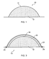
Fig. 1 is a diagrammatic cross-section of a tool according to various embodiments of the present invention; -
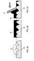
Fig. 2A, 2B and 2C illustrate a diagrammatic cross section view of a tool body according to various embodiments of the present invention receiving a sealant; -
Fig. 3 is a diagrammatic cross-section of the tool ofFig. 1 in use in forming a moulded article in accordance with the present invention; -
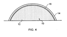
Fig. 4 is a diagrammatic cross-section of the tool in use in forming a moulded article in accordance with various embodiments of the present invention. - Embodiments of the present invention provide a
tool 10 for use in forming moulded articles, thetool 10 comprising atool body 12 formed of a ceramic material. - One particular application of the tools of embodiments of the present invention is in the formation or manufacture of moulded articles formed from curable, resinous composite materials. Such materials have well known advantageous properties, generally being relatively lightweight and of high strength making them useful in the manufacture of articles and components for use in many diverse industries, such as the aeronautical, motor sport, civil engineering and automotive industries, as well as in most areas of sport. Such curable composite materials are well known to those skilled in the art.
- The tooling of embodiments of the present invention and the associated methodologies find application for the moulding of many different types of composite materials, including both relatively low temperature cure and high end temperature cure materials. It is perhaps in relation to the latter where embodiments of the present invention find most advantage, as will be described.
- In more detail, the
tool body 12 comprises porous ceramic material and is preferably of a foamed structure. The ceramic material has a porosity of 40% to 60%. In various embodiments, the ceramic material may have a porosity of 45% to 55%. - The
tool body 12 may be manufactured by blending various ceramic ingredients (e.g. alumina, clay etc.) into powder form. The blended powder may then be loaded into a press tool (the un-compacted powder has a bulk factor of approximately 150%) and approximately 700,000 kgm-2 (0.5 ton/sq.in) pressure is applied (e.g. for approximately 10 seconds) to form a pressed body. In other embodiments, approximately 350,000 kg/m-2 (0.25 ton/sq.in) is applied to form a pressed body. The pressed body is then heated (e.g. in an oven) to drive off moisture to form thebody 12. - One advantage provided by the porous
ceramic body 12 is that it has a relatively low thermal mass (when compared to a non-porous body) which may reduce energy costs when the body is heated. Another advantage provided by the porousceramic body 12 is that it is relatively easy to machine to a desired shape (when compared to a non-porous body). - In various embodiments of the present invention, the
tool body 12 comprises one or more of cordierite, alumina silicate and/or derivatives thereof aluminium oxide and may include Dylite (a form of Cordierite), a porous ceramic material which is produced by Dyson Thermal Technologies. Dylite comprises approximately 42% Al2O3, approximately 49% SiO2, approximately 5.5% MgO and approximately 0.7% Fe2O3. - Where the
body 12 comprises Dylite and is formed using 700.000 kgm-2 pressure, thebody 12 has an apparent porosity of approximately 50%, a density of approximately 1100 kgm-3, a coefficient of thermal expansion of approximately 2.5 x 10⁻⁶ K-1 and a maximum temperature of use of approximately 1300°C. One advantage provided by using abody 12 which includes Dylite is that it absorbs little to no moisture in a relatively humid environment (e.g. in an environment with a relative humidity of 85%). - Where the
tool body 12 comprises Dylite and is formed using 700,000 kgm-2 pressure, thetool body 12 may have the following properties:Property Result St Dev. No. Samples Maximum Minimum Cold Crush Strength 32.9 MPa 3.0 10 36.9 27.7 Flex Modulus 2.8 GPa 0.7 10 4.0 1.7 Flex Strength 5.6 MPa 0.7 10 6.7 4.7 Thermal Conductivity 0.69 Wm-1K-1 - 4 0.75 0.65 Specific Heat 1074 JKg-1K-1 - - - Where the
tool body 12 comprises Dylite and is formed using 350,000 kgm-2 pressure, thetool body 12 may have the following properties:Property Result St Dev. No. Samples Maximum Minimum Cold Crush Strength 20.10 MPa 2.57 10 23.66 15.29 Flex Modulus 2.35 GPa 0.7 6 3.06 1.21 Flex Strength 4.46 MPa 0.62 7 5.5 3.9 - The construction of the foamed
body 12 can depend upon the scale of the tool required. Thebody 12 can be formed from a single block of material, or where large scale tools are required, a number of blocks can be bonded together to form the basic tool structure. For example, the blocks may be bonded together using a cement, a polyvinyl acetate (PVA) adhesive or using a two-pack thermoset adhesive. - The block or structure would then usually be machined or otherwise shaped to the required geometry. For example, the block or structure may be machined using a tungsten carbide tool (or any other suitable tool) at cutter speeds of 15,000 to 22,000 revolutions per minute (rpm) and fed at a rate of up to 1000 mm per minute. The
body 12 illustrated in the Figures is, in cross-section, a simple shape for ease of illustration, but it will be appreciated that such foamed bodies can be quite intrically shaped using for example, CNC machinery. Ceramic foam can be very accurately and intricately shaped in this way. - The ceramic material has a low Coefficient of Thermal Expansion of less than 10ppm/°C for use with carbon fibre moulding and desirably less than 5ppm/°C.
- The
outer surface 11 of thetool body 12 is sealed with epoxy sealant. This sealed surface could provide the mould surface of thetool 10. The sealant acts to prevent resin from material being moulded thereon from migrating into the pores of the ceramic material. -
Figures 2A, 2B and 2C illustrate how a sealant may be applied to atool body 12. InFig. 2A , atool body 12 is illustrated which comprises a surface with a plurality ofpores 13. Next (inFig. 2B ), a sealant (e.g. an epoxy sealant) is provided on the surface of thetool body 12. The sealant may be applied to the surface of thetool body 12 using a brush or by spraying. Then (inFig. 2C ), a screed 17 (e.g, a plastic spreader) is moved across the first surface of thetool body 12 to removeexcess sealant 15 from thetool body 12 and to push the sealant into thepores 13. - One advantage of the above method is that it provides an accurate, relatively smooth surface which provides a seal against resin from material being moulded thereon. Additionally, one advantage of using the
plastic spreader 17 is that it does little to no damage to the surface of thetool body 12. -
Fig. 4 shows the embodiment wherein thetool 10 has theresinous material 14 located on thebody 12, and so when thebody 12 is machined to the desired geometry, it is made slightly smaller than the required tool size to allow for the thickness of the resinous layer. The resinous layer provides the tool moulding surface. - In alternative embodiments where further layer(s) are applied over the resinous material wherein the resinous material does not provide the moulding surface of the tool, the
body 12 is machined to the appropriate size and shaped to take into account the further layers so that the tool surface is of the desired shape and size. - In a further embodiment
elastomeric material 16 is applied to the appropriate surface(s) ofbody 12. In this embodiment theelastomeric material 16 forms alayer 16 over thebody 12. - The elastomeric material comprises a fluoroelastomer, which can be applied to the
body 12 in the form of a curable film. It is however within the scope of the present invention that the elastomer is provided in other forms, such as in liquid form and may be sprayed, painted or otherwise applied. - Thickness is generally between 1.5mm (0.063in) and 0.76mm (0.031 in), although this can be adapted to suit.
- The
resinous material 14 is then laminated directly onto the surface of theelastomer film 16, so that theelastomer film 16 is located directly between thebody 12 and theresinous material 14. Theelastomer film 16 is substantially impermeable to the resin in theresinous material 14, thus acting to inhibit the transfer of resin into thebody 12. - The
resinous material 14 may be of any suitable curable material, and is applied as a layer. - One example is a layer or prepreg of epoxy resin matrix material with fibre reinforcements such as carbon or glass fibres, which require relatively low cure temperatures (between 40°C and 200°C).
- Another example is a bismaleimide matrix with fibre reinforcement, which again in this embodiment is carbon fibre. This requires relatively high cure temperature (200°C).
- It will be appreciated that other curable matrix materials known to the person skilled in the art can be used, such as other low temperature cure resins and other high temperature cure resins like cyanate esters, polyimides and thermoplastics. Blends and mixtures of known materials can be used.
- Both the elastomeric film and the
resinous layer 14 are cured in situ on thefoam body 12. Thebody 12,elastomer 16 andresinous layer 14 bond together, with little or no migration of resin from theresinous layer 14 into thefoam body 12. Theelastomer 16 therefore acts to inhibit movement of resin into thefoam body 12, both before and during cure. - This has been shown to work with both low temperature cure and high temperature cure resinous layers, and particularly for the latter this is a significant advantage due to the very low viscosities certain such resins, e.g. BMI's exhibit during cure. The elastomer has been shown to bond well between and to both the
foam body 12 and theresinous material 14. - The tool of the present application finds particular advantage in that it can be used in the moulding of both low and high temperature cure materials, since the
elastomer layer 16, the high temperature cure resinous material and theceramic body 12 can all withstand high cure temperatures. This enables the tool to be used in the moulding of articles and structures using high temperature cure resin systems. - The
elastomer layer 16 also helps prevent brittle fractures propagating between thebody 12 and theresinous layer 14. The elastomer provides a compliant layer or interface between thebody 12 and theresinous layer 14 which allows for a small degree of movement without damage, such movement being possible as a result of the differences between the coefficient of thermal expansion of thebody 12 andlayer 14, and also possible tool skin (resinous layer 14) shrinkage. - A further advantage is that the impermeable nature of the
elastomer film 16 is such that it addresses difficulties of vacuum integrity during moulding of articles on the tool, as will be explained. - The
resinous layer 14 as indicated above, can comprise one or more different types or blends of resinous material, according to the desired application of the tool. Thelayer 14 could also comprise a laminate, wherein multiple plies are provided within thelayer 14. These plies may comprise the same or different material, according to known techniques. - For example, the
layer 14 could comprise a single layer of fibre reinforced prepreg wherein the fibrous material is fully, partially, or generally not impregnated into the fibre. - The laminate may comprise one or more resinous plies laminated with one or more dry fibre layers, syntactic layers or any other layers known to those skilled in the art.
- Once the resinous material and elastomer have been cured on the
tool body 12, theouter surface 18 of the resinous layer 40 on which material is to be loaded for moulding, can be finished to provide the desired geometry and surface finish, such as by way of further machining, sanding or the like. - In other embodiments, the
tool body 12 may be sealed with a controlled-flow matrix carbon fibre reinforced plastic (CFRP) skin. The controlled-flow matrix carbon fibre reinforced plastic (CFRP) skin may be a thermoset matrix and may be, for example, an epoxy or bismaleimide matrix. In these embodiments, the resin of the CFRP skin has a relatively low rate of flow and does not substantially migrate into thetool body 12. One advantage provided by these embodiments is that due to the low rate of flow of the resin, an elastomer layer may not be required to seal thetool body 12. - The present invention also provides a method of moulding an article on a tool as described above.
- With reference to
Fig. 3 , material to be moulded 20 is laid on thesurface 18 of thetool 10. Thematerial 20 may be of any known composition and structure, but again a particular advantage of the present invention is that thetool 10 can withstand relatively high temperatures and therefore can be used effectively to manufacture moulded articles from curable resinous materials requiring relatively high cure temperatures. - Once the
material 20 has been laid on thesurface 18, it is subjected to appropriate conditions to cure thematerial 20. InFig. 2 , a conventional vacuum bag system is illustrated wherein avacuum membrane 22 is located around thematerial 20 and sealed against thebody 12 by conventional seal means 24. Details and advantages of the vacuum bagging technique will be known to those skilled in the art. - During cure, air is withdrawn from beneath the sealed
membrane 22 to facilitate consolidation and reduce the formation of voids within thematerial 20, again as will be understood by those skilled in the art. - Importantly, the substantially impermeable nature of the
elastomeric layer 16 and/or the sealant on the ceramic body surface is such that it enables the vacuum bag arrangement to be sealed, thus providing vacuum integrity, thus avoiding the difficulties of the inherent porosity of the foamedbody 12. - Various embodiments may be made without departing from the scope of the present invention.
- The elastomeric material may be applied over a plurality of discrete surfaces or surface areas on the tool body, where absorption of resin is to be inhibited.
- The elastomeric material may comprise either in addition to that described above, or as an alternative, one or more of low temperature cure silicone elastomers, butyl elastomers and/or polyurethane elastomers.
- The resinous material may comprise thermoset and/or thermoplastic resin.
Claims (16)
- A tool for use in forming moulded articles, the tool comprising a porous tool body having a porosity of 40% to 60% formed of pressed powdered ceramic material and a fibre-reinforced resinous material on the tool body which provides surface(s) of the tool on which articles can be formed.
- A tool as claimed in claim 1, in which the ceramic material comprises ceramic foam.
- A tool as claimed in any preceding claim, in which the ceramic material has a Coefficient of Thermal Expansion of less than 10ppm/°C.
- A tool as claimed in any preceding claim, in which the ceramic material has a Coefficient of Thermal Expansion of less than 5ppm/°C.
- A tool as claimed in any preceding claim, in which the tool body comprises one or more of cordierite, alumina silicate and/or derivatives thereof.
- A tool as claimed in any preceding claim, in which the tool comprises an elastomeric material located between said tool body and resinous material to inhibit the movement of resin from the resinous material into the tool body.
- A tool as claimed in any preceding claim, in which a surface of the ceramic material over which the resinous material is laid is sealed.
- A tool as claimed in any preceding claim, in which the tool body also includes one or more of thermoplastic, glass and carbon.
- A tool as claimed in any preceding claim, in which the resinous material comprises a fibre reinforced resinous material,
- A tool as claimed in any preceding claim, in which the resinous material is curable at temperatures of less than 200°C (approx).
- A tool as claimed in any of claims 1 to 9, in which the resinous material is curable at temperatures over 200°C (approx).
- A tool as claimed in any preceding claim, in which the resinous material comprises one or more of a bismaleimide, cyanate ester, polyimide and/or thermoplastic.
- A tool as claimed in any preceding claim, in which the resinous material comprises a blend of resins, some of which are cured at temperatures below 200°C, and some of which are cured at temperatures over 200°C.
- A tool as claimed in any preceding claim, in which the resinous material comprises a laminate structure comprising a plurality of plies.
- A method of manufacturing a tool for use in forming moulded articles, the method comprising forming a porous tool body of pressed powdered ceramic material, the tool body having a porosity of 40% to 60% and applying fibre-reinforced resinous material to the tool body to provide moulding surface(s).
- A method of moulding an article on a tool as defined in any of claims 1 to 14, the method comprising laying material to be moulded on to the tool and subjecting the material to conditions to mould the material thereon.
Applications Claiming Priority (3)
| Application Number | Priority Date | Filing Date | Title |
|---|---|---|---|
| GBGB0809158.9A GB0809158D0 (en) | 2008-05-20 | 2008-05-20 | Ceramic tools |
| GBGB0823498.1A GB0823498D0 (en) | 2008-05-20 | 2008-12-24 | Ceramic tools |
| PCT/GB2009/001237 WO2009141592A2 (en) | 2008-05-20 | 2009-05-19 | Ceramic tools |
Publications (2)
| Publication Number | Publication Date |
|---|---|
| EP2297067A2 EP2297067A2 (en) | 2011-03-23 |
| EP2297067B1 true EP2297067B1 (en) | 2014-08-20 |
Family
ID=39596205
Family Applications (1)
| Application Number | Title | Priority Date | Filing Date |
|---|---|---|---|
| EP09750070.6A Active EP2297067B1 (en) | 2008-05-20 | 2009-05-19 | Tool formed of pressed powdered ceramic material for use in forming moulded articles |
Country Status (5)
| Country | Link |
|---|---|
| US (1) | US9802370B2 (en) |
| EP (1) | EP2297067B1 (en) |
| ES (1) | ES2517899T3 (en) |
| GB (3) | GB0809158D0 (en) |
| WO (1) | WO2009141592A2 (en) |
Families Citing this family (4)
| Publication number | Priority date | Publication date | Assignee | Title |
|---|---|---|---|---|
| GB0622293D0 (en) * | 2006-11-09 | 2006-12-20 | Advanced Composites Group Ltd | Foamed tools |
| GB2480625A (en) * | 2010-05-25 | 2011-11-30 | Advanced Composites Group Ltd | Mould tool comprising a foamed Ferrous/Nickel alloy |
| FR2966767B1 (en) * | 2010-10-28 | 2016-04-01 | Crassous Dominique Francois Daniel | PRESS FOR THE MOLDING OF COMPOSITE MATERIALS. |
| EP2918704B1 (en) * | 2014-03-14 | 2019-08-07 | FRANZ Oberflächentechnik GmbH & Co KG | Method for conditioning a component |
Citations (1)
| Publication number | Priority date | Publication date | Assignee | Title |
|---|---|---|---|---|
| US4851280A (en) * | 1988-04-01 | 1989-07-25 | E. I. Du Pont De Nemours And Company | Composite tooling for composites manufacture |
Family Cites Families (18)
| Publication number | Priority date | Publication date | Assignee | Title |
|---|---|---|---|---|
| US2809898A (en) * | 1954-02-16 | 1957-10-15 | Gen Electric | Porous ceramic mold and method of making same |
| DD247412A1 (en) | 1986-04-01 | 1987-07-08 | Ve Wissenschaftlich Tech Betri | ASBEST-FREE HEAT INSULATION ELEMENT FOR TOOLS OF DUROPLAST PROCESSING |
| JP2512929B2 (en) | 1987-02-09 | 1996-07-03 | 東ソー株式会社 | Plastic injection mold |
| JPS6449607A (en) | 1987-08-20 | 1989-02-27 | Showa Denko Kk | Metal mold |
| JPH06184723A (en) | 1992-04-20 | 1994-07-05 | Janome Sewing Mach Co Ltd | Production of ceramic die |
| US5814161A (en) * | 1992-11-30 | 1998-09-29 | Massachusetts Institute Of Technology | Ceramic mold finishing techniques for removing powder |
| US5580666A (en) * | 1995-01-20 | 1996-12-03 | The Dow Chemical Company | Cemented ceramic article made from ultrafine solid solution powders, method of making same, and the material thereof |
| US6210612B1 (en) * | 1997-03-31 | 2001-04-03 | Pouvair Corporation | Method for the manufacture of porous ceramic articles |
| JP3548383B2 (en) | 1997-07-07 | 2004-07-28 | キヤノン株式会社 | Resin mold |
| US6174481B1 (en) * | 1998-09-10 | 2001-01-16 | Lear Automotive Dearborn, Inc. | Method for forming cast tooling for polymer molding |
| GB2346340A (en) | 1999-02-03 | 2000-08-09 | Rolls Royce Plc | A ceramic core, a disposable pattern, a method of making a disposable pattern, a method of making a ceramic shell mould and a method of casting |
| US6948695B1 (en) * | 2001-03-12 | 2005-09-27 | Knight Manufacturing Co., Inc. | Molds for casting fishing lures and other products |
| FR2846591B1 (en) * | 2002-10-30 | 2006-07-07 | Eurocopter France | DISPERSION PRODUCT FOR MOLDED PARTS IN COMPOSITE MATERIAL. |
| US20050023727A1 (en) * | 2003-04-29 | 2005-02-03 | Sampson James K. | Autoclave molding system for carbon composite materials |
| DE10335224A1 (en) * | 2003-07-30 | 2005-03-24 | Universität Bremen | Method for production of a molded body from ceramic material using metal powder and a colloidal sol useful in space shuttle-, microsystem-, fireproofing-, and/or foundry-, and/or biotechnology technology, e.g. chromatography |
| WO2007130372A2 (en) | 2006-05-01 | 2007-11-15 | American Consulting Technology & Research | Method for extending the useful life of mold type tooling |
| GB0622293D0 (en) * | 2006-11-09 | 2006-12-20 | Advanced Composites Group Ltd | Foamed tools |
| GB0623048D0 (en) * | 2006-11-18 | 2006-12-27 | Bentley Motors Ltd | Improvements in or relating to ceramic tooling |
-
2008
- 2008-05-20 GB GBGB0809158.9A patent/GB0809158D0/en not_active Ceased
- 2008-12-24 GB GBGB0823498.1A patent/GB0823498D0/en not_active Ceased
-
2009
- 2009-05-19 GB GB0908532.5A patent/GB2460162B/en active Active
- 2009-05-19 US US12/993,268 patent/US9802370B2/en active Active
- 2009-05-19 WO PCT/GB2009/001237 patent/WO2009141592A2/en active Application Filing
- 2009-05-19 ES ES09750070.6T patent/ES2517899T3/en active Active
- 2009-05-19 EP EP09750070.6A patent/EP2297067B1/en active Active
Patent Citations (1)
| Publication number | Priority date | Publication date | Assignee | Title |
|---|---|---|---|---|
| US4851280A (en) * | 1988-04-01 | 1989-07-25 | E. I. Du Pont De Nemours And Company | Composite tooling for composites manufacture |
Also Published As
| Publication number | Publication date |
|---|---|
| WO2009141592A3 (en) | 2010-04-08 |
| WO2009141592A8 (en) | 2010-02-18 |
| GB2460162A (en) | 2009-11-25 |
| EP2297067A2 (en) | 2011-03-23 |
| WO2009141592A2 (en) | 2009-11-26 |
| GB0908532D0 (en) | 2009-06-24 |
| US20110100537A1 (en) | 2011-05-05 |
| ES2517899T3 (en) | 2014-11-04 |
| US9802370B2 (en) | 2017-10-31 |
| GB0809158D0 (en) | 2008-06-25 |
| GB0823498D0 (en) | 2009-01-28 |
| GB2460162B (en) | 2013-04-17 |
Similar Documents
| Publication | Publication Date | Title |
|---|---|---|
| JP5112443B2 (en) | Foam tools | |
| JP5044220B2 (en) | Carbon foam composite tool and method for using the carbon foam composite tool | |
| EP1005978B1 (en) | Methods of forming honeycomb sandwich composite panels | |
| US4316934A (en) | Method for making laminates comprising a hard foam layer and a fiber-reinforced synthetic resin layer | |
| RU2681898C2 (en) | Method and device for producing sandwich component, and sandwich component | |
| EP2297067B1 (en) | Tool formed of pressed powdered ceramic material for use in forming moulded articles | |
| CN110843234A (en) | Forming process method of unmanned aerial vehicle carbon fiber composite main beam | |
| JP2007521987A5 (en) | ||
| EP3331681B1 (en) | Multi-sectional composite tooling | |
| WO2011142885A1 (en) | Method of making a composite sandwich structure and sandwich structure made thereby | |
| CN109532058A (en) | A kind of Varying-thickness polymer matrix composites structure preparation method | |
| CN114055806B (en) | Composite material hybrid skin forming method | |
| JPH07195376A (en) | Mold for fiber reinforced plastic, master mold and production of them | |
| US6352609B1 (en) | Composite tooling process for curing materials at elevated temperatures | |
| GB2254820A (en) | Tooling for composite component manufacture | |
| US20200262160A1 (en) | Tool and associated method for manufacturing the same | |
| CA2804892C (en) | Mould tools | |
| GB2053785A (en) | Method of manufacturing panels | |
| GB2423496A (en) | A foam body for a master model | |
| JPS62135349A (en) | Manufacture of fiber reinforced plastic | |
| CN114368170A (en) | Manufacturing method of airplane cargo bridge body | |
| JPH1110656A (en) | Manufacture of fiber-reinforced resin composite body |
Legal Events
| Date | Code | Title | Description |
|---|---|---|---|
| PUAI | Public reference made under article 153(3) epc to a published international application that has entered the european phase |
Free format text: ORIGINAL CODE: 0009012 |
|
| 17P | Request for examination filed |
Effective date: 20101207 |
|
| AK | Designated contracting states |
Kind code of ref document: A2 Designated state(s): AT BE BG CH CY CZ DE DK EE ES FI FR GB GR HR HU IE IS IT LI LT LU LV MC MK MT NL NO PL PT RO SE SI SK TR |
|
| AX | Request for extension of the european patent |
Extension state: AL BA RS |
|
| DAX | Request for extension of the european patent (deleted) | ||
| RAP1 | Party data changed (applicant data changed or rights of an application transferred) |
Owner name: UMECO STRUCTURAL MATERIALS (DERBY) LIMITED |
|
| 17Q | First examination report despatched |
Effective date: 20120817 |
|
| REG | Reference to a national code |
Ref country code: DE Ref legal event code: R079 Ref document number: 602009026145 Country of ref document: DE Free format text: PREVIOUS MAIN CLASS: C04B0035190000 Ipc: B28B0007000000 |
|
| GRAP | Despatch of communication of intention to grant a patent |
Free format text: ORIGINAL CODE: EPIDOSNIGR1 |
|
| RIC1 | Information provided on ipc code assigned before grant |
Ipc: B29C 70/06 20060101ALI20140217BHEP Ipc: B29C 33/00 20060101ALI20140217BHEP Ipc: B29C 51/36 20060101ALI20140217BHEP Ipc: B28B 7/00 20060101AFI20140217BHEP Ipc: B28B 7/36 20060101ALI20140217BHEP Ipc: B29C 70/34 20060101ALI20140217BHEP |
|
| INTG | Intention to grant announced |
Effective date: 20140320 |
|
| GRAS | Grant fee paid |
Free format text: ORIGINAL CODE: EPIDOSNIGR3 |
|
| GRAA | (expected) grant |
Free format text: ORIGINAL CODE: 0009210 |
|
| AK | Designated contracting states |
Kind code of ref document: B1 Designated state(s): AT BE BG CH CY CZ DE DK EE ES FI FR GB GR HR HU IE IS IT LI LT LU LV MC MK MT NL NO PL PT RO SE SI SK TR |
|
| REG | Reference to a national code |
Ref country code: GB Ref legal event code: FG4D |
|
| REG | Reference to a national code |
Ref country code: CH Ref legal event code: EP |
|
| REG | Reference to a national code |
Ref country code: AT Ref legal event code: REF Ref document number: 683192 Country of ref document: AT Kind code of ref document: T Effective date: 20140915 |
|
| REG | Reference to a national code |
Ref country code: IE Ref legal event code: FG4D |
|
| REG | Reference to a national code |
Ref country code: DE Ref legal event code: R096 Ref document number: 602009026145 Country of ref document: DE Effective date: 20141002 |
|
| REG | Reference to a national code |
Ref country code: ES Ref legal event code: FG2A Ref document number: 2517899 Country of ref document: ES Kind code of ref document: T3 Effective date: 20141104 |
|
| REG | Reference to a national code |
Ref country code: NL Ref legal event code: T3 |
|
| REG | Reference to a national code |
Ref country code: LT Ref legal event code: MG4D |
|
| PG25 | Lapsed in a contracting state [announced via postgrant information from national office to epo] |
Ref country code: FI Free format text: LAPSE BECAUSE OF FAILURE TO SUBMIT A TRANSLATION OF THE DESCRIPTION OR TO PAY THE FEE WITHIN THE PRESCRIBED TIME-LIMIT Effective date: 20140820 Ref country code: GR Free format text: LAPSE BECAUSE OF FAILURE TO SUBMIT A TRANSLATION OF THE DESCRIPTION OR TO PAY THE FEE WITHIN THE PRESCRIBED TIME-LIMIT Effective date: 20141121 Ref country code: LT Free format text: LAPSE BECAUSE OF FAILURE TO SUBMIT A TRANSLATION OF THE DESCRIPTION OR TO PAY THE FEE WITHIN THE PRESCRIBED TIME-LIMIT Effective date: 20140820 Ref country code: SE Free format text: LAPSE BECAUSE OF FAILURE TO SUBMIT A TRANSLATION OF THE DESCRIPTION OR TO PAY THE FEE WITHIN THE PRESCRIBED TIME-LIMIT Effective date: 20140820 Ref country code: PT Free format text: LAPSE BECAUSE OF FAILURE TO SUBMIT A TRANSLATION OF THE DESCRIPTION OR TO PAY THE FEE WITHIN THE PRESCRIBED TIME-LIMIT Effective date: 20141222 Ref country code: NO Free format text: LAPSE BECAUSE OF FAILURE TO SUBMIT A TRANSLATION OF THE DESCRIPTION OR TO PAY THE FEE WITHIN THE PRESCRIBED TIME-LIMIT Effective date: 20141120 Ref country code: BG Free format text: LAPSE BECAUSE OF FAILURE TO SUBMIT A TRANSLATION OF THE DESCRIPTION OR TO PAY THE FEE WITHIN THE PRESCRIBED TIME-LIMIT Effective date: 20141120 |
|
| PG25 | Lapsed in a contracting state [announced via postgrant information from national office to epo] |
Ref country code: LV Free format text: LAPSE BECAUSE OF FAILURE TO SUBMIT A TRANSLATION OF THE DESCRIPTION OR TO PAY THE FEE WITHIN THE PRESCRIBED TIME-LIMIT Effective date: 20140820 Ref country code: IS Free format text: LAPSE BECAUSE OF FAILURE TO SUBMIT A TRANSLATION OF THE DESCRIPTION OR TO PAY THE FEE WITHIN THE PRESCRIBED TIME-LIMIT Effective date: 20141220 Ref country code: HR Free format text: LAPSE BECAUSE OF FAILURE TO SUBMIT A TRANSLATION OF THE DESCRIPTION OR TO PAY THE FEE WITHIN THE PRESCRIBED TIME-LIMIT Effective date: 20140820 |
|
| PG25 | Lapsed in a contracting state [announced via postgrant information from national office to epo] |
Ref country code: SK Free format text: LAPSE BECAUSE OF FAILURE TO SUBMIT A TRANSLATION OF THE DESCRIPTION OR TO PAY THE FEE WITHIN THE PRESCRIBED TIME-LIMIT Effective date: 20140820 Ref country code: CZ Free format text: LAPSE BECAUSE OF FAILURE TO SUBMIT A TRANSLATION OF THE DESCRIPTION OR TO PAY THE FEE WITHIN THE PRESCRIBED TIME-LIMIT Effective date: 20140820 Ref country code: RO Free format text: LAPSE BECAUSE OF FAILURE TO SUBMIT A TRANSLATION OF THE DESCRIPTION OR TO PAY THE FEE WITHIN THE PRESCRIBED TIME-LIMIT Effective date: 20140820 Ref country code: EE Free format text: LAPSE BECAUSE OF FAILURE TO SUBMIT A TRANSLATION OF THE DESCRIPTION OR TO PAY THE FEE WITHIN THE PRESCRIBED TIME-LIMIT Effective date: 20140820 Ref country code: DK Free format text: LAPSE BECAUSE OF FAILURE TO SUBMIT A TRANSLATION OF THE DESCRIPTION OR TO PAY THE FEE WITHIN THE PRESCRIBED TIME-LIMIT Effective date: 20140820 |
|
| REG | Reference to a national code |
Ref country code: DE Ref legal event code: R097 Ref document number: 602009026145 Country of ref document: DE |
|
| PG25 | Lapsed in a contracting state [announced via postgrant information from national office to epo] |
Ref country code: PL Free format text: LAPSE BECAUSE OF FAILURE TO SUBMIT A TRANSLATION OF THE DESCRIPTION OR TO PAY THE FEE WITHIN THE PRESCRIBED TIME-LIMIT Effective date: 20140820 |
|
| PLBE | No opposition filed within time limit |
Free format text: ORIGINAL CODE: 0009261 |
|
| STAA | Information on the status of an ep patent application or granted ep patent |
Free format text: STATUS: NO OPPOSITION FILED WITHIN TIME LIMIT |
|
| 26N | No opposition filed |
Effective date: 20150521 |
|
| PG25 | Lapsed in a contracting state [announced via postgrant information from national office to epo] |
Ref country code: SI Free format text: LAPSE BECAUSE OF FAILURE TO SUBMIT A TRANSLATION OF THE DESCRIPTION OR TO PAY THE FEE WITHIN THE PRESCRIBED TIME-LIMIT Effective date: 20140820 |
|
| REG | Reference to a national code |
Ref country code: CH Ref legal event code: PL |
|
| PG25 | Lapsed in a contracting state [announced via postgrant information from national office to epo] |
Ref country code: LI Free format text: LAPSE BECAUSE OF NON-PAYMENT OF DUE FEES Effective date: 20150531 Ref country code: MC Free format text: LAPSE BECAUSE OF FAILURE TO SUBMIT A TRANSLATION OF THE DESCRIPTION OR TO PAY THE FEE WITHIN THE PRESCRIBED TIME-LIMIT Effective date: 20140820 Ref country code: CH Free format text: LAPSE BECAUSE OF NON-PAYMENT OF DUE FEES Effective date: 20150531 |
|
| REG | Reference to a national code |
Ref country code: FR Ref legal event code: PLFP Year of fee payment: 8 |
|
| PG25 | Lapsed in a contracting state [announced via postgrant information from national office to epo] |
Ref country code: MT Free format text: LAPSE BECAUSE OF FAILURE TO SUBMIT A TRANSLATION OF THE DESCRIPTION OR TO PAY THE FEE WITHIN THE PRESCRIBED TIME-LIMIT Effective date: 20140820 |
|
| REG | Reference to a national code |
Ref country code: FR Ref legal event code: PLFP Year of fee payment: 9 |
|
| PG25 | Lapsed in a contracting state [announced via postgrant information from national office to epo] |
Ref country code: HU Free format text: LAPSE BECAUSE OF FAILURE TO SUBMIT A TRANSLATION OF THE DESCRIPTION OR TO PAY THE FEE WITHIN THE PRESCRIBED TIME-LIMIT; INVALID AB INITIO Effective date: 20090519 |
|
| PG25 | Lapsed in a contracting state [announced via postgrant information from national office to epo] |
Ref country code: CY Free format text: LAPSE BECAUSE OF FAILURE TO SUBMIT A TRANSLATION OF THE DESCRIPTION OR TO PAY THE FEE WITHIN THE PRESCRIBED TIME-LIMIT Effective date: 20140820 |
|
| PG25 | Lapsed in a contracting state [announced via postgrant information from national office to epo] |
Ref country code: TR Free format text: LAPSE BECAUSE OF FAILURE TO SUBMIT A TRANSLATION OF THE DESCRIPTION OR TO PAY THE FEE WITHIN THE PRESCRIBED TIME-LIMIT Effective date: 20140820 |
|
| REG | Reference to a national code |
Ref country code: FR Ref legal event code: PLFP Year of fee payment: 10 |
|
| PG25 | Lapsed in a contracting state [announced via postgrant information from national office to epo] |
Ref country code: MK Free format text: LAPSE BECAUSE OF FAILURE TO SUBMIT A TRANSLATION OF THE DESCRIPTION OR TO PAY THE FEE WITHIN THE PRESCRIBED TIME-LIMIT Effective date: 20140820 |
|
| REG | Reference to a national code |
Ref country code: LU Ref legal event code: HC Owner name: CYTEC INDUSTRIAL MATERIALS (DERBY) LIMITED; GB Free format text: FORMER OWNER: UMECO STRUCTURAL MATERIALS (DERBY) LIMITED Effective date: 20210217 Ref country code: LU Ref legal event code: PD Owner name: CYTEC PROCESS MATERIALS (CA) INC; US Free format text: FORMER OWNER: CYTEC INDUSTRIAL MATERIALS (DERBY) LIMITED Effective date: 20210217 |
|
| REG | Reference to a national code |
Ref country code: ES Ref legal event code: PC2A Owner name: CYTEC PROCESS MATERIALS (CA) INC. Effective date: 20210323 |
|
| REG | Reference to a national code |
Ref country code: DE Ref legal event code: R082 Ref document number: 602009026145 Country of ref document: DE Ref country code: DE Ref legal event code: R081 Ref document number: 602009026145 Country of ref document: DE Owner name: CYTEC PROCESS MATERIALS (CA) INC., WILMINGTON, US Free format text: FORMER OWNER: UMECO STRUCTURAL MATERIALS (DERBY) LTD., HEANOR, DERBYSHIRE, GB |
|
| REG | Reference to a national code |
Ref country code: BE Ref legal event code: HC Owner name: CYTEC INDUSTRIAL MATERIALS (DERBY) LIMITED; GB Free format text: DETAILS ASSIGNMENT: CHANGE OF OWNER(S), CHANGE OF OWNER(S) NAME; FORMER OWNER NAME: UMECO STRUCTURAL MATERIALS (DERBY) LIMITED Effective date: 20210223 Ref country code: BE Ref legal event code: PD Owner name: CYTEC PROCESS MATERIALS (CA) INC.; US Free format text: DETAILS ASSIGNMENT: CHANGE OF OWNER(S), ASSIGNMENT; FORMER OWNER NAME: CYTEC INDUSTRIAL MATERIALS (DERBY) LIMITED Effective date: 20210223 |
|
| REG | Reference to a national code |
Ref country code: NL Ref legal event code: HC Owner name: CYTEC INDUSTRIAL MATERIALS (DERBY) LIMITED; GB Free format text: DETAILS ASSIGNMENT: CHANGE OF OWNER(S), CHANGE OF OWNER(S) NAME; FORMER OWNER NAME: UMECO STRUCTURAL MATERIALS (DERBY) LIMITED Effective date: 20210517 Ref country code: NL Ref legal event code: PD Owner name: CYTEC PROCESS MATERIALS (CA) INC.; US Free format text: DETAILS ASSIGNMENT: CHANGE OF OWNER(S), ASSIGNMENT; FORMER OWNER NAME: CYTEC INDUSTRIAL MATERIALS (DERBY) LIMITED Effective date: 20210517 |
|
| REG | Reference to a national code |
Ref country code: AT Ref legal event code: PC Ref document number: 683192 Country of ref document: AT Kind code of ref document: T Owner name: CYTEC PROCESS MATERIALS (CA) INC, US Effective date: 20210607 |
|
| REG | Reference to a national code |
Ref country code: GB Ref legal event code: 732E Free format text: REGISTERED BETWEEN 20210701 AND 20210707 |
|
| PGFP | Annual fee paid to national office [announced via postgrant information from national office to epo] |
Ref country code: IE Payment date: 20230310 Year of fee payment: 15 Ref country code: FR Payment date: 20230309 Year of fee payment: 15 |
|
| PGFP | Annual fee paid to national office [announced via postgrant information from national office to epo] |
Ref country code: GB Payment date: 20230330 Year of fee payment: 15 |
|
| PGFP | Annual fee paid to national office [announced via postgrant information from national office to epo] |
Ref country code: NL Payment date: 20230417 Year of fee payment: 15 Ref country code: LU Payment date: 20230512 Year of fee payment: 15 |
|
| PGFP | Annual fee paid to national office [announced via postgrant information from national office to epo] |
Ref country code: IT Payment date: 20230412 Year of fee payment: 15 Ref country code: ES Payment date: 20230605 Year of fee payment: 15 Ref country code: DE Payment date: 20230321 Year of fee payment: 15 |
|
| PGFP | Annual fee paid to national office [announced via postgrant information from national office to epo] |
Ref country code: AT Payment date: 20230425 Year of fee payment: 15 |
|
| PGFP | Annual fee paid to national office [announced via postgrant information from national office to epo] |
Ref country code: BE Payment date: 20230418 Year of fee payment: 15 |
|
| PGFP | Annual fee paid to national office [announced via postgrant information from national office to epo] |
Ref country code: IE Payment date: 20240312 Year of fee payment: 16 |