EP2301331A1 - Cleaning device for cleaning inside of water tank - Google Patents
Cleaning device for cleaning inside of water tank Download PDFInfo
- Publication number
- EP2301331A1 EP2301331A1 EP09804849A EP09804849A EP2301331A1 EP 2301331 A1 EP2301331 A1 EP 2301331A1 EP 09804849 A EP09804849 A EP 09804849A EP 09804849 A EP09804849 A EP 09804849A EP 2301331 A1 EP2301331 A1 EP 2301331A1
- Authority
- EP
- European Patent Office
- Prior art keywords
- water
- suction pipe
- way valve
- main body
- suction
- Prior art date
- Legal status (The legal status is an assumption and is not a legal conclusion. Google has not performed a legal analysis and makes no representation as to the accuracy of the status listed.)
- Granted
Links
- XLYOFNOQVPJJNP-UHFFFAOYSA-N water Substances O XLYOFNOQVPJJNP-UHFFFAOYSA-N 0.000 title claims abstract description 134
- 238000004140 cleaning Methods 0.000 title description 3
- 239000002699 waste material Substances 0.000 abstract description 13
- 238000003825 pressing Methods 0.000 abstract description 4
- 241000251468 Actinopterygii Species 0.000 description 12
- 238000009395 breeding Methods 0.000 description 3
- 230000001488 breeding effect Effects 0.000 description 3
- 238000011144 upstream manufacturing Methods 0.000 description 3
- 230000000694 effects Effects 0.000 description 2
- 239000010419 fine particle Substances 0.000 description 2
- 238000000034 method Methods 0.000 description 2
- 238000005086 pumping Methods 0.000 description 2
- 230000000384 rearing effect Effects 0.000 description 2
- 241000252229 Carassius auratus Species 0.000 description 1
- BZHJMEDXRYGGRV-UHFFFAOYSA-N Vinyl chloride Chemical compound ClC=C BZHJMEDXRYGGRV-UHFFFAOYSA-N 0.000 description 1
- 230000007423 decrease Effects 0.000 description 1
- 238000010586 diagram Methods 0.000 description 1
- 238000001914 filtration Methods 0.000 description 1
- 239000000463 material Substances 0.000 description 1
- 238000011084 recovery Methods 0.000 description 1
- 229920003002 synthetic resin Polymers 0.000 description 1
- 239000000057 synthetic resin Substances 0.000 description 1
- 239000002351 wastewater Substances 0.000 description 1
Images


Classifications
-
- A—HUMAN NECESSITIES
- A01—AGRICULTURE; FORESTRY; ANIMAL HUSBANDRY; HUNTING; TRAPPING; FISHING
- A01K—ANIMAL HUSBANDRY; CARE OF BIRDS, FISHES, INSECTS; FISHING; REARING OR BREEDING ANIMALS, NOT OTHERWISE PROVIDED FOR; NEW BREEDS OF ANIMALS
- A01K63/00—Receptacles for live fish, e.g. aquaria; Terraria
- A01K63/04—Arrangements for treating water specially adapted to receptacles for live fish
-
- F—MECHANICAL ENGINEERING; LIGHTING; HEATING; WEAPONS; BLASTING
- F04—POSITIVE - DISPLACEMENT MACHINES FOR LIQUIDS; PUMPS FOR LIQUIDS OR ELASTIC FLUIDS
- F04F—PUMPING OF FLUID BY DIRECT CONTACT OF ANOTHER FLUID OR BY USING INERTIA OF FLUID TO BE PUMPED; SIPHONS
- F04F10/00—Siphons
-
- A—HUMAN NECESSITIES
- A01—AGRICULTURE; FORESTRY; ANIMAL HUSBANDRY; HUNTING; TRAPPING; FISHING
- A01K—ANIMAL HUSBANDRY; CARE OF BIRDS, FISHES, INSECTS; FISHING; REARING OR BREEDING ANIMALS, NOT OTHERWISE PROVIDED FOR; NEW BREEDS OF ANIMALS
- A01K63/00—Receptacles for live fish, e.g. aquaria; Terraria
- A01K63/10—Cleaning bottoms or walls of ponds or receptacles
-
- B—PERFORMING OPERATIONS; TRANSPORTING
- B08—CLEANING
- B08B—CLEANING IN GENERAL; PREVENTION OF FOULING IN GENERAL
- B08B9/00—Cleaning hollow articles by methods or apparatus specially adapted thereto
- B08B9/08—Cleaning containers, e.g. tanks
-
- Y—GENERAL TAGGING OF NEW TECHNOLOGICAL DEVELOPMENTS; GENERAL TAGGING OF CROSS-SECTIONAL TECHNOLOGIES SPANNING OVER SEVERAL SECTIONS OF THE IPC; TECHNICAL SUBJECTS COVERED BY FORMER USPC CROSS-REFERENCE ART COLLECTIONS [XRACs] AND DIGESTS
- Y10—TECHNICAL SUBJECTS COVERED BY FORMER USPC
- Y10T—TECHNICAL SUBJECTS COVERED BY FORMER US CLASSIFICATION
- Y10T137/00—Fluid handling
- Y10T137/2713—Siphons
- Y10T137/272—Plural
- Y10T137/2747—Main siphon with auxiliary starting, stopping or resetting siphon
-
- Y—GENERAL TAGGING OF NEW TECHNOLOGICAL DEVELOPMENTS; GENERAL TAGGING OF CROSS-SECTIONAL TECHNOLOGIES SPANNING OVER SEVERAL SECTIONS OF THE IPC; TECHNICAL SUBJECTS COVERED BY FORMER USPC CROSS-REFERENCE ART COLLECTIONS [XRACs] AND DIGESTS
- Y10—TECHNICAL SUBJECTS COVERED BY FORMER USPC
- Y10T—TECHNICAL SUBJECTS COVERED BY FORMER US CLASSIFICATION
- Y10T137/00—Fluid handling
- Y10T137/2713—Siphons
- Y10T137/2829—With strainer, filter, separator or sediment trap
-
- Y—GENERAL TAGGING OF NEW TECHNOLOGICAL DEVELOPMENTS; GENERAL TAGGING OF CROSS-SECTIONAL TECHNOLOGIES SPANNING OVER SEVERAL SECTIONS OF THE IPC; TECHNICAL SUBJECTS COVERED BY FORMER USPC CROSS-REFERENCE ART COLLECTIONS [XRACs] AND DIGESTS
- Y10—TECHNICAL SUBJECTS COVERED BY FORMER USPC
- Y10T—TECHNICAL SUBJECTS COVERED BY FORMER US CLASSIFICATION
- Y10T137/00—Fluid handling
- Y10T137/2713—Siphons
- Y10T137/2842—With flow starting, stopping or maintaining means
- Y10T137/2877—Pump or liquid displacement device for flow passage
- Y10T137/2883—Piston
-
- Y—GENERAL TAGGING OF NEW TECHNOLOGICAL DEVELOPMENTS; GENERAL TAGGING OF CROSS-SECTIONAL TECHNOLOGIES SPANNING OVER SEVERAL SECTIONS OF THE IPC; TECHNICAL SUBJECTS COVERED BY FORMER USPC CROSS-REFERENCE ART COLLECTIONS [XRACs] AND DIGESTS
- Y10—TECHNICAL SUBJECTS COVERED BY FORMER USPC
- Y10T—TECHNICAL SUBJECTS COVERED BY FORMER US CLASSIFICATION
- Y10T137/00—Fluid handling
- Y10T137/8593—Systems
- Y10T137/85978—With pump
- Y10T137/85986—Pumped fluid control
- Y10T137/86002—Fluid pressure responsive
- Y10T137/86019—Direct response valve
-
- Y—GENERAL TAGGING OF NEW TECHNOLOGICAL DEVELOPMENTS; GENERAL TAGGING OF CROSS-SECTIONAL TECHNOLOGIES SPANNING OVER SEVERAL SECTIONS OF THE IPC; TECHNICAL SUBJECTS COVERED BY FORMER USPC CROSS-REFERENCE ART COLLECTIONS [XRACs] AND DIGESTS
- Y10—TECHNICAL SUBJECTS COVERED BY FORMER USPC
- Y10T—TECHNICAL SUBJECTS COVERED BY FORMER US CLASSIFICATION
- Y10T137/00—Fluid handling
- Y10T137/8593—Systems
- Y10T137/85978—With pump
- Y10T137/86099—Hand pump
Definitions
- the present invention relates to an improvement of a cleaner for the inside of a water tank in which water-tank water inside a water tank for breeding aquarium fish, in particular dirty water-tank water in a bottom part inside the water tank, can be sucked up and drained outside the water tank.
- the water tank is provided with an internal or external filter device equipped with an air pump or a submersible pump, and water-tank water inside the water tank is filtered by forcibly circulating it to the filter device by driving the pump, but since it is impossible to obtain water quality that is necessary and sufficient for breeding and rearing aquarium fish just by filtration with such a filter device, it is necessary to regularly change water-tank water inside the water tank.
- a cleaner for the inside of a water tank in which water is changed by sucking up water-tank water together with waste material such as fish excrement or leftover food is conventionally known (ref. e.g. Patent Publication 1 below).
- this conventional cleaner has the problem that when water is sucked into the suction pipe by utilizing a siphoning action, it is necessary for an operator to put the suction pipe into water-tank water of the water tank by gripping it and then carry out a repeated operation of vertical movement of the suction pipe in its longitudinal direction; this operation is not only cumbersome, but it also requires experience, and it is difficult for a child to carry out the operation.
- the present invention has been accomplished in the light of such circumstances, and it is an object thereof to provide a novel cleaner for the inside of a water tank in which the above-mentioned operation is not required, and water can be sucked up very simply and easily even by a child by applying a siphoning action to a suction pipe.
- a cleaner for the inside of a water tank in which water-tank water within a water tank is sucked up by a siphoning action and drained outside the water tank, the cleaner comprising a suction pipe formed from a linear main body portion and a grip portion bendingly connected to the main body portion, a flexible water-guiding pipe connected to the outer end of the suction pipe, an upstream-side one-way valve provided at an appropriate place within the main body portion and only permitting the flow of water from the suction pipe to the water-guiding pipe, a downstream-side one-way valve provided within the grip portion and only permitting the flow of water from the suction pipe to the water-guiding pipe, and a suction operation tool provided in a bent connecting part between the main body portion and the grip portion and pressurizing or depressurizing the interior of a water passage between the upstream-side one-way valve and the downstream-side one-way valve.
- the suction operation tool is formed from an operation tube connected so as to communicate with the interior of the water passage and provided substantially parallel to the main body portion, a press button slidably fitted into the operation tube via a seal ring and having an outer end thereof projecting outside the operation tube, and a return spring provided within the operation tube and urging the press button toward the outside.
- a cleaner for the inside of a water tank in which water-tank water within a water tank is sucked up by a siphoning action and drained outside the water tank
- the cleaner comprising a suction pipe formed from a linear main body portion and a grip portion bendingly connected to the main body portion, a flexible water-guiding pipe connected to the outer end of the suction pipe, an upstream-side one-way valve provided at an appropriate place within the main body portion and only permitting the flow of water from the suction pipe to the water-guiding pipe, a downstream-side one-way valve provided within the grip portion and only permitting the flow of water from the suction pipe to the water-guiding pipe, and a suction operation tool provided above the suction pipe and pressurizing or depressurizing the interior of a water passage between the upstream-side one-way valve and the downstream-side one-way valve, the suction operation tool being formed from an operation tube provided above an upper wall of the suction
- the suction operation tool since the suction operation tool is connected so as to communicate with the interior of the water passage and is provided substantially parallel to the main body portion of the suction pipe, the operational direction of the suction operation tool coincides with the direction of suction of water by the suction pipe, and the operation of cleaning waste material such as leftover food or fish excrement can be carried out quickly and efficiently.
- the suction operation tool is provided above the upper wall of the suction pipe, and the operation chamber thereof is positioned above the water passage within the suction pipe, fine foreign matter such as gravel that is sucked up together with the water-tank water within the suction pipe does not enter the interior of the operation chamber of the suction operation tool and bite into the seal ring, and smooth operation of the suction operation tool can be guaranteed.
- FIGS. 1 to 6 A first embodiment of the present invention is now explained by reference to FIGS. 1 to 6 .
- a suction pipe P forming a main body part of a cleaner for the inside of a water tank is made with a transparent rigid synthetic resin material, and is formed in a dog-leg shape when viewed from the side from a straight cylindrical main body portion 1 that has an open extremity and is formed with a length that reaches to the bottom of a water tank V from the outside of the water tank V and a grip portion 2 bent so as to be communicatingly connected to the base end, that is, the downstream end, of the main body portion 1.
- the grip portion 2 is formed by removably and watertightly connecting an elbow pipe 2A and a straight pipe 2B.
- An angle formed by a central line L1 of the main body portion 1 and a central line L2 of the grip portion 2 is an obtuse angle, that is, about 105°, and this makes it difficult for the grip portion 2 to abut against an edge of the water tank V when the cleaner for the inside of a water tank is used, thus improving the operability.
- a frustoconical strainer S having a large number of slits 3 made therein is provided in the interior of a part where the main body portion 1 and the grip portion 2 of the suction pipe P are connected, and this strainer S permits the free passage of dirty water contaminated by fine waste material such as leftover food or fish excrement but prevents the passage of coarse waste material such as dead leaves or stones.
- An upstream-side one-way valve Vu is provided at the rear end, that is, an exit 4, of the strainer S.
- This upstream-side one-way valve Vu is formed from a valve hole 5 communicating with the exit 4 of the strainer S, and a valve body 6 that is connected by a hinge 7 to one side of the valve hole 5 so as to open and close the valve hole 5, and operates so as to permit the flow of water that has been sucked into the suction pipe P and passed through the strainer S but prevent the backflow thereof.
- a downstream-side one-way valve Vd is provided within a downstream side section of the suction pipe P, which is on the downstream side relative to the upstream-side one-way valve Vu, that is, within an intermediate section of the grip portion 2.
- This downstream-side one-way valve Vd is fixed within the grip portion 2 and is formed from a valve seat body 9 having a valve hole 10 opening therein, and a valve body 11 that is connected by a hinge 12 to the valve seat body 9 so as to open and close the valve hole 10.
- the valve hole 10 is formed in an elliptical shape by obliquely cutting a cylindrical body, the valve body 11 for opening and closing the valve hole 10 is also formed in an elliptical shape and connected by the hinge 12 to an upper part side of the valve seat body 9 (when the cleaner is in use), and opening and closing of the downstream-side one-way valve Vd are thereby carried out smoothly by means of the hydraulic pressure of water flowing within the suction pipe P.
- connection pipe 15 is integrally connected to the interior of the downstream end of the grip portion 2, and this connection pipe 15 is connected to the upstream end of a water-guiding pipe 17.
- the water-guiding pipe 17 is formed from a flexible transparent pipe such as a vinyl chloride pipe.
- the water-guiding pipe 17 is formed in a length that enables the downstream end of the water-guiding pipe 17 to reach beneath the water level of the water tank V when the extremity of the suction pipe P faces the bottom part within the water tank V, that is, a length that can give a siphoning action for the cleaner, which is described later.
- a suction operation tool A for sucking water into the suction pipe P is provided in a bent connecting part thereof.
- This suction operation tool A is formed from a cylindrical operation tube 20 that is provided integrally with the bent connecting part of the main body portion 1 and the grip portion 2, is provided parallel to the main body portion 1, and has an operation chamber 25 formed in the interior thereof, a press button 21 that is slidably fitted, via a seal ring 22, into the operation chamber 25 from the outer end of the opening of the operation tube 20, and a return spring 23, which is a coil spring provided in a compressed state between the inner end of the press button 21 and the base end of the operation tube 20 within the operation tube 20 and urging the press button 21 so that it projects outside, a guide rod 21a fixed to the inner end of the press button 21 slidably extending through an inner end wall 20a of the operation tube 20.
- the interior of the operation chamber 25 of the operation tube 20 communicates with a water passage 24 between the upstream-side and downstream-side one-way valves Vu and Vd within the suction pipe P, and a press face 21 p is formed at the outer end of the press button 21.
- the press button 21 compresses the return spring 23 and moves inward within the operation chamber 25 so as to pressurize the water passage 24, thus closing the upstream-side one-way valve Vu and opening the downstream-side one-way valve Vd.
- the press button 21 is moved outward by the resilient force of the return spring 23 and returns to its original position (the position in FIG. 2 ), and the water passage 24 is depressurized, thereby opening the upstream-side one-way valve Vu and closing the downstream-side one-way valve Vd at the same time.
- the dirty water from which coarse waste material such as dead leaves has been separated and removed by the strainer S does not clog the upstream-side and downstream-side one-way valves Vu and Vd with waste material, and water can be smoothly sucked up and drained continuously.
- the operation tube 20 is provided substantially parallel to the main body portion 1 of the suction pipe P, the operational direction of the suction operation tool A coincides with the suction direction of water, it becomes easy to capture waste material in the bottom part of the water tank V, and this can be sucked up and drained together with dirty water quickly and efficiently.
- FIGS. 7 and 8 A second embodiment of the present invention is now explained by reference to FIGS. 7 and 8 .
- the second embodiment is different from the fist embodiment in terms of the position at which a suction operation tool A is mounted on a suction pipe P, as shown in FIG. 7 , the suction operation tool A being provided in an upper part of the suction pipe P, that is, an upper wall of a grip portion 2.
- This suction operation tool A has the same structure as that of the first embodiment; an operation tube 20 is formed integrally with an upper face of the grip portion 2, this operation tube 20 extends upward substantially parallel to the main body portion 1, and an operation chamber 25 within the operation tube 20 is at a position outside and above a water passage 24 within the suction pipe P and communicates with the water passage 24.
- a press button 21 is slidably fitted via a seal ring 22 into the operation tube 20 from the open upper end thereof, and a press face 21p is formed on an upper face of the press button 21.
- a fingerhold piece 30 is formed integrally so as to straddle the base of the operation tube 20 on the main body portion 1 side and the upper face of the grip portion 2, and an arc-shaped fingerhold recess 31 for an operator to rest a finger on is formed on an edge part of the fingerhold portion 30. Furthermore, a hanging hole 32 is opened in the fingerhold piece 30. When the cleaner is not in use, it may be hung down from an appropriate hanger by utilizing the hanging hole 32.
- the suction operation tool A is at a position above the suction pipe P, and the operation chamber 25 is at a position outside the water passage 24 of the suction pipe P, in the suction pipe P, even if dirty water and fine foreign matter are sucked into the suction pipe P, there is no possibility of the foreign matter entering the operation chamber 25 and being caught between the seal ring 22 and the operation tube 20, and it is possible to guarantee smooth and appropriate operation of the suction operation tool A.
- This modified example is a case in which a suction operation tool A having the same structure as that of the second embodiment is provided at the upper end of a linear main body portion 1 of a suction pipe P; an operation chamber 25 is at a position outside and above a water passage 24 of the suction pipe P, and the same operation and effects as those of the second embodiment can be exhibited.
Abstract
Description
- The present invention relates to an improvement of a cleaner for the inside of a water tank in which water-tank water inside a water tank for breeding aquarium fish, in particular dirty water-tank water in a bottom part inside the water tank, can be sucked up and drained outside the water tank.
- Conventionally, when breeding and rearing aquarium fish such as goldfish, tropical fish, or marine fish inside a water tank, the water tank is provided with an internal or external filter device equipped with an air pump or a submersible pump, and water-tank water inside the water tank is filtered by forcibly circulating it to the filter device by driving the pump, but since it is impossible to obtain water quality that is necessary and sufficient for breeding and rearing aquarium fish just by filtration with such a filter device, it is necessary to regularly change water-tank water inside the water tank. A cleaner for the inside of a water tank in which water is changed by sucking up water-tank water together with waste material such as fish excrement or leftover food is conventionally known (ref. e.g. Patent Publication 1 below).
- Patent Publication 1: Japanese Patent Application Laid-open No.
2000-209978 - In the arrangement of Patent Publication 1 above, water-tank water inside the water tank is sucked outside together with waste material such as settled fish excrement or leftover food by means of a suction pipe utilizing a siphoning action; the suction pipe has a linear main body portion having open extremity and a grip portion bendingly connected to the base of the main body portion, and the suction pipe is provided with two one-way valves permitting the flow of water in one direction from the upstream side to the downstream side. This cleaner is arranged so as to efficiently suck up and drain to the outside water-tank water inside the water tank, in particular waste material such as fish excrement or leftover food, which has settled in a bottom part thereof, together with water-tank water.
- However, this conventional cleaner has the problem that when water is sucked into the suction pipe by utilizing a siphoning action, it is necessary for an operator to put the suction pipe into water-tank water of the water tank by gripping it and then carry out a repeated operation of vertical movement of the suction pipe in its longitudinal direction; this operation is not only cumbersome, but it also requires experience, and it is difficult for a child to carry out the operation.
- The present invention has been accomplished in the light of such circumstances, and it is an object thereof to provide a novel cleaner for the inside of a water tank in which the above-mentioned operation is not required, and water can be sucked up very simply and easily even by a child by applying a siphoning action to a suction pipe.
- In order to attain the above object, according to a first aspect of the present invention, there is provided a cleaner for the inside of a water tank in which water-tank water within a water tank is sucked up by a siphoning action and drained outside the water tank, the cleaner comprising
a suction pipe formed from a linear main body portion and a grip portion bendingly connected to the main body portion, a flexible water-guiding pipe connected to the outer end of the suction pipe, an upstream-side one-way valve provided at an appropriate place within the main body portion and only permitting the flow of water from the suction pipe to the water-guiding pipe, a downstream-side one-way valve provided within the grip portion and only permitting the flow of water from the suction pipe to the water-guiding pipe, and a suction operation tool provided in a bent connecting part between the main body portion and the grip portion and pressurizing or depressurizing the interior of a water passage between the upstream-side one-way valve and the downstream-side one-way valve. - In order to attain the above object, according to a second aspect of the present invention, in addition to the first aspect, the suction operation tool is formed from an operation tube connected so as to communicate with the interior of the water passage and provided substantially parallel to the main body portion, a press button slidably fitted into the operation tube via a seal ring and having an outer end thereof projecting outside the operation tube, and a return spring provided within the operation tube and urging the press button toward the outside.
- In order to attain the above object, according to a third aspect of the present invention, there is provided a cleaner for the inside of a water tank in which water-tank water within a water tank is sucked up by a siphoning action and drained outside the water tank, the cleaner comprising
a suction pipe formed from a linear main body portion and a grip portion bendingly connected to the main body portion, a flexible water-guiding pipe connected to the outer end of the suction pipe,
an upstream-side one-way valve provided at an appropriate place within the main body portion and only permitting the flow of water from the suction pipe to the water-guiding pipe, a downstream-side one-way valve provided within the grip portion and only permitting the flow of water from the suction pipe to the water-guiding pipe, and a suction operation tool provided above the suction pipe and pressurizing or depressurizing the interior of a water passage between the upstream-side one-way valve and the downstream-side one-way valve, the suction operation tool being formed from an operation tube provided above an upper wall of the suction pipe and having an operation chamber positioned above the water passage within the suction pipe, a press button slidably fitted into the operation chamber via a seal ring and projecting outside the operation tube, and a return spring provided within the operation tube and urging the press button toward the outside. - In accordance with each aspect of the present invention, in the cleaner for the inside of a water tank, by just gripping the suction pipe, whose main body portion is placed inside the water tank, with one hand and pressing the suction operation tool, a siphoning action can be established for the suction pipe, and anybody can simply and easily suck outside water-tank water together with waste material such as leftover food or fish excrement.
- Furthermore, in accordance with the second aspect of the present invention, since the suction operation tool is connected so as to communicate with the interior of the water passage and is provided substantially parallel to the main body portion of the suction pipe, the operational direction of the suction operation tool coincides with the direction of suction of water by the suction pipe, and the operation of cleaning waste material such as leftover food or fish excrement can be carried out quickly and efficiently.
- Moreover, in accordance with the third aspect of the present invention, since the suction operation tool is provided above the upper wall of the suction pipe, and the operation chamber thereof is positioned above the water passage within the suction pipe, fine foreign matter such as gravel that is sucked up together with the water-tank water within the suction pipe does not enter the interior of the operation chamber of the suction operation tool and bite into the seal ring, and smooth operation of the suction operation tool can be guaranteed.
-
- [
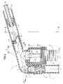
FIG. 1] FIG. 1 is a vertical sectional side view of a cleaner for the inside of a water tank (first embodiment). - [
FIG. 2] FIG. 2 is an enlarged view of an essential part ofFIG. 1 (first embodiment). - [
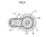
FIG. 3] FIG. 3 is a sectional view along line 3-3 inFIG. 2 (first embodiment). - [
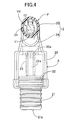
FIG. 4] FIG. 4 is a sectional view along line 4-4 inFIG. 2 (first embodiment). - [
FIG. 5] FIG. 5 is a diagram showing a state in which the cleaner for the inside of a water tank is in use (first embodiment). - [
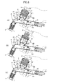
FIG. 6] FIG. 6 is a sectional view showing operation of the cleaner for the inside of a water tank (first embodiment). - [
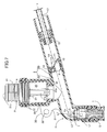
FIG. 7] FIG. 7 is a vertical sectional side view of an essential part of a cleaner for the inside of a water tank (second embodiment). - [
FIG. 8] FIG. 8 is a sectional view showing operation of the cleaner for the inside of a water tank (second embodiment). - [
FIG. 9] FIG. 9 is a vertical sectional side view of an essential part of a cleaner for the inside of a water tank (modified example of second embodiment). -
- 1
- Main body portion
- 2
- Grip portion
- 17
- Water-guiding pipe
- 20
- Operation tube
- 21
- Press button
- 22
- Seal ring
- 23
- Return spring
- 24
- Water passage
- 25
- Operation chamber
- A
- Suction operation tool
- P
- Suction pipe
- V
- Water tank
- Vu
- Upstream-side one-way valve
- Vd
- Downstream-side one-way valve
- Modes for carrying out the present invention are explained below by reference to embodiments of the present invention shown in the attached drawings.
- A first embodiment of the present invention is now explained by reference to
FIGS. 1 to 6 . - In
FIGS. 1 to 5 , a suction pipe P forming a main body part of a cleaner for the inside of a water tank is made with a transparent rigid synthetic resin material, and is formed in a dog-leg shape when viewed from the side from a straight cylindrical main body portion 1 that has an open extremity and is formed with a length that reaches to the bottom of a water tank V from the outside of the water tank V and agrip portion 2 bent so as to be communicatingly connected to the base end, that is, the downstream end, of the main body portion 1. Thegrip portion 2 is formed by removably and watertightly connecting anelbow pipe 2A and astraight pipe 2B. An angle formed by a central line L1 of the main body portion 1 and a central line L2 of thegrip portion 2 is an obtuse angle, that is, about 105°, and this makes it difficult for thegrip portion 2 to abut against an edge of the water tank V when the cleaner for the inside of a water tank is used, thus improving the operability. - A frustoconical strainer S having a large number of slits 3 made therein is provided in the interior of a part where the main body portion 1 and the
grip portion 2 of the suction pipe P are connected, and this strainer S permits the free passage of dirty water contaminated by fine waste material such as leftover food or fish excrement but prevents the passage of coarse waste material such as dead leaves or stones. An upstream-side one-way valve Vu is provided at the rear end, that is, anexit 4, of the strainer S. This upstream-side one-way valve Vu is formed from avalve hole 5 communicating with theexit 4 of the strainer S, and avalve body 6 that is connected by a hinge 7 to one side of thevalve hole 5 so as to open and close thevalve hole 5, and operates so as to permit the flow of water that has been sucked into the suction pipe P and passed through the strainer S but prevent the backflow thereof. - Furthermore, a downstream-side one-way valve Vd is provided within a downstream side section of the suction pipe P, which is on the downstream side relative to the upstream-side one-way valve Vu, that is, within an intermediate section of the
grip portion 2. This downstream-side one-way valve Vd is fixed within thegrip portion 2 and is formed from avalve seat body 9 having avalve hole 10 opening therein, and avalve body 11 that is connected by ahinge 12 to thevalve seat body 9 so as to open and close thevalve hole 10. Thevalve hole 10 is formed in an elliptical shape by obliquely cutting a cylindrical body, thevalve body 11 for opening and closing thevalve hole 10 is also formed in an elliptical shape and connected by thehinge 12 to an upper part side of the valve seat body 9 (when the cleaner is in use), and opening and closing of the downstream-side one-way valve Vd are thereby carried out smoothly by means of the hydraulic pressure of water flowing within the suction pipe P. - A
connection pipe 15 is integrally connected to the interior of the downstream end of thegrip portion 2, and thisconnection pipe 15 is connected to the upstream end of a water-guidingpipe 17. The water-guidingpipe 17 is formed from a flexible transparent pipe such as a vinyl chloride pipe. - As shown in
FIG. 5 , the water-guidingpipe 17 is formed in a length that enables the downstream end of the water-guidingpipe 17 to reach beneath the water level of the water tank V when the extremity of the suction pipe P faces the bottom part within the water tank V, that is, a length that can give a siphoning action for the cleaner, which is described later. - As shown in
FIG. 2 , between the main body portion 1 and thegrip portion 2 of the suction pipe P, a suction operation tool A for sucking water into the suction pipe P is provided in a bent connecting part thereof. This suction operation tool A is formed from acylindrical operation tube 20 that is provided integrally with the bent connecting part of the main body portion 1 and thegrip portion 2, is provided parallel to the main body portion 1, and has anoperation chamber 25 formed in the interior thereof, apress button 21 that is slidably fitted, via aseal ring 22, into theoperation chamber 25 from the outer end of the opening of theoperation tube 20, and areturn spring 23, which is a coil spring provided in a compressed state between the inner end of thepress button 21 and the base end of theoperation tube 20 within theoperation tube 20 and urging thepress button 21 so that it projects outside, aguide rod 21a fixed to the inner end of thepress button 21 slidably extending through aninner end wall 20a of theoperation tube 20. The interior of theoperation chamber 25 of theoperation tube 20 communicates with awater passage 24 between the upstream-side and downstream-side one-way valves Vu and Vd within the suction pipe P, and apress face 21 p is formed at the outer end of thepress button 21. When thepress button 21 is pressed in the direction shown by arrow a inFIG. 2 , thepress button 21 compresses thereturn spring 23 and moves inward within theoperation chamber 25 so as to pressurize thewater passage 24, thus closing the upstream-side one-way valve Vu and opening the downstream-side one-way valve Vd. When the pressing force on thepress button 21 is released, thepress button 21 is moved outward by the resilient force of thereturn spring 23 and returns to its original position (the position inFIG. 2 ), and thewater passage 24 is depressurized, thereby opening the upstream-side one-way valve Vu and closing the downstream-side one-way valve Vd at the same time. - The operation of the first embodiment is now explained by reference to
FIGS. 5 and6 . - (1) First, as shown in
FIG. 5 , after the open free end of the water-guidingpipe 17 is put into the interior of arecovery vessel 26 such as a bucket, the main body portion 1 of the suction pipe P is immersed in a vertical direction in water-tank water inside the water tank V by gripping thegrip portion 2. In this process, water inside the water tank V enters part way up the interior (water level) of the suction pipe P, both the upstream-side and downstream-side one-way valves Vu and Vd are opened, part of the air within the suction pipe P is discharged into the water-guidingpipe 17, and the air is released to the outside. - (2) Subsequently, as shown in
FIG. 6 (A) , while gripping thegrip portion 2, when thepress face 21 p of thepress button 21 of the suction operation tool A is pressed with a fingertip (pulling the press button 21) as shown by arrow a, thepress button 21 moves inward. This reduces the volume within theoperation chamber 25 and the interior of thewater passage 24 is pressurized, thus closing the upstream-side one-way valve Vu and opening the downstream-side one-way valve Vd. - (3) Subsequently, as shown in
FIG. 6 (B) , when the pressure on thepress button 21 is released, thepress button 21 moves outward as shown by arrow b, the volume of theoperation chamber 25 is increased, and the interior of thewater passage 24 is depressurized, thus opening the upstream-side one-way valve Vu and closing the downstream-side one-way valve Vd. - (4) As shown in
FIG. 6 (C) , when again pressing thepress button 21 as shown by arrow a, the interior of thewater passage 24 is pressurized again, thus closing the upstream-side one-way valve Vu and opening the downstream-side one-way valve Vd. - (5) As hereinbefore described, by repeating operations (2) to (4) several times, water-tank water inside the water tank V is forcibly sucked into the suction pipe P by the pumping action generated within the
operation chamber 25; thereafter, water flowing through the interior of the suction pipe P attains a continuous flow and water inside the water tank V is drained outside by means of a siphoning action without carrying out the above-mentioned operations. - After the operation of draining water by the siphoning action is established, as shown in
FIG. 5 , putting the upstream end of the suction pipe P, that is, the open free end, into gravel in the bottom part of the water tank V enables dirty water containing fine waste material such as leftover food or fish excrement to be sucked up and drained outside the water tank V through the suction pipe P and the water-guidingpipe 17. In this process, coarse waste material such as dead leaves contained in the dirty water is separated by means of the strainer S. The dirty water from which coarse waste material such as dead leaves has been separated and removed by the strainer S does not clog the upstream-side and downstream-side one-way valves Vu and Vd with waste material, and water can be smoothly sucked up and drained continuously. - When the suction force generated within the suction pipe P is large, fine particles such as gravel are sucked into the suction pipe P together with water-tank water, but in this case by pinching partway along the flexible water-guiding
pipe 17 with the fingertips, the suction force is reduced, and the fine particles sucked into the suction pipe P are returned to the water tank V. - In the above-mentioned operations of sucking up and draining dirty water, since the
operation tube 20 is provided substantially parallel to the main body portion 1 of the suction pipe P, the operational direction of the suction operation tool A coincides with the suction direction of water, it becomes easy to capture waste material in the bottom part of the water tank V, and this can be sucked up and drained together with dirty water quickly and efficiently. - A second embodiment of the present invention is now explained by reference to
FIGS. 7 and8 . - The second embodiment is different from the fist embodiment in terms of the position at which a suction operation tool A is mounted on a suction pipe P, as shown in
FIG. 7 , the suction operation tool A being provided in an upper part of the suction pipe P, that is, an upper wall of agrip portion 2. This suction operation tool A has the same structure as that of the first embodiment; anoperation tube 20 is formed integrally with an upper face of thegrip portion 2, thisoperation tube 20 extends upward substantially parallel to the main body portion 1, and anoperation chamber 25 within theoperation tube 20 is at a position outside and above awater passage 24 within the suction pipe P and communicates with thewater passage 24. Apress button 21 is slidably fitted via aseal ring 22 into theoperation tube 20 from the open upper end thereof, and apress face 21p is formed on an upper face of thepress button 21. - A
fingerhold piece 30 is formed integrally so as to straddle the base of theoperation tube 20 on the main body portion 1 side and the upper face of thegrip portion 2, and an arc-shapedfingerhold recess 31 for an operator to rest a finger on is formed on an edge part of thefingerhold portion 30. Furthermore, a hanginghole 32 is opened in thefingerhold piece 30. When the cleaner is not in use, it may be hung down from an appropriate hanger by utilizing the hanginghole 32. - As shown in
FIG. 8 (A) , when an operator grips thegrip portion 2, rests a finger on thefingerhold recess 31, and presses thepress face 21 p of thepress button 21 downward with another finger as shown by arrow a, in the same manner as in the first embodiment, the inner volume of theoperation chamber 25 decreases, and the interior of thewater passage 24 is pressurized, thus closing an upstream-side one-way valve Vu and opening a downstream-side one-way valve Vd. - Subsequently, as shown in
FIG. 8 (B) , when pressure on thepress button 21 is released, thepress button 21 moves outward as shown by arrow b, the inner volume of theoperation chamber 25 increases, and the interior of thewater passage 24 is depressurized, thus opening the upstream-side one-way valve Vu and closing the downstream-side one-way valve Vd. - Subsequently, as shown in
FIG. 8 (C) , when thepress button 21 is pressed again, the interior of thewater passage 24 is pressurized again, thus closing the upstream-side one-way valve Vu and opening the downstream-side one-way valve Vd. - By repeating the operations above several times, water-tank water inside the water tank V is forcibly sucked into the suction pipe P by the pumping action generated in the
operation chamber 25; thereafter, water flowing through the interior of the suction pipe P attains a continuous flow and water inside the water tank V is drained outside by means of a siphoning action without carrying out the above-mentioned operations. - In accordance with the second embodiment, since the suction operation tool A is at a position above the suction pipe P, and the
operation chamber 25 is at a position outside thewater passage 24 of the suction pipe P, in the suction pipe P, even if dirty water and fine foreign matter are sucked into the suction pipe P, there is no possibility of the foreign matter entering theoperation chamber 25 and being caught between theseal ring 22 and theoperation tube 20, and it is possible to guarantee smooth and appropriate operation of the suction operation tool A. - A modified example of the second embodiment is now explained by reference to
FIG. 9 . - This modified example is a case in which a suction operation tool A having the same structure as that of the second embodiment is provided at the upper end of a linear main body portion 1 of a suction pipe P; an
operation chamber 25 is at a position outside and above awater passage 24 of the suction pipe P, and the same operation and effects as those of the second embodiment can be exhibited. - Embodiments of the present invention are explained above, but the present invention is not limited to these embodiments, and various embodiments are possible within the scope of the present invention.
Claims (3)
- A cleaner for the inside of a water tank in which water-tank water within a water tank (V) is sucked up by a siphoning action and drained outside the water tank (V), the cleaner comprising
a suction pipe (P) formed from a linear main body portion (1) and a grip portion (2) bendingly connected to the main body portion (1),
a flexible water-guiding pipe (17) connected to the outer end of the suction pipe (P),
an upstream-side one-way valve (Vu) provided at an appropriate place within the main body portion (1) and only permitting the flow of water from the suction pipe (P) to the water-guiding pipe (17),
a downstream-side one-way valve (Vd) provided within the grip portion (2) and only permitting the flow of water from the suction pipe (P) to the water-guiding pipe (17), and
a suction operation tool (A) provided in a bent connecting part between the main body portion (1) and the grip portion (2) and pressurizing or depressurizing the interior of a water passage (24) between the upstream-side one-way valve (Vu) and the downstream-side one-way valve (Vd). - The cleaner for the inside of a water tank according to Claim 1, wherein the suction operation tool (A) is formed from an operation tube (20) connected so as to communicate with the interior of the water passage (24) and provided substantially parallel to the main body portion (1), a press button (21) slidably fitted into the operation tube (20) via a seal ring (22) and having an outer end thereof projecting outside the operation tube (20), and a return spring (23) provided within the operation tube (20) and urging the press button (21) toward the outside.
- A cleaner for the inside of a water tank in which water-tank water within a water tank (V) is sucked up by a siphoning action and drained outside the water tank (V), the cleaner comprising
a suction pipe (P) formed from a linear main body portion (1) and a grip portion (2) bendingly connected to the main body portion (1),
a flexible water-guiding pipe (17) connected to the outer end of the suction pipe (P),
an upstream-side one-way valve (Vu) provided at an appropriate place within the main body portion (1) and only permitting the flow of water from the suction pipe (P) to the water-guiding pipe (17),
a downstream-side one-way valve (Vd) provided within the grip portion (2) and only permitting the flow of water from the suction pipe (P) to the water-guiding pipe (17), and
a suction operation tool (A) provided above the suction pipe and pressurizing or depressurizing the interior of a water passage (24) between the upstream-side one-way valve (Vu) and the downstream-side one-way valve (Vd),
the suction operation tool (A) being formed from an operation tube (20) provided above an upper wall of the suction pipe and having an operation chamber (25) positioned above the water passage (24) within the suction pipe (P), a press button (21) slidably fitted into the operation chamber (25) via a seal ring (22) and projecting outside the operation tube (20), and a return spring (23) provided within the operation tube (20) and urging the press button (21) toward the outside.
Applications Claiming Priority (3)
| Application Number | Priority Date | Filing Date | Title |
|---|---|---|---|
| JP2008205807 | 2008-08-08 | ||
| JP2009047726A JP5129769B2 (en) | 2008-08-08 | 2009-03-02 | Aquarium cleaning tool |
| PCT/JP2009/062705 WO2010016362A1 (en) | 2008-08-08 | 2009-07-14 | Cleaning device for cleaning inside of water tank |
Publications (3)
| Publication Number | Publication Date |
|---|---|
| EP2301331A1 true EP2301331A1 (en) | 2011-03-30 |
| EP2301331A4 EP2301331A4 (en) | 2013-09-25 |
| EP2301331B1 EP2301331B1 (en) | 2016-06-22 |
Family
ID=41663585
Family Applications (1)
| Application Number | Title | Priority Date | Filing Date |
|---|---|---|---|
| EP09804849.9A Active EP2301331B1 (en) | 2008-08-08 | 2009-07-14 | Cleaning device for cleaning inside of water tank |
Country Status (7)
| Country | Link |
|---|---|
| US (1) | US8733385B2 (en) |
| EP (1) | EP2301331B1 (en) |
| JP (1) | JP5129769B2 (en) |
| KR (1) | KR101277610B1 (en) |
| CN (1) | CN102111994B (en) |
| TW (1) | TWI412319B (en) |
| WO (1) | WO2010016362A1 (en) |
Families Citing this family (9)
| Publication number | Priority date | Publication date | Assignee | Title |
|---|---|---|---|---|
| JP5497611B2 (en) * | 2010-10-20 | 2014-05-21 | 創市 小川 | Aquarium cleaning tool |
| CN102029270B (en) * | 2010-12-31 | 2013-08-28 | 甘继东 | Siphon device and siphon-type cleaning gun |
| CN102696530A (en) * | 2012-06-11 | 2012-10-03 | 天津开发区环海彩色包装印刷有限公司 | Automatic pumping device for aquarium |
| CN102907366A (en) * | 2012-10-24 | 2013-02-06 | 中国水产科学研究院南海水产研究所 | Water backflow preventive device of nanometer aerating tube for aquaculture |
| US10244738B1 (en) * | 2016-05-09 | 2019-04-02 | Bernard Ruiz | Temperature controlling aquarium cleaning device |
| JP7211589B2 (en) * | 2019-09-27 | 2023-01-24 | 水作株式会社 | Water flow control valve structure for water tank cleaning tools |
| JP7142879B2 (en) | 2020-03-23 | 2022-09-28 | 水作株式会社 | Water tank cleaning tool |
| KR102218828B1 (en) * | 2020-04-16 | 2021-02-22 | 노승룡 | Device for cleaning fish bowl |
| KR102436481B1 (en) * | 2022-03-29 | 2022-08-29 | 강원도 | Atlantic salmon mortality screening device. |
Citations (5)
| Publication number | Priority date | Publication date | Assignee | Title |
|---|---|---|---|---|
| JP368325Z2 (en) * | 1949-07-19 | 1949-12-12 | ||
| US3734853A (en) * | 1971-10-04 | 1973-05-22 | Holvin Prod Co | Suction cleaner for aquariums |
| JPS60185000A (en) * | 1984-03-03 | 1985-09-20 | Shigetomi Tanaka | Hose pump for suction and discharge |
| JP2000209978A (en) * | 1999-01-20 | 2000-08-02 | Suiken:Kk | Device for cleaning inside of water tank |
| US6926026B1 (en) * | 2003-10-08 | 2005-08-09 | William B. Burgoyne | Siphon initiating device |
Family Cites Families (22)
| Publication number | Priority date | Publication date | Assignee | Title |
|---|---|---|---|---|
| US383153A (en) * | 1888-05-22 | Siphon for starting the flow of liquids | ||
| US407971A (en) * | 1889-07-30 | Siphon | ||
| US151382A (en) * | 1874-05-26 | N combined siphons and filters | ||
| US232525A (en) * | 1880-09-21 | Siphon-pump | ||
| US238136A (en) * | 1881-02-22 | Siphon-pump | ||
| US136934A (en) * | 1873-03-18 | Improvement in acid-pumps | ||
| US1582399A (en) * | 1925-11-02 | 1926-04-27 | Victor W Helander | Siphon pump |
| US2325210A (en) * | 1941-08-18 | 1943-07-27 | Fred C Zieg | Liquid dispenser |
| US3158104A (en) * | 1961-12-20 | 1964-11-24 | Clyde E Hutchinson | Aquarium cleaning device |
| US3225930A (en) * | 1963-10-09 | 1965-12-28 | Aquariums Inc | Aquarium cleaning device |
| US3650473A (en) * | 1970-03-13 | 1972-03-21 | Afa Corp | Liquid dispensing apparatus |
| JPS5539370U (en) * | 1978-09-06 | 1980-03-13 | ||
| JPS5539370A (en) | 1978-09-14 | 1980-03-19 | Matsushita Graphic Commun Syst Inc | Ink jet recording device |
| JPS6062261U (en) * | 1983-10-05 | 1985-05-01 | 幸田 高俊 | Underwater filth collection tool |
| JP2536024Y2 (en) * | 1989-11-09 | 1997-05-21 | オリンパス光学工業株式会社 | Push button device |
| JPH0655087B2 (en) * | 1990-07-17 | 1994-07-27 | 株式会社水研 | Aquarium cleaning tool |
| CN2110735U (en) | 1991-12-30 | 1992-07-22 | 詹才赫 | Device for sucking dirt from bottom of pool or water vat |
| US6412528B1 (en) * | 2000-09-19 | 2002-07-02 | Peter Alex | Siphoning pump apparatus |
| US6948920B2 (en) * | 2001-12-19 | 2005-09-27 | Sws Corporation | Toilet bowl and tank drainage device |
| US6527202B1 (en) * | 2002-04-29 | 2003-03-04 | Living Fountain Plastic Industrial Co., Ltd. | Compression structure of a spray gun |
| US20070051320A1 (en) * | 2005-09-08 | 2007-03-08 | Yung-Hsin Yen | Dirt sucker for an aquarium |
| CN2857471Y (en) | 2005-11-28 | 2007-01-17 | 周海雄 | External aquarium vat automatic water suction filter |
-
2009
- 2009-03-02 JP JP2009047726A patent/JP5129769B2/en active Active
- 2009-07-14 WO PCT/JP2009/062705 patent/WO2010016362A1/en active Application Filing
- 2009-07-14 EP EP09804849.9A patent/EP2301331B1/en active Active
- 2009-07-14 US US13/002,405 patent/US8733385B2/en active Active
- 2009-07-14 KR KR1020117001409A patent/KR101277610B1/en active IP Right Grant
- 2009-07-14 CN CN2009801296679A patent/CN102111994B/en active Active
- 2009-07-20 TW TW98124418A patent/TWI412319B/en active
Patent Citations (5)
| Publication number | Priority date | Publication date | Assignee | Title |
|---|---|---|---|---|
| JP368325Z2 (en) * | 1949-07-19 | 1949-12-12 | ||
| US3734853A (en) * | 1971-10-04 | 1973-05-22 | Holvin Prod Co | Suction cleaner for aquariums |
| JPS60185000A (en) * | 1984-03-03 | 1985-09-20 | Shigetomi Tanaka | Hose pump for suction and discharge |
| JP2000209978A (en) * | 1999-01-20 | 2000-08-02 | Suiken:Kk | Device for cleaning inside of water tank |
| US6926026B1 (en) * | 2003-10-08 | 2005-08-09 | William B. Burgoyne | Siphon initiating device |
Non-Patent Citations (1)
| Title |
|---|
| See also references of WO2010016362A1 * |
Also Published As
| Publication number | Publication date |
|---|---|
| KR20110022062A (en) | 2011-03-04 |
| EP2301331B1 (en) | 2016-06-22 |
| TW201012386A (en) | 2010-04-01 |
| JP2010057475A (en) | 2010-03-18 |
| TWI412319B (en) | 2013-10-21 |
| US8733385B2 (en) | 2014-05-27 |
| KR101277610B1 (en) | 2013-06-28 |
| WO2010016362A1 (en) | 2010-02-11 |
| CN102111994B (en) | 2013-09-11 |
| CN102111994A (en) | 2011-06-29 |
| EP2301331A4 (en) | 2013-09-25 |
| JP5129769B2 (en) | 2013-01-30 |
| US20110120570A1 (en) | 2011-05-26 |
Similar Documents
| Publication | Publication Date | Title |
|---|---|---|
| EP2301331B1 (en) | Cleaning device for cleaning inside of water tank | |
| US4094788A (en) | Aquarium gravel cleaner | |
| US6499432B2 (en) | Cleaner for inside of water tank | |
| JP5497611B2 (en) | Aquarium cleaning tool | |
| US5542142A (en) | Pond cleaning device | |
| JP5143069B2 (en) | Aquarium cleaning tool with flow control device | |
| KR20220139980A (en) | tank interior cleaning device | |
| KR101769767B1 (en) | Removal apparatus of foreign material for water tank | |
| JP7211589B2 (en) | Water flow control valve structure for water tank cleaning tools | |
| JP3943694B2 (en) | Aquarium cleaning tool | |
| JP6461536B2 (en) | Aquarium treatment tool | |
| JP4929024B2 (en) | Aquarium cleaning tool | |
| KR100745465B1 (en) | Spuit type pumping device for aquarium | |
| JPH0475547A (en) | Cleaning tool in water tank | |
| JP2008194000A (en) | Tool for cleaning inside of water tank | |
| KR200412846Y1 (en) | Spuit type pumping device for aquarium | |
| JP4355916B2 (en) | Cleaning device |
Legal Events
| Date | Code | Title | Description |
|---|---|---|---|
| PUAI | Public reference made under article 153(3) epc to a published international application that has entered the european phase |
Free format text: ORIGINAL CODE: 0009012 |
|
| 17P | Request for examination filed |
Effective date: 20101228 |
|
| AK | Designated contracting states |
Kind code of ref document: A1 Designated state(s): AT BE BG CH CY CZ DE DK EE ES FI FR GB GR HR HU IE IS IT LI LT LU LV MC MK MT NL NO PL PT RO SE SI SK SM TR |
|
| AX | Request for extension of the european patent |
Extension state: AL BA RS |
|
| DAX | Request for extension of the european patent (deleted) | ||
| REG | Reference to a national code |
Ref country code: DE Ref legal event code: R079 Ref document number: 602009039376 Country of ref document: DE Free format text: PREVIOUS MAIN CLASS: A01K0063040000 Ipc: A01K0061000000 |
|
| A4 | Supplementary search report drawn up and despatched |
Effective date: 20130823 |
|
| RIC1 | Information provided on ipc code assigned before grant |
Ipc: A01K 61/00 20060101AFI20130819BHEP Ipc: F04F 10/00 20060101ALI20130819BHEP |
|
| 17Q | First examination report despatched |
Effective date: 20150422 |
|
| GRAP | Despatch of communication of intention to grant a patent |
Free format text: ORIGINAL CODE: EPIDOSNIGR1 |
|
| INTG | Intention to grant announced |
Effective date: 20160104 |
|
| GRAS | Grant fee paid |
Free format text: ORIGINAL CODE: EPIDOSNIGR3 |
|
| GRAA | (expected) grant |
Free format text: ORIGINAL CODE: 0009210 |
|
| AK | Designated contracting states |
Kind code of ref document: B1 Designated state(s): AT BE BG CH CY CZ DE DK EE ES FI FR GB GR HR HU IE IS IT LI LT LU LV MC MK MT NL NO PL PT RO SE SI SK SM TR |
|
| REG | Reference to a national code |
Ref country code: GB Ref legal event code: FG4D |
|
| REG | Reference to a national code |
Ref country code: CH Ref legal event code: EP |
|
| REG | Reference to a national code |
Ref country code: IE Ref legal event code: FG4D |
|
| REG | Reference to a national code |
Ref country code: AT Ref legal event code: REF Ref document number: 807099 Country of ref document: AT Kind code of ref document: T Effective date: 20160715 |
|
| REG | Reference to a national code |
Ref country code: DE Ref legal event code: R096 Ref document number: 602009039376 Country of ref document: DE |
|
| REG | Reference to a national code |
Ref country code: LT Ref legal event code: MG4D |
|
| REG | Reference to a national code |
Ref country code: NL Ref legal event code: MP Effective date: 20160622 |
|
| PG25 | Lapsed in a contracting state [announced via postgrant information from national office to epo] |
Ref country code: LT Free format text: LAPSE BECAUSE OF FAILURE TO SUBMIT A TRANSLATION OF THE DESCRIPTION OR TO PAY THE FEE WITHIN THE PRESCRIBED TIME-LIMIT Effective date: 20160622 Ref country code: NO Free format text: LAPSE BECAUSE OF FAILURE TO SUBMIT A TRANSLATION OF THE DESCRIPTION OR TO PAY THE FEE WITHIN THE PRESCRIBED TIME-LIMIT Effective date: 20160922 Ref country code: FI Free format text: LAPSE BECAUSE OF FAILURE TO SUBMIT A TRANSLATION OF THE DESCRIPTION OR TO PAY THE FEE WITHIN THE PRESCRIBED TIME-LIMIT Effective date: 20160622 |
|
| REG | Reference to a national code |
Ref country code: AT Ref legal event code: MK05 Ref document number: 807099 Country of ref document: AT Kind code of ref document: T Effective date: 20160622 |
|
| PG25 | Lapsed in a contracting state [announced via postgrant information from national office to epo] |
Ref country code: SE Free format text: LAPSE BECAUSE OF FAILURE TO SUBMIT A TRANSLATION OF THE DESCRIPTION OR TO PAY THE FEE WITHIN THE PRESCRIBED TIME-LIMIT Effective date: 20160622 Ref country code: LV Free format text: LAPSE BECAUSE OF FAILURE TO SUBMIT A TRANSLATION OF THE DESCRIPTION OR TO PAY THE FEE WITHIN THE PRESCRIBED TIME-LIMIT Effective date: 20160622 Ref country code: NL Free format text: LAPSE BECAUSE OF FAILURE TO SUBMIT A TRANSLATION OF THE DESCRIPTION OR TO PAY THE FEE WITHIN THE PRESCRIBED TIME-LIMIT Effective date: 20160622 Ref country code: GR Free format text: LAPSE BECAUSE OF FAILURE TO SUBMIT A TRANSLATION OF THE DESCRIPTION OR TO PAY THE FEE WITHIN THE PRESCRIBED TIME-LIMIT Effective date: 20160923 Ref country code: HR Free format text: LAPSE BECAUSE OF FAILURE TO SUBMIT A TRANSLATION OF THE DESCRIPTION OR TO PAY THE FEE WITHIN THE PRESCRIBED TIME-LIMIT Effective date: 20160622 |
|
| PG25 | Lapsed in a contracting state [announced via postgrant information from national office to epo] |
Ref country code: BE Free format text: LAPSE BECAUSE OF NON-PAYMENT OF DUE FEES Effective date: 20160731 |
|
| PG25 | Lapsed in a contracting state [announced via postgrant information from national office to epo] |
Ref country code: RO Free format text: LAPSE BECAUSE OF FAILURE TO SUBMIT A TRANSLATION OF THE DESCRIPTION OR TO PAY THE FEE WITHIN THE PRESCRIBED TIME-LIMIT Effective date: 20160622 Ref country code: SK Free format text: LAPSE BECAUSE OF FAILURE TO SUBMIT A TRANSLATION OF THE DESCRIPTION OR TO PAY THE FEE WITHIN THE PRESCRIBED TIME-LIMIT Effective date: 20160622 Ref country code: EE Free format text: LAPSE BECAUSE OF FAILURE TO SUBMIT A TRANSLATION OF THE DESCRIPTION OR TO PAY THE FEE WITHIN THE PRESCRIBED TIME-LIMIT Effective date: 20160622 Ref country code: IS Free format text: LAPSE BECAUSE OF FAILURE TO SUBMIT A TRANSLATION OF THE DESCRIPTION OR TO PAY THE FEE WITHIN THE PRESCRIBED TIME-LIMIT Effective date: 20161022 Ref country code: CZ Free format text: LAPSE BECAUSE OF FAILURE TO SUBMIT A TRANSLATION OF THE DESCRIPTION OR TO PAY THE FEE WITHIN THE PRESCRIBED TIME-LIMIT Effective date: 20160622 |
|
| PG25 | Lapsed in a contracting state [announced via postgrant information from national office to epo] |
Ref country code: ES Free format text: LAPSE BECAUSE OF FAILURE TO SUBMIT A TRANSLATION OF THE DESCRIPTION OR TO PAY THE FEE WITHIN THE PRESCRIBED TIME-LIMIT Effective date: 20160622 Ref country code: PT Free format text: LAPSE BECAUSE OF FAILURE TO SUBMIT A TRANSLATION OF THE DESCRIPTION OR TO PAY THE FEE WITHIN THE PRESCRIBED TIME-LIMIT Effective date: 20161024 Ref country code: BE Free format text: LAPSE BECAUSE OF FAILURE TO SUBMIT A TRANSLATION OF THE DESCRIPTION OR TO PAY THE FEE WITHIN THE PRESCRIBED TIME-LIMIT Effective date: 20160622 Ref country code: PL Free format text: LAPSE BECAUSE OF FAILURE TO SUBMIT A TRANSLATION OF THE DESCRIPTION OR TO PAY THE FEE WITHIN THE PRESCRIBED TIME-LIMIT Effective date: 20160622 Ref country code: AT Free format text: LAPSE BECAUSE OF FAILURE TO SUBMIT A TRANSLATION OF THE DESCRIPTION OR TO PAY THE FEE WITHIN THE PRESCRIBED TIME-LIMIT Effective date: 20160622 Ref country code: SM Free format text: LAPSE BECAUSE OF FAILURE TO SUBMIT A TRANSLATION OF THE DESCRIPTION OR TO PAY THE FEE WITHIN THE PRESCRIBED TIME-LIMIT Effective date: 20160622 |
|
| REG | Reference to a national code |
Ref country code: CH Ref legal event code: PL |
|
| REG | Reference to a national code |
Ref country code: DE Ref legal event code: R097 Ref document number: 602009039376 Country of ref document: DE |
|
| PG25 | Lapsed in a contracting state [announced via postgrant information from national office to epo] |
Ref country code: MC Free format text: LAPSE BECAUSE OF FAILURE TO SUBMIT A TRANSLATION OF THE DESCRIPTION OR TO PAY THE FEE WITHIN THE PRESCRIBED TIME-LIMIT Effective date: 20160622 |
|
| PG25 | Lapsed in a contracting state [announced via postgrant information from national office to epo] |
Ref country code: LI Free format text: LAPSE BECAUSE OF NON-PAYMENT OF DUE FEES Effective date: 20160731 Ref country code: FR Free format text: LAPSE BECAUSE OF NON-PAYMENT OF DUE FEES Effective date: 20160822 Ref country code: CH Free format text: LAPSE BECAUSE OF NON-PAYMENT OF DUE FEES Effective date: 20160731 |
|
| PLBE | No opposition filed within time limit |
Free format text: ORIGINAL CODE: 0009261 |
|
| REG | Reference to a national code |
Ref country code: FR Ref legal event code: ST Effective date: 20170331 |
|
| STAA | Information on the status of an ep patent application or granted ep patent |
Free format text: STATUS: NO OPPOSITION FILED WITHIN TIME LIMIT |
|
| REG | Reference to a national code |
Ref country code: IE Ref legal event code: MM4A |
|
| GBPC | Gb: european patent ceased through non-payment of renewal fee |
Effective date: 20160922 |
|
| 26N | No opposition filed |
Effective date: 20170323 |
|
| PG25 | Lapsed in a contracting state [announced via postgrant information from national office to epo] |
Ref country code: DK Free format text: LAPSE BECAUSE OF FAILURE TO SUBMIT A TRANSLATION OF THE DESCRIPTION OR TO PAY THE FEE WITHIN THE PRESCRIBED TIME-LIMIT Effective date: 20160622 |
|
| PG25 | Lapsed in a contracting state [announced via postgrant information from national office to epo] |
Ref country code: IE Free format text: LAPSE BECAUSE OF NON-PAYMENT OF DUE FEES Effective date: 20160714 Ref country code: GB Free format text: LAPSE BECAUSE OF NON-PAYMENT OF DUE FEES Effective date: 20160922 |
|
| PG25 | Lapsed in a contracting state [announced via postgrant information from national office to epo] |
Ref country code: SI Free format text: LAPSE BECAUSE OF FAILURE TO SUBMIT A TRANSLATION OF THE DESCRIPTION OR TO PAY THE FEE WITHIN THE PRESCRIBED TIME-LIMIT Effective date: 20160622 Ref country code: LU Free format text: LAPSE BECAUSE OF NON-PAYMENT OF DUE FEES Effective date: 20160714 |
|
| PG25 | Lapsed in a contracting state [announced via postgrant information from national office to epo] |
Ref country code: HU Free format text: LAPSE BECAUSE OF FAILURE TO SUBMIT A TRANSLATION OF THE DESCRIPTION OR TO PAY THE FEE WITHIN THE PRESCRIBED TIME-LIMIT; INVALID AB INITIO Effective date: 20090714 Ref country code: CY Free format text: LAPSE BECAUSE OF FAILURE TO SUBMIT A TRANSLATION OF THE DESCRIPTION OR TO PAY THE FEE WITHIN THE PRESCRIBED TIME-LIMIT Effective date: 20160622 |
|
| PG25 | Lapsed in a contracting state [announced via postgrant information from national office to epo] |
Ref country code: TR Free format text: LAPSE BECAUSE OF FAILURE TO SUBMIT A TRANSLATION OF THE DESCRIPTION OR TO PAY THE FEE WITHIN THE PRESCRIBED TIME-LIMIT Effective date: 20160622 Ref country code: MK Free format text: LAPSE BECAUSE OF FAILURE TO SUBMIT A TRANSLATION OF THE DESCRIPTION OR TO PAY THE FEE WITHIN THE PRESCRIBED TIME-LIMIT Effective date: 20160622 Ref country code: MT Free format text: LAPSE BECAUSE OF NON-PAYMENT OF DUE FEES Effective date: 20160731 |
|
| PG25 | Lapsed in a contracting state [announced via postgrant information from national office to epo] |
Ref country code: BG Free format text: LAPSE BECAUSE OF FAILURE TO SUBMIT A TRANSLATION OF THE DESCRIPTION OR TO PAY THE FEE WITHIN THE PRESCRIBED TIME-LIMIT Effective date: 20160622 |
|
| REG | Reference to a national code |
Ref country code: DE Ref legal event code: R082 Ref document number: 602009039376 Country of ref document: DE Representative=s name: WEICKMANN & WEICKMANN PATENT- UND RECHTSANWAEL, DE Ref country code: DE Ref legal event code: R081 Ref document number: 602009039376 Country of ref document: DE Owner name: SUISAKU KABUSHIKI KAISHA, TOKYO, JP Free format text: FORMER OWNER: OGAWA SOICHI, TOKYO 110-0016, TAITO-KU, JP |
|
| PGFP | Annual fee paid to national office [announced via postgrant information from national office to epo] |
Ref country code: IT Payment date: 20180703 Year of fee payment: 10 |
|
| PG25 | Lapsed in a contracting state [announced via postgrant information from national office to epo] |
Ref country code: IT Free format text: LAPSE BECAUSE OF NON-PAYMENT OF DUE FEES Effective date: 20190714 |
|
| PGFP | Annual fee paid to national office [announced via postgrant information from national office to epo] |
Ref country code: DE Payment date: 20230630 Year of fee payment: 15 |