EP2301487A2 - Implant and delivery system with multiple marker interlocks - Google Patents
Implant and delivery system with multiple marker interlocks Download PDFInfo
- Publication number
- EP2301487A2 EP2301487A2 EP10195028A EP10195028A EP2301487A2 EP 2301487 A2 EP2301487 A2 EP 2301487A2 EP 10195028 A EP10195028 A EP 10195028A EP 10195028 A EP10195028 A EP 10195028A EP 2301487 A2 EP2301487 A2 EP 2301487A2
- Authority
- EP
- European Patent Office
- Prior art keywords
- stent
- inner member
- implant
- distal
- sheath
- Prior art date
- Legal status (The legal status is an assumption and is not a legal conclusion. Google has not performed a legal analysis and makes no representation as to the accuracy of the status listed.)
- Granted
Links
- 239000007943 implant Substances 0.000 title claims abstract description 80
- 239000003550 marker Substances 0.000 title description 8
- 230000003014 reinforcing effect Effects 0.000 claims description 48
- 229920000642 polymer Polymers 0.000 claims description 18
- 229910052751 metal Inorganic materials 0.000 claims description 17
- 239000002184 metal Substances 0.000 claims description 17
- 239000011159 matrix material Substances 0.000 claims description 16
- BASFCYQUMIYNBI-UHFFFAOYSA-N platinum Chemical compound [Pt] BASFCYQUMIYNBI-UHFFFAOYSA-N 0.000 claims description 10
- 239000004642 Polyimide Substances 0.000 claims description 8
- 229920001721 polyimide Polymers 0.000 claims description 8
- 229920000728 polyester Polymers 0.000 claims description 7
- -1 polyethylene Polymers 0.000 claims description 7
- 229910001220 stainless steel Inorganic materials 0.000 claims description 7
- 229910045601 alloy Inorganic materials 0.000 claims description 6
- 239000000956 alloy Substances 0.000 claims description 6
- 239000010935 stainless steel Substances 0.000 claims description 6
- 239000004698 Polyethylene Substances 0.000 claims description 5
- PCHJSUWPFVWCPO-UHFFFAOYSA-N gold Chemical compound [Au] PCHJSUWPFVWCPO-UHFFFAOYSA-N 0.000 claims description 5
- 239000010931 gold Substances 0.000 claims description 5
- 229910052737 gold Inorganic materials 0.000 claims description 5
- 229910052697 platinum Inorganic materials 0.000 claims description 5
- 229920000573 polyethylene Polymers 0.000 claims description 5
- 229910052715 tantalum Inorganic materials 0.000 claims description 5
- GUVRBAGPIYLISA-UHFFFAOYSA-N tantalum atom Chemical compound [Ta] GUVRBAGPIYLISA-UHFFFAOYSA-N 0.000 claims description 5
- WFKWXMTUELFFGS-UHFFFAOYSA-N tungsten Chemical compound [W] WFKWXMTUELFFGS-UHFFFAOYSA-N 0.000 claims description 5
- 229910052721 tungsten Inorganic materials 0.000 claims description 5
- 239000010937 tungsten Substances 0.000 claims description 5
- 229920000271 Kevlar® Polymers 0.000 claims description 4
- 239000004696 Poly ether ether ketone Substances 0.000 claims description 4
- JUPQTSLXMOCDHR-UHFFFAOYSA-N benzene-1,4-diol;bis(4-fluorophenyl)methanone Chemical compound OC1=CC=C(O)C=C1.C1=CC(F)=CC=C1C(=O)C1=CC=C(F)C=C1 JUPQTSLXMOCDHR-UHFFFAOYSA-N 0.000 claims description 4
- 239000004761 kevlar Substances 0.000 claims description 4
- 239000004973 liquid crystal related substance Substances 0.000 claims description 4
- 229910001000 nickel titanium Inorganic materials 0.000 claims description 4
- HLXZNVUGXRDIFK-UHFFFAOYSA-N nickel titanium Chemical compound [Ti].[Ti].[Ti].[Ti].[Ti].[Ti].[Ti].[Ti].[Ti].[Ti].[Ti].[Ni].[Ni].[Ni].[Ni].[Ni].[Ni].[Ni].[Ni].[Ni].[Ni].[Ni].[Ni].[Ni].[Ni] HLXZNVUGXRDIFK-UHFFFAOYSA-N 0.000 claims description 4
- 229920002530 polyetherether ketone Polymers 0.000 claims description 4
- 239000004811 fluoropolymer Substances 0.000 claims description 3
- 229920002313 fluoropolymer Polymers 0.000 claims description 3
- 229920001187 thermosetting polymer Polymers 0.000 claims description 3
- 239000004812 Fluorinated ethylene propylene Substances 0.000 claims description 2
- 239000004743 Polypropylene Substances 0.000 claims description 2
- 229910000701 elgiloys (Co-Cr-Ni Alloy) Inorganic materials 0.000 claims description 2
- 230000001788 irregular Effects 0.000 claims description 2
- 239000005300 metallic glass Substances 0.000 claims description 2
- 229920009441 perflouroethylene propylene Polymers 0.000 claims description 2
- 229920001155 polypropylene Polymers 0.000 claims description 2
- 239000004810 polytetrafluoroethylene Substances 0.000 claims description 2
- 229920001343 polytetrafluoroethylene Polymers 0.000 claims description 2
- 229920001169 thermoplastic Polymers 0.000 claims description 2
- 239000004416 thermosoftening plastic Substances 0.000 claims description 2
- 239000004962 Polyamide-imide Substances 0.000 claims 2
- 229920002312 polyamide-imide Polymers 0.000 claims 2
- 230000000712 assembly Effects 0.000 abstract description 6
- 238000000429 assembly Methods 0.000 abstract description 6
- 239000000463 material Substances 0.000 description 41
- 238000000034 method Methods 0.000 description 24
- 238000011282 treatment Methods 0.000 description 19
- 208000027418 Wounds and injury Diseases 0.000 description 9
- 238000002594 fluoroscopy Methods 0.000 description 9
- 230000007246 mechanism Effects 0.000 description 9
- 210000004027 cell Anatomy 0.000 description 8
- 239000000919 ceramic Substances 0.000 description 8
- 238000003384 imaging method Methods 0.000 description 8
- 238000012800 visualization Methods 0.000 description 8
- 238000003466 welding Methods 0.000 description 7
- 238000010276 construction Methods 0.000 description 6
- 238000002595 magnetic resonance imaging Methods 0.000 description 6
- 150000002739 metals Chemical class 0.000 description 6
- 230000006835 compression Effects 0.000 description 5
- 238000007906 compression Methods 0.000 description 5
- 238000003698 laser cutting Methods 0.000 description 5
- 230000002787 reinforcement Effects 0.000 description 5
- 238000005452 bending Methods 0.000 description 4
- 210000004204 blood vessel Anatomy 0.000 description 4
- 230000008569 process Effects 0.000 description 4
- 239000002904 solvent Substances 0.000 description 4
- JHWNWJKBPDFINM-UHFFFAOYSA-N Laurolactam Chemical compound O=C1CCCCCCCCCCCN1 JHWNWJKBPDFINM-UHFFFAOYSA-N 0.000 description 3
- 239000004677 Nylon Substances 0.000 description 3
- 229920000299 Nylon 12 Polymers 0.000 description 3
- 238000004026 adhesive bonding Methods 0.000 description 3
- WYTGDNHDOZPMIW-RCBQFDQVSA-N alstonine Natural products C1=CC2=C3C=CC=CC3=NC2=C2N1C[C@H]1[C@H](C)OC=C(C(=O)OC)[C@H]1C2 WYTGDNHDOZPMIW-RCBQFDQVSA-N 0.000 description 3
- 230000001413 cellular effect Effects 0.000 description 3
- 238000005520 cutting process Methods 0.000 description 3
- 238000013461 design Methods 0.000 description 3
- 229920001778 nylon Polymers 0.000 description 3
- 239000007787 solid Substances 0.000 description 3
- 238000012360 testing method Methods 0.000 description 3
- 238000004804 winding Methods 0.000 description 3
- 239000004952 Polyamide Substances 0.000 description 2
- 239000004793 Polystyrene Substances 0.000 description 2
- 239000000853 adhesive Substances 0.000 description 2
- 230000001070 adhesive effect Effects 0.000 description 2
- 230000003872 anastomosis Effects 0.000 description 2
- 239000003462 bioceramic Substances 0.000 description 2
- 239000008280 blood Substances 0.000 description 2
- 210000004369 blood Anatomy 0.000 description 2
- 210000003850 cellular structure Anatomy 0.000 description 2
- 229940039231 contrast media Drugs 0.000 description 2
- 239000002872 contrast media Substances 0.000 description 2
- 230000007423 decrease Effects 0.000 description 2
- 239000003814 drug Substances 0.000 description 2
- 229940079593 drug Drugs 0.000 description 2
- 238000001125 extrusion Methods 0.000 description 2
- 239000012530 fluid Substances 0.000 description 2
- 238000002513 implantation Methods 0.000 description 2
- 230000007794 irritation Effects 0.000 description 2
- 238000002156 mixing Methods 0.000 description 2
- 238000012986 modification Methods 0.000 description 2
- 230000004048 modification Effects 0.000 description 2
- 230000037361 pathway Effects 0.000 description 2
- 238000013001 point bending Methods 0.000 description 2
- 229920002647 polyamide Polymers 0.000 description 2
- 239000004417 polycarbonate Substances 0.000 description 2
- 229920000515 polycarbonate Polymers 0.000 description 2
- 239000002861 polymer material Substances 0.000 description 2
- 229920002223 polystyrene Polymers 0.000 description 2
- 230000009467 reduction Effects 0.000 description 2
- 230000000717 retained effect Effects 0.000 description 2
- 238000000926 separation method Methods 0.000 description 2
- 239000000126 substance Substances 0.000 description 2
- 230000000451 tissue damage Effects 0.000 description 2
- 231100000827 tissue damage Toxicity 0.000 description 2
- 238000012285 ultrasound imaging Methods 0.000 description 2
- CWYNVVGOOAEACU-UHFFFAOYSA-N Fe2+ Chemical compound [Fe+2] CWYNVVGOOAEACU-UHFFFAOYSA-N 0.000 description 1
- 238000012307 MRI technique Methods 0.000 description 1
- 229920002614 Polyether block amide Polymers 0.000 description 1
- 238000009954 braiding Methods 0.000 description 1
- 210000000621 bronchi Anatomy 0.000 description 1
- QXJJQWWVWRCVQT-UHFFFAOYSA-K calcium;sodium;phosphate Chemical compound [Na+].[Ca+2].[O-]P([O-])([O-])=O QXJJQWWVWRCVQT-UHFFFAOYSA-K 0.000 description 1
- 210000001715 carotid artery Anatomy 0.000 description 1
- 238000004891 communication Methods 0.000 description 1
- 238000005056 compaction Methods 0.000 description 1
- 239000002131 composite material Substances 0.000 description 1
- 239000000470 constituent Substances 0.000 description 1
- 210000004351 coronary vessel Anatomy 0.000 description 1
- 230000008878 coupling Effects 0.000 description 1
- 238000010168 coupling process Methods 0.000 description 1
- 238000005859 coupling reaction Methods 0.000 description 1
- 229920006037 cross link polymer Polymers 0.000 description 1
- 238000004132 cross linking Methods 0.000 description 1
- 238000006073 displacement reaction Methods 0.000 description 1
- 238000005553 drilling Methods 0.000 description 1
- 230000000694 effects Effects 0.000 description 1
- 238000004070 electrodeposition Methods 0.000 description 1
- 210000003238 esophagus Anatomy 0.000 description 1
- 238000005530 etching Methods 0.000 description 1
- 239000000835 fiber Substances 0.000 description 1
- 230000004927 fusion Effects 0.000 description 1
- 210000004907 gland Anatomy 0.000 description 1
- 238000010438 heat treatment Methods 0.000 description 1
- 208000014674 injury Diseases 0.000 description 1
- 238000007689 inspection Methods 0.000 description 1
- 230000013011 mating Effects 0.000 description 1
- 239000004005 microsphere Substances 0.000 description 1
- 238000012544 monitoring process Methods 0.000 description 1
- 238000000465 moulding Methods 0.000 description 1
- RVTZCBVAJQQJTK-UHFFFAOYSA-N oxygen(2-);zirconium(4+) Chemical compound [O-2].[O-2].[Zr+4] RVTZCBVAJQQJTK-UHFFFAOYSA-N 0.000 description 1
- 230000036316 preload Effects 0.000 description 1
- 230000002028 premature Effects 0.000 description 1
- 238000004080 punching Methods 0.000 description 1
- 238000007789 sealing Methods 0.000 description 1
- 238000004904 shortening Methods 0.000 description 1
- 230000001954 sterilising effect Effects 0.000 description 1
- 238000004659 sterilization and disinfection Methods 0.000 description 1
- 238000003860 storage Methods 0.000 description 1
- 230000008733 trauma Effects 0.000 description 1
- 210000000626 ureter Anatomy 0.000 description 1
- 210000003708 urethra Anatomy 0.000 description 1
- 230000002792 vascular Effects 0.000 description 1
Images


Classifications
-
- A—HUMAN NECESSITIES
- A61—MEDICAL OR VETERINARY SCIENCE; HYGIENE
- A61F—FILTERS IMPLANTABLE INTO BLOOD VESSELS; PROSTHESES; DEVICES PROVIDING PATENCY TO, OR PREVENTING COLLAPSING OF, TUBULAR STRUCTURES OF THE BODY, e.g. STENTS; ORTHOPAEDIC, NURSING OR CONTRACEPTIVE DEVICES; FOMENTATION; TREATMENT OR PROTECTION OF EYES OR EARS; BANDAGES, DRESSINGS OR ABSORBENT PADS; FIRST-AID KITS
- A61F2/00—Filters implantable into blood vessels; Prostheses, i.e. artificial substitutes or replacements for parts of the body; Appliances for connecting them with the body; Devices providing patency to, or preventing collapsing of, tubular structures of the body, e.g. stents
- A61F2/95—Instruments specially adapted for placement or removal of stents or stent-grafts
- A61F2/962—Instruments specially adapted for placement or removal of stents or stent-grafts having an outer sleeve
- A61F2/966—Instruments specially adapted for placement or removal of stents or stent-grafts having an outer sleeve with relative longitudinal movement between outer sleeve and prosthesis, e.g. using a push rod
-
- A—HUMAN NECESSITIES
- A61—MEDICAL OR VETERINARY SCIENCE; HYGIENE
- A61F—FILTERS IMPLANTABLE INTO BLOOD VESSELS; PROSTHESES; DEVICES PROVIDING PATENCY TO, OR PREVENTING COLLAPSING OF, TUBULAR STRUCTURES OF THE BODY, e.g. STENTS; ORTHOPAEDIC, NURSING OR CONTRACEPTIVE DEVICES; FOMENTATION; TREATMENT OR PROTECTION OF EYES OR EARS; BANDAGES, DRESSINGS OR ABSORBENT PADS; FIRST-AID KITS
- A61F2/00—Filters implantable into blood vessels; Prostheses, i.e. artificial substitutes or replacements for parts of the body; Appliances for connecting them with the body; Devices providing patency to, or preventing collapsing of, tubular structures of the body, e.g. stents
- A61F2/82—Devices providing patency to, or preventing collapsing of, tubular structures of the body, e.g. stents
- A61F2/86—Stents in a form characterised by the wire-like elements; Stents in the form characterised by a net-like or mesh-like structure
- A61F2/90—Stents in a form characterised by the wire-like elements; Stents in the form characterised by a net-like or mesh-like structure characterised by a net-like or mesh-like structure
- A61F2/91—Stents in a form characterised by the wire-like elements; Stents in the form characterised by a net-like or mesh-like structure characterised by a net-like or mesh-like structure made from perforated sheet material or tubes, e.g. perforated by laser cuts or etched holes
- A61F2/915—Stents in a form characterised by the wire-like elements; Stents in the form characterised by a net-like or mesh-like structure characterised by a net-like or mesh-like structure made from perforated sheet material or tubes, e.g. perforated by laser cuts or etched holes with bands having a meander structure, adjacent bands being connected to each other
-
- A—HUMAN NECESSITIES
- A61—MEDICAL OR VETERINARY SCIENCE; HYGIENE
- A61F—FILTERS IMPLANTABLE INTO BLOOD VESSELS; PROSTHESES; DEVICES PROVIDING PATENCY TO, OR PREVENTING COLLAPSING OF, TUBULAR STRUCTURES OF THE BODY, e.g. STENTS; ORTHOPAEDIC, NURSING OR CONTRACEPTIVE DEVICES; FOMENTATION; TREATMENT OR PROTECTION OF EYES OR EARS; BANDAGES, DRESSINGS OR ABSORBENT PADS; FIRST-AID KITS
- A61F2/00—Filters implantable into blood vessels; Prostheses, i.e. artificial substitutes or replacements for parts of the body; Appliances for connecting them with the body; Devices providing patency to, or preventing collapsing of, tubular structures of the body, e.g. stents
- A61F2/95—Instruments specially adapted for placement or removal of stents or stent-grafts
- A61F2/9522—Means for mounting a stent or stent-graft onto or into a placement instrument
-
- A—HUMAN NECESSITIES
- A61—MEDICAL OR VETERINARY SCIENCE; HYGIENE
- A61F—FILTERS IMPLANTABLE INTO BLOOD VESSELS; PROSTHESES; DEVICES PROVIDING PATENCY TO, OR PREVENTING COLLAPSING OF, TUBULAR STRUCTURES OF THE BODY, e.g. STENTS; ORTHOPAEDIC, NURSING OR CONTRACEPTIVE DEVICES; FOMENTATION; TREATMENT OR PROTECTION OF EYES OR EARS; BANDAGES, DRESSINGS OR ABSORBENT PADS; FIRST-AID KITS
- A61F2/00—Filters implantable into blood vessels; Prostheses, i.e. artificial substitutes or replacements for parts of the body; Appliances for connecting them with the body; Devices providing patency to, or preventing collapsing of, tubular structures of the body, e.g. stents
- A61F2/82—Devices providing patency to, or preventing collapsing of, tubular structures of the body, e.g. stents
- A61F2/86—Stents in a form characterised by the wire-like elements; Stents in the form characterised by a net-like or mesh-like structure
- A61F2/90—Stents in a form characterised by the wire-like elements; Stents in the form characterised by a net-like or mesh-like structure characterised by a net-like or mesh-like structure
- A61F2/91—Stents in a form characterised by the wire-like elements; Stents in the form characterised by a net-like or mesh-like structure characterised by a net-like or mesh-like structure made from perforated sheet material or tubes, e.g. perforated by laser cuts or etched holes
- A61F2/915—Stents in a form characterised by the wire-like elements; Stents in the form characterised by a net-like or mesh-like structure characterised by a net-like or mesh-like structure made from perforated sheet material or tubes, e.g. perforated by laser cuts or etched holes with bands having a meander structure, adjacent bands being connected to each other
- A61F2002/91533—Stents in a form characterised by the wire-like elements; Stents in the form characterised by a net-like or mesh-like structure characterised by a net-like or mesh-like structure made from perforated sheet material or tubes, e.g. perforated by laser cuts or etched holes with bands having a meander structure, adjacent bands being connected to each other characterised by the phase between adjacent bands
- A61F2002/91541—Adjacent bands are arranged out of phase
-
- A—HUMAN NECESSITIES
- A61—MEDICAL OR VETERINARY SCIENCE; HYGIENE
- A61F—FILTERS IMPLANTABLE INTO BLOOD VESSELS; PROSTHESES; DEVICES PROVIDING PATENCY TO, OR PREVENTING COLLAPSING OF, TUBULAR STRUCTURES OF THE BODY, e.g. STENTS; ORTHOPAEDIC, NURSING OR CONTRACEPTIVE DEVICES; FOMENTATION; TREATMENT OR PROTECTION OF EYES OR EARS; BANDAGES, DRESSINGS OR ABSORBENT PADS; FIRST-AID KITS
- A61F2/00—Filters implantable into blood vessels; Prostheses, i.e. artificial substitutes or replacements for parts of the body; Appliances for connecting them with the body; Devices providing patency to, or preventing collapsing of, tubular structures of the body, e.g. stents
- A61F2/82—Devices providing patency to, or preventing collapsing of, tubular structures of the body, e.g. stents
- A61F2/86—Stents in a form characterised by the wire-like elements; Stents in the form characterised by a net-like or mesh-like structure
- A61F2/90—Stents in a form characterised by the wire-like elements; Stents in the form characterised by a net-like or mesh-like structure characterised by a net-like or mesh-like structure
- A61F2/91—Stents in a form characterised by the wire-like elements; Stents in the form characterised by a net-like or mesh-like structure characterised by a net-like or mesh-like structure made from perforated sheet material or tubes, e.g. perforated by laser cuts or etched holes
- A61F2/915—Stents in a form characterised by the wire-like elements; Stents in the form characterised by a net-like or mesh-like structure characterised by a net-like or mesh-like structure made from perforated sheet material or tubes, e.g. perforated by laser cuts or etched holes with bands having a meander structure, adjacent bands being connected to each other
- A61F2002/9155—Adjacent bands being connected to each other
- A61F2002/91558—Adjacent bands being connected to each other connected peak to peak
-
- A—HUMAN NECESSITIES
- A61—MEDICAL OR VETERINARY SCIENCE; HYGIENE
- A61F—FILTERS IMPLANTABLE INTO BLOOD VESSELS; PROSTHESES; DEVICES PROVIDING PATENCY TO, OR PREVENTING COLLAPSING OF, TUBULAR STRUCTURES OF THE BODY, e.g. STENTS; ORTHOPAEDIC, NURSING OR CONTRACEPTIVE DEVICES; FOMENTATION; TREATMENT OR PROTECTION OF EYES OR EARS; BANDAGES, DRESSINGS OR ABSORBENT PADS; FIRST-AID KITS
- A61F2/00—Filters implantable into blood vessels; Prostheses, i.e. artificial substitutes or replacements for parts of the body; Appliances for connecting them with the body; Devices providing patency to, or preventing collapsing of, tubular structures of the body, e.g. stents
- A61F2/82—Devices providing patency to, or preventing collapsing of, tubular structures of the body, e.g. stents
- A61F2/86—Stents in a form characterised by the wire-like elements; Stents in the form characterised by a net-like or mesh-like structure
- A61F2/90—Stents in a form characterised by the wire-like elements; Stents in the form characterised by a net-like or mesh-like structure characterised by a net-like or mesh-like structure
- A61F2/91—Stents in a form characterised by the wire-like elements; Stents in the form characterised by a net-like or mesh-like structure characterised by a net-like or mesh-like structure made from perforated sheet material or tubes, e.g. perforated by laser cuts or etched holes
- A61F2/915—Stents in a form characterised by the wire-like elements; Stents in the form characterised by a net-like or mesh-like structure characterised by a net-like or mesh-like structure made from perforated sheet material or tubes, e.g. perforated by laser cuts or etched holes with bands having a meander structure, adjacent bands being connected to each other
- A61F2002/9155—Adjacent bands being connected to each other
- A61F2002/91591—Locking connectors, e.g. using male-female connections
-
- A—HUMAN NECESSITIES
- A61—MEDICAL OR VETERINARY SCIENCE; HYGIENE
- A61F—FILTERS IMPLANTABLE INTO BLOOD VESSELS; PROSTHESES; DEVICES PROVIDING PATENCY TO, OR PREVENTING COLLAPSING OF, TUBULAR STRUCTURES OF THE BODY, e.g. STENTS; ORTHOPAEDIC, NURSING OR CONTRACEPTIVE DEVICES; FOMENTATION; TREATMENT OR PROTECTION OF EYES OR EARS; BANDAGES, DRESSINGS OR ABSORBENT PADS; FIRST-AID KITS
- A61F2/00—Filters implantable into blood vessels; Prostheses, i.e. artificial substitutes or replacements for parts of the body; Appliances for connecting them with the body; Devices providing patency to, or preventing collapsing of, tubular structures of the body, e.g. stents
- A61F2/95—Instruments specially adapted for placement or removal of stents or stent-grafts
- A61F2/962—Instruments specially adapted for placement or removal of stents or stent-grafts having an outer sleeve
- A61F2/966—Instruments specially adapted for placement or removal of stents or stent-grafts having an outer sleeve with relative longitudinal movement between outer sleeve and prosthesis, e.g. using a push rod
- A61F2002/9665—Instruments specially adapted for placement or removal of stents or stent-grafts having an outer sleeve with relative longitudinal movement between outer sleeve and prosthesis, e.g. using a push rod with additional retaining means
-
- A—HUMAN NECESSITIES
- A61—MEDICAL OR VETERINARY SCIENCE; HYGIENE
- A61F—FILTERS IMPLANTABLE INTO BLOOD VESSELS; PROSTHESES; DEVICES PROVIDING PATENCY TO, OR PREVENTING COLLAPSING OF, TUBULAR STRUCTURES OF THE BODY, e.g. STENTS; ORTHOPAEDIC, NURSING OR CONTRACEPTIVE DEVICES; FOMENTATION; TREATMENT OR PROTECTION OF EYES OR EARS; BANDAGES, DRESSINGS OR ABSORBENT PADS; FIRST-AID KITS
- A61F2220/00—Fixations or connections for prostheses classified in groups A61F2/00 - A61F2/26 or A61F2/82 or A61F9/00 or A61F11/00 or subgroups thereof
- A61F2220/0025—Connections or couplings between prosthetic parts, e.g. between modular parts; Connecting elements
- A61F2220/005—Connections or couplings between prosthetic parts, e.g. between modular parts; Connecting elements using adhesives
-
- A—HUMAN NECESSITIES
- A61—MEDICAL OR VETERINARY SCIENCE; HYGIENE
- A61F—FILTERS IMPLANTABLE INTO BLOOD VESSELS; PROSTHESES; DEVICES PROVIDING PATENCY TO, OR PREVENTING COLLAPSING OF, TUBULAR STRUCTURES OF THE BODY, e.g. STENTS; ORTHOPAEDIC, NURSING OR CONTRACEPTIVE DEVICES; FOMENTATION; TREATMENT OR PROTECTION OF EYES OR EARS; BANDAGES, DRESSINGS OR ABSORBENT PADS; FIRST-AID KITS
- A61F2220/00—Fixations or connections for prostheses classified in groups A61F2/00 - A61F2/26 or A61F2/82 or A61F9/00 or A61F11/00 or subgroups thereof
- A61F2220/0025—Connections or couplings between prosthetic parts, e.g. between modular parts; Connecting elements
- A61F2220/0058—Connections or couplings between prosthetic parts, e.g. between modular parts; Connecting elements soldered or brazed or welded
-
- A—HUMAN NECESSITIES
- A61—MEDICAL OR VETERINARY SCIENCE; HYGIENE
- A61F—FILTERS IMPLANTABLE INTO BLOOD VESSELS; PROSTHESES; DEVICES PROVIDING PATENCY TO, OR PREVENTING COLLAPSING OF, TUBULAR STRUCTURES OF THE BODY, e.g. STENTS; ORTHOPAEDIC, NURSING OR CONTRACEPTIVE DEVICES; FOMENTATION; TREATMENT OR PROTECTION OF EYES OR EARS; BANDAGES, DRESSINGS OR ABSORBENT PADS; FIRST-AID KITS
- A61F2230/00—Geometry of prostheses classified in groups A61F2/00 - A61F2/26 or A61F2/82 or A61F9/00 or A61F11/00 or subgroups thereof
- A61F2230/0002—Two-dimensional shapes, e.g. cross-sections
- A61F2230/0028—Shapes in the form of latin or greek characters
- A61F2230/0054—V-shaped
-
- A—HUMAN NECESSITIES
- A61—MEDICAL OR VETERINARY SCIENCE; HYGIENE
- A61F—FILTERS IMPLANTABLE INTO BLOOD VESSELS; PROSTHESES; DEVICES PROVIDING PATENCY TO, OR PREVENTING COLLAPSING OF, TUBULAR STRUCTURES OF THE BODY, e.g. STENTS; ORTHOPAEDIC, NURSING OR CONTRACEPTIVE DEVICES; FOMENTATION; TREATMENT OR PROTECTION OF EYES OR EARS; BANDAGES, DRESSINGS OR ABSORBENT PADS; FIRST-AID KITS
- A61F2250/00—Special features of prostheses classified in groups A61F2/00 - A61F2/26 or A61F2/82 or A61F9/00 or A61F11/00 or subgroups thereof
- A61F2250/0058—Additional features; Implant or prostheses properties not otherwise provided for
- A61F2250/0096—Markers and sensors for detecting a position or changes of a position of an implant, e.g. RF sensors, ultrasound markers
- A61F2250/0098—Markers and sensors for detecting a position or changes of a position of an implant, e.g. RF sensors, ultrasound markers radio-opaque, e.g. radio-opaque markers
Definitions
- the present invention relates to a system for delivering an implant to a site in a body lumen. More particularly, this invention pertains to a delivery system for a vascular implant such as a self-expanding stent.
- Stents are widely used for supporting a lumen structure in a patient's body.
- a stent may be used to maintain patency of a carotid artery, coronary artery, other blood vessel or other body lumen such as the ureter, urethra, bronchus, esophagus, or other passage.
- a stent is typically a metal, tubular structure, although polymer stents are known.
- Stents can be permanent enduring implants, or can be bioabsorbable at least in part.
- Bioabsorbable stents can be polymeric, bio-polymeric, ceramic, bio-ceramic, metallic, or other materials and stents may elute over time substances such as drugs.
- the stent is an open-celled tube that is expanded by an inflatable balloon at the deployment site.
- Another type of stent is of a "self-expanding" type.
- a self-expanding stent does not use a balloon or other source of force to move from a collapsed state to an expanded state.
- a self-expanding stent is passed through the body lumen in a collapsed state.
- the stent is expanded to its expanded diameter for its intended purpose.
- An example of a self-expanding stent is a coil structure that is secured to a stent delivery device under tension in a collapsed state.
- Coil stents can be manufactured using a variety of methods, such as winding of wire, ribbon, or sheet on a mandrel or by laser cutting from a tube, followed by the appropriate heat treatments.
- Other types of self expanding stents are closed-cell or open-celled tubes made from a self-expanding material, for example, the Protégé GPS stent from ev3, Inc. of Madison, MN.
- Cellular tube stents are commonly made by laser cutting of tubes, or cutting patterns into sheets followed by or preceded by welding the sheet into a tube shape, and other methods. The shape, length and other characteristics of a stent are typically chosen based on the location in which the stent will be deployed.
- Conventional stents generally are comprised of struts or wires having openings therebetween. Some workers in the field have added coverings to stents and thereby substantially occluded the stent openings. Examples of such devices include covered stents, stent-grafts, and mesh covered stents.
- covered stents and stent-grafts can be used as conduits for fluids in situations where little or no fluid loss through the wall of the conduit is desirable.
- mesh covered stents can be used to maintain a luminal diameter large enough to permit flow in the conduit yet prevent liberation of emboli from the wall of the lumen into the lumen.
- One delivery technique for a self expanding device such as a stent, covered stent, stent graft, or mesh covered stent is to mount the collapsed device on a distal end of a device delivery system.
- a device delivery system can be comprised of an outer tubular member and an inner tubular member.
- the inner and outer tubular members are axially slideable relative to one another.
- the device in the collapsed state
- the outer tubular member also called the outer sheath
- One or more portions of the device are releasably attached to the inner tubular member by means of interlock assemblies and the interlock assemblies facilitate proper positioning and control of the device during device deployment.
- a guide wire Prior to advancing the device delivery system through the body lumen, a guide wire is first passed through the body lumen to the deployment site.
- the inner tube of the delivery system is hollow throughout at least a portion of its length such that it can be advanced over the guide wire to the deployment site.
- the combined structure i.e., device mounted on device delivery system
- the deployment system should have good bending flexibility in order to traverse tortuous vessels encountered during system advancement to a treatment site, and the device may include radiopaque markers to permit a physician to visualize positioning of the device under fluoroscopy prior to deployment.
- the outer sheath is retracted to expose the device.
- the exposed device is free to self-expand within the body lumen.
- the inner tube is free to pass through the device such that the delivery system can be removed through the body lumen leaving the device in place at the deployment site.
- What is needed is a system that permits low deployment force of long devices, devices with a large amount of expansile force when compressed in a sheath, or devices compressed into small sheaths in tortuous vessels.
- the stent may prematurely deploy as the outer tube is retracted. Namely, with the outer tube partially retracted, the exposed portion of the stent may expand resulting in the remainder of the stent being squeezed out of the outer tube. This can result in the stent being propelled distally beyond a desired deployment site. Also, once the stent is partially unsheathed, it is sometimes determined that the stent placement needs to be adjusted. With some existing systems, this is difficult since the stent has a tendency to force itself out of the sheath thereby making adjustments difficult. Further, once the stent has been deployed, subsequent adjustment of the stent deployment location can be difficult because re-sheathing typically cannot be readily accomplished. To overcome some of these problems some stent delivery systems are comprised of interlocks on the stent and on the inner member.
- What is needed is a system that permits easy loading, precise delivery, and good visualization during deployment of long stents, thin stents, stents with a large amount of expansile force, and stents with high axial flexibility.
- An implant delivery system comprises one or more interlock assemblies which connect the implant delivery catheter to the implant, an improved inner tubular member and an outer tubular member.
- a distal interlock assembly prevents axial movement of the implant relative to the inner member during deployment.
- the improved inner tubular member is reinforced or made of a material which is able to resist inward radial compressive forces thereon from the implant during deployment of the implant.
- the implant is frictionally engaged against the inner surface of the outer tubular member prior to deployment and as the outer tubular member is withdrawn proximally during deployment.
- interlock assemblies improved inner tubular member and outer tubular member cooperate to place the implant in tension during deployment, resulting in a decrease in the constrained diameter of the implant during deployment and a lengthening of the constraint length of the implant thereby reducing implant deployment force.
- a proximal interlock assembly accommodates any increases in the constrained length of the implant at the proximal end thereof which accompany decreases in the constrained diameter of the implant caused by the tensioning of the implant during deployment.
- system for delivering a medical device within a body lumen comprises: a tubular catheter having an outer shaft member slidably disposed about an inner shaft member; a medical device comprising a tubular, self-expanding section carried by the inner shaft member and disposed intermediate the inner shaft member and the outer shaft member, the implant having a length I and a constrained diameter d which frictionally engages an inner surface of the outer shaft member; and a tensioning mechanism for causing tensioning of the medical device when the outer shaft member moves relative to the inner shaft member.
- the tensioning mechanism comprises a distal interlock structure carried by the inner member for preventing axial movement of a distal end of the implant when the outer sheath moves relative to the inner member.
- at least a portion of the inner member is formed of a material able to resist compression forces exerted thereon by said implant.
- the tensioning mechanism comprises a proximal interlock structure carried by the inner member and defining a receptacle for accommodating an increased length L of the implant when the outer sheath moves relative to the inner member.
- the tensioning mechanism comprises an inner surface of the outer sheath which frictionally engages at least a part of the implant when the outer sheath moves relative to the inner member.
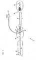
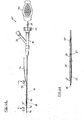
- Figure 1 illustrates a side elevation view of one embodiment of an implant delivery system having features that are examples of inventive aspects in accordance with the principles of the present disclosure
- Figure 2 illustrates an enlarged view of the distal end of the system of Figure 1 with the outer sheath shown in phantom line;
- Figure 3 illustrates the view of Figure 2 with the outer sheath retracted
- Figures 4A - 4G illustrate portions of the system of Figure 1 ;
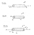
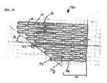
- FIGS. 5A and 5B illustrate plan views of exemplar medical device embodiments having features in accordance with the principles of the present disclosure.
- the medical devices are shown expanded, cut longitudinally and laid flat;
- Figure 5C illustrates side views of exemplar medical device embodiments having features in accordance with the principles of the present disclosure
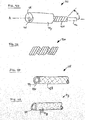
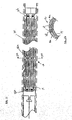
- FIGS 6A and 6B are side elevation views of an alternate embodiment of an implant delivery system having features that are examples of inventive aspects in accordance with the principles of the present disclosure
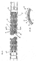
- FIGS 7A, 7B and 7C are side elevation views of an alternate embodiment of an implant delivery system having features that are examples of inventive aspects in accordance with the principles of the present disclosure
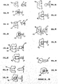
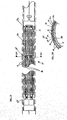
- Figures 8A to 8N illustrate plan views of stent delivery system interlock structures.
- the stent and the retainer are shown cut longitudinally and laid flat with an axial separation between the stent end and the mating retainer structure;
- Figure 9 is an enlarged view of the distal end of an embodiment of a stent delivery system having inventive aspects in accordance with the principles of the present disclosure with an outer sheath shown in phantom line;
- Figure 9A is a cross section of a portion of the stent system illustrated in Figure 5 ;
- Figures 10 and 11 illustrate side views of an exemplar stent embodiment having structure that interlocks with structure of a delivery catheter, the stent is shown expanded;
- Figure 12 illustrates a plan view of an exemplar stent embodiment having structure that interlocks with structure of a delivery catheter, the stent is shown expanded and the stent and interlock structures are shown cut longitudinally and laid flat;
- Figures 13 and 14 illustrate plan views of a section of an exemplar stent embodiment having structure that interlocks with structure of a delivery catheter, the stent is shown partially expanded and the stent segment and interlock structures are shown cut longitudinally and laid flat;
- Figure 15 illustrates plan views of a section of an exemplar stent embodiment having structure that interlocks with structure of a delivery catheter, the stent is shown contracted and the stent segment and interlock structures are shown cut longitudinally and laid flat;
- Figure 16 illustrates a plan view of a section of an exemplar stent embodiment having structure that interlocks with structure of a delivery catheter, the stent is shown partially expanded and the stent segment and interlock structures are shown cut longitudinally and laid flat;
- Figures 17 , 18 , 19 and 20 are enlarged views of the distal ends of embodiments of stent delivery systems having inventive aspects in accordance with the principles of the present disclosure with outer sheaths shown in phantom line;
- Figures 17A , 18A , 19A and 20A are cross sections of portions of the stent systems illustrated in Figures 17 , 18 , 19 and 20 , respectively;
- Figure 20B is a plan view of a portion of the stent system illustrated in Figure 27;
- Figures 21 and 22 are cross sections of portions of stent delivery systems having inventive aspects in accordance with the principles of the present disclosure.
- Figures 21A and 22A are plan views of portions of the stent delivery systems illustrated in Figures 21 and 22 , respectively.
- Figures 1-3 show an over-the-wire device delivery system, in this example stent delivery system 10 having distal and proximal ends 11, 13, inner member 14, and retractable outer sheath 16 that slides over inner member 14.
- Stent mounting location 26 is located adjacent distal end 11 of system 10.
- Stent 12 (visible in Figures 2 and 3 ) is carried at stent mounting location 26 of stent delivery system 10 in a collapsed (or reduced diameter) state. Stent 12 mounts over inner member 14 and is covered by sheath 16 so as to be retained in the collapsed state (see Figure 2 ).
- Stent 12 is released (i.e., deployed) by retracting sheath 16 to uncover or expose stent 12 (see Figure 3 ).
- System 10 includes proximal interlock structure 27 that prevents stent 12 from prematurely deploying, one or more optional mid interlock structures 28 that assist with uniform stent deployment and with stent loading, and distal interlock structure 29 that assists with stent deployment and with stent loading.
- proximal interlock structure 27 that prevents stent 12 from prematurely deploying
- one or more optional mid interlock structures 28 that assist with uniform stent deployment and with stent loading
- distal interlock structure 29 that assists with stent deployment and with stent loading.
- System 10 is configured to be advanced through the patient's body lumen. In use, system 10 is preferably sufficiently long for distal end 11 to be placed at the deployment site in the patient's body lumen with proximal end 13 remaining external to the patient's body for manipulation by an operator.
- Sheath 16 of system 10 may have a variety of different constructions.
- the sheath has a tubular construction of braid-reinforced polyester adapted to resist kinking and to transmit axial forces along the length of sheath 16.
- Sheath 16 may be constructed so as to have varying degrees of flexibility along its length.
- Inner member 14 of system 10 is relatively flexible in bending and has good column strength. Construction and function of inner member 14 is described in further detail below.
- inner member 14 has a tubular configuration and defines a lumen that extends through an entire length of inner member 14. This type of configuration allows the system to be passed over a guidewire for guiding the system to a desired deployment location.
- inner member 14 can have a solid, non-tubular configuration.
- Distal end 11 of system 10 includes a tapered and flexible distal tip member 30 that is sufficiently flexible to permit advancement of stent deployment system 10 through the patient's lumen while minimizing trauma to the walls of the patient's lumen.
- Tip 30 is connected to inner member 14 adjacent stent mounting location 26.
- Proximal end 13 of system 10 includes manifold housing 20 connected to lock housing 22.
- Sheath 16 connects to manifold housing 20.
- Strain relief jacket 24 surrounds sheath 16 adjacent its connection to housing 20 to provide strain relief for sheath 16.
- Inner member 14 passes through both manifold housing 20 and lock housing 22.
- Outer reinforcing member 32 surrounds and is bonded to inner member 14 adjacent proximal end 13 of system 10.
- Reinforcing member 32 may be made of a relatively rigid material such as stainless steel.
- Port housing 34 is bonded to reinforcing member 32.
- Port housing 34 has a bore aligned with an inner lumen of inner member 14 and functions to facilitate access to the inner lumen.
- Manifold housing 20 carries admission port 31 for injecting a contrast media into the interior of manifold housing 20.
- the interior of manifold housing 20 is in fluid communication with a passage between inner member 14 and sheath 16.
- the contrast media can be directed from the passage into the patient's body lumen through discharge ports (not shown).
- Lock housing 22 carries a threaded locking member (or lock nut) 35 which can be turned to engage reinforcing member 32.
- Lock nut 35 selectively permits and fixes axially movement between the inner member and sheath 16. Relative movement between the inner member and the sheath is permitted to define a transport position and a deploy position of the system 10.
- First and second handles 37, 39 are secured to lock housing 22 and reinforcing member 32, respectively.
- handles 37 and 39 are spaced apart and sheath 16 covers stent mounting location 26 to prevent premature deployment of stent 12.
- sheath 16 slides rearwardly or proximally relative to inner member 14-
- relative axial movement between handles 37 and 39 results in relative axial movement between inner member 14 and sheath 16.
- sheath 16 slides rearwardly from the transport position to the deploy position to fully expose stent mounting location 26 and permit stent 12 to freely expand toward its fully expanded diameter. After such expansion, the stent delivery system can be proximally withdrawn through the expanded stent and removed.
- delivery system 10 is comprised of an interlock configuration (e.g., interlock structures 27, 28, or 29 of Figures 2 and 3 ) that constrains relative axial movement between stent 12 and inner member 14 until after sheath 16 has been retracted.
- an interlock configuration e.g., interlock structures 27, 28, or 29 of Figures 2 and 3
- a proximal interlock geometry located at a proximal end 12a of stent 12 interlocks with proximal interlock structure 27 adjacent the stent mounting location 26
- a mid interlock geometry located at one or more locations along length of stent 12 interlocks with a mid interlock structure 28 adjacent the stent mounting location 26
- a distal interlock geometry located at a distal end 12b of stent 12 interlocks with a distal interlock structure 29 adjacent the stent mounting location 26.
- the interlock configurations remain interlocked to constrain axial movement of stent 12 until after the sheath has been retracted beyond a predetermined location (e.g., the proximal-most end 12a of stent 12).
- a predetermined location e.g., the proximal-most end 12a of stent 12.
- the interlock geometry of stent 12 is allowed to expand.
- the interlock geometry of stent 12 disengages from the proximal, mid, and distal interlock structures thereby allowing inner member 14 of system 10 to be moved axially relative to the stent without interference from the interlock configurations.
- Stent interlock structures 27, 28 and 29 are fixedly attached to inner member 14 adjacent mounting location 26.
- stent interlock structures 27, 28 and 29 can be bonded, crimped, swaged, affixed, fastened, fused, molded in, embedded in, or otherwise secured to inner member 14.
- Some embodiments include stent-retaining structures having interlocks formed as an integral/unitary structure with the inner member. In other embodiments stent retainers in the form of separate pieces can be secured to inner member 14.
- stent interlock structures 27, 28 and 29 may be comprised of stent ends having cavities and retainers comprising interlocking enlarged ends and located adjacent stent mounting location 26 of stent delivery system 10.
- stent interlock structures 27, 28 and 29 comprise opposing surfaces that mechanically interfere with proximal or distal movement of stent ends 12a, 12b along the lengthwise axis of the stent but which allow radial movement of stent ends 12a, 12b.
- Inner member 14, illustrated in Figure 4A is comprised of one or more materials having good flexibility when bent transverse to central axis A and high stiffness when compressed in direction of arrows B-B along central axis A.
- prior art inner members typically made of polymeric materials such as nylon, polyethylene, fluoropolymers, and other materials, have good flexibility when bent transverse to central axis A and but low stiffness when compressed in direction of arrows B-B along central axis A.
- Good flexibility when bent transverse to central axis A can be measured by standard 3 point bending tests.
- Inner member 14 may be comprised of crosslinked or non-crosslinked polymers that are extruded into the shape of tubing and then axially stretched to increase the relative orientation of the constituent polymer molecules along the axis A of the inner member. Inner member axial stretches from 100% to 1,000% are contemplated. In one embodiment inner member 14 is comprised of oriented polyester tubing having been axially stretched by 250% after extrusion. In another embodiment inner member 14 is comprised of oriented polyethylene tubing having been extruded, crosslinked, and axially stretched by 500% after crosslinking.
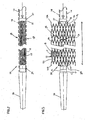
- Figures 4A - 4G illustrate examples of improved inner members.
- Figure 4B illustrates inner member 14b having reinforcing strands 42b embedded within matrix 44.
- Reinforcing strands 42b may be comprised of metal including but not limited to stainless steel, Elgiloy, superelastic alloys including Nitinol, gold, tantalum, tungsten, platinum, metallic glasses, and other metals; may be comprised of polymer including but not limited to PEEK, Liquid Crystal, polyester, Kevlar, polyamide, polyimide, and other polymers.
- reinforcing strands 42b may be round, flat, ovoid, square, triangular, polygonal, irregular, or other shapes. Reinforcing strand maximum cross-sectional transverse dimensions from .0005" to .005" are contemplated. In one embodiment reinforcing strands are comprised of .001" x .003" flat superelastic nitinol wire. In another embodiment reinforcing strands are comprised of .0015" diameter round stainless steel wire. Inner members 14b comprised of from 1 to 500 Reinforcing strands are contemplated. In one embodiment inner member 14b is comprised of 4 reinforcing strands.
- inner member 14b is comprised of 24 reinforcing strands.
- One, two, three, or more layers of reinforcing strands may be used.
- Matrix 44 may be comprised of polymer including but not limited to thermoplastics, thermosets, polyethylene, polypropylene, fluoropolymers such as FEP or PTFE, PEEK, Liquid Crystal, polyester, Kevlar, polyamide, polyimide, and other polymers.
- Matrix 44 may be comprised of one or more layers, and the one or more layers may be bonded together.
- Figure 4C illustrates inner layer 44x and outer layer 44y bonded to each other and to reinforcing strands 42c. Some or all of matrix layers and reinforcing strands may be bonded to each other using adhesive, solvent, heat, ultrasonic vibration, laser energy, radiofrequency energy, or other means.
- Reinforcing strands of improved inner member 14 can be configured in various ways and oriented in various directions relative to central axis A.
- Figure 4B illustrates improved inner member 14b comprised of reinforcing strands 42b embedded in matrix 44.
- Reinforcing strands 42b are configured in the shape of straight strands and are oriented parallel to central axis A.
- Reinforcing strands 42b can vary in number and spacing according to the relative dimensions of inner member 14b and strands 42b. In one embodiment adjacent strands 42b are separated by spaces and in another embodiment at least some of strands 42b are in side to side contact along at least a portion of their length.
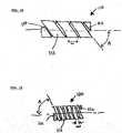
- Figure 4C illustrates improved inner member 14c comprised of reinforcing strands 42c embedded in matrix 44.
- Reinforcing strands 42c are configured in the shape of helical wound strands around central axis A. Angle G between helical wound strands 42c and central axis A is contemplated to be as low as 3 degrees and as high as 44 degrees. In one embodiment angle G between helical wound strands 42c and central axis A is between 10 and 35 degrees. In another embodiment angle G between helical wound strands 42c and central axis A is between 20 and 28 degrees.
- Reinforcing strands 42c can vary in number and spacing according to the relative dimensions of inner member 14c and strands 42c. In one embodiment adjacent strands 42c are separated by spaces and in another embodiment at least some of strands 42c are in side to side contact along at least a portion of their length.
- Figure 4D illustrates improved inner member 14d comprised of reinforcing strands 42d embedded in matrix 44 comprised of inner layer 44x and outer layer 44y bonded to each other and to reinforcing strands 42d.
- Reinforcing strands 42d are configured in the shape of coil wound strands around central axis A.
- Angle G between coil wound strands 42d and central axis A is contemplated to be as low as 45 degrees and as high as 87 degrees. In one embodiment angle G between helical wound strands 42d and central axis A is between 50 and 75 degrees. In another embodiment angle G between helical wound strands 42d and central axis A is between 60 and 70 degrees.
- Reinforcing strands 42d can vary in number and spacing according to the relative dimensions of inner member 14d and strands 42d. In one embodiment adjacent strands 42d are separated by spaces and in another embodiment at least some of strands 42d are in side to side contact along at least a portion of their length. In another embodiment reinforcement strands 42e are comprised of multifilar windings as illustrated in Figure 4E . In the example illustrated in Figure 4E reinforcement strands 42e are comprised of a 3-filar winding.
- Figure 4F illustrates improved inner member 14f comprised of reinforcing layer 42f embedded in matrix comprised of inner layer 44x and outer layer 44y bonded to each other and to reinforcing strands 42f.
- reinforcing layer 42f is configured in the shape of interwoven strands substantially concentrically arranged around central axis A. Reinforcing strands can vary in number and spacing according to the relative dimensions of inner member 14f and strands.
- Inner members comprised of from 3 to 72 reinforcing strands are contemplated.
- reinforcing layer 42f is comprised of 24 braided strands and in another embodiment reinforcing layer 42f is comprised of 48 braided strands.
- improved inner member 14f (0.380" inside diameter x 0.045" outside diameter) is comprised of 0.001" thick polyimide inner layer, 0.0015" thick nylon 12 outer layer and 16 braided type 304V stainless steel reinforcing strands of 0.0005" x 0.0030" flat wire with all 3 layers heat bonded to each other.
- reinforcing layer 42f may be comprised of tubes having holes, slots, or apertures formed therein, manufactured using processes such as etching, drilling, punching, laser cutting, electrodeposition, and other processes. One, two, three, or more concentric reinforcing layers may be used.
- improved inner member reinforcement layer 42f may be comprised of structures illustrated and described in U.S. Patent No. 6,290,692 , entitled “Catheter Support Structure” in U.S. Patent No. 6, 273, 876 , entitled “Catheter Segments Having Circumferential Supports With Axial Projection", the contents of which are incorporated herein in their entirety by this reference for all purposes.
- Figure 4G illustrates improved inner member 14g comprised of a composite of reinforcing strands 42g embedded in matrix 44.
- Reinforcing strands 42g are configured in the shape of straight strands and are oriented parallel to central axis A.
- Strands 42g commonly referred to as fiber reinforcements, have diameters ranging from 1 micron to 100 micron, and aspect ratio's (ratio of length to diameter) of between 5:1 and 50:1.
- improved inner member 14g is produced by blending polymer material matrix 44 with many thousands of strands 42g fallowed by extrusion or molding.
- Improved inner members 14g produced by blending polymer material matrix 44 with from 10,000 to 100,000,000 strands 42g over a cross section normal to the longitudinal axis of the inner member are contemplated.
- Stent 12 has a length I and a circumference C, and includes a plurality of struts 86 (i.e., reinforcing members). At least some of the struts 86 have free terminal ends 72 that define proximal and distal ends 12a and 12b of stent 12.
- Stent 12 includes an interlock geometry in the form of enlargements 36 positioned at the free terminal ends of struts 86. As shown in Figure 3 , the enlargements are circular enlargements. It will be appreciated that other interlock shapes and configurations could also be used. Enlargements 36 project outwardly from struts 86 in a circumferential direction (i.e. in a direction coinciding with the circumference C of stent 12). In one embodiment, stent 12 can be manufactured by cutting (e.g., laser cutting) the various features from a solid tube of material. When manufactured by this technique, enlargements 36 do not project radially beyond an inner and outer diameter of the stent.
- Stent configurations suitable for the invention include but are not limited to cellular stents, fracturable stents, coil stents, covered stents, stent grafts, mesh covered stents, tapered stents, flared stents, braided stents, bifurcation stents, and other stents as are known in the art. Long stents are especially suited to the invention. Medical device delivery systems for stents having lengths of from 40 - 400mm are contemplated. In one embodiment, a stent delivery system having improved inner member can deliver and deploy an 80mm stent. In another embodiment, a stent delivery system having improved inner member can deliver and deploy a 120mm stent.
- a stent delivery system having improved inner member can deliver and deploy a 150mm stent. In another embodiment, a stent delivery system having improved inner member can deliver and deploy a 180mm stent. In another embodiment, a stent delivery system having improved inner member can deliver and deploy a 200mm stent. In another embodiment, a stent delivery system having improved inner member can deliver and deploy a 250mm stent. In another embodiment, a stent delivery system having improved inner member can deliver and deploy a 300mm stent.
- Figure 5A illustrates stent 50a comprised of cells 52a, struts 54a, and radiopaque marker interlocks 36. Stent cells 52a are connected to adjacent cells 52a by means of interconnection regions 55a.
- Figure 5B illustrates fracturable stent 50b comprised of cells 52b, struts 54b, and radiopaque marker interlocks 36. Stent cells 52b are connected to adjacent cells 52b by means of fracturable interconnection regions 55b. Fracturable interconnection regions 55b are designed to fracture over time so as to improve fatigue life of stent 50b.
- FIG. 5C illustrates coil stent 50c comprised of ribbon or wire 56c and radiopaque marker interlocks 36.
- Ribbon or wire 56c has width W and is wound into a hollow cylinder form having a wind angle A.
- Ends 57c of ribbon may be rounded to prevent tissue damage or tissue irritation in vicinity of ends 57c when stent 50c is implanted into a patient.
- ribbon 56c is comprised of cells and struts arranged in an expandable architecture (not shown) having similarity to the cellular structures described in connection with at least Figures 5A and 5B .
- Improved inner member 14, interlock assembly(ies), and outer member cooperate to place the implant in tension during deployment, thereby reducing implant deployment force.
- implant 12 when sheath 16 is retracted implant 12 will attempt to retract with sheath 16 due to the frictional forces of the self expanding implant against inner diameter of sheath.
- enlarged ends 36 of implant 12 engaged with distal interlock structure 29 will prevent implant 12 from retracting proximally because interlock structure 29 is attached to inner member 14.
- Column strength of improved inner member 14 will resist compression and thereby place implant 12 in tension when sheath 16 is retracted.
- a 150mm stent deployed from a stent delivery system having mid or distal interlocks has a deployment force of 50 to 600 grams.
- a 150mm stent deployed from a stent delivery system having mid or distal interlocks has a deployment force of 100 to 400 grams. In another embodiment, a 150mm stent deployed from a stent delivery system having mid or distal interlocks has a deployment force of 150 to 300 grams. In an alternate embodiment, a 200mm stent deployed from a stent delivery system having mid or distal interlocks has a deployment force of 50 to 600 grams. In another embodiment, a 200mm stent deployed from a stent delivery system having mid or distal interlocks has a deployment force of 100 to 400 grams. In another embodiment, a 200mm stent deployed from a stent delivery system having mid or distal interlocks has a deployment force of 150 to 300 grams.
- distance between distal interlock structure 29 and proximal interlock structure 27 is longer than distance between distal end 12b of stent 12 and proximal end 12a of stent 12 in order to preload stent 12 into the delivery system under tension.
- column strength of improved inner member 14 resists axial compressive creep of inner member so that preloaded stent tension is maintained under storage, sterilization, and shipping conditions.
- Stents preloaded in tension to lengths 1% greater than their length under no tension within sheath 16, 66 ("1% preloaded tension") to lengths 15% greater than their length under no tension within sheath 16, 66 (“15% preloaded tension") are contemplated.
- stents are preloaded with 2% preloaded tension.
- stents are preloaded with 3% preloaded tension. In another embodiment, stents are preloaded with 5% preloaded tension. In another embodiment, stents are preloaded with 8% preloaded tension. In another embodiment, stents are preloaded with 12% preloaded tension.
- Rapid exchange stent delivery system 60 includes sheath 66 and inner member 64 disposed within sheath.
- Manifold housing 70 is coupled to sheath 66.
- Housing 70 includes side arm 72 and locking member 74.
- Push wire 68 is coupled to inner member 64 at its distal end and to handle 80 at its proximal end.
- Inner member 64 and sheath 66 are axially slideable relative to one another.
- Push wire 68 and housing 70 are used to facilitate movement of inner member 64 relative to sheath 66.
- Locking member 74 can be operated to couple housing 70 to push wire 68 in order to slide both sections along together.
- Relative movement between the inner member and the sheath is permitted to define a transport position and a deploy position of the system 60.
- Stent (not shown) mounts over inner member 64 and is covered by sheath 66 so as to be retained in the collapsed state. The stent is released (i.e., deployed) by retracting sheath 66 to uncover or expose stent.
- System 60 incudes proximal interlock structure 67 that prevents stent from prematurely deploying, one or more mid interlock structure (not shown) that assist with uniform stent deployment and with stent loading, and one or more distal interlock structure 69 that assist with uniform stent deployment and with stent loading.
- the stent Upon release of the stent from stent delivery system 60, the stent expands to an enlarged diameter to abut against the walls of the patient's lumen in order to support patency of the lumen. The expansion of the stent also causes stent to disengage from proximal, mid, and distal interlock structures.
- Sheath 66 may be made of kink resistant extruded polymer tubing with adequate strength and lubricity for unsheathing a stent. Polymers such as nylon, PEBAX, polyethylene, or polyester may be used. Alternatively, thermoset polymers such as polyimide or braid reinforced polyimide may be used. In some embodiments the distal portion of the outer member is transparent to allow inspection of the stent within.
- Inner member 64 is comprised of one or more materials having good flexibility when bent transverse to inner member central axis and high stiffness when compressed along inner member central axis. Inner member 64 is comprised of materials described in connection with the examples illustrated in Figures 4A - 4G .
- Push wire 68 in one embodiment is constructed of metal.
- proximal portion of push wire is comprised of stainless steel tubing and the distal portion of push wire 68 is comprised of metal wire.
- Housing 70 and locking member 74 may be comprised of polycarbonate, polystyrene, or other materials, and a sealing gland (not shown) may be used in cooperation with housing 70 and locking member 74 to effect a fiuid seal and/or mechanical lock between housing, locking member, and push wire 68 as is well known in the art.
- Handle 80 may be comprised of polycarbonate, polystyrene, nylon, or other materials. Alternate materials for these components are generally well known in the art and can be substituted for any of the non-limiting examples listed above provided the functional requirements of the component are met.
- Guidewire 90 has a nominal outer diameter of 0.010" - 0.038". In one embodiment guidewire 90 has a nominal outer diameter of 0.014". Inner member 64 and tip 62 are dimensioned to allow low friction passage of guidewire 90 within guide wire lumen 95 and through RX port 97.
- Guide wire lumen length can vary widely, but ranges in length from 5cm to 50cm are contemplated. In one embodiment guide wire lumen 95 is approximately 30cm in length.
- Sheath maximum outside diameter can range from about 10Fr to about 3Fr. A sheath outside diameter of about 5Fr is desirable for compatibility with currently popular guide catheter (not shown) dimensions. Sheath length can be varied to suit the application of interest. Sheath lengths of 40cm - 200cm are contemplated. In one embodiment sheath length is about 145cm.
- a guidewire is percutaneously inserted into a patient's blood vessel and advanced to a region of interest in the patienfs body.
- imaging techniques such as fluoroscopy a diseased portion of the vessel is identified and a stent having the correct length and diameter for treating the diseased portion is chosen.
- self expanding medical device delivery system 10, 60 loaded with stent 12 is advanced over the guidewire to the treatment site and by using imaging techniques such as fluoroscopy stent 12 is positioned at a correct location relative to the treatment site.
- Inner member 14, 64 is held stationary and sheath 16, 66 is withdrawn to expose stent 12. Stent 12 expands into contact with a lumenal wall of the vessel as sheath 16, 66 is withdrawn.
- Distal interlock 29, 69 in combination with column stiffness of improved inner member 14, 64 causes stent to axially elongate when sheath 16,66 is withdrawn, thereby reducing forces required to withdraw sheath 16, 66.
- Mid interlocks 28 (if used) in combination with column stiffness of improved inner member 14, 64 cause stent to axially elongate when sheath 16, 66 is withdrawn thereby reducing forces required to withdraw sheath 16, 66.
- Proximal interlocks 27, 67 secure stent to stent delivery catheter until sheath 16, 66 is withdrawn proximally of stent end 12a, thereby facilitating deployment of proximal end 12a of expanded stent at the correct location.
- stent markers 15 are imaged for various reasons including evaluating deployed stent position relative to treatment site, evaluating extent of stent diametrical expansion, and other reasons.
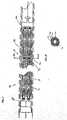
- Figures 7A, 7B and 7C show an alternate embodiment of a distal portion 70 of over the wire stent delivery system 10 or rapid exchange stent delivery system 60.
- Distal portion 70 is comprised of distal tip 80, distal retainer 29, self-expanding stent 12, inner member 74, sheath 76, and proximal, pusher 72.
- proximal pusher 72 is fixedly attached to inner member 14 adjacent stent mounting location 26.
- proximal pusher 72 can be bonded, crimped, swaged, affixed, fastened, fused, molded in, embedded in, or otherwise secured to inner member 14.
- a proximal pusher formed as an integral/unitary structure with the inner member.
- a proximal pusher in the form of a separate piece can be secured to inner member 14.
- a proximal pusher can be machined, etched, stamped, formed, or otherwise fabricated into the surface of a ring of metal, engineering polymer, ceramic, or other material and the ring applied to the inner member by adhesive bonding, welding, solvent welding, fusing, or other techniques known in the art.
- Proximal pusher 72 is comprised of channels 72A sized to slideably receive one or more stent end 12A.
- Figure 7A illustrates two stent ends 12A positioned at a distance distal to proximal pusher 72 and Figure 7B illustrates one stent end 12A positioned within each channel 72A of proximal pusher 72.
- Proximal pusher 72 is further comprised of deflecting ends 72B configured to deflect stent ends 12A into channel 72A.
- deflecting ends 72B have a shape similar to that of the leading portion of a bullet.
- deflecting ends 72B have round, ovoid, pointed, tapered, or other shapes that will deflect stent ends away from deflecting ends 72B (in direction of either arrow in Figure 7C ) and into channels 72A.
- gap D there is a gap D between proximal pusher 72 and proximal-most end 12a of stet 12. Gaps D ranging from 1mm to 15mm are contemplated. In one embodiment gap D is 3mm long. In another embodiment gap D is 5mm long. In another embodiment gap D is 8mm long. In another embodiment gap D is 12mm long.
- Stent delivery systems have been manufactured according to the principles of the invention and have been found to have superior stent deployment forces as shown in the examples below.
- Example 1 Stents 6mm in diameter and 150mm or 200mm long and having structures similar to that shown in Figure 5A were laser cut from binary nitinol alloy tubing, expanded, and heat treated using processes known in the art. Stents (150mm- long or 200mm long) were mounted on prior art Stent Delivery Systems (SDS) and stents (200mm long) were mounted on inventive SDS.
- SDS Stent Delivery Systems
- inventive SDS were identical to prior art SDS except that 1) distal interlocks were present on inventive SDS and absent on prior art SDS, and 2) inventive SDS were comprised of proximal pushers while prior art SDS were comprised of proximal retainers, and 3) inventive SDS were comprised of improved inner members while prior art SDS were comprised of prior art inner members.
- Improved inner members (0.380" inside diameter x 0.045" outside diameter) were comprised of 0.001" thick polyimide inner layer, 0.0015" thick nylon 12 outer layer and 16 braided type 304V stainless steel reinforcing strands of 0-0005" x 0.0030" flat wire. All 3 layers were heat bonded to each other.
- Prior art inner members of the same overall dimensions were comprised of non-reinforced nylon 12. Both stent delivery systems were tested for maximum stent deployment force under similar testing conditions.
- the inventive SDS has superior measured characteristics as compared to the prior art SDS.
- 6mm x 200mm stents both the average deployment force and the variability of deployment force were reduced due to the inventive design.
- 6 of 21 6mm x 200mm stents were unable to be deployed in the prior art SDS because the SDS fractured under excessively high deployment forces.
- 6mm x 150mm stents in prior art SDS had similar deployment forces as longer stents (6mm x 200mm) in inventive SDS. This is particularly significant because longer stents have been shown to require higher deployment forces than shorter stents in a given SDS.
- a guidewire is percutaneously inserted into a patient's blood vessel and advanced to a region of interest in the patient's body.
- imaging techniques such as fluoroscopy a diseased portion of the vessel is identified and a stent having the correct length and diameter for treating the diseased portion is chosen.
- Inner member 14, 64 is held stationary and sheath 16, 66 is withdrawn to expose stent 12. Due to friction, self expanding stent 12 will move proximally with sheath 16,66 but distal retainer in cooperation with distal ends of stent and improved inner member 14, 64 will prevent stent distal ends from moving proximally. Because of this, stent 12 will lengthen and reduce gap D, thus reducing its constrained diameter, reducing the frictional force of the stent against the inside diameter of the sheath, and thereby reducing the force needed for initial stent deployment. The sheath will retract relative to the distal end of the stent a small amount, allowing the distal ends of the stent to radially expand and thereby free themselves from the distal retainer 29.
- the stent will move proximally with the sheath 16, 66, further reducing gap D, until the stent proximal ends bottom out in channels 72A of proximal pusher 27 and gap D is reduced to zero. At this point continued withdrawal of sheath will cause proximal pusher 72 to push stent 12 out of sheath 16, 66. Stent 12 expands into contact with a lumenal wall of the vessel as sheath 16, 66 is withdrawn.
- stent markers 15 are imaged for various reasons including evaluating deployed stent position relative to treatment site, evaluating extent of stent diametrical expansion, and other reasons.
- Stent 12 has a deployed length L and a circumference C, and includes a plurality of struts 86 (i.e., reinforcing members). At least some of the struts 86 have free terminal ends 72 that define proximal and distal ends 12a and 12b of the stent 12.
- the stent 12 includes an interlock geometry in the form of enlargements 47 positioned at the free terminal ends of the struts 86. As shown in Figure 3 , the enlargements are circular enlargements. It will be appreciated that other shapes and interlock configurations could also be used.
- the enlargements 47 project outwardly from the struts 86 in a circumferential direction (i.e.
- the stent 12 can be manufactured by cutting (e.g., laser cutting) the various features from a solid tube of material.
- cutting e.g., laser cutting
- the enlargements 47 do not project radially beyond an inner and outer diameter of the stent.
- Stent interlock structures 27, 28 and 29 may be comprised of enlarged stent ends (designated generically as 12x in Figures 8A through 8N ) and retainers (designated generically as cavities 14y or pin 14z in the Figures) and are located adjacent stent mounting location 26 of stent delivery system 10.
- Stent interlock structures 27, 28 and 29 comprised of retainers 14y, 14z and may be are preferably fixedly attached to inner member 14 adjacent mounting location 26.
- stent interlock structures 27, 28 and 29 can be bonded, crimped, swaged, affixed, fastened, fused, molded in, embedded in, or otherwise secured to inner member 14.
- stent interlock structures 27, 28 and 29 may be comprised of stent ends having cavities and retainers comprised of interlocking enlarged ends and are located adjacent stent mounting location 26 of stent delivery system 10.
- Figures 8A through 8N illustrate 7 different exemplary interlock configurations.
- one or more of the interlock configurations illustrated in Figures 8A through 8N are applied to either proximal end 12a or distal end 12b of stent 12 and to corresponding locations of inner member 14.
- one or more of the interlock configurations illustrated in Figures 8A through 8N are applied to stent 12 in between proximal) end 12a and distal end 12b of stent 12.
- stent ends 12x are shown in relation to corresponding retainers 14y, 14z.
- paired Figures i.e.
- Figures 8A-8B, 8C-8D, 8E-8F, 8G-8H, 8I-8J, 8K-8L and 8M-8N the stent end and the retainer have been cut longitudinally and laid flat.
- the retainer 14y or 14z and the stent end 12x are shown disengaged from one another.
- the retainer and the stent end are shown interlocked.
- interlock configurations illustrated in Figures 8A through 8N are comprised of opposing surfaces 101 that mechanically interfere with proximal or distal movement of stent ends 12x relative to retainers 14y, 14z along the lengthwise axis of stent but which allow radial movement of the stent ends 12x out of the retainers 14y, 14z.
- stent 12 is comprised of retainers as part of stent ends 12x and inner member 14 is comprised of corresponding interlock geometry.
- stent ends 12x are comprised of one or more imagable markers 15 as illustrated in Figures 8A and 8B .
- stent 12 includes radiopaque markers 15 that permit a physician to accurately determine the position of stent 12 within the patient's lumen under fluoroscopic visualization.
- stent 12 includes ultrasonic markers 15 that permit a physician to accurately determine the position of stent 12 within the patient's lumen under ultrasonic visualization.
- stent 12 includes. MRI safe markers 15 that permit a physician to accurately determine the position of stent 12 within the patient's lumen under magnetic resonance imaging.
- Ultrasonic and MRI visualization are especially useful for visualizing stent 12 during non-invasive follow-up and monitoring.
- Markers 15 may be are preferably located adjacent the proximal or distal ends 12a, 12b of stent 12 or both and may be located along the length of the stent between the proximal and distal stent ends 12a, 12b. Markers 15 can be attached to stent 12 by techniques such as adhesive, beat fusion, interference fit, fasteners, intermediate members or other techniques. Materials for making radiopaque marker 15 should have a density suitable for visualization through fluoroscopic techniques. Preferably, the Mmarkers may have a radiopacity substantially greater than the material forming the struts of the stent.
- Exemplary materials comprise tantalum, platinum, gold, tungsten and alloys of such metals.
- the markers can be coated with a radiopaque material or filled with radiopaque material.
- Materials for making ultrasonic marker 15 should have an acoustical density sufficiently different from stent 12 to provide suitable visualization through ultrasonic techniques.
- Exemplary materials comprise polymers (for metallic stents), metals such as tantalum, platinum, gold, tungsten and alloys of such metals (for polymeric or ceramic stents), hollow glass spheres or microspheres, and other materials.
- Materials for making MRI safe marker 15 should be non-ferrous and have a magnetic signature sufficiently different from stent 12 to provide suitable visualization through MRI techniques.
- Exemplary materials comprise polymers (for metallic stents), metals such as tantalum, platinum, gold, tungsten and alloys of such metals (for polymeric or ceramic stents), and other materials.
- markers 15 are at least partially defined at the interlock geometries located at the ends of stent 12.
- enlargements 47 may define openings in the form of through-holes or through-apertures (i.e., holes that extend completely through the enlargements 47) within which markers 15 may be positioned.
- markers in the form of insert pieces can be press-fit or riveted within the through-holes.
- the enlargements may include openings in the form of recesses (depressions that extend partially through the enlargements) within which marker 15 may be placed.
- Positioning markers 15 on ends 12a, 12b of stent 12 provides precise stent location information to a physician, even after deployment and removal of the stent delivery device.
- stent-retaining structures having interlocks formed as an integral/unitary structure with the inner member.
- stent retainers in the form of separate pieces can be secured to inner member 14.
- retainers 14y, 14z can be machined, etched, stamped, formed, or otherwise fabricated into the surface of a ring of metal, engineering polymer, ceramic, or other material and the ring applied to inner member 14-19 by adhesive bonding, welding, solvent welding, fusing, or other techniques known in the art.
- FIGS 9 and 9A illustrate an alternative embodiment of stent mid interlock geometry 28.
- Stent 12 is comprised of retainers 12y in the form of pockets or voids in the compressed stent structure.
- One or more protrusion 14x emanate from inner member 14 and in another embodiment are integral to and fixedly attached to inner member 14 adjacent mounting location 26.
- protrusion 14x can be bonded, crimped, swaged, affixed, fastened, fused, molded in, embedded in, raised from or otherwise secured to inner member 14.
- mid interlock geometry 28 is applied to stent 12 and inner member 14 in between proximal end 12a and distal end 12b of stent 12 at one or more locations along the length of the stent.
- Figures 9 and 9A illustrate retainers 12y and protrusions 14x in an interlocked configuration.
- Mid-interlocks are particularly useful for stents ranging from between any of 100mm to 500mm in length, more preferably ranging from 150 to 300mm in length, or and more preferably ranging even from 150 to 200 mm in length.
- Coil stents 110, 120 are comprised of ribbon 111 having width W, wound into a hollow cylinder form and having a wind angle A.
- Stent 120 is comprised of ribbon 111 having width W less than width of ribbon in stent 110, and having wind angle A greater than wind angle A of ribbon in stent 110.
- Ends 112 of ribbon may be rounded to prevent tissue damage or tissue irritation in vicinity of ends 112 when stent 110, 120 is implanted into a patient.
- Ribbon 111 may be comprised of metal, polymer, ceramic, permanent enduring materials, or bioabsorbable materials.
- Bioabsorbable ribbons 111 can be polymeric, bio-polymeric, ceramic, bio-ceramic, or metallic, or may be made from combinations of these materials. Bioabsorbable and non-bioabsorbable ribbons 111 may elute over time substances such as drugs.
- the stencil stranded in figures 10 and 11 may be modified to include any of the interlock configurations described herein, one of which is illustrated in Figure 5C . It is contemplated that the interlock geometries and configurations described herein may be implemented with various stent types and designs, in addition to those disclosed herein, for example with those published in International Application PCT/US 05/015596 , Publication Number WO 2006/116383 , the subject matter of which is incorporated herein by reference.
- Ribbon 111 is comprised of an expandable architecture 130.
- An expandable architecture 130 is illustrated in Figure 12 .
- Ribbon 111 is shown partially expanded and the ribbon and interlock structures are shown cut longitudinally and laid flat.
- Expandable architecture 130 is comprised of enlarged ends 47, mid-stent retainer pockets 12y, struts 86, bend regions 19, and one or more interconnection regions 113. Struts 86 and bend regions 19 together form a zig-zag shaped expandable architecture of ribbon 111.
- Other expandable architectures are contemplated for expandable architecture of ribbon 111 such as various serpentine or meandering paths.
- Interconnection regions 113 join adjacent ribbons 111 and can fracture in a controlled manner such that when fractured interconnection regions 113 no longer join adjacent ribbons 111.
- interconnection regions 113 are comprised holes 114 in bend regions 19 and one or more strand 115.
- Strand 115 passes through holes 114 along a pathway that joins together adjacent ribbons 111.
- strand 115 passes through holes 114 in adjacent bend regions 19 and forms a closed loop.
- Strand 115 is comprised of a material that fractures in a controlled manner, and may be formed of biodegradable suture or other materials.
- interconnection regions 113 are comprised of a biodegradable coupling such as a tube that surrounds bend regions 19.
- interconnection regions 113 are comprised of a biodegradable rivet that passes through holes 114 in adjacent bend regions 19.
- Figure 14 illustrates stent 140 having interlock structures that interlock with interlock geometry of a delivery catheter, comprised of ribbon 111 having expandable architecture 142.
- Expandable architecture 142 is comprised of enlarged ends 47, mid-stent retainer pockets 12y, struts 86, bend regions 19, and one or more interconnection regions 113. Struts 86 and bend regions 19 together form a zig-zag shaped expandable architecture of ribbon 111.
- Other expandable architectures are contemplated for expandable architecture of ribbon 111 such as various serpentine or meandering paths.
- Interconnection regions 113 join adjacent ribbons 111 and can fracture in a controlled manner such that when fractured, interconnection regions 113 no longer join adjacent ribbons 111.
- Interconnection regions 113 are comprised of expanded ends 116 and receiver ends 117 in bend regions 19. Expanded ends 116 and receiver ends 117 join together adjacent ribbons 111, presenting axial separation of adjacent ribbons when stent 140 is contracted or expanded. Expanded ends 116 and receiver ends 117 may translate relative to one another in a radial direction relative to the stent longitudinal axis such that adjacent ribbons 111 are no longer joined together. Many other expanded end / receiver end geometries beyond that illustrated are possible provided the functional requirements of ends 116, 117 are met, as will be apparent to those skilled in the art.
- Figure 15 illustrates stent 150 having interlock structure that interlocks with interlock geometry of a delivery catheter, comprised of ribbon 111 having expandable architecture 152.
- Expandable architecture 152 is comprised of enlarged ends 47, mid-stent retainer pockets 12y, struts 86, bend regions 19, and one or more Interconnection regions 113. Struts 86 and bend regions 19 together form a zig-zag shaped expandable architecture of ribbon 111.
- Other expandable architectures are contemplated for expandable architecture of ribbon 111 such as various serpentine or meandering paths.
- Interconnection regions 113 join adjacent ribbons 111 and can fracture in a controlled manner such that when fractured, interconnection regions 113 no longer join adjacent ribbons 111.
- Interconnection regions 113 are comprised interdigitating ends 118 in bend regions 19. Interdigitating ends 118 join together adjacent ribbons 111 by mechanical interference against each other when stent 150 is contracted. Upon expansion of stent 150 interdigitating ends 118 become separated along circumference of stent 150 such that adjacent ribbons 111 are no longer joined together. Many other interdigitating end geometries beyond that illustrated are possible provided the functional requirements of ends 118 are met, as will be apparent to those skilled in the art.
- Figure 16 illustrates another example of an expandable architecture 130.
- Expandable architecture 130 is comprised of cells 18, enlarged ends 47, mid-stent retainer pockets 12y, struts 86, bend regions 19, and one or more interconnection regions 113.
- Struts 86 and bend regions 19 together form a cellular expandable architecture of ribbon 111 with similarities to the cellular structures described in connection with at least Figures 2, 3 , 5 , 7 , 8 , 10, 11 and 12 .
- interconnection regions 113 join adjacent ribbons 111 and can fracture in a controlled manner such that when fractured, interconnection regions 113 no longer join adjacent ribbons 111.
- Interconnection regions 113 may be comprised of expanded ends 116 and receiver ends 117, interdigitating ends 118, or other structures.
- stents having interlock structure that interlocks with interlock geometry of a delivery catheter may be comprised tapered stents, flared stents, braided stents, bifurcation stents, and other stents as are known in the art.
- Tapered stents generally have a proximal end of one diameter and a distal end of a second diameter (typically a smaller diameter).
- Flared stents generally have a short tapered portion at the proximal end of a cylindrical stent, where the flared section is larger in diameter than the cylindrical portion.
- Braided stents are typically comprised of a tube manufactured by using a braiding method.
- An example of a braided stent is the Wallstent, sold by Boston Scientific, Natick, MA.
- Bifurcation stents are placed in a patient where a vessel branches.
- Bifurcation stents are generally comprised of a single stent portion that branches into two stent portions and appears similar to a Y-fitting used to connect one piece of tubing to two pieces of tubing.
- FIGS 17 and 17A illustrate an alternative embodiment of stent mid interlock geometry 28.
- Stent 160 is comprised of retainers 12y in the form of widened stent struts 86e having holes 162 in the widened stent struts 86e.
- One or more pins 164 emanate from inner member 14 and in a one embodiment are integral to and fixedly attached to inner member 14.
- pin 164 can be bonded, crimped, swaged, affixed, fastened, fused, molded in, embedded in, or otherwise secured to inner member 14.
- pins 164 When stent 160 is compressed onto inner member 14 pins 164 are inserted into holes 162 and axial motion of stent 160 relative to inner member 14 is prevented thereby.
- mid interlock geometry 28 is applied to stent 12 and inner member 14 in between proximal end 12a and distal end 12b of stent 12 at one or more locations along the length of the stent.
- Figures 17 and 17A illustrate pins 164 and holes 162 in an interlocked configuration. When stent is expanded holes 162 move away radially from inner member 14 thereby removing pins 164 from holes 162 and releasing interlock 28.
- FIGS 18 and 18A illustrate an alternative embodiment of stent mid interlock geometry 28.
- Stent 170 is comprised of retainers 12y in the form of one or more bend regions 19 having enlarged ends 47 with holes 172.
- One or more pins 174 emanate from inner member 14 and in, a one embodiment, are integral to and fixedly attached to inner member 14.
- pin 174 can be bonded, crimped, swaged, affixed, fastened, fused, molded in, embedded in, or otherwise secured to inner member 14.
- pins 174 are inserted into holes 172 and axial motion of stent 170 relative to inner member 14 is prevented thereby.
- mid interlock geometry 28 is applied to stent 12 and inner member 14 in between proximal end 12a and distal end 12b of stent 12 at one or more locations along the length of the stent.
- Figures 18 and 18A illustrate pins 174 and holes 172 in an interlocked configuration. When stent is expanded holes 172 move away radially from inner member 14 thereby removing pins 174 from holes 172 and releasing interlock 28.
- FIGS 19 and 19A illustrate an alternative embodiment of stent mid interlock geometry 28.
- Stent 180 is comprised of retainers 14y in the form of one or more pockets in interlock band 186.
- Interlock band is preferably comprised of metal having machined, etched, formed, or stamped pockets, although other constructions are possible, as is known in the art.
- Stent bend regions 19 may have extended ends 184 with angled geometry that interlocks with retainer pockets.
- interlock band 186 is fixedly attached to inner member 14.
- band 186 can be bonded, crimped, swaged, affixed, fastened, fused, molded in, embedded in, or otherwise secured to inner member 14.
- FIGS 20, 20A and 20B illustrate an alternative embodiment of stent mid interlock geometry 28.
- Stent 180 is comprised of retainers 12y in the form of spaces between compressed stent struts 86.
- One or more ridges 192 emanate from inner member 14 and in a one embodiment are integral to and fixedly attached to inner member 14.
- ridge 192 can be bonded, crimped, swaged, affixed, fastened, fused, molded in, embedded in, or otherwise secured to inner member 14.
- ridges 192 are inserted into spaces between compressed stent struts 86 and axial motion of stent 190 relative to inner member 14 is prevented thereby.
- mid interlock geometry 28 is applied to stent 12 and inner member 14 in between proximal end 12a and distal end 12b of stent 12 at one or more locations along the length of the stent.
- Figures 20, 20A and 20B illustrate ridges 192 and spaces between compressed stent struts 86 in an interlocked configuration. When stent is expanded spaces between compressed stent struts 86 move away radially from inner member 14 thereby removing ridges 192 from spaces between compressed stent struts 86 and releasing interlock 28.
- FIGS 21 and 21A illustrate an alternative embodiment of stent mid interlock geometry 28.
- Stent 200 is comprised of retainers 12v in the form of one or more bumps 202 on stent struts 86 and in a one embodiment are integral to and fixedly attached to stent struts 86.
- bump 202 can be bonded, crimped, swaged, affixed, fastened, fused, molded in, embedded in, or otherwise secured to stent strut 86.
- Inner member 14 is comprised of one or more divots 204 When stent 200 is compressed onto inner member 14 bumps 202 substantial fill divots 204 and axial motion of stent 200 relative to inner member 14 is prevented thereby.
- mid interlock geometry 28 is applied to stent 12 and inner member 14 in between proximal end (not shown) and distal end (not shown) of stent 200 at one or more locations along the length of the stent.
- Figures 21 and 21A illustrate bumps 202 and divots 204 in an interlocked configuration. When stent is expanded bumps 202 move away radially from inner member 14 thereby removing bumps 202 from divots 204 and releasing interlock 28.
- FIGS. 22 and 22A illustrate an alternative embodiment of stent mid interlock geometry 28.
- Stent 210 is comprised of retainers 12w in the form of one or more cavities 212 on stent struts 86.
- Inner member 14 is comprises d of one or more mesa's 214 and in a one embodiment mesa's 214 are integral to and fixedly attached to inner member 14.
- mesa's 214 can be bonded, crimped, swaged, affixed, fastened, fused, molded in, embedded in, or otherwise secured to inner member 14.
- When stent 210 is compressed onto inner member 14 mesa's 214 substantially fill cavities 212 and axial motion of stent 210 relative to inner member 14 is prevented thereby.
- mid interlock geometry 28 is applied to stent 12 and inner member 14 in between proximal end (not shown) and distal end (not shown) of stent 210 at one or more locations along the length of the stent.
- Figures 22 and 22A illustrate mesa's 214 and cavities 212 in an interlocked configuration. When stent is expanded mesa's 214 move away radially from inner member 14 thereby removing mesa's 214 from cavities 212 and releasing interlock 28.
- the stent is covered by the loading tube except for the distal interlock structure 26 which is left projecting outside of the end of the loading tube.
- the inner member 14, 64 of stent delivery catheter 10, 60 having interlock structure is extended outside of sheath 16, 66 of said stent delivery catheter and the compressed stent in loading tube is slid over inner member 14, 64, Distal stent and stent delivery catheter interlocks are connected and the loading tube is slid over the connected distal interlocks to expose proximal interlock structure 27 of the stent 12.
- Proximal stent and stent delivery catheter interlocks are connected and the sheath is slid over the connected proximal interlocks.
- the stent loading tube is withdrawn a short distance to expose a portion of the stent and the sheath is advanced to cover the exposed portion.
- mid interlock structures 28, if used, are connected.
- Stent length after loading is also close to stent length prior to loading in a system having mid or distal interlocks. In prior art devices without mid or distal interlocks stent length after loading can be as little as 90% of stent length prior to loading. In a one embodiment of a stent system having inventive interlocks, stent length after loading is 95 - 105% of stent length prior to loading. In another more embodiment of a stent system having inventive interlocks, stent length after loading is 98 - 102% of stent length prior to loading. In another more embodiment of a stent system having inventive interlocks, stent length after loading is 99 - 101% of stent length prior to loading.
- a guidewire is percutaneously inserted into a patient's blood vessel and advanced to a region of interest in the patient's body.
- imaging techniques such as fluoroscopy the diseased portion of the vessel is identified and a stent having the correct length and diameter for a treatment site is chosen.
- self expanding stent delivery system 10, 60 is advanced over the guidewire to the treatment site and by using imaging techniques such as fluoroscopy both ends 12a, 12b of stent 12 are positioned at a correct location relative to the treatment site.
- Inner member 14, 64 is held stationary and sheath 16, 66 is withdrawn to exposed stent 12.
- Stent 12 expands into contact with a lumenal wall of the vessel as sheath 16, 66 is withdrawn.
- Distal interlock 26 prevents stent from shortening due to axial compression when sheath 16, 66 is withdrawn, thereby facilitating deployment of distal end 12b of expanded stent at the correct location and reducing forces required to withdraw sheath 16, 66.
- Mid interlocks 28 (if used) prevent stent from compressing axially when sheath 16, 66 is withdrawn thereby reducing forces required to withdraw sheath 16, 66.
- Proximal interlocks 27 secure stent to stent delivery catheter until sheath 16, 66 is withdrawn proximally to stent end 12a, thereby thereby reducing forces required to withdraw sheath 16, 66 and facilitating deployment of proximal, end 12a of expanded stent at the correct location.
- stent markers 15 are imaged for various reasons including evaluating deployed stent position relative to treatment site, evaluating extent of stent diametrical expansion, and other reasons.
- stent length after deployment is close to stent length prior to deployment.
- stent length after deployment can be as little as 90% of stent length prior to deployment, a disadvantage requiring the use of additional stents to treat the treatment area.
- stent length after loading may be any of is 95 - 105% of stent length prior to loading, more preferably 98 - 102% of stent length prior to loading, or and even more preferably 99 - 101 % of stent length prior to loading.
- a 150mm stent deployed from a stent delivery system having mid or distal interlocks has may have a stent deployment force of between any of 50 to 600 grams, more preferably 100 to 400 grams, or and even more preferably 100 to 300 grams.
- a 200mm stent deployed from a stent delivery system having mid or distal interlocks may have has a stent deployment force of between any of 50 to 600 grams, more preferably 100 to 400 grams, or and even more preferably 100 to 300 grams.
- the patient may return to the implanting physician for a follow-up visit.
- the markers 15 of implanted stent 12 may be imaged using imaging techniques such as fluoroscopy, ultrasound, or magnetic resonance imaging to assess the position of stent 12 relative to the treatment site, to evaluate the expanded diameter of stent 12, or for other reasons.
- the various embodiments of the present invention have related to a stent and a stent delivery system, the scope of the present invention is not so limited.
- the various aspects of the present invention are also applicable to systems for delivering other types of expandable implants.
- other types of expanding implants include anastomosis devices, blood filters, grafts, vena cava filters, percutaneous valves, aneurism treatment devices, or other devices.
- stent length after deployment is close to stent length prior to deployment.
- stent length after deployment can be as little as 90% of stent length prior to deployment, a disadvantage requiring the use of additional stents to treat the treatment area.
- stent length after loading may be any of is 95 - 105% of stent length prior to loading, more preferably 98 -102% of stent length prior to loading, or and even more preferably 99 - 101% of stent length prior to loading.
- a 150mm stent deployed from a stent delivery system having mid or distal interlocks has may have a stent deployment force of between any of 50 to 600 grams, more preferably 100 to 400 grams, or and even more preferably 100 to 300 grams.
- a 200mm stent deployed from a stent delivery system having mid or distal interlocks may have has a stent deployment force of between any of 50 to 600 grams, more preferably 100 to 400 grams, or and even more preferably 100 to 300 grams.
- the patient may return to the implanting physician for a follow-up visit.
- the markers 15 of implanted stent 12 may be imaged using imaging techniques such as fluoroscopy, ultrasound, or magnetic resonance imaging to assess the position of stent 12 relative to the treatment site, to evaluate the expanded diameter of stent 12, or for other reasons.
- a system for delivering an implant within a body lumen comprising:
Abstract
Description
- The present invention relates to a system for delivering an implant to a site in a body lumen. More particularly, this invention pertains to a delivery system for a vascular implant such as a self-expanding stent.
- Stents are widely used for supporting a lumen structure in a patient's body. For example, a stent may be used to maintain patency of a carotid artery, coronary artery, other blood vessel or other body lumen such as the ureter, urethra, bronchus, esophagus, or other passage. A stent is typically a metal, tubular structure, although polymer stents are known. Stents can be permanent enduring implants, or can be bioabsorbable at least in part. Bioabsorbable stents can be polymeric, bio-polymeric, ceramic, bio-ceramic, metallic, or other materials and stents may elute over time substances such as drugs.
- In certain stent designs, the stent is an open-celled tube that is expanded by an inflatable balloon at the deployment site. Another type of stent is of a "self-expanding" type. A self-expanding stent does not use a balloon or other source of force to move from a collapsed state to an expanded state. A self-expanding stent is passed through the body lumen in a collapsed state. At the point of an obstruction, or other deployment site in the body lumen, the stent is expanded to its expanded diameter for its intended purpose. An example of a self-expanding stent is a coil structure that is secured to a stent delivery device under tension in a collapsed state. At the deployment site, the coil is released so that the coil can expand to its enlarged diameter. Coil stents can be manufactured using a variety of methods, such as winding of wire, ribbon, or sheet on a mandrel or by laser cutting from a tube, followed by the appropriate heat treatments. Other types of self expanding stents are closed-cell or open-celled tubes made from a self-expanding material, for example, the Protégé GPS stent from ev3, Inc. of Plymouth, MN. Cellular tube stents are commonly made by laser cutting of tubes, or cutting patterns into sheets followed by or preceded by welding the sheet into a tube shape, and other methods. The shape, length and other characteristics of a stent are typically chosen based on the location in which the stent will be deployed.
- Conventional stents generally are comprised of struts or wires having openings therebetween. Some workers in the field have added coverings to stents and thereby substantially occluded the stent openings. Examples of such devices include covered stents, stent-grafts, and mesh covered stents. Generally speaking, covered stents and stent-grafts can be used as conduits for fluids in situations where little or no fluid loss through the wall of the conduit is desirable. Generally speaking, mesh covered stents can be used to maintain a luminal diameter large enough to permit flow in the conduit yet prevent liberation of emboli from the wall of the lumen into the lumen.
- One delivery technique for a self expanding device such as a stent, covered stent, stent graft, or mesh covered stent is to mount the collapsed device on a distal end of a device delivery system. Such a system can be comprised of an outer tubular member and an inner tubular member. The inner and outer tubular members are axially slideable relative to one another. The device (in the collapsed state) is mounted surrounding the inner tubular member at its distal end. The outer tubular member (also called the outer sheath) surrounds the device at the distal end. One or more portions of the device are releasably attached to the inner tubular member by means of interlock assemblies and the interlock assemblies facilitate proper positioning and control of the device during device deployment.
- Prior to advancing the device delivery system through the body lumen, a guide wire is first passed through the body lumen to the deployment site. The inner tube of the delivery system is hollow throughout at least a portion of its length such that it can be advanced over the guide wire to the deployment site. The combined structure (i.e., device mounted on device delivery system) is passed through the patient's lumen until the distal end of the delivery system arrives at the deployment site within the body lumen- The deployment system should have good bending flexibility in order to traverse tortuous vessels encountered during system advancement to a treatment site, and the device may include radiopaque markers to permit a physician to visualize positioning of the device under fluoroscopy prior to deployment. At the deployment site, the outer sheath is retracted to expose the device. The exposed device is free to self-expand within the body lumen. Following expansion of the device, the inner tube is free to pass through the device such that the delivery system can be removed through the body lumen leaving the device in place at the deployment site.
- In prior art devices very high forces can be required to slide the inner and outer tubular members relative to one another and thereby deploy the device. This is especially true when attempting to deploy, for example, long devices, devices with a large amount of expansile force when compressed in a sheath, or bulky devices compressed into small sheaths in tortuous vessels.
- What is needed is a system that permits low deployment force of long devices, devices with a large amount of expansile force when compressed in a sheath, or devices compressed into small sheaths in tortuous vessels.
- In addition, in prior art devices, the stent may prematurely deploy as the outer tube is retracted. Namely, with the outer tube partially retracted, the exposed portion of the stent may expand resulting in the remainder of the stent being squeezed out of the outer tube. This can result in the stent being propelled distally beyond a desired deployment site. Also, once the stent is partially unsheathed, it is sometimes determined that the stent placement needs to be adjusted. With some existing systems, this is difficult since the stent has a tendency to force itself out of the sheath thereby making adjustments difficult. Further, once the stent has been deployed, subsequent adjustment of the stent deployment location can be difficult because re-sheathing typically cannot be readily accomplished. To overcome some of these problems some stent delivery systems are comprised of interlocks on the stent and on the inner member.
- While interlocks on stents and stent delivery systems have improved the precision with which some stents can be delivered to treatment sites, it has been found that certain types of stents are not effectively delivered even by the existing interlock systems. For example, long stents, thin stents, or stents with a large amount of expansile force, when compressed in a sheath, tend to buckle along their length as the outer sheath is withdrawn from the inner tubular member. Stents with high axial flexibility parallel to the central axis of the stent can also be very difficult to deploy, and to deploy precisely, with the existing interlock systems. Visualization of these stents during deployment, particularly of the long stents, is often inadequate. These types of stents can also be difficult to load into the stent delivery system as well.
- What is needed is a system that permits easy loading, precise delivery, and good visualization during deployment of long stents, thin stents, stents with a large amount of expansile force, and stents with high axial flexibility.
- An implant delivery system comprises one or more interlock assemblies which connect the implant delivery catheter to the implant, an improved inner tubular member and an outer tubular member. A distal interlock assembly prevents axial movement of the implant relative to the inner member during deployment. The improved inner tubular member is reinforced or made of a material which is able to resist inward radial compressive forces thereon from the implant during deployment of the implant. The implant is frictionally engaged against the inner surface of the outer tubular member prior to deployment and as the outer tubular member is withdrawn proximally during deployment. The interlock assemblies, improved inner tubular member and outer tubular member cooperate to place the implant in tension during deployment, resulting in a decrease in the constrained diameter of the implant during deployment and a lengthening of the constraint length of the implant thereby reducing implant deployment force. A proximal interlock assembly accommodates any increases in the constrained length of the implant at the proximal end thereof which accompany decreases in the constrained diameter of the implant caused by the tensioning of the implant during deployment.
- According to a one aspect of the present invention, system for delivering a medical device within a body lumen comprises: a tubular catheter having an outer shaft member slidably disposed about an inner shaft member; a medical device comprising a tubular, self-expanding section carried by the inner shaft member and disposed intermediate the inner shaft member and the outer shaft member, the implant having a length I and a constrained diameter d which frictionally engages an inner surface of the outer shaft member; and a tensioning mechanism for causing tensioning of the medical device when the outer shaft member moves relative to the inner shaft member. In another embodiment, the tensioning mechanism comprises a distal interlock structure carried by the inner member for preventing axial movement of a distal end of the implant when the outer sheath moves relative to the inner member. In another embodiment, at least a portion of the inner member is formed of a material able to resist compression forces exerted thereon by said implant. In yet another embodiment, the tensioning mechanism comprises a proximal interlock structure carried by the inner member and defining a receptacle for accommodating an increased length L of the implant when the outer sheath moves relative to the inner member. In still another embodiment, the tensioning mechanism comprises an inner surface of the outer sheath which frictionally engages at least a part of the implant when the outer sheath moves relative to the inner member.
- The above and further advantages of the invention may be better understood by referring to the following description in conjunction with the accompanying drawings in which:
-
Figure 1 illustrates a side elevation view of one embodiment of an implant delivery system having features that are examples of inventive aspects in accordance with the principles of the present disclosure; -
Figure 2 illustrates an enlarged view of the distal end of the system ofFigure 1 with the outer sheath shown in phantom line; -
Figure 3 illustrates the view ofFigure 2 with the outer sheath retracted; -
Figures 4A - 4G illustrate portions of the system ofFigure 1 ; -
Figures 5A and5B illustrate plan views of exemplar medical device embodiments having features in accordance with the principles of the present disclosure. The medical devices are shown expanded, cut longitudinally and laid flat; -
Figure 5C illustrates side views of exemplar medical device embodiments having features in accordance with the principles of the present disclosure; -
Figures 6A and 6B are side elevation views of an alternate embodiment of an implant delivery system having features that are examples of inventive aspects in accordance with the principles of the present disclosure; -
Figures 7A, 7B and 7C are side elevation views of an alternate embodiment of an implant delivery system having features that are examples of inventive aspects in accordance with the principles of the present disclosure; -
Figures 8A to 8N illustrate plan views of stent delivery system interlock structures. The stent and the retainer are shown cut longitudinally and laid flat with an axial separation between the stent end and the mating retainer structure; -
Figure 9 is an enlarged view of the distal end of an embodiment of a stent delivery system having inventive aspects in accordance with the principles of the present disclosure with an outer sheath shown in phantom line; -
Figure 9A is a cross section of a portion of the stent system illustrated inFigure 5 ; -
Figures 10 and 11 illustrate side views of an exemplar stent embodiment having structure that interlocks with structure of a delivery catheter, the stent is shown expanded; -
Figure 12 illustrates a plan view of an exemplar stent embodiment having structure that interlocks with structure of a delivery catheter, the stent is shown expanded and the stent and interlock structures are shown cut longitudinally and laid flat; -
Figures 13 and14 illustrate plan views of a section of an exemplar stent embodiment having structure that interlocks with structure of a delivery catheter, the stent is shown partially expanded and the stent segment and interlock structures are shown cut longitudinally and laid flat; -
Figure 15 illustrates plan views of a section of an exemplar stent embodiment having structure that interlocks with structure of a delivery catheter, the stent is shown contracted and the stent segment and interlock structures are shown cut longitudinally and laid flat; -
Figure 16 illustrates a plan view of a section of an exemplar stent embodiment having structure that interlocks with structure of a delivery catheter, the stent is shown partially expanded and the stent segment and interlock structures are shown cut longitudinally and laid flat; -
Figures 17 ,18 ,19 and20 are enlarged views of the distal ends of embodiments of stent delivery systems having inventive aspects in accordance with the principles of the present disclosure with outer sheaths shown in phantom line; -
Figures 17A ,18A ,19A and20A are cross sections of portions of the stent systems illustrated inFigures 17 ,18 ,19 and20 , respectively; -
Figure 20B is a plan view of a portion of the stent system illustrated in Figure 27; -
Figures 21 and 22 are cross sections of portions of stent delivery systems having inventive aspects in accordance with the principles of the present disclosure; and -
Figures 21A and 22A are plan views of portions of the stent delivery systems illustrated inFigures 21 and 22 , respectively. - With reference now to the various drawing figures a description is provided of embodiments that are examples of how inventive aspects in accordance with the principles of the present invention may be practiced. It is to be understood that both the foregoing general description and the following detailed description are exemplary and explanatory only and are not restrictive of the broad inventive aspects disclosed herein. It will also be appreciated that the inventive concepts disclosed herein are not limited to the particular device configurations disclosed herein, but are instead applicable to any number of different device configurations.
-
Figures 1-3 show an over-the-wire device delivery system, in this examplestent delivery system 10 having distal and proximal ends 11, 13,inner member 14, and retractableouter sheath 16 that slides overinner member 14.Stent mounting location 26 is located adjacentdistal end 11 ofsystem 10. Stent 12 (visible inFigures 2 and 3 ) is carried atstent mounting location 26 ofstent delivery system 10 in a collapsed (or reduced diameter) state.Stent 12 mounts overinner member 14 and is covered bysheath 16 so as to be retained in the collapsed state (seeFigure 2 ).Stent 12 is released (i.e., deployed) by retractingsheath 16 to uncover or expose stent 12 (seeFigure 3 ).System 10 includesproximal interlock structure 27 that preventsstent 12 from prematurely deploying, one or more optionalmid interlock structures 28 that assist with uniform stent deployment and with stent loading, anddistal interlock structure 29 that assists with stent deployment and with stent loading. Upon release ofstent 12 fromstent delivery system 10,stent 12 expands to an enlarged diameter to abut against the walls of the patient's lumen in order to support patency of the lumen. The expansion ofstent 12 also causesstent 12 to disengage frominterlock structures -
System 10 is configured to be advanced through the patient's body lumen. In use,system 10 is preferably sufficiently long fordistal end 11 to be placed at the deployment site in the patient's body lumen withproximal end 13 remaining external to the patient's body for manipulation by an operator. -
Sheath 16 ofsystem 10 may have a variety of different constructions. In one embodiment, the sheath has a tubular construction of braid-reinforced polyester adapted to resist kinking and to transmit axial forces along the length ofsheath 16.Sheath 16 may be constructed so as to have varying degrees of flexibility along its length.Inner member 14 ofsystem 10 is relatively flexible in bending and has good column strength. Construction and function ofinner member 14 is described in further detail below. In one embodiment,inner member 14 has a tubular configuration and defines a lumen that extends through an entire length ofinner member 14. This type of configuration allows the system to be passed over a guidewire for guiding the system to a desired deployment location. However, in other embodiments,inner member 14 can have a solid, non-tubular configuration. -
Distal end 11 ofsystem 10 includes a tapered and flexibledistal tip member 30 that is sufficiently flexible to permit advancement ofstent deployment system 10 through the patient's lumen while minimizing trauma to the walls of the patient's lumen.Tip 30 is connected toinner member 14 adjacentstent mounting location 26.Proximal end 13 ofsystem 10 includesmanifold housing 20 connected to lockhousing 22.Sheath 16 connects tomanifold housing 20.Strain relief jacket 24 surroundssheath 16 adjacent its connection tohousing 20 to provide strain relief forsheath 16.Inner member 14 passes through bothmanifold housing 20 and lockhousing 22. Outer reinforcingmember 32 surrounds and is bonded toinner member 14 adjacentproximal end 13 ofsystem 10. Reinforcingmember 32 may be made of a relatively rigid material such as stainless steel.Port housing 34 is bonded to reinforcingmember 32.Port housing 34 has a bore aligned with an inner lumen ofinner member 14 and functions to facilitate access to the inner lumen. -
Manifold housing 20 carriesadmission port 31 for injecting a contrast media into the interior ofmanifold housing 20. The interior ofmanifold housing 20 is in fluid communication with a passage betweeninner member 14 andsheath 16. In use, the contrast media can be directed from the passage into the patient's body lumen through discharge ports (not shown). -
Lock housing 22 carries a threaded locking member (or lock nut) 35 which can be turned to engage reinforcingmember 32.Lock nut 35 selectively permits and fixes axially movement between the inner member andsheath 16. Relative movement between the inner member and the sheath is permitted to define a transport position and a deploy position of thesystem 10. - First and
second handles housing 22 and reinforcingmember 32, respectively. In the transport position, handles 37 and 39 are spaced apart andsheath 16 coversstent mounting location 26 to prevent premature deployment ofstent 12. When handles 37 and 39 are moved toward each other,sheath 16 slides rearwardly or proximally relative to inner member 14- In other words, relative axial movement betweenhandles 37 and 39 (represented by arrow A) results in relative axial movement betweeninner member 14 andsheath 16. In particular,sheath 16 slides rearwardly from the transport position to the deploy position to fully exposestent mounting location 26 andpermit stent 12 to freely expand toward its fully expanded diameter. After such expansion, the stent delivery system can be proximally withdrawn through the expanded stent and removed. - In one
embodiment delivery system 10 is comprised of an interlock configuration (e.g.,interlock structures Figures 2 and 3 ) that constrains relative axial movement betweenstent 12 andinner member 14 until aftersheath 16 has been retracted. For example, whenstent 12 is mounted oninner member 14 and restrained in the compressed orientation bysheath 16, a proximal interlock geometry located at aproximal end 12a ofstent 12 interlocks withproximal interlock structure 27 adjacent thestent mounting location 26, a mid interlock geometry located at one or more locations along length ofstent 12 interlocks with amid interlock structure 28 adjacent thestent mounting location 26, and a distal interlock geometry located at adistal end 12b ofstent 12 interlocks with adistal interlock structure 29 adjacent thestent mounting location 26. The interlock configurations remain interlocked to constrain axial movement ofstent 12 until after the sheath has been retracted beyond a predetermined location (e.g., theproximal-most end 12a of stent 12). Whensheath 16 has been retracted beyond the predetermined location, the interlock geometry ofstent 12 is allowed to expand. As the interlock geometry of the stent expands, the interlock geometry ofstent 12 disengages from the proximal, mid, and distal interlock structures thereby allowinginner member 14 ofsystem 10 to be moved axially relative to the stent without interference from the interlock configurations. -
Stent interlock structures inner member 14 adjacent mountinglocation 26. For example,stent interlock structures inner member 14. Some embodiments include stent-retaining structures having interlocks formed as an integral/unitary structure with the inner member. In other embodiments stent retainers in the form of separate pieces can be secured toinner member 14. For example, components can be machined, etched, stamped, formed, or otherwise fabricated into the surface of a ring of metal, engineering polymer, ceramic, or other material and the ring applied to the inner member by adhesive bonding, welding, solvent welding, fusing, or other techniques known in the art. In an alternate embodiment,stent interlock structures stent mounting location 26 ofstent delivery system 10. In other embodiment'sstent interlock structures -
Inner member 14, illustrated inFigure 4A , is comprised of one or more materials having good flexibility when bent transverse to central axis A and high stiffness when compressed in direction of arrows B-B along central axis A. In contradistinction, prior art inner members, typically made of polymeric materials such as nylon, polyethylene, fluoropolymers, and other materials, have good flexibility when bent transverse to central axis A and but low stiffness when compressed in direction of arrows B-B along central axis A. Good flexibility when bent transverse to central axis A can be measured by standard 3 point bending tests. In one example, desirable stent delivery systems having a stent mounted thereon, measured in 3 point bending over the region comprising the compressed stent, have a peak force on the test force-displacement curve in the range of 75 - 200 grams.Inner member 14 may be comprised of crosslinked or non-crosslinked polymers that are extruded into the shape of tubing and then axially stretched to increase the relative orientation of the constituent polymer molecules along the axis A of the inner member. Inner member axial stretches from 100% to 1,000% are contemplated. In one embodimentinner member 14 is comprised of oriented polyester tubing having been axially stretched by 250% after extrusion. In another embodimentinner member 14 is comprised of oriented polyethylene tubing having been extruded, crosslinked, and axially stretched by 500% after crosslinking. -
Figures 4A - 4G illustrate examples of improved inner members. For clarity only one layer of reinforcement structures are shown (in phantom) in the Figures, and hidden lines for matrix components are not shown,Figure 4B illustrates inner member 14b having reinforcingstrands 42b embedded withinmatrix 44. Reinforcingstrands 42b may be comprised of metal including but not limited to stainless steel, Elgiloy, superelastic alloys including Nitinol, gold, tantalum, tungsten, platinum, metallic glasses, and other metals; may be comprised of polymer including but not limited to PEEK, Liquid Crystal, polyester, Kevlar, polyamide, polyimide, and other polymers. The cross sectional shape of reinforcingstrands 42b may be round, flat, ovoid, square, triangular, polygonal, irregular, or other shapes. Reinforcing strand maximum cross-sectional transverse dimensions from .0005" to .005" are contemplated. In one embodiment reinforcing strands are comprised of .001" x .003" flat superelastic nitinol wire. In another embodiment reinforcing strands are comprised of .0015" diameter round stainless steel wire. Inner members 14b comprised of from 1 to 500 Reinforcing strands are contemplated. In one embodiment inner member 14b is comprised of 4 reinforcing strands. In another embodiment inner member 14b is comprised of 24 reinforcing strands. One, two, three, or more layers of reinforcing strands may be used.Matrix 44 may be comprised of polymer including but not limited to thermoplastics, thermosets, polyethylene, polypropylene, fluoropolymers such as FEP or PTFE, PEEK, Liquid Crystal, polyester, Kevlar, polyamide, polyimide, and other polymers.Matrix 44 may be comprised of one or more layers, and the one or more layers may be bonded together. For example,Figure 4C illustratesinner layer 44x and outer layer 44y bonded to each other and to reinforcingstrands 42c. Some or all of matrix layers and reinforcing strands may be bonded to each other using adhesive, solvent, heat, ultrasonic vibration, laser energy, radiofrequency energy, or other means. - Reinforcing strands of improved
inner member 14 can be configured in various ways and oriented in various directions relative to central axis A.Figure 4B illustrates improved inner member 14b comprised of reinforcingstrands 42b embedded inmatrix 44. Reinforcingstrands 42b are configured in the shape of straight strands and are oriented parallel to central axisA. Reinforcing strands 42b can vary in number and spacing according to the relative dimensions of inner member 14b andstrands 42b. In one embodimentadjacent strands 42b are separated by spaces and in another embodiment at least some ofstrands 42b are in side to side contact along at least a portion of their length. -
Figure 4C illustrates improved inner member 14c comprised of reinforcingstrands 42c embedded inmatrix 44. Reinforcingstrands 42c are configured in the shape of helical wound strands around central axis A. Angle G betweenhelical wound strands 42c and central axis A is contemplated to be as low as 3 degrees and as high as 44 degrees. In one embodiment angle G betweenhelical wound strands 42c and central axis A is between 10 and 35 degrees. In another embodiment angle G betweenhelical wound strands 42c and central axis A is between 20 and 28 degrees. Reinforcingstrands 42c can vary in number and spacing according to the relative dimensions of inner member 14c andstrands 42c. In one embodimentadjacent strands 42c are separated by spaces and in another embodiment at least some ofstrands 42c are in side to side contact along at least a portion of their length. -
Figure 4D illustrates improved inner member 14d comprised of reinforcing strands 42d embedded inmatrix 44 comprised ofinner layer 44x and outer layer 44y bonded to each other and to reinforcing strands 42d. Reinforcing strands 42d are configured in the shape of coil wound strands around central axis A. Angle G between coil wound strands 42d and central axis A is contemplated to be as low as 45 degrees and as high as 87 degrees. In one embodiment angle G between helical wound strands 42d and central axis A is between 50 and 75 degrees. In another embodiment angle G between helical wound strands 42d and central axis A is between 60 and 70 degrees. Reinforcing strands 42d can vary in number and spacing according to the relative dimensions of inner member 14d and strands 42d. In one embodiment adjacent strands 42d are separated by spaces and in another embodiment at least some of strands 42d are in side to side contact along at least a portion of their length. In another embodiment reinforcement strands 42e are comprised of multifilar windings as illustrated inFigure 4E . In the example illustrated inFigure 4E reinforcement strands 42e are comprised of a 3-filar winding. -
Figure 4F illustrates improved inner member 14f comprised of reinforcinglayer 42f embedded in matrix comprised ofinner layer 44x and outer layer 44y bonded to each other and to reinforcingstrands 42f. In oneembodiment reinforcing layer 42f is configured in the shape of interwoven strands substantially concentrically arranged around central axis A. Reinforcing strands can vary in number and spacing according to the relative dimensions of inner member 14f and strands. Inner members comprised of from 3 to 72 reinforcing strands are contemplated. In oneembodiment reinforcing layer 42f is comprised of 24 braided strands and in anotherembodiment reinforcing layer 42f is comprised of 48 braided strands. In one embodiment improved inner member 14f (0.380" inside diameter x 0.045" outside diameter) is comprised of 0.001" thick polyimide inner layer, 0.0015"thick nylon 12 outer layer and 16 braided type 304V stainless steel reinforcing strands of 0.0005" x 0.0030" flat wire with all 3 layers heat bonded to each other. - In another embodiment, reinforcing
layer 42f may be comprised of tubes having holes, slots, or apertures formed therein, manufactured using processes such as etching, drilling, punching, laser cutting, electrodeposition, and other processes. One, two, three, or more concentric reinforcing layers may be used. In one embodiment, improved innermember reinforcement layer 42f may be comprised of structures illustrated and described inU.S. Patent No. 6,290,692 , entitled "Catheter Support Structure" inU.S. Patent No. 6, 273, 876 , entitled "Catheter Segments Having Circumferential Supports With Axial Projection", the contents of which are incorporated herein in their entirety by this reference for all purposes. -
Figure 4G illustrates improved inner member 14g comprised of a composite of reinforcing strands 42g embedded inmatrix 44. Reinforcing strands 42g are configured in the shape of straight strands and are oriented parallel to central axis A. Strands 42g, commonly referred to as fiber reinforcements, have diameters ranging from 1 micron to 100 micron, and aspect ratio's (ratio of length to diameter) of between 5:1 and 50:1. In one embodiment improved inner member 14g is produced by blendingpolymer material matrix 44 with many thousands of strands 42g fallowed by extrusion or molding. Improved inner members 14g produced by blendingpolymer material matrix 44 with from 10,000 to 100,000,000 strands 42g over a cross section normal to the longitudinal axis of the inner member are contemplated. -
Stent 12 has a length I and a circumference C, and includes a plurality of struts 86 (i.e., reinforcing members). At least some of thestruts 86 have free terminal ends 72 that define proximal anddistal ends stent 12.Stent 12 includes an interlock geometry in the form ofenlargements 36 positioned at the free terminal ends ofstruts 86. As shown inFigure 3 , the enlargements are circular enlargements. It will be appreciated that other interlock shapes and configurations could also be used.Enlargements 36 project outwardly fromstruts 86 in a circumferential direction (i.e. in a direction coinciding with the circumference C of stent 12). In one embodiment,stent 12 can be manufactured by cutting (e.g., laser cutting) the various features from a solid tube of material. When manufactured by this technique,enlargements 36 do not project radially beyond an inner and outer diameter of the stent. - Stent configurations suitable for the invention include but are not limited to cellular stents, fracturable stents, coil stents, covered stents, stent grafts, mesh covered stents, tapered stents, flared stents, braided stents, bifurcation stents, and other stents as are known in the art. Long stents are especially suited to the invention. Medical device delivery systems for stents having lengths of from 40 - 400mm are contemplated. In one embodiment, a stent delivery system having improved inner member can deliver and deploy an 80mm stent. In another embodiment, a stent delivery system having improved inner member can deliver and deploy a 120mm stent. In another embodiment, a stent delivery system having improved inner member can deliver and deploy a 150mm stent. In another embodiment, a stent delivery system having improved inner member can deliver and deploy a 180mm stent. In another embodiment, a stent delivery system having improved inner member can deliver and deploy a 200mm stent. In another embodiment, a stent delivery system having improved inner member can deliver and deploy a 250mm stent. In another embodiment, a stent delivery system having improved inner member can deliver and deploy a 300mm stent.
-
Figure 5A illustrates stent 50a comprised ofcells 52a, struts 54a, and radiopaque marker interlocks 36.Stent cells 52a are connected toadjacent cells 52a by means ofinterconnection regions 55a.Figure 5B illustrates fracturable stent 50b comprised ofcells 52b, struts 54b, and radiopaque marker interlocks 36.Stent cells 52b are connected toadjacent cells 52b by means of fracturable interconnection regions 55b. Fracturable interconnection regions 55b are designed to fracture over time so as to improve fatigue life of stent 50b. Deployed stent integrity after fracture of interconnection regions 55b is maintained because rows 56b of struts 54b in a zig-zag pattern form structurally intact rings in deployed stent.Figure 5C illustrates coil stent 50c comprised of ribbon orwire 56c and radiopaque marker interlocks 36. Ribbon orwire 56c has width W and is wound into a hollow cylinder form having a wind angle A. Ends 57c of ribbon may be rounded to prevent tissue damage or tissue irritation in vicinity ofends 57c when stent 50c is implanted into a patient. In oneembodiment ribbon 56c is comprised of cells and struts arranged in an expandable architecture (not shown) having similarity to the cellular structures described in connection with at leastFigures 5A and5B . - Improved
inner member 14, interlock assembly(ies), and outer member cooperate to place the implant in tension during deployment, thereby reducing implant deployment force. With reference toFigures 1 - 3 , whensheath 16 is retractedimplant 12 will attempt to retract withsheath 16 due to the frictional forces of the self expanding implant against inner diameter of sheath. However, enlarged ends 36 ofimplant 12, engaged withdistal interlock structure 29 will preventimplant 12 from retracting proximally becauseinterlock structure 29 is attached toinner member 14. Column strength of improvedinner member 14 will resist compression and therebyplace implant 12 in tension whensheath 16 is retracted. Whenimplant 12 is in tension it will elongate slightly with a commensurate slight reduction in diameter, thereby reducing the frictional forces of the self expanding implant against inner diameter of sheath and the deployment force needed to movehandles distal interlock structure 29. Thereaftermid interlock structures 28, if used, will similarly resist retraction ofimplant 12 during retraction ofsheath 16 and will lessen implant deployment forces. In one embodiment, a 150mm stent deployed from a stent delivery system having mid or distal interlocks has a deployment force of 50 to 600 grams. In another embodiment, a 150mm stent deployed from a stent delivery system having mid or distal interlocks has a deployment force of 100 to 400 grams. In another embodiment, a 150mm stent deployed from a stent delivery system having mid or distal interlocks has a deployment force of 150 to 300 grams. In an alternate embodiment, a 200mm stent deployed from a stent delivery system having mid or distal interlocks has a deployment force of 50 to 600 grams. In another embodiment, a 200mm stent deployed from a stent delivery system having mid or distal interlocks has a deployment force of 100 to 400 grams. In another embodiment, a 200mm stent deployed from a stent delivery system having mid or distal interlocks has a deployment force of 150 to 300 grams. - In another embodiment, distance between
distal interlock structure 29 andproximal interlock structure 27 is longer than distance betweendistal end 12b ofstent 12 andproximal end 12a ofstent 12 in order to preloadstent 12 into the delivery system under tension. In this embodiment column strength of improvedinner member 14 resists axial compressive creep of inner member so that preloaded stent tension is maintained under storage, sterilization, and shipping conditions. Stents preloaded in tension to lengths 1% greater than their length under no tension withinsheath 16, 66 ("1% preloaded tension") tolengths 15% greater than their length under no tension withinsheath 16, 66 ("15% preloaded tension") are contemplated. In one embodiment, stents are preloaded with 2% preloaded tension. In another embodiment, stents are preloaded with 3% preloaded tension. In another embodiment, stents are preloaded with 5% preloaded tension. In another embodiment, stents are preloaded with 8% preloaded tension. In another embodiment, stents are preloaded with 12% preloaded tension. -
Figures 6A and 6B illustrate an alternate embodiment of a medical device delivery system. Rapid exchangestent delivery system 60 includessheath 66 andinner member 64 disposed within sheath.Manifold housing 70 is coupled tosheath 66.Housing 70 includesside arm 72 and lockingmember 74. Pushwire 68 is coupled toinner member 64 at its distal end and to handle 80 at its proximal end.Inner member 64 andsheath 66 are axially slideable relative to one another. Pushwire 68 andhousing 70 are used to facilitate movement ofinner member 64 relative tosheath 66. Lockingmember 74 can be operated to couplehousing 70 to pushwire 68 in order to slide both sections along together. Relative movement between the inner member and the sheath is permitted to define a transport position and a deploy position of thesystem 60. Stent (not shown) mounts overinner member 64 and is covered bysheath 66 so as to be retained in the collapsed state. The stent is released (i.e., deployed) by retractingsheath 66 to uncover or expose stent.System 60 incudesproximal interlock structure 67 that prevents stent from prematurely deploying, one or more mid interlock structure (not shown) that assist with uniform stent deployment and with stent loading, and one or more distal interlock structure 69 that assist with uniform stent deployment and with stent loading. Upon release of the stent fromstent delivery system 60, the stent expands to an enlarged diameter to abut against the walls of the patient's lumen in order to support patency of the lumen. The expansion of the stent also causes stent to disengage from proximal, mid, and distal interlock structures. -
Sheath 66 may be made of kink resistant extruded polymer tubing with adequate strength and lubricity for unsheathing a stent. Polymers such as nylon, PEBAX, polyethylene, or polyester may be used. Alternatively, thermoset polymers such as polyimide or braid reinforced polyimide may be used. In some embodiments the distal portion of the outer member is transparent to allow inspection of the stent within.Inner member 64 is comprised of one or more materials having good flexibility when bent transverse to inner member central axis and high stiffness when compressed along inner member central axis.Inner member 64 is comprised of materials described in connection with the examples illustrated inFigures 4A - 4G . Pushwire 68 in one embodiment is constructed of metal. In one embodiment the proximal portion of push wire is comprised of stainless steel tubing and the distal portion ofpush wire 68 is comprised of metal wire. This combination provides adequate column strength throughout, good bending resistance proximally, and good bending flexibility distally.Housing 70 and lockingmember 74 may be comprised of polycarbonate, polystyrene, or other materials, and a sealing gland (not shown) may be used in cooperation withhousing 70 and lockingmember 74 to effect a fiuid seal and/or mechanical lock between housing, locking member, and pushwire 68 as is well known in the art.Handle 80 may be comprised of polycarbonate, polystyrene, nylon, or other materials. Alternate materials for these components are generally well known in the art and can be substituted for any of the non-limiting examples listed above provided the functional requirements of the component are met. -
Guidewire 90 has a nominal outer diameter of 0.010" - 0.038". In oneembodiment guidewire 90 has a nominal outer diameter of 0.014".Inner member 64 andtip 62 are dimensioned to allow low friction passage ofguidewire 90 withinguide wire lumen 95 and throughRX port 97. Guide wire lumen length can vary widely, but ranges in length from 5cm to 50cm are contemplated. In one embodimentguide wire lumen 95 is approximately 30cm in length. Sheath maximum outside diameter can range from about 10Fr to about 3Fr. A sheath outside diameter of about 5Fr is desirable for compatibility with currently popular guide catheter (not shown) dimensions. Sheath length can be varied to suit the application of interest. Sheath lengths of 40cm - 200cm are contemplated. In one embodiment sheath length is about 145cm. - An exemplar method of using a medical device delivery system having improved inner member in a body of a patient is now described. Using techniques well known in the art, a guidewire is percutaneously inserted into a patient's blood vessel and advanced to a region of interest in the patienfs body. Using imaging techniques such as fluoroscopy a diseased portion of the vessel is identified and a stent having the correct length and diameter for treating the diseased portion is chosen. With reference to
Figures 1 ,2 ,3 ,6A and 6B , self expanding medicaldevice delivery system stent 12 is advanced over the guidewire to the treatment site and by using imaging techniques such asfluoroscopy stent 12 is positioned at a correct location relative to the treatment site. -
Inner member sheath stent 12.Stent 12 expands into contact with a lumenal wall of the vessel assheath Distal interlock 29, 69 in combination with column stiffness of improvedinner member sheath sheath inner member sheath sheath Proximal interlocks sheath stent end 12a, thereby facilitating deployment ofproximal end 12a of expanded stent at the correct location. After, and optionally, during stent deployment,stent markers 15 are imaged for various reasons including evaluating deployed stent position relative to treatment site, evaluating extent of stent diametrical expansion, and other reasons. -
Figures 7A, 7B and 7C show an alternate embodiment of adistal portion 70 of over the wirestent delivery system 10 or rapid exchangestent delivery system 60.Distal portion 70 is comprised ofdistal tip 80,distal retainer 29, self-expandingstent 12,inner member 74,sheath 76, and proximal,pusher 72. The function of and materials of construction ofdistal tip 80,distal retainer 29, self-expandingstent 12,inner member 74, andsheath 76 are substantially similar to the function of and materials of construction ofdistal tips 30 & 62,distal retainers 29 & 69, self-expandingstent 12,inner members 14 & 64, andsheaths 16 & 66 described earlier fordelivery systems 10 & 60. In one embodimentproximal pusher 72 is fixedly attached toinner member 14 adjacentstent mounting location 26. For example,proximal pusher 72 can be bonded, crimped, swaged, affixed, fastened, fused, molded in, embedded in, or otherwise secured toinner member 14. Some embodiments include a proximal pusher formed as an integral/unitary structure with the inner member. In other embodiments, a proximal pusher in the form of a separate piece can be secured toinner member 14. For example, a proximal pusher can be machined, etched, stamped, formed, or otherwise fabricated into the surface of a ring of metal, engineering polymer, ceramic, or other material and the ring applied to the inner member by adhesive bonding, welding, solvent welding, fusing, or other techniques known in the art. -
Proximal pusher 72 is comprised ofchannels 72A sized to slideably receive one or more stent end 12A.Figure 7A illustrates two stent ends 12A positioned at a distance distal toproximal pusher 72 andFigure 7B illustrates onestent end 12A positioned within eachchannel 72A ofproximal pusher 72.Proximal pusher 72 is further comprised of deflecting ends 72B configured to deflect stent ends 12A intochannel 72A. In one embodiment deflecting ends 72B have a shape similar to that of the leading portion of a bullet. In other embodiments deflecting ends 72B have round, ovoid, pointed, tapered, or other shapes that will deflect stent ends away from deflecting ends 72B (in direction of either arrow inFigure 7C ) and intochannels 72A. - As illustrated in
Figure 7A , there is a gap D betweenproximal pusher 72 andproximal-most end 12a ofstet 12. Gaps D ranging from 1mm to 15mm are contemplated. In one embodiment gap D is 3mm long. In another embodiment gap D is 5mm long. In another embodiment gap D is 8mm long. In another embodiment gap D is 12mm long. - Stent delivery systems have been manufactured according to the principles of the invention and have been found to have superior stent deployment forces as shown in the examples below.
- Example 1: Stents 6mm in diameter and 150mm or 200mm long and having structures similar to that shown in
Figure 5A were laser cut from binary nitinol alloy tubing, expanded, and heat treated using processes known in the art. Stents (150mm- long or 200mm long) were mounted on prior art Stent Delivery Systems (SDS) and stents (200mm long) were mounted on inventive SDS. Aside from differences associated with stent length, inventive SDS were identical to prior art SDS except that 1) distal interlocks were present on inventive SDS and absent on prior art SDS, and 2) inventive SDS were comprised of proximal pushers while prior art SDS were comprised of proximal retainers, and 3) inventive SDS were comprised of improved inner members while prior art SDS were comprised of prior art inner members. Improved inner members (0.380" inside diameter x 0.045" outside diameter) were comprised of 0.001" thick polyimide inner layer, 0.0015"thick nylon 12 outer layer and 16 braided type 304V stainless steel reinforcing strands of 0-0005" x 0.0030" flat wire. All 3 layers were heat bonded to each other. Prior art inner members of the same overall dimensions were comprised ofnon-reinforced nylon 12. Both stent delivery systems were tested for maximum stent deployment force under similar testing conditions. - As the table below shows, the inventive SDS has superior measured characteristics as compared to the prior art SDS. For 6mm x 200mm stents both the average deployment force and the variability of deployment force were reduced due to the inventive design. In addition, 6 of 21 6mm x 200mm stents were unable to be deployed in the prior art SDS because the SDS fractured under excessively high deployment forces. Further, 6mm x 150mm stents in prior art SDS had similar deployment forces as longer stents (6mm x 200mm) in inventive SDS. This is particularly significant because longer stents have been shown to require higher deployment forces than shorter stents in a given SDS.
Stent Size: Diameter x Length (mm) Inventive SDS Deployment Force (lbs) Prior Art SDS Deployment Force (lbs) 6x150 --- 1.41 ± 0.15 6 x 200 1.38 ± 0.12 1.72 ± 0.40* * unable to deploy 6 of 21 units due to fracture of SDS - An exemplary method of using a medical device delivery system having improved inner member and alternate embodiment of a
distal portion 70 in a body of a patient is now described- Using techniques known in the art, a guidewire is percutaneously inserted into a patient's blood vessel and advanced to a region of interest in the patient's body. Using imaging techniques such as fluoroscopy a diseased portion of the vessel is identified and a stent having the correct length and diameter for treating the diseased portion is chosen. With reference toFigures 1 ,2 ,3 ,6A ,6B ,7A and 7B self expanding medicaldevice delivery system distal portion 70 and loaded withstent 12 is advanced over the guidewire to the treatment site and by using imaging techniques such asfluoroscopy stent 12 is positioned at a correct location relative to the treatment site. -
Inner member sheath stent 12. Due to friction,self expanding stent 12 will move proximally withsheath inner member stent 12 will lengthen and reduce gap D, thus reducing its constrained diameter, reducing the frictional force of the stent against the inside diameter of the sheath, and thereby reducing the force needed for initial stent deployment. The sheath will retract relative to the distal end of the stent a small amount, allowing the distal ends of the stent to radially expand and thereby free themselves from thedistal retainer 29. Once the stent distal ends are free, the stent will move proximally with thesheath channels 72A ofproximal pusher 27 and gap D is reduced to zero. At this point continued withdrawal of sheath will causeproximal pusher 72 to pushstent 12 out ofsheath Stent 12 expands into contact with a lumenal wall of the vessel assheath - After, and optionally, during stent deployment,
stent markers 15 are imaged for various reasons including evaluating deployed stent position relative to treatment site, evaluating extent of stent diametrical expansion, and other reasons. - Alternative Interlock Embodiments
-
Stent 12 has a deployed length L and a circumference C, and includes a plurality of struts 86 (i.e., reinforcing members). At least some of thestruts 86 have free terminal ends 72 that define proximal anddistal ends stent 12. Thestent 12 includes an interlock geometry in the form ofenlargements 47 positioned at the free terminal ends of thestruts 86. As shown inFigure 3 , the enlargements are circular enlargements. It will be appreciated that other shapes and interlock configurations could also be used. Theenlargements 47 project outwardly from thestruts 86 in a circumferential direction (i.e. in a direction coinciding with the circumference C of the stent 12). In one embodiment, thestent 12 can be manufactured by cutting (e.g., laser cutting) the various features from a solid tube of material. When manufactured by this technique, theenlargements 47 do not project radially beyond an inner and outer diameter of the stent. -
Stent interlock structures Figures 8A through 8N ) and retainers (designated generically as cavities 14y or pin 14z in the Figures) and are located adjacentstent mounting location 26 ofstent delivery system 10.Stent interlock structures inner member 14 adjacent mountinglocation 26. For example,stent interlock structures inner member 14. In an alternate embodiment,stent interlock structures stent mounting location 26 ofstent delivery system 10. -
Figures 8A through 8N illustrate 7 different exemplary interlock configurations. In one embodiment one or more of the interlock configurations illustrated inFigures 8A through 8N are applied to eitherproximal end 12a ordistal end 12b ofstent 12 and to corresponding locations ofinner member 14. In some embodiments one or more of the interlock configurations illustrated inFigures 8A through 8N are applied tostent 12 in between proximal)end 12a anddistal end 12b ofstent 12. In all of theFigures 8A through 8N , stent ends 12x are shown in relation to corresponding retainers 14y, 14z. In each of the paired Figures (i.e.Figures 8A-8B, 8C-8D, 8E-8F, 8G-8H, 8I-8J, 8K-8L and 8M-8N ), the stent end and the retainer have been cut longitudinally and laid flat. In the first Figure of each pair (e.g.Figure 8A ), the retainer 14y or 14z and thestent end 12x are shown disengaged from one another. In the second Figure of each pair (e.g.Figure 8B ), the retainer and the stent end are shown interlocked. - The interlock configurations illustrated in
Figures 8A through 8N are comprised of opposing surfaces 101 that mechanically interfere with proximal or distal movement of stent ends 12x relative to retainers 14y, 14z along the lengthwise axis of stent but which allow radial movement of the stent ends 12x out of the retainers 14y, 14z. In an alternate embodiment (not shown)stent 12 is comprised of retainers as part of stent ends 12x andinner member 14 is comprised of corresponding interlock geometry. - In an alternate embodiment, stent ends 12x are comprised of one or more
imagable markers 15 as illustrated inFigures 8A and 8B . In the illustrated embodiment,stent 12 includesradiopaque markers 15 that permit a physician to accurately determine the position ofstent 12 within the patient's lumen under fluoroscopic visualization. In another embodiment,stent 12 includesultrasonic markers 15 that permit a physician to accurately determine the position ofstent 12 within the patient's lumen under ultrasonic visualization. In a further embodiment,stent 12 includes. MRIsafe markers 15 that permit a physician to accurately determine the position ofstent 12 within the patient's lumen under magnetic resonance imaging. Ultrasonic and MRI visualization are especially useful for visualizingstent 12 during non-invasive follow-up and monitoring.Markers 15 may be are preferably located adjacent the proximal ordistal ends stent 12 or both and may be located along the length of the stent between the proximal and distal stent ends 12a, 12b.Markers 15 can be attached tostent 12 by techniques such as adhesive, beat fusion, interference fit, fasteners, intermediate members or other techniques. Materials for makingradiopaque marker 15 should have a density suitable for visualization through fluoroscopic techniques. Preferably, the Mmarkers may have a radiopacity substantially greater than the material forming the struts of the stent. Exemplary materials comprise tantalum, platinum, gold, tungsten and alloys of such metals. In some embodiments, the markers can be coated with a radiopaque material or filled with radiopaque material. Materials for makingultrasonic marker 15 should have an acoustical density sufficiently different fromstent 12 to provide suitable visualization through ultrasonic techniques. Exemplary materials comprise polymers (for metallic stents), metals such as tantalum, platinum, gold, tungsten and alloys of such metals (for polymeric or ceramic stents), hollow glass spheres or microspheres, and other materials. Materials for making MRIsafe marker 15 should be non-ferrous and have a magnetic signature sufficiently different fromstent 12 to provide suitable visualization through MRI techniques. Exemplary materials comprise polymers (for metallic stents), metals such as tantalum, platinum, gold, tungsten and alloys of such metals (for polymeric or ceramic stents), and other materials. - In the illustrated embodiments shown in
Figures 2 - 8B ,markers 15 are at least partially defined at the interlock geometries located at the ends ofstent 12. In one embodiment,enlargements 47 may define openings in the form of through-holes or through-apertures (i.e., holes that extend completely through the enlargements 47) within whichmarkers 15 may be positioned. For example, markers in the form of insert pieces can be press-fit or riveted within the through-holes. In another embodiment, the enlargements may include openings in the form of recesses (depressions that extend partially through the enlargements) within whichmarker 15 may be placed.Positioning markers 15 onends stent 12 provides precise stent location information to a physician, even after deployment and removal of the stent delivery device. - Some of the embodiments depicted herein include stent-retaining structures having interlocks formed as an integral/unitary structure with the inner member. In alternate embodiments stent retainers in the form of separate pieces can be secured to
inner member 14. For example, retainers 14y, 14z can be machined, etched, stamped, formed, or otherwise fabricated into the surface of a ring of metal, engineering polymer, ceramic, or other material and the ring applied to inner member 14-19 by adhesive bonding, welding, solvent welding, fusing, or other techniques known in the art. -
Figures 9 and 9A illustrate an alternative embodiment of stentmid interlock geometry 28.Stent 12 is comprised ofretainers 12y in the form of pockets or voids in the compressed stent structure. One ormore protrusion 14x emanate frominner member 14 and in another embodiment are integral to and fixedly attached toinner member 14 adjacent mountinglocation 26. For example,protrusion 14x can be bonded, crimped, swaged, affixed, fastened, fused, molded in, embedded in, raised from or otherwise secured toinner member 14. In some embodimentsmid interlock geometry 28 is applied tostent 12 andinner member 14 in betweenproximal end 12a anddistal end 12b ofstent 12 at one or more locations along the length of the stent.Figures 9 and 9A illustrateretainers 12y andprotrusions 14x in an interlocked configuration. - In various embodiments, Mid-interlocks are particularly useful for stents ranging from between any of 100mm to 500mm in length, more preferably ranging from 150 to 300mm in length, or and more preferably ranging even from 150 to 200 mm in length.
-
Figures 10 and 11 illustrate stent embodiments having structures that interlock with structure of a delivery catheter.Coil stents ribbon 111 having width W, wound into a hollow cylinder form and having a windangle A. Stent 120 is comprised ofribbon 111 having width W less than width of ribbon instent 110, and having wind angle A greater than wind angle A of ribbon instent 110.Ends 112 of ribbon may be rounded to prevent tissue damage or tissue irritation in vicinity ofends 112 whenstent Ribbon 111 may be comprised of metal, polymer, ceramic, permanent enduring materials, or bioabsorbable materials.Bioabsorbable ribbons 111 can be polymeric, bio-polymeric, ceramic, bio-ceramic, or metallic, or may be made from combinations of these materials. Bioabsorbable andnon-bioabsorbable ribbons 111 may elute over time substances such as drugs. The stencil stranded infigures 10 and 11 may be modified to include any of the interlock configurations described herein, one of which is illustrated inFigure 5C . It is contemplated that the interlock geometries and configurations described herein may be implemented with various stent types and designs, in addition to those disclosed herein, for example with those published in International ApplicationPCT/US 05/015596 , Publication NumberWO 2006/116383 , the subject matter of which is incorporated herein by reference. -
Ribbon 111 is comprised of anexpandable architecture 130. One example of anexpandable architecture 130 is illustrated inFigure 12 .Ribbon 111 is shown partially expanded and the ribbon and interlock structures are shown cut longitudinally and laid flat.Expandable architecture 130 is comprised of enlarged ends 47,mid-stent retainer pockets 12y, struts 86,bend regions 19, and one ormore interconnection regions 113.Struts 86 andbend regions 19 together form a zig-zag shaped expandable architecture ofribbon 111. Other expandable architectures are contemplated for expandable architecture ofribbon 111 such as various serpentine or meandering paths.Interconnection regions 113 joinadjacent ribbons 111 and can fracture in a controlled manner such that when fracturedinterconnection regions 113 no longer joinadjacent ribbons 111. - In one embodiment, illustrated in
Figure 13 ,interconnection regions 113 are comprised holes 114 inbend regions 19 and one ormore strand 115. Strand 115 passes through holes 114 along a pathway that joins togetheradjacent ribbons 111. In the example illustrated inFigure 20 ,strand 115 passes through holes 114 inadjacent bend regions 19 and forms a closed loop. Many other strand pathways are possible, such as asingle strand 115 passing through holes 114 ofmultiple bend regions 19, and other configurations as are apparent to those skilled in the art.Strand 115 is comprised of a material that fractures in a controlled manner, and may be formed of biodegradable suture or other materials. In an alternateembodiment interconnection regions 113 are comprised of a biodegradable coupling such as a tube that surroundsbend regions 19. In another alternate embodiment,interconnection regions 113 are comprised of a biodegradable rivet that passes through holes 114 inadjacent bend regions 19. -
Figure 14 illustratesstent 140 having interlock structures that interlock with interlock geometry of a delivery catheter, comprised ofribbon 111 havingexpandable architecture 142.Expandable architecture 142 is comprised of enlarged ends 47,mid-stent retainer pockets 12y, struts 86,bend regions 19, and one ormore interconnection regions 113.Struts 86 andbend regions 19 together form a zig-zag shaped expandable architecture ofribbon 111. Other expandable architectures are contemplated for expandable architecture ofribbon 111 such as various serpentine or meandering paths.Interconnection regions 113 joinadjacent ribbons 111 and can fracture in a controlled manner such that when fractured,interconnection regions 113 no longer joinadjacent ribbons 111. -
Interconnection regions 113 are comprised of expanded ends 116 and receiver ends 117 inbend regions 19. Expanded ends 116 and receiver ends 117 join togetheradjacent ribbons 111, presenting axial separation of adjacent ribbons whenstent 140 is contracted or expanded. Expanded ends 116 and receiver ends 117 may translate relative to one another in a radial direction relative to the stent longitudinal axis such thatadjacent ribbons 111 are no longer joined together. Many other expanded end / receiver end geometries beyond that illustrated are possible provided the functional requirements ofends 116, 117 are met, as will be apparent to those skilled in the art. -
Figure 15 illustratesstent 150 having interlock structure that interlocks with interlock geometry of a delivery catheter, comprised ofribbon 111 having expandable architecture 152. Expandable architecture 152 is comprised of enlarged ends 47,mid-stent retainer pockets 12y, struts 86,bend regions 19, and one ormore Interconnection regions 113.Struts 86 andbend regions 19 together form a zig-zag shaped expandable architecture ofribbon 111. Other expandable architectures are contemplated for expandable architecture ofribbon 111 such as various serpentine or meandering paths.Interconnection regions 113 joinadjacent ribbons 111 and can fracture in a controlled manner such that when fractured,interconnection regions 113 no longer joinadjacent ribbons 111. -
Interconnection regions 113 are comprised interdigitating ends 118 inbend regions 19. Interdigitating ends 118 join togetheradjacent ribbons 111 by mechanical interference against each other whenstent 150 is contracted. Upon expansion ofstent 150 interdigitating ends 118 become separated along circumference ofstent 150 such thatadjacent ribbons 111 are no longer joined together. Many other interdigitating end geometries beyond that illustrated are possible provided the functional requirements of ends 118 are met, as will be apparent to those skilled in the art. -
Figure 16 illustrates another example of anexpandable architecture 130. A fractional portion ofribbon 111 is shown partially expanded and the ribbon and interlock structures are shown cut longitudinally and laid flat.Expandable architecture 130 is comprised ofcells 18, enlarged ends 47,mid-stent retainer pockets 12y, struts 86,bend regions 19, and one ormore interconnection regions 113.Struts 86 andbend regions 19 together form a cellular expandable architecture ofribbon 111 with similarities to the cellular structures described in connection with at leastFigures 2, 3 ,5 ,7 ,8 ,10, 11 and12 .interconnection regions 113 joinadjacent ribbons 111 and can fracture in a controlled manner such that when fractured,interconnection regions 113 no longer joinadjacent ribbons 111.Interconnection regions 113 may be comprised of expanded ends 116 and receiver ends 117, interdigitating ends 118, or other structures. - The invention contemplated is suitable for stents in addition to those cited herein. For example, stents having interlock structure that interlocks with interlock geometry of a delivery catheter may be comprised tapered stents, flared stents, braided stents, bifurcation stents, and other stents as are known in the art. Tapered stents generally have a proximal end of one diameter and a distal end of a second diameter (typically a smaller diameter). Flared stents generally have a short tapered portion at the proximal end of a cylindrical stent, where the flared section is larger in diameter than the cylindrical portion. Braided stents are typically comprised of a tube manufactured by using a braiding method. An example of a braided stent is the Wallstent, sold by Boston Scientific, Natick, MA. Bifurcation stents are placed in a patient where a vessel branches. Bifurcation stents are generally comprised of a single stent portion that branches into two stent portions and appears similar to a Y-fitting used to connect one piece of tubing to two pieces of tubing.
-
Figures 17 and 17A illustrate an alternative embodiment of stentmid interlock geometry 28.Stent 160 is comprised ofretainers 12y in the form of widened stent struts86e having holes 162 in the widened stent struts 86e. One ormore pins 164 emanate frominner member 14 and in a one embodiment are integral to and fixedly attached toinner member 14. For example, pin 164 can be bonded, crimped, swaged, affixed, fastened, fused, molded in, embedded in, or otherwise secured toinner member 14. Whenstent 160 is compressed ontoinner member 14pins 164 are inserted intoholes 162 and axial motion ofstent 160 relative toinner member 14 is prevented thereby. In some embodimentsmid interlock geometry 28 is applied tostent 12 andinner member 14 in betweenproximal end 12a anddistal end 12b ofstent 12 at one or more locations along the length of the stent.Figures 17 and 17A illustratepins 164 andholes 162 in an interlocked configuration. When stent is expandedholes 162 move away radially frominner member 14 thereby removingpins 164 fromholes 162 and releasinginterlock 28. -
Figures 18 and 18A illustrate an alternative embodiment of stentmid interlock geometry 28.Stent 170 is comprised ofretainers 12y in the form of one ormore bend regions 19 having enlarged ends 47 withholes 172. One ormore pins 174 emanate frominner member 14 and in, a one embodiment, are integral to and fixedly attached toinner member 14. For example, pin 174 can be bonded, crimped, swaged, affixed, fastened, fused, molded in, embedded in, or otherwise secured toinner member 14. Whenstent 170 is compressed ontoinner member 14pins 174 are inserted intoholes 172 and axial motion ofstent 170 relative toinner member 14 is prevented thereby. In some embodimentsmid interlock geometry 28 is applied tostent 12 andinner member 14 in betweenproximal end 12a anddistal end 12b ofstent 12 at one or more locations along the length of the stent.Figures 18 and 18A illustratepins 174 andholes 172 in an interlocked configuration. When stent is expandedholes 172 move away radially frominner member 14 thereby removingpins 174 fromholes 172 and releasinginterlock 28. -
Figures 19 and 19A illustrate an alternative embodiment of stentmid interlock geometry 28. Stent 180 is comprised of retainers 14y in the form of one or more pockets ininterlock band 186. Interlock band is preferably comprised of metal having machined, etched, formed, or stamped pockets, although other constructions are possible, as is known in the art.Stent bend regions 19 may have extended ends 184 with angled geometry that interlocks with retainer pockets. In a oneembodiment interlock band 186 is fixedly attached toinner member 14. For example,band 186 can be bonded, crimped, swaged, affixed, fastened, fused, molded in, embedded in, or otherwise secured toinner member 14. When stent 180 is compressed ontoinner member 14 extended ends 184 with angled geometry are inserted into retainers 14y having pockets ininterlock band 186 and axial motion of stent 180 relative toinner member 14 is prevented thereby. In some embodimentsmid interlock geometry 28 is applied tostent 12 andinner member 14 in betweenproximal end 12a anddistal end 12b ofstent 12 at one or more locations along the length of the stent. Figures 26 and 26A illustrate extended ends 184 and retainers 14y having pockets in an interlocked configuration. When stent is expanded ends 184 move away radially frominner member 14 thereby removing ends 184 from retainers 14y having pockets and releasinginterlock 28. -
Figures 20, 20A and 20B illustrate an alternative embodiment of stentmid interlock geometry 28. Stent 180 is comprised ofretainers 12y in the form of spaces between compressed stent struts 86. One ormore ridges 192 emanate frominner member 14 and in a one embodiment are integral to and fixedly attached toinner member 14. For example,ridge 192 can be bonded, crimped, swaged, affixed, fastened, fused, molded in, embedded in, or otherwise secured toinner member 14. Whenstent 190 is compressed ontoinner member 14ridges 192 are inserted into spaces between compressed stent struts 86 and axial motion ofstent 190 relative toinner member 14 is prevented thereby. In some embodimentsmid interlock geometry 28 is applied tostent 12 andinner member 14 in betweenproximal end 12a anddistal end 12b ofstent 12 at one or more locations along the length of the stent.Figures 20, 20A and 20B illustrateridges 192 and spaces between compressed stent struts 86 in an interlocked configuration. When stent is expanded spaces between compressed stent struts 86 move away radially frominner member 14 thereby removingridges 192 from spaces between compressed stent struts 86 and releasinginterlock 28. -
Figures 21 and 21A illustrate an alternative embodiment of stentmid interlock geometry 28.Stent 200 is comprised ofretainers 12v in the form of one ormore bumps 202 on stent struts 86 and in a one embodiment are integral to and fixedly attached to stent struts 86. For example, bump 202 can be bonded, crimped, swaged, affixed, fastened, fused, molded in, embedded in, or otherwise secured tostent strut 86.Inner member 14 is comprised of one ormore divots 204 Whenstent 200 is compressed ontoinner member 14bumps 202substantial fill divots 204 and axial motion ofstent 200 relative toinner member 14 is prevented thereby. In some embodimentsmid interlock geometry 28 is applied tostent 12 andinner member 14 in between proximal end (not shown) and distal end (not shown) ofstent 200 at one or more locations along the length of the stent.Figures 21 and 21A illustratebumps 202 anddivots 204 in an interlocked configuration. When stent is expandedbumps 202 move away radially frominner member 14 thereby removingbumps 202 fromdivots 204 and releasinginterlock 28. -
Figures 22 and 22A illustrate an alternative embodiment of stentmid interlock geometry 28. Stent 210 is comprised of retainers 12w in the form of one ormore cavities 212 on stent struts 86.Inner member 14 is comprises d of one or more mesa's 214 and in a one embodiment mesa's 214 are integral to and fixedly attached toinner member 14. For example, mesa's 214 can be bonded, crimped, swaged, affixed, fastened, fused, molded in, embedded in, or otherwise secured toinner member 14. When stent 210 is compressed ontoinner member 14 mesa's 214 substantially fillcavities 212 and axial motion of stent 210 relative toinner member 14 is prevented thereby. In some embodimentsmid interlock geometry 28 is applied tostent 12 andinner member 14 in between proximal end (not shown) and distal end (not shown) of stent 210 at one or more locations along the length of the stent.Figures 22 and 22A illustrate mesa's 214 andcavities 212 in an interlocked configuration. When stent is expanded mesa's 214 move away radially frominner member 14 thereby removing mesa's 214 fromcavities 212 and releasinginterlock 28. - An exemplar method of loading a stent having interlock structure that interlocks with interlock geometry of a delivery catheter into a stent delivery system is now described. With reference to the 1, 2, 3, 9, 9A, 6A and 6B
self expanding stent 12 comprised of Nitinol and having interlock structure is compressed in an iris style stent compaction machine from an expanded diameter to a contracted diameter, A stent loading tube having a slightly larger internal diameter than that ofsheath stent delivery catheter stent 12 by repeatedly extending a portion of the stent out of the end of the iris crimper and then sliding the stent loading tube over the extended stent portion. The stent is covered by the loading tube except for thedistal interlock structure 26 which is left projecting outside of the end of the loading tube. Next, theinner member stent delivery catheter sheath inner member proximal interlock structure 27 of thestent 12. Proximal stent and stent delivery catheter interlocks are connected and the sheath is slid over the connected proximal interlocks. Repeatedly, the stent loading tube is withdrawn a short distance to expose a portion of the stent and the sheath is advanced to cover the exposed portion. During this processmid interlock structures 28, if used, are connected. - Advancement forces for the sheath and withdrawal forces for the loading tube are reduced during stent loading because the connected interlocks prevent excessive axial motion of the stent and associated diametrical expansion of the stent. Stent length after loading is also close to stent length prior to loading in a system having mid or distal interlocks. In prior art devices without mid or distal interlocks stent length after loading can be as little as 90% of stent length prior to loading. In a one embodiment of a stent system having inventive interlocks, stent length after loading is 95 - 105% of stent length prior to loading. In another more embodiment of a stent system having inventive interlocks, stent length after loading is 98 - 102% of stent length prior to loading. In another more embodiment of a stent system having inventive interlocks, stent length after loading is 99 - 101% of stent length prior to loading.
- An exemplary method of using a stent delivery system having interlock structure in a body of a patient is now described. Using techniques well known in the art, a guidewire is percutaneously inserted into a patient's blood vessel and advanced to a region of interest in the patient's body. Using imaging techniques such as fluoroscopy the diseased portion of the vessel is identified and a stent having the correct length and diameter for a treatment site is chosen. With reference to
Figures 1 ,2 ,3 ,9 ,9A ,6A and 6B , self expandingstent delivery system stent 12 are positioned at a correct location relative to the treatment site. -
Inner member sheath stent 12.Stent 12 expands into contact with a lumenal wall of the vessel assheath Distal interlock 26 prevents stent from shortening due to axial compression whensheath distal end 12b of expanded stent at the correct location and reducing forces required to withdrawsheath sheath sheath Proximal interlocks 27 secure stent to stent delivery catheter untilsheath stent end 12a, thereby thereby reducing forces required to withdrawsheath end 12a of expanded stent at the correct location. After, and optionally, during stent deployment,stent markers 15 are imaged for various reasons including evaluating deployed stent position relative to treatment site, evaluating extent of stent diametrical expansion, and other reasons. - When using a stent delivery system having mid or distal interlocks to deploy a stent in a body of a patient, stent length after deployment is close to stent length prior to deployment. In prior art devices without mid or distal interlocks stent length after deployment can be as little as 90% of stent length prior to deployment, a disadvantage requiring the use of additional stents to treat the treatment area. In various a embodiments, of a stent system having inventive interlocks, stent length after loading may be any of is 95 - 105% of stent length prior to loading, more preferably 98 - 102% of stent length prior to loading, or and even more preferably 99 - 101 % of stent length prior to loading.
- When using a stent delivery system having mid or distal interlocks to deploy a stent in a body of a patient, the force required to withdraw
sheath 16, 66 (stent deployment force) is reduced as compared to prior art devices without mid or distal interlocks. In a various embodiments, a 150mm stent deployed from a stent delivery system having mid or distal interlocks has may have a stent deployment force of between any of 50 to 600 grams, more preferably 100 to 400 grams, or and even more preferably 100 to 300 grams. In various alternative embodiments, a 200mm stent deployed from a stent delivery system having mid or distal interlocks may have has a stent deployment force of between any of 50 to 600 grams, more preferably 100 to 400 grams, or and even more preferably 100 to 300 grams. - Following implantation of a stent having proximal, mid, or distal interlock geometry into a patient the patient may return to the implanting physician for a follow-up visit. During follow-up the
markers 15 of implantedstent 12 may be imaged using imaging techniques such as fluoroscopy, ultrasound, or magnetic resonance imaging to assess the position ofstent 12 relative to the treatment site, to evaluate the expanded diameter ofstent 12, or for other reasons. - While the various embodiments of the present invention have related to a stent and a stent delivery system, the scope of the present invention is not so limited. In addition, it will be appreciated that the various aspects of the present invention are also applicable to systems for delivering other types of expandable implants. By way of non-limiting example, other types of expanding implants include anastomosis devices, blood filters, grafts, vena cava filters, percutaneous valves, aneurism treatment devices, or other devices.
- It has been shown how the objects of the invention have been attained in an illustrative manner. Modifications and equivalents of the disclosed concepts are intended to be included within the scope of the claims. Further, while choices for materials and configurations may have been described above with respect to certain embodiments, one of ordinary skill in the art will understand that the materials and configurations described are applicable across the embodiments.
- What is claimed is:
- axial compression when
sheath distal end 12b of expanded stent at the correct location and reducing forces required to withdrawsheath sheath sheath Proximal interlocks 27 secure stent to stent delivery catheter untilsheath stent end 12a, thereby thereby reducing forces required to withdrawsheath proximal end 12a of expanded stent at the correct location. After, and optionally, during stent deployment,stent markers 15 are imaged for various reasons including evaluating deployed stent position relative to treatment site, evaluating extent of stent diametrical expansion, and other reasons. - [102] When using a stent delivery system having mid or distal interlocks to deploy a stent in a body of a patient, stent length after deployment is close to stent length prior to deployment. In prior art devices without mid or distal interlocks stent length after deployment can be as little as 90% of stent length prior to deployment, a disadvantage requiring the use of additional stents to treat the treatment area. In various a embodiments, of a stent system having inventive interlocks, stent length after loading may be any of is 95 - 105% of stent length prior to loading, more preferably 98 -102% of stent length prior to loading, or and even more preferably 99 - 101% of stent length prior to loading.
- [103] When ,using a stent delivery system having mid or distal interlocks to deploy a stent in a body of a patient, the force required to withdraw
sheath 16, 66 (stent deployment force) is reduced as compared to prior art devices without mid or distal interlocks. In a various embodiments, a 150mm stent deployed from a stent delivery system having mid or distal interlocks has may have a stent deployment force of between any of 50 to 600 grams, more preferably 100 to 400 grams, or and even more preferably 100 to 300 grams. In various alternative embodiments, a 200mm stent deployed from a stent delivery system having mid or distal interlocks may have has a stent deployment force of between any of 50 to 600 grams, more preferably 100 to 400 grams, or and even more preferably 100 to 300 grams. - [104] Following implantation of a stent having proximal, mid, or distal interlock geometry into a patient the patient may return to the implanting physician for a follow-up visit. During follow-up the
markers 15 of implantedstent 12 may be imaged using imaging techniques such as fluoroscopy, ultrasound, or magnetic resonance imaging to assess the position ofstent 12 relative to the treatment site, to evaluate the expanded diameter ofstent 12, or for other reasons. - [105] While the various embodiments of the present invention have related to a stent and a stent delivery system, the scope of the present invention is not limited. In addition, it will be appreciated that the various aspects of the present invention are also applicable to systems for delivering other types of expandable implants. By way of non-limiting example, other types of expanding implants include anastomosis devices, blood filters, grafts, vena cava filters, percutaneous valves, aneurism treatment devices, or other devices.
- [106] In one embodiment there is provided a system for delivering an implant within a body lumen comprising:
- a tubular catheter comprising an outer sheath slidably disposed about an inner member;
- an implant comprising a tubular, self-expanding section carried by the inner member and disposed intermediate the inner member and the outer sheath, the implant having a length 1 and a constrained diameter d which frictionally engages an inner surface of the outer sheath; and
- a tension mechanism for causing tensioning of the implant when the outer shaft member moves relative to the inner member.
- a distal interlock structure carried by the inner member for preventing axial movement of the distal end of the implant relative to the inner member when the outer sheath moves relative to the inner member.
- a plurality of struts having terminal ends, at least some of the terminal ends defining a first profile; and
- at least a portion of the inner member formed of a material able to resist compression forces exerted thereon by said implant.
- an inner surface of the outer sheath which frictionally engages at least a part of the implant when the outer sheath moves relative to the inner member.
- a proximal interlock structure carried by the inner member and defining a receptacle for accommodating increases in the length 1 of the implant when the outer sheath moves relative to the inner member.
- a plurality of struts having terminal ends, at least some of the terminal ends defining a first profile; and
- [107] It has been shown how the objects of the invention have been attained in an illustrative manner. Modifications and equivalents of the disclosed concepts are intended to be included within the scope of the claims. Further, while choices for materials and configurations may have been described above with respect to certain embodiments, one of ordinary skill in the art will understand that the materials and configurations described are applicable across the embodiments.
Optionally, wherein the tension mechanism comprises:
Optionally, wherein the proximal interlock structure comprises at least one receptacle for accommodating multiple terminal ends of the implant.
Optionally, wherein the receptacle of the proximal interlock structure defines a channel having a depth D measurable along a common axis of the inner member and the implant; and
wherein the depth D is at least equal to any increases in the constrained length I of the implant when the outer sheath moves relative to the inner member.
Claims (15)
- A system (10) for delivering an implant (12) within a body lumen comprising:a tubular catheter comprising an outer sheath (16) slidably disposed about an inner member (14);an implant comprising a tubular, self-expanding section carried by the inner member and disposed intermediate the inner member and the outer sheath; and characterized by:the inner member comprising reinforcing strands (42b) embedded within a matrix (44) to enhance column strength and resist axial compressive creep of the inner member.
- The system of claim 1, the strands are comprised of a metal or a polymer.
- The system of claim 1, wherein the strands are comprised of a metal such as stainless steel, Elgiloy, superelastic alloy including Nitinol, gold, tantalum, tungsten, platinum, and metallic glasses.
- The system of claim 1, wherein the strands are comprised of a polymer such as PEEK, Liquid Crystal, polyester, Kevlar, polyamide, and polyimide.
- The system of any of the preceding claims, wherein the cross-sectional shape of the reinforcing strands may be round, flat, ovoid, square, triangular, polygonal, or irregular.
- The system of any of the preceding claims, wherein the maximum cross-sectional transverse dimension of the reinforcing strands may be from .0005" to .005".
- The system of any of the preceding claims, wherein the inner member comprises from 1 to 500 reinforcing strands.
- The system of any of the preceding claims, wherein the matrix may be comprised of a polymer.
- The system of claim 8, wherein the polymer comprises thermoplastic, thermoset, polyethylene, polypropylene, fluoropolymers such as FEP or PTFE, PEEK, Liquid Crystal, polyester, Kevlar, polyamide, or polyimide.
- The system of any of the preceding claims, wherein the matrix comprises a plurality of layers bonded together.
- The system of any of the preceding claims, wherein the reinforcing strands are bonded to the matrix.
- The system of any of the preceding claims, wherein strands are helically wound along the length of the inner member.
- The system of any of the preceding claims, wherein the strands extend straight in the longitudinal direction of the inner member and/or the circumferential direction of the inner member.
- The system of any of the preceding claims, wherein the system includes a distal interlock structure (29) and a proximal interlock structure (27), a distance between the distal interlock structure and the proximal interlock structure being longer than a length of the implant from a distal end (12b) of the implant to a proximal end (12a) of the implant, and
the distal end of the implant being coupled with the distal interlock structure and the proximal end of the implant being coupled with the proximal interlock structure such that the implant is preloaded in tension within the sheath to a length from 1% to 15°/p greater than the length of the stent under no tension. - A system (10) for delivering a implant (12) within a body lumen comprising:a tubular catheter comprising an outer sheath (16) slidably disposed about an inner member (14);an implant comprising a tubular, self-expanding section carried by the inner member and disposed intermediate the inner member and the outer sheath; anda distal interlock structure (29) and a proximal interlock structure (27), characterized by:a distance between the distal interlock structure and the proximal interlock structure being longer than a length of the implant from a distal end (12b) of the implant to a proximal end (12a) of the implant, andthe distal end of the implant being coupled with the distal interlock structure and the proximal end of the implant being coupled with the proximal interlock structure such that the implant is preloaded in tension within the sheath to a length from 1% to 15% greater than the length of the stent under no tension.
Priority Applications (1)
| Application Number | Priority Date | Filing Date | Title |
|---|---|---|---|
| EP11165189.9A EP2353553B1 (en) | 2006-05-12 | 2007-05-14 | Implant and delivery system with multiple marker interlocks |
Applications Claiming Priority (4)
| Application Number | Priority Date | Filing Date | Title |
|---|---|---|---|
| US80010606P | 2006-05-12 | 2006-05-12 | |
| US86917206P | 2006-12-08 | 2006-12-08 | |
| US89159607P | 2007-02-26 | 2007-02-26 | |
| EP07783733A EP2020964B1 (en) | 2006-05-12 | 2007-05-14 | Implant and delivery system with multiple marker interlocks |
Related Parent Applications (2)
| Application Number | Title | Priority Date | Filing Date |
|---|---|---|---|
| EP07783733A Division EP2020964B1 (en) | 2006-05-12 | 2007-05-14 | Implant and delivery system with multiple marker interlocks |
| EP07783733.4 Division | 2007-05-14 |
Related Child Applications (3)
| Application Number | Title | Priority Date | Filing Date |
|---|---|---|---|
| EP11165189.9A Division-Into EP2353553B1 (en) | 2006-05-12 | 2007-05-14 | Implant and delivery system with multiple marker interlocks |
| EP11165189.9A Division EP2353553B1 (en) | 2006-05-12 | 2007-05-14 | Implant and delivery system with multiple marker interlocks |
| EP11165189.9 Division-Into | 2011-05-06 |
Publications (3)
| Publication Number | Publication Date |
|---|---|
| EP2301487A2 true EP2301487A2 (en) | 2011-03-30 |
| EP2301487A3 EP2301487A3 (en) | 2012-12-12 |
| EP2301487B1 EP2301487B1 (en) | 2014-09-17 |
Family
ID=38621988
Family Applications (3)
| Application Number | Title | Priority Date | Filing Date |
|---|---|---|---|
| EP11165189.9A Active EP2353553B1 (en) | 2006-05-12 | 2007-05-14 | Implant and delivery system with multiple marker interlocks |
| EP07783733A Active EP2020964B1 (en) | 2006-05-12 | 2007-05-14 | Implant and delivery system with multiple marker interlocks |
| EP10195028.5A Active EP2301487B1 (en) | 2006-05-12 | 2007-05-14 | Implant and delivery system with multiple marker interlocks |
Family Applications Before (2)
| Application Number | Title | Priority Date | Filing Date |
|---|---|---|---|
| EP11165189.9A Active EP2353553B1 (en) | 2006-05-12 | 2007-05-14 | Implant and delivery system with multiple marker interlocks |
| EP07783733A Active EP2020964B1 (en) | 2006-05-12 | 2007-05-14 | Implant and delivery system with multiple marker interlocks |
Country Status (6)
| Country | Link |
|---|---|
| US (2) | US9044351B2 (en) |
| EP (3) | EP2353553B1 (en) |
| AT (1) | ATE491417T1 (en) |
| DE (1) | DE602007011251D1 (en) |
| ES (2) | ES2562413T3 (en) |
| WO (1) | WO2007134290A2 (en) |
Cited By (1)
| Publication number | Priority date | Publication date | Assignee | Title |
|---|---|---|---|---|
| WO2013034297A1 (en) * | 2011-09-09 | 2013-03-14 | Abbott Laboratories Vascular Enterprises Limited | Catheter having a sheath including a wire layer |
Families Citing this family (64)
| Publication number | Priority date | Publication date | Assignee | Title |
|---|---|---|---|---|
| CA2525792C (en) | 2003-05-15 | 2015-10-13 | Biomerix Corporation | Reticulated elastomeric matrices, their manufacture and use in implantable devices |
| US7763077B2 (en) | 2003-12-24 | 2010-07-27 | Biomerix Corporation | Repair of spinal annular defects and annulo-nucleoplasty regeneration |
| GB0512319D0 (en) * | 2005-06-16 | 2005-07-27 | Angiomed Ag | Catheter device variable pusher |
| AU2006315812B2 (en) | 2005-11-10 | 2013-03-28 | Cardiaq Valve Technologies, Inc. | Balloon-expandable, self-expanding, vascular prosthesis connecting stent |
| US8690935B2 (en) | 2006-04-28 | 2014-04-08 | DePuy Synthes Products, LLC | Stent delivery system with threaded engagement and method |
| EP2353553B1 (en) | 2006-05-12 | 2015-12-02 | Covidien LP | Implant and delivery system with multiple marker interlocks |
| US8545548B2 (en) * | 2007-03-30 | 2013-10-01 | DePuy Synthes Products, LLC | Radiopaque markers for implantable stents and methods for manufacturing the same |
| US8256087B2 (en) * | 2007-08-24 | 2012-09-04 | Machine Solutions, Inc. | Method and apparatus for cold loading articles |
| US9039728B2 (en) | 2007-08-31 | 2015-05-26 | BiO2 Medical, Inc. | IVC filter catheter with imaging modality |
| US8613753B2 (en) | 2007-08-31 | 2013-12-24 | BiO2 Medical, Inc. | Multi-lumen central access vena cava filter apparatus and method of using same |
| US9687333B2 (en) | 2007-08-31 | 2017-06-27 | BiO2 Medical, Inc. | Reduced profile central venous access catheter with vena cava filter and method |
| US8668712B2 (en) * | 2007-08-31 | 2014-03-11 | BiO2 Medical, Inc. | Multi-lumen central access vena cava filter apparatus and method of using same |
| US10376685B2 (en) | 2007-08-31 | 2019-08-13 | Mermaid Medical Vascular Aps | Thrombus detection device and method |
| WO2009069113A1 (en) | 2007-11-28 | 2009-06-04 | The Provost, Fellows And Scholars Of The College Of The Holy And Undivided Trinity Of Queen Elizabeth Near Dublin | A luminal prosthesis |
| US9750625B2 (en) | 2008-06-11 | 2017-09-05 | C.R. Bard, Inc. | Catheter delivery device |
| GB0810749D0 (en) | 2008-06-11 | 2008-07-16 | Angiomed Ag | Catherter delivery device |
| AU2009295960A1 (en) | 2008-09-29 | 2010-04-01 | Cardiaq Valve Technologies, Inc. | Heart valve |
| EP2341871B1 (en) | 2008-10-01 | 2017-03-22 | Edwards Lifesciences CardiAQ LLC | Delivery system for vascular implant |
| AU2010236288A1 (en) | 2009-04-15 | 2011-10-20 | Cardiaq Valve Technologies, Inc. | Vascular implant and delivery system |
| US9730790B2 (en) | 2009-09-29 | 2017-08-15 | Edwards Lifesciences Cardiaq Llc | Replacement valve and method |
| US8579964B2 (en) | 2010-05-05 | 2013-11-12 | Neovasc Inc. | Transcatheter mitral valve prosthesis |
| US9387077B2 (en) * | 2010-05-27 | 2016-07-12 | Medtronic Vascular Galway | Catheter assembly with prosthesis crimping and prosthesis retaining accessories |
| DE102010025305B4 (en) * | 2010-06-28 | 2019-10-02 | Admedes Schuessler Gmbh | Implant for implanting in the human body and method of making the same |
| AU2011279727B2 (en) * | 2010-07-15 | 2014-03-27 | St. Jude Medical, Inc. | Retainers for transcatheter heart valve delivery systems |
| US10130470B2 (en) | 2010-08-17 | 2018-11-20 | St. Jude Medical, Llc | Sleeve for facilitating movement of a transfemoral catheter |
| AU2011302639B2 (en) * | 2010-09-17 | 2014-07-31 | St. Jude Medical, Cardiology Division, Inc. | Retainers for transcatheter heart valve delivery systems |
| EP2618784B1 (en) | 2010-09-23 | 2016-05-25 | Edwards Lifesciences CardiAQ LLC | Replacement heart valves and delivery devices |
| US9554897B2 (en) | 2011-04-28 | 2017-01-31 | Neovasc Tiara Inc. | Methods and apparatus for engaging a valve prosthesis with tissue |
| US9308087B2 (en) | 2011-04-28 | 2016-04-12 | Neovasc Tiara Inc. | Sequentially deployed transcatheter mitral valve prosthesis |
| EP2736450A1 (en) | 2011-07-28 | 2014-06-04 | St. Jude Medical, Inc. | Expandable radiopaque marker for transcatheter aortic valve implantation |
| WO2013044228A1 (en) | 2011-09-22 | 2013-03-28 | Ams Research Corporation | Pelvic implant and treatment method |
| WO2013067168A1 (en) * | 2011-11-02 | 2013-05-10 | Boston Scientific Scimed, Inc. | Stent delivery systems and methods for use |
| CN103385774B (en) * | 2012-05-07 | 2015-06-10 | 李卫校 | Pusher for integral great vessel branch stent |
| US9345573B2 (en) | 2012-05-30 | 2016-05-24 | Neovasc Tiara Inc. | Methods and apparatus for loading a prosthesis onto a delivery system |
| US9480561B2 (en) | 2012-06-26 | 2016-11-01 | St. Jude Medical, Cardiology Division, Inc. | Apparatus and method for aortic protection and TAVI planar alignment |
| US9918837B2 (en) | 2012-06-29 | 2018-03-20 | St. Jude Medical, Cardiology Division, Inc. | System to assist in the release of a collapsible stent from a delivery device |
| US9393380B2 (en) | 2012-08-08 | 2016-07-19 | Cook Medical Technologies Llc | Introducer sheath having profiled reinforcing member |
| US9687373B2 (en) * | 2012-12-21 | 2017-06-27 | Cook Medical Technologies Llc | Systems and methods for securing and releasing a portion of a stent |
| US9339385B2 (en) | 2013-03-07 | 2016-05-17 | St. Jude Medical, Cardiology Division, Inc. | Balloon release mechanism for TAVI implant |
| US10583002B2 (en) | 2013-03-11 | 2020-03-10 | Neovasc Tiara Inc. | Prosthetic valve with anti-pivoting mechanism |
| US9681951B2 (en) | 2013-03-14 | 2017-06-20 | Edwards Lifesciences Cardiaq Llc | Prosthesis with outer skirt and anchors |
| US9730791B2 (en) | 2013-03-14 | 2017-08-15 | Edwards Lifesciences Cardiaq Llc | Prosthesis for atraumatically grasping intralumenal tissue and methods of delivery |
| US9572665B2 (en) | 2013-04-04 | 2017-02-21 | Neovasc Tiara Inc. | Methods and apparatus for delivering a prosthetic valve to a beating heart |
| US9724083B2 (en) | 2013-07-26 | 2017-08-08 | Edwards Lifesciences Cardiaq Llc | Systems and methods for sealing openings in an anatomical wall |
| US10398550B2 (en) | 2013-09-12 | 2019-09-03 | St. Jude Medical, Cardiology Division, Inc. | Atraumatic interface in an implant delivery device |
| BR112016015419B1 (en) * | 2013-12-30 | 2022-02-08 | Medi-Tate Ltd | INCISION IMPLANT FOR THE CREATION OF INCISIONS IN THE PROSTATIC URETHRA OF A SUBJECT |
| USD755384S1 (en) | 2014-03-05 | 2016-05-03 | Edwards Lifesciences Cardiaq Llc | Stent |
| WO2015167997A1 (en) * | 2014-04-30 | 2015-11-05 | Stryker Corporation | Implant delivery system and method of use |
| WO2017049314A1 (en) | 2015-09-18 | 2017-03-23 | Microvention, Inc. | Pushable implant delivery system |
| CN108260342B (en) * | 2015-09-18 | 2021-07-30 | 微仙美国有限公司 | Releasable delivery system |
| US10076430B2 (en) | 2015-10-19 | 2018-09-18 | Cook Medical Technologies Llc | Devce with tensioners |
| US10420661B2 (en) * | 2015-12-17 | 2019-09-24 | Covidien Lp | Stents and stent deployment devices |
| WO2017197065A1 (en) | 2016-05-13 | 2017-11-16 | St. Jude Medical, Cardiology Division, Inc. | Systems for device implantation |
| WO2018013787A1 (en) * | 2016-07-13 | 2018-01-18 | Boston Scientific Scimed, Inc. | Apparatus and method for maintaining patency in a vessel adjacent to nearby surgery |
| US10350062B2 (en) | 2016-07-21 | 2019-07-16 | Edwards Lifesciences Corporation | Replacement heart valve prosthesis |
| US10932931B2 (en) | 2018-03-13 | 2021-03-02 | Medtronic Vascular, Inc. | Medical device delivery system including a support member |
| US11464658B2 (en) | 2018-10-25 | 2022-10-11 | Medtronic Vascular, Inc. | Implantable medical device with cavitation features |
| IT201900007890A1 (en) * | 2019-06-03 | 2020-12-03 | Heartpoint Global Ltd | Self-expanding stent applicator device |
| CN110151368A (en) * | 2019-06-28 | 2019-08-23 | 微创神通医疗科技(上海)有限公司 | Vascular implant, conveying device and Medical Devices |
| KR20220101669A (en) * | 2019-11-27 | 2022-07-19 | 마이크로포트 뉴로테크 (상하이) 컴퍼니 리미티드 | Transfer guide wire and treatment device |
| US11850149B2 (en) * | 2020-03-05 | 2023-12-26 | Brandon Walsh | Prosthetic heart valve delivery system |
| US20220265448A1 (en) * | 2021-02-22 | 2022-08-25 | Stryker Corporation | Implant delivery devices and methods of making the same |
| WO2023144672A1 (en) * | 2022-01-28 | 2023-08-03 | Medtronic, Inc. | Transcatheter valve delivery system with improved loading and deployment |
| WO2024036004A1 (en) * | 2022-08-12 | 2024-02-15 | Stryker Corporation | Friction pad for deployment and resheathing of intravascular implant |
Citations (4)
| Publication number | Priority date | Publication date | Assignee | Title |
|---|---|---|---|---|
| US6015596A (en) | 1995-04-25 | 2000-01-18 | Hitachi, Ltd. | Fluorine-containing silicon network polymer, insulating coating thereof, and electronic devices therewith |
| US6273876B1 (en) | 1997-12-05 | 2001-08-14 | Intratherapeutics, Inc. | Catheter segments having circumferential supports with axial projection |
| US6290692B1 (en) | 1998-11-03 | 2001-09-18 | Daniel J. Klima | Catheter support structure |
| WO2006116383A2 (en) | 2005-04-25 | 2006-11-02 | Ev3, Inc. | Controlled fracture connections for stents |
Family Cites Families (26)
| Publication number | Priority date | Publication date | Assignee | Title |
|---|---|---|---|---|
| SE445884B (en) * | 1982-04-30 | 1986-07-28 | Medinvent Sa | DEVICE FOR IMPLANTATION OF A RODFORM PROTECTION |
| US4731079A (en) * | 1986-11-26 | 1988-03-15 | Kingston Technologies, Inc. | Intraocular lenses |
| EP0408245B1 (en) | 1989-07-13 | 1994-03-02 | American Medical Systems, Inc. | Stent placement instrument |
| US5480423A (en) | 1993-05-20 | 1996-01-02 | Boston Scientific Corporation | Prosthesis delivery |
| US5683451A (en) * | 1994-06-08 | 1997-11-04 | Cardiovascular Concepts, Inc. | Apparatus and methods for deployment release of intraluminal prostheses |
| US5700269A (en) * | 1995-06-06 | 1997-12-23 | Corvita Corporation | Endoluminal prosthesis deployment device for use with prostheses of variable length and having retraction ability |
| US5702418A (en) | 1995-09-12 | 1997-12-30 | Boston Scientific Corporation | Stent delivery system |
| US5928282A (en) | 1997-06-13 | 1999-07-27 | Bausch & Lomb Surgical, Inc. | Intraocular lens |
| US6520983B1 (en) * | 1998-03-31 | 2003-02-18 | Scimed Life Systems, Inc. | Stent delivery system |
| US6120522A (en) | 1998-08-27 | 2000-09-19 | Scimed Life Systems, Inc. | Self-expanding stent delivery catheter |
| US6899730B1 (en) | 1999-04-15 | 2005-05-31 | Scimed Life Systems, Inc. | Catheter-stent device |
| EP1180003B1 (en) | 1999-05-20 | 2008-01-16 | Boston Scientific Limited | Stent delivery system with nested stabilizer |
| DE19952295A1 (en) | 1999-10-29 | 2001-05-23 | Angiomed Ag | Method of making a stent |
| DE10026307A1 (en) * | 2000-05-26 | 2001-11-29 | Variomed Ag Balzers | Stent, positioning element and insertion catheter |
| WO2002067782A2 (en) | 2001-02-26 | 2002-09-06 | Ev3 Peripheral, Inc. | Implant delivery system with interlock |
| ATE376818T1 (en) | 2001-02-27 | 2007-11-15 | Igaki Iryo Sekkei Kk | STENT HOLDING ELEMENT AND STENT DELIVERY SYSTEM |
| US6585753B2 (en) | 2001-03-28 | 2003-07-01 | Scimed Life Systems, Inc. | Expandable coil stent |
| US7147657B2 (en) * | 2003-10-23 | 2006-12-12 | Aptus Endosystems, Inc. | Prosthesis delivery systems and methods |
| US7473271B2 (en) * | 2003-04-11 | 2009-01-06 | Boston Scientific Scimed, Inc. | Stent delivery system with securement and deployment accuracy |
| US7235093B2 (en) * | 2003-05-20 | 2007-06-26 | Boston Scientific Scimed, Inc. | Mechanism to improve stent securement |
| WO2004110315A1 (en) * | 2003-06-16 | 2004-12-23 | Nanyang Technological University | Polymeric stent and method of manufacture |
| US20050125050A1 (en) * | 2003-12-04 | 2005-06-09 | Wilson Cook Medical Incorporated | Biliary stent introducer system |
| EP1776019B1 (en) | 2004-08-12 | 2011-03-23 | Re.Na.Co. S.A.S. Di Ravanello F. & C. | Natural composition |
| CA2578156A1 (en) * | 2004-08-26 | 2006-03-09 | Cook Incorporated | Delivery system with controlled frictional properties |
| US20060206187A1 (en) | 2005-03-09 | 2006-09-14 | Cook Incorporated | Stent delivery system |
| EP2353553B1 (en) | 2006-05-12 | 2015-12-02 | Covidien LP | Implant and delivery system with multiple marker interlocks |
-
2007
- 2007-05-14 EP EP11165189.9A patent/EP2353553B1/en active Active
- 2007-05-14 EP EP07783733A patent/EP2020964B1/en active Active
- 2007-05-14 ES ES11165189.9T patent/ES2562413T3/en active Active
- 2007-05-14 EP EP10195028.5A patent/EP2301487B1/en active Active
- 2007-05-14 ES ES10195028.5T patent/ES2523990T3/en active Active
- 2007-05-14 US US11/748,235 patent/US9044351B2/en active Active
- 2007-05-14 DE DE602007011251T patent/DE602007011251D1/en active Active
- 2007-05-14 AT AT07783733T patent/ATE491417T1/en not_active IP Right Cessation
- 2007-05-14 WO PCT/US2007/068882 patent/WO2007134290A2/en active Application Filing
-
2015
- 2015-06-01 US US14/726,857 patent/US10433992B2/en active Active
Patent Citations (4)
| Publication number | Priority date | Publication date | Assignee | Title |
|---|---|---|---|---|
| US6015596A (en) | 1995-04-25 | 2000-01-18 | Hitachi, Ltd. | Fluorine-containing silicon network polymer, insulating coating thereof, and electronic devices therewith |
| US6273876B1 (en) | 1997-12-05 | 2001-08-14 | Intratherapeutics, Inc. | Catheter segments having circumferential supports with axial projection |
| US6290692B1 (en) | 1998-11-03 | 2001-09-18 | Daniel J. Klima | Catheter support structure |
| WO2006116383A2 (en) | 2005-04-25 | 2006-11-02 | Ev3, Inc. | Controlled fracture connections for stents |
Cited By (2)
| Publication number | Priority date | Publication date | Assignee | Title |
|---|---|---|---|---|
| WO2013034297A1 (en) * | 2011-09-09 | 2013-03-14 | Abbott Laboratories Vascular Enterprises Limited | Catheter having a sheath including a wire layer |
| US20150216695A1 (en) * | 2011-09-09 | 2015-08-06 | Ivonne HEUMANN | Catheter having a sheath including a wire layer |
Also Published As
| Publication number | Publication date |
|---|---|
| DE602007011251D1 (en) | 2011-01-27 |
| EP2301487A3 (en) | 2012-12-12 |
| EP2301487B1 (en) | 2014-09-17 |
| WO2007134290A3 (en) | 2008-01-17 |
| ATE491417T1 (en) | 2011-01-15 |
| EP2353553A2 (en) | 2011-08-10 |
| US9044351B2 (en) | 2015-06-02 |
| US20070293930A1 (en) | 2007-12-20 |
| EP2353553A3 (en) | 2012-07-11 |
| US20150265443A1 (en) | 2015-09-24 |
| ES2523990T3 (en) | 2014-12-03 |
| ES2562413T3 (en) | 2016-03-04 |
| WO2007134290A8 (en) | 2014-03-20 |
| EP2353553B1 (en) | 2015-12-02 |
| EP2020964B1 (en) | 2010-12-15 |
| WO2007134290A2 (en) | 2007-11-22 |
| EP2020964A2 (en) | 2009-02-11 |
| US10433992B2 (en) | 2019-10-08 |
Similar Documents
| Publication | Publication Date | Title |
|---|---|---|
| EP2301487B1 (en) | Implant and delivery system with multiple marker interlocks | |
| US11833069B2 (en) | Coupling units for medical device delivery systems | |
| EP1029517B1 (en) | Staggered endoluminal stent | |
| US8182523B2 (en) | Stent delivery system with improved retraction member | |
| EP0941716B1 (en) | A delivery apparatus for a self-expanding stent | |
| EP1434538B1 (en) | A delivery apparatus for a self-expanding stent | |
| US8562668B2 (en) | Implant having high fatigue resistance, delivery system, and method of use | |
| EP1523960A2 (en) | Stent design having stent segments which uncouple upon deployment | |
| EP1523959A2 (en) | Stent design having independent segments which uncouple upon deployment | |
| ES2359061T3 (en) | SMALL LOADER. | |
| EP4294334A1 (en) | Medical device delivery devices, systems, and methods | |
| US10932931B2 (en) | Medical device delivery system including a support member | |
| US20090259295A1 (en) | Method of Delivering Graft Material Without the Use of a Stent | |
| US20160256297A1 (en) | Bow stent | |
| WO2022159267A1 (en) | Hybrid stent and stent retriever | |
| ES2357984T3 (en) | IMPLANT AND IMPLANT CONTRIBUTION SYSTEM WITH MULTIPLE MARKER MULTIPLE INTERLOCKS. |
Legal Events
| Date | Code | Title | Description |
|---|---|---|---|
| PUAI | Public reference made under article 153(3) epc to a published international application that has entered the european phase |
Free format text: ORIGINAL CODE: 0009012 |
|
| AC | Divisional application: reference to earlier application |
Ref document number: 2020964 Country of ref document: EP Kind code of ref document: P |
|
| AK | Designated contracting states |
Kind code of ref document: A2 Designated state(s): AT BE BG CH CY CZ DE DK EE ES FI FR GB GR HU IE IS IT LI LT LU LV MC MT NL PL PT RO SE SI SK TR |
|
| RAP1 | Party data changed (applicant data changed or rights of an application transferred) |
Owner name: TYCO HEALTHCARE GROUP LP |
|
| RIC1 | Information provided on ipc code assigned before grant |
Ipc: A61F 2/84 20060101AFI20120710BHEP |
|
| PUAL | Search report despatched |
Free format text: ORIGINAL CODE: 0009013 |
|
| AK | Designated contracting states |
Kind code of ref document: A3 Designated state(s): AT BE BG CH CY CZ DE DK EE ES FI FR GB GR HU IE IS IT LI LT LU LV MC MT NL PL PT RO SE SI SK TR |
|
| RAP1 | Party data changed (applicant data changed or rights of an application transferred) |
Owner name: COVIDIEN LP |
|
| RIC1 | Information provided on ipc code assigned before grant |
Ipc: A61F 2/84 20060101AFI20121107BHEP |
|
| 17P | Request for examination filed |
Effective date: 20130516 |
|
| 17Q | First examination report despatched |
Effective date: 20130920 |
|
| REG | Reference to a national code |
Ref country code: DE Ref legal event code: R079 Ref document number: 602007038628 Country of ref document: DE Free format text: PREVIOUS MAIN CLASS: A61F0002840000 Ipc: A61F0002950000 |
|
| RIC1 | Information provided on ipc code assigned before grant |
Ipc: A61F 2/95 20130101AFI20140113BHEP |
|
| GRAP | Despatch of communication of intention to grant a patent |
Free format text: ORIGINAL CODE: EPIDOSNIGR1 |
|
| INTG | Intention to grant announced |
Effective date: 20140417 |
|
| GRAS | Grant fee paid |
Free format text: ORIGINAL CODE: EPIDOSNIGR3 |
|
| GRAA | (expected) grant |
Free format text: ORIGINAL CODE: 0009210 |
|
| AC | Divisional application: reference to earlier application |
Ref document number: 2020964 Country of ref document: EP Kind code of ref document: P |
|
| AK | Designated contracting states |
Kind code of ref document: B1 Designated state(s): AT BE BG CH CY CZ DE DK EE ES FI FR GB GR HU IE IS IT LI LT LU LV MC MT NL PL PT RO SE SI SK TR |
|
| REG | Reference to a national code |
Ref country code: GB Ref legal event code: FG4D |
|
| REG | Reference to a national code |
Ref country code: CH Ref legal event code: EP |
|
| REG | Reference to a national code |
Ref country code: IE Ref legal event code: FG4D |
|
| REG | Reference to a national code |
Ref country code: AT Ref legal event code: REF Ref document number: 687327 Country of ref document: AT Kind code of ref document: T Effective date: 20141015 |
|
| REG | Reference to a national code |
Ref country code: DE Ref legal event code: R096 Ref document number: 602007038628 Country of ref document: DE Effective date: 20141030 |
|
| REG | Reference to a national code |
Ref country code: ES Ref legal event code: FG2A Ref document number: 2523990 Country of ref document: ES Kind code of ref document: T3 Effective date: 20141203 |
|
| REG | Reference to a national code |
Ref country code: NL Ref legal event code: T3 |
|
| PG25 | Lapsed in a contracting state [announced via postgrant information from national office to epo] |
Ref country code: SE Free format text: LAPSE BECAUSE OF FAILURE TO SUBMIT A TRANSLATION OF THE DESCRIPTION OR TO PAY THE FEE WITHIN THE PRESCRIBED TIME-LIMIT Effective date: 20140917 Ref country code: FI Free format text: LAPSE BECAUSE OF FAILURE TO SUBMIT A TRANSLATION OF THE DESCRIPTION OR TO PAY THE FEE WITHIN THE PRESCRIBED TIME-LIMIT Effective date: 20140917 Ref country code: GR Free format text: LAPSE BECAUSE OF FAILURE TO SUBMIT A TRANSLATION OF THE DESCRIPTION OR TO PAY THE FEE WITHIN THE PRESCRIBED TIME-LIMIT Effective date: 20141218 Ref country code: LT Free format text: LAPSE BECAUSE OF FAILURE TO SUBMIT A TRANSLATION OF THE DESCRIPTION OR TO PAY THE FEE WITHIN THE PRESCRIBED TIME-LIMIT Effective date: 20140917 |
|
| REG | Reference to a national code |
Ref country code: LT Ref legal event code: MG4D |
|
| PG25 | Lapsed in a contracting state [announced via postgrant information from national office to epo] |
Ref country code: LV Free format text: LAPSE BECAUSE OF FAILURE TO SUBMIT A TRANSLATION OF THE DESCRIPTION OR TO PAY THE FEE WITHIN THE PRESCRIBED TIME-LIMIT Effective date: 20140917 Ref country code: CY Free format text: LAPSE BECAUSE OF FAILURE TO SUBMIT A TRANSLATION OF THE DESCRIPTION OR TO PAY THE FEE WITHIN THE PRESCRIBED TIME-LIMIT Effective date: 20140917 |
|
| REG | Reference to a national code |
Ref country code: AT Ref legal event code: MK05 Ref document number: 687327 Country of ref document: AT Kind code of ref document: T Effective date: 20140917 |
|
| PG25 | Lapsed in a contracting state [announced via postgrant information from national office to epo] |
Ref country code: IS Free format text: LAPSE BECAUSE OF FAILURE TO SUBMIT A TRANSLATION OF THE DESCRIPTION OR TO PAY THE FEE WITHIN THE PRESCRIBED TIME-LIMIT Effective date: 20150117 Ref country code: SK Free format text: LAPSE BECAUSE OF FAILURE TO SUBMIT A TRANSLATION OF THE DESCRIPTION OR TO PAY THE FEE WITHIN THE PRESCRIBED TIME-LIMIT Effective date: 20140917 Ref country code: PT Free format text: LAPSE BECAUSE OF FAILURE TO SUBMIT A TRANSLATION OF THE DESCRIPTION OR TO PAY THE FEE WITHIN THE PRESCRIBED TIME-LIMIT Effective date: 20150119 Ref country code: CZ Free format text: LAPSE BECAUSE OF FAILURE TO SUBMIT A TRANSLATION OF THE DESCRIPTION OR TO PAY THE FEE WITHIN THE PRESCRIBED TIME-LIMIT Effective date: 20140917 Ref country code: EE Free format text: LAPSE BECAUSE OF FAILURE TO SUBMIT A TRANSLATION OF THE DESCRIPTION OR TO PAY THE FEE WITHIN THE PRESCRIBED TIME-LIMIT Effective date: 20140917 Ref country code: RO Free format text: LAPSE BECAUSE OF FAILURE TO SUBMIT A TRANSLATION OF THE DESCRIPTION OR TO PAY THE FEE WITHIN THE PRESCRIBED TIME-LIMIT Effective date: 20140917 |
|
| PG25 | Lapsed in a contracting state [announced via postgrant information from national office to epo] |
Ref country code: AT Free format text: LAPSE BECAUSE OF FAILURE TO SUBMIT A TRANSLATION OF THE DESCRIPTION OR TO PAY THE FEE WITHIN THE PRESCRIBED TIME-LIMIT Effective date: 20140917 Ref country code: PL Free format text: LAPSE BECAUSE OF FAILURE TO SUBMIT A TRANSLATION OF THE DESCRIPTION OR TO PAY THE FEE WITHIN THE PRESCRIBED TIME-LIMIT Effective date: 20140917 |
|
| REG | Reference to a national code |
Ref country code: DE Ref legal event code: R097 Ref document number: 602007038628 Country of ref document: DE |
|
| PLBE | No opposition filed within time limit |
Free format text: ORIGINAL CODE: 0009261 |
|
| STAA | Information on the status of an ep patent application or granted ep patent |
Free format text: STATUS: NO OPPOSITION FILED WITHIN TIME LIMIT |
|
| PG25 | Lapsed in a contracting state [announced via postgrant information from national office to epo] |
Ref country code: DK Free format text: LAPSE BECAUSE OF FAILURE TO SUBMIT A TRANSLATION OF THE DESCRIPTION OR TO PAY THE FEE WITHIN THE PRESCRIBED TIME-LIMIT Effective date: 20140917 |
|
| 26N | No opposition filed |
Effective date: 20150618 |
|
| PG25 | Lapsed in a contracting state [announced via postgrant information from national office to epo] |
Ref country code: SI Free format text: LAPSE BECAUSE OF FAILURE TO SUBMIT A TRANSLATION OF THE DESCRIPTION OR TO PAY THE FEE WITHIN THE PRESCRIBED TIME-LIMIT Effective date: 20140917 |
|
| REG | Reference to a national code |
Ref country code: CH Ref legal event code: PL |
|
| PG25 | Lapsed in a contracting state [announced via postgrant information from national office to epo] |
Ref country code: LU Free format text: LAPSE BECAUSE OF FAILURE TO SUBMIT A TRANSLATION OF THE DESCRIPTION OR TO PAY THE FEE WITHIN THE PRESCRIBED TIME-LIMIT Effective date: 20150514 Ref country code: MC Free format text: LAPSE BECAUSE OF FAILURE TO SUBMIT A TRANSLATION OF THE DESCRIPTION OR TO PAY THE FEE WITHIN THE PRESCRIBED TIME-LIMIT Effective date: 20140917 Ref country code: CH Free format text: LAPSE BECAUSE OF NON-PAYMENT OF DUE FEES Effective date: 20150531 Ref country code: LI Free format text: LAPSE BECAUSE OF NON-PAYMENT OF DUE FEES Effective date: 20150531 |
|
| REG | Reference to a national code |
Ref country code: FR Ref legal event code: PLFP Year of fee payment: 10 |
|
| PG25 | Lapsed in a contracting state [announced via postgrant information from national office to epo] |
Ref country code: MT Free format text: LAPSE BECAUSE OF FAILURE TO SUBMIT A TRANSLATION OF THE DESCRIPTION OR TO PAY THE FEE WITHIN THE PRESCRIBED TIME-LIMIT Effective date: 20140917 |
|
| REG | Reference to a national code |
Ref country code: FR Ref legal event code: PLFP Year of fee payment: 11 |
|
| PG25 | Lapsed in a contracting state [announced via postgrant information from national office to epo] |
Ref country code: HU Free format text: LAPSE BECAUSE OF FAILURE TO SUBMIT A TRANSLATION OF THE DESCRIPTION OR TO PAY THE FEE WITHIN THE PRESCRIBED TIME-LIMIT; INVALID AB INITIO Effective date: 20070514 Ref country code: BG Free format text: LAPSE BECAUSE OF FAILURE TO SUBMIT A TRANSLATION OF THE DESCRIPTION OR TO PAY THE FEE WITHIN THE PRESCRIBED TIME-LIMIT Effective date: 20140917 |
|
| PG25 | Lapsed in a contracting state [announced via postgrant information from national office to epo] |
Ref country code: TR Free format text: LAPSE BECAUSE OF FAILURE TO SUBMIT A TRANSLATION OF THE DESCRIPTION OR TO PAY THE FEE WITHIN THE PRESCRIBED TIME-LIMIT Effective date: 20140917 |
|
| PG25 | Lapsed in a contracting state [announced via postgrant information from national office to epo] |
Ref country code: BE Free format text: LAPSE BECAUSE OF FAILURE TO SUBMIT A TRANSLATION OF THE DESCRIPTION OR TO PAY THE FEE WITHIN THE PRESCRIBED TIME-LIMIT Effective date: 20140917 |
|
| REG | Reference to a national code |
Ref country code: FR Ref legal event code: PLFP Year of fee payment: 12 |
|
| PGFP | Annual fee paid to national office [announced via postgrant information from national office to epo] |
Ref country code: NL Payment date: 20180426 Year of fee payment: 12 |
|
| PGFP | Annual fee paid to national office [announced via postgrant information from national office to epo] |
Ref country code: ES Payment date: 20180601 Year of fee payment: 12 |
|
| REG | Reference to a national code |
Ref country code: NL Ref legal event code: MM Effective date: 20190601 |
|
| PG25 | Lapsed in a contracting state [announced via postgrant information from national office to epo] |
Ref country code: NL Free format text: LAPSE BECAUSE OF NON-PAYMENT OF DUE FEES Effective date: 20190601 |
|
| PGFP | Annual fee paid to national office [announced via postgrant information from national office to epo] |
Ref country code: GB Payment date: 20200423 Year of fee payment: 14 Ref country code: IT Payment date: 20200421 Year of fee payment: 14 |
|
| REG | Reference to a national code |
Ref country code: ES Ref legal event code: FD2A Effective date: 20200930 |
|
| PG25 | Lapsed in a contracting state [announced via postgrant information from national office to epo] |
Ref country code: ES Free format text: LAPSE BECAUSE OF NON-PAYMENT OF DUE FEES Effective date: 20190515 |
|
| GBPC | Gb: european patent ceased through non-payment of renewal fee |
Effective date: 20210514 |
|
| PG25 | Lapsed in a contracting state [announced via postgrant information from national office to epo] |
Ref country code: GB Free format text: LAPSE BECAUSE OF NON-PAYMENT OF DUE FEES Effective date: 20210514 |
|
| PGFP | Annual fee paid to national office [announced via postgrant information from national office to epo] |
Ref country code: IE Payment date: 20220421 Year of fee payment: 16 Ref country code: FR Payment date: 20220421 Year of fee payment: 16 Ref country code: DE Payment date: 20220420 Year of fee payment: 16 |
|
| PG25 | Lapsed in a contracting state [announced via postgrant information from national office to epo] |
Ref country code: IT Free format text: LAPSE BECAUSE OF NON-PAYMENT OF DUE FEES Effective date: 20200514 |
|
| REG | Reference to a national code |
Ref country code: DE Ref legal event code: R119 Ref document number: 602007038628 Country of ref document: DE |
|
| REG | Reference to a national code |
Ref country code: IE Ref legal event code: MM4A |