EP2305128A2 - Placing fixation devices - Google Patents
Placing fixation devices Download PDFInfo
- Publication number
- EP2305128A2 EP2305128A2 EP20100189230 EP10189230A EP2305128A2 EP 2305128 A2 EP2305128 A2 EP 2305128A2 EP 20100189230 EP20100189230 EP 20100189230 EP 10189230 A EP10189230 A EP 10189230A EP 2305128 A2 EP2305128 A2 EP 2305128A2
- Authority
- EP
- European Patent Office
- Prior art keywords
- fixation device
- flexible shaft
- head
- carrier
- sling
- Prior art date
- Legal status (The legal status is an assumption and is not a legal conclusion. Google has not performed a legal analysis and makes no representation as to the accuracy of the status listed.)
- Granted
Links
Images


Classifications
-
- A—HUMAN NECESSITIES
- A61—MEDICAL OR VETERINARY SCIENCE; HYGIENE
- A61F—FILTERS IMPLANTABLE INTO BLOOD VESSELS; PROSTHESES; DEVICES PROVIDING PATENCY TO, OR PREVENTING COLLAPSING OF, TUBULAR STRUCTURES OF THE BODY, e.g. STENTS; ORTHOPAEDIC, NURSING OR CONTRACEPTIVE DEVICES; FOMENTATION; TREATMENT OR PROTECTION OF EYES OR EARS; BANDAGES, DRESSINGS OR ABSORBENT PADS; FIRST-AID KITS
- A61F2/00—Filters implantable into blood vessels; Prostheses, i.e. artificial substitutes or replacements for parts of the body; Appliances for connecting them with the body; Devices providing patency to, or preventing collapsing of, tubular structures of the body, e.g. stents
- A61F2/0004—Closure means for urethra or rectum, i.e. anti-incontinence devices or support slings against pelvic prolapse
- A61F2/0031—Closure means for urethra or rectum, i.e. anti-incontinence devices or support slings against pelvic prolapse for constricting the lumen; Support slings for the urethra
- A61F2/0036—Closure means for urethra or rectum, i.e. anti-incontinence devices or support slings against pelvic prolapse for constricting the lumen; Support slings for the urethra implantable
- A61F2/0045—Support slings
-
- A—HUMAN NECESSITIES
- A61—MEDICAL OR VETERINARY SCIENCE; HYGIENE
- A61B—DIAGNOSIS; SURGERY; IDENTIFICATION
- A61B17/00—Surgical instruments, devices or methods, e.g. tourniquets
- A61B17/04—Surgical instruments, devices or methods, e.g. tourniquets for suturing wounds; Holders or packages for needles or suture materials
- A61B17/0401—Suture anchors, buttons or pledgets, i.e. means for attaching sutures to bone, cartilage or soft tissue; Instruments for applying or removing suture anchors
-
- A—HUMAN NECESSITIES
- A61—MEDICAL OR VETERINARY SCIENCE; HYGIENE
- A61B—DIAGNOSIS; SURGERY; IDENTIFICATION
- A61B17/00—Surgical instruments, devices or methods, e.g. tourniquets
- A61B17/04—Surgical instruments, devices or methods, e.g. tourniquets for suturing wounds; Holders or packages for needles or suture materials
- A61B17/0469—Suturing instruments for use in minimally invasive surgery, e.g. endoscopic surgery
-
- A—HUMAN NECESSITIES
- A61—MEDICAL OR VETERINARY SCIENCE; HYGIENE
- A61B—DIAGNOSIS; SURGERY; IDENTIFICATION
- A61B17/00—Surgical instruments, devices or methods, e.g. tourniquets
- A61B17/04—Surgical instruments, devices or methods, e.g. tourniquets for suturing wounds; Holders or packages for needles or suture materials
- A61B17/0482—Needle or suture guides
-
- A—HUMAN NECESSITIES
- A61—MEDICAL OR VETERINARY SCIENCE; HYGIENE
- A61B—DIAGNOSIS; SURGERY; IDENTIFICATION
- A61B17/00—Surgical instruments, devices or methods, e.g. tourniquets
- A61B17/04—Surgical instruments, devices or methods, e.g. tourniquets for suturing wounds; Holders or packages for needles or suture materials
- A61B17/06—Needles ; Sutures; Needle-suture combinations; Holders or packages for needles or suture materials
- A61B17/062—Needle manipulators
- A61B17/0625—Needle manipulators the needle being specially adapted to interact with the manipulator, e.g. being ridged to snap fit in a hole of the manipulator
-
- A—HUMAN NECESSITIES
- A61—MEDICAL OR VETERINARY SCIENCE; HYGIENE
- A61B—DIAGNOSIS; SURGERY; IDENTIFICATION
- A61B17/00—Surgical instruments, devices or methods, e.g. tourniquets
- A61B2017/00743—Type of operation; Specification of treatment sites
- A61B2017/00805—Treatment of female stress urinary incontinence
-
- A—HUMAN NECESSITIES
- A61—MEDICAL OR VETERINARY SCIENCE; HYGIENE
- A61B—DIAGNOSIS; SURGERY; IDENTIFICATION
- A61B17/00—Surgical instruments, devices or methods, e.g. tourniquets
- A61B17/04—Surgical instruments, devices or methods, e.g. tourniquets for suturing wounds; Holders or packages for needles or suture materials
- A61B17/0401—Suture anchors, buttons or pledgets, i.e. means for attaching sutures to bone, cartilage or soft tissue; Instruments for applying or removing suture anchors
- A61B2017/0409—Instruments for applying suture anchors
-
- A—HUMAN NECESSITIES
- A61—MEDICAL OR VETERINARY SCIENCE; HYGIENE
- A61B—DIAGNOSIS; SURGERY; IDENTIFICATION
- A61B17/00—Surgical instruments, devices or methods, e.g. tourniquets
- A61B17/04—Surgical instruments, devices or methods, e.g. tourniquets for suturing wounds; Holders or packages for needles or suture materials
- A61B17/0401—Suture anchors, buttons or pledgets, i.e. means for attaching sutures to bone, cartilage or soft tissue; Instruments for applying or removing suture anchors
- A61B2017/0412—Suture anchors, buttons or pledgets, i.e. means for attaching sutures to bone, cartilage or soft tissue; Instruments for applying or removing suture anchors having anchoring barbs or pins extending outwardly from suture anchor body
-
- A—HUMAN NECESSITIES
- A61—MEDICAL OR VETERINARY SCIENCE; HYGIENE
- A61B—DIAGNOSIS; SURGERY; IDENTIFICATION
- A61B17/00—Surgical instruments, devices or methods, e.g. tourniquets
- A61B17/04—Surgical instruments, devices or methods, e.g. tourniquets for suturing wounds; Holders or packages for needles or suture materials
- A61B17/0401—Suture anchors, buttons or pledgets, i.e. means for attaching sutures to bone, cartilage or soft tissue; Instruments for applying or removing suture anchors
- A61B2017/0417—T-fasteners
-
- A—HUMAN NECESSITIES
- A61—MEDICAL OR VETERINARY SCIENCE; HYGIENE
- A61B—DIAGNOSIS; SURGERY; IDENTIFICATION
- A61B17/00—Surgical instruments, devices or methods, e.g. tourniquets
- A61B17/04—Surgical instruments, devices or methods, e.g. tourniquets for suturing wounds; Holders or packages for needles or suture materials
- A61B17/0401—Suture anchors, buttons or pledgets, i.e. means for attaching sutures to bone, cartilage or soft tissue; Instruments for applying or removing suture anchors
- A61B2017/0427—Suture anchors, buttons or pledgets, i.e. means for attaching sutures to bone, cartilage or soft tissue; Instruments for applying or removing suture anchors having anchoring barbs or pins extending outwardly from the anchor body
- A61B2017/0437—Suture anchors, buttons or pledgets, i.e. means for attaching sutures to bone, cartilage or soft tissue; Instruments for applying or removing suture anchors having anchoring barbs or pins extending outwardly from the anchor body the barbs being resilient or spring-like
-
- A—HUMAN NECESSITIES
- A61—MEDICAL OR VETERINARY SCIENCE; HYGIENE
- A61B—DIAGNOSIS; SURGERY; IDENTIFICATION
- A61B17/00—Surgical instruments, devices or methods, e.g. tourniquets
- A61B17/04—Surgical instruments, devices or methods, e.g. tourniquets for suturing wounds; Holders or packages for needles or suture materials
- A61B17/0401—Suture anchors, buttons or pledgets, i.e. means for attaching sutures to bone, cartilage or soft tissue; Instruments for applying or removing suture anchors
- A61B2017/0464—Suture anchors, buttons or pledgets, i.e. means for attaching sutures to bone, cartilage or soft tissue; Instruments for applying or removing suture anchors for soft tissue
-
- A—HUMAN NECESSITIES
- A61—MEDICAL OR VETERINARY SCIENCE; HYGIENE
- A61B—DIAGNOSIS; SURGERY; IDENTIFICATION
- A61B17/00—Surgical instruments, devices or methods, e.g. tourniquets
- A61B17/04—Surgical instruments, devices or methods, e.g. tourniquets for suturing wounds; Holders or packages for needles or suture materials
- A61B17/06—Needles ; Sutures; Needle-suture combinations; Holders or packages for needles or suture materials
- A61B2017/06052—Needle-suture combinations in which a suture is extending inside a hollow tubular needle, e.g. over the entire length of the needle
-
- A—HUMAN NECESSITIES
- A61—MEDICAL OR VETERINARY SCIENCE; HYGIENE
- A61B—DIAGNOSIS; SURGERY; IDENTIFICATION
- A61B17/00—Surgical instruments, devices or methods, e.g. tourniquets
- A61B17/04—Surgical instruments, devices or methods, e.g. tourniquets for suturing wounds; Holders or packages for needles or suture materials
- A61B17/06—Needles ; Sutures; Needle-suture combinations; Holders or packages for needles or suture materials
- A61B17/06166—Sutures
- A61B2017/06176—Sutures with protrusions, e.g. barbs
-
- A—HUMAN NECESSITIES
- A61—MEDICAL OR VETERINARY SCIENCE; HYGIENE
- A61B—DIAGNOSIS; SURGERY; IDENTIFICATION
- A61B17/00—Surgical instruments, devices or methods, e.g. tourniquets
- A61B17/28—Surgical forceps
- A61B17/29—Forceps for use in minimally invasive surgery
- A61B2017/2926—Details of heads or jaws
- A61B2017/2927—Details of heads or jaws the angular position of the head being adjustable with respect to the shaft
Definitions
- the invention generally is directed to the placement of a fixation device within the body of a patient.
- Conditions such as rertocele, cystocele, enterocele, vaginal prolapse, and protocele involve tissues or organs that have been damaged, prolapsed, weakened or otherwise herniated.
- a prolapse refers to the slipping of an organ, or organ part, from its normal position.
- a prolapse of the rectum refers to the protrusion of the rectum through the anus.
- Rectocele is the prolapse of the rectum into the perineum.
- a prolapse of the uterus refers to the falling of the uterus into the vagina due to stretching and laxity of its supporting structures.
- Vaginal vault prolapse refers to the prolapse of the cephalad extreme of the vaginal wall toward, through, and beyond the introitus.
- Cystocele i.e., vesicocele
- cystocele is a hernia formed by the downward and backward displacement of the urinary bladder toward the vaginal orifice, due most commonly to weakening of the musculature during childbirth.
- cystocele any abnormal descent of the anterior vaginal wall and bladder base at rest or with strain is considered cystocele.
- Enterocele is a hernia of the intestine, though the term is also used to refer specifically to herniation of the pelvic peritoneum through the rectouterine pouch (i.e., posterior vaginal, rectovaginal, cul-de-sac, or Douglas' pouch hernia).
- Proctocele is a prolapse of the mucous coat of the rectum due mostly from relaxation of the sphincter. Treatment of these conditions frequently requires a sling, such as a mesh sling, implanted at the anatomical site-requiring repair.
- Stress urinary incontinence primarily affects women and generally is caused by two conditions that may occur independently or in combination, namely, intrinsic sphincter deficiency (ISD) and hypermobility.
- ISD intrinsic sphincter deficiency
- hypermobility the urinary sphincter valve, located within the urethra, fails to close properly, causing wine to leak out of the urethra during stressful actions.
- Hypermobility is a condition in which the pelvic floor is distended, weakened, or damaged, causing the bladder neck and proximal urethra to rotate and descend in response to increases in intra-abdominal pressure (e.g., due to sneezing, coughing, straining, etc.), resulting in insufficient response time to promote urethral closure and, consequently, in urine leakage and/or flow.
- intra-abdominal pressure e.g., due to sneezing, coughing, straining, etc.
- Biological factors that may affect hypermobility include: poor endopelvic fascia muscle tone (from, for example, age or limited activity), endopelvic fascia muscle stretch/tear from trauma (e.g., childbirth), endopelvic fascia/arcus tendenious (muscle/ligament) separation (lateral defect), hormone (e.g., estrogen) deficiency, concombinant defects (e.g., cystocele, enterocele, and ureteral prolapse), and vaginal prolapse.
- Traditional treatment methods include urethra or bladder neck stabilization slings in which a sling is placed under the mid-urethra or bladder neck to provide a platform preventing over distention.
- Slings are traditionally placed under the urethra or bladder neck to provide a urethral platform limiting endopelvic fascia drop while providing compression to the urethral sphincter to improve coaptation.
- the urethral placement location provides mechanical stability to a less moveable anatomical structure.
- Bladder neck slings traditionally have been affixed in the desired location using a bone anchoring method.
- Mid-urethral slings being placed in a low mobility area, may be placed using an anchorless approach. Recognizing that minimal tension, if any, is necessary, a physician may need only to secure a mid-urethra sling through the endopelvic fascia.
- the sling in this placement provides a fulcrum about which the pelvic floor will drop (taking advantage of the hypermobility condition of the patient) and a urethral "kink" or higher resistance to obstruct urine flow during high stress conditions.
- a known method for stabilizing organs and tissues within the pelvic region involves the use of bone anchors.
- Deployment of a bone anchor requires drilling a hole in a bone, either by using a separate drilling instrument or by utilizing the anchor itself as a drilling tool.
- Bone anchors generally have one or more barbs that project outward to prevent the anchor from exiting the hole.
- Such anchors generally are not amenable to implantation in soft tissues, since the barbs would tear the soft tissue, causing irritation and/or passage of the anchor back through the tissue.
- One method for treating female stress urinary incontinence involves supporting the urethra with an implant anchored in the patient's skin after the implant has been passed through the skin of the patient's abdomen
- Illustrative embodiments according to the invention are directed towards securing a fixation device to a treatment area within the body of a patient such as a human or other mammal. Some embodiments arc directed towards a fixation device sized to be coupled to a delivery instrument for delivering the fixation device to a treatment area within the body by coupling the fixation device to the delivery instrument at a fixation device head of the instrument. Coupling the fixation device to the head of the delivery instrument allows the fixation device to be delivered to a tissue and/or ligament within the body and subsequently secured to that tissue and/or ligament
- the carrier comprises a side slot which allows the carrier to receive a fixation device.
- a shaft of the fixation device passes through the slot of the carrier, and a fixation device head is positioned at a distal end of the carrier.
- the instrument also comprises a catch for securing the fixation device head once the fixation device head has been driven through the tissue as the carrier moves from the retracted position to the extended position.
- the invention in another aspect, involves a fixation device comprises a head engaged to a shaft.
- the head and the shaft are sized to be received by an extendable carrier of a delivery instrument, and the head is sized to be secured within a catch of the delivery instrument.
- a sling can be engaged to the shaft of the fixation device.
- the invention features a sling which comprises a first fixation device engaged to a first end of the sling.
- the first fixation device can comprise a head of the first fixation device engaged to a shaft.
- the head and the shaft are sized to be received by an extendable carrier of a delivery instrument, and the head is sized to be secured within a catch of the delivery instrument.
- a plurality of the fixation devices can be engaged to the sling.
- Illustrative embodiments according to the invention are directed towards a fixation device and an instrument and method for securing the fixation device to a treatment area. More specifically, particular illustrative embodiments described herein are directed towards a fixation device sized to be coupled to a delivery instrument, and a method of delivering the fixation device to a treatment area by coupling the fixation device to the delivery instrument at a fixation device head. Coupling the fixation device to the delivery instrument at the fixation device head allows the fixation device to be delivered and secured to a tissue and/or ligament.
- a method for the placement of a sling material involves engaging a first fixation device to a first end of a sling material and engaging a second fixation device to a second end of the sling material.
- the fixation device head of the first fixation device is engaged to an extendable carrier of the delivery instrument
- the fixation device head of the first fixation device is pushed through a tissue and/or ligament and the fixation device head is secured in a catch of the delivery instrument.
- the delivery instrument is withdrawn from the tissue a desired distance in order to further secure the fixation device to the tissue at a desired tension.
- the head of the first fixation device head then is disengaged from the delivery instrument.
- the head of the second fixation device is engaged to the extendable carrier of the delivery instrument.
- the second fixation device may be delivered to a second desired location in the same manner as described above.
- a plurality of fixation devices can be engaged to a sling material and each fixation device is thereby delivered to the treatment area. Any number of fixation devices engaged to a sling material (or any other material) are within the scope of the present invention.
- FIGS. 1A-1C An embodiment of a delivery instrument 100 is shown in FIGS. 1A-1C .
- FIG. 1A depicts a delivery instrument 100 including a handle 102, an elongate body member 104, and a fixation head deployment mechanism 110.
- the delivery instrument 100 also includes a distal portion 106 and a proximal portion 108.
- the elongate body member 104 is mechanically coupled to the handle 102 at the proximal portion 108 and the delivery components are at least partially disposed within the distal portion 106 of the delivery instrument 100.
- a fixation device 306 is engaged to the distal portion 106 of the delivery instrument 100 by placing the fixation device head 328 in an extendable carrier (shown in FIGS. 1C ).
- the carrier 124 comprises a side slot.
- the shaft 300 of the fixation device 306 is sized to pass through the side slot and the fixation device head 328 is positioned on top of an opening at a distal end of the carrier.
- the diameter of the fixation device head 328 is larger than the diameter of a lumen of the carrier.
- the fixation device head 328 is positioned over the distal opening of the carrier while a portion of the shaft 300 of the fixation device resides within the lumen of the carrier.
- the carrier 124 drives the fixation device head 328 through a tissue until the fixation device head 328 is secured in a catch. Once secured in a catch, the carrier retracts to its original position and thus disengages from the fixation device head 328.
- the delivery instrument 100 may be withdrawn a distance to pull the fixation device 306 a desired distance through the tissue. Finally, the fixation device head 328 is disengaged from the carrier Once the fixation device has been successfully placed in a tissue. An embodiment of these components will be shown in detail in FIGS. 1B and 1C .
- the handle 102 of the delivery instrument 100 could take a variety of forms, for example, the handle 102 could be one of the types used with Boston Scientific Corporation suturing systems, in particular the Capio® Push & Catch suturing system.
- the fixation device deployment mechanism 110 extends longitudinally through the elongate body member 104 to the distal portion 106 of the delivery instrument 100, where the fixation device head deployment mechanism 110 is coupled to a carrier 124 ( FIG. 1C ).
- the fixation device head deployment mechanism 110 moves the carrier 124 between a retracted position and a extended position.
- the fixation device deployment mechanism 110 is shown in greater detail in FIGS. 1B and 1C .
- the proximal portion 108 of the delivery instrument 100 includes the handle 102, the elongate body member 104, and the fixation device deployment mechanism 110.
- the fixation device deployment mechanism 110 includes an actuator 112 (button 117, shaft 116), a bearing 118, a button end 119, and a hole 121.
- the bearing 118 rides along a cylindrical surface 105 that is formed by the inside diameter of the elongate body member 104.
- a wireform 103 is inserted into the hole 121, coupling it to the actuator button 117.
- a spring 115 encircles the wireform 103, abuts the button end 119, and is compressed between the button end 119 and a spring washer 113.
- the spring washer 113 is seated upon a center tube 107.
- the center tube 107 is housed by the cylindrical surface 105 and is constrained in the distal portion 106,
- a pusher wire 111 is attached to the wireform 103 by means of a weld, a coupling, adhesive or other means, and is slidably disposed within a guidance sleeve 109, the sleeve 109 being disposed within a cylindrical surface 123 formed by the inside diameter of the center tube 107.
- the pusher wire 111 is constructed of nitinol, so chosen for its combination of properties that allow for bendability and high column strength when constrained. Nitinol is a nickel-titanium alloy. Those skilled in the art will recognize that a wire made of various materials are within the spirit and scope of the present invention.
- the distal portion 106 of the delivery instrument 100 of FIG. 1A includes the elongate body member 104, the fixation device deployment mechanism 110, an articulation mechanism 114, a curved portion 126, and a catch 122.
- the pusher wire 111 is attached by welding or other means to a coupling 150, which is slidably disposed within a track 152.
- the coupling 150 is attached to a carrier wire 154, which by virtue of its attachment to the coupling 150 is also slidably disposed within the track 152.
- the carrier wire 154 is mechanically coupled to an extendable carrier 124 by means of a weld, a coupling, adhesives, or other means.
- the coupling 150 abuts a backstop washer 156 that is slidably disposed about the pusher wire 111 and is contained within a pocket 160 that includes a back wall 162, against which the backstop washer 156 rests.
- the track 152 terminates distally in a pocket 164 that includes a wall 166.
- a downstop washer 158 is slidably disposed about the carrier wire 154 and constrained within the pocket 164.
- the delivery instrument 100 may include the articulation mechanism 114.
- the articulation mechanism 114 is disposed in the elongate body member 104 proximate the distal portion 106 ( FIG. 1C ).
- the articulation mechanism 114 facilitates the rotation (in the directions indicated by arrow 182) and positioning of the distal end 106 of the delivery instrument 100.
- the elongate body 104 can be substantially linear or may include one or more bends.
- the articulation mechanism 114 and/or bend(s) can facilitate access to deep and/or difficult to reach areas within the patient.
- FIG. 1C shows a distal opening 125 of the carrier 124.
- the carrier comprises a side slot which begins at the distal opening 125.
- the curved section 126 of the distal end comprises a slot 127 (shown in FIG. 3 ) which aligns with the side slot of the carrier 124. Aligning the slot of the carrier with the slot of the curved section 126 allows the shaft 300 of the fixation device to reside within a portion of the carrier while the fixation device head 328 rests on top of the distal opening 125 of the carrier (as shown in FIG.1A and FIG. 2 ).
- FIG. 2 shows a presently disclosed embodiment of a delivery instrument 100 engaged to a fixation device 306.
- the fixation device 306 is engaged to the delivery instrument 100 by inserting the fixation device head 328 into an extendable carrier 124.
- the extendable carrier 124 may be in a retracted position or an extended position. As shown in FIG. 2 , the extendable carrier 124 is in a retracted position.
- an embodiment of the fixation device 306 comprises a shaft 300 which runs from the fixation device head 328 and ends with the beginning of a sling material 324.
- the sling material 324 is a mesh.
- the sling material 324 is a graft.
- the sling material 324 may comprise a drug.
- the shoulder of the fixation device head 328 rests on the front edge of the extendable carrier 124, while the flexible shaft 300 of the fixation device 306 slides into the extendable carrier 124 through a slot and exits by a side port.
- the length of the flexible shaft 306 can vary depending on the need to exit the body for reloading for securing an additional fixation device 306.
- a first and a second protrusion 302 extend from the flexible shaft 300 to encapsulate the sling material (i.e., a mesh or graft) and act as a leading edge.
- the leading edge is stiffer than the sling material and angled to provide support to keep the sling material width extended yet collapsible to follow the flexible shaft 300 through a ligament and/or tissue 310.
- the ends of the leading edge 302 can also act as a barb for anchoring the fixation device 306 in place.
- the flexible shaft 300 extends through the sling material and act as a backbone or support segment 304.
- the backbone segment 304 provides strength to the sling material 324 to prevent the sling material 324 from unraveling as the fixation device 306 is pulled through a tissue and/or ligament 310.
- the sling material 324 comprises a plurality of tangs 308.
- the tangs 308 engage the tissue and/or ligament 310 in order to help secure the fixation device 306 to the tissue and/or ligament 310.
- the fixation device 306 comprises a medical grade, implantable polypropylene. In an embodiment, the fixation device 306 comprises a bio-absorbable material. Those skilled in the art will recognize that various materials are within the spirit and scope of the present invention.
- FIG. 2 shows an embodiment wherein the delivery instrument 100 comprises the extendable carrier 124 in a retracted orientation.
- the extendable carrier 124 By engaging the fixation device deployment mechanism 110 (discussed above in relation to FIGS. 1A-1C ), the extendable carrier 124 is extended full to allow the fixation device head 328 to pierce ligament or tissue and be received in the catch 122.
- the pointed fixation device head 328 spreads the slot of the catch 122 as it passes into the catch 122. The slot then narrows as the extendable carrier 124 retracts, trapping the head by its wider shoulder within the catch 122 (see FIGS. 9A and 9B ).
- FIG. 3 shows an embodiment of the presently disclosed delivery instrument 100 wherein the fixation device head 328 has passed through a tissue 310 and is now secured in the catch 122.
- the delivery instrument 100 is pulled away from the treatment area in the general direction of arrow "A".
- the fixation device 306 is drawn through the ligament and/or tissue 310.
- the fixation device 306 is drawn through the ligament/tissue until a desired length of fixation device is achieved for the proper suspension and/or tension.
- the fixation device 306 may be cut with a cutting instrument to remove any unwanted material.
- the fixation device 306 and the portion of the cut fixation device is retrieved external to the body through the exit port of the catch 122.
- the delivery instrument 100 can be used for placement of additional fixation devices or needled sutures in the same patient.
- FIG. 4 shows a presently disclosed embodiment wherein a first fixation device 306a is engaged to a first end of a sling 324 and a second fixation device 306b is engaged to a second end of a sling 324.
- a fixation device 306 is insert molded onto the sling material 324.
- the sling is an incontinence sling.
- Those skilled in the art will recognize that any type of sling is within the spirit and scope of the present invention.
- the presently disclosed delivery instrument 100 is used to place the sling ends through Cooper's ligament in a manner similarly described above and repeated on the contra lateral side.
- the sling can be threaded in and out of the transobturators using a delivery instrument 100 via a single incision vaginal approach using a fixation device having a longer flexible shaft as shown in FIG. 4 , for tensioning afterwards, through a mid-line incision.
- a plurality of barbs 312 are positioned along the shaft 300 of each fixation device 306a, 306b.
- the tissue and/or ligament may be anchored to by the barbs 312 positioned along the flexible shaft 300.
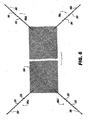
- FIG. 5 shows a presently disclosed embodiment wherein a plurality of fixation devices 306a, 306b, 306c and 306d are engaged to a plurality of locations of a graft 324.
- the fixation devices are 306a, 306b, 306c and 306d are insert molded onto a graft.
- the graft can be used for anterior or posterior repairs wherein the fixation devices 306a, 306b, 306c and 306d can be anchored to the sacrospinous ligament, Cardinal ligament, uterosacral ligament or other tissues and ligament to suspend the graft to support and repair prolapses and enterceles.
- Each fixation device 305a, 306b, 306c and 306d is placed individually at the discretion of the user by drawing the fixation device 306a, 306b, 306c and 306d through ligament of tissue until the desired length of "leg" is achieved.
- a head of the first fixation device 306a is engaged to the delivery instrument 100, driven through a tissue, secured in a catch, positioned in the tissue by withdrawing the delivery instrument 100, and disengaged from the catch.
- the head of the second fixation device 306b is engaged to the delivery instrument 100 and the steps are repeated.
- the above-identified procedure is followed for all additional fixation devices 306c, 306d, etc.
- the graft is centered over the enterocele. In an embodiment, the graft is suspended non-taut.
- FIG. 6 shows a presently disclosed embodiment wherein a plurality of fixation devices 306a, 306b, 306c, and 306d are engaged to graft 324.
- the fixation devices 306a, 306b, 306c and 306d shown in FIG. 5 do not comprise a plurality of barbs 312; rather, the various shafts 300 comprise a plurality of protrusions 313 which allow the user to engage a desired protrusion 313 to the catch 122 to achieve a desired tension.
- the position and the desired tension of the graft 324 is achieved by displacement of the draw of each fixation device 306a, 306b, 306c and 306d through a tissue and/or ligament. Additional draw can create tension in the graft 324.
- the size and shape of the various components of a fixation device 306 and/or sling material 324 can vary for different applications.
- the shaft 300 length can vary from about 1 cm to about 120cm. In an embodiment, the shaft 300 length is greater than about 120cm.
- the longer shaft 300 length enables a second fixation device 306b to be withdrawn from the body after the first placement of the first fixation device 306a in order to be reloaded onto the carrier 124.
- the second fixation device 306b can also be placed into a different location to create a "suture bridge" for approximation or suspension.
- FIG. 7 shows a presently disclosed embodiment wherein the fixation device 306 is a separate unit.
- the fixation device head 328 is sized and shape fitted to the carrier 124 of the delivery instrument 100.
- the circular protrusions 313 allow tissue to pass in one direction and anchors in the opposing direction.
- a backstop 316 is provided to abut against tissue to prevent the fixation device 306 from passing through the tissue.
- the backstop 316 is a circular shape.
- the backstop 316 is a T-shaped protrusion.
- FIG. 7 shows a presently disclosed embodiment wherein a fixation device 306 pierces a first tissue 320 and a second tissue 320 with a single "throw" of the delivery instrument 100.
- the first tissue 320 is pierced by a first throw of the delivery instrument 100 and the second tissue 322 is pierced by a second throw of the delivery instrument 100.
- the head may be pulled in a direction represented by arrow "B" to force the second tissue 322 to approximate to the first tissue 320.
- a rod or a stabilizer can be used in the direction of arrow "C" to approximate the first tissue 320 to the second tissue 322.
- fixation device 306 is secured in place with a button (not show) slid down over the shaft 300 to engage a desired barb 313.
- FIG. 8 shows a lock button 330 incorporated into an embodiment of the presently disclosed fixation device 306.
- the lock button 330 is positioned to receive the carrier 124 and fixation device head 328.
- the lock button 330 has a lock diameter larger than the fixation device head 328 and carrier 124 such that the carrier 124 and fixation device head 328 pass though the lock button 330 freely but is sized to be received by the catch 124.
- the fixation device head 328 is pulled to draw the shaft 300 through the lock hole 330 to engage the locking barbs 313. Further drawing indexes to the next barb 313 tightening the resulting loop. Excess loop is trimmed.
- the fixation device head 328 includes a tip 130 and a shaft 134 coupled to the tip 130, thereby forming a shoulder 132.
- the shaft 134 is coupled to a shaft 300.
- the fixation device head 328 is inserted into the lumen 138 and held by a slight friction fit.
- a user actuates the fixation device deployment mechanism 110 by pushing on the button 117, which via the attachment to the wireform 103 which is attached to the pusher wire 111, moves the coupling 150 along the track 152 concomitantly moving the carrier wire 154, which slidably moves the extendable carrier 124 through the exit port 120.
- the user continues to push the button 117 until the fixation device head 328 enters the catch 122.
- the catch 122 as shown in FIG. 9B , includes openings 170 defined by successive ribs 172.
- the catch 122 receives the fixation device head 328 (coupled to the shaft 300 of the fixation device 306) through opening 170, the ribs 172 deflect slightly to allow the fixation device head 328 to pass through. After the formed shoulder 132 has passed the ribs 172, the ribs 172 spring back to their original position defining the openings 170, and the fixation device head 328 remains captured in the catch 122. The user releases the button 117 and the spring 115 urges the button 117 proximally, moving the pusher wire 111, the coupling 150, the carrier wire 154, and the carrier 124 proximally along with the button 117 to the retracted position.
- the openings 170 are chosen to be smaller in dimension than the formed shoulder 132. This causes the catch 122 to retain the fixation device head 328 because the flat rear surface of the shoulder 132 prevents the fixation device head 328 from passing back through the opening 170.
- the fixation device head 328 may be moved toward an enlarged portion 174 of opening 172.
- the enlarged portion 174 is sized to allow the formed shoulder 132 to pass through without resistance.
- the catch 122 is preferably constructed of thin stainless steel of high temper, such as ANSI 301 full hard.
- the catch 122 may be fabricated by means of stamping, laser machining, or chemical etching. Those skilled in the art will recognize that the catch may be comprise a wide range of materials and remain within the spirit and scope of the present invention; further, those skilled in the art will recognize that the catch may be fabricated by a wide range of methods and remain within the spirit and scope of the present invention.
- the delivery instrument's component materials should be biocompatible.
- the handle 102, the elongate body member 104, and portions of the fixation device head deployment mechanism 110 may be fabricated from extruded, molded, or machined plastic material(s), such as polypropylene, polycarbonate, or glass-filled polycarbonate.
- Other components, for example the fixation device head 328, may be made of stainless steel.
- Other suitable materials will be apparent to those skilled in the art.
- the mechanical components and operation are similar in nature to those disclosed in U.S. Pat. Nos. 5,364,408 and 6,048,351 , each of which is incorporated by reference herein in its entirety.
- the present subject-matter includes, inter alia, the following aspects:
Abstract
Description
- The invention generally is directed to the placement of a fixation device within the body of a patient.
- Conditions such as rertocele, cystocele, enterocele, vaginal prolapse, and protocele involve tissues or organs that have been damaged, prolapsed, weakened or otherwise herniated. A prolapse refers to the slipping of an organ, or organ part, from its normal position. For example, a prolapse of the rectum refers to the protrusion of the rectum through the anus. Rectocele is the prolapse of the rectum into the perineum. A prolapse of the uterus refers to the falling of the uterus into the vagina due to stretching and laxity of its supporting structures. Vaginal vault prolapse refers to the prolapse of the cephalad extreme of the vaginal wall toward, through, and beyond the introitus. Cystocele (i.e., vesicocele) is a hernia formed by the downward and backward displacement of the urinary bladder toward the vaginal orifice, due most commonly to weakening of the musculature during childbirth. However, any abnormal descent of the anterior vaginal wall and bladder base at rest or with strain is considered cystocele. Enterocele is a hernia of the intestine, though the term is also used to refer specifically to herniation of the pelvic peritoneum through the rectouterine pouch (i.e., posterior vaginal, rectovaginal, cul-de-sac, or Douglas' pouch hernia). Proctocele is a prolapse of the mucous coat of the rectum due mostly from relaxation of the sphincter. Treatment of these conditions frequently requires a sling, such as a mesh sling, implanted at the anatomical site-requiring repair.
- Stress urinary incontinence (SUI) primarily affects women and generally is caused by two conditions that may occur independently or in combination, namely, intrinsic sphincter deficiency (ISD) and hypermobility. In ISD, the urinary sphincter valve, located within the urethra, fails to close properly, causing wine to leak out of the urethra during stressful actions. Hypermobility is a condition in which the pelvic floor is distended, weakened, or damaged, causing the bladder neck and proximal urethra to rotate and descend in response to increases in intra-abdominal pressure (e.g., due to sneezing, coughing, straining, etc.), resulting in insufficient response time to promote urethral closure and, consequently, in urine leakage and/or flow.
- Biological factors that may affect hypermobility include: poor endopelvic fascia muscle tone (from, for example, age or limited activity), endopelvic fascia muscle stretch/tear from trauma (e.g., childbirth), endopelvic fascia/arcus tendenious (muscle/ligament) separation (lateral defect), hormone (e.g., estrogen) deficiency, concombinant defects (e.g., cystocele, enterocele, and ureteral prolapse), and vaginal prolapse. Traditional treatment methods include urethra or bladder neck stabilization slings in which a sling is placed under the mid-urethra or bladder neck to provide a platform preventing over distention.
- Slings are traditionally placed under the urethra or bladder neck to provide a urethral platform limiting endopelvic fascia drop while providing compression to the urethral sphincter to improve coaptation. The urethral placement location provides mechanical stability to a less moveable anatomical structure. Bladder neck slings traditionally have been affixed in the desired location using a bone anchoring method. Mid-urethral slings, being placed in a low mobility area, may be placed using an anchorless approach. Recognizing that minimal tension, if any, is necessary, a physician may need only to secure a mid-urethra sling through the endopelvic fascia. The sling in this placement provides a fulcrum about which the pelvic floor will drop (taking advantage of the hypermobility condition of the patient) and a urethral "kink" or higher resistance to obstruct urine flow during high stress conditions.
- A known method for stabilizing organs and tissues within the pelvic region involves the use of bone anchors. Deployment of a bone anchor requires drilling a hole in a bone, either by using a separate drilling instrument or by utilizing the anchor itself as a drilling tool. Bone anchors generally have one or more barbs that project outward to prevent the anchor from exiting the hole. Such anchors generally are not amenable to implantation in soft tissues, since the barbs would tear the soft tissue, causing irritation and/or passage of the anchor back through the tissue.
- Other known methods include making one or more incisions in a patient's abdomen. For example, one method for treating female stress urinary incontinence involves supporting the urethra with an implant anchored in the patient's skin after the implant has been passed through the skin of the patient's abdomen
- Illustrative embodiments according to the invention are directed towards securing a fixation device to a treatment area within the body of a patient such as a human or other mammal. Some embodiments arc directed towards a fixation device sized to be coupled to a delivery instrument for delivering the fixation device to a treatment area within the body by coupling the fixation device to the delivery instrument at a fixation device head of the instrument. Coupling the fixation device to the head of the delivery instrument allows the fixation device to be delivered to a tissue and/or ligament within the body and subsequently secured to that tissue and/or ligament
- In one aspect, the invention relates to an instrument for delivering a fixation device to a tissue comprises a distal portion including a carrier capable of extending from a retracted position to an extended position upon actuation by a user. The carrier comprises a side slot which allows the carrier to receive a fixation device. A shaft of the fixation device passes through the slot of the carrier, and a fixation device head is positioned at a distal end of the carrier. The instrument also comprises a catch for securing the fixation device head once the fixation device head has been driven through the tissue as the carrier moves from the retracted position to the extended position.
- In another aspect, the invention involves a fixation device comprises a head engaged to a shaft. The head and the shaft are sized to be received by an extendable carrier of a delivery instrument, and the head is sized to be secured within a catch of the delivery instrument. A sling can be engaged to the shaft of the fixation device.
- In yet another aspect, the invention features a sling which comprises a first fixation device engaged to a first end of the sling. The first fixation device can comprise a head of the first fixation device engaged to a shaft. The head and the shaft are sized to be received by an extendable carrier of a delivery instrument, and the head is sized to be secured within a catch of the delivery instrument. A plurality of the fixation devices can be engaged to the sling.
- The disclosed embodiments will be further explained with reference to the attached drawings, wherein like structures are referred to by like numerals throughout the several views. The drawings are not necessarily to scale, the emphasis having instead been generally placed upon illustrating the principles of the invention and the disclosed embodiments.
-
FIG. 1A is a schematic plan view of an embodiment of a delivery instrument engaged to an embodiment of a presently disclosed fixation device; -
FIGS. 1B and1C (fixation device not attached) are schematic cross-sectional views of a proximal portion and a distal portion of the delivery instrument ofFIG. 1A ; -
FIG. 2 shows an embodiment of a fixation device engaged to a delivery instrument; - PIG. 3 shows an embodiment wherein the fixation device has passed though a tissue, a fixation device head has been engaged in a catch of a delivery instrument, and the fixation device is being pulled through a tissue and/or a ligament by withdrawing the delivery instrument;
-
FIG. 4 shows an embodiment of a fixation device wherein the fixation device comprises a plurality of barbs; -
FIG. 5 shows an embodiment wherein a plurality of fixation devices are engaged to a graft; -
FIG. 6 shows another embodiment wherein a plurality of fixation devices are engaged to a graft; -
FIG. 7 shows an embodiment of a fixation device comprising a T-shaped protrusion wherein the fixation device is not engaged to a sling material; -
FIG. 8 shows an embodiment of a fixation device and a lock button wherein the lock button engages a protrusion on the fixation device; -
FIG. 9A is a schematic plan view of a fixation device head coupled to a shaft for use in a delivery instrument in accordance with the invention; and -
FIG. 9B is a schematic perspective view of a catch for use with the delivery instrument ofFIG. 1A . - Illustrative embodiments according to the invention are directed towards a fixation device and an instrument and method for securing the fixation device to a treatment area. More specifically, particular illustrative embodiments described herein are directed towards a fixation device sized to be coupled to a delivery instrument, and a method of delivering the fixation device to a treatment area by coupling the fixation device to the delivery instrument at a fixation device head. Coupling the fixation device to the delivery instrument at the fixation device head allows the fixation device to be delivered and secured to a tissue and/or ligament.
- In one embodiment, a method for the placement of a sling material involves engaging a first fixation device to a first end of a sling material and engaging a second fixation device to a second end of the sling material. The fixation device head of the first fixation device is engaged to an extendable carrier of the delivery instrument Next, the fixation device head of the first fixation device is pushed through a tissue and/or ligament and the fixation device head is secured in a catch of the delivery instrument. Once the head of the fixation device is secured in the catch, the delivery instrument is withdrawn from the tissue a desired distance in order to further secure the fixation device to the tissue at a desired tension. The head of the first fixation device head then is disengaged from the delivery instrument.
- Once the first fixation device is secured in the tissue, the head of the second fixation device is engaged to the extendable carrier of the delivery instrument. As such, the second fixation device may be delivered to a second desired location in the same manner as described above. A plurality of fixation devices can be engaged to a sling material and each fixation device is thereby delivered to the treatment area. Any number of fixation devices engaged to a sling material (or any other material) are within the scope of the present invention.
- An embodiment of a
delivery instrument 100 is shown inFIGS. 1A-1C .FIG. 1A depicts adelivery instrument 100 including ahandle 102, anelongate body member 104, and a fixation head deployment mechanism 110. Thedelivery instrument 100 also includes adistal portion 106 and aproximal portion 108. Theelongate body member 104 is mechanically coupled to thehandle 102 at theproximal portion 108 and the delivery components are at least partially disposed within thedistal portion 106 of thedelivery instrument 100. - As shown in
FIG. 1A , afixation device 306 is engaged to thedistal portion 106 of thedelivery instrument 100 by placing thefixation device head 328 in an extendable carrier (shown inFIGS. 1C ). Thecarrier 124 comprises a side slot. When coupling thefixation device 306 to thecarrier 124, theshaft 300 of thefixation device 306 is sized to pass through the side slot and thefixation device head 328 is positioned on top of an opening at a distal end of the carrier. The diameter of thefixation device head 328 is larger than the diameter of a lumen of the carrier. As such, thefixation device head 328 is positioned over the distal opening of the carrier while a portion of theshaft 300 of the fixation device resides within the lumen of the carrier. As such, when the fixation head deployment mechanism 110 is depressed, thecarrier 124 drives thefixation device head 328 through a tissue until thefixation device head 328 is secured in a catch. Once secured in a catch, the carrier retracts to its original position and thus disengages from thefixation device head 328. Once thefixation device head 328 is secured in the catch, thedelivery instrument 100 may be withdrawn a distance to pull thefixation device 306 a desired distance through the tissue. Finally, thefixation device head 328 is disengaged from the carrier Once the fixation device has been successfully placed in a tissue. An embodiment of these components will be shown in detail inFIGS. 1B and1C . - The
handle 102 of thedelivery instrument 100 could take a variety of forms, for example, thehandle 102 could be one of the types used with Boston Scientific Corporation suturing systems, in particular the Capio® Push & Catch suturing system. Generally, the fixation device deployment mechanism 110 extends longitudinally through theelongate body member 104 to thedistal portion 106 of thedelivery instrument 100, where the fixation device head deployment mechanism 110 is coupled to a carrier 124 (FIG. 1C ). The fixation device head deployment mechanism 110 moves thecarrier 124 between a retracted position and a extended position. The fixation device deployment mechanism 110 is shown in greater detail inFIGS. 1B and1C . - Referring to
FIG. 1B , theproximal portion 108 of thedelivery instrument 100 includes thehandle 102, theelongate body member 104, and the fixation device deployment mechanism 110. The fixation device deployment mechanism 110 includes an actuator 112 (button 117, shaft 116), abearing 118, abutton end 119, and ahole 121. The bearing 118 rides along acylindrical surface 105 that is formed by the inside diameter of theelongate body member 104. Awireform 103 is inserted into thehole 121, coupling it to theactuator button 117. Aspring 115 encircles thewireform 103, abuts thebutton end 119, and is compressed between thebutton end 119 and a spring washer 113. The spring washer 113 is seated upon acenter tube 107. Thecenter tube 107 is housed by thecylindrical surface 105 and is constrained in thedistal portion 106, Apusher wire 111 is attached to thewireform 103 by means of a weld, a coupling, adhesive or other means, and is slidably disposed within aguidance sleeve 109, thesleeve 109 being disposed within acylindrical surface 123 formed by the inside diameter of thecenter tube 107. In an embodiment, thepusher wire 111 is constructed of nitinol, so chosen for its combination of properties that allow for bendability and high column strength when constrained. Nitinol is a nickel-titanium alloy. Those skilled in the art will recognize that a wire made of various materials are within the spirit and scope of the present invention. - Referring to
FIG. 1C , thedistal portion 106 of thedelivery instrument 100 ofFIG. 1A includes theelongate body member 104, the fixation device deployment mechanism 110, anarticulation mechanism 114, acurved portion 126, and acatch 122. Referring again to the fixation device deployment mechanism 110, thepusher wire 111 is attached by welding or other means to acoupling 150, which is slidably disposed within atrack 152. Thecoupling 150 is attached to acarrier wire 154, which by virtue of its attachment to thecoupling 150 is also slidably disposed within thetrack 152. Thecarrier wire 154 is mechanically coupled to anextendable carrier 124 by means of a weld, a coupling, adhesives, or other means. Thecoupling 150 abuts abackstop washer 156 that is slidably disposed about thepusher wire 111 and is contained within apocket 160 that includes aback wall 162, against which thebackstop washer 156 rests. Thetrack 152 terminates distally in apocket 164 that includes awall 166. Adownstop washer 158 is slidably disposed about thecarrier wire 154 and constrained within thepocket 164. - in some embodiments, the
delivery instrument 100 may include thearticulation mechanism 114. Thearticulation mechanism 114 is disposed in theelongate body member 104 proximate the distal portion 106 (FIG. 1C ). Thearticulation mechanism 114 facilitates the rotation (in the directions indicated by arrow 182) and positioning of thedistal end 106 of thedelivery instrument 100. In addition, theelongate body 104 can be substantially linear or may include one or more bends. Thearticulation mechanism 114 and/or bend(s) can facilitate access to deep and/or difficult to reach areas within the patient. -
FIG. 1C shows adistal opening 125 of thecarrier 124. As discussed above, the carrier comprises a side slot which begins at thedistal opening 125. In addifion, thecurved section 126 of the distal end comprises a slot 127 (shown inFIG. 3 ) which aligns with the side slot of thecarrier 124. Aligning the slot of the carrier with the slot of thecurved section 126 allows theshaft 300 of the fixation device to reside within a portion of the carrier while thefixation device head 328 rests on top of thedistal opening 125 of the carrier (as shown inFIG.1A andFIG. 2 ). -
FIG. 2 shows a presently disclosed embodiment of adelivery instrument 100 engaged to afixation device 306. Thefixation device 306 is engaged to thedelivery instrument 100 by inserting thefixation device head 328 into anextendable carrier 124. As described above in relation toFIGS. 1A-1C , theextendable carrier 124 may be in a retracted position or an extended position. As shown inFIG. 2 , theextendable carrier 124 is in a retracted position. - As shown in
FIG. 2 , an embodiment of thefixation device 306 comprises ashaft 300 which runs from thefixation device head 328 and ends with the beginning of asling material 324. In an embodiment, thesling material 324 is a mesh. In an embodiment, thesling material 324 is a graft. In an embodiment, thesling material 324 may comprise a drug. Those skilled in the art will recognize that various other materials are within the spirit and scope of the present invention. - When the
fixation device head 328 is coupled to thedelivery instrument 100, the shoulder of thefixation device head 328 rests on the front edge of theextendable carrier 124, while theflexible shaft 300 of thefixation device 306 slides into theextendable carrier 124 through a slot and exits by a side port. The length of theflexible shaft 306 can vary depending on the need to exit the body for reloading for securing anadditional fixation device 306. - In the embodiment shown in
FIG. 2 , a first and asecond protrusion 302 extend from theflexible shaft 300 to encapsulate the sling material (i.e., a mesh or graft) and act as a leading edge. In an embodiment, the leading edge is stiffer than the sling material and angled to provide support to keep the sling material width extended yet collapsible to follow theflexible shaft 300 through a ligament and/ortissue 310. The ends of theleading edge 302 can also act as a barb for anchoring thefixation device 306 in place. - In an embodiment, the
flexible shaft 300 extends through the sling material and act as a backbone orsupport segment 304. Thebackbone segment 304 provides strength to thesling material 324 to prevent thesling material 324 from unraveling as thefixation device 306 is pulled through a tissue and/orligament 310. - In an embodiment, the
sling material 324 comprises a plurality oftangs 308. Thetangs 308 engage the tissue and/orligament 310 in order to help secure thefixation device 306 to the tissue and/orligament 310. - In an embodiment, the
fixation device 306 comprises a medical grade, implantable polypropylene. In an embodiment, thefixation device 306 comprises a bio-absorbable material. Those skilled in the art will recognize that various materials are within the spirit and scope of the present invention. -
FIG. 2 shows an embodiment wherein thedelivery instrument 100 comprises theextendable carrier 124 in a retracted orientation. By engaging the fixation device deployment mechanism 110 (discussed above in relation toFIGS. 1A-1C ), theextendable carrier 124 is extended full to allow thefixation device head 328 to pierce ligament or tissue and be received in thecatch 122. As will be shown below, the pointedfixation device head 328 spreads the slot of thecatch 122 as it passes into thecatch 122. The slot then narrows as theextendable carrier 124 retracts, trapping the head by its wider shoulder within the catch 122 (seeFIGS. 9A and 9B ). -
FIG. 3 shows an embodiment of the presently discloseddelivery instrument 100 wherein thefixation device head 328 has passed through atissue 310 and is now secured in thecatch 122. Once thefixation device head 328 is retained in the catch of thedelivery instrument 100, thedelivery instrument 100 is pulled away from the treatment area in the general direction of arrow "A". As thedelivery instrument 100 is withdrawn from the tissue and/orligament 310, thefixation device 306 is drawn through the ligament and/ortissue 310. Thefixation device 306 is drawn through the ligament/tissue until a desired length of fixation device is achieved for the proper suspension and/or tension. - In an embodiment, the
fixation device 306 may be cut with a cutting instrument to remove any unwanted material. Thefixation device 306 and the portion of the cut fixation device is retrieved external to the body through the exit port of thecatch 122. In an embodiment, thedelivery instrument 100 can be used for placement of additional fixation devices or needled sutures in the same patient. -
FIG. 4 shows a presently disclosed embodiment wherein afirst fixation device 306a is engaged to a first end of asling 324 and asecond fixation device 306b is engaged to a second end of asling 324. In an embodiment, afixation device 306 is insert molded onto thesling material 324. - In an embodiment, the sling is an incontinence sling. Those skilled in the art will recognize that any type of sling is within the spirit and scope of the present invention.
- In an embodiment, the presently disclosed
delivery instrument 100 is used to place the sling ends through Cooper's ligament in a manner similarly described above and repeated on the contra lateral side. In an embodiment, the sling can be threaded in and out of the transobturators using adelivery instrument 100 via a single incision vaginal approach using a fixation device having a longer flexible shaft as shown inFIG. 4 , for tensioning afterwards, through a mid-line incision. - In an embodiment as shown in
FIG. 4 , a plurality ofbarbs 312 are positioned along theshaft 300 of eachfixation device barbs 312 positioned along theflexible shaft 300. -
FIG. 5 shows a presently disclosed embodiment wherein a plurality offixation devices graft 324. In an embodiment, the fixation devices are 306a, 306b, 306c and 306d are insert molded onto a graft. Those skilled in the art will recognize that various processes may be used to engage afixation device 306 to the graft and remain within the spirit and scope of the present invention. - The graft can be used for anterior or posterior repairs wherein the
fixation devices - Each
fixation device fixation device first fixation device 306a is engaged to thedelivery instrument 100, driven through a tissue, secured in a catch, positioned in the tissue by withdrawing thedelivery instrument 100, and disengaged from the catch. Next, the head of thesecond fixation device 306b is engaged to thedelivery instrument 100 and the steps are repeated. The above-identified procedure is followed for alladditional fixation devices - In an embodiment, the graft is centered over the enterocele. In an embodiment, the graft is suspended non-taut.
-
FIG. 6 shows a presently disclosed embodiment wherein a plurality offixation devices graft 324. In comparison to thefixation devices FIG. 5 , thefixation devices barbs 312; rather, thevarious shafts 300 comprise a plurality ofprotrusions 313 which allow the user to engage a desiredprotrusion 313 to thecatch 122 to achieve a desired tension. As such, the position and the desired tension of thegraft 324 is achieved by displacement of the draw of eachfixation device graft 324. - The size and shape of the various components of a
fixation device 306 and/orsling material 324 can vary for different applications. Theshaft 300 length can vary from about 1 cm to about 120cm. In an embodiment, theshaft 300 length is greater than about 120cm. Thelonger shaft 300 length enables asecond fixation device 306b to be withdrawn from the body after the first placement of thefirst fixation device 306a in order to be reloaded onto thecarrier 124. Thesecond fixation device 306b can also be placed into a different location to create a "suture bridge" for approximation or suspension. -
FIG. 7 shows a presently disclosed embodiment wherein thefixation device 306 is a separate unit. Thefixation device head 328 is sized and shape fitted to thecarrier 124 of thedelivery instrument 100. Thecircular protrusions 313 allow tissue to pass in one direction and anchors in the opposing direction. Abackstop 316 is provided to abut against tissue to prevent thefixation device 306 from passing through the tissue. In an embodiment, thebackstop 316 is a circular shape. In an embodiment, thebackstop 316 is a T-shaped protrusion. Those skilled in the art will recognize that any a backstop of any shape which prevents the fixation device from passing through the tissue is within the spirit and scope of the present invention. -
FIG. 7 shows a presently disclosed embodiment wherein afixation device 306 pierces afirst tissue 320 and asecond tissue 320 with a single "throw" of thedelivery instrument 100. In an embodiment, thefirst tissue 320 is pierced by a first throw of thedelivery instrument 100 and thesecond tissue 322 is pierced by a second throw of thedelivery instrument 100. The head may be pulled in a direction represented by arrow "B" to force thesecond tissue 322 to approximate to thefirst tissue 320. In an embodiment, a rod or a stabilizer can be used in the direction of arrow "C" to approximate thefirst tissue 320 to thesecond tissue 322. - In an embodiment, the
fixation device 306 is secured in place with a button (not show) slid down over theshaft 300 to engage a desiredbarb 313. -
FIG. 8 shows alock button 330 incorporated into an embodiment of the presently disclosedfixation device 306. In an embodiment, thelock button 330 is positioned to receive thecarrier 124 andfixation device head 328. Thelock button 330 has a lock diameter larger than thefixation device head 328 andcarrier 124 such that thecarrier 124 andfixation device head 328 pass though thelock button 330 freely but is sized to be received by thecatch 124. To lock, thefixation device head 328 is pulled to draw theshaft 300 through thelock hole 330 to engage the lockingbarbs 313. Further drawing indexes to thenext barb 313 tightening the resulting loop. Excess loop is trimmed. - Referring to
FIG. 9A , in one embodiment, thefixation device head 328 includes atip 130 and ashaft 134 coupled to thetip 130, thereby forming ashoulder 132. Theshaft 134 is coupled to ashaft 300. Thefixation device head 328 is inserted into the lumen 138 and held by a slight friction fit. - Referring again to
FIGS. 1B and1C , in operation, a user (such as a physician or other medical personnel) actuates the fixation device deployment mechanism 110 by pushing on thebutton 117, which via the attachment to thewireform 103 which is attached to thepusher wire 111, moves thecoupling 150 along thetrack 152 concomitantly moving thecarrier wire 154, which slidably moves theextendable carrier 124 through the exit port 120. The user continues to push thebutton 117 until thefixation device head 328 enters thecatch 122. Thecatch 122, as shown inFIG. 9B , includesopenings 170 defined bysuccessive ribs 172. Thecatch 122 receives the fixation device head 328 (coupled to theshaft 300 of the fixation device 306) throughopening 170, theribs 172 deflect slightly to allow thefixation device head 328 to pass through. After the formedshoulder 132 has passed theribs 172, theribs 172 spring back to their original position defining theopenings 170, and thefixation device head 328 remains captured in thecatch 122. The user releases thebutton 117 and thespring 115 urges thebutton 117 proximally, moving thepusher wire 111, thecoupling 150, thecarrier wire 154, and thecarrier 124 proximally along with thebutton 117 to the retracted position. As theextendable carrier 124 moves back to the retracted position, thefixation device head 328 slides out of the carrier. Theopenings 170 are chosen to be smaller in dimension than the formedshoulder 132. This causes thecatch 122 to retain thefixation device head 328 because the flat rear surface of theshoulder 132 prevents thefixation device head 328 from passing back through theopening 170. When it is necessary to remove thefixation device head 328 from thecatch 122, thefixation device head 328 may be moved toward anenlarged portion 174 ofopening 172. Theenlarged portion 174 is sized to allow the formedshoulder 132 to pass through without resistance. Thecatch 122 is preferably constructed of thin stainless steel of high temper, such as ANSI 301 full hard. Thecatch 122 may be fabricated by means of stamping, laser machining, or chemical etching. Those skilled in the art will recognize that the catch may be comprise a wide range of materials and remain within the spirit and scope of the present invention; further, those skilled in the art will recognize that the catch may be fabricated by a wide range of methods and remain within the spirit and scope of the present invention. - The delivery instrument's component materials should be biocompatible. For example, the
handle 102, theelongate body member 104, and portions of the fixation device head deployment mechanism 110 may be fabricated from extruded, molded, or machined plastic material(s), such as polypropylene, polycarbonate, or glass-filled polycarbonate. Other components, for example thefixation device head 328, may be made of stainless steel. Other suitable materials will be apparent to those skilled in the art. Additionally, the mechanical components and operation are similar in nature to those disclosed inU.S. Pat. Nos. 5,364,408 and6,048,351 , each of which is incorporated by reference herein in its entirety. - Certain embodiments according to the invention have been disclosed. These embodiments are illustrative of, and not limiting on, the invention. Other embodiments, as well as various modifications and combinations of the disclosed embodiments, arc possible and are within the scope of this disclosure.
- The present subject-matter includes, inter alia, the following aspects:
- 1. An instrument for delivering a fixation device to tissue of a patient, comprising:
- a distal portion including a carrier capable of extending from a retracted position to an extended position upon actuation by a user, the carrier comprising a side slot which allows the carrier to receive a fixation device, a shaft of the fixation device passing through the slot of the carrier, a head of the fixation device being positioned at a distal end of the carrier; and
- a catch for securing the head of the fixation device once the head has been driven through the tissue as the carrier moves from the retracted position to the extended position.
- 2. The instrument of aspect 1 wherein the fixation device is engaged to a mesh material.
- 3. The instrument of aspect 2 wherein the mesh material comprises a plurality of tangs.
- 4. The instrument of aspect 2 wherein the shaft passes through the mesh material.
- 5. The instrument of aspect 1 wherein the shaft comprises a plurality of circular protrusions for engaging a lock button.
- 6. The instrument of aspect 1 wherein the fixation device is engaged to a graft.
- 7. The instrument of aspect 1 wherein the shaft comprises a plurality of barbs.
- 8. The instrument of aspect 1 wherein the fixation device terminates in a T-shaped protrusion.
- 9. The instrument of aspect 1 further comprising a fixation device deployment mechanism which is engaged to the carrier and which drives the carrier from a retracted position to an extendable position when the fixation device deployment mechanism is depressed by a user.
- 10. A fixation device, comprising:
- a fixation device head engaged to a shaft, the head and shaft being sized to be received by an extendable carrier of a delivery instrument, the head being sized to be secured within a catch of the delivery instrument; and
- a sling material engaged to the shaft of the fixation device to secure the fixation device to tissue of a patient.
- 11. The fixation device of aspect 10 wherein the sling material comprises a mesh material.
- 12. The fixation device of
aspect 11 wherein the mesh material comprises a plurality of tangs. - 13. The fixation device of aspect 10 wherein the shaft passes through the sling material.
- 14. The fixation device of aspect 10 wherein the shaft comprises a plurality of barbs.
- 15. The fixation device of aspect 10 wherein the shaft comprises a plurality of circular protrusions to be engaged by a lock button.
- 16. A sling, comprising:
- a first fixation device engaged to a first end of the sling, the first fixation device comprising a first fixation device head engaged to a shaft, the first fixation device head and the shaft being sized to be received by an extendable carrier of a delivery instrument, the first fixation device head being sized to be secured within a catch of the delivery instrument.
- 17. The sling of aspect 16 further comprising a second fixation device engaged to a second end of the sling, the second fixation device comprising a second fixation device head engaged to a shaft, the second fixation device head and the shaft being sized to be received by an extendable carrier of a delivery instrument, the second fixation device head being sized to be secured within a catch of the delivery instrument.
- 18. The sling of aspect 16 wherein the first fixation device comprises a plurality of barbs along the shaft of the fixation device.
- 19. The sling of aspect 16 wherein the first fixation device head comprises a pointed tip.
- 20. The sling of aspect 16 further comprising a plurality of fixation device are engaged to the sling.
Claims (15)
- A fixation device, comprising:a fixation device head engaged to a flexible shaft, the head and flexible shaft being sized to be received by an extendable carrier of a delivery instrument, the head being sized to be secured within a catch of the delivery instrument, the flexible shaft including a first protrusion and a second protrusion each extending from the flexible shaft and each being angled relative to a longitudinal axis of the flexible shaft; anda sling material engaged to the flexible shaft of the fixation device and including a distal end having an angle substantially equal to the angle formed by the first and second protrusions of the flexible shaft, the first and second protrusions collectively encapsulating-a the distal end of the sling material.
- The fixation device of claim 1, wherein the sling material comprises a mesh material.
- The fixation device of claim 2, wherein the mesh material comprises a plurality of tangs.
- The fixation device of claim 1, wherein the flexible shaft comprises a plurality of barbsand/or wherein the flexible shaft comprises a plurality of circular protrusions to be engaged by a lock button.
- The fixation device of claim 1, wherein the flexible shaft extends into at least a portion of the sling material forming a support segment to provide strength to the sling material.
- The fixation device of claim 1, wherein the distal edge is movable between a first width and a second width less than the first width, the distal edge being biased to the first width.
- A sling, comprising:a first fixation device engaged to a first end of the sling, the first fixation device comprising a first fixation device head engaged to a flexible shaft and a first protrusion and a second protrusion extending from the flexible shaft, the first and second protrusions each being angled relative to a longitudinal axis of the flexible shaft and collectively encapsulating a distal end of the sling material to form a distal edge of the sling, the distal edge being movable between a first width and a second width less than the first width, the distal edge being biased to the first width, the first fixation device head and the flexible shaft being sized to be received by an extendable carrier of a delivery instrument, the first fixation device head being sized to be secured within a catch of the delivery instrument, the flexible shaft of the first fixation device extending into at least a portion of the sling material forming a support segment to provide strength to the sling material.
- The sling of claim 7, further comprising a second fixation device engaged to a second end of the sling, the second fixation device comprising a second fixation device head engaged to a flexible shaft, the second fixation device head and the flexible shaft being sized to be received by an extendable carrier of a delivery instrument, the second fixation device head being sized to be secured within a catch of the delivery instrument and/or wherein the first fixation device comprises a plurality of barbs along the flexible shaft of the fixation device and/or wherein the first fixation device head comprises a pointed tip and/or further comprising a plurality of fixation devices engaged to the sling.
- An instrument for delivering a fixation device to tissue of a patient, comprising:an elongate body member;a deployment mechanism disposed at a distal portion of the elongate body member, the deployment mechanism including a carrier capable of extending from a retracted position to an extended position, the carrier comprising a side slot for receiving a portion of a fixation device, the fixation device including a head engaged to a flexible shaft, a sling material engaged to the flexible shaft of the fixation device, and a first and second protrusion extending from the flexible shaft, the first and second protrusions each being angled relative to a longitudinal axis of the flexible shaft and collectively encapsulating a distal end of the sling material, the distal portion of the elongate body member having a slot that is in alignment with the side slot of the carrier when the carrier is in its retracted position; anda catch disposed on the elongate body member, the catch defining at least one opening for receiving the carrier holding the fixation device, retaining the head of the fixation device within the catch, and allowing the carrier to retract, such that the fixation device is released from the side slot of the carrier when the carrier is retracted from the catch.
- The instrument of claim 9, wherein the sling material comprises a mesh material, wherein the mesh material preferably comprises a plurality of tangs and/or wherein the sling material comprises a graft.
- The instrument of claim 9, wherein the flexible shaft comprises a plurality of circular protrusions for engaging a lock button.
- The instrument of claim 9, wherein the flexible shaft comprises a plurality of barbs and/or wherein the flexible shaft extends into at least a portion of the sling material forming a support segment to provide strength to the sling material.
- The instrument of claim 9, wherein the fixation device terminates in a T-shaped protrusion and/or wherein the fixation device head is sized to be received by the carrier of the deployment mechanism.
- The instrument of claim 9, wherein the slot of the distal portion of the elongate body member is sized to allow a portion of the flexible shaft of the fixation device to extend through the slot of the distal portion from the carrier to an area external to the distal portion of the elongate body member.
- A fixation device, comprising:a fixation device head engaged to a shaft, the head and shaft being sized to be received by an extendable carrier of a delivery instrument, the head being sized to be secured within a catch of the delivery instrument; anda sling material engaged to the shaft of the fixation device to secure the fixation device to tissue of a patient.
Applications Claiming Priority (2)
| Application Number | Priority Date | Filing Date | Title |
|---|---|---|---|
| US11/331,777 US9144483B2 (en) | 2006-01-13 | 2006-01-13 | Placing fixation devices |
| EP07716311A EP1978891B1 (en) | 2006-01-13 | 2007-01-05 | Placing fixation devices |
Related Parent Applications (2)
| Application Number | Title | Priority Date | Filing Date |
|---|---|---|---|
| EP07716311A Division EP1978891B1 (en) | 2006-01-13 | 2007-01-05 | Placing fixation devices |
| EP07716311.1 Division | 2007-01-05 |
Publications (3)
| Publication Number | Publication Date |
|---|---|
| EP2305128A2 true EP2305128A2 (en) | 2011-04-06 |
| EP2305128A3 EP2305128A3 (en) | 2011-05-04 |
| EP2305128B1 EP2305128B1 (en) | 2015-11-04 |
Family
ID=38122322
Family Applications (2)
| Application Number | Title | Priority Date | Filing Date |
|---|---|---|---|
| EP07716311A Active EP1978891B1 (en) | 2006-01-13 | 2007-01-05 | Placing fixation devices |
| EP10189230.5A Active EP2305128B1 (en) | 2006-01-13 | 2007-01-05 | Placing fixation devices |
Family Applications Before (1)
| Application Number | Title | Priority Date | Filing Date |
|---|---|---|---|
| EP07716311A Active EP1978891B1 (en) | 2006-01-13 | 2007-01-05 | Placing fixation devices |
Country Status (6)
| Country | Link |
|---|---|
| US (1) | US9144483B2 (en) |
| EP (2) | EP1978891B1 (en) |
| JP (2) | JP5232655B2 (en) |
| CA (1) | CA2636215C (en) |
| DE (1) | DE602007011204D1 (en) |
| WO (1) | WO2007087132A1 (en) |
Families Citing this family (103)
| Publication number | Priority date | Publication date | Assignee | Title |
|---|---|---|---|---|
| US6641525B2 (en) | 2001-01-23 | 2003-11-04 | Ams Research Corporation | Sling assembly with secure and convenient attachment |
| US8109866B2 (en) * | 2005-04-26 | 2012-02-07 | Ams Research Corporation | Method and apparatus for prolapse repair |
| US20100094079A1 (en) | 2005-06-21 | 2010-04-15 | Ams Research Corporation | Method and Apparatus for Securing a Urethral Sling to Pubic Bone |
| US8864650B2 (en) | 2005-06-21 | 2014-10-21 | Ams Research Corporation | Methods and apparatus for securing a urethral sling to a pubic bone |
| EP3533416A1 (en) | 2005-07-25 | 2019-09-04 | Boston Scientific Limited | Pelvic floor repair system |
| US8535217B2 (en) | 2005-07-26 | 2013-09-17 | Ams Research Corporation | Methods and systems for treatment of prolapse |
| US7878970B2 (en) | 2005-09-28 | 2011-02-01 | Boston Scientific Scimed, Inc. | Apparatus and method for suspending a uterus |
| US9144483B2 (en) | 2006-01-13 | 2015-09-29 | Boston Scientific Scimed, Inc. | Placing fixation devices |
| CN101420909B (en) * | 2006-02-16 | 2011-08-03 | Ams研究公司 | Surgical articles and methods for treating pelvic conditions |
| US9078727B2 (en) * | 2006-03-16 | 2015-07-14 | Boston Scientific Scimed, Inc. | System and method for treating tissue wall prolapse |
| US8900324B2 (en) * | 2006-03-16 | 2014-12-02 | Boston Scientific Scimed, Inc. | System and method for treating tissue wall prolapse |
| WO2007137226A2 (en) | 2006-05-19 | 2007-11-29 | Ams Research Corporation | Method and articles for treatment of stress urinary incontinence |
| CA2654966A1 (en) | 2006-06-16 | 2007-12-27 | Ams Research Corporation | Surgical implants and tools for treating pelvic conditions |
| WO2007149555A2 (en) * | 2006-06-22 | 2007-12-27 | Ams Research Corporation | Adjustable tension incontinence sling assemblies |
| JP4718636B2 (en) * | 2006-07-25 | 2011-07-06 | エーエムエス リサーチ コーポレイション | Surgical apparatus and method for treating pelvic disease |
| US8702729B2 (en) * | 2006-10-13 | 2014-04-22 | Boston Scientific Scimed, Inc. | Placing multiple sutures |
| US8951185B2 (en) | 2007-10-26 | 2015-02-10 | Ams Research Corporation | Surgical articles and methods for treating pelvic conditions |
| EP2086465B1 (en) | 2006-10-26 | 2012-04-25 | AMS Research Corporation | Surgical articles for treating pelvic conditions |
| CN101528139B (en) | 2006-10-26 | 2014-10-01 | Ams研究公司 | Surgical articles for treating pelvic conditions |
| CA2668699C (en) | 2006-11-06 | 2014-01-07 | Caldera Medical, Inc. | Implants and procedures for treatment of pelvic floor disorders |
| KR101494190B1 (en) | 2007-07-27 | 2015-02-17 | 에이엠에스 리서치 코포레이션 | Pelvic floor treatments and related tools and implants |
| CN101842060B (en) | 2007-09-21 | 2014-07-16 | Ams研究公司 | Pelvic floor treatments and related tools and implants |
| US20100298630A1 (en) * | 2007-12-07 | 2010-11-25 | Shawn Michael Wignall | Pelvic floor treatments and related tools and implants |
| US8430807B2 (en) | 2007-12-28 | 2013-04-30 | Boston Scientific Scimed, Inc. | Devices and methods for treating pelvic floor dysfunctions |
| US9393002B2 (en) | 2008-02-18 | 2016-07-19 | Covidien Lp | Clip for implant deployment device |
| US8758373B2 (en) | 2008-02-18 | 2014-06-24 | Covidien Lp | Means and method for reversibly connecting a patch to a patch deployment device |
| US9044235B2 (en) | 2008-02-18 | 2015-06-02 | Covidien Lp | Magnetic clip for implant deployment device |
| US9034002B2 (en) | 2008-02-18 | 2015-05-19 | Covidien Lp | Lock bar spring and clip for implant deployment device |
| US8317808B2 (en) | 2008-02-18 | 2012-11-27 | Covidien Lp | Device and method for rolling and inserting a prosthetic patch into a body cavity |
| US8808314B2 (en) | 2008-02-18 | 2014-08-19 | Covidien Lp | Device and method for deploying and attaching an implant to a biological tissue |
| AU2009215269B2 (en) | 2008-02-18 | 2013-01-31 | Covidien Lp | A device and method for deploying and attaching a patch to a biological tissue |
| US9393093B2 (en) | 2008-02-18 | 2016-07-19 | Covidien Lp | Clip for implant deployment device |
| US9833240B2 (en) | 2008-02-18 | 2017-12-05 | Covidien Lp | Lock bar spring and clip for implant deployment device |
| US9301826B2 (en) | 2008-02-18 | 2016-04-05 | Covidien Lp | Lock bar spring and clip for implant deployment device |
| US9398944B2 (en) | 2008-02-18 | 2016-07-26 | Covidien Lp | Lock bar spring and clip for implant deployment device |
| US20090240102A1 (en) * | 2008-03-14 | 2009-09-24 | Ajay Rane | Apparatus and method for repairing vaginal reconstruction |
| US9017382B2 (en) * | 2008-05-19 | 2015-04-28 | Ams Research Corporation | Collapsible tissue anchor device and method |
| US8727963B2 (en) | 2008-07-31 | 2014-05-20 | Ams Research Corporation | Methods and implants for treating urinary incontinence |
| WO2010027796A1 (en) | 2008-08-25 | 2010-03-11 | Ams Research Corporation | Minimally invasive implant and method |
| US9017243B2 (en) | 2008-08-25 | 2015-04-28 | Ams Research Corporation | Minimally invasive implant and method |
| EP2792307B1 (en) | 2008-10-20 | 2017-10-04 | Covidien LP | A device for attaching a patch to a biological tissue |
| EP3424437A1 (en) | 2008-10-27 | 2019-01-09 | Boston Scientific Scimed, Inc. | Surgical needle and anchor system with retractable features |
| US8758220B2 (en) * | 2009-01-05 | 2014-06-24 | Caldera Medical, Inc. | Implants and procedures for supporting anatomical structures for treating conditions such as pelvic organ prolapse |
| WO2010093421A2 (en) | 2009-02-10 | 2010-08-19 | Ams Research Corporation | Surgical articles and methods for treating urinary incontinence |
| US9125716B2 (en) * | 2009-04-17 | 2015-09-08 | Boston Scientific Scimed, Inc. | Delivery sleeve for pelvic floor implants |
| EP3508144B1 (en) | 2009-08-17 | 2021-04-07 | Covidien LP | Patch deployment device |
| WO2011021083A1 (en) | 2009-08-17 | 2011-02-24 | PolyTouch Medical, Inc. | Articulating patch deployment device and method of use |
| US9414902B2 (en) | 2009-11-04 | 2016-08-16 | Boston Scientific Scimed, Inc. | Method for treating prolapse and incontinence |
| US9364308B2 (en) | 2009-12-30 | 2016-06-14 | Astora Women's Health, Llc | Implant systems with tensioning feedback |
| WO2011082220A1 (en) | 2009-12-30 | 2011-07-07 | Ams Research Corporation | Elongate implant system and method for treating pelvic conditions |
| CA2785830A1 (en) | 2009-12-30 | 2011-07-07 | Ams Research Corporation | Implantable sling systems and methods |
| US9393091B2 (en) | 2009-12-31 | 2016-07-19 | Astora Women's Health, Llc | Suture-less tissue fixation for implantable device |
| US9820730B2 (en) * | 2010-02-04 | 2017-11-21 | Boston Scientific Scimed, Inc. | Tension adapter for medical device |
| US9445881B2 (en) | 2010-02-23 | 2016-09-20 | Boston Scientific Scimed, Inc. | Surgical articles and methods |
| EP3721832B1 (en) | 2010-02-23 | 2023-03-29 | Boston Scientific Scimed, Inc. | Surgical articles for treating incontinence |
| EP2563239B1 (en) | 2010-04-30 | 2018-01-31 | Boston Scientific Scimed, Inc. | Delivering pelvic floor repair implants |
| US10028813B2 (en) | 2010-07-22 | 2018-07-24 | Boston Scientific Scimed, Inc. | Coated pelvic implant device and method |
| US8911348B2 (en) | 2010-09-02 | 2014-12-16 | Boston Scientific Scimed, Inc. | Pelvic implants and methods of implanting the same |
| US9271754B2 (en) | 2010-12-16 | 2016-03-01 | Boston Scientific Scimed, Inc. | Movable curved needle for delivering implants and methods of delivering implants |
| US9572648B2 (en) | 2010-12-21 | 2017-02-21 | Justin M. Crank | Implantable slings and anchor systems |
| US9381075B2 (en) | 2011-01-31 | 2016-07-05 | Boston Scientific Scimed, Inc. | Deflection member for delivering implants and methods of delivering implants |
| US9125717B2 (en) | 2011-02-23 | 2015-09-08 | Ams Research Corporation | Implant tension adjustment system and method |
| US20140179987A1 (en) * | 2011-03-25 | 2014-06-26 | Boston Scientific Scimed, Inc. | Kit for Placing Fixation Devices |
| US8808162B2 (en) | 2011-03-28 | 2014-08-19 | Ams Research Corporation | Implants, tools, and methods for treatment of pelvic conditions |
| US9089393B2 (en) | 2011-03-28 | 2015-07-28 | Ams Research Corporation | Implants, tools, and methods for treatment of pelvic conditions |
| US9492259B2 (en) | 2011-03-30 | 2016-11-15 | Astora Women's Health, Llc | Expandable implant system |
| US9636201B2 (en) | 2011-05-12 | 2017-05-02 | Boston Scientific Scimed, Inc. | Delivery members for delivering an implant into a body of a patient |
| US10058240B2 (en) | 2011-06-29 | 2018-08-28 | Boston Scientific Scimed, Inc. | Systems, implants, tools, and methods for treatments of pelvic conditions |
| US20130006049A1 (en) | 2011-06-30 | 2013-01-03 | Alexander James A | Implants, tools, and methods for treatments of pelvic conditions |
| US9351723B2 (en) | 2011-06-30 | 2016-05-31 | Astora Women's Health, Llc | Implants, tools, and methods for treatments of pelvic conditions |
| EP2734148B1 (en) | 2011-07-22 | 2019-06-05 | Boston Scientific Scimed, Inc. | Pelvic implant system |
| US9414903B2 (en) * | 2011-07-22 | 2016-08-16 | Astora Women's Health, Llc | Pelvic implant system and method |
| US9492191B2 (en) | 2011-08-04 | 2016-11-15 | Astora Women's Health, Llc | Tools and methods for treatment of pelvic conditions |
| US20130035555A1 (en) | 2011-08-05 | 2013-02-07 | Alexander James A | Systems, implants, tools, and methods for treatment of pelvic conditions |
| US10098721B2 (en) | 2011-09-01 | 2018-10-16 | Boston Scientific Scimed, Inc. | Pelvic implant needle system and method |
| US9345472B2 (en) | 2011-09-02 | 2016-05-24 | Boston Scientific Scimed, Inc. | Multi-arm tool for delivering implants and methods thereof |
| USD721175S1 (en) | 2011-09-08 | 2015-01-13 | Ams Research Corporation | Backers for surgical indicators |
| USD721807S1 (en) | 2011-09-08 | 2015-01-27 | Ams Research Corporation | Surgical indicators |
| USD736382S1 (en) | 2011-09-08 | 2015-08-11 | Ams Research Corporation | Surgical indicator with backers |
| US9168120B2 (en) | 2011-09-09 | 2015-10-27 | Boston Scientific Scimed, Inc. | Medical device and methods of delivering the medical device |
| EP2757998A4 (en) | 2011-09-22 | 2015-05-06 | Ams Res Corp | Pelvic implant and treatment method |
| US10265152B2 (en) | 2011-10-13 | 2019-04-23 | Boston Scientific Scimed, Inc. | Pelvic implant sizing systems and methods |
| CN103623473B (en) * | 2012-08-20 | 2016-01-27 | 北京精密机电控制设备研究所 | The traction apparatus of human assistance heart percutaneous leads |
| US20140171977A1 (en) | 2012-12-13 | 2014-06-19 | Ethicon Endo-Surgery, Inc. | Pawl Mechanism in Circular Needle Applier |
| US9125645B1 (en) | 2013-03-11 | 2015-09-08 | Ethicon Endo-Surgery, Inc. | Reciprocating needle drive without cables |
| US10039627B2 (en) | 2013-03-11 | 2018-08-07 | Boston Scientific Scimed, Inc. | Medical device and method of delivering the medical device |
| US9814555B2 (en) | 2013-03-12 | 2017-11-14 | Boston Scientific Scimed, Inc. | Medical device for pelvic floor repair and method of delivering the medical device |
| US9943391B2 (en) * | 2013-03-12 | 2018-04-17 | Boston Scientific Scimed, Inc. | Medical device and method for delivering an implant |
| US20150351749A1 (en) | 2014-06-06 | 2015-12-10 | Ethicon Endo-Surgery, Inc. | Needle Cartridge with Moveable Cover |
| USD771811S1 (en) | 2013-03-15 | 2016-11-15 | Ethicon Endo-Surgery, Llc | Suture tray |
| US9375212B2 (en) | 2014-06-06 | 2016-06-28 | Ethicon Endo-Surgery, Llc | Circular needle applier with cleats |
| US9757221B2 (en) | 2013-09-16 | 2017-09-12 | Boston Scientific Scimed, Inc. | Medical device and method of making the same |
| WO2015077310A1 (en) | 2013-11-20 | 2015-05-28 | Boston Scientific Scimed, Inc. | Apparatus for treating vaginal prolapse |
| US11058416B2 (en) | 2014-05-07 | 2021-07-13 | Boston Scientific Scimed, Inc. | Devices and methods for securing an implant |
| US9877817B2 (en) * | 2014-05-22 | 2018-01-30 | Coloplast A/S | Surgical tool and system adapted to place a cuff of an artificial urinary sphincter around a portion of a urethra |
| US9526495B2 (en) | 2014-06-06 | 2016-12-27 | Ethicon Endo-Surgery, Llc | Articulation control for surgical instruments |
| USD745146S1 (en) | 2014-06-06 | 2015-12-08 | Ethicon Endo-Surgery, Inc. | Surgical suturing device |
| US11246583B2 (en) | 2014-06-18 | 2022-02-15 | Boston Scientific Scimed, Inc. | Insertion devices, anchors, and methods for securing an implant |
| US10022120B2 (en) | 2015-05-26 | 2018-07-17 | Ethicon Llc | Surgical needle with recessed features |
| USD800306S1 (en) | 2015-12-10 | 2017-10-17 | Ethicon Llc | Surgical suturing device |
| WO2018066921A2 (en) * | 2016-10-06 | 2018-04-12 | 아주대학교 산학협력단 | Device for supporting semilunar cartilage hoop stress |
| USD865964S1 (en) | 2017-01-05 | 2019-11-05 | Ethicon Llc | Handle for electrosurgical instrument |
| USD895112S1 (en) | 2018-11-15 | 2020-09-01 | Ethicon Llc | Laparoscopic bipolar electrosurgical device |
Citations (2)
| Publication number | Priority date | Publication date | Assignee | Title |
|---|---|---|---|---|
| US5364408A (en) | 1992-09-04 | 1994-11-15 | Laurus Medical Corporation | Endoscopic suture system |
| US6048351A (en) | 1992-09-04 | 2000-04-11 | Scimed Life Systems, Inc. | Transvaginal suturing system |
Family Cites Families (235)
| Publication number | Priority date | Publication date | Assignee | Title |
|---|---|---|---|---|
| US3123077A (en) | 1964-03-03 | Surgical suture | ||
| US669034A (en) | 1900-06-30 | 1901-02-26 | Manly James S | Surgical instrument. |
| US2687131A (en) | 1952-09-17 | 1954-08-24 | Davol Rubber Co | Female incontinence catheter |
| US4083369A (en) | 1976-07-02 | 1978-04-11 | Manfred Sinnreich | Surgical instruments |
| US4324331A (en) | 1980-08-08 | 1982-04-13 | Zimmer, Inc. | Packaging for surgical implements |
| US4430076A (en) | 1982-02-04 | 1984-02-07 | Harris James H | Combined uterine injector and manipulative device |
| US4552557A (en) | 1983-10-21 | 1985-11-12 | Avvari Rangaswamy | Inflatable uterine hemostat |
| US4792336A (en) | 1986-03-03 | 1988-12-20 | American Cyanamid Company | Flat braided ligament or tendon implant device having texturized yarns |
| US4793351A (en) | 1987-06-15 | 1988-12-27 | Mansfield Scientific, Inc. | Multi-lumen balloon catheter |
| ATE95399T1 (en) * | 1987-10-30 | 1993-10-15 | Howmedica | DEVICE FOR RESTORING A TENDOOR OR LANDAGE. |
| CH676426A5 (en) | 1988-09-27 | 1991-01-31 | Schneider Shiley Ag | |
| BR8907704A (en) | 1988-10-04 | 1991-07-30 | Petros Peter E | SURGICAL INSTRUMENT PROSTHESIS AND METHOD FOR ITS USE |
| US4919667A (en) | 1988-12-02 | 1990-04-24 | Stryker Corporation | Implant |
| US5217494A (en) | 1989-01-12 | 1993-06-08 | Coggins Peter R | Tissue supporting prosthesis |
| US5013292A (en) | 1989-02-24 | 1991-05-07 | R. Laborie Medical Corporation | Surgical correction of female urinary stress incontinence and kit therefor |
| US4998912A (en) | 1989-03-02 | 1991-03-12 | Board Of Regents, The University Of Texas System | Diverging gynecological template |
| US5290300A (en) | 1989-07-31 | 1994-03-01 | Baxter International Inc. | Flexible suture guide and holder |
| DE69024876T2 (en) | 1989-08-10 | 1996-06-05 | Bard Inc C R | Uterine access device with automatic surface control |
| US5149329A (en) | 1990-12-12 | 1992-09-22 | Wayne State University | Surgical suture carrier and method for urinary bladder neck suspension |
| US6102921A (en) | 1990-12-21 | 2000-08-15 | University Of New Mexico | Nerve anastomosis sling and method |
| DK166600B1 (en) * | 1991-01-17 | 1993-06-21 | Therkel Bisgaard | TOOL USE TOUCH BY SUTURING IN DEEP OPERATING OPENINGS OR BODY SPACES |
| US5082112A (en) | 1991-02-05 | 1992-01-21 | United States Surgical Corporation | Package for endoscopic ligating instrument |
| US5217466A (en) | 1991-04-19 | 1993-06-08 | Hasson Harrith M | Guide for facilitating the performance of internal surgery |
| ATE131373T1 (en) | 1991-05-24 | 1995-12-15 | Synthes Ag | ABSORBABLE TENDON AND BONE REINFORCEMENT DEVICE |
| DE69229539T2 (en) | 1991-11-05 | 2000-02-17 | Childrens Medical Center | Occlusion device for repairing heart and vascular defects |
| JP3192147B2 (en) | 1991-12-03 | 2001-07-23 | ボストン サイエンティフィック アイルランド リミテッド,バーバドス ヘッド オフィス | Bone anchor insertion device |
| US5217486A (en) | 1992-02-18 | 1993-06-08 | Mitek Surgical Products, Inc. | Suture anchor and installation tool |
| US5263969A (en) | 1992-04-17 | 1993-11-23 | Phillips Edward H | Tool for the laparoscopic introduction of a mesh prosthesis |
| US5766246A (en) | 1992-05-20 | 1998-06-16 | C. R. Bard, Inc. | Implantable prosthesis and method and apparatus for loading and delivering an implantable prothesis |
| US5578044A (en) | 1992-09-04 | 1996-11-26 | Laurus Medical Corporation | Endoscopic suture system |
| US5713910A (en) | 1992-09-04 | 1998-02-03 | Laurus Medical Corporation | Needle guidance system for endoscopic suture device |
| US5540704A (en) * | 1992-09-04 | 1996-07-30 | Laurus Medical Corporation | Endoscopic suture system |
| US5458609A (en) | 1992-09-04 | 1995-10-17 | Laurus Medical Corporation | Surgical needle and retainer system |
| US5362294A (en) | 1992-09-25 | 1994-11-08 | Seitzinger Michael R | Sling for positioning internal organ during laparoscopic surgery and method of use |
| JPH06114067A (en) | 1992-09-30 | 1994-04-26 | Takiron Co Ltd | Binding button for medical suture |
| ES2049653B1 (en) | 1992-10-05 | 1994-12-16 | Velazquez Francisco Farrer | CORRECTIVE DEVICE FOR FEMALE URINARY INCONTINENCE. |
| US5383905A (en) | 1992-10-09 | 1995-01-24 | United States Surgical Corporation | Suture loop locking device |
| US5972000A (en) | 1992-11-13 | 1999-10-26 | Influence Medical Technologies, Ltd. | Non-linear anchor inserter device and bone anchors |
| US6635058B2 (en) | 1992-11-13 | 2003-10-21 | Ams Research Corporation | Bone anchor |
| US5356432B1 (en) | 1993-02-05 | 1997-02-04 | Bard Inc C R | Implantable mesh prosthesis and method for repairing muscle or tissue wall defects |
| CA2124651C (en) | 1993-08-20 | 2004-09-28 | David T. Green | Apparatus and method for applying and adjusting an anchoring device |
| US5569283A (en) | 1993-09-03 | 1996-10-29 | United States Surgical Corporation | Surgical cutting instrument with guarded blade |
| US5425747A (en) | 1993-10-12 | 1995-06-20 | Brotz; Gregory R. | Suture |
| US5584859A (en) | 1993-10-12 | 1996-12-17 | Brotz; Gregory R. | Suture assembly |
| US5405359A (en) | 1994-04-29 | 1995-04-11 | Pierce; Javi | Toggle wedge |
| US5487377A (en) | 1993-11-05 | 1996-01-30 | Clinical Innovation Associates, Inc. | Uterine manipulator and manipulator tip assembly |
| US5720761A (en) | 1993-11-16 | 1998-02-24 | Worldwide Optical Trocar Licensing Corp. | Visually directed trocar and method |
| US5485917A (en) | 1993-12-06 | 1996-01-23 | Ethicon-Endo-Surgery | Quick release package for surgical instrument |
| US5464409A (en) | 1993-12-09 | 1995-11-07 | Mohajer; Reza S. | Uterine manipulator and protector |
| US5458636A (en) | 1994-07-20 | 1995-10-17 | U.S. Biomaterials Corporation | Prosthetic device for repair and replacement of fibrous connective tissue |
| US5899909A (en) | 1994-08-30 | 1999-05-04 | Medscand Medical Ab | Surgical instrument for treating female urinary incontinence |
| SE506164C2 (en) | 1995-10-09 | 1997-11-17 | Medscand Medical Ab | Instruments for the treatment of urinary incontinence in women |
| US5534008A (en) | 1994-09-28 | 1996-07-09 | Acksel; Ione | Suturing guide and clamp |
| US6562052B2 (en) | 1995-08-24 | 2003-05-13 | Sutura, Inc. | Suturing device and method |
| DE19544162C1 (en) | 1995-11-17 | 1997-04-24 | Ethicon Gmbh | Implant for suspension of the bladder in urinary incontinence in women |
| US5702397A (en) | 1996-02-20 | 1997-12-30 | Medicinelodge, Inc. | Ligament bone anchor and method for its use |
| JP3472663B2 (en) | 1996-05-08 | 2003-12-02 | 株式会社シマノ | Spinning reel |
| US5948001A (en) | 1996-10-03 | 1999-09-07 | United States Surgical Corporation | System for suture anchor placement |
| JP2001511685A (en) | 1997-02-13 | 2001-08-14 | ボストン サイエンティフィック リミテッド | Stabilized sling for use in minimally invasive pelvic surgery |
| WO1998035616A1 (en) | 1997-02-13 | 1998-08-20 | Boston Scientific Ireland Limited, Barbados Head Office | Percutaneous and hiatal devices and methods for use in minimally invasive pelvic surgery |
| US5741299A (en) | 1997-03-05 | 1998-04-21 | Rudt; Louis L. | Puncture-proof suture needle assembly |
| US6599235B2 (en) | 1997-03-18 | 2003-07-29 | American Medical Systems Inc. | Transvaginal bone anchor implantation device |
| US6039686A (en) | 1997-03-18 | 2000-03-21 | Kovac; S. Robert | System and a method for the long term cure of recurrent urinary female incontinence |
| US6195646B1 (en) | 1997-05-13 | 2001-02-27 | Data Junction Corp | System and method for facilitating the valuation and purchase of information |
| US5931855A (en) | 1997-05-21 | 1999-08-03 | Frank Hoffman | Surgical methods using one-way suture |
| US6042592A (en) | 1997-08-04 | 2000-03-28 | Meadox Medicals, Inc. | Thin soft tissue support mesh |
| CA2304296C (en) | 1997-10-01 | 2005-02-15 | Boston Scientific Limited | Pelvic floor reconstruction |
| US5976127A (en) | 1998-01-14 | 1999-11-02 | Lax; Ronald | Soft tissue fixation devices |
| DE69934051T2 (en) | 1998-01-27 | 2007-06-21 | Boston Scientific Ltd., St. Michael | PROTECTIVE CASING FOR A TRANSVAGINAL ANCHORING DEVICE |
| US6221005B1 (en) * | 1998-02-17 | 2001-04-24 | Norman I. Bruckner | Pubo-urethral support harness apparatus for percutaneous treatment of female stress urinary incontinence with urethal hypemobility |
| CA2323540C (en) | 1998-03-20 | 2004-12-07 | Scimed Life Systems, Inc. | Endoscopic suture systems |
| US6382214B1 (en) | 1998-04-24 | 2002-05-07 | American Medical Systems, Inc. | Methods and apparatus for correction of urinary and gynecological pathologies including treatment of male incontinence and female cystocele |
| EP1079740B1 (en) | 1998-05-21 | 2007-08-29 | Christopher J. Walshe | A tissue anchor system |
| US6044847A (en) | 1998-06-23 | 2000-04-04 | Surx, Inc. | Tuck and fold fascia shortening for incontinence |
| US6012580A (en) | 1998-06-30 | 2000-01-11 | Linvatec Corporation | Universal implant dispenser |
| US6669735B1 (en) | 1998-07-31 | 2003-12-30 | Davol, Inc. | Prosthesis for surgical treatment of hernia |
| US6010447A (en) * | 1998-07-31 | 2000-01-04 | Kardjian; Paul M. | Bladder sling |
| US6042536A (en) | 1998-08-13 | 2000-03-28 | Contimed, Inc. | Bladder sling |
| WO2000009039A1 (en) | 1998-08-13 | 2000-02-24 | Contimed, Inc. | Bladder sling |
| FR2785521B1 (en) | 1998-11-10 | 2001-01-05 | Sofradim Production | SUSPENSION DEVICE FOR THE TREATMENT OF PROLAPSUS AND URINARY INCONTINENCES |
| US7387634B2 (en) * | 1998-11-23 | 2008-06-17 | Benderev Theodore V | System for securing sutures, grafts and soft tissue to bone and periosteum |
| US7410460B2 (en) | 1998-11-23 | 2008-08-12 | Benderev Theodore V | System for securing sutures, grafts and soft tissue to bone and periosteum |
| US20050004576A1 (en) | 1998-11-23 | 2005-01-06 | Benderev Theodore V. | System for securing sutures, grafts and soft tissue to bone and periosteum |
| US6200330B1 (en) | 1998-11-23 | 2001-03-13 | Theodore V. Benderev | Systems for securing sutures, grafts and soft tissue to bone and periosteum |
| JP2002534149A (en) | 1999-01-08 | 2002-10-15 | インフルエンス・メディカル・テクノロジーズ・リミテッド | Tack device |
| IT246470Y1 (en) | 1999-01-19 | 2002-04-09 | Beretta Luciano | MODEL OF BIOCOMPATIBLE PROSTHESIS SUITABLE FOR THE SURGICAL CORRECTION OF INGUINAL HERNIAS |
| FR2792824B1 (en) | 1999-04-27 | 2001-06-22 | Sofradim Production | DEVICE FOR TREATING PROLAPSUS BY VAGINAL SUSPENSION |
| GB9912240D0 (en) | 1999-05-27 | 1999-07-28 | Smith & Nephew | Implantable medical devices |
| EP1060714B1 (en) | 1999-06-08 | 2006-08-02 | Ethicon, Inc. | Knitted surgical mesh |
| DK1581162T3 (en) * | 1999-06-09 | 2011-08-01 | Ethicon Inc | Device for adjusting polymer implants on soft surfaces |
| US6273852B1 (en) | 1999-06-09 | 2001-08-14 | Ethicon, Inc. | Surgical instrument and method for treating female urinary incontinence |
| US6932759B2 (en) | 1999-06-09 | 2005-08-23 | Gene W. Kammerer | Surgical instrument and method for treating female urinary incontinence |
| US7226407B2 (en) | 1999-06-09 | 2007-06-05 | Ethicon, Inc. | Surgical instrument and method for treating female urinary incontinence |
| US7121997B2 (en) | 1999-06-09 | 2006-10-17 | Ethicon, Inc. | Surgical instrument and method for treating female urinary incontinence |
| US6475139B1 (en) | 1999-06-09 | 2002-11-05 | Ethicon, Inc. | Visually-directed surgical instrument and method for treating female urinary incontinence |
| IT1313574B1 (en) | 1999-07-27 | 2002-09-09 | Angiologica B M S R L | CORRECTIVE NETWORK FOR BODY FABRICS. |
| US6306079B1 (en) | 1999-12-07 | 2001-10-23 | Arnaldo F. Trabucco | Mesh pubovaginal sling |
| DE19961218A1 (en) | 1999-12-15 | 2001-07-05 | Ethicon Gmbh | Surgical needle for implanting a band |
| DE19964081B4 (en) * | 1999-12-29 | 2005-06-30 | Ethicon Gmbh | Stripe-type implant and surgical gripping instrument |
| KR20000030137A (en) | 2000-01-10 | 2000-06-05 | 강용호 | A method of providing the most suitable price in electronic commerce |
| GB2359256B (en) | 2000-01-21 | 2004-03-03 | Sofradim Production | Percutaneous device for treating urinary stress incontinence in women using a sub-urethral tape |
| US6406423B1 (en) | 2000-01-21 | 2002-06-18 | Sofradim Production | Method for surgical treatment of urinary incontinence and device for carrying out said method |
| US7131943B2 (en) | 2000-03-09 | 2006-11-07 | Ethicon, Inc. | Surgical instrument and method for treating organ prolapse conditions |
| US20020007222A1 (en) | 2000-04-11 | 2002-01-17 | Ashvin Desai | Method and apparatus for supporting a body organ |
| EP1278480A2 (en) | 2000-04-25 | 2003-01-29 | Impres Medical, Inc. | Method and apparatus for creating intrauterine adhesions |
| US6596001B2 (en) | 2000-05-01 | 2003-07-22 | Ethicon, Inc. | Aiming device for surgical instrument and method for use for treating female urinary incontinence |
| US6911034B2 (en) | 2000-06-14 | 2005-06-28 | Sterilis, Inc. | Suturing method and apparatus |
| US6638211B2 (en) | 2000-07-05 | 2003-10-28 | Mentor Corporation | Method for treating urinary incontinence in women and implantable device intended to correct urinary incontinence |
| EP1201189A3 (en) | 2000-08-03 | 2004-01-07 | Ethicon GmbH | Light-assisted surgical instrument and method for treating female urinary incontinence |
| US6592515B2 (en) | 2000-09-07 | 2003-07-15 | Ams Research Corporation | Implantable article and method |
| AU2001293085B2 (en) | 2000-09-26 | 2006-06-01 | Ethicon, Inc. | Surgical apparatus and methods for delivery of a sling in the treatment of female urinary incontinence |
| US6503190B1 (en) | 2000-09-29 | 2003-01-07 | Ethicon Endo-Surgery, Inc. | Vaginal pessary |
| US6702827B1 (en) | 2000-10-06 | 2004-03-09 | American Medical Systems | Sling adjustment and tensioning accessory |
| US20060205995A1 (en) | 2000-10-12 | 2006-09-14 | Gyne Ideas Limited | Apparatus and method for treating female urinary incontinence |
| US20020107818A1 (en) | 2000-10-12 | 2002-08-08 | Mcewen Scott Allen | System and method for expression-based pricing |
| GB0025068D0 (en) | 2000-10-12 | 2000-11-29 | Browning Healthcare Ltd | Apparatus and method for treating female urinary incontinence |
| US6605097B1 (en) | 2000-10-18 | 2003-08-12 | Jorn Lehe | Apparatus and method for treating female urinary incontinence |
| US6638209B2 (en) | 2000-10-20 | 2003-10-28 | Ethicon Gmbh | System with a surgical needle and a handle |
| DE10056169C2 (en) | 2000-11-13 | 2003-07-03 | Ethicon Gmbh | Implant for holding the female bladder |
| US20020128670A1 (en) | 2000-11-22 | 2002-09-12 | Ulf Ulmsten | Surgical instrument and method for treating female urinary incontinence |
| WO2003002027A1 (en) | 2001-06-27 | 2003-01-09 | Promedon Do Brasil Produtos Medico-Hospitalares Ltda | Adjustable autofixing sling for treatment of urinary incontinence |
| US20110168192A9 (en) * | 2000-12-20 | 2011-07-14 | Eduardo Fierro | Adjustable autofixing sling for treatment of urinary incontinence |
| US6582443B2 (en) | 2000-12-27 | 2003-06-24 | Ams Research Corporation | Apparatus and methods for enhancing the functional longevity and for facilitating the implantation of medical devices |
| US6648899B2 (en) | 2000-12-29 | 2003-11-18 | Ethicon, Inc. | Multi-position meniscal needle holder |
| US7070556B2 (en) | 2002-03-07 | 2006-07-04 | Ams Research Corporation | Transobturator surgical articles and methods |
| US6612977B2 (en) | 2001-01-23 | 2003-09-02 | American Medical Systems Inc. | Sling delivery system and method of use |
| US6641525B2 (en) | 2001-01-23 | 2003-11-04 | Ams Research Corporation | Sling assembly with secure and convenient attachment |
| US20020161382A1 (en) | 2001-03-29 | 2002-10-31 | Neisz Johann J. | Implant inserted without bone anchors |
| US7229453B2 (en) | 2001-01-23 | 2007-06-12 | Ams Research Corporation | Pelvic floor implant system and method of assembly |
| US20020147382A1 (en) | 2001-01-23 | 2002-10-10 | Neisz Johann J. | Surgical articles and methods |
| US6652450B2 (en) | 2001-01-23 | 2003-11-25 | American Medical Systems, Inc. | Implantable article and method for treating urinary incontinence using means for repositioning the implantable article |
| US6890338B1 (en) | 2001-02-27 | 2005-05-10 | Origin Medsystems, Inc. | Method and apparatus for performing anastomosis using ring having tines with weak sections |
| US8033983B2 (en) | 2001-03-09 | 2011-10-11 | Boston Scientific Scimed, Inc. | Medical implant |
| US8915927B2 (en) | 2001-03-09 | 2014-12-23 | Boston Scientific Scimed, Inc. | Systems, methods and devices relating to delivery of medical implants |
| US9149261B2 (en) | 2001-03-09 | 2015-10-06 | Boston Scientific Scimed, Inc. | Systems, methods and devices relating to delivery of medical implants |
| US20050131393A1 (en) | 2001-03-09 | 2005-06-16 | Scimed Life Systems, Inc. | Systems, methods and devices relating to delivery of medical implants |
| DE60239188D1 (en) | 2001-03-09 | 2011-03-31 | Boston Scient Ltd | SYSTEM FOR INSERTING A SLING |
| EP1365679B1 (en) | 2001-03-09 | 2007-11-14 | Boston Scientific Limited | Medical slings |
| US7364541B2 (en) * | 2001-03-09 | 2008-04-29 | Boston Scientific Scimed, Inc. | Systems, methods and devices relating to delivery of medical implants |
| AUPR406501A0 (en) | 2001-03-28 | 2001-04-26 | Kaladelfos, George | Treatment of vault prolapse |
| US6595911B2 (en) | 2001-04-03 | 2003-07-22 | Lovuolo Michael | Method and device for anchor implantation and support of bodily structures |
| US6997932B2 (en) | 2001-05-21 | 2006-02-14 | Boston Scientific Scimed, Inc. | Suture passer |
| EP2226017A3 (en) | 2001-05-30 | 2010-12-08 | AMS Research Corporation | Surgical suture passer |
| US6547800B2 (en) | 2001-06-06 | 2003-04-15 | Opus Medical, Inc. | Method and apparatus for attaching connective tissues to bone using a cortical bone anchoring device |
| US6599310B2 (en) | 2001-06-29 | 2003-07-29 | Quill Medical, Inc. | Suture method |
| US6755781B2 (en) | 2001-07-27 | 2004-06-29 | Scimed Life Systems, Inc. | Medical slings |
| US7037255B2 (en) | 2001-07-27 | 2006-05-02 | Ams Research Corporation | Surgical instruments for addressing pelvic disorders |
| US7407480B2 (en) | 2001-07-27 | 2008-08-05 | Ams Research Corporation | Method and apparatus for correction of urinary and gynecological pathologies, including treatment of incontinence cystocele |
| US7070558B2 (en) | 2001-07-27 | 2006-07-04 | Boston Scientific Scimed, Inc. | Medical slings |
| US7104949B2 (en) | 2001-08-31 | 2006-09-12 | Ams Research Corporation | Surgical articles for placing an implant about a tubular tissue structure and methods |
| US6848152B2 (en) | 2001-08-31 | 2005-02-01 | Quill Medical, Inc. | Method of forming barbs on a suture and apparatus for performing same |
| US7244260B2 (en) | 2001-09-18 | 2007-07-17 | Kosek Medical K.K. | Apparatus for holding and arranging threads in surgical operations |
| US6830052B2 (en) | 2001-10-03 | 2004-12-14 | Solarant Medical, Inc. | Urethral support for incontinence |
| US6648921B2 (en) | 2001-10-03 | 2003-11-18 | Ams Research Corporation | Implantable article |
| US6666817B2 (en) | 2001-10-05 | 2003-12-23 | Scimed Life Systems, Inc. | Expandable surgical implants and methods of using them |
| FR2831051B1 (en) | 2001-10-22 | 2004-07-30 | Johnson & Johnson Internat | MINI SUPPORT UNDER URETHRO-CERVICAL |
| US6673010B2 (en) | 2001-10-22 | 2004-01-06 | T. A. G. Medical Products Ltd. | Biological vessel suspending assembly and systems and methods utilizing same |
| US20030125715A1 (en) | 2001-12-28 | 2003-07-03 | Kuehn Stephen T. | Annuloplasty ring holder |
| MXPA04008407A (en) | 2002-03-01 | 2005-12-12 | Ethicon Inc | Method and apparatus for treating pelvic organ prolapses in female patients. |
| US7357773B2 (en) | 2002-03-07 | 2008-04-15 | Ams Research Corporation | Handle and surgical article |
| US6911003B2 (en) | 2002-03-07 | 2005-06-28 | Ams Research Corporation | Transobturator surgical articles and methods |
| AU2003220546A1 (en) | 2002-03-26 | 2003-10-13 | Ethicon, Inc. | System and method for biopsy management |
| AU2003231229A1 (en) | 2002-04-30 | 2003-11-17 | Cook Biotech Incorporated | Sling for supporting tissue |
| US7122039B2 (en) | 2002-05-01 | 2006-10-17 | Boston Scientific Scimed, Inc. | Tying knots |
| US7083595B2 (en) | 2002-05-01 | 2006-08-01 | Scimed Lipe Systems, Inc. | Medical catheter assembly and method of using the same |
| KR20050010765A (en) | 2002-05-07 | 2005-01-28 | 에이엠에스 리써치 코오포레이션 | Urethral prosthesis with tensioning member |
| US7011688B2 (en) | 2002-05-10 | 2006-03-14 | C.R. Bard, Inc. | Prosthetic repair fabric |
| JP4343104B2 (en) | 2002-05-22 | 2009-10-14 | ソフラディム・プロダクション | Suburethral support assembly for the treatment of stress urinary incontinence in women |
| DE60328490D1 (en) | 2002-06-12 | 2009-09-03 | Boston Scient Ltd | SEAM INSTRUMENTS |
| US6881184B2 (en) | 2002-07-16 | 2005-04-19 | Stephen M. Zappala | Absorbable pubovaginal sling system and method |
| US6936054B2 (en) | 2002-07-22 | 2005-08-30 | Boston Scientific Scimed, Inc. | Placing sutures |
| ES2397221T3 (en) | 2002-07-23 | 2013-03-05 | Covidien Ag | IVS shutter instrument |
| DE10234628A1 (en) * | 2002-07-29 | 2004-02-12 | Rodenstock Gmbh | Lens blocking process is fully automatic and consists of aligning, positioning, sealing, pouring and removing lens fro mold |
| ITFI20020145A1 (en) | 2002-08-01 | 2004-02-02 | Giulio Nicita | DEVICE FOR THE SURGICAL TREATMENT OF FEMALE PROLAXIS. |
| US7041111B2 (en) | 2002-08-02 | 2006-05-09 | Boston Scientific Scimed, Inc. | Placing sutures |
| US20040143150A1 (en) | 2002-08-07 | 2004-07-22 | Barzell Winston E. | Template grid system |
| US8753372B2 (en) | 2002-08-13 | 2014-06-17 | Kvinno Centre Pty Ltd | Anchoring device and its implementation |
| CA2705609C (en) | 2002-08-14 | 2016-10-25 | Boston Scientific Limited | Systems, methods and devices relating to delivery of medical implants |
| CN100444805C (en) | 2002-08-29 | 2008-12-24 | 列日大学 | Devices for surgical treatment of female urinary incontinence |
| FR2843876B1 (en) | 2002-08-30 | 2004-11-26 | Bernard Bouffier | SURGICAL PROSTHESIS DEVICE FOR THE IMPLANTATION OF A SUPPORT OF A MAMMALIAN BODY |
| JP3918698B2 (en) | 2002-09-20 | 2007-05-23 | 株式会社村田製作所 | Surface acoustic wave device, communication device |
| AU2003259834A1 (en) | 2002-12-17 | 2004-07-29 | Boston Scientific Limited | Spacer for sling delivery system |
| US7338502B2 (en) | 2002-12-18 | 2008-03-04 | Rosenblatt Associates, Llc | Systems and methods for soft tissue reconstruction |
| US7204801B2 (en) | 2003-01-17 | 2007-04-17 | Massachusetts General Hospital | Pubovaginal support for treating female urinary incontinence |
| US8187288B2 (en) | 2003-03-10 | 2012-05-29 | Boston Scientific Scimed, Inc. | Re-shapeable medical device |
| US7494495B2 (en) | 2003-03-28 | 2009-02-24 | Coloplast A/S | Method and implant for curing cystocele |
| FR2852818B1 (en) | 2003-03-28 | 2005-06-24 | Emmanuel Delorme | IMPLANT FOR THE TREATMENT OF THE CYSTOCELE AND DEVICE FOR THE PLACEMENT OF THIS IMPLANT |
| FR2852817B1 (en) | 2003-03-28 | 2006-04-28 | Emmanuel Delorme | IMPLANT FOR THE TREATMENT OF THE RECTOCELE AND DEVICE FOR THE PLACEMENT OF THIS IMPLANT |
| RU2005131716A (en) | 2003-03-28 | 2006-08-10 | Аналитик Биосюржикаль Солюсьон Абисс (Fr) | IMPLANT FOR TREATMENT OF A DIRECT INTESTINAL HERNIA AND A DEVICE FOR INSTALLING THIS IMPLANT |
| WO2004096088A2 (en) | 2003-04-25 | 2004-11-11 | Boston Scientific Limited | Systems and methods for sling delivery and placement |
| ITRM20030210A1 (en) | 2003-04-30 | 2004-11-01 | Mauro Cervigni | PROSTHESIS TO BE USED IN THE PROLASSO SURGICAL THERAPY |
| US7935128B2 (en) | 2003-05-21 | 2011-05-03 | Boston Scientific Scimed, Inc. | Remotely-reloadable suturing device |
| US7361138B2 (en) | 2003-07-31 | 2008-04-22 | Scimed Life Systems, Inc. | Bioabsorbable casing for surgical sling assembly |
| US8337386B2 (en) | 2003-08-14 | 2012-12-25 | Boston Scientific Scimed, Inc. | Surgical slings |
| US8047981B2 (en) | 2003-08-14 | 2011-11-01 | Boston Scientific Scimed, Inc. | Medical slings |
| US20050038452A1 (en) | 2003-08-14 | 2005-02-17 | Scimed Life Systems, Inc. | Medical slings |
| AU2004279388B2 (en) | 2003-10-03 | 2010-10-14 | Boston Scientific Limited | Systems for a delivering a medical implant to an anatomical location in a patient |
| US8142345B2 (en) | 2004-05-06 | 2012-03-27 | Boston Scientific Scimed, Inc. | Systems and methods employing a push tube for delivering a urethral sling |
| US7393319B2 (en) | 2003-10-14 | 2008-07-01 | Caldera Medical, Inc. | Implantable sling having bladder support |
| US20050101834A1 (en) | 2003-11-10 | 2005-05-12 | Merade Bryon L. | Readily implantable sling |
| US7524281B2 (en) | 2003-11-17 | 2009-04-28 | Boston Scientific Scimed, Inc. | Systems and methods relating to associating a medical implant with a delivery device |
| WO2005051204A1 (en) | 2003-11-27 | 2005-06-09 | George Kaladelfos | Ligature carrier |
| US20050192600A1 (en) | 2004-02-24 | 2005-09-01 | Enrico Nicolo | Inguinal hernia repair prosthetic |
| WO2005094741A1 (en) | 2004-03-30 | 2005-10-13 | Proxy Biomedical Limited | Sling for treatment of urinary stress incontinence and/or pelvic floor prolapse |
| WO2005094721A1 (en) | 2004-03-30 | 2005-10-13 | Proxy Biomedical Limited | A medical device |
| US7500945B2 (en) | 2004-04-30 | 2009-03-10 | Ams Research Corporation | Method and apparatus for treating pelvic organ prolapse |
| US7351197B2 (en) | 2004-05-07 | 2008-04-01 | Ams Research Corporation | Method and apparatus for cystocele repair |
| US8439820B2 (en) | 2004-05-06 | 2013-05-14 | Boston Scientific Scimed, Inc. | Systems and methods for sling delivery and placement |
| US8047982B2 (en) | 2004-05-07 | 2011-11-01 | Ethicon, Inc. | Mesh tape with wing-like extensions for treating female urinary incontinence |
| WO2005122721A2 (en) | 2004-06-09 | 2005-12-29 | C.R. Bard, Inc. | Transobturator introducer system for sling suspension system |
| US20050278037A1 (en) | 2004-06-11 | 2005-12-15 | Analytic Biosurgical Solutions-Abiss | Implant for the treatment of cystocele and rectocele |
| FR2871365B1 (en) | 2004-06-11 | 2006-09-22 | Analytic Biosurgical Solutions | IMPLANT FOR THE TREATMENT OF THE RECTOCELE OR CYSTOCELE |
| EP2543341B1 (en) | 2004-06-14 | 2016-07-20 | Boston Scientific Limited | A soft tissue anchor |
| KR101259770B1 (en) | 2004-07-28 | 2013-05-03 | 에디컨인코포레이티드 | Minimally invasive medical implant and insertion device and method for using the same |
| US7244759B2 (en) | 2004-07-28 | 2007-07-17 | Celgene Corporation | Isoindoline compounds and methods of making and using the same |
| US8123762B2 (en) | 2004-08-19 | 2012-02-28 | Boston Scientific Scimed, Inc. | Suturing instrument |
| US8172857B2 (en) * | 2004-08-27 | 2012-05-08 | Davol, Inc. | Endoscopic tissue apposition device and method of use |
| US7527588B2 (en) | 2004-09-15 | 2009-05-05 | Ethicon, Inc. | System and method for surgical implant placement |
| US7901346B2 (en) | 2004-10-05 | 2011-03-08 | Ams Research Corporation | Method for supporting vaginal cuff |
| AU2004324479A1 (en) | 2004-10-25 | 2006-05-04 | Boston Scientific Limited | Systems and methods for sling delivery and placement |
| US8500624B2 (en) | 2004-10-25 | 2013-08-06 | Boston Scientific Scimed, Inc. | Systems and methods for sling delivery and placement |
| US20060211911A1 (en) | 2005-03-18 | 2006-09-21 | Shu-Wen Jao | Vaginal insert |
| CA2601449A1 (en) | 2005-03-22 | 2006-09-28 | Tyco Healthcare Group, Lp | Mesh implant |
| EP1871281B1 (en) | 2005-04-06 | 2014-01-08 | Boston Scientific Limited | Assembly for sub-urethral support |
| US7766925B2 (en) * | 2005-06-13 | 2010-08-03 | Ethicon Endo-Surgery, Inc. | Surgical suturing apparatus |
| EP3533416A1 (en) * | 2005-07-25 | 2019-09-04 | Boston Scientific Limited | Pelvic floor repair system |
| US7981023B2 (en) | 2005-07-25 | 2011-07-19 | Boston Scientific Scimed, Inc. | Elastic sling system and related methods |
| ATE531324T1 (en) | 2005-08-04 | 2011-11-15 | Bard Inc C R | IMPLANT INTRODUCER DEVICE |
| EP1909703A4 (en) | 2005-08-04 | 2011-01-12 | Bard Inc C R | Pelvic implant systems and methods |
| US8128552B2 (en) * | 2005-08-22 | 2012-03-06 | O'donnell Pat D | Surgical instrument for treating female pelvic prolapse |
| US7878970B2 (en) | 2005-09-28 | 2011-02-01 | Boston Scientific Scimed, Inc. | Apparatus and method for suspending a uterus |
| ES2470338T3 (en) | 2005-11-14 | 2014-06-23 | C.R. Bard, Inc. | Sling anchor system |
| US9144483B2 (en) | 2006-01-13 | 2015-09-29 | Boston Scientific Scimed, Inc. | Placing fixation devices |
| US9078727B2 (en) | 2006-03-16 | 2015-07-14 | Boston Scientific Scimed, Inc. | System and method for treating tissue wall prolapse |
| US20140179987A1 (en) | 2011-03-25 | 2014-06-26 | Boston Scientific Scimed, Inc. | Kit for Placing Fixation Devices |
-
2006
- 2006-01-13 US US11/331,777 patent/US9144483B2/en active Active
-
2007
- 2007-01-05 EP EP07716311A patent/EP1978891B1/en active Active
- 2007-01-05 CA CA2636215A patent/CA2636215C/en not_active Expired - Fee Related
- 2007-01-05 JP JP2008550341A patent/JP5232655B2/en not_active Expired - Fee Related
- 2007-01-05 WO PCT/US2007/000190 patent/WO2007087132A1/en active Application Filing
- 2007-01-05 DE DE602007011204T patent/DE602007011204D1/en active Active
- 2007-01-05 EP EP10189230.5A patent/EP2305128B1/en active Active
-
2012
- 2012-10-11 JP JP2012226178A patent/JP5702760B2/en not_active Expired - Fee Related
Patent Citations (2)
| Publication number | Priority date | Publication date | Assignee | Title |
|---|---|---|---|---|
| US5364408A (en) | 1992-09-04 | 1994-11-15 | Laurus Medical Corporation | Endoscopic suture system |
| US6048351A (en) | 1992-09-04 | 2000-04-11 | Scimed Life Systems, Inc. | Transvaginal suturing system |
Also Published As
| Publication number | Publication date |
|---|---|
| CA2636215C (en) | 2016-05-17 |
| JP2013010013A (en) | 2013-01-17 |
| JP2009523484A (en) | 2009-06-25 |
| JP5232655B2 (en) | 2013-07-10 |
| DE602007011204D1 (en) | 2011-01-27 |
| EP2305128A3 (en) | 2011-05-04 |
| EP1978891B1 (en) | 2010-12-15 |
| US9144483B2 (en) | 2015-09-29 |
| WO2007087132A1 (en) | 2007-08-02 |
| EP2305128B1 (en) | 2015-11-04 |
| EP1978891A1 (en) | 2008-10-15 |
| JP5702760B2 (en) | 2015-04-15 |
| US20070173864A1 (en) | 2007-07-26 |
| CA2636215A1 (en) | 2007-08-02 |
Similar Documents
| Publication | Publication Date | Title |
|---|---|---|
| EP2305128B1 (en) | Placing fixation devices | |
| US8597172B2 (en) | Tubular implantable sling and related delivery systems, methods and devices | |
| US8684909B2 (en) | Methods and apparatus for correction of urinary and gynecological pathologies, including treatment of male incontinence, and female cystocele | |
| US10271936B2 (en) | Surgical implants, tools, and methods for treating pelvic conditions | |
| US8562646B2 (en) | Anchoring to soft tissue | |
| AU2007217930B2 (en) | Surgical articles and methods for treating pelvic conditions | |
| US20050199249A1 (en) | Apparatus and method for incision-free vaginal prolapse repair | |
| US10653411B2 (en) | Implants, tools, and methods for treatments of pelvic conditions | |
| US10028739B2 (en) | Systems, tools, and methods for connecting to tissue | |
| US20140179987A1 (en) | Kit for Placing Fixation Devices |
Legal Events
| Date | Code | Title | Description |
|---|---|---|---|
| PUAI | Public reference made under article 153(3) epc to a published international application that has entered the european phase |
Free format text: ORIGINAL CODE: 0009012 |
|
| PUAL | Search report despatched |
Free format text: ORIGINAL CODE: 0009013 |
|
| 17P | Request for examination filed |
Effective date: 20101028 |
|
| AC | Divisional application: reference to earlier application |
Ref document number: 1978891 Country of ref document: EP Kind code of ref document: P |
|
| AK | Designated contracting states |
Kind code of ref document: A2 Designated state(s): DE FR GB IE IT |
|
| AK | Designated contracting states |
Kind code of ref document: A3 Designated state(s): DE FR GB IE IT |
|
| 17Q | First examination report despatched |
Effective date: 20130405 |
|
| REG | Reference to a national code |
Ref country code: DE Ref legal event code: R079 Ref document number: 602007043820 Country of ref document: DE Free format text: PREVIOUS MAIN CLASS: A61B0017040000 Ipc: A61B0017000000 |
|
| GRAP | Despatch of communication of intention to grant a patent |
Free format text: ORIGINAL CODE: EPIDOSNIGR1 |
|
| RIC1 | Information provided on ipc code assigned before grant |
Ipc: A61F 2/00 20060101ALN20150311BHEP Ipc: A61B 17/04 20060101ALN20150311BHEP Ipc: A61B 17/00 20060101AFI20150311BHEP |
|
| RIC1 | Information provided on ipc code assigned before grant |
Ipc: A61F 2/00 20060101ALN20150324BHEP Ipc: A61B 17/00 20060101AFI20150324BHEP Ipc: A61B 17/04 20060101ALN20150324BHEP |
|
| INTG | Intention to grant announced |
Effective date: 20150413 |
|
| GRAS | Grant fee paid |
Free format text: ORIGINAL CODE: EPIDOSNIGR3 |
|
| GRAA | (expected) grant |
Free format text: ORIGINAL CODE: 0009210 |
|
| AC | Divisional application: reference to earlier application |
Ref document number: 1978891 Country of ref document: EP Kind code of ref document: P |
|
| AK | Designated contracting states |
Kind code of ref document: B1 Designated state(s): DE FR GB IE IT |
|
| REG | Reference to a national code |
Ref country code: GB Ref legal event code: FG4D |
|
| REG | Reference to a national code |
Ref country code: IE Ref legal event code: FG4D |
|
| REG | Reference to a national code |
Ref country code: FR Ref legal event code: PLFP Year of fee payment: 10 |
|
| REG | Reference to a national code |
Ref country code: DE Ref legal event code: R096 Ref document number: 602007043820 Country of ref document: DE |
|
| PG25 | Lapsed in a contracting state [announced via postgrant information from national office to epo] |
Ref country code: IT Free format text: LAPSE BECAUSE OF FAILURE TO SUBMIT A TRANSLATION OF THE DESCRIPTION OR TO PAY THE FEE WITHIN THE PRESCRIBED TIME-LIMIT Effective date: 20151104 |
|
| REG | Reference to a national code |
Ref country code: DE Ref legal event code: R097 Ref document number: 602007043820 Country of ref document: DE |
|
| PLBE | No opposition filed within time limit |
Free format text: ORIGINAL CODE: 0009261 |
|
| STAA | Information on the status of an ep patent application or granted ep patent |
Free format text: STATUS: NO OPPOSITION FILED WITHIN TIME LIMIT |
|
| 26N | No opposition filed |
Effective date: 20160805 |
|
| GBPC | Gb: european patent ceased through non-payment of renewal fee |
Effective date: 20160204 |
|
| REG | Reference to a national code |
Ref country code: FR Ref legal event code: PLFP Year of fee payment: 11 |
|
| PG25 | Lapsed in a contracting state [announced via postgrant information from national office to epo] |
Ref country code: GB Free format text: LAPSE BECAUSE OF NON-PAYMENT OF DUE FEES Effective date: 20160204 |
|
| REG | Reference to a national code |
Ref country code: FR Ref legal event code: PLFP Year of fee payment: 12 |
|
| PGFP | Annual fee paid to national office [announced via postgrant information from national office to epo] |
Ref country code: FR Payment date: 20181213 Year of fee payment: 13 |
|
| PG25 | Lapsed in a contracting state [announced via postgrant information from national office to epo] |
Ref country code: FR Free format text: LAPSE BECAUSE OF NON-PAYMENT OF DUE FEES Effective date: 20200131 |
|
| REG | Reference to a national code |
Ref country code: DE Ref legal event code: R081 Ref document number: 602007043820 Country of ref document: DE Owner name: BOSTON SCIENTIFIC MEDICAL DEVICE LIMITED, IE Free format text: FORMER OWNER: BOSTON SCIENTIFIC LTD., ST. MICHAEL, BARBADOS, BB |
|
| PGFP | Annual fee paid to national office [announced via postgrant information from national office to epo] |
Ref country code: IE Payment date: 20221222 Year of fee payment: 17 |
|
| PGFP | Annual fee paid to national office [announced via postgrant information from national office to epo] |
Ref country code: DE Payment date: 20221220 Year of fee payment: 17 |