EP2305204A1 - Tubing set having an insert for the infusion of drugs - Google Patents
Tubing set having an insert for the infusion of drugs Download PDFInfo
- Publication number
- EP2305204A1 EP2305204A1 EP20090171888 EP09171888A EP2305204A1 EP 2305204 A1 EP2305204 A1 EP 2305204A1 EP 20090171888 EP20090171888 EP 20090171888 EP 09171888 A EP09171888 A EP 09171888A EP 2305204 A1 EP2305204 A1 EP 2305204A1
- Authority
- EP
- European Patent Office
- Prior art keywords
- tube
- blood
- insert
- substitution
- vial
- Prior art date
- Legal status (The legal status is an assumption and is not a legal conclusion. Google has not performed a legal analysis and makes no representation as to the accuracy of the status listed.)
- Withdrawn
Links
Images


Classifications
-
- A—HUMAN NECESSITIES
- A61—MEDICAL OR VETERINARY SCIENCE; HYGIENE
- A61M—DEVICES FOR INTRODUCING MEDIA INTO, OR ONTO, THE BODY; DEVICES FOR TRANSDUCING BODY MEDIA OR FOR TAKING MEDIA FROM THE BODY; DEVICES FOR PRODUCING OR ENDING SLEEP OR STUPOR
- A61M39/00—Tubes, tube connectors, tube couplings, valves, access sites or the like, specially adapted for medical use
- A61M39/02—Access sites
-
- A—HUMAN NECESSITIES
- A61—MEDICAL OR VETERINARY SCIENCE; HYGIENE
- A61J—CONTAINERS SPECIALLY ADAPTED FOR MEDICAL OR PHARMACEUTICAL PURPOSES; DEVICES OR METHODS SPECIALLY ADAPTED FOR BRINGING PHARMACEUTICAL PRODUCTS INTO PARTICULAR PHYSICAL OR ADMINISTERING FORMS; DEVICES FOR ADMINISTERING FOOD OR MEDICINES ORALLY; BABY COMFORTERS; DEVICES FOR RECEIVING SPITTLE
- A61J1/00—Containers specially adapted for medical or pharmaceutical purposes
- A61J1/05—Containers specially adapted for medical or pharmaceutical purposes for collecting, storing or administering blood, plasma or medical fluids ; Infusion or perfusion containers
- A61J1/06—Ampoules or carpules
-
- A—HUMAN NECESSITIES
- A61—MEDICAL OR VETERINARY SCIENCE; HYGIENE
- A61M—DEVICES FOR INTRODUCING MEDIA INTO, OR ONTO, THE BODY; DEVICES FOR TRANSDUCING BODY MEDIA OR FOR TAKING MEDIA FROM THE BODY; DEVICES FOR PRODUCING OR ENDING SLEEP OR STUPOR
- A61M1/00—Suction or pumping devices for medical purposes; Devices for carrying-off, for treatment of, or for carrying-over, body-liquids; Drainage systems
- A61M1/34—Filtering material out of the blood by passing it through a membrane, i.e. hemofiltration or diafiltration
- A61M1/342—Adding solutions to the blood, e.g. substitution solutions
- A61M1/3424—Substitution fluid path
- A61M1/3431—Substitution fluid path upstream of the filter
- A61M1/3434—Substitution fluid path upstream of the filter with pre-dilution and post-dilution
-
- A—HUMAN NECESSITIES
- A61—MEDICAL OR VETERINARY SCIENCE; HYGIENE
- A61M—DEVICES FOR INTRODUCING MEDIA INTO, OR ONTO, THE BODY; DEVICES FOR TRANSDUCING BODY MEDIA OR FOR TAKING MEDIA FROM THE BODY; DEVICES FOR PRODUCING OR ENDING SLEEP OR STUPOR
- A61M1/00—Suction or pumping devices for medical purposes; Devices for carrying-off, for treatment of, or for carrying-over, body-liquids; Drainage systems
- A61M1/34—Filtering material out of the blood by passing it through a membrane, i.e. hemofiltration or diafiltration
- A61M1/342—Adding solutions to the blood, e.g. substitution solutions
- A61M1/3424—Substitution fluid path
- A61M1/3437—Substitution fluid path downstream of the filter, e.g. post-dilution with filtrate
-
- A—HUMAN NECESSITIES
- A61—MEDICAL OR VETERINARY SCIENCE; HYGIENE
- A61M—DEVICES FOR INTRODUCING MEDIA INTO, OR ONTO, THE BODY; DEVICES FOR TRANSDUCING BODY MEDIA OR FOR TAKING MEDIA FROM THE BODY; DEVICES FOR PRODUCING OR ENDING SLEEP OR STUPOR
- A61M5/00—Devices for bringing media into the body in a subcutaneous, intra-vascular or intramuscular way; Accessories therefor, e.g. filling or cleaning devices, arm-rests
- A61M5/14—Infusion devices, e.g. infusing by gravity; Blood infusion; Accessories therefor
- A61M5/1407—Infusion of two or more substances
- A61M5/1409—Infusion of two or more substances in series, e.g. first substance passing through container holding second substance, e.g. reconstitution systems
-
- A—HUMAN NECESSITIES
- A61—MEDICAL OR VETERINARY SCIENCE; HYGIENE
- A61M—DEVICES FOR INTRODUCING MEDIA INTO, OR ONTO, THE BODY; DEVICES FOR TRANSDUCING BODY MEDIA OR FOR TAKING MEDIA FROM THE BODY; DEVICES FOR PRODUCING OR ENDING SLEEP OR STUPOR
- A61M39/00—Tubes, tube connectors, tube couplings, valves, access sites or the like, specially adapted for medical use
- A61M39/02—Access sites
- A61M2039/0205—Access sites for injecting media
-
- A—HUMAN NECESSITIES
- A61—MEDICAL OR VETERINARY SCIENCE; HYGIENE
- A61M—DEVICES FOR INTRODUCING MEDIA INTO, OR ONTO, THE BODY; DEVICES FOR TRANSDUCING BODY MEDIA OR FOR TAKING MEDIA FROM THE BODY; DEVICES FOR PRODUCING OR ENDING SLEEP OR STUPOR
- A61M39/00—Tubes, tube connectors, tube couplings, valves, access sites or the like, specially adapted for medical use
- A61M39/22—Valves or arrangement of valves
- A61M39/24—Check- or non-return valves
- A61M2039/242—Check- or non-return valves designed to open when a predetermined pressure or flow rate has been reached, e.g. check valve actuated by fluid
-
- A—HUMAN NECESSITIES
- A61—MEDICAL OR VETERINARY SCIENCE; HYGIENE
- A61M—DEVICES FOR INTRODUCING MEDIA INTO, OR ONTO, THE BODY; DEVICES FOR TRANSDUCING BODY MEDIA OR FOR TAKING MEDIA FROM THE BODY; DEVICES FOR PRODUCING OR ENDING SLEEP OR STUPOR
- A61M5/00—Devices for bringing media into the body in a subcutaneous, intra-vascular or intramuscular way; Accessories therefor, e.g. filling or cleaning devices, arm-rests
- A61M5/14—Infusion devices, e.g. infusing by gravity; Blood infusion; Accessories therefor
- A61M5/142—Pressure infusion, e.g. using pumps
-
- A—HUMAN NECESSITIES
- A61—MEDICAL OR VETERINARY SCIENCE; HYGIENE
- A61M—DEVICES FOR INTRODUCING MEDIA INTO, OR ONTO, THE BODY; DEVICES FOR TRANSDUCING BODY MEDIA OR FOR TAKING MEDIA FROM THE BODY; DEVICES FOR PRODUCING OR ENDING SLEEP OR STUPOR
- A61M5/00—Devices for bringing media into the body in a subcutaneous, intra-vascular or intramuscular way; Accessories therefor, e.g. filling or cleaning devices, arm-rests
- A61M5/14—Infusion devices, e.g. infusing by gravity; Blood infusion; Accessories therefor
- A61M5/162—Needle sets, i.e. connections by puncture between reservoir and tube ; Connections between reservoir and tube
Definitions
- the invention concerns a tubing set comprising an insert for the infusion of drugs in extracorporeal circuits, in particular a tubing set intended to be used with hemodialysis machines.
- the invention further concerns a vial suitable for being fitted onto the insert.
- Hemofiltration is a renal replacement therapy which is used almost exclusively for acute renal failure.
- a patient's blood is passed through a filter where waste products and water are removed. Due to the water removal, a substitution fluid is needed in addition to the blood which is returned to the patient.
- Hemofiltration is sometimes used in combination with hemodialysis, originating the so called hemodiafiltration treatment.
- the purpose of the present invention is therefore to at least partially solve the drawbacks highlighted in relation to known tubing sets for infusion.
- a task of the present invention is to avoid the double transfer of the substance.
- Another task of the present invention is to make it possible to avoid the use of conventional syringes and the respective needles.
- a task of the present invention is to allow the infusion of therapeutic substances without any risk of hemolysis for the patient's blood.
- Another task of the present invention is to allow automated processes for the delivery of any medicament, e.g. to allow slow administering of the substances that require it without needing the active presence of the service staff to do so.
- a task of the present invention is to allow even simultaneous infusion of a plurality of drugs.
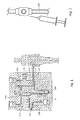
- the reference 100 indicates a hemodialysis machine where a patient's blood is passed through a filter to remove waste products and water.
- the machine 100 known per se, is provided with a disposable tubing set 126 which comprises:
- the substitution tube 116 comprises an insert 30 for the infusion of drugs.
- the tubing set 126 further comprises a drain tube 108 for discharging the waste fluid originating from the filter 106; and a dialysate tube 112 for supplying a dialysate to the filter 106.
- the blood out-tube 102 is suitable to co-operate with a blood pump 104 of said machine 100.
- the drain tube 108 and the substitution tube 116 can be suitable to co-operate with a drain pump 110, and a substitution pump 118, respectively, of the machine 100.
- an assembly 28 for the infusion of drugs comprises the insert 30, placed along the substitution tube 116, and a vial 34.
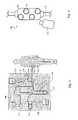
- the insert 30 preferably comprises:
- the vial 34 suitable for containing a therapeutic substance, preferably comprises:
- the access points 32 are intended to receive the fitting of the vial 34, without the need of the intermediate transfer by means of a conventional syringe and the respective needle.
- the single vial 34 can be fitted onto the respective access point 32 through any coupling that allows an airtight fit even in the presence of pressure difference between the inside and the outside of the circuit 26. Such a result can be obtained through a threaded coupling, a bayonet coupling, a snap coupling, an interference coupling or similar. It should be noted how the access points 32 according to the invention do not use the solution of the puncturable cap. Indeed, it has been considered that the use of the syringe and relative needle is disadvantageous overall due to the costs connected to the consumed material, the time required by the relative operations and the risks of the service staff being pricked through their use.
- each of the access points 32 is designed for a single use. Indeed, see for example figures 11 and 17 , they comprise mechanical connection means 36 and hydraulic connection means 38.
- a membrane 40 ensures the sterility of the hydraulic connection means 38, which are those involved in the passage of the therapeutic substance. The membrane 40 must be broken or removed in order to be able to couple the desired vial 34 with the respective access point 32.
- the vial 34 is left fitted onto the access point 32 even when it no longer contains any drugs, thus protecting the access point from any external contamination.
- the insert 30 is disposed of together with the vial 34 fitted onto it and the entire disposable tubing set 126.
- the vial 34 also comprises mechanical connection means 42 and hydraulic connection means 44.
- a membrane 46 ensures the sterility of the hydraulic connection means 44, which are those involved in the passage of the therapeutic substance. The membrane 46 must be broken or removed in order to be able to couple the vial 34 with the respective access point 32.
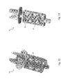
- Figures 9 to 13 show a first embodiment of the insert 30 having an overall parallelepiped shape and in which the access points 32 are arranged on the same face of the parallelepiped and have axes parallel to one another.
- Figures 14 and 15 show a second embodiment of the insert 30 having an overall tube shape and in which the access points 32 are arranged radially around the tube.
- the machine 100 comprises a housing of a suitable shape and size for the insertion of the standard heparin syringe.
- the insert 30 has the shape and size of a standard heparin syringe, so as to be able to be positioned in such a housing instead of the heparin syringe.
- Such a solution is represented in figures 9 and 14 .
- the insert 30 can be arranged downstream of the substitution pump 118. In these configurations, therefore, the substitution fluid which reaches the insert 30 is at a higher pressure than atmospheric pressure. In accordance with some other configurations of the tubing set 126 according to the invention, for example that of figure 8 , the insert 30 can, on the other hand, be arranged upstream of the substitution pump 118. In these configurations, therefore, the substitution fluid which reaches the insert 30 is at a lower pressure than atmospheric pressure.
- substitution tube 116 is advantageously used for the infusion of the therapeutic substances instead of the blood out-tube 102 or blood in-tube 114.
- the insert 30 according to the invention is therefore arranged along substitution tube 116 rather than along the blood tubes 102, 114.
- the vials 34 according to the invention can be made from glass or, advantageously, polymeric material. Concerning this, it should be noted that not all therapeutic substances can be contained in polymeric vials. For some of them it is necessary to provide glass vials.
- the polymeric vials can, for example, be made from polypropylene through blow-moulding. Of course, other polymers and other technologies can, if needed, satisfy specific particular requirements.
- the polymeric vials can advantageously be squeezed, so as to expel the substance contained in it. Should the vial 34 be fitted onto an insert 30 arranged upstream of the substitution pump 118, the depression inside the substitution tube 116 autonomously sucks up the substance contained in the vial 34. The possibility of the substance being dispensed in this way is ensured by the fact that the polymeric vial 34 can collapse as the volume of substance contained inside it reduces.
- the substitution tube 116 is under pressure.
- the substitution tube 116 is under pressure.
- the vials 34 made from glass do not allow these ways of dispensing the contained substances.
- the access point 32 of the insert 30 according to the invention can be configured so as to induce an internal washing of the vial 34 in order to remove its content.
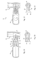
- Figure 16 illustrates a vial 34 according to the invention made from glass.
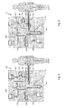
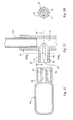
- Figure 17 illustrates, in section, an access point 32 according to the invention.
- Such an access point 32 comprises a movable spike 48.
- the action of bringing the vial 34 up to the access point 32 involves firstly breaking the membrane 40 that protects the hydraulic connection means 38.
- the movable spike 48 makes contact with the membrane 46 of the vial itself, in turn breaking it.
- the movable spike 48 makes contact with the hydraulic connection means 44 of the vial 34 and is pushed by them towards the inside of the insert 30.
- a vial 34 comprising single hydraulic connection means 44.
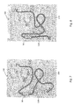
- a different washing system can be obtained with a different vial 34, of the type illustrated in figures 23 to 26 .
- Such a vial comprises double connection means: first mechanical connection means 42' and first hydraulic connection means 44' suitable for being fitted onto an access point 32; and second mechanical connection means 42" and second hydraulic connection means 44" arranged substantially at the opposite ends of the vial 34.
- a flow of substitution fluid enters through the second hydraulic connection means 44" into the vial 34, mixes with the substance contained in it and finally comes out, through the first hydraulic connection means 44' .
- the insert 30 is placed along the substitution tube 116.
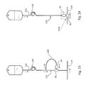
- the substitution tube 116 comprises a secondary branch 120 diverting from the substitution tube 116 and connecting again with it.
- the insert 30 is placed at the connection between the secondary branch 120 and the substitution tube 116.
- the substitution fluid which enters into the vial 34 comes from the secondary branch 120 and flows again into the substitution tube 116.
- the insert 30 is placed at the connection of the substitution tube 116 with the blood in-tube 114.
- the flow that enters into the vial 34 is the whole substitution fluid flow immediately upstream of the convergence with the blood in-tube 114.
- the insert 30 can be placed at the connection of the substitution tube 116 with the blood out-tube 102.
- tubing set 126 allows to perform automated processes for the delivery of any medicament.
- the particular arrangement of the tubing set 126 according to the invention permits to utilize the flow of the substitution fluid for automatically sucking the drug out of any vial, either collapsible or rigid.
- Such solution allows administering of drugs without needing the active presence of the service staff, even if a slow release is needed.
- the insert 30 comprises a plurality of access points 32.
- the plurality of access points 32 allows multiple and simultaneous dispensing of drugs and/or therapeutic substances.
- the invention relates finally to a method for delivering drugs into the extracorporeal blood circuit of a hemodialysis machine.
- the method according to the invention comprises the steps of:
- the step of infusing a drug into said substitution fluid comprises the step of connecting a vial 34 to the insert 30 and, preferably, using the flow of the substitution fluid for automatically sucking the drug out of the vial.
- the present invention overcomes most of the drawbacks pointed out with respect to the prior art.
- the present invention allows to automatically deliver any medicament in an extracorporeal circuit in a lot of different conditions.
- the delivery can be carried out up- or downstream the filter, up- or downstream the substitution pump, from collapsible or rigid vials, and with different delivery rates.
Abstract
The present invention refers to a tubing set (126) suitable for use in co-operation with a machine (100) for carrying out a hemodialysis treatment of a patient's blood. The tubing set comprises: a blood out-tube (102) for supplying the blood from the patient to a filter (106) of said machine; a blood in-tube (114) for supplying the blood from the filter back to the patient; and a substitution tube (116) connected to one of said blood in-tube or blood out-tube suitable for providing a substitution fluid in the patient's blood. According to the invention, the substitution tube comprises an insert (30) for the infusion of drugs. The invention further refers to the insert and to a vial (34) suitable to co-operate with the insert. The invention finally refers to a method for delivering drugs.
Description
- The invention concerns a tubing set comprising an insert for the infusion of drugs in extracorporeal circuits, in particular a tubing set intended to be used with hemodialysis machines. The invention further concerns a vial suitable for being fitted onto the insert.
- In therapeutic treatment that require an extracorporeal circulation it is often necessary to administer different drugs or therapeutic substances to the patient. The presence of the tubing set advantageously makes it possible to avoid the administering of the drug taking place through puncture carried out directly on the patient himself.
- As an example, hereafter we consider hemodialysis treatment, without for this reason limiting the scope of the invention to this specific application.
- Most of the recent hemodialysis machines, are arranged also for carrying out another treatment, called hemofiltration. Hemofiltration is a renal replacement therapy which is used almost exclusively for acute renal failure. During hemofiltration, a patient's blood is passed through a filter where waste products and water are removed. Due to the water removal, a substitution fluid is needed in addition to the blood which is returned to the patient. Hemofiltration is sometimes used in combination with hemodialysis, originating the so called hemodiafiltration treatment.
- In view of the above, recent hemodialysis machines, are provided with a specific circuit intended to deliver the substitution fluid.
- In the following, for ease of description, reference will be made to hemodialysis only, however hemofiltration and hemodiafiltration should also be considered within the scope of the present invention.
- During such treatments it often becomes necessary to administer different drugs or therapeutic substances, like for example iron, heparin, erythropoietin and vitamin D. The infusion of such substances in the extracorporeal circuit is currently carried out through conventional syringes. The substance is drawn from the vial in which it is supplied by the producer and is then injected into a special puncturable cap provided along the tubing set. Thus there is a double transfer of the substance: firstly from the vial to the syringe and then from the syringe to the circuit.
- Such an operation therefore requires the use of disposable materials, such as the syringe and the respective needle, just to transfer the substance from the vial to the tubing set. Moreover, the use of needles always carries the risk of the service staff being pricked.
- Furthermore, during the infusion of some therapeutic substances in the patient's blood, attention must be paid in order to avoid hemolysis.
- Finally, some of the quoted substances need to be administered slowly, over a few minutes. From this it can easily be understood how the administering of various substances to more than one patient represents a considerable workload for the nursing staff responsible for the treatment.
- Two automated processes for delivery of heparin are disclosed in the prior art. A specific pump for acting on the heparin syringe is disclosed in
EP 1 909 866 . According to this first solution, this specific pump can be used only for heparin, while it can not be used for any other medicament. - A different solution is disclosed in
US 5,015,226 wherein the negative pressure induced in the blood conduit by the blood pump is used for sucking the heparin out of the vial. Since the blood pump is located upstream the dialysis filter, this method is only usable with medicaments which can not pass the filter membrane. Furthermore, in such process can be used collapsible vials only, since there is no possibility to effectively suck a medicament out of a rigid vial by way of the negative pressure. - Other tubing sets and the related assemblies for the infusion of substances in the extracorporeal circuit are described in detail in documents
US 5,693,008 ;US 5,983,947 ;US 2009/0101552 andWO 2008/106191 . - The purpose of the present invention is therefore to at least partially solve the drawbacks highlighted in relation to known tubing sets for infusion.
- A task of the present invention is to avoid the double transfer of the substance.
- Another task of the present invention is to make it possible to avoid the use of conventional syringes and the respective needles.
- A task of the present invention is to allow the infusion of therapeutic substances without any risk of hemolysis for the patient's blood.
- Another task of the present invention is to allow automated processes for the delivery of any medicament, e.g. to allow slow administering of the substances that require it without needing the active presence of the service staff to do so.
- A task of the present invention is to allow even simultaneous infusion of a plurality of drugs.
- The purpose and the tasks indicated above are accomplished by a tubing set according to claim 1, by an insert for infusion according to claim 7, by a vial according to claim 8 and by a method according to claim 12.
- The characteristics and the further advantages of the invention shall become clear from the following description of some embodiments, given for indicating and not limiting purposes with reference to the attached drawings, in which:
-
Figure 1 schematically represents an extracorporeal circuit used in a hemodialysis treatment according to the prior art; -
Figure 2 schematically represents the detail, indicated with II infigure 1 , of the puncturable cap for administering substances according to the prior art; -
Figure 3 schematically represents an extracorporeal circuit used in a hemodialysis treatment according to the invention; -
Figure 4 schematically represents the detail, indicated with IV infigure 3 , of the assembly for administering substances according to the invention; -
Figure 5 schematically represents another extracorporeal circuit used in a hemodialysis treatment according to the invention; -
Figure 6 schematically represents a further extracorporeal circuit used in a hemodialysis treatment according to the invention; -
Figure 7 schematically represents an extracorporeal circuit comprising an insert according to the invention in a first configuration; -
Figure 8 schematically represents an extracorporeal circuit comprising an insert according to the invention in a second configuration; -
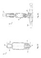
Figure 9 represents a front view of an insert of a tubing set according to the invention applied to a known machine; -
Figure 10 represents a front view partially in section of the insert offigure 9 ; -
Figure 11 represents a side view partially in section of the insert offigure 9 and of a vial suitable for being fitted onto it; -
Figure 12 represents a perspective view of the insert offigure 9 ; -
Figure 13 represents a view similar to that offigure 12 in which part of the outer cover of the insert has been removed; -
Figure 14 represents a front view of another insert of a tubing set according to the invention applied to a known machine; -
Figure 15 represents a front view, partially in section, of the assembly comprising the insert offigure 14 and a vial fitted onto it; -
Figure 16 represents a detailed section view of a vial according to the invention suitable for being fitted onto an insert according to the invention; -
Figure 17 represents a detailed section view of an insert according to the invention suitable for receiving the fitting of the vial offigure 16 ; -
Figure 18 represents a section view along the line XVIII-XVIII offigure 17 ; -
Figure 19 represents a section view of the vial offigure 16 brought up to the insert offigure 17 ; -
Figure 20 represents a section view along the line XX-XX offigure 17 ; -
Figure 21 represents a section view of the assembly according to the invention comprising the insert offigure 17 and the vial offigure 16 fitted onto it; -
Figure 22 represents a section view similar to that offigure 20 in a different configuration; -
Figure 23 schematically represents a portion of a tubing set according to the invention in an extracorporeal circuit; -
Figure 24 schematically represents a portion of another tubing set according to the invention in an extracorporeal circuit; -
Figure 25 represents a detailed section view of another vial according to the invention suitable for being fitted onto an insert in a tubing set according to the invention; -
Figure 26 represents the detail, indicated with XXVI infigure 24 , i.e. represents the vial offigure 25 coupled with an insert in the tubing set according to the invention. - With specific reference to the enclosed figures, the
reference 100 indicates a hemodialysis machine where a patient's blood is passed through a filter to remove waste products and water. Themachine 100, known per se, is provided with adisposable tubing set 126 which comprises: - a blood out-
tube 102 for supplying the blood from the patient to afilter 106 of themachine 100; - a blood in-
tube 114 for supplying the blood from thefilter 106 back to the patient; and - a
substitution tube 116 connected to one of said blood in-tube 114 or blood out-tube 102 suitable for providing a substitution fluid in the patient's blood. - In the tubing set 126 according to the invention, the
substitution tube 116 comprises aninsert 30 for the infusion of drugs. - According to some embodiment of the invention, the tubing set 126 further comprises a
drain tube 108 for discharging the waste fluid originating from thefilter 106; and adialysate tube 112 for supplying a dialysate to thefilter 106. According to some embodiment of the invention, the blood out-tube 102 is suitable to co-operate with ablood pump 104 of saidmachine 100. Similarly, thedrain tube 108 and thesubstitution tube 116 can be suitable to co-operate with adrain pump 110, and asubstitution pump 118, respectively, of themachine 100. According to an embodiment of the invention, anassembly 28 for the infusion of drugs comprises theinsert 30, placed along thesubstitution tube 116, and avial 34. Theinsert 30 preferably comprises: - a
main duct 31 suitable for ensuring the fluid continuity of thesubstitution tube 116; - at least one
access point 32 comprising mechanical connection means 36 and hydraulic connection means 38, suitable for being connected to thevial 34 containing a therapeutic substance; - a
membrane 40 suitable for ensuring the sterility of the hydraulic connection means 38 and intended to be broken or removed in order to be able to couple thevial 34. - The
vial 34, suitable for containing a therapeutic substance, preferably comprises: - mechanical connection means 42 and hydraulic connection means 44, suitable for being fitted onto the
access point 32 of theinsert 30; - a
membrane 46 suitable for ensuring the sterility of the hydraulic connection means 44 and intended to be broken or removed in order to be able to fit thevial 34 onto therespective access point 32. - The access points 32 are intended to receive the fitting of the
vial 34, without the need of the intermediate transfer by means of a conventional syringe and the respective needle. - The
single vial 34 can be fitted onto therespective access point 32 through any coupling that allows an airtight fit even in the presence of pressure difference between the inside and the outside of thecircuit 26. Such a result can be obtained through a threaded coupling, a bayonet coupling, a snap coupling, an interference coupling or similar. It should be noted how the access points 32 according to the invention do not use the solution of the puncturable cap. Indeed, it has been considered that the use of the syringe and relative needle is disadvantageous overall due to the costs connected to the consumed material, the time required by the relative operations and the risks of the service staff being pricked through their use. - What has been stated above does not of course rule out the possibility of an
insert 30 according to the invention comprising, alongside the access points 32 intended for thevial 34, also one or more known puncturable caps. Such a provision ensures that theinsert 30 according to the invention is also compatible with the prior art and thus allows possible stocks not specifically intended for use in combination with theinsert 30 to be used up. - In accordance with some embodiments, each of the access points 32 is designed for a single use. Indeed, see for example
figures 11 and17 , they comprise mechanical connection means 36 and hydraulic connection means 38. Amembrane 40 ensures the sterility of the hydraulic connection means 38, which are those involved in the passage of the therapeutic substance. Themembrane 40 must be broken or removed in order to be able to couple the desiredvial 34 with therespective access point 32. During the therapeutic treatment thevial 34 is left fitted onto theaccess point 32 even when it no longer contains any drugs, thus protecting the access point from any external contamination. At the end of the treatment theinsert 30 is disposed of together with thevial 34 fitted onto it and the entire disposable tubing set 126. - In accordance with some embodiments, the
vial 34 also comprises mechanical connection means 42 and hydraulic connection means 44. Amembrane 46 ensures the sterility of the hydraulic connection means 44, which are those involved in the passage of the therapeutic substance. Themembrane 46 must be broken or removed in order to be able to couple thevial 34 with therespective access point 32. -
Figures 9 to 13 show a first embodiment of theinsert 30 having an overall parallelepiped shape and in which the access points 32 are arranged on the same face of the parallelepiped and have axes parallel to one another.Figures 14 and 15 show a second embodiment of theinsert 30 having an overall tube shape and in which the access points 32 are arranged radially around the tube. - In a known way, the
machine 100 comprises a housing of a suitable shape and size for the insertion of the standard heparin syringe. In accordance with an embodiment, theinsert 30 has the shape and size of a standard heparin syringe, so as to be able to be positioned in such a housing instead of the heparin syringe. Such a solution is represented infigures 9 and14 . - In accordance with some configurations of the tubing set 126 according to the invention, for example that of
figure 7 , theinsert 30 can be arranged downstream of thesubstitution pump 118. In these configurations, therefore, the substitution fluid which reaches theinsert 30 is at a higher pressure than atmospheric pressure. In accordance with some other configurations of the tubing set 126 according to the invention, for example that offigure 8 , theinsert 30 can, on the other hand, be arranged upstream of thesubstitution pump 118. In these configurations, therefore, the substitution fluid which reaches theinsert 30 is at a lower pressure than atmospheric pressure. - From what has been stated above, the person skilled in the art will understand that the dispensing of the substance contained inside the
vial 34 will be carried out in different ways according to the case. Such ways shall be outlined later, with reference also to the different possible configurations for thevials 34 themselves. Thesubstitution tube 116 is advantageously used for the infusion of the therapeutic substances instead of the blood out-tube 102 or blood in-tube 114. Theinsert 30 according to the invention is therefore arranged alongsubstitution tube 116 rather than along theblood tubes - The
vials 34 according to the invention can be made from glass or, advantageously, polymeric material. Concerning this, it should be noted that not all therapeutic substances can be contained in polymeric vials. For some of them it is necessary to provide glass vials. - The polymeric vials can, for example, be made from polypropylene through blow-moulding. Of course, other polymers and other technologies can, if needed, satisfy specific particular requirements. The polymeric vials can advantageously be squeezed, so as to expel the substance contained in it. Should the
vial 34 be fitted onto aninsert 30 arranged upstream of thesubstitution pump 118, the depression inside thesubstitution tube 116 autonomously sucks up the substance contained in thevial 34. The possibility of the substance being dispensed in this way is ensured by the fact that thepolymeric vial 34 can collapse as the volume of substance contained inside it reduces. - If, on the other hand, the
insert 30 is arranged downstream of thesubstitution pump 118, thesubstitution tube 116 is under pressure. In this case, to dispense the substance contained in thevial 34, it is necessary to apply a pressure at least slightly greater than that present in thesubstitution tube 116. In this case, and should the substance be able to be dispensed in a single solution instead of a little at a time, it is for example possible to manually squeeze thevial 34. - The
vials 34 made from glass, of course, do not allow these ways of dispensing the contained substances. In this case, theaccess point 32 of theinsert 30 according to the invention can be configured so as to induce an internal washing of thevial 34 in order to remove its content. - One particular embodiment of the
access point 32 that allows such washing is described hereafter with reference tofigures 16 to 22 . -
Figure 16 illustrates avial 34 according to the invention made from glass.Figure 17 illustrates, in section, anaccess point 32 according to the invention. Such anaccess point 32 comprises amovable spike 48. As can be seen infigure 19 , the action of bringing thevial 34 up to theaccess point 32 involves firstly breaking themembrane 40 that protects the hydraulic connection means 38. Continuing in the action of fitting thevial 34, themovable spike 48 makes contact with themembrane 46 of the vial itself, in turn breaking it. Continuing further in the fitting, themovable spike 48 makes contact with the hydraulic connection means 44 of thevial 34 and is pushed by them towards the inside of theinsert 30. The final effect of this movement of themovable spike 48 can be seen by comparingfigures 19 and 21 and, respectively, 20 and 22. In the final configuration shown infigures 21 and 22 , the root of themovable spike 48 at least partially obstructs themain duct 31 of theinsert 30. The flow prevented in themain duct 31 is thus deviated inside thevial 34. The main flow enters into thevial 34, mixes with the substance originally contained in it and finally comes out, pushed by the new fluid deviated by the root of themovable spike 48. The aforementioned washing is thus obtained, schematically indicated by the dotted arrows infigure 21 . - The washing described above is obtained for a
vial 34 according to the invention, comprising single hydraulic connection means 44. A different washing system can be obtained with adifferent vial 34, of the type illustrated infigures 23 to 26 . Such a vial comprises double connection means: first mechanical connection means 42' and first hydraulic connection means 44' suitable for being fitted onto anaccess point 32; and second mechanical connection means 42" and second hydraulic connection means 44" arranged substantially at the opposite ends of thevial 34. In this case a flow of substitution fluid enters through the second hydraulic connection means 44" into thevial 34, mixes with the substance contained in it and finally comes out, through the first hydraulic connection means 44' . - In accordance with the embodiment schematically shown in
figure 23 , theinsert 30 is placed along thesubstitution tube 116. In such embodiment, thesubstitution tube 116 comprises asecondary branch 120 diverting from thesubstitution tube 116 and connecting again with it. Theinsert 30 is placed at the connection between thesecondary branch 120 and thesubstitution tube 116. The substitution fluid which enters into thevial 34 comes from thesecondary branch 120 and flows again into thesubstitution tube 116. - In accordance with the embodiment schematically shown in
figure 24 , theinsert 30 is placed at the connection of thesubstitution tube 116 with the blood in-tube 114. In such embodiment, the flow that enters into thevial 34 is the whole substitution fluid flow immediately upstream of the convergence with the blood in-tube 114. According to a different embodiment of the tubing set 126, theinsert 30 can be placed at the connection of thesubstitution tube 116 with the blood out-tube 102. - The same concepts for dispensing the content of the
vial 34 through washing can be exploited for polymeric vials when fitted downstream of thesubstitution pump 118. - In view of the above description, the skilled person can appreciate that the tubing set 126 according to the invention allows to perform automated processes for the delivery of any medicament. In fact, the particular arrangement of the tubing set 126 according to the invention permits to utilize the flow of the substitution fluid for automatically sucking the drug out of any vial, either collapsible or rigid. Such solution allows administering of drugs without needing the active presence of the service staff, even if a slow release is needed.
- In accordance with some embodiments, see for example
figures 3 to 15 , theinsert 30 comprises a plurality of access points 32. The plurality ofaccess points 32 allows multiple and simultaneous dispensing of drugs and/or therapeutic substances. - The invention relates finally to a method for delivering drugs into the extracorporeal blood circuit of a hemodialysis machine. The method according to the invention comprises the steps of:
- connecting a blood out-
tube 102 to the patient for supplying the blood to afilter 106 of thehemodialysis machine 100; - connecting a blood in-
tube 114 to the patient for supplying the blood from thefilter 106 back to the patient; and - connecting a
substitution tube 116 to one of said blood in-tube 114 or blood out-tube 102 for providing a substitution fluid to replace the waste water removed from the blood by thefilter 106 during the hemodialysis treatment, saidsubstitution tube 116 comprising aninsert 30 for the infusion of drugs; and - infusing a drug by means of said
insert 30 into said substitution fluid. - According to an embodiment of the method, the step of infusing a drug into said substitution fluid comprises the step of connecting a
vial 34 to theinsert 30 and, preferably, using the flow of the substitution fluid for automatically sucking the drug out of the vial. - In view of the above description, the skilled person will easily appreciate that the present invention overcomes most of the drawbacks pointed out with respect to the prior art. In fact, the present invention allows to automatically deliver any medicament in an extracorporeal circuit in a lot of different conditions. Specifically, the delivery can be carried out up- or downstream the filter, up- or downstream the substitution pump, from collapsible or rigid vials, and with different delivery rates.
- The person skilled in the art can bring modifications and/or replacements of described element with equivalent elements to the embodiments of the tubing set 126, of the
insert 30 and of thevial 34 according to the invention described above, in order to satisfy specific requirements, without for this reason departing from the scope of the attached claims.
Claims (13)
- Tubing set (126) suitable for use in co-operation with a machine (100) for carrying out a hemodialysis treatment of a patient's blood, comprising:- a blood out-tube (102) for supplying the blood from the patient to a filter (106) of said machine (100);- a blood in-tube (114) for supplying the blood from the filter (106) back to the patient; and- a substitution tube (116) connected to one of said blood in-tube (114) or blood out-tube (102) suitable for providing a substitution fluid in the patient's blood,wherein said substitution tube (116) comprises an insert (30) for the infusion of drugs.
- Tubing set (126) according to claim 1 further comprising:- a drain tube (108) for discharging the waste fluid originating from the filter (106); and- a dialysate tube (112) for supplying the dialysate to the filter (106).
- Tubing set (126) according to claim 1 or 2, wherein said blood out-tube (102), said drain tube (108) and said substitution tube (116) are suitable to co-operate, respectively, with a blood pump (104), a drain pump (110), and a substitution pump (118) of said machine (100).
- Tubing set (126) according to any preceding claim, wherein said insert (30) for the infusion of drugs is placed at the connection between said substitution tube (116) and said blood in-tube (114) or blood out-tube (102).
- Tubing set (126) according to any preceding claim, wherein said substitution tube (116) comprises a secondary branch (120) diverting from said substitution tube (116) and connecting again with it.
- Tubing set (126) according to the preceding claim, wherein said insert (30) for the infusion of drugs is placed at the connection between said secondary branch (120) and said substitution tube (116).
- Insert (30) comprised in a tubing set (126) according to any preceding claim, wherein said insert (30) comprises:- a main duct (31) suitable for ensuring the fluid continuity of the substitution tube (116);- at least one access point (32) comprising mechanical connection means (36) and hydraulic connection means (38) suitable for being connected to a vial (34) containing a therapeutic substance;- a membrane (40) suitable for ensuring the sterility of the hydraulic connection means (38) and intended to be broken or removed in order to be able to couple the vial (34).
- Vial (34) suitable for containing a therapeutic substance, comprising:- mechanical connection means (42) and hydraulic connection means (44) suitable for being fitted onto an access point (32) of an insert (30) according to claim 7;- a membrane (46) suitable for ensuring the sterility of the hydraulic connection means (44) and intended to be broken or removed in order to be able to fit the vial (34) onto the respective access point (32).
- Vial (34) according to the preceding claim, comprising:- first mechanical connection means (42') and first hydraulic connection means (44') suitable for being fitted onto an access point (32) of an insert (30); and- second mechanical connection means (42") and second hydraulic connection means (44") suitable for being fitted onto said substitution tube (116) and/or onto said secondary branch (120).
- Insert (30) according to claim 7, wherein said access point (32) comprises a movable spike (48) which, when a vial (34) according to claim 8 is fitted onto said access point (32), is suitable for:- breaking the membrane (46) of the vial (34), and- at least partially obstructing the main duct (31) of the insert (30) so as to deviate the flow inside the vial (34).
- Tubing set (126) according to any preceding claim, wherein said insert (30) has the shape and size of a standard heparin syringe, so as to be positioned in a housing of the machine (100) of a suitable shape and size for the insertion of the standard heparin syringe.
- Method for delivering drugs into an extracorporeal blood circuit of a hemodialysis machine, comprising the steps of:- connecting a blood out-tube (102) to the patient for supplying the blood to a filter (106) of the hemodialysis machine (100);- connecting a blood in-tube (114) to the patient for supplying the blood from the filter (106) back to the patient; and- connecting a substitution tube (116) to one of said blood in-tube (114) or blood out-tube (102) suitable for providing a substitution fluid in the patient's blood, said substitution tube (116) comprising an insert (30) for the infusion of drugs; and- infusing a drug by means of said insert (30) into said substitution fluid.
- Method according to the preceding claim, wherein the step of infusing a drug into said substitution fluid comprises the step of connecting a vial (34) to the insert (30) and using the flow of the substitution fluid for automatically sucking the drug out of the vial (34).
Priority Applications (12)
| Application Number | Priority Date | Filing Date | Title |
|---|---|---|---|
| EP20090171888 EP2305204A1 (en) | 2009-09-30 | 2009-09-30 | Tubing set having an insert for the infusion of drugs |
| CA2775979A CA2775979C (en) | 2009-09-30 | 2010-09-30 | Tubing set having an insert for the infusion of drugs |
| PCT/EP2010/064559 WO2011039306A1 (en) | 2009-09-30 | 2010-09-30 | Tubing set having an insert for the infusion of drugs |
| KR1020127011125A KR101663688B1 (en) | 2009-09-30 | 2010-09-30 | Tubing set having an insert for the infusion of drugs |
| BR112012008369-4A BR112012008369B1 (en) | 2009-09-30 | 2010-09-30 | TUBE SET WITH AN INSERTION PIECE FOR DRUG INFUSION |
| JP2012531427A JP2013506471A (en) | 2009-09-30 | 2010-09-30 | Piping set with inserts for drug injection |
| US13/498,681 US9623227B2 (en) | 2009-09-30 | 2010-09-30 | Tubing set having an insert for the infusion of drugs |
| ES10759672.8T ES2586066T3 (en) | 2009-09-30 | 2010-09-30 | Probe set equipped with an insert for drug infusion |
| AU2010302694A AU2010302694B2 (en) | 2009-09-30 | 2010-09-30 | Tubing set having an insert for the infusion of drugs |
| EP10759672.8A EP2482785B1 (en) | 2009-09-30 | 2010-09-30 | Tubing set having an insert for the infusion of drugs |
| CN201080043501.8A CN102548521B (en) | 2009-09-30 | 2010-09-30 | There is the conduit assembly of the insert for infusion of drug |
| JP2015030624A JP6076390B2 (en) | 2009-09-30 | 2015-02-19 | Piping set with inserts for drug injection |
Applications Claiming Priority (1)
| Application Number | Priority Date | Filing Date | Title |
|---|---|---|---|
| EP20090171888 EP2305204A1 (en) | 2009-09-30 | 2009-09-30 | Tubing set having an insert for the infusion of drugs |
Publications (1)
| Publication Number | Publication Date |
|---|---|
| EP2305204A1 true EP2305204A1 (en) | 2011-04-06 |
Family
ID=41571525
Family Applications (2)
| Application Number | Title | Priority Date | Filing Date |
|---|---|---|---|
| EP20090171888 Withdrawn EP2305204A1 (en) | 2009-09-30 | 2009-09-30 | Tubing set having an insert for the infusion of drugs |
| EP10759672.8A Active EP2482785B1 (en) | 2009-09-30 | 2010-09-30 | Tubing set having an insert for the infusion of drugs |
Family Applications After (1)
| Application Number | Title | Priority Date | Filing Date |
|---|---|---|---|
| EP10759672.8A Active EP2482785B1 (en) | 2009-09-30 | 2010-09-30 | Tubing set having an insert for the infusion of drugs |
Country Status (10)
| Country | Link |
|---|---|
| US (1) | US9623227B2 (en) |
| EP (2) | EP2305204A1 (en) |
| JP (2) | JP2013506471A (en) |
| KR (1) | KR101663688B1 (en) |
| CN (1) | CN102548521B (en) |
| AU (1) | AU2010302694B2 (en) |
| BR (1) | BR112012008369B1 (en) |
| CA (1) | CA2775979C (en) |
| ES (1) | ES2586066T3 (en) |
| WO (1) | WO2011039306A1 (en) |
Cited By (1)
| Publication number | Priority date | Publication date | Assignee | Title |
|---|---|---|---|---|
| CN104473714A (en) * | 2014-12-08 | 2015-04-01 | 刘思伯 | Extravascular cooling and mild hypothermia treatment control system and application thereof |
Families Citing this family (6)
| Publication number | Priority date | Publication date | Assignee | Title |
|---|---|---|---|---|
| EP2462913A1 (en) * | 2010-12-10 | 2012-06-13 | Fresenius Medical Care Deutschland GmbH | Insert and vial for the infusion of liquids |
| GB201202093D0 (en) * | 2012-02-07 | 2012-03-21 | Renishaw Ireland Ltd | Drug storage apparatus |
| GB201202091D0 (en) | 2012-02-07 | 2012-03-21 | Renishaw Ireland Ltd | Drug delivery apparatus |
| EP3421061A1 (en) * | 2017-06-28 | 2019-01-02 | Fresenius Medical Care Deutschland GmbH | Another insert piece for a blood tubing set to promote mixing an infusion solution with a further fluid |
| US11944588B2 (en) | 2018-05-11 | 2024-04-02 | Bristol-Myers Squibb Company | Devices and systems for delivery of combination therapies |
| JP6783897B1 (en) * | 2019-05-09 | 2020-11-11 | 日機装株式会社 | Blood purification device |
Citations (9)
| Publication number | Priority date | Publication date | Assignee | Title |
|---|---|---|---|---|
| WO1990012606A2 (en) * | 1989-04-10 | 1990-11-01 | Baxter International Inc. | iRE-SLIT INJECTION SITE AND TAPERED CANNULA |
| US5015226A (en) | 1988-11-03 | 1991-05-14 | Fresenius Ag | Apparatus for infusion of medicaments |
| US5693008A (en) | 1995-06-07 | 1997-12-02 | Cobe Laboratories, Inc. | Dialysis blood tubing set |
| US5983947A (en) | 1997-03-03 | 1999-11-16 | Medisystems Technology Corporation | Docking ports for medical fluid sets |
| WO1999061093A1 (en) * | 1998-05-29 | 1999-12-02 | Lynn Lawrence A | Luer receiver and method for fluid transfer |
| EP1909866A1 (en) | 2005-07-29 | 2008-04-16 | Gambro Lundia AB | A machine for extracorporeal blood treatment |
| WO2008106191A2 (en) | 2007-02-27 | 2008-09-04 | Deka Products Limited Partnership | Hemodialysis systems and methods |
| US20090101552A1 (en) | 2007-09-25 | 2009-04-23 | Fulkerson Barry N | Manifolds for Use in Conducting Dialysis |
| US20090107335A1 (en) * | 2007-02-27 | 2009-04-30 | Deka Products Limited Partnership | Air trap for a medical infusion device |
Family Cites Families (35)
| Publication number | Priority date | Publication date | Assignee | Title |
|---|---|---|---|---|
| US9010A (en) * | 1852-06-08 | Grease-cock | ||
| JPS60261505A (en) * | 1984-06-07 | 1985-12-24 | Kagaku Gijutsucho Hoshasen Igaku Sogo Kenkyusho | Filtration device |
| JPS63135676A (en) * | 1986-11-28 | 1988-06-08 | Kiyoshi Takahashi | Fluid distributor |
| JPH0369839A (en) * | 1989-08-05 | 1991-03-26 | Nissan Motor Co Ltd | Structure for installing bracket of power plant |
| CN2059839U (en) | 1989-10-30 | 1990-08-01 | 天津市肝胆病研究所 | Portable blood purifier |
| US5098405A (en) * | 1991-01-31 | 1992-03-24 | Becton, Dickinson And Company | Apparatus and method for a side port cathether adapter with a one piece integral combination valve |
| DE4230513C1 (en) * | 1992-09-11 | 1994-03-31 | Fresenius Ag | Device for removing aluminum ions from blood and solution for use in the device |
| US5405333A (en) * | 1992-12-28 | 1995-04-11 | Richmond; Frank M. | Liquid medicament bag with needleless connector fitting using boat assembly |
| JP2849540B2 (en) * | 1993-12-28 | 1999-01-20 | 川澄化学工業株式会社 | Body fluid treatment circuit |
| FR2724321A1 (en) * | 1994-09-14 | 1996-03-15 | Hospal Ind | DEVICE FOR MEASURING THE PRESSURE OF A LIQUID AND METHOD FOR ADJUSTING SUCH A DEVICE |
| NZ286445A (en) * | 1995-05-16 | 1997-12-19 | Ivac Corp | Needleless luer connector: deformable piston occludes bore |
| US5618268A (en) * | 1995-06-06 | 1997-04-08 | B. Braun Medical Inc. | Medical infusion devices and medicine delivery systems employing the same |
| US5810768A (en) * | 1995-06-07 | 1998-09-22 | Icu Medical, Inc. | Medical connector |
| US5928177A (en) * | 1995-09-15 | 1999-07-27 | Cobe Laboratories, Inc. | Technique for loading a pump header within a peristaltic pump of a dialysis machine |
| JP3069839B2 (en) * | 1996-09-18 | 2000-07-24 | アロン化成株式会社 | Garbage container |
| US6387069B1 (en) * | 1996-09-23 | 2002-05-14 | Dsu Medical Corporation | Blood set priming method and apparatus |
| JPH11227845A (en) * | 1998-02-19 | 1999-08-24 | Material Eng Tech Lab Inc | Container having mixture-pouring port |
| US7193521B2 (en) * | 1998-10-29 | 2007-03-20 | Medtronic Minimed, Inc. | Method and apparatus for detecting errors, fluid pressure, and occlusions in an ambulatory infusion pump |
| JP3069839U (en) * | 1999-12-21 | 2000-07-04 | 川澄化学工業株式会社 | Extracorporeal circulation circuit |
| JP2001190689A (en) * | 2000-01-14 | 2001-07-17 | Daiichi Radioisotope Labs Ltd | Flow passage changeover valve for dosing liquid medicine, liquid medicine encapsulating body, and cartridge body for dosing liquid medicine |
| JP2002248166A (en) * | 2001-02-22 | 2002-09-03 | Nikkiso Co Ltd | Liquid medicine pouring device |
| US6527758B2 (en) * | 2001-06-11 | 2003-03-04 | Kam Ko | Vial docking station for sliding reconstitution with diluent container |
| US8562583B2 (en) * | 2002-03-26 | 2013-10-22 | Carmel Pharma Ab | Method and assembly for fluid transfer and drug containment in an infusion system |
| EP1560622B1 (en) * | 2002-07-09 | 2008-03-05 | Carmel Pharma AB | A device for injecting medical substances |
| CN2654131Y (en) | 2003-03-03 | 2004-11-10 | 陈振业 | Disposable residual liquid proof pressurized blood/liquid transfusion apparatus |
| US20060089604A1 (en) * | 2004-10-26 | 2006-04-27 | Intrasafe Medical, Llc | Infusion device for administering fluids to a patient |
| EP1813188B1 (en) * | 2006-01-30 | 2011-03-30 | Pulsion Medical Systems AG | System for providing a dilution measuring point |
| CN201006056Y (en) | 2006-12-29 | 2008-01-16 | 上海达华医疗器械有限公司 | Disposable gathering, separating, filtering and back-transfusion blood pipe material system |
| CN101678164B (en) * | 2007-05-04 | 2013-04-03 | 弗雷泽纽斯医疗保健德国有限公司 | Method and device for monitoring a blood treatment unit of an extra-corporeal blood treatment device |
| FR2920314B1 (en) * | 2007-09-05 | 2010-07-30 | Gambro Lundia Ab | EXTRACORPOREAL BLOOD TREATMENT CIRCUIT AND LINE HAVING INFUSION SITE FOR THE OPTIMIZED MIXING OF FLUIDS |
| US8114276B2 (en) * | 2007-10-24 | 2012-02-14 | Baxter International Inc. | Personal hemodialysis system |
| CN201171832Y (en) | 2008-04-03 | 2008-12-31 | 赵蔚菁 | Disposable blood virus inactivation filter |
| CA2670556C (en) * | 2008-06-30 | 2013-02-19 | Tyco Healthcare Group Lp | Discriminating oral tip adaptor |
| US8790330B2 (en) * | 2008-12-15 | 2014-07-29 | Carmel Pharma Ab | Connection arrangement and method for connecting a medical device to the improved connection arrangement |
| US20160008569A1 (en) * | 2014-07-08 | 2016-01-14 | Becton, Dickinson And Company | Antimicrobial actuator for opening the side port of a ported catheter |
-
2009
- 2009-09-30 EP EP20090171888 patent/EP2305204A1/en not_active Withdrawn
-
2010
- 2010-09-30 CA CA2775979A patent/CA2775979C/en not_active Expired - Fee Related
- 2010-09-30 KR KR1020127011125A patent/KR101663688B1/en active IP Right Grant
- 2010-09-30 JP JP2012531427A patent/JP2013506471A/en active Pending
- 2010-09-30 US US13/498,681 patent/US9623227B2/en active Active
- 2010-09-30 BR BR112012008369-4A patent/BR112012008369B1/en not_active IP Right Cessation
- 2010-09-30 ES ES10759672.8T patent/ES2586066T3/en active Active
- 2010-09-30 EP EP10759672.8A patent/EP2482785B1/en active Active
- 2010-09-30 AU AU2010302694A patent/AU2010302694B2/en not_active Ceased
- 2010-09-30 WO PCT/EP2010/064559 patent/WO2011039306A1/en active Application Filing
- 2010-09-30 CN CN201080043501.8A patent/CN102548521B/en active Active
-
2015
- 2015-02-19 JP JP2015030624A patent/JP6076390B2/en not_active Expired - Fee Related
Patent Citations (9)
| Publication number | Priority date | Publication date | Assignee | Title |
|---|---|---|---|---|
| US5015226A (en) | 1988-11-03 | 1991-05-14 | Fresenius Ag | Apparatus for infusion of medicaments |
| WO1990012606A2 (en) * | 1989-04-10 | 1990-11-01 | Baxter International Inc. | iRE-SLIT INJECTION SITE AND TAPERED CANNULA |
| US5693008A (en) | 1995-06-07 | 1997-12-02 | Cobe Laboratories, Inc. | Dialysis blood tubing set |
| US5983947A (en) | 1997-03-03 | 1999-11-16 | Medisystems Technology Corporation | Docking ports for medical fluid sets |
| WO1999061093A1 (en) * | 1998-05-29 | 1999-12-02 | Lynn Lawrence A | Luer receiver and method for fluid transfer |
| EP1909866A1 (en) | 2005-07-29 | 2008-04-16 | Gambro Lundia AB | A machine for extracorporeal blood treatment |
| WO2008106191A2 (en) | 2007-02-27 | 2008-09-04 | Deka Products Limited Partnership | Hemodialysis systems and methods |
| US20090107335A1 (en) * | 2007-02-27 | 2009-04-30 | Deka Products Limited Partnership | Air trap for a medical infusion device |
| US20090101552A1 (en) | 2007-09-25 | 2009-04-23 | Fulkerson Barry N | Manifolds for Use in Conducting Dialysis |
Cited By (1)
| Publication number | Priority date | Publication date | Assignee | Title |
|---|---|---|---|---|
| CN104473714A (en) * | 2014-12-08 | 2015-04-01 | 刘思伯 | Extravascular cooling and mild hypothermia treatment control system and application thereof |
Also Published As
| Publication number | Publication date |
|---|---|
| US9623227B2 (en) | 2017-04-18 |
| AU2010302694A1 (en) | 2012-04-19 |
| BR112012008369B1 (en) | 2020-03-17 |
| JP2015091545A (en) | 2015-05-14 |
| JP2013506471A (en) | 2013-02-28 |
| BR112012008369A2 (en) | 2016-03-22 |
| WO2011039306A1 (en) | 2011-04-07 |
| CA2775979C (en) | 2018-05-01 |
| CN102548521B (en) | 2016-06-01 |
| KR101663688B1 (en) | 2016-10-07 |
| CN102548521A (en) | 2012-07-04 |
| ES2586066T3 (en) | 2016-10-11 |
| KR20120087144A (en) | 2012-08-06 |
| JP6076390B2 (en) | 2017-02-08 |
| EP2482785A1 (en) | 2012-08-08 |
| EP2482785B1 (en) | 2016-05-04 |
| CA2775979A1 (en) | 2011-04-07 |
| AU2010302694B2 (en) | 2015-07-16 |
| US20120184939A1 (en) | 2012-07-19 |
Similar Documents
| Publication | Publication Date | Title |
|---|---|---|
| EP2482785B1 (en) | Tubing set having an insert for the infusion of drugs | |
| KR101857491B1 (en) | Tubing set having an improved gate for the connection of vials | |
| EP3081247B1 (en) | Tubing set having a gate for the connection of vials | |
| JP5690284B2 (en) | Dialysis machine, manifold and method for dialysis machine | |
| EP1161960B1 (en) | Single-use preassembled medical device for administering at least two drugs in preset proportions to patients | |
| EP2745859A1 (en) | Disposable cassette with luer locks and method for packaging | |
| ITMO20100306A1 (en) | CONTAINER FOR MEDICAL SUBSTANCES |
Legal Events
| Date | Code | Title | Description |
|---|---|---|---|
| PUAI | Public reference made under article 153(3) epc to a published international application that has entered the european phase |
Free format text: ORIGINAL CODE: 0009012 |
|
| AK | Designated contracting states |
Kind code of ref document: A1 Designated state(s): AT BE BG CH CY CZ DE DK EE ES FI FR GB GR HR HU IE IS IT LI LT LU LV MC MK MT NL NO PL PT RO SE SI SK SM TR |
|
| AX | Request for extension of the european patent |
Extension state: AL BA RS |
|
| STAA | Information on the status of an ep patent application or granted ep patent |
Free format text: STATUS: THE APPLICATION IS DEEMED TO BE WITHDRAWN |
|
| 18D | Application deemed to be withdrawn |
Effective date: 20111007 |